EP4095420B1 - Flow modulator for a fluid - Google Patents
Flow modulator for a fluid Download PDFInfo
- Publication number
- EP4095420B1 EP4095420B1 EP21176651.4A EP21176651A EP4095420B1 EP 4095420 B1 EP4095420 B1 EP 4095420B1 EP 21176651 A EP21176651 A EP 21176651A EP 4095420 B1 EP4095420 B1 EP 4095420B1
- Authority
- EP
- European Patent Office
- Prior art keywords
- valve body
- toothing
- modulator
- flow
- rotation
- Prior art date
- Legal status (The legal status is an assumption and is not a legal conclusion. Google has not performed a legal analysis and makes no representation as to the accuracy of the status listed.)
- Active
Links
Images


Classifications
-
- F—MECHANICAL ENGINEERING; LIGHTING; HEATING; WEAPONS; BLASTING
- F16—ENGINEERING ELEMENTS AND UNITS; GENERAL MEASURES FOR PRODUCING AND MAINTAINING EFFECTIVE FUNCTIONING OF MACHINES OR INSTALLATIONS; THERMAL INSULATION IN GENERAL
- F16K—VALVES; TAPS; COCKS; ACTUATING-FLOATS; DEVICES FOR VENTING OR AERATING
- F16K3/00—Gate valves or sliding valves, i.e. cut-off apparatus with closing members having a sliding movement along the seat for opening and closing
- F16K3/02—Gate valves or sliding valves, i.e. cut-off apparatus with closing members having a sliding movement along the seat for opening and closing with flat sealing faces; Packings therefor
- F16K3/04—Gate valves or sliding valves, i.e. cut-off apparatus with closing members having a sliding movement along the seat for opening and closing with flat sealing faces; Packings therefor with pivoted closure members
- F16K3/06—Gate valves or sliding valves, i.e. cut-off apparatus with closing members having a sliding movement along the seat for opening and closing with flat sealing faces; Packings therefor with pivoted closure members in the form of closure plates arranged between supply and discharge passages
- F16K3/08—Gate valves or sliding valves, i.e. cut-off apparatus with closing members having a sliding movement along the seat for opening and closing with flat sealing faces; Packings therefor with pivoted closure members in the form of closure plates arranged between supply and discharge passages with circular plates rotatable around their centres
-
- F—MECHANICAL ENGINEERING; LIGHTING; HEATING; WEAPONS; BLASTING
- F16—ENGINEERING ELEMENTS AND UNITS; GENERAL MEASURES FOR PRODUCING AND MAINTAINING EFFECTIVE FUNCTIONING OF MACHINES OR INSTALLATIONS; THERMAL INSULATION IN GENERAL
- F16K—VALVES; TAPS; COCKS; ACTUATING-FLOATS; DEVICES FOR VENTING OR AERATING
- F16K31/00—Actuating devices; Operating means; Releasing devices
- F16K31/44—Mechanical actuating means
- F16K31/53—Mechanical actuating means with toothed gearing
- F16K31/535—Mechanical actuating means with toothed gearing for rotating valves
-
- F—MECHANICAL ENGINEERING; LIGHTING; HEATING; WEAPONS; BLASTING
- F23—COMBUSTION APPARATUS; COMBUSTION PROCESSES
- F23N—REGULATING OR CONTROLLING COMBUSTION
- F23N1/00—Regulating fuel supply
- F23N1/005—Regulating fuel supply using electrical or electromechanical means
-
- F—MECHANICAL ENGINEERING; LIGHTING; HEATING; WEAPONS; BLASTING
- F16—ENGINEERING ELEMENTS AND UNITS; GENERAL MEASURES FOR PRODUCING AND MAINTAINING EFFECTIVE FUNCTIONING OF MACHINES OR INSTALLATIONS; THERMAL INSULATION IN GENERAL
- F16K—VALVES; TAPS; COCKS; ACTUATING-FLOATS; DEVICES FOR VENTING OR AERATING
- F16K31/00—Actuating devices; Operating means; Releasing devices
- F16K31/02—Actuating devices; Operating means; Releasing devices electric; magnetic
- F16K31/04—Actuating devices; Operating means; Releasing devices electric; magnetic using a motor
- F16K31/041—Actuating devices; Operating means; Releasing devices electric; magnetic using a motor for rotating valves
- F16K31/043—Actuating devices; Operating means; Releasing devices electric; magnetic using a motor for rotating valves characterised by mechanical means between the motor and the valve, e.g. lost motion means reducing backlash, clutches, brakes or return means
-
- F—MECHANICAL ENGINEERING; LIGHTING; HEATING; WEAPONS; BLASTING
- F23—COMBUSTION APPARATUS; COMBUSTION PROCESSES
- F23D—BURNERS
- F23D14/00—Burners for combustion of a gas, e.g. of a gas stored under pressure as a liquid
- F23D14/46—Details
-
- F—MECHANICAL ENGINEERING; LIGHTING; HEATING; WEAPONS; BLASTING
- F23—COMBUSTION APPARATUS; COMBUSTION PROCESSES
- F23N—REGULATING OR CONTROLLING COMBUSTION
- F23N2235/00—Valves, nozzles or pumps
- F23N2235/12—Fuel valves
- F23N2235/16—Fuel valves variable flow or proportional valves
-
- F—MECHANICAL ENGINEERING; LIGHTING; HEATING; WEAPONS; BLASTING
- F23—COMBUSTION APPARATUS; COMBUSTION PROCESSES
- F23N—REGULATING OR CONTROLLING COMBUSTION
- F23N2235/00—Valves, nozzles or pumps
- F23N2235/12—Fuel valves
- F23N2235/24—Valve details
Definitions
- the invention relates to a flow modulator for a fluid like combustion gas.
- DE 40 30 717 A1 discloses a flow modulator for a fluid having a housing and a valve body.
- the valve body is provided by a foil element.
- the foil element has an opening for the fluid.
- the foil element is carried by a driver.
- the driver and the foil element are both positioned within a chamber of the housing.
- the driver and the foil element are both linear displaceable within the chamber of the housing thereby changing an overlap between an opening of the housing and the opening of the foil element.
- EP 3 792 531 A1 discloses another flow modulator for a fluid comprising a housing, a modulator body, and a valve body.
- the modulator body has a flow channel and an opening providing together a flow passage for the fluid.
- the valve body is provided by a foil element.
- the foil element has an opening for the fluid.
- the foil element is rotatable relative to the modulator body to modulate the flow of the fluid by adjusting an overlap between the opening of the valve body and the flow passage of the modulator body.
- US 2011 / 0 180 737 A1 discloses a flow modulator according to the preamble of claim 1.
- the novel flow modulator for a fluid like combustion gas comprises a modulator body having a channel providing a flow passage for the fluid.
- the novel flow modulator further comprises a valve body having an opening providing another flow passage for the fluid.
- the novel flow modulator further comprises an actuator by which the valve body is rotatably displaceable relative to the modulator body to modulate the fluid flow by changing the overlap between the opening of the valve body and the channel of the modulator body.
- the novel flow modulator further comprises a gear transmission, wherein an input side of the gear transmission is in operative connection with the actuator having a fixed axis of rotation, and wherein an output side of the gear transmission is in operative connection with the valve body having a translationally displaceable axis of rotation.
- the novel flow modulator provides a reliable flow modulation of the fluid.
- the gear transmission of the flow modulator allows for a tolerance-compensation within the flow modulator, namely to compensate component tolerance of the flow modulator.
- Simple and inexpensive assembly of the flow modulator is possible.
- a large resolution of flow resistance is made possible by a respective transmission ratio of the gear transmission.
- the valve body has a guide pin being positioned in the axis of rotation of the valve body, and the modulator body has a guide groove for the guide pin of the valve body, wherein the guide groove is configured to allow a rotational displacement of the valve body relative to the modulator body, is further configured to allow a translational displacement of the valve body relative to the modulator body in a distance direction of the axis of rotation of the actuator and the axis of rotation of the valve body, and is further configured to prevent a translational displacement of the valve body relative to the modulator body diagonal and/or orthogonal to said distance direction of the axis of rotation of the actuator and the axis of rotation of the valve body.
- The allows for a very favorable tolerance-compensation within the flow modulator.
- the gear transmission comprises a first toothing provided by a drive wheel
- the gear transmission comprises a second toothing provided by the valve body, wherein the first toothing is in operative connection with the second toothing.
- the valve body has a circumferential groove, wherein the drive wheel is at least partially positioned within said circumferential groove, and wherein the circumferential groove has radial width being configured to allow rotation of the valve body relative to the modulator body around the axis of rotation of the valve body while keeping the first toothing of the drive wheel always in operative connection with the second toothing of the valve body. This allows a favorable tolerance-compensation within the flow modulator while providing a simple and inexpensive assembly of the flow modulator.
- the first toothing may be provided by a section of the drive wheel that is at least partially positioned within said circumferential groove, while the second toothing is provided by a wall of the circumferential groove.
- the first toothing is provided by a section of the drive wheel that is positioned outside of said circumferential groove, while the second toothing is provided by a wall of the valve body.
- the present invention relates to a flow modulator 10 for a fluid, preferably for a gaseous fluid like combustion gas.
- the flow modulator 10 is preferably part of a gas burner appliance of a heating system.
- a flow modulator for a gaseous fluid can also be called gas flow modulator.
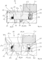
- FIGS. 1a to 4b show different views of flow modulators 10 according to the invention. Identical reference signs are used for identical or similar parts.
- the flow modulator 10 comprises a modulator body 11.
- the modulator body 11 may be part of a housing 12.
- the modulator body 11 may provide a bottom wall 12b of the housing 12.
- the modulator body 11 has a channel 14 providing a flow passage 20 for the fluid. Said channel 14 or flow passage 20 is in communication with an opening 15 acting as outlet port for the fluid.
- a top wall 12c of the housing 12 delimits together with the bottom wall 12b and the side walls 12a an interior space 16 of the housing 12.
- the flow direction of the fluid may also be in the opposite way.
- the opening 15 acts as inlet port for the fluid and the opening 13 acts as outlet port for the fluid.
- the flow modulator 10 further comprises a valve body 17.
- the valve body 17 is positioned within the interior space 16 of the housing 12.
- the valve body 17 has an opening 18 providing another flow passage 19 for the fluid.
- the flow modulator 10 further comprises an actuator 21.
- the actuator 21 may be an electrical motor like a stepper motor.
- valve body 17 is rotatably displaceable relative to the modulator body 11 to modulate the fluid flow.
- the fluid flow is modulated by changing the overlap between the opening 18 or flow passage 19 of the valve body 17 and the channel 14 of flow passage 20 of the modulator body 11.
- the flow modulator 10 further comprises a gear transmission 22.
- An input side of the gear transmission 22 is in operative connection with the actuator 21 having a fixed axis of rotation 23.
- An output side of the gear transmission 22 is in operative connection with the valve body 17 having a translationally displaceable axis of rotation 24.
- the valve body 17 has a guide pin 25 being positioned in the axis of rotation 24 of the valve body 17.
- the modulator body 11 has a guide groove 26 for the guide pin 25 of the valve body 17.
- the guide groove 26 is configured to allow a rotational displacement of the valve body 17 relative to the modulator body 11.
- the guide groove 26 is further configured to allow a translational displacement of the valve body 17 relative to the modulator body 11 in a distance direction X of the axis of rotation 23 of the actuator 21 and the axis of rotation 24 of the valve body 17.
- the guide groove 26 is further configured to prevent a translational displacement of the valve body 17 relative to the modulator body 11 diagonal and/or orthogonal to said distance direction X of the axis of rotation 23 of the actuator 11 and the axis of rotation 24 of the valve body 17.
- the guide pin 25 of the valve body may be a cylinder.
- the guide groove 26 of modulator body 11 may be an oblong hole.
- the dimension of the guide groove 26 in said distance direction X of the axis of rotation 23 of the actuator 21 and the axis of rotation 24 of the valve body 17 is larger than the diameter of the guide pin 25 thereby allowing the translational displacement of the valve body 17 relative to the modulator body11 in said distance direction X.
- the dimension of the guide groove 26 orthogonal to said distance direction X of the axis of rotation 23 of the actuator 21 and the axis of rotation 24 of the valve body 17 is adapted to the diameter of the guide pin 25 thereby preventing the translational displacement of the valve body 17 relative to the modulator body 11 diagonal and/or orthogonal to said distance direction X.
- the gear transmission 22 comprises a first toothing 27 provided by a drive wheel 28.
- the drive wheel 28 provides or corresponds to the input side of the gear transmission 22.
- the gear transmission 22 further comprises a second toothing 29 provided by the valve body 27.
- the valve body 27 provides or corresponds to the output side of the gear transmission 22.
- the first toothing 27 is in operative connection with the second toothing 29.
- the first toothing 27 and the second toothing 29 comb directly into each other thereby providing a single-stage transmission.
- at least one further toothing between the first toothing 27 and the second toothing 29 a multi-stage transmission may be provided.
- the valve body 27 has a circumferential groove 30.
- the drive wheel 28 connected to the axis of rotation 23 of the actuator 21 is at least partially positioned within said circumferential groove 30.
- the circumferential groove 30 has radial width being configured to allow rotation of the valve body 17 relative to the modulator body 11 around the axis of rotation 24 of the valve body 17 while keeping the first toothing 27 of the drive wheel 28 always in operative connection with the second toothing 29 of the valve body 17.
- the first toothing 27 is provided by a section of the drive wheel 28 that is at least partially positioned within said circumferential groove 30, while the second toothing 29 is provided a wall of the circumferential groove 30, namely by a radial outer wall 30a of the circumferential groove 30.
- the first toothing 27 is provided by a section of the drive wheel 28 that is at least partially positioned within said circumferential groove 30, while the second toothing 29 is provided a wall of the circumferential groove 30, namely by a radial inner wall 30b of the circumferential groove 30.
- the first toothing 27 is provided by a section of the drive wheel 28 that is at positioned outside of said circumferential groove 30, while the second toothing 29 is provided by a wall 31 of the valve body 17, namely as an internal toothing of said wall 31.
- the first toothing 27 is provided by a section of the drive wheel 28 that is at positioned outside of said circumferential groove 30, while the second toothing 29 is provided by a wall 31 of the valve body 17, namely as an external toothing of said wall 31.
- Figures 1a to 4b differ from each other by the technical design of the first toothing 27 and the second toothing 29.
- the first toothing 27 is provided by a section of the drive wheel 28 that is at least partially positioned within said circumferential groove 30 and the second toothing 29 is provided by a wall of the circumferential groove 30.
- the opposite wall of the groove 30 does not have a toothing and is smooth.
- the first toothing 27 is provided by a section of the drive wheel 28 that is positioned outside said circumferential groove 30 and the second toothing 29 is provided a wall 31 of the valve body 17. In these embodiments both opposite walls of the groove 30 are smooth.
- the groove 30 of the valve body 17 has radial width being configured to allow the rotation of the valve body 17 relative to the modulator body 11 around the axis of rotation 24 of the valve body 17 while keeping the first toothing 27 of the drive wheel 28 always in operative connection with the second toothing 29 of the valve body 17.
- the drive wheel 28 bears against a respective wall of the groove 30 depending on the position and/or displacement of the valve body 17.
- the circumferential groove 30 has radial width being configured to provide a radial play between the drive wheel 28 and the valve body 17 allowing the rotation of the valve body 17 relative to the modulator body 11 around the axis of rotation 24 of the valve body 17 while keeping the first toothing 27 of the drive wheel 28 always in operative connection with the second toothing 29 of the valve body 17.
- the translational displacement of the valve body 17 is provided by the interaction of the guide pin 25 of the valve body 17 with the guide groove 26 of the modulator body and by the interaction of the circumferential groove 30 of the valve body 17 with the drive wheel 28.
Landscapes
- Engineering & Computer Science (AREA)
- General Engineering & Computer Science (AREA)
- Mechanical Engineering (AREA)
- Chemical & Material Sciences (AREA)
- Combustion & Propulsion (AREA)
- Electrically Driven Valve-Operating Means (AREA)
- Mechanically-Actuated Valves (AREA)
Description
- The invention relates to a flow modulator for a fluid like combustion gas.
-
DE 40 30 717 A1 discloses a flow modulator for a fluid having a housing and a valve body. The valve body is provided by a foil element. The foil element has an opening for the fluid. The foil element is carried by a driver. The driver and the foil element are both positioned within a chamber of the housing. The driver and the foil element are both linear displaceable within the chamber of the housing thereby changing an overlap between an opening of the housing and the opening of the foil element. -
EP 3 792 531 A1 discloses another flow modulator for a fluid comprising a housing, a modulator body, and a valve body. The modulator body has a flow channel and an opening providing together a flow passage for the fluid. The valve body is provided by a foil element. The foil element has an opening for the fluid. The foil element is rotatable relative to the modulator body to modulate the flow of the fluid by adjusting an overlap between the opening of the valve body and the flow passage of the modulator body. -
US 2011 / 0 180 737 A1 discloses a flow modulator according to the preamble of claim 1. - Against this background, a novel flow modulator for a fluid like combustion gas is provided.
- The novel flow modulator for a fluid like combustion gas according to the present disclosure comprises a modulator body having a channel providing a flow passage for the fluid.
- The novel flow modulator further comprises a valve body having an opening providing another flow passage for the fluid.
- The novel flow modulator further comprises an actuator by which the valve body is rotatably displaceable relative to the modulator body to modulate the fluid flow by changing the overlap between the opening of the valve body and the channel of the modulator body.
- The novel flow modulator further comprises a gear transmission, wherein an input side of the gear transmission is in operative connection with the actuator having a fixed axis of rotation, and wherein an output side of the gear transmission is in operative connection with the valve body having a translationally displaceable axis of rotation.
- The novel flow modulator provides a reliable flow modulation of the fluid. The gear transmission of the flow modulator allows for a tolerance-compensation within the flow modulator, namely to compensate component tolerance of the flow modulator. Simple and inexpensive assembly of the flow modulator is possible. A large resolution of flow resistance is made possible by a respective transmission ratio of the gear transmission.
- The valve body has a guide pin being positioned in the axis of rotation of the valve body, and the modulator body has a guide groove for the guide pin of the valve body, wherein the guide groove is configured to allow a rotational displacement of the valve body relative to the modulator body, is further configured to allow a translational displacement of the valve body relative to the modulator body in a distance direction of the axis of rotation of the actuator and the axis of rotation of the valve body, and is further configured to prevent a translational displacement of the valve body relative to the modulator body diagonal and/or orthogonal to said distance direction of the axis of rotation of the actuator and the axis of rotation of the valve body. The allows for a very favorable tolerance-compensation within the flow modulator.
- Preferably, the the gear transmission comprises a first toothing provided by a drive wheel, the gear transmission comprises a second toothing provided by the valve body, wherein the first toothing is in operative connection with the second toothing. Preferably, the valve body has a circumferential groove, wherein the drive wheel is at least partially positioned within said circumferential groove, and wherein the circumferential groove has radial width being configured to allow rotation of the valve body relative to the modulator body around the axis of rotation of the valve body while keeping the first toothing of the drive wheel always in operative connection with the second toothing of the valve body. This allows a favorable tolerance-compensation within the flow modulator while providing a simple and inexpensive assembly of the flow modulator.
- The first toothing may be provided by a section of the drive wheel that is at least partially positioned within said circumferential groove, while the second toothing is provided by a wall of the circumferential groove. Alternatively, the first toothing is provided by a section of the drive wheel that is positioned outside of said circumferential groove, while the second toothing is provided by a wall of the valve body.
- Preferred developments of the invention are provided by the dependent claims and the description of the drawings. Exemplary embodiments are explained in more detail on the basis of the drawing, in which:
- Figure 1a
- shows a cross section of a flow modulator according to a first embodiment of the invention;
- Figure 1b
- shows another cross section of a flow modulator according to the first embodiment of the invention;
- Figure 1c
- shows another cross section of a flow modulator according to the first embodiment of the invention;
- Figure 1d
- shows a perspective view of a detail of the flow modulator of
Figure 1a to 1c ; - Figure 2a
- shows a cross section of a flow modulator according to a second embodiment of the invention;
- Figure 2b
- shows another cross section of a flow modulator according to the second embodiment of the invention;
- Figure 3a
- shows a cross section of a flow modulator according to a third embodiment of the invention;
- Figure 3b
- shows another cross section of a flow modulator according to the third embodiment of the invention;
- Figure 4a
- shows a cross section of a flow modulator according to a fourth embodiment of the invention;
- Figure 4b
- shows another cross section of a flow modulator according to the fourth embodiment of the invention.
- The present invention relates to a
flow modulator 10 for a fluid, preferably for a gaseous fluid like combustion gas. Theflow modulator 10 is preferably part of a gas burner appliance of a heating system. A flow modulator for a gaseous fluid can also be called gas flow modulator. -
Figures 1a to 4b show different views offlow modulators 10 according to the invention. Identical reference signs are used for identical or similar parts. - The
flow modulator 10 comprises a modulator body 11. - The modulator body 11 may be part of a
housing 12. Thehousing 12, namely aside wall 12a of thehousing 12, provides an opening 13 acting as inlet port for the fluid. The modulator body 11 may provide a bottom wall 12b of thehousing 12. - The modulator body 11 has a channel 14 providing a flow passage 20 for the fluid. Said channel 14 or flow passage 20 is in communication with an opening 15 acting as outlet port for the fluid.
- A
top wall 12c of thehousing 12 delimits together with the bottom wall 12b and theside walls 12a aninterior space 16 of thehousing 12. - It should be noted that the flow direction of the fluid may also be in the opposite way. In this case the opening 15 acts as inlet port for the fluid and the opening 13 acts as outlet port for the fluid.
- The
flow modulator 10 further comprises avalve body 17. Thevalve body 17 is positioned within theinterior space 16 of thehousing 12. Thevalve body 17 has an opening 18 providing another flow passage 19 for the fluid. - The
flow modulator 10 further comprises anactuator 21. Theactuator 21 may be an electrical motor like a stepper motor. - By use of the
actuator 21 thevalve body 17 is rotatably displaceable relative to the modulator body 11 to modulate the fluid flow. The fluid flow is modulated by changing the overlap between the opening 18 or flow passage 19 of thevalve body 17 and the channel 14 of flow passage 20 of the modulator body 11. - The
flow modulator 10 further comprises agear transmission 22. - An input side of the
gear transmission 22 is in operative connection with theactuator 21 having a fixed axis ofrotation 23. - An output side of the
gear transmission 22 is in operative connection with thevalve body 17 having a translationally displaceable axis ofrotation 24. - The
valve body 17 has aguide pin 25 being positioned in the axis ofrotation 24 of thevalve body 17. The modulator body 11 has aguide groove 26 for theguide pin 25 of thevalve body 17. - The
guide groove 26 is configured to allow a rotational displacement of thevalve body 17 relative to the modulator body 11. - The
guide groove 26 is further configured to allow a translational displacement of thevalve body 17 relative to the modulator body 11 in a distance direction X of the axis ofrotation 23 of theactuator 21 and the axis ofrotation 24 of thevalve body 17. - However, the
guide groove 26 is further configured to prevent a translational displacement of thevalve body 17 relative to the modulator body 11 diagonal and/or orthogonal to said distance direction X of the axis ofrotation 23 of the actuator 11 and the axis ofrotation 24 of thevalve body 17. - The
guide pin 25 of the valve body may be a cylinder. Theguide groove 26 of modulator body 11 may be an oblong hole. - The dimension of the
guide groove 26 in said distance direction X of the axis ofrotation 23 of theactuator 21 and the axis ofrotation 24 of thevalve body 17 is larger than the diameter of theguide pin 25 thereby allowing the translational displacement of thevalve body 17 relative to the modulator body11 in said distance direction X. - The dimension of the
guide groove 26 orthogonal to said distance direction X of the axis ofrotation 23 of theactuator 21 and the axis ofrotation 24 of thevalve body 17 is adapted to the diameter of theguide pin 25 thereby preventing the translational displacement of thevalve body 17 relative to the modulator body 11 diagonal and/or orthogonal to said distance direction X. - The
gear transmission 22 comprises afirst toothing 27 provided by adrive wheel 28. Thedrive wheel 28 provides or corresponds to the input side of thegear transmission 22. - The
gear transmission 22 further comprises asecond toothing 29 provided by thevalve body 27. Thevalve body 27 provides or corresponds to the output side of thegear transmission 22. - The
first toothing 27 is in operative connection with thesecond toothing 29. Thefirst toothing 27 and thesecond toothing 29 comb directly into each other thereby providing a single-stage transmission. However, by using at least one further toothing between thefirst toothing 27 and the second toothing 29 a multi-stage transmission may be provided. - The
valve body 27 has acircumferential groove 30. Thedrive wheel 28 connected to the axis ofrotation 23 of theactuator 21 is at least partially positioned within saidcircumferential groove 30. - The
circumferential groove 30 has radial width being configured to allow rotation of thevalve body 17 relative to the modulator body 11 around the axis ofrotation 24 of thevalve body 17 while keeping thefirst toothing 27 of thedrive wheel 28 always in operative connection with thesecond toothing 29 of thevalve body 17. - In the embodiment of
Figures 1a to 1d , thefirst toothing 27 is provided by a section of thedrive wheel 28 that is at least partially positioned within saidcircumferential groove 30, while thesecond toothing 29 is provided a wall of thecircumferential groove 30, namely by a radialouter wall 30a of thecircumferential groove 30. - In the embodiment of
Figures 2a and 2b , thefirst toothing 27 is provided by a section of thedrive wheel 28 that is at least partially positioned within saidcircumferential groove 30, while thesecond toothing 29 is provided a wall of thecircumferential groove 30, namely by a radial inner wall 30b of thecircumferential groove 30. - In the embodiment of
Figures 3a and 3b , thefirst toothing 27 is provided by a section of thedrive wheel 28 that is at positioned outside of saidcircumferential groove 30, while thesecond toothing 29 is provided by awall 31 of thevalve body 17, namely as an internal toothing of saidwall 31. - In the embodiment of
Figures 4a and 4b , thefirst toothing 27 is provided by a section of thedrive wheel 28 that is at positioned outside of saidcircumferential groove 30, while thesecond toothing 29 is provided by awall 31 of thevalve body 17, namely as an external toothing of saidwall 31. - The embodiments of
Figures 1a to 4b differ from each other by the technical design of thefirst toothing 27 and thesecond toothing 29. - In the embodiment of
Figures 1a to 1d and in the embodiment ofFigures 2a and 2b thefirst toothing 27 is provided by a section of thedrive wheel 28 that is at least partially positioned within saidcircumferential groove 30 and thesecond toothing 29 is provided by a wall of thecircumferential groove 30. The opposite wall of thegroove 30 does not have a toothing and is smooth. In the embodiment ofFigures 3a and 3b and in the embodiment ofFigures 4a and 4b thefirst toothing 27 is provided by a section of thedrive wheel 28 that is positioned outside saidcircumferential groove 30 and thesecond toothing 29 is provided awall 31 of thevalve body 17. In these embodiments both opposite walls of thegroove 30 are smooth. - Nevertheless, in all embodiments the
groove 30 of thevalve body 17 has radial width being configured to allow the rotation of thevalve body 17 relative to the modulator body 11 around the axis ofrotation 24 of thevalve body 17 while keeping thefirst toothing 27 of thedrive wheel 28 always in operative connection with thesecond toothing 29 of thevalve body 17. Thedrive wheel 28 bears against a respective wall of thegroove 30 depending on the position and/or displacement of thevalve body 17. - The
circumferential groove 30 has radial width being configured to provide a radial play between thedrive wheel 28 and thevalve body 17 allowing the rotation of thevalve body 17 relative to the modulator body 11 around the axis ofrotation 24 of thevalve body 17 while keeping thefirst toothing 27 of thedrive wheel 28 always in operative connection with thesecond toothing 29 of thevalve body 17. - The translational displacement of the
valve body 17 is provided by the interaction of theguide pin 25 of thevalve body 17 with theguide groove 26 of the modulator body and by the interaction of thecircumferential groove 30 of thevalve body 17 with thedrive wheel 28. -
- 10
- flow modulator
- 11
- modulator body
- 12
- housing
- 12a
- side wall
- 12b
- bottom wall
- 12c
- top wall
- 13
- opening
- 14
- channel
- 15
- opening
- 16
- interior space
- 17
- valve body
- 18
- opening
- 19
- flow passage
- 20
- flow passage
- 21
- actuator
- 22
- gear transmission
- 23
- axis of rotation
- 24
- axis of rotation
- 25
- guide pin
- 26
- guide groove
- 27
- first toothing
- 28
- drive wheel
- 29
- second toothing
- 30
- groove
- 30a
- radial outer wall
- 30b
- radial inner wall
- 31
- wall
Claims (10)
- Flow modulator (10) for a fluid like combustion gas, comprising:a modulator body (11) having a channel (14) providing a flow passage (20) for the fluid;a valve body (17) having an opening (18) providing another flow passage (19) for the fluid;an actuator (21) by which the valve body (17) is rotatably displaceable relative to the modulator body (11) to modulate the fluid flow by changing the overlap between the opening (18) or flow passage (19) of the valve body (17) and the channel (14) or flow passage (20) of the modulator body (11);a gear transmission (22),
wherein an input side of the gear transmission (22) is in operative connection with the actuator (21) having a fixed axis of rotation (23),whereinan output side of the gear transmission (22) is in operative connection with the valve body (17) having a translationally displaceable axis of rotation (24),and wherein the valve body (17) has a guide pin (25) being positioned in the axis of rotation (24) of the valve body (17), characterised in thatthe modulator body (11) has a guide groove (26) for the guide pin (15) of the valve body (17), wherein the guide groove (26) is configured toallow a rotational displacement of the valve body (17) relative to the modulator body (11),allow a translational displacement of the valve body (17) relative to the modulator body (11) in a distance direction (X) of the axis of rotation (23) of the actuator (21) and the axis of rotation (24) of the valve body (17),prevent a translational displacement of the valve body (17) relative to the modulator body (11) diagonal and/or orthogonal to said distance direction (X) of the axis of rotation (23) of the actuator (21) and the axis of rotation (24) of the valve body (17). - Flow modulator as claimed in claim 1, characterized in thatthe guide pin (25) of the valve body (17) is a cylinder,the guide groove (26) of modulator body (11) is an oblong hole.
- Flow modulator as claimed in claim 1 or 2, characterized in thatthe gear transmission (22) comprises a first toothing (27) provided by a drive wheel (28),the gear transmission (22) comprises a second toothing (29) provided by the valve body (17),the first toothing (27) is in operative connection with the second toothing (29).
- Flow modulator as claimed in claim 3, characterized in thatthe valve body (17) has a circumferential groove (30),the drive wheel (18) is at least partially positioned within said circumferential groove (30),the circumferential groove (30) has radial width being configured to allow rotation of the valve body (17) around the axis of rotation of the valve body (17) while keeping the first toothing (27) of the drive wheel (28) always in operative connection with the second toothing (29) of the valve body (17).
- Flow modulator as claimed in claim 4, characterized in thatthe first toothing (27) is provided by a section of the drive wheel (28) that is at least partially positioned within said circumferential groove (30),the second toothing (29) is provided by a wall of the circumferential groove (30).
- Flow modulator as claimed in claim 5, characterized in that
the second toothing (29) is provided by a radial inner wall (30b) of the circumferential groove (30). - Flow modulator as claimed in claim 5, characterized in that
the second toothing (29) is provided by a radial outer wall (30a) of the circumferential groove (30). - Flow modulator as claimed in claim 4, characterized in thatthe first toothing (27) is provided by a section of the drive wheel (28) that is at positioned outside of said circumferential groove (30),the second toothing (29) is provided by a wall (31) of the valve body (17).
- Flow modulator as claimed in claim 8, characterized in that
the second toothing (29) is provided as an internal toothing. - Flow modulator as claimed in claim 8, characterized in that
the second toothing (29) is provided as an external toothing.
Priority Applications (3)
| Application Number | Priority Date | Filing Date | Title |
|---|---|---|---|
| EP21176651.4A EP4095420B1 (en) | 2021-05-28 | 2021-05-28 | Flow modulator for a fluid |
| PCT/EP2022/063911 WO2022248408A1 (en) | 2021-05-28 | 2022-05-23 | Flow modulator for a fluid |
| US18/560,345 US20240247725A1 (en) | 2021-05-28 | 2022-05-23 | Flow modulator for a fluid |
Applications Claiming Priority (1)
| Application Number | Priority Date | Filing Date | Title |
|---|---|---|---|
| EP21176651.4A EP4095420B1 (en) | 2021-05-28 | 2021-05-28 | Flow modulator for a fluid |
Publications (2)
| Publication Number | Publication Date |
|---|---|
| EP4095420A1 EP4095420A1 (en) | 2022-11-30 |
| EP4095420B1 true EP4095420B1 (en) | 2024-11-20 |
Family
ID=76181015
Family Applications (1)
| Application Number | Title | Priority Date | Filing Date |
|---|---|---|---|
| EP21176651.4A Active EP4095420B1 (en) | 2021-05-28 | 2021-05-28 | Flow modulator for a fluid |
Country Status (3)
| Country | Link |
|---|---|
| US (1) | US20240247725A1 (en) |
| EP (1) | EP4095420B1 (en) |
| WO (1) | WO2022248408A1 (en) |
Families Citing this family (1)
| Publication number | Priority date | Publication date | Assignee | Title |
|---|---|---|---|---|
| EP4033148B1 (en) * | 2021-01-25 | 2023-11-01 | Pittway Sarl | Method and controller for operating a gas burner appliance |
Family Cites Families (5)
| Publication number | Priority date | Publication date | Assignee | Title |
|---|---|---|---|---|
| DE3701167C1 (en) * | 1987-01-16 | 1988-04-28 | Triumph Adler Ag | Device for storing a gear transmission |
| DE4030717A1 (en) | 1990-09-28 | 1992-04-02 | Bosch Gmbh Robert | Throttle check valve - has movable valve element with aperture formed from deformable foil and moving, during throttling, into play free contact |
| DE102008042947A1 (en) * | 2008-10-20 | 2010-04-22 | Robert Bosch Gmbh | Valve for controlling volume flows |
| WO2020181617A1 (en) * | 2019-03-11 | 2020-09-17 | 杭州天铭科技股份有限公司 | Adjustment apparatus, adjuster, and shock absorber |
| EP4269873A3 (en) | 2019-09-13 | 2023-11-22 | Pittway Sarl | Flow modulator for a fluid |
-
2021
- 2021-05-28 EP EP21176651.4A patent/EP4095420B1/en active Active
-
2022
- 2022-05-23 US US18/560,345 patent/US20240247725A1/en active Pending
- 2022-05-23 WO PCT/EP2022/063911 patent/WO2022248408A1/en not_active Ceased
Also Published As
| Publication number | Publication date |
|---|---|
| EP4095420A1 (en) | 2022-11-30 |
| WO2022248408A1 (en) | 2022-12-01 |
| US20240247725A1 (en) | 2024-07-25 |
Similar Documents
| Publication | Publication Date | Title |
|---|---|---|
| KR100504643B1 (en) | Device for hydraulic rotational angle adjustment of a shaft relative to a drive wheel | |
| JP7228694B2 (en) | Ball valve | |
| US11598441B2 (en) | Coolant control valve with non-coaxial rotary valve bodies | |
| US8562463B2 (en) | Belt type continuously variable transmission | |
| EP3792531B1 (en) | Flow modulator for a fluid | |
| US8197374B2 (en) | Automatic transmission | |
| KR20030032008A (en) | Valve drive device | |
| US20240247725A1 (en) | Flow modulator for a fluid | |
| KR20170006273A (en) | Multidirection multivalve for automotive | |
| CN101600856A (en) | Combined locking and rotation angle limiting device for a camshaft adjuster | |
| US6206574B1 (en) | Ball bearing and method of assembling the same | |
| US8267799B2 (en) | Device for damping vibrations | |
| US20210388744A1 (en) | Recirculating hydraulic fluid control valve | |
| EP4411184A1 (en) | Multi-way valve | |
| US11560813B2 (en) | Recirculating hydraulic fluid control valve | |
| EP1731791B1 (en) | Rotary damper | |
| EP0028556B1 (en) | Hydraulic control valve | |
| CN111350844B (en) | Ball valve | |
| ITMI932476A1 (en) | HYDRAULIC REGULATION DEVICE | |
| CN103306772B (en) | Camshaft adjuster | |
| JP2020159440A (en) | Revolver switching valve | |
| KR200157998Y1 (en) | Manual valve sealing cap fixing structure of automatic transmission for automobile | |
| EP0905005B1 (en) | Rack-pinion type power steering apparatus | |
| US11899474B2 (en) | Temperature sensor for coolant control valve | |
| KR100348071B1 (en) | oil pump mounting structure for automatic transmission of automobile |
Legal Events
| Date | Code | Title | Description |
|---|---|---|---|
| PUAI | Public reference made under article 153(3) epc to a published international application that has entered the european phase |
Free format text: ORIGINAL CODE: 0009012 |
|
| STAA | Information on the status of an ep patent application or granted ep patent |
Free format text: STATUS: THE APPLICATION HAS BEEN PUBLISHED |
|
| AK | Designated contracting states |
Kind code of ref document: A1 Designated state(s): AL AT BE BG CH CY CZ DE DK EE ES FI FR GB GR HR HU IE IS IT LI LT LU LV MC MK MT NL NO PL PT RO RS SE SI SK SM TR |
|
| STAA | Information on the status of an ep patent application or granted ep patent |
Free format text: STATUS: REQUEST FOR EXAMINATION WAS MADE |
|
| 17P | Request for examination filed |
Effective date: 20230523 |
|
| RBV | Designated contracting states (corrected) |
Designated state(s): AL AT BE BG CH CY CZ DE DK EE ES FI FR GB GR HR HU IE IS IT LI LT LU LV MC MK MT NL NO PL PT RO RS SE SI SK SM TR |
|
| P01 | Opt-out of the competence of the unified patent court (upc) registered |
Effective date: 20230827 |
|
| GRAP | Despatch of communication of intention to grant a patent |
Free format text: ORIGINAL CODE: EPIDOSNIGR1 |
|
| GRAP | Despatch of communication of intention to grant a patent |
Free format text: ORIGINAL CODE: EPIDOSNIGR1 |
|
| STAA | Information on the status of an ep patent application or granted ep patent |
Free format text: STATUS: GRANT OF PATENT IS INTENDED |
|
| INTG | Intention to grant announced |
Effective date: 20240614 |
|
| GRAS | Grant fee paid |
Free format text: ORIGINAL CODE: EPIDOSNIGR3 |
|
| GRAA | (expected) grant |
Free format text: ORIGINAL CODE: 0009210 |
|
| STAA | Information on the status of an ep patent application or granted ep patent |
Free format text: STATUS: THE PATENT HAS BEEN GRANTED |
|
| AK | Designated contracting states |
Kind code of ref document: B1 Designated state(s): AL AT BE BG CH CY CZ DE DK EE ES FI FR GB GR HR HU IE IS IT LI LT LU LV MC MK MT NL NO PL PT RO RS SE SI SK SM TR |
|
| REG | Reference to a national code |
Ref country code: GB Ref legal event code: FG4D |
|
| REG | Reference to a national code |
Ref country code: CH Ref legal event code: EP |
|
| REG | Reference to a national code |
Ref country code: DE Ref legal event code: R096 Ref document number: 602021021981 Country of ref document: DE |
|
| REG | Reference to a national code |
Ref country code: IE Ref legal event code: FG4D |
|
| REG | Reference to a national code |
Ref country code: LT Ref legal event code: MG9D |
|
| REG | Reference to a national code |
Ref country code: NL Ref legal event code: MP Effective date: 20241120 |
|
| PG25 | Lapsed in a contracting state [announced via postgrant information from national office to epo] |
Ref country code: IS Free format text: LAPSE BECAUSE OF FAILURE TO SUBMIT A TRANSLATION OF THE DESCRIPTION OR TO PAY THE FEE WITHIN THE PRESCRIBED TIME-LIMIT Effective date: 20250320 Ref country code: PT Free format text: LAPSE BECAUSE OF FAILURE TO SUBMIT A TRANSLATION OF THE DESCRIPTION OR TO PAY THE FEE WITHIN THE PRESCRIBED TIME-LIMIT Effective date: 20250320 Ref country code: HR Free format text: LAPSE BECAUSE OF FAILURE TO SUBMIT A TRANSLATION OF THE DESCRIPTION OR TO PAY THE FEE WITHIN THE PRESCRIBED TIME-LIMIT Effective date: 20241120 |
|
| PG25 | Lapsed in a contracting state [announced via postgrant information from national office to epo] |
Ref country code: FI Free format text: LAPSE BECAUSE OF FAILURE TO SUBMIT A TRANSLATION OF THE DESCRIPTION OR TO PAY THE FEE WITHIN THE PRESCRIBED TIME-LIMIT Effective date: 20241120 Ref country code: NL Free format text: LAPSE BECAUSE OF FAILURE TO SUBMIT A TRANSLATION OF THE DESCRIPTION OR TO PAY THE FEE WITHIN THE PRESCRIBED TIME-LIMIT Effective date: 20241120 |
|
| REG | Reference to a national code |
Ref country code: AT Ref legal event code: MK05 Ref document number: 1743837 Country of ref document: AT Kind code of ref document: T Effective date: 20241120 |
|
| PG25 | Lapsed in a contracting state [announced via postgrant information from national office to epo] |
Ref country code: BG Free format text: LAPSE BECAUSE OF FAILURE TO SUBMIT A TRANSLATION OF THE DESCRIPTION OR TO PAY THE FEE WITHIN THE PRESCRIBED TIME-LIMIT Effective date: 20241120 |
|
| PG25 | Lapsed in a contracting state [announced via postgrant information from national office to epo] |
Ref country code: ES Free format text: LAPSE BECAUSE OF FAILURE TO SUBMIT A TRANSLATION OF THE DESCRIPTION OR TO PAY THE FEE WITHIN THE PRESCRIBED TIME-LIMIT Effective date: 20241120 |
|
| PG25 | Lapsed in a contracting state [announced via postgrant information from national office to epo] |
Ref country code: NO Free format text: LAPSE BECAUSE OF FAILURE TO SUBMIT A TRANSLATION OF THE DESCRIPTION OR TO PAY THE FEE WITHIN THE PRESCRIBED TIME-LIMIT Effective date: 20250220 |
|
| PG25 | Lapsed in a contracting state [announced via postgrant information from national office to epo] |
Ref country code: LV Free format text: LAPSE BECAUSE OF FAILURE TO SUBMIT A TRANSLATION OF THE DESCRIPTION OR TO PAY THE FEE WITHIN THE PRESCRIBED TIME-LIMIT Effective date: 20241120 Ref country code: GR Free format text: LAPSE BECAUSE OF FAILURE TO SUBMIT A TRANSLATION OF THE DESCRIPTION OR TO PAY THE FEE WITHIN THE PRESCRIBED TIME-LIMIT Effective date: 20250221 Ref country code: AT Free format text: LAPSE BECAUSE OF FAILURE TO SUBMIT A TRANSLATION OF THE DESCRIPTION OR TO PAY THE FEE WITHIN THE PRESCRIBED TIME-LIMIT Effective date: 20241120 |
|
| PG25 | Lapsed in a contracting state [announced via postgrant information from national office to epo] |
Ref country code: PL Free format text: LAPSE BECAUSE OF FAILURE TO SUBMIT A TRANSLATION OF THE DESCRIPTION OR TO PAY THE FEE WITHIN THE PRESCRIBED TIME-LIMIT Effective date: 20241120 |
|
| PG25 | Lapsed in a contracting state [announced via postgrant information from national office to epo] |
Ref country code: RS Free format text: LAPSE BECAUSE OF FAILURE TO SUBMIT A TRANSLATION OF THE DESCRIPTION OR TO PAY THE FEE WITHIN THE PRESCRIBED TIME-LIMIT Effective date: 20250220 |
|
| PG25 | Lapsed in a contracting state [announced via postgrant information from national office to epo] |
Ref country code: SM Free format text: LAPSE BECAUSE OF FAILURE TO SUBMIT A TRANSLATION OF THE DESCRIPTION OR TO PAY THE FEE WITHIN THE PRESCRIBED TIME-LIMIT Effective date: 20241120 |
|
| PG25 | Lapsed in a contracting state [announced via postgrant information from national office to epo] |
Ref country code: DK Free format text: LAPSE BECAUSE OF FAILURE TO SUBMIT A TRANSLATION OF THE DESCRIPTION OR TO PAY THE FEE WITHIN THE PRESCRIBED TIME-LIMIT Effective date: 20241120 |
|
| PG25 | Lapsed in a contracting state [announced via postgrant information from national office to epo] |
Ref country code: EE Free format text: LAPSE BECAUSE OF FAILURE TO SUBMIT A TRANSLATION OF THE DESCRIPTION OR TO PAY THE FEE WITHIN THE PRESCRIBED TIME-LIMIT Effective date: 20241120 |
|
| PG25 | Lapsed in a contracting state [announced via postgrant information from national office to epo] |
Ref country code: RO Free format text: LAPSE BECAUSE OF FAILURE TO SUBMIT A TRANSLATION OF THE DESCRIPTION OR TO PAY THE FEE WITHIN THE PRESCRIBED TIME-LIMIT Effective date: 20241120 |
|
| PG25 | Lapsed in a contracting state [announced via postgrant information from national office to epo] |
Ref country code: SK Free format text: LAPSE BECAUSE OF FAILURE TO SUBMIT A TRANSLATION OF THE DESCRIPTION OR TO PAY THE FEE WITHIN THE PRESCRIBED TIME-LIMIT Effective date: 20241120 |
|
| PG25 | Lapsed in a contracting state [announced via postgrant information from national office to epo] |
Ref country code: CZ Free format text: LAPSE BECAUSE OF FAILURE TO SUBMIT A TRANSLATION OF THE DESCRIPTION OR TO PAY THE FEE WITHIN THE PRESCRIBED TIME-LIMIT Effective date: 20241120 |
|
| PG25 | Lapsed in a contracting state [announced via postgrant information from national office to epo] |
Ref country code: IT Free format text: LAPSE BECAUSE OF FAILURE TO SUBMIT A TRANSLATION OF THE DESCRIPTION OR TO PAY THE FEE WITHIN THE PRESCRIBED TIME-LIMIT Effective date: 20241120 |
|
| REG | Reference to a national code |
Ref country code: DE Ref legal event code: R097 Ref document number: 602021021981 Country of ref document: DE |
|
| PG25 | Lapsed in a contracting state [announced via postgrant information from national office to epo] |
Ref country code: SE Free format text: LAPSE BECAUSE OF FAILURE TO SUBMIT A TRANSLATION OF THE DESCRIPTION OR TO PAY THE FEE WITHIN THE PRESCRIBED TIME-LIMIT Effective date: 20241120 |
|
| PLBE | No opposition filed within time limit |
Free format text: ORIGINAL CODE: 0009261 |
|
| STAA | Information on the status of an ep patent application or granted ep patent |
Free format text: STATUS: NO OPPOSITION FILED WITHIN TIME LIMIT |
|
| 26N | No opposition filed |
Effective date: 20250821 |
|
| REG | Reference to a national code |
Ref country code: CH Ref legal event code: H13 Free format text: ST27 STATUS EVENT CODE: U-0-0-H10-H13 (AS PROVIDED BY THE NATIONAL OFFICE) Effective date: 20251223 |
|
| PGFP | Annual fee paid to national office [announced via postgrant information from national office to epo] |
Ref country code: DE Payment date: 20251014 Year of fee payment: 5 |
|
| PG25 | Lapsed in a contracting state [announced via postgrant information from national office to epo] |
Ref country code: LU Free format text: LAPSE BECAUSE OF NON-PAYMENT OF DUE FEES Effective date: 20250528 |
|
| PG25 | Lapsed in a contracting state [announced via postgrant information from national office to epo] |
Ref country code: CH Free format text: LAPSE BECAUSE OF NON-PAYMENT OF DUE FEES Effective date: 20250531 |
|
| GBPC | Gb: european patent ceased through non-payment of renewal fee |
Effective date: 20250528 |
|
| REG | Reference to a national code |
Ref country code: BE Ref legal event code: MM Effective date: 20250531 |
|
| PG25 | Lapsed in a contracting state [announced via postgrant information from national office to epo] |
Ref country code: MC Free format text: LAPSE BECAUSE OF FAILURE TO SUBMIT A TRANSLATION OF THE DESCRIPTION OR TO PAY THE FEE WITHIN THE PRESCRIBED TIME-LIMIT Effective date: 20241120 |
|
| PG25 | Lapsed in a contracting state [announced via postgrant information from national office to epo] |
Ref country code: GB Free format text: LAPSE BECAUSE OF NON-PAYMENT OF DUE FEES Effective date: 20250528 |
|
| PG25 | Lapsed in a contracting state [announced via postgrant information from national office to epo] |
Ref country code: IE Free format text: LAPSE BECAUSE OF NON-PAYMENT OF DUE FEES Effective date: 20250528 |
|
| PG25 | Lapsed in a contracting state [announced via postgrant information from national office to epo] |
Ref country code: BE Free format text: LAPSE BECAUSE OF NON-PAYMENT OF DUE FEES Effective date: 20250531 |
|
| PG25 | Lapsed in a contracting state [announced via postgrant information from national office to epo] |
Ref country code: FR Free format text: LAPSE BECAUSE OF NON-PAYMENT OF DUE FEES Effective date: 20250531 |