EP4095303A1 - Laundry treating apparatus - Google Patents
Laundry treating apparatus Download PDFInfo
- Publication number
- EP4095303A1 EP4095303A1 EP22175993.9A EP22175993A EP4095303A1 EP 4095303 A1 EP4095303 A1 EP 4095303A1 EP 22175993 A EP22175993 A EP 22175993A EP 4095303 A1 EP4095303 A1 EP 4095303A1
- Authority
- EP
- European Patent Office
- Prior art keywords
- laundry treating
- dryer
- refresher
- heating device
- washing machine
- Prior art date
- Legal status (The legal status is an assumption and is not a legal conclusion. Google has not performed a legal analysis and makes no representation as to the accuracy of the status listed.)
- Granted
Links
Images









Classifications
-
- D—TEXTILES; PAPER
- D06—TREATMENT OF TEXTILES OR THE LIKE; LAUNDERING; FLEXIBLE MATERIALS NOT OTHERWISE PROVIDED FOR
- D06F—LAUNDERING, DRYING, IRONING, PRESSING OR FOLDING TEXTILE ARTICLES
- D06F29/00—Combinations of a washing machine with other separate apparatus in a common frame or the like, e.g. with rinsing apparatus
-
- D—TEXTILES; PAPER
- D06—TREATMENT OF TEXTILES OR THE LIKE; LAUNDERING; FLEXIBLE MATERIALS NOT OTHERWISE PROVIDED FOR
- D06F—LAUNDERING, DRYING, IRONING, PRESSING OR FOLDING TEXTILE ARTICLES
- D06F58/00—Domestic laundry dryers
- D06F58/32—Control of operations performed in domestic laundry dryers
- D06F58/34—Control of operations performed in domestic laundry dryers characterised by the purpose or target of the control
- D06F58/36—Control of operational steps, e.g. for optimisation or improvement of operational steps depending on the condition of the laundry
- D06F58/38—Control of operational steps, e.g. for optimisation or improvement of operational steps depending on the condition of the laundry of drying, e.g. to achieve the target humidity
-
- D—TEXTILES; PAPER
- D06—TREATMENT OF TEXTILES OR THE LIKE; LAUNDERING; FLEXIBLE MATERIALS NOT OTHERWISE PROVIDED FOR
- D06F—LAUNDERING, DRYING, IRONING, PRESSING OR FOLDING TEXTILE ARTICLES
- D06F25/00—Washing machines with receptacles, e.g. perforated, having a rotary movement, e.g. oscillatory movement, the receptacle serving both for washing and for centrifugally separating water from the laundry and having further drying means, e.g. using hot air
-
- D—TEXTILES; PAPER
- D06—TREATMENT OF TEXTILES OR THE LIKE; LAUNDERING; FLEXIBLE MATERIALS NOT OTHERWISE PROVIDED FOR
- D06F—LAUNDERING, DRYING, IRONING, PRESSING OR FOLDING TEXTILE ARTICLES
- D06F29/00—Combinations of a washing machine with other separate apparatus in a common frame or the like, e.g. with rinsing apparatus
- D06F29/005—Combinations of a washing machine with other separate apparatus in a common frame or the like, e.g. with rinsing apparatus the other separate apparatus being a drying appliance
-
- D—TEXTILES; PAPER
- D06—TREATMENT OF TEXTILES OR THE LIKE; LAUNDERING; FLEXIBLE MATERIALS NOT OTHERWISE PROVIDED FOR
- D06F—LAUNDERING, DRYING, IRONING, PRESSING OR FOLDING TEXTILE ARTICLES
- D06F33/00—Control of operations performed in washing machines or washer-dryers
- D06F33/30—Control of washing machines characterised by the purpose or target of the control
- D06F33/32—Control of operational steps, e.g. optimisation or improvement of operational steps depending on the condition of the laundry
-
- D—TEXTILES; PAPER
- D06—TREATMENT OF TEXTILES OR THE LIKE; LAUNDERING; FLEXIBLE MATERIALS NOT OTHERWISE PROVIDED FOR
- D06F—LAUNDERING, DRYING, IRONING, PRESSING OR FOLDING TEXTILE ARTICLES
- D06F39/00—Details of washing machines not specific to a single type of machines covered by groups D06F9/00 - D06F27/00
- D06F39/04—Heating arrangements
-
- D—TEXTILES; PAPER
- D06—TREATMENT OF TEXTILES OR THE LIKE; LAUNDERING; FLEXIBLE MATERIALS NOT OTHERWISE PROVIDED FOR
- D06F—LAUNDERING, DRYING, IRONING, PRESSING OR FOLDING TEXTILE ARTICLES
- D06F58/00—Domestic laundry dryers
- D06F58/20—General details of domestic laundry dryers
-
- D—TEXTILES; PAPER
- D06—TREATMENT OF TEXTILES OR THE LIKE; LAUNDERING; FLEXIBLE MATERIALS NOT OTHERWISE PROVIDED FOR
- D06F—LAUNDERING, DRYING, IRONING, PRESSING OR FOLDING TEXTILE ARTICLES
- D06F58/00—Domestic laundry dryers
- D06F58/20—General details of domestic laundry dryers
- D06F58/206—Heat pump arrangements
-
- D—TEXTILES; PAPER
- D06—TREATMENT OF TEXTILES OR THE LIKE; LAUNDERING; FLEXIBLE MATERIALS NOT OTHERWISE PROVIDED FOR
- D06F—LAUNDERING, DRYING, IRONING, PRESSING OR FOLDING TEXTILE ARTICLES
- D06F58/00—Domestic laundry dryers
- D06F58/20—General details of domestic laundry dryers
- D06F58/26—Heating arrangements, e.g. gas heating equipment
-
- D—TEXTILES; PAPER
- D06—TREATMENT OF TEXTILES OR THE LIKE; LAUNDERING; FLEXIBLE MATERIALS NOT OTHERWISE PROVIDED FOR
- D06F—LAUNDERING, DRYING, IRONING, PRESSING OR FOLDING TEXTILE ARTICLES
- D06F73/00—Apparatus for smoothing or removing creases from garments or other textile articles by formers, cores, stretchers, or internal frames, with the application of heat or steam
- D06F73/02—Apparatus for smoothing or removing creases from garments or other textile articles by formers, cores, stretchers, or internal frames, with the application of heat or steam having one or more treatment chambers
-
- D—TEXTILES; PAPER
- D06—TREATMENT OF TEXTILES OR THE LIKE; LAUNDERING; FLEXIBLE MATERIALS NOT OTHERWISE PROVIDED FOR
- D06F—LAUNDERING, DRYING, IRONING, PRESSING OR FOLDING TEXTILE ARTICLES
- D06F2103/00—Parameters monitored or detected for the control of domestic laundry washing machines, washer-dryers or laundry dryers
- D06F2103/28—Air properties
- D06F2103/32—Temperature
-
- D—TEXTILES; PAPER
- D06—TREATMENT OF TEXTILES OR THE LIKE; LAUNDERING; FLEXIBLE MATERIALS NOT OTHERWISE PROVIDED FOR
- D06F—LAUNDERING, DRYING, IRONING, PRESSING OR FOLDING TEXTILE ARTICLES
- D06F2103/00—Parameters monitored or detected for the control of domestic laundry washing machines, washer-dryers or laundry dryers
- D06F2103/50—Parameters monitored or detected for the control of domestic laundry washing machines, washer-dryers or laundry dryers related to heat pumps, e.g. pressure or flow rate
-
- D—TEXTILES; PAPER
- D06—TREATMENT OF TEXTILES OR THE LIKE; LAUNDERING; FLEXIBLE MATERIALS NOT OTHERWISE PROVIDED FOR
- D06F—LAUNDERING, DRYING, IRONING, PRESSING OR FOLDING TEXTILE ARTICLES
- D06F2103/00—Parameters monitored or detected for the control of domestic laundry washing machines, washer-dryers or laundry dryers
- D06F2103/54—Parameters monitored or detected for the control of domestic laundry washing machines, washer-dryers or laundry dryers related to blowers or fans
-
- D—TEXTILES; PAPER
- D06—TREATMENT OF TEXTILES OR THE LIKE; LAUNDERING; FLEXIBLE MATERIALS NOT OTHERWISE PROVIDED FOR
- D06F—LAUNDERING, DRYING, IRONING, PRESSING OR FOLDING TEXTILE ARTICLES
- D06F2105/00—Systems or parameters controlled or affected by the control systems of washing machines, washer-dryers or laundry dryers
- D06F2105/16—Air properties
- D06F2105/20—Temperature
-
- D—TEXTILES; PAPER
- D06—TREATMENT OF TEXTILES OR THE LIKE; LAUNDERING; FLEXIBLE MATERIALS NOT OTHERWISE PROVIDED FOR
- D06F—LAUNDERING, DRYING, IRONING, PRESSING OR FOLDING TEXTILE ARTICLES
- D06F2105/00—Systems or parameters controlled or affected by the control systems of washing machines, washer-dryers or laundry dryers
- D06F2105/26—Heat pumps
-
- D—TEXTILES; PAPER
- D06—TREATMENT OF TEXTILES OR THE LIKE; LAUNDERING; FLEXIBLE MATERIALS NOT OTHERWISE PROVIDED FOR
- D06F—LAUNDERING, DRYING, IRONING, PRESSING OR FOLDING TEXTILE ARTICLES
- D06F2105/00—Systems or parameters controlled or affected by the control systems of washing machines, washer-dryers or laundry dryers
- D06F2105/52—Changing sequence of operational steps; Carrying out additional operational steps; Modifying operational steps, e.g. by extending duration of steps
-
- D—TEXTILES; PAPER
- D06—TREATMENT OF TEXTILES OR THE LIKE; LAUNDERING; FLEXIBLE MATERIALS NOT OTHERWISE PROVIDED FOR
- D06F—LAUNDERING, DRYING, IRONING, PRESSING OR FOLDING TEXTILE ARTICLES
- D06F58/00—Domestic laundry dryers
- D06F58/10—Drying cabinets or drying chambers having heating or ventilating means
-
- D—TEXTILES; PAPER
- D06—TREATMENT OF TEXTILES OR THE LIKE; LAUNDERING; FLEXIBLE MATERIALS NOT OTHERWISE PROVIDED FOR
- D06F—LAUNDERING, DRYING, IRONING, PRESSING OR FOLDING TEXTILE ARTICLES
- D06F58/00—Domestic laundry dryers
- D06F58/20—General details of domestic laundry dryers
- D06F58/203—Laundry conditioning arrangements
Definitions
- the present disclosure relates to a laundry treating apparatus, and more particularly to a laundry treating apparatus including a plurality of laundry treating machines.
- Laundry treating machines such as washing machines, dryers, and refreshers, are installed in different spaces, such as a kitchen, a utility room, and an outdoor space, according to usage in a residential space.
- Korean Laid-Open Patent Publication No. 10-2020-0109194 discloses a washing machine.
- the washing machine washes laundry by supplying water and detergent into a tub and a drum and by rotating the drum in which the laundry is placed.
- water from an external water source is supplied into the tub or the drum, and a pump is used to circulate the water in the tub to the drum or to discharge the water in the tub to the outside.
- the washing machine is generally installed in the kitchen or the utility room for the supply and discharge of water.
- the washing machine separately includes a heater for heating air, a blower fan, and a steam generator, to dry or sterilize the laundry.
- Korean Patent No. 10-2120993 discloses a dryer.
- the dryer may dry the laundry, placed in the drum, by heating air using a heating means and a blower fan and by supplying the heated air into the drum.
- the dryer is generally disposed adjacent to the washing machine, so as to dry the washed laundry and to allow a user to easily load the laundry containing moisture into the dryer.
- the dryer may sterilize the laundry or may relieve wrinkles from the laundry. Water may be supplied into the dryer for generating the steam, and water not changed into steam may be reused or may be discharged to the outside. Further, in order to deodorize the dried laundry, the dryer may further have a deodorization function for filtering the circulated air.
- Korean Patent No. 10-2254903 discloses a refresher.
- the refresher may perform functions, such as drying, deodorizing, de-wrinkling, de-static and/or sterilization (hereinafter referred to as "refreshing").
- the refresher is used for treating clothes, such as suits and coats, which are frequently used by a user after washing.
- clothes such as suits and coats
- the refresher may be installed adjacent to the wardrobe, or may be installed instead of the wardrobe, in a dressing room, a living room, or a bedroom.
- the refresher may also be used for all washable items, such as shoes, socks, gloves, hats, scarves, etc., which are worn by users, as well as dolls, towels, blankets, etc., which are frequently used by users.
- the existing laundry treating machines which are installed in different spaces, have a problem in that users need to move the laundry items, which are sorted by the user, to the respective laundry treating machines performing corresponding laundry treating processes, thereby requiring a longer workflow, and making the laundry treating processes uncomfortable.
- each of the existing laundry treating machines for treating the laundry using hot air and steam separately requires water supply equipment, drainage equipment, an air heater, a steam generator, a pump, a blower fan, an air passage, a steam passage, etc., thereby causing a problem in that a space for receiving clothes is reduced.
- each of the machines includes the heater, the steam generator, etc., causing a problem in that costs and energy consumption of the entire system may increase.
- the existing laundry treating machines for treating the laundry by using hot air and steam are inefficient in that the laundry treating machines perform operations without considering cycles of other machines.
- a laundry treating apparatus includes a plurality of laundry treating machines. Further, the laundry treating apparatus may include a heating device for heating air supplied to the plurality of laundry treating machines.
- the laundry treating apparatus may provide multi-purpose laundry treating machines in the same space, and may heat the air supplied to the plurality of laundry treating machines by using a single heating device.
- the laundry treating apparatus may minimize the effect of a cycle status of each laundry treating machine on another laundry treating machine.
- the laundry treating apparatus may include a heating device that is operated based on a cycle status of any one laundry treating machine.
- the heating device may be disposed in one of the laundry treating machines or may be disposed at an upper portion or a lower portion of the laundry treating machine.
- the laundry treating machines may include: a dryer including a first cabinet, and a first drum rotatably mounted in the first cabinet and receiving laundry; a washing machine including a second cabinet, a tub disposed in the second cabinet, and a second drum rotatably mounted in the tub and receiving laundry; and a laundry care device including a third cabinet and having an inner space for receiving laundry.
- the laundry care device may be a refresher.
- the first to third cabinets may be formed independently of each other and may be connected to be integrally formed with each other, or two of the cabinets may be integrally formed with each other to be connected to another cabinet, or the three cabinets may be integrally formed with each other as a single body from the start.
- Relative arrangement positions of the plurality of laundry treating machines included in the laundry treating apparatus may be changed.
- the dryer and the washing machine may be vertically arranged, and the refresher may be disposed at least on one side of the dryer and the washing machine which are vertically arranged.
- vibrations and noise caused by the operation of the washing machine or the dryer may be absorbed and reduced by the refresher coupled to the lateral side thereof, and a relatively low level of vibrations and noise caused by the operation of the refresher may also be absorbed by the washing machine and the dryer, such that the refresher may be maintained in a silent state.
- a laundry treating apparatus including: a dryer disposed in an indoor space; a washing machine vertically disposed with respect to the dryer; a refresher disposed on one side of the dryer and the washing machine; and a heating device heating air supplied to at least one of the dryer, the washing machine, and the refresher, wherein the heating device includes a plurality of compressors, and controls a number of compressors to be operated and an RPM of the operated compressors, according to a cycle status of the dryer, the washing machine, and the refresher.
- the plurality of compressors may have different capacities.
- the plurality of compressors may have different capacities and use different compression methods.
- a total capacity of the plurality of compressors may be greater than a sum of loads of heated air required for cycles of the dryer, the washing machine, and the refresher, wherein among the plurality of compressors, a compressor may have a minimum capacity which may be greater than a minimum load value among the loads of the heated air required for the cycles of the dryer, the washing machine, and the refresher.
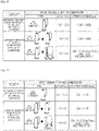
- the washing machine, and the refresher in response to there being one laundry treating machine that requires the heated air, one compressor may be operated; and among the dryer, the washing machine, and the refresher, in response to there being two or more laundry treating machines that require the heated air, two compressors may be operated.
- one compressor In response to a temperature condition of the heated air, which is required for the cycles of the dryer, the washing machine, and the refresher, being a first value, one compressor may be operated; and in response to a temperature condition of the heated air, which is required for the cycles of the dryer, the washing machine, and the refresher, being a second value that is greater than the first value, two compressors may be operated.
- the number of compressors to be operated may vary according to a type of laundry treating machine that requires the heated air among the dryer, the washing machine, and the refresher.
- the cycle status may include one or more of a type of a cycle performed by each laundry treating machine, a type of loaded laundry, and a temperature condition.
- At least one of RPMs of the plurality of compressors when only one laundry treating machine performs a cycle, which requires air heated by the heating device among the cycles of the dryer, the washing machine, and the refresher, may be lower than the RPMs of the plurality of compressors when two or more laundry treating machines perform cycles which require the air heated by the heating device.
- the operated compressors may be turned off at different times.
- a cooler may be disposed in a passage between the heating device and the refresher, and the cooler may be operated when the heated air is simultaneously supplied to the refresher and the other laundry treating machines.
- the heating device may further include: an evaporator for dehumidifying air by heat exchange between introduced air and a low-temperature refrigerant; a condenser for heating air by heat exchange between a high-temperature refrigerant and air; and a fan for blowing the air heated by passing through the condenser.
- the heating device may further include a switching device for controlling a direction of the air blown by the fan.
- the laundry treating apparatus may further include flow control valves respectively disposed in a passage between the heating device and the dryer, a passage between the heating device and the washing machine, and a passage between the heating device and the refresher, wherein an opening degree of the flow control valves may be changed based on a temperature condition during cycles of laundry treating machines connected to the passages in which the flow control valves are disposed.
- the flow control valve disposed in a passage supplied with the heated air may be opened to a maximum degree.
- the heating device When only one of the plurality of compressors is operated, and the air heated by the heating device is supplied to two or more laundry treating machines among the dryer, the washing machine, and the refresher, the heating device may be operated based on a laundry treating machine that requires highest temperature air, and the flow control valve disposed in a passage connected to a laundry treating machine that requires air of a lower temperature than the highest temperature may be opened to a minimum degree.
- the opening degree of the flow control valve which is opened to the minimum degree, may gradually increase.
- the heating device may operate one or two compressors based on a temperature condition of the laundry treating machine supplied with the heated air, wherein the flow control valve disposed in a passage connected to the laundry treating machine supplied with the heated air may be opened in response to the temperature condition.
- the heating device may operate one or two compressors based on a highest temperature condition among temperature conditions of the laundry treating machines supplied with the heated air, wherein the flow control valve disposed in a passage connected to a laundry treating machine under a lower temperature condition than the highest temperature condition may be opened to a minimum degree, and then an opening degree of the flow control valve may gradually increase.
- a laundry treating apparatus including a plurality of laundry treating machines.
- a laundry treating apparatus including a washing machine, a dryer, and a refresher.
- a laundry treating apparatus in which the washing machine, the dryer, and the refresher are disposed in the same space, thereby performing washing, drying, and refreshing in the same space.
- a laundry treating apparatus in which laundry may be treated in the same space regardless of the type of laundry.
- a laundry treating apparatus in which when washing, drying, and refreshing are performed, a user's load (e.g., amount of work, workflow, etc.) for moving the laundry may be reduced.
- a user's load e.g., amount of work, workflow, etc.
- a laundry treating apparatus in which the refresher may treat laundry which may not be subjected to high temperature drying in the same space where washing and drying are performed.
- a laundry treating apparatus in which the washing machine and the refresher share one surface, thereby reducing vibrations generated in the washing machine.
- hot air may be supplied to each of the washing machine, the dryer, and the refresher by using a single heating device.
- steam may be supplied to each of the washing machine, the dryer, and the refresher by using a single steam generator.
- a laundry treating apparatus capable of minimizing the effect of a cycle status of any one laundry treating machine on another laundry treating machine.
- a laundry treating apparatus including a heating device that is operated based on a cycle status of at least one laundry treating machine.
- a laundry treating apparatus capable of supplying hot air suitable for operating conditions and loads of the respective laundry treating machines.
- a laundry treating apparatus capable of efficiently generating and supplying hot air.
- a laundry treating apparatus capable of performing operation optimized for the operating conditions and loads of the respective laundry treating machines.
- the laundry treating apparatus A may include one or more laundry treating machines.
- the laundry treating machines refer to devices for washing, drying, and/or refreshing objects (e.g., clothes, towels, bedding, etc.).
- the laundry treating apparatus A may include a plurality of laundry treating machines of the same type.
- the laundry treating apparatus A may include two or more dryers 1.
- the laundry treating apparatus A may include two or more washing machines 2.
- the laundry treating apparatus A may include two or more refreshers 3.
- the laundry treating apparatus A may include different types of laundry treating machines.
- the laundry treating apparatus may include the dryer 1, the washing machine 2, and the refresher 3.
- the laundry treating apparatus A may include a plurality of the same type of laundry treating machines and laundry treating machines which are of different types.
- the laundry treating apparatus A may include two or more washing machines, one dryer, and one refresher.
- the laundry treating apparatus A may include one washing machine, one dryer, and two or more refreshers.
- the laundry treating apparatus A of the present disclosure is not limited to the type and number of the laundry treating machines and may include various combinations thereof.
- the following description will be given of an example in which the laundry treating apparatus A includes one dryer 1, one washing machine 2, and one refresher 3, but the present disclosure is not limited thereto.
- the dryer 1, the washing machine 2, and the refresher 3 may be referred to as any one of first to third laundry treating machines, respectively.
- the dryer 1 may be referred to as the "first laundry treating machine”
- the washing machine 2 may be referred to as the “second laundry treating machine”
- the refresher 3 may be referred to as the "third laundry treating machine.
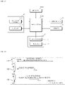
- the laundry treating apparatus A may include a controller 81 (see FIG. 2 ) for controlling operation of a dryer 1, a washing machine 2, a refresher 3, and a heating device 50.
- the controller 81 may be mounted on a Printed Circuit Board (PCB).
- the controller 81 may control the dryer 1, the washing machine 2, the refresher 3, and the heating device 50 based on an electrical signal received from a control panel 8 which will be described below.
- the controller 81 may communicate with the control panel 8.
- the dryer 1 and the washing machine 2 may be vertically disposed.
- the control panel 8 may be disposed between the dryer 1 and the washing machine 2.
- the control panel 8 and the refresher 3 may be vertically disposed.
- a user may input a command to the laundry treating apparatus A through the control panel 8.
- the user may control the operations of the dryer 1, the washing machine 2, and the refresher 3.
- the control panel 8 may transmit an electrical signal, input by the user's operation, to the controller 81.
- a space for providing the PCB may be formed in the control panel 8.
- a controller may be mounted on the PCB.
- the controller may be the controller 81.
- the controller may be disposed on a rear surface of the control panel 8.
- the space for providing the PCB may be formed on the rear surface of the control panel 8.
- the controller 81 may be mounted on the PCB.
- At least some of the washing machine 2, the dryer 1, the refresher 3, and a machine room S may include respective controllers for controlling each operation thereof. Even in this case, the respective controllers may be mounted on the PCB. The respective controllers may communicate with each other. In some cases, at least one controller may be an upper level controller that may control other controllers and devices.
- the control panel 8 may display an operating state of the laundry treating apparatus A.
- the user may check information on the operating state of the laundry treating apparatus A through the control panel 8.
- the laundry treating apparatus A may include the heating device 50.
- the heating device 50 may supply hot air to the dryer 1.
- the heating device 50 may supply hot air to the refresher 3.
- the heating device 50 may supply hot air to the washing machine 2.
- the hot air, supplied to the respective laundry treating machines, may be drawn into the heating device 50 again for circulation.
- the laundry treating apparatus of the present disclosure may discharge the hot air to the outside. That is, the laundry treating apparatus of the present disclosure may discharge the hot air supplied to a tub 23 of the washing machine 2 to the outside of the washing machine 2, may discharge the hot air supplied to a first drum 13 of the dryer 1 to the outside of the dryer 1, and may discharge the hot air supplied to an inner space 33 of the refresher 3 to the outside of the refresher 3.
- the laundry treating apparatus A may include the machine room S (see FIG. 2 ).
- the machine room S may provide a space in which the heating device 50 is disposed.
- the machine room S may be a concept that refers to a space in which the heating device 50 and components other than the heating device 50 are disposed.
- a pump, a blower fan, an air passage, a steam device, a steam passage, a dehumidification device, a controller, a motor, a fan housing, etc., in addition to the heating device 50, may be disposed in the machine room S.
- the machine room S may provide the space in which the aforementioned movable elements (a pump, a blower fan, an air passage, a steam device, a steam passage, a dehumidification device, a controller, a motor, and a fan housing) are disposed.
- the aforementioned movable elements a pump, a blower fan, an air passage, a steam device, a steam passage, a dehumidification device, a controller, a motor, and a fan housing
- the machine room S may refer to the space in which the heating device 50 is disposed or may be an upper concept that encompasses the heating device 50.
- the machine room S may include a separate case.
- the machine room S may be separated from a first cabinet 10 and a second cabinet 20.
- the machine room S may be disposed in any one of first to third cabinets 10, 20, and 30.
- the machine room S may be a concept that refers to a space in which various components including the heating device 50 are disposed. That is, in the case where the machine room S is disposed in any one of the first to third cabinets 10, 20, and 30, the machine room S may refer to a portion of the inner space of the first to third cabinets 10, 20, and 30.
- the machine room S may be vertically disposed with respect to the washing machine 2 and the dryer 1.
- the machine room S may be disposed over the washing machine 2 and the dryer 1.
- the machine room S may be disposed between the washing machine 2 and the dryer 1.
- the machine room S may be disposed under the washing machine 2 and the dryer 1.
- the machine room S and the refresher 3 may be vertically disposed.
- the machine room S may be disposed over or under of the refresher 3.
- the heating device 50 may supply hot air to the washing machine 2.
- the heating device 50 may recover the hot air supplied to the washing machine 2.
- the heating device 50 may supply hot air to the dryer 1.
- the heating device 50 may recover the hot air supplied to the dryer 1.
- the heating device 50 may supply hot air to the refresher 3.
- the heating device 50 may recover the hot air supplied to the refresher 3.
- the heating device 50 may supply steam to the washing machine 2.
- the heating device 50 may supply steam to the dryer 1.
- the heating device 50 may supply steam to the refresher 3.
- the heating device 50 may include a heat pump device.
- the heat pump device may include a compressor 51, a condenser 52, an evaporator 53, and an expansion device 54 (see FIG. 5 ).
- the heating device 50 may include a fan 60 (see FIG. 5 ).
- the heat pump device may be referred to as a "heat exchange unit.”
- the heating device 50 may include a heat exchange unit for heating air flowing through a heat exchange channel 42 (see FIG. 5 ).
- the heat exchange unit may be a heat pump device connected by a refrigerant passage.
- the heat exchange unit may be a heater that operates using electricity as power.
- the heat exchange unit may be a heating device.
- the heat exchange unit may include the heater and a cooler.
- the cooler may be disposed on an upstream side of the heater.
- the cooler may be disposed in the heat exchange channel 42.
- the cooler may dehumidify and cool air passing through the heat exchange channel 42.
- the heating device 50 may be vertically disposed with respect to the washing machine 2 and the dryer 1.
- the heating device 50 may be disposed over the washing machine 2 and the dryer 1, may be disposed between the washing machine 2 and the dryer 1, or may be disposed under the washing machine 2 and the dryer 1.
- the heating device 50 and the refresher 3 may be vertically disposed.
- the heating device 50 may be disposed in a rear space of the refresher 3.
- the heating device 50 may be disposed in the first cabinet 10.
- the heating device 50 may also be disposed in the second cabinet 20.
- the heating device 50 may also be disposed in the third cabinet 30.
- the washing machine 2, the dryer 1, and the heating device 50 may be vertically arranged, and the refresher 3 may be disposed on a lateral side of the washing machine 2 and the dryer 1.
- the heating device 50 may be disposed on a lateral side of the refresher 3.
- the dryer 1 is disposed over the washing machine 2, and the heating device 50 is disposed between the washing machine 2 and the dryer 1.
- a vertical arrangement of the washing machine 2, the dryer 1, and the heating device 50 is not limited thereto.
- the refresher 3 may be disposed on a lateral side of the washing machine 2 and the dryer 1.
- the refresher 3 may be disposed on the right side of the washing machine 2 and the dryer 1.
- an arrangement position of the refresher 3 is not limited to the above example, and the refresher 3 may be disposed on the left side of the washing machine 2 and the dryer 1.
- a longitudinal width of the refresher 3 may be smaller than a longitudinal width of the washing machine 2 and the dryer 1.
- a rear case 310 in which a hot air passage or a steam passage which will be described later is disposed, may be disposed at a rear side of the refresher 3.
- the washing machine 2 may include a second cabinet 20 having a second laundry loading opening 22 (see FIG. 2 ) formed on a front surface thereof, and a second door 21 rotatably coupled to the second cabinet 20.
- a user may open the second laundry loading opening 22 and may put the laundry into a second drum 24 through the second laundry loading opening 22.
- the dryer 1 may include the first cabinet 10 having a first laundry loading opening 12 (see FIG. 2 ) formed on a front surface thereof, and a first door 11 rotatably coupled to the first cabinet 10.
- the user may open the first laundry loading opening 12 and may put the laundry into the first drum 13 through the first laundry loading opening 12.
- the refresher 3 forms a space in which the laundry is placed, and includes a third cabinet 30 having a third laundry loading opening 32 (see FIG. 3 ) and a third door 31 rotatably coupled to the third cabinet 30.
- the third laundry loading opening 32 may be referred to as an "opening.”
- the user may open the third laundry loading opening 32 and may load the laundry into the third cabinet 30 through the third laundry loading opening 32.
- Each of the first cabinet 10, the second cabinet 20, and the third cabinet 30 may include an upper panel, a lower panel, a front panel, a rear panel, and side panels.
- the first cabinet 10 may include a first upper panel 103, a first lower panel 104, a first front panel 101, a first rear panel 102, and first side panels 105 and 106.
- the second cabinet 20 may include a second upper panel 203, a second lower panel 204, a second front panel 201, a second rear panel 202, and second side panels 205 and 206.
- the third cabinet 30 may include a third upper panel 303, a third lower panel 304, a third front panel 301, a third rear panel 302, and third side panels 305 and 306.
- the third cabinet 30 may include the third door 31 instead of the third front panel 301.
- a plate may be disposed in a space between the washing machine 2 and the refresher 3 and in a space between the dryer 1 and the refresher 3.
- the plate may be a damping material.
- the dryer 1, the washing machine 2, and the refresher 3 may be coupled to each other by the plate.
- the first upper panel 103 of the dryer 1 and the third upper panel 303 of the refresher 3 may be disposed on the same horizontal plane.
- the third upper panel 303 of the refresher 3 and an upper wall 313 of the rear case 310 may be disposed on the same horizontal plane.
- the third side panel 305 of the refresher 3 and the side wall 315 of the rear case 310 may be disposed on the same plane.
- the front panel 201 of the washing machine 2, the front panel 101 of the dryer 1, and the control panel 8 may be disposed on the same plane.
- the third door 31 of the refresher 3 may be disposed on the same plane as the front panel 201 of the washing machine 2, the front panel 101 of the dryer 1, and the control panel 8. Alternatively, the third door 31 of the refresher 3 may be disposed on the same plane as the second door 21 of the washing machine 2 and the first door 11 of the dryer 1.
- the second lower panel 204 of the washing machine 2 and the third lower panel 304 of the refresher 3 may be disposed on the same horizontal plane.
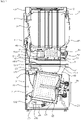
- FIG. 2 is a diagram illustrating an internal structure of the dryer 1, the washing machine 2, and the heating device 50 which are cut in a longitudinal direction.
- the washing machine 2 includes the second cabinet 20, the second door 21 rotatably coupled to the second cabinet 20, the tub 23 disposed in the second cabinet 20, a second drum 24, which is rotatably disposed in the tub 23 and in which laundry is received, a motor 25 for transmitting power to the second drum 24, a drain pump 26 for discharging water, generated in the laundry treating apparatus A, to the outside, a water supply valve 27 connected to an external water source, and a drawer 28 in which detergent is stored.
- the drain pump 26 may be connected to the tub 23 by a first pipe 261.
- the drain pump 26 may discharge water, introduced through the first pipe 261 and a drain pipe 532, to the outside of the laundry treating apparatus A through a second pipe 262.
- the water supply valve 27 may open and close water supply lines 278 and 279 (see FIG. 11 ) connecting the external water source and the washing machine 2.
- the water supply valve 27 may control a flow rate of water flowing into the washing machine 2 from the external water source.
- the water supply valve 27 may be connected to a first water supply pipe 271.
- the first water supply pipe 271 may be connected to the drawer 28 in which the detergent is stored. The water flowing into the drawer 28 through the first water supply pipe 271 may flow into the tub 23 along with the detergent in the drawer 28 through a second water supply pipe 272.
- the dryer 1 includes the first cabinet 10, the first door 11 rotatably coupled to the first cabinet 10, and the first drum 13 which is rotatably mounted in the first cabinet 10 and in which the laundry is received.
- the dryer 1 may include a motor 133 (see FIG. 5 ) for rotating the first drum 13.
- a pulley may be fixed to a rotating shaft of the motor 133.
- a belt may connect the pully with a circumferential surface of the drum 13, such that torque of the motor 133 may be transferred to the drum 13 via the pulley and the belt.
- the motor 133 may be disposed under the first drum 13.
- the motor 133 may be disposed in the heating device 50.
- the motor 133 may be disposed on a lateral side of the heat exchange channel 42.
- a motor mounting portion 133s (see FIG. 6 ) may be provided in a case 570 (see FIG. 5 ) of the heating device 50.
- the motor 133 may be directly coupled to the first drum 13 to rotate the first drum 13.
- the heating device 50 may be disposed over the second upper panel 203.
- the heating device 50 may be disposed in the first cabinet 10.
- the heating device 50 includes: a condenser 52 for performing heat exchange between a high-temperature refrigerant and air to heat the air; a fan 60 for blowing air heated by passing through the condenser 52; and an evaporator 53 for performing heat exchange between the air flowing into the heating device 50 and a low-temperature refrigerant to cool and dehumidify the air.
- the condenser 52 and the evaporator 53 may be referred to as a "heat exchange unit.”
- the air heated by passing through the condenser 52 may be blown by the fan 60, and may be supplied to at least one of the washing machine 2, the dryer 1, or the refresher 3.
- the heating device 50 may be connected to the first drum 13 by a first supply air duct 43.
- the hot air generated by the heating device 50 may be blown by the fan 60 to be supplied into the first drum 13 through the first supply air duct 43.
- the first supply air duct 43 may extend upwardly from the heating device 50.
- the heating device 50 may be connected to the tub 23 by a third supply air duct 48.
- the hot air generated by the heating device 50 may be blown by the fan 60 to be supplied into the tub 23 through the third supply air duct 48.
- the third supply air duct 48 may extend downwardly from the heating device 50.
- the hot air generated by the heating device 50 may be blown by the fan 60 to be supplied to the outside of the laundry treating apparatus A through a dehumidification duct 46.
- the dehumidification duct 46 may be disposed between a base plate 575 to be described below and the second upper panel 203.
- the air blown by the fan 60 may be supplied into an indoor space through the dehumidification duct 46.
- An opening member 463 may be disposed at a front side of the dehumidification duct 46.
- the opening member 463 may open and close the front side of the dehumidification duct 46.
- the opening member 463 may be rotatably coupled to the first cabinet 10 or the second cabinet 20.
- the supply air ducts 43, 45, and 48 may be referred to as any one of first to third supply air ducts.
- the supply air duct connected to the dryer 1 may be referred to as a first supply air duct 43;
- the supply air duct connected to the refresher 3 may be referred to as a second supply air duct 45, and the supply air duct connected to the washing machine 2 may be referred to as a third supply air duct 48.
- the supply air ducts 43, 45, and 48 may be referred to as "supply ducts.”
- the respective first, second, and third supply air ducts 43, 45, and 48 may be referred to as any one of the "first to third supply ducts.”
- the first supply air duct 43 may be referred to as a first supply duct
- the second supply air duct 45 may be referred to as a second supply duct
- the third supply air duct 48 may be referred to as a third supply duct.
- the supply air ducts 43, 45, and 48 may be referred to as "supply pipes.”
- the respective first, second, and third supply air ducts 43, 45, and 48 may be referred to as any one of the "first to third supply pipes.”
- the first supply air duct 43 may be referred to as a first supply pipe
- the second supply air duct 45 may be referred to as a second supply pipe
- the third supply air duct 48 may be referred to as a third supply pipe.
- the air supplied to the washing machine 2, the dryer 1, or the refresher 3 may be recovered to the heating device 50.
- the heating device 50 may be connected to the first drum 13 by a first exhaust air duct 41.
- the hot air flowing into the first drum 13 through the first supply air duct 43 may dry the laundry placed in the first drum 13, and then may return to the heating device 50 through the first exhaust air duct 41.
- the first exhaust air duct 41 may extend downwardly from the first drum 13.
- the heating device 50 may be connected to the tub 23 by a third exhaust air duct 47.
- the hot air flowing into the tub 23 through the third supply air duct 48 may dry the laundry placed in the second drum 24, and then may return to the heating device 50 through the third exhaust air duct 47.
- the third exhaust air duct 47 may extend upwardly from the tub 23.
- the exhaust air ducts 41, 44, and 47 may be referred to as any one of first to third exhaust air ducts.
- the exhaust air duct connected to the dryer 1 may be referred to as a first exhaust air duct 41;
- the exhaust air ducts 41, 44, and 47 may be referred to as “discharge ducts” or “return ducts.”
- the respective first, second, and third exhaust air ducts 41, 44, and 47 may be referred to as any one of "first to third discharge ducts.”
- the first exhaust air duct 41 may be referred to as a first discharge duct
- the second exhaust air duct 44 may be referred to as a second discharge duct
- a third exhaust air duct 47 may be referred to as a third discharge duct.
- the respective first, second, and third exhaust air ducts 41, 44, and 47 may be referred to as any one of "first to third return ducts.”
- first exhaust air duct 41 may be referred to as a first return duct
- second exhaust air duct 44 may be referred to as a second return duct
- third exhaust air duct 47 may be referred to as a third return duct.
- first, second, and third exhaust air ducts 41, 44, and 47 may be referred to as any one of "first to third return lines.”
- first exhaust air duct 41 may be referred to as a first return line
- second exhaust air duct 47 may be referred to as a second return line
- third exhaust air duct 44 may be referred to as a third return line.
- the hot air generated by the heating device 50 may be supplied to the washing machine 2, the dryer 1, and the refresher 3 (which may also hereinafter be referred to as devices, laundry treating devices, or laundry treating machines) to dry the laundry placed in the respective laundry treating machines 1, 2, and 3, and then may return to the heating device 50. That is, the hot air generated in the heating device 50 may circulate within the laundry treating apparatus A.
- the hot air, returning to the heating device 50 after drying the laundry placed in each of the laundry treating machines 1, 2, and 3, may contain a greater amount of moisture than the air for drying the laundry placed in one laundry treating machine.
- the evaporator 53 may reduce the temperature of the returning air and removes moisture contained in the air.
- the air returning to the heating device 50 may be heat exchanged with the evaporator 53 to generate condensate.
- the heating device 50 may include a drain pan 531 disposed under the evaporator 53.
- the drain pan 532 may receive the condensate generated in the evaporator 53.
- the drain pan 531 may be connected to the drain pump 26 by the drain pipe 532.
- the drain pipe 532 may extend downwardly from the drain pan 531 to be connected to the drain pump 26.
- the condensate collected in the drain pan 531 may flow to the drain pump 26 through the drain pipe 532, and may be discharged to the outside of the laundry treating apparatus A by the drain pump 26.
- FIG. 3 is a diagram illustrating an internal structure of the refresher 3 of the laundry treating apparatus A which is cut in a longitudinal direction.
- the refresher 3 may include the third cabinet 30 having an inner space for receiving laundry.
- the refresher 3 may include a hanger 36, on which clothing is hung, and an inner panel 34 defining a lower portion of a space 33 in which clothing is placed.
- the hanger 36 may be disposed between the third upper panel 303 and the third lower panel 304, and may be disposed closer to the third upper panel 303 than the third lower panel 304.
- the inner panel 34 may be disposed between the third upper panel 303 and the third lower panel 304, and may be disposed closer to the third lower panel 304 than the third upper panel 303.
- Garments G placed in the inner space 33 of the third cabinet 30 may be located between the hanger 36 and the inner panel 34.
- the height H of the inner space 33 may refer to a height between the hanger 36 and the inner panel 34.
- the height H of the inner space 33 may be extended compared to a case where the heating device 50 is disposed between the inner panel 34 and the third lower panel 304. Accordingly, unlike an existing refresher, the refresher 3 of the present disclosure may receive garments G having a great vertical height, such as long coats or suits.
- the refresher 3 of the present disclosure may have a longitudinal width which may be extended according to the longitudinal width of the washing machine 2 and the dryer 1. Accordingly, the refresher 3 of the present disclosure may receive a larger number of garments in the front-rear direction than the existing refresher.
- the longitudinal width W of the refresher 3 may refer to a width between the third door 31 and the third rear panel 302.
- a storage space 35 may be formed between the inner panel 34 and the third lower panel 304. Relatively small clothing items, such as socks, underwear, hats, scarves, gloves, etc., may be placed in the storage space 35.
- the inner panel 34 may be connected to the second supply air duct 45.
- the third cabinet 30 may be connected to the second exhaust air duct 44.
- the inner panel 34 may include a first inner panel 341 spaced from an upper side of the third lower panel 304, and a second inner panel 342 extending diagonally upwardly from the first inner panel 341.
- the second inner panel 342 may extend diagonally upwardly from the first inner panel 341 toward the third rear panel 302.
- the second supply air duct 45 may be connected to the second inner panel 342.
- the second inner panel 342 may have a supply air hole 343 that is open toward the inner space 33.
- the second supply air duct 45 may be connected to the supply air hole 343.
- the hot air supplied from the heating device 50 may be discharged into the inner space 33 through the supply air hole 343.
- the second supply air duct 45 may include a first hot air duct 451 disposed at a rear side of the third rear panel 302, and a second hot air duct 453 disposed at a front side of the third rear panel 302.
- the first hot air duct 451 may be disposed in the rear case 310.
- a second hot air duct 452 may be disposed in the storage space 35.
- the first hot air duct 451 and the second hot air duct 452 may be coupled to the third rear panel 302.
- the first hot air duct 451 may extend upwardly in the rear case 310 to be connected to the heating device 50.
- the second hot air duct 452 may extend upwardly to be connected to the second inner panel 342.
- the second exhaust air duct 44 may be connected to the third rear panel 302.
- the third rear panel 302 may have an exhaust air hole 302a that is open toward the inner space 33.
- the second exhaust air duct 44 may be coupled to the third rear panel 302 so as to correspond to the exhaust air hole 302a.
- the hot air discharged into the inner space 33 of the refresher 3 may dry the garments G, and then may flow into the second exhaust air duct 44 through the exhaust air hole 302a.
- the second exhaust air duct 44 may pass through the third rear panel 302 to extend into the rear case 310. After passing through the third rear panel 302, the second exhaust air duct 44 may extend downwardly in the rear case 310 to be connected to the heating device 50.
- the refresher 3 may include rollers 39 and legs 39a protruding downwardly from the third lower panel 304.
- a plurality of rollers 39 may be disposed which are spaced apart from each other in the front-rear direction.
- a roller structure of the refresher 3 may also be applied to the second lower panel 204 of the washing machine 2. The rollers of the washing machine 2 and the refresher 3 may serve to support the weight of the laundry treating apparatus A when the laundry treating apparatus A is moved.
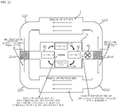
- FIG. 4 a left side of a reference line Y shows a duct system of the dryer 1 and the washing machine 2, and a right side of the reference line Y shows a duct system of the refresher 3.
- the left side of the reference line Y in FIG. 4 is a conceptual view illustrating a duct system in which the dryer 1 and the washing machine 2 are cut by a plane perpendicular to a left and right direction; and the right side of the reference line Y in FIG. 4 is a conceptual view of a rear surface of the refresher 3 to show the duct system.
- the directions used in the description of FIG. 4 may be the same as those illustrated in FIG. 1 .
- the left side of the reference line Y in FIG. 4 may be referred to as a first conceptual view S1.
- the right side of the reference line Y in FIG. 4 may be referred to as a second conceptual view S2.
- the "duct system” may be a concept that collectively refers to passages of hot air circulating in the laundry treating apparatus A.
- the "duct system” may be a concept that collectively refers to passages connecting the heating device 50, the dryer 1, the washing machine 2, and the refresher 3.
- the "duct system” may be a concept that collectively refers to passages of air heated by the heating device 50.
- the heating device 50 heats air and supplies the heated air to each of the dryer 1, the washing machine 2, and the refresher 3.
- the duct system may include the heat exchange channel 42 in which the air is heated.
- the duct system may include the first supply air duct 43 connecting the heating device 50 and the dryer 1.
- the duct system may include the second supply air duct 45 connecting the heating device 50 and the refresher 3.
- the duct system may include the third supply air duct 48 connecting the heating device 50 and the washing machine 2.
- the duct system may include the dehumidification duct 46 connected to the heating device 50.
- the air heated by passing through the heat exchange channel 42 is blown by the fan 60 to be supplied to at least any one of the first supply air duct 43, the second supply air duct 45, the third supply air duct 48, and the dehumidification duct 46.
- the duct system may include the first exhaust air duct 41 connecting the heating device 50 and the dryer 1.
- the duct system may include the second exhaust air duct 44 connecting the heating device 50 and the refresher 3.
- the duct system may include the third exhaust air duct 47 connecting the heating device 50 and the washing machine 2.
- the heated air supplied to the dryer 1 may flow into the heat exchange channel 42 through the first exhaust air duct 41.
- the heated air supplied to the refresher 3 may flow into the heat exchange channel 42 through the second exhaust air duct 44.
- the heated air supplied to the washing machine 2 may flow into the heat exchange channel 42 through the third exhaust air duct 47.
- the heat exchange channel 42 through which the air flows, may be provided in the heating device 50.
- the heating device 50 may include a heat exchange unit disposed in the heat exchange channel 42.
- the heat exchange unit may heat the air flowing in the heat exchange channel 42.
- the heat exchange unit may include the condenser 52 and the evaporator 53.
- the laundry treating apparatus A may include the fan 60.
- the fan 60 may blow the air in the heat exchange channel 42.
- the fan 60 may be disposed on a downstream side of the condenser 52.
- the air, heated by heat exchange with the evaporator 53 and the condenser 52, may be blown by the fan 60.
- the fan 60 may be disposed in the heat exchange channel 42.
- the air blown by the fan 60 may be supplied to at least any one of the dryer 1, the washing machine 2, the refresher 3, and the dehumidification duct 46.
- the laundry treating apparatus A may include a blowing duct 420 surrounding the fan 60.
- the duct system may include the blowing duct 420.
- the fan 60 may be disposed in the blowing duct 420.
- An inner space of the blowing duct 420 may be a portion of the heat exchange channel 42.
- the fan 60 and the blowing duct 420 may be disposed at a discharge end 42B of the heat exchange channel 42.
- the discharge end 42B may be disposed at a downstream side of the condenser 52 and the evaporator 53.
- the blowing duct 420 may include a first discharge port 425 connected to the first supply air duct 43.
- the blowing duct 420 may include a second discharge port 427 connected to the second supply air duct 45.
- the blowing duct 420 may include a third discharge port 426 connected to the third supply air duct 48.
- the blowing duct 420 may include a fourth discharge port 428 connected to the dehumidification duct 46.
- the first discharge port 425 may protrude upwardly from the blowing duct 420.
- the first supply air duct 43 may connect the first drum 13 and the first discharge port 425.
- the second discharge port 427 may protrude from the blowing duct 420 to a lateral side.
- the second supply air duct 45 may connect the third cabinet 30 and the second discharge port 427.
- the third discharge port 426 may protrude downwardly from the blowing duct 420.
- the third supply air duct 48 may connect the tub 23 and the third discharge port 426.
- the fourth discharge port 428 may protrude from the blowing duct 420 to the lateral side.
- the fourth discharge port 428 may protrude in a direction opposite to the second discharge port 427.
- the dehumidification duct 46 may be connected to the fourth discharge port 428.
- a rotating body 71 of a switching device 70 (see FIG. 6 ) which will be described later may be disposed in the blowing duct 420.
- the rotating body 71 may be connected to a driving motor 711 to be rotated in the blowing duct 420.
- the air blown by the fan 60 may flow into at least any one of the first supply air duct 43, the second supply air duct 45, the third supply air duct 48, and the dehumidification duct 46 by the operation of the switching device 70.
- the laundry treating apparatus A of the present disclosure may also include a separate distribution device in addition to the switching device 70 which will be described later.
- the distribution device may distribute the air blown by the fan 60 to each of the dryer 1, the washing machine 2, the refresher 3, and the dehumidification duct 46.
- the air blown by the fan 60 may be supplied at the same time to each of the dryer 1, the washing machine 2, the refresher 3, and the dehumidification duct 46.
- the distribution device may be disposed in the blowing duct 420 or may be disposed in a distribution passage connected to the blowing duct 420.
- the distribution device may be a valve.
- the distribution device may include an actuator and a switching damper.
- the laundry treating apparatus A may include both the switching device 70 and the distribution device at the same time, may include only the switching device 70, or may include only the distribution device.
- the hot air flowing into the first drum 13 through the first supply air duct 43 may dry the laundry placed in the first drum 13, and then may flow into the heat exchange channel 42 through the first exhaust air duct 41.
- the first drum 13 may include a front cover 131 disposed on a front side, and a rear cover 132 disposed on a rear side.
- the first supply air duct 43 may be connected to the rear cover 132, and the first exhaust air duct 41 may be connected to the front cover 131.
- the first exhaust air duct 41 may connect the first drum 13 and the heat exchange channel 42.
- the first exhaust air duct 41 may extend downwardly from the first drum 13 to be connected to the heat exchange channel 42.
- a first inlet port 421 connected to the first exhaust air duct 41 may be formed at an inlet end 42A of the heat exchange channel 42.
- the first inlet port 421 may extend upwardly from the heat exchange channel 42.
- the first inlet port 421 may extend upwardly from the case 570 of the heating device 50.
- the laundry treating apparatus A may include a first opening and closing valve 41a disposed in the first exhaust air duct 41.
- the first opening and closing valve 41a may control a flow rate of air in the first exhaust air duct 41.
- the first opening and closing valve 41a may block an air flow in the first exhaust air duct 41.
- the first opening and closing valve 41a may block the air flow in the first exhaust air duct 41 when the hot air is not supplied into the first drum 13 through the first supply air duct 43.
- the hot air flowing into third cabinet 30 through the second supply air duct 45 may dry the laundry placed in the third cabinet 30, and then may flow into the heat exchange channel 42 through the second exhaust air duct 44.
- the second supply air duct 45 and the second exhaust air duct 44 may be connected to the third rear panel 302 of the third cabinet 30.
- the second exhaust air duct 44 may connect the third cabinet 30 and the heat exchange channel 42.
- the second exhaust air duct 44 may extend downwardly from an upper portion of the third cabinet 30 to be connected to the heat exchange channel 42.
- the second exhaust air duct 44 may include a first duct section 444 disposed between the heating device 50 and the second cabinet 20.
- a first duct section 444 may be disposed between a base plate 575 (see FIG. 10 ) to be described later and the second upper panel 203 of the second cabinet 20.
- the first duct section 444 may extend forwardly and rearwardly in a separation space 55 (see FIG. 10 ) which will be described later.
- a second inlet port 422 connected to the second exhaust air duct 44 may be formed at the inlet end 42A of the heat exchange channel 42.
- the second inlet port 422 may extend downwardly from the heat exchange channel 42.
- the second inlet port 422 may extend downwardly from the case 570 of the heating device 50.
- the laundry treating apparatus A may include a second opening and closing valve 44a disposed in the second exhaust air duct 44.
- the second opening and closing valve 44a may control a flow rate of air in the second exhaust air duct 44.
- the second opening and closing valve 44a may block an air flow in the second exhaust air duct 44.
- the second opening and closing valve 44a may block the air flow in the second exhaust air duct 44 when the hot air is not supplied into the third cabinet 30 through the second supply air duct 45.
- the second opening and closing valve 44a may be disposed in the first duct section 444.
- the hot air flowing into the tub 23 through the third supply air duct 48 may dry the laundry placed in the tub 23, and then may flow into the heat exchange channel 42 through the third exhaust air duct 47.
- the third exhaust air duct 47 may connect the tub 23 and the heat exchange channel 42.
- the third exhaust air duct 47 may extend upwardly from an upper portion of the tub 23 to be connected to the heat exchange channel 42.
- a third inlet port 424 connected to the third exhaust air duct 47 may be formed at the inlet end 42A of the heat exchange channel 42.
- the third inlet port 424 may extend downwardly from the heat exchange channel 42.
- the third inlet port 424 may extend downwardly from the second exhaust air duct 44.
- the third inlet port 424 may extend downwardly from the first duct section 444.
- the third inlet port 424 may protrude downwardly from a lower surface of the second exhaust air duct 44.
- the third exhaust air duct 47 may connect the tub 23 and the third inlet port 424.
- the third exhaust air duct 47 may connect the tub 23 and the second exhaust air duct 44.
- the air in the third exhaust air duct 47 may join the air in the second exhaust air duct 44 to flow into the heat exchange channel 42.
- the laundry treating apparatus A may include a third opening and closing valve 47a disposed in the third exhaust air duct 47.
- the third opening and closing valve 47a may control a flow rate of air in the third exhaust air duct 47.
- the third opening and closing valve 47a may block an air flow in the third exhaust air duct 47.
- the third opening and closing valve 47a may block the air flow in the third exhaust air duct 47 when the hot air is not supplied into the tub 23 through the third supply air duct 48.
- the hot air flowing through the dehumidification duct 46 may be supplied to the outside of the laundry treating apparatus A through an outlet 462 that is open forward.
- the hot air flowing through the dehumidification duct 46 may be supplied into an indoor space through the outlet 462.
- the dehumidification duct 46 may include a second duct section 461 disposed between the heating device 50 and the second cabinet 20.
- the second duct section 461 may be disposed between the base plate 575 (see FIG. 10 ) to be described later and the second upper panel 203 of the second cabinet 20.
- the second duct section 461 may extend forwardly and rearwardly in the separation space 55 (see FIG. 6 ) which will be described later.
- An outside air inlet port 423 connected to the heat exchange channel 42 may be formed at the inlet end 42A of the heat exchange channel 42.
- the outside air inlet port 423 may extend forwardly from the heat exchange channel 42.
- the outside air inlet port 423 may extend forwardly from the second exhaust air duct 44.
- the outside air inlet port 423 may protrude forwardly from one side of the second exhaust air duct 44.
- the outside air inlet port 423 may allow the indoor space and the second exhaust air duct 44 to communicate with each other.
- the air in the outside air inlet port 423 may join the air in the second exhaust air duct 44 to flow into the heat exchange channel 42.
- the outside air inlet port 423 may have an outside air inlet 49 that is opened forward. The air drawn in through the outside air inlet 49 may join the air in the second exhaust air duct 44 to flow into the heat exchange channel 42.
- the laundry treating apparatus A may include a fourth opening and closing valve 49a disposed at the outside air inlet port 423.
- the fourth opening and closing valve 49a may control a flow rate of air in the outside air inlet port 423.
- the fourth opening and closing valve 49a may block an air flow in the outside air inlet port 423.
- the fourth opening and closing valve 49a may block the air flow in the outside air inlet port 423 when the hot air is not supplied to the dehumidification duct 46.
- FIGS. 5 and 6 are top-side perspective views of the heating device 50
- FIG. 7 is a bottom-side perspective view of the heating device 50.
- the heating device 50 may include the compressor 51 for compressing a refrigerant and heat exchangers 52 and 53 for heat exchange between the refrigerant and air.
- the compressor 51 When the compressor 51 operates, the refrigerant is compressed such that the temperature of the refrigerant increases.
- the refrigerant discharged from the compressor 51 may be heat exchanged with air via the condenser 52 and the evaporator 53.
- the evaporator 53 may be provided on an upstream side along a flow direction of air
- the condenser 52 may be provided on a downstream side of the evaporator 53, such that the introduced air is first heat exchanged with the evaporator 53, thereby removing or reducing humidity in the air.
- the air After being heat exchanged with the evaporator 53, the air is heat exchanged with the condenser 52, such that the air may be changed into relatively high temperature dry air.
- a high temperature and high pressure refrigerant, compressed by the compressor 51, is heat exchanged with ambient air in the condenser 52, is decompressed and expanded by passing through the expansion device 53, and then may absorb latent heat around the evaporator 53 and is evaporated therein.
- the heating device 50 may include the case 570, the compressor 51, the condenser 52, the evaporator 53, and the expansion device 54.
- the compressor 51, the condenser 52, the evaporator 53, and the expansion device 54 may be connected by a refrigerant passage.
- the heat pump device may include the compressor 51, the condenser 52, the evaporator 53, and the expansion device 54.
- the drain pan 531 may be disposed under the evaporator 53.
- the case 570 may provide a space in which the compressor 51, the condenser 52, the fan 60, and the evaporator 53 are disposed.
- the compressor 51, the condenser 52, the fan 60, the evaporator 53, and the switching device 70 may be disposed in the case 570.
- the case 570 may include a cover 573, a base plate 575 spaced from a lower side of the cover 573, a front wall 574 disposed at a front side of the condenser 53, a first side wall 571 disposed on one side of the condenser 53, and a second side wall 572 disposed on the other side of the condenser 53.
- the drum motor 133 rotating the first drum 13 of the dryer 1 may be disposed in the case 570 of the heating device 50.
- the drum motor 133 may be disposed on an upper side of the case 570.
- the case 570 may provide a motor mounting portion 133s on which the drum motor 133 is mounted.
- the condenser 52, the fan 60, and the evaporator 53 may be disposed on an upper side of the base plate 575.
- the heat exchange channel 42 may be a space surrounded by the base plate 575, the front wall 574, the first side wall 571, and the second side wall 572.
- the cover 573 may not be provided, in which case an upper portion of the heat exchange channel 42 may be open.
- the heat exchange channel 42 may communicate with the fan 60 disposed at a rear portion of the heating device 50. Air in the heat exchange channel 42 may be blown by the fan 60.
- the heat exchange channel 42 may be referred to as a "heating passage.”
- the condenser 52 and the evaporator 53 may be disposed in the heat exchange channel 42.
- the heat exchange channel 42 may refer to a partially open space.
- the heat exchange channel 42 may be a space surrounded by the cover 573, the base plate 575, the front wall 574, the first side wall 571, and the second side wall 572.
- the cover 573 may cover the upper portion of the heat exchange channel 42.
- the heat exchange channel 42 may refer to a space between the cover 573 and the base plate 575.
- the cover 573, the base plate 575, the front wall 574, the first side wall 571, and the second side wall 572 may form a "heating duct" surrounding the heat exchange channel 42.
- the heating duct may communicate with the fan 60, and air in the heating duct may be blown by the fan 60.
- the condenser 52 and the evaporator 53 may be disposed in the heating duct.
- the heat exchange channel 42 may refer to a duct shielded in all directions.
- the heat exchange channel 42 may be formed in the heating device 50.
- the heat exchange channel 42 may be a portion of the inner space of the heating device 50.
- the first inlet port 421 may be disposed at a front side of the heat exchange channel 42.
- the first inlet port 421 may cover the front side of the heat exchange channel 42.
- the first inlet port 421 may be connected to the front wall 574.
- the first inlet port 421 may be formed in the case 570.
- the first exhaust air duct 41 may be inserted into the first inlet port 421 and may be fixed thereto.
- the heating device 50 may be disposed in the machine room S.
- the controller 81 may control the operation of components disposed in the machine room S.
- the machine room S may have a space in which the PCB is disposed, and the controller 81 may be mounted on the PCB.
- the heating device 50 may include a steam generator 502 for generating steam and a dehumidifier 504 for removing moisture from the air flowing through the heat exchange channel 42.
- the steam generator 502 may generate steam by heating water.
- the steam generator 502 may be disposed between the condenser 52 and the fan 60.
- the steam generated by the steam generator 502 may be pressurized by the fan 60 to be supplied to each of the washing machine 2, the dryer 1, and the refresher 3.
- the steam generated by the steam generator 502 may be supplied to each of the first drum 13, the second drum 24, and the inner space 33 of the refresher 3.
- the dehumidifier 504 may dehumidify air under room temperature conditions (about 25 degrees Celsius).
- the dehumidifier 504 may dehumidify air by using desiccant cooling.
- the dehumidifier 504 may be filled with zeolite.
- the zeolite filled in the dehumidifier 504 may be replaced periodically.
- the dehumidifier 504 may be disposed between the condenser 52 and the fan 60.
- the dehumidifier 504 may dehumidify the air flowing through the heat exchange channel 42 even when the compressor 51 is not in operation.
- the switching device 70 may control the direction of air blown by the fan 60.
- the switching device 70 may be disposed in the machine room S.
- the switching device 70 may control the supply of hot air to the washing machine 2, the dryer 1, the refresher 3, or the dehumidification duct 46.
- the switching device 70 may include the rotating body 71 rotatably mounted in the blowing duct 70.
- the switching device 70 may include the driving motor 711 that rotates the rotating body 71.
- the rotating body 71 may be rotated by the driving motor 711 in the blowing duct 420.
- the fan 60 may be disposed in the rotating body 71.
- the driving motor 711 may rotate the rotating body 711.
- a driving gear 712 may be fixed to the rotating shaft of the driving motor 711.
- the driving gear 712 may be a pinion gear or a spur gear.
- a driven gear 713 may be rotated in engagement with the driving gear 712.
- the driven gear 713 may be fixed to the rotating body 71 or may be integrally formed with the rotating body 71.
- the driven gear 713 may be a ring gear.
- the driven gear 713 may be a ring-shaped rack.
- the driving gear 712 and the driven gear 713 may be engaged with each other.
- the driven gear 713 may be moved in a circumferential direction with respect to the rotational axis of the fan 60.
- the rotating body 71 having the driven gear 713 fixed thereto may also be moved in the circumferential direction with respect to the rotational axis of the fan 60.
- the driving motor 712 may be disposed outside of the blowing duct 420.
- One surface (e.g., rear surface) of the blowing duct 420 that faces the rotating body 71 may have a cut-out portion 714.
- the cut-out portion 714 may be formed at a position corresponding to the driven gear 713.
- a portion of the driving gear 712 may be inserted into the cut-out portion 714.
- the driving gear 712 and the driven gear 713 may be engaged with each other in the cut-out portion 714.
- a rotating shaft of the driving motor 711 may be disposed side by side with the rear surface of the blowing duct 420. Accordingly, a volume occupied by the driving motor 711 and the driving gear 712 in the front-rear direction may be reduced.
- the driving motor 711 may be a motor capable of controlling the position, angle, and direction of rotation.
- the driving motor may be a Brushless Direct Current (BLDC) motor.
- the driving motor 711 may be a step motor.
- the driving motor 711 may be electrically connected to the control panel 8 and/or the controller 81. Rotation of the driving motor 711 may be controlled by an electrical signal transmitted from the control panel 8 and/or the controller 81 to the driving motor 711.
- the control panel 8 and/or the controller 81 may control a hot air supplying direction by controlling the rotation angle of the driving motor 711.
- the driving motor 711 may rotate the rotating body 71 by various known methods used by the motor for rotating the rotating body.
- the driving motor 711 may rotate the rotating body 71 by using a belt-pulley method, or by using a plurality of gears that are engaged with each other, or the rotating shaft of the motor may be rotated together with the rotating body.
- the blowing duct 420 may be connected to the first supply air duct 43, the second supply air duct 45, the third supply air duct 48, and the dehumidification duct 46.
- the blowing duct 420 may be connected to a motor mount 64, to which a fan motor rotating the fan 60 is fixed.
- the motor mount 64 may be disposed on a rear surface of the blowing duct 420.
- the driving motor 711, the driving gear 712, and the driven gear 713 may be disposed radially outwardly from the motor mount 64.
- the blowing duct 420 may include the first discharge port 425, the second discharge port 427, the third discharge port 426, and the fourth discharge port 428.
- the first supply air duct 43 may be connected to the first discharge port 425.
- the first supply air duct 43 may be inserted into the first discharge port 425.
- the first discharge port 425 may be directed upward in the blowing duct 420.
- the first discharge port 425 may provide a supply air hole that is vertically open.
- the second supply air duct 45 may be connected to the second discharge port 427.
- the second supply air duct 45 may be inserted into the second discharge port 427.
- the second discharge port 427 may be directed toward the lateral side in the blowing duct 420.
- the second discharge port 427 may provide a supply air hole that is horizontally open.
- the third supply air duct 48 may be connected to the third discharge port 426.
- the third supply air duct 48 may be inserted into the third discharge port 426.
- the third discharge port 426 may be directed downward in the blowing duct 420.
- the third discharge port 426 may provide a supply air hole that is vertically open.
- the dehumidification duct 46 may be connected to the fourth discharge port 428.
- the dehumidification duct 46 may be inserted into the fourth discharge port 428.
- the fourth discharge port 428 may be directed toward a direction opposite to the second discharge port 427.
- the fourth discharge port 428 may be directed toward the lateral side in the blowing duct 420.
- the fourth discharge port 428 may provide a supply air hole that is horizontally open.
- the heating device 50 may be connected to each of the first exhaust air duct 41, the second exhaust air duct 44, the third exhaust air duct 47, and the outside air inlet port 423.
- the third exhaust air duct 47 and the outside air inlet port 423 may be connected to the heating device 50 via the second exhaust air duct 44.
- the heating device 50 may include the first inlet port 421 connected to the first exhaust air duct 41, and the second inlet port 422 connected to the second exhaust air duct 44.
- the first inlet port 421 may extend upwardly, and the second inlet port 422 may extend downwardly.
- the first inlet port 421 and the second inlet port 422 may protrude from the case 570 of the heating device 50.
- Air drawn into the heating device 50 through the first exhaust air duct 41, the second exhaust air duct 44, the third exhaust air duct 47, and the outside air inlet port 423 may pass through the heat exchange channel 42 and flow into the fan 60 by the suction force of the fan 60.
- the air flowing through the first exhaust air duct 41, the second exhaust air duct 44, the third exhaust air duct 47, and the outside air inlet port 423 may meet in the heat exchange channel 42 to flow into the fan 60.
- the third inlet port 424 connected to the third exhaust air duct 47 may protrude downwardly from the second exhaust air duct 44.
- the air in the third exhaust air duct 47 may join the air in the second exhaust air duct 44 to flow into the heat exchange channel 42.
- the outside air inlet port 423 communicating with the indoor space may protrude forwardly from the second exhaust air duct 44.
- the air flowing into the outside air inlet port 423 through the outside air inlet 49 may join the air in the second exhaust air duct 44 to flow into the heat exchange channel 42.
- the air flowing into the heat exchange channel 42 through the second exhaust air duct 44 may join the air flowing into the heat exchange channel 42 through the first exhaust air duct 41 to flow to the fan 60.
- the heating device 50 may include a first support plate 576 extending downwardly from the base plate 575, and a second support plate 577 extending downwardly from the base plate 575 and spaced apart from the first support plate 576.
- a separation space 55 may be formed between the first support plate 576 and the second support plate 577.
- the second exhaust air duct 44, the third exhaust air duct 48, and the dehumidification duct 46 may be disposed in the separation space 55.
- the second exhaust air duct 44, the third exhaust air duct 48, and the dehumidification duct 46 may be formed between the first support plate 576 and the second support plate 577.
- the second exhaust air duct 44, the third exhaust air duct 48, and the dehumidification duct 46 may be disposed under the base plate 575.
- the dehumidification duct 42 may be disposed under the base plate 575 and may extend forwardly to discharge the air forwardly through a hot air outlet 462.
- a hot air outlet 462 When an opening member 463 (see FIG. 10 ) which will be described later opens a front side of the separation space 55, the air discharged through the hot air outlet 462 may be discharged forwardly from the laundry treating apparatus A.
- a portion of the second exhaust air duct 44 disposed under the base plate 575 may be defined as the first duct section 444.
- a portion of the dehumidification duct 46 disposed under the base plate 575 may be defined as the second duct section 461.
- FIG. 8 (a) is a diagram illustrating an example of operation when air is supplied to the first supply air duct 43 by the operation of the switching device 70, and (b) is a diagram illustrating an example of operation when air is supplied to the first supply air duct 43 and the second supply air duct 45 at the same time by the operation of the switching device 70.
- the fan 60 may be a Sirocco fan.
- the fan 60 may rotate to blow air in a direction perpendicular to the rotating shaft 61.
- the fan 60 may blow air in a direction coming into contact with the rotation direction.
- the air blown by the fan 60 may be concentrated in a predetermined range of angles relative to the rotating shaft 61.
- the fan 60 may include the rotating shaft 61 coupled to the fan motor and rotated thereby, a plurality of blades 62 spaced apart in a radially outward direction of the rotating shaft 61, and an outer body 63 coupled to the blades 62 and extending in a rotation direction of the fan 60.
- the outer body 63 may have an annular shape.
- the rotating shaft 61 and the blades 62 may be connected by the outer body 63. When the rotating shaft 61 rotates, the outer body 63 and the blades 62 may also be rotated together with the rotating shaft 61.
- the rotating body 71 may include a rotating plate 71a having the driven gear 713, a scroll 71b coupled to the rotating plate 71a, and a shaft through hole 71c formed in the rotating plate 71a.
- the rotating plate 71a may have a disk shape and may be disposed at a rear side of the fan 60.
- the driven gear 713 may be formed in an annular shape on one side surface of the rotating plate 71a.
- the driven gear 713 may be formed integrally with the rotating plate 71a.
- the rotating plate 71a may have the shaft through hole 71c, through which the rotating shaft 61 passes.
- the rotating shaft 61 may pass through the shaft through hole 71c to be coupled to the fan motor.
- the fan 60 may be disposed between the heat exchange channel 24 and the rotating plate 71a. That is, the rotating plate 71a may be disposed behind the heat exchange channel 42 and the fan 60. The rotating plate 71a may be disposed behind the fan 60 in the blowing duct 420.
- the scroll 71b may be integrally formed with the rotating plate 71a. When the rotating plate 71a is rotated, the scroll 71b may also be rotated together. The scroll 71b may extend in the rotation direction of the fan 60. The scroll 71b may be disposed to surround the fan 60. The fan 60 may be disposed in the scroll 71b.
- the scroll 71b may include a blowing channel 72.
- the blowing channel 72 may be a cut-out portion of an outer circumferential surface of the scroll 71b.
- the scroll 71b may cover the outside of the fan 60, and the blowing channel 72 may be an outer region of the fan 60 which is not covered by the scroll 71b.
- the air blown by the fan 60 may be discharged to the outside of the blowing duct 420 through the blowing channel 72.
- the blowing channel 72 When the scroll 71b is rotated by the rotation of the rotating plate 71a, the blowing channel 72 may be changed in position. That is, by the rotation of the scroll 71b, the position of the blowing channel 72 may be changed relative to the rotating shaft 61. By rotating the scroll 71b to change the position of the blowing channel 72, the driving motor 711 may control the direction of air discharged from the blowing duct 420.
- a longitudinal section of the blowing duct 420 may have a square shape. Accordingly, by the rotation of the scroll 71b, interference between the scroll 71 and the blowing duct 420 may be avoided.
- the blowing duct 420 may include a first wall 420a disposed over the fan 60, a second wall 420b disposed under the fan 60, a third wall 420c disposed on one side of the fan 60, and a fourth wall 420d disposed on the other side of the fan 60.
- the first discharge port 425 may protrude upwardly from the first wall 420a.
- the second discharge port 427 may protrude toward the lateral side from the third wall 240c.
- the third discharge port 426 may protrude downwardly from the second wall 420b.
- the fourth discharge port 428 may protrude toward the lateral side from the fourth wall 420d.
- the driving motor 711 may rotate the rotating body 71 by a first angle, and when the rotating body 71 is rotated by the first angle, the air blown by the fan 60 may be supplied to the first supply air duct 43.
- the blowing channel 72 may communicate with only an inner space of the first discharge port 425. Accordingly, the air blown by the fan 60 may be supplied to only the dryer 1.
- the driving motor 711 may rotate the rotating body 71 by a second angle, and when the rotating body 71 is rotated by the second angle, the air blown by the fan 60 may be supplied to the first supply air duct 43 and the second supply air duct 45 at the same time.
- the blowing channel 72 may communicate with an inner space of the first discharge port 425 and an inner space of the second discharge port 427. Accordingly, the air blown by the fan 60 may be supplied to the dryer 1 and the refresher 3 at the same time.
- the blowing channel 72 may include a first blowing channel 72a communicating with the inner space of the first discharge port 425, and a second blowing channel 72b communicating with the inner space of the second discharge port 427.
- the air blown by the fan 60 may be supplied to the dryer 1 through the first blowing channel 72a.
- the air blown by the fan 60 may be supplied to the refresher 3 through the second blowing channel 72b.
- a user may control the switching device 70 by inputting a signal to the control panel 8.
- the signal may be transmitted to the driving motor 711, to control a rotation angle of the driving motor 711.
- the driving motor 711 may rotate the rotating body 71 so that the blowing channel 72 may be moved to a position as illustrated in (a) of FIG. 8 .
- the driving motor 711 may rotate the rotating body 71 so that the blowing channel 72 may be moved to a position as illustrated in (b) of FIG. 8 .
- FIG. 9 is an enlarged view of a portion of a rear surface of the laundry treating apparatus A.
- the heating device 50 may be disposed over the second upper panel 203.
- the heating device 50 may be disposed in the cabinet 10 of the dryer 1.
- the switching device 70 may be disposed over the second upper panel 203.
- the switching device 70 may be disposed in the cabinet 10 of the dryer 1.
- the blowing duct 420 may be connected to the first supply air duct 43, the second supply air duct 45, and the third supply air duct 48.
- the first supply air duct 43 may extend upwardly from the blowing duct 420.
- the first supply air duct 43 may be connected to the first drum 13.
- the second supply air duct 45 may extend from the blowing duct 420 to a lateral side.
- the second supply air duct 45 may be connected to the third cabinet 30.
- the third supply air duct 48 may extend downwardly from the blowing duct 420.
- the third supply air duct 48 may pass through the separation space 55 to extend into the second cabinet 20.
- the laundry treating apparatus A may include a first steam supply pipe 502a connecting the steam generator 502 and the first drum 13, a second steam supply pipe 502c connecting the steam generator 502 and the third cabinet 30, and a third steam supply pipe 502b connecting the steam generator 502 and the tub 23.
- the steam generator 502 may be disposed in the heating device 50.
- the steam generated by the steam generator 502 may be sprayed into the first drum 13 through the first steam supply pipe 502a.
- the steam generated by the steam generator 502 may be sprayed into the inner space 33 of the refresher 3 through the second steam supply pipe 502c.
- the steam generated by the steam generator 502 may be sprayed into the second drum 24 through the third steam supply pipe 502b.
- the first steam supply pipe 502a may extend upwardly from the steam generator 502 to be connected to the first drum 13.
- the second steam supply pipe 502c may extend from the steam generator 502 to the lateral side, to be connected to the third cabinet 30.
- the third steam supply pipe 502b may extend downwardly from the steam generator 502 to be connected to the tub 23.
- the steam generated by the steam generator 502 may flow to each of the first drum 13, the second drum 24, and the inner space 33 of the refresher 3 by the blowing force of the fan 60. That is, by pressurizing the steam generated by the steam generator 502, the fan 60 may cause the steam to flow into the first drum 13, the second drum 24, and the inner space 33 of the refresher 3.
- a valve for controlling an amount of steam flow may be provided for each of the first steam supply pipe 502a, the second steam supply pipe 502c, and the third steam supply pipe 502b.
- the controller 81 may adjust the amount of steam supplied to each of the first drum 13, the second drum 24, and the inner space 33 of the refresher 3.
- the washing machine 2 may be connected to a cold water supply pipe 278 for supplying cold water to the tub 23, and a hot water supply pipe 279 for supplying hot water to the tub 23.
- the steam generator 502 may be connected to a third water supply pipe 277 branching off from the cold water supply pipe 278 or the hot water supply pipe 279.
- the steam generator 502 may be connected to the third water supply pipe 277 branching off from the hot water supply pipe 279.
- the steam generator 502 may be supplied with hot water through the third water supply pipe 277.
- the steam generator 502 may generate steam by heating the water supplied through the third water supply pipe 277.
- Water supply ports 273 and 274 may be disposed closer to the second upper panel 203 than to the second lower panel 204.
- the steam generator 502 may be disposed between the second upper panel 203 and the first drum 13. Accordingly, as a distance between the steam generator 502 and the water supply pipes 278 and 279 becomes shorter, the third water supply pipe 277 may be reduced in length.
- FIG. 10 is a diagram illustrating a state in which the first cabinet 10 and the second cabinet 20 are separated from each other.
- the base plate 575 of the heating device 50 may be spaced from the upper side of the second upper panel 203 of the washing machine 2.
- the separation space 55 may be formed between the base plate 575 and the second upper panel 203.
- the first side panels 105 and 106 of the dryer 1 may protrude downwardly below the base plate 575.
- the first side walls 105 and 106 may include a 1-1 side panel 105 forming one side surface of the laundry treating apparatus A, and a 1-2 side panel 106 facing the third cabinet 30.
- the heating device 50 may include the first support plate 576 extending downwardly from the base plate 575.
- the first support plate 576 may be disposed inside the 1-1 side panel 105.
- the heating device 50 may include the second support plate 577 extending downwardly from the base plate 575.
- the second support plate 577 may be disposed inside the 1-2 side panel 106.
- the base plate 575 and the support plates 576 and 577 may be integrally formed with each other.
- the 1-1 side panel 105 and the first support plate 576 may be integrally formed with each other.
- the 1-2 side panel 106 and the second support plate 577 may be integrally formed with each other.
- the first side panels 105 and 106 may include first protrusions 105a and 106a protruding downwardly.
- the 1-1 side panel 105 may include a 1-1 protrusion 105a protruding downwardly.
- the 1-2 side panel 106 may include a 1-2 protrusion 106a protruding downwardly.
- the first protrusions 105a and 106a may protrude downwardly from a lower end of the first side panels 105 and 106.
- the second cabinet 20 may include first recesses 203a into which the first protrusions 105a and 106a are inserted.
- the first recesses 203a may be formed in the second upper panel 203.
- the first recesses 203a may be formed at positions corresponding to the first protrusions 105a and 106a.
- the support plates 276 and 277 may include second protrusions 576a and 577a protruding downwardly.
- the first support plate 276 may include a 2-1 protrusion 576a protruding downwardly.
- the second support plate 577 may include a 2-2 protrusion 577a protruding downwardly.
- the second protrusions 576a and 577a may protrude downwardly from a lower end of the support plates 576 and 577.
- the second cabinet 20 may include second recesses 203b into which the second protrusions 576a and 577a are inserted.
- the second recesses 203b may be formed in the second upper panel 203.
- the second recesses 203b may be formed at positions corresponding to the second protrusions 576a and 577a.
- the first protrusions 105a and 106b and the second protrusions 576a and 577a may be referred to as “protrusions.”
- the first recesses 203a and the second recesses 203b may be referred to as "recesses.”
- the first cabinet 10 and the second cabinet 20 may be coupled to each other by the protrusions 105a, 106b, 576a, and 577a inserted into the recesses 203a and 203b.
- the machine room S may be disposed over the base plate 575. Accordingly, the machine room S may be spaced from the upper side of the second upper panel 203.
- the separation space 55 may be formed between the first support plate 576 and the second support plate 577.
- the second exhaust air duct 44, the dehumidification duct 46, and the third exhaust air duct 48 may be disposed in the separation space 55.
- the second exhaust air duct 44, the dehumidification duct 46, and the third supply air duct 48 may be disposed between the second upper panel 203 and the base plate 575.
- the third supply air duct 48 may protrude downwardly toward the second upper panel 203.
- the third supply air duct 48 may include a first connection duct 48a extending downwardly from the blowing duct 230, and a second connection duct 48b connected to the tub 23.
- the first connection duct 48a may be disposed in the separation space 55.
- the second connection duct 48b may extend downwardly from the second upper panel 203 to be connected to the tub 23.
- the second connection duct 48b may have a first insertion hole 48s which is formed on the inside thereof, and into which the first connection duct 48a is inserted.
- the first connection duct 48a is inserted into the first insertion hole 48s to be fixed to the second connection duct 48b.
- the third inlet port 424 may be connected to the second exhaust air duct 44 and may be disposed in the separation space 55.
- the third inlet port 424 may be inserted into a second insertion hole 47s, formed on the inside of the third exhaust air duct 47, to be fixed to the third exhaust air duct 47.
- the first connection duct 48a and the third inlet port 424 are inserted into the first insertion hole 48s and the second insertion hole 47s, respectively, to be fixed thereto, thereby facilitating the assembly and alignment of the first cabinet 10 and the second cabinet 20.
- the laundry treating apparatus A may include an auxiliary panel 58 disposed at a rear side of the separation space 55.
- the auxiliary panel 58 may shield a rear side of the separation space 55.
- the auxiliary panel 58 may be connected to the first rear panel 102 and the second rear panel 202.
- the first rear panel 102 and the second rear panel 202 may be connected to each other by the auxiliary panel 58.
- the auxiliary panel 58 may include a duct through hole 59, through which the second exhaust air duct 44 passes.
- the second exhaust air duct 44 may pass through the auxiliary panel 58 to extend into the separation space 55.
- the auxiliary panel 58 may be coupled to the first side panels 105 and 106 and the support plates 576 and 577.
- the opening member 463 may shield the front side of the separation space 55.
- the opening member 463 may be disposed at the front side of the dehumidification duct 46 and the outside air inlet port 423.
- the laundry treating apparatus A may include a hinge 463a connected to the opening member 463, and a motor 463b rotating the hinge 463a.
- the hinge 463a may be rotatably connected to the first front panel 101.
- the hinge 463a may extend in a left-right direction.
- the opening member 463 may be rotated in a front-rear direction with respect to the hinge 463a serving as a rotational axis.
- the opening member 463 may be integrally formed with the hinge 463a.
- the motor 463b rotates the hinge 463a
- the opening member 463 may be rotated together with the hinge 463a.
- the opening member 463 may be rotated forward to open the front side of the separation space 55.
- outside air of the laundry treating apparatus A may flow into the heat exchange channel 44 through the outside air inlet port 423, and the air passing through the dehumidification duct 46 may be discharged to the outside of the laundry treating apparatus A.
- the controller 81 may be electrically connected to the motor 463b.
- the controller 81 may control the operation of the motor 463b.
- the user may open the separation space 55 by operating the control panel 8.
- FIG. 11 is a rear view of the laundry treating apparatus A, from which the rear case 310 is removed.
- the second supply air duct 45 and the second exhaust air duct 44 for circulating hot air to the refresher 3 may be disposed at the rear side of the third cabinet 30.
- the second supply air duct 45 and the second exhaust air duct 44 may be disposed behind the third rear panel 302.
- the second supply air duct 45 may extend downwardly from the heating device 50 to be connected to the inner panel 34.
- the second supply air duct 45 may face the second side panel 206 of the washing machine 2.
- the second supply air duct 45 may be disposed side by side with the second side panel 206.
- the second supply air duct 45 may include the first hot air duct 451 and the second hot air duct 452.
- the first hot air duct 451 may include a first connection part 451a connected to the heating device 50, a first extension part 451b extending downwardly from the first connection part 451a, and a second connection part 451c connected to the second hot air duct 452.
- the first connection part 451a may be coupled to the first side panel 106 of the first cabinet 10.
- the first connection part 451a may be connected to the blowing duct 420, and the air blown by the fan 60 may be introduced through the first connection part 451a.
- the first connection part 451a may extend horizontally from the heating device 50.
- the first extension part 451b may be bent downwardly from the first connection part 451a.
- the first extension part 451b may extend downwardly from one end of the first connection part 451a.
- the first extension part 451b may face the second side panel 206 of the washing machine 2 and may be disposed side by side with the second side panel 206.
- the second connection part 451c may be coupled to the third rear panel 302 of the third cabinet 30.
- the second connection part 451c may be coupled to the second hot air duct 452. That is, the third rear panel 302 may be disposed between the second hot air duct 452 and the second connection part 451c.
- the second connection part 451c may extend from the first extension part 451b in the front-rear direction.
- the washing machine 2 may include water supply ports 273 and 274 connected to the external water source.
- the water supply ports 273 and 274 may be connected to the water supply pipes 278 and 279 which are connected to the external water source.
- the tub 23 may be supplied with water from the external water source through the water supply pipes 278 and 279.
- the water supply ports 273 and 274 may include a first water supply port 273 connected to the cold water supply pipe 278 for supplying cold water, and a second water supply port 274 connected to the hot water supply pipe 279 for supplying hot water.
- the tub 23 may be supplied with cold water through the cold water supply pipe 278, and may be supplied with hot water through the hot water supply pipe 279.
- the water supply valve 270 may be connected to the cold water supply pipe 278 and the hot water supply pipe 279, and may control an amount of cold water and hot water flowing into the tub 23.
- the laundry treating apparatus A may include a cooling pipe 275 branching off from the cold water supply pipe 289 or the hot water supply pipe 279.
- the cooling pipe 275 may branch off from the cold water supply pipe 278.
- the cooling pipe 275 may branch off from the cold water supply pipe 278 to be disposed adjacent to the second supply air duct 45.
- the cooling pipe 275 may extend side by side with the second supply air duct 45 or may come into contact with the second supply air duct 45.
- Hot air flowing in the second supply air duct 45 may be heat exchanged with water flowing in the cooling pipe 275, such that temperature of the hot air may be reduced.
- the cooling pipe 275 may be disposed adjacent to the first extension part 451b or may come into contact with the first extension part 451b.
- the cooling pipe 275 may be connected to the drain pump 26. Water branched off from the cold water supply pipe 278 and flowing into the cooling pipe 275 may be heat exchanged with the hot air flowing in the second supply air duct 45, and then may flow into the drain pump 26. The drain pump 26 may discharge the water, introduced through the cooling pipe 275, to the outside of the laundry treating apparatus A.
- Clothing treated by the refresher 3 may be susceptible to damage when dried at a high temperature. It is required to supply hot air at a relatively lower temperature to the clothing dried by the refresher 3 than clothing treated by the dryer 1 and the washing machine 2. High temperature hot air generated by the heating device 50 may be supplied directly to the washing machine 2 or the dryer 1. However, the high temperature hot air generated by the heating device 50 is required to be cooled before being supplied to the refresher 3. Accordingly, in the laundry treating apparatus A according to the present disclosure, hot air at a lower temperature than the hot air supplied to the washing machine 2 and the dryer 1 may be supplied to the refresher 3 by using the water supply pipes 275, 278, and 279 of the washing machine 2, thereby preventing damage to the clothing placed in the refresher 3. In addition, by discharging water, used for reducing the temperature of the hot air supplied to the refresher 3, to the outside through the drain pump 26, it is possible to effectively manage the water used for cooling the hot air.
- the second exhaust air duct 44 may include a third connection part 441 connected to the third cabinet 30, a second extension part 442 extending downwardly from the third connection part 441, and a fourth connection part 443 connected to the heating device 50.
- the third connection part 441 may be coupled to the third rear panel 302 of the third cabinet 30.
- the third connection part 441 may communicate with the inner space 33 of the refresher 3, and air circulating in the refresher 3 may flow through the third connection part 441.
- the third connection part 441 may extend rearwardly from the third cabinet 30. A position where the third connection part 441 and the third cabinet 30 are connected may be between the third upper panel 303 and the hanger 36.
- the second extension part 442 may be bent downwardly from the third connection part 441.
- the second extension part 442 may extend downwardly from the third connection part 441.
- the second extension part 442 may extend downwardly from one end of the third connection part 441.
- the second connection part 442 may face the first side panel 106 of the dryer 1 and may be disposed side by side with the first side panel 106.
- the fourth connection part 443 may extend into the separation space 55.
- the fourth connection part 443 may extend in the front-rear direction from the second extension part 442.
- the fourth connection part 443 may be connected to the heating device 50 in the separation device 55.
- FIGS. 12 to 14 a laundry treating apparatus B according to an embodiment of the present disclosure will be described with reference to FIGS. 12 to 14 .
- the dryer 1 is disposed under the washing machine 2, and the heating device 50 is disposed under the dryer 1.
- the laundry treating apparatus B illustrated in FIGS. 12 to 14 is different from the laundry treating apparatus A described above with reference to FIGS. 1 to 11 in terms of arrangement of the washing machine 2, the dryer 1, and the heating device 50.
- components other than those related to the arrangement of the washing machine 2, the dryer 1, and the heating device 50, may be the same as the components of the laundry treating apparatus A described above with reference to FIGS. 1 to 11 .
- the heating device 50 may be disposed in the dryer 1.
- the heating device 50 may be disposed in the first cabinet 10.
- the heating device 50 may be disposed at a lower portion of the first cabinet 10 or under the first drum 13 (see FIG. 13 ).
- the second upper panel 203 of the washing machine 2 and the third upper panel 303 of the refresher 3 may be disposed on the same horizontal plane.
- the third upper panel 303 of the refresher 3 and the upper wall 313 of the rear case 310 may be disposed on the same horizontal plane.
- the first lower panel 104 of the dryer 1 and the third lower panel 304 of the refresher 3 may be disposed on the same horizontal plane.
- the drain pump 26 may be connected to the tub 23 by a first pipe 261.
- the drain pump 26 may discharge water, introduced through the first pipe 261, to the outside of the laundry treating apparatus B through a second pipe 262.
- the heating device 50 may be disposed under the second cabinet 320.
- the heating device 50 may be disposed in the first cabinet 10.
- the heating device 50 may be disposed under the first drum 13.
- the third supply air duct 48 may be connected to an upper portion of the tub 23.
- the dehumidification duct 46 may be disposed between the base plate 575 and the first lower panel 104.
- the opening member 463 may be rotatably coupled to the first cabinet 10.
- the third exhaust air duct 47 may be connected to the upper portion of the tub 23.
- the drain pan 531 may discharge condensate to the outside of the laundry treating apparatus B through the drain pipe 532.
- the drain pipe 532 may be connected to the drain pump 26.
- a separate transfer pump for extruding the condensate collected in the drain pan 531 may be provided in the machine room S.
- the third supply air duct 48 may branch off from the second supply air duct 45, and a third discharge port 426 may be formed at a portion where the third supply air duct 48 branches off from the second supply air duct 45.
- the third discharge port 426 may protrude upwardly from the second supply air duct 45.
- the third supply air duct 48 may connect the tub 23 and the third discharge port 426.
- the third supply air duct 48 may connect the tub 23 and the second supply air duct 45.
- the second supply air duct 45 may be connected to the third rear panel 302 of the third cabinet 30.
- the second exhaust air duct 44 may pass through the third side panel 306 of the third cabinet 30 to be connected to the heat exchange channel 42.
- the second exhaust air duct 44 may connect the third cabinet 30 and the heat exchange channel 42.
- the second exhaust air duct 44 may extend downwardly in a lateral direction from the upper and lower sides of the third cabinet 30, to be connected to the heat exchange channel 42.
- the second inlet port 422 connected to the second exhaust air duct 44 may be formed at the inlet end 42A of the heat exchange channel 42.
- the second inlet port 422 may extend from the heat exchange channel 42 to the lateral side.
- the second inlet port 422 may extend from the third exhaust air duct 47 to the lateral side.
- the second inlet port 422 may extend from a first duct section 471 to the lateral side.
- the second inlet port 422 may protrude from one side surface of the third exhaust air duct 47 to the lateral side.
- the second exhaust air duct 44 may connect the inner space 33 of the refresher 3 and the second inlet port 422.
- the second exhaust air duct 44 may connect the inner space 33 of the refresher 3 and the third exhaust air duct 47.
- the air in the second exhaust air duct 44 may join the air in the third exhaust air duct 47, to flow into the heat exchange channel 42.
- the third exhaust air duct 47 may extend from the upper side of the tub 23, to be connected to the heat exchange channel 42.
- the third exhaust air duct 47 may include the first duct section 471 located between the base plate 575 and the first lower panel 104.
- the first duct section 471 may be disposed in the separation space 55.
- the first duct section 471 may extend forwardly and rearwardly in the separation space 55.
- the third inlet port 424 connected to the third exhaust air duct 47 may be formed at the inlet end 42A of the heat exchange channel 42.
- the third inlet port 424 may extend downwardly from the heat exchange channel 42.
- the third inlet port 424 may extend downwardly from the case 570 of the heating device 50.
- the dehumidification duct 46 may include a second duct section 461 disposed between the base plate 575 and the first lower panel 104.
- the second duct section 461 may be disposed in the separation space 55.
- the second duct section 461 may extend forwardly and rearwardly in the separation space 55.
- the outside air inlet port 423 may extend forwardly from the third exhaust air duct 47.
- the outside air inlet port 423 may protrude forwardly from one side of the third exhaust air duct 47.
- the outside air inlet port 423 may allow the inner space and the third exhaust air duct 47 to communicate with each other.
- the air in the outside air inlet port 423 may join the air in the third exhaust air duct 47 to flow into the heat exchange channel 42.
- the outside air inlet port 423 may have the outside air inlet 49 that is open forward. The air drawn in through the outside air inlet 49 may join the air in the third exhaust air duct 47 to flow into the heat exchange channel 42.
- FIG. 15 is an internal block diagram schematically illustrating a laundry treating apparatus according to an embodiment of the present disclosure.
- At least one of the devices 1, 2, 3, and 50 included in the laundry treating apparatuses A and B may include a sensor unit 1150, an interface 1160, a memory 1130, a communication module 1120, and a processor 1110 for controlling the overall operation thereof, which may be commonly included in the respective devices 1, 2, 3, and 50, and a detailed configuration thereof may vary depending on characteristics of the apparatuses.
- the respective devices 1, 2, 3, and 50 may have components for performing predetermined operations and a driver 1140 for the components.
- the washing machine 2 may include a motor 133 for transmitting power to the second rotatable drum 240, the drain pump 260 for discharging water, generated in the laundry treating apparatuses A and B, to the outside thereof, and the like.
- the driver 1140 of the washing machine 2 may include a motor driver, such as an inverter and the like, for driving the motor 250, a pump driver for driving the drain pump 260, and the like.
- the heating device 50 may include a steam generator 502 for generating steam and a dehumidifier 504 for removing moisture from the air flowing through the heat exchange channel 42.
- the steam generator 502 may be included in another component.
- the steam generator 502 may be disposed in the machine room S or in the dryer 1.
- the refresher 3 may include the hanger 36, a hanger motor for moving the hanger 36, and the like.
- the sensor unit 1150 may include a plurality of sensors for sensing a state of the laundry treating apparatuses A and B.
- the sensor unit 1150 may include various types of sensors.
- the sensor unit 1150 may include a temperature sensor, a humidity sensor, a pressure sensor, and the like.
- the sensors included in the sensor unit 1150 may be disposed at positions required for obtaining data.
- various sensors may be disposed in the heating device 6, the duct system, and the respective laundry treating machines 1, 2, and 3.
- the type, number, and installation position of sensors included in the sensor unit 1150 may vary depending on the type of the devices 1, 2, 3, and 50.
- the memory 1130 may store control data for controlling operations of the devices 1, 2, 3, and 50, and operation data generated or sensed during the operations.
- the memory 1130 may store execution programs for each function, data for controlling the operations, and transmitted and received data.
- the interface 1160 may include components for receiving a user's control command.
- the interface 1160 may include a receiver for receiving a control command transmitted from a remote control device.
- the interface 1160 may include at least one input means, such as a button, a switch, and a touch input means.
- the interface 1160 may include a control panel 1611 and/or a display 1162.
- the control panel 1611 may be the aforementioned control panel 8.
- the control panel 1611 may include a control panel disposed at another position, in addition to the control panel 8 disposed between the washing machine 2 and the dryer 1.
- the display 1162 may visually display predetermined information.
- the display 1162 may output state information of the laundry treating apparatuses A and B, data sensed by the sensors, guide information guiding a specific operation/function, and the like.
- the washing machine 2 and the dryer 1 may have front surfaces through which laundry therein may be seen, such that the display 1162 is desirably disposed on a front surface of the refresher 3. Accordingly, compared to the front surfaces of the washing machine 2 and the dryer 1, the display 1162 may be implemented as a large screen display.
- the display 1162 may be implemented as a touch screen and may be used as an input means.
- the interface 1160 may apply the input data to the processor 1110.
- the processor 1110 may control the devices 1, 2, 3, and 50.
- the processor 1110 may control the heating device 50 to heat air.
- the processor 1110 may switch a passage to supply the air, heated by the heating device 50, to at least one of the laundry treating machines 1, 2, and 3.
- processor 1110 may control the steam generator 502 and the like to supply steam to at least one of the laundry treating machines 1, 2, and 3.
- the processor 1110 may be the aforesaid controller 690.
- the processor 1110 may correspond to controllers provided for at least some of the devices 1, 2, 3, and 50.
- the washing machine 2, the dryer 1, the refresher 3, and the machine room S may include respective controllers for controlling each operation thereof.
- the controllers may be mounted on a printed circuit board (PCB) disposed in the respective devices 1, 2, 3, and 50.
- the processor 1110 may correspond to the controllers of the devices 1, 2, 3, and 50 and may control the operations of the respective devices 1, 2, 3, and 50.
- the respective controllers may communicate with each other.
- at least one controller may be an upper level controller that may control other controllers and devices.
- some of the devices 1, 2, 3, and 50 may be operated under the control of the controllers mounted on the PCB of the other devices.
- the processor 1110 may be implemented as a block of the controller, and any one controller may include a plurality of processors 1110.
- the plurality of processors 1110 may be disposed in the same predetermined space or may be mounted on a single PCB. Alternatively, some of the plurality of processors 1110 may be mounted on another PCB.
- the devices 1, 2, 3, and 50 may communicate with another device, the mobile terminal 1020, and the like through the communication module 1120.
- the communication module 1120 of at least some of the devices 1, 2, 3, and 50 may include a wireless communication module to communicate wirelessly with the mobile terminal 1020 and the like.
- at least one of the devices 1, 2, 3, and 50 may include a plurality of different types of communication modules.
- the communication module 1120 may include a transmitter 1121 for transmitting predetermined data to another device.
- the devices 1, 2, 3, and 50 may include a receiver 1122 for receiving predetermined data from another device.
- the transmitter 1121 and the receiver 1122 may be integrated as a transceiver.
- a user may execute an application or may access a predetermined website to remotely monitor and control the laundry treating apparatuses A and B.
- the user may receive various services by registering the laundry treating apparatuses A and B with a manufacturer or a service provider.
- the laundry treating apparatuses A and B includes the washing machine 2, the dryer 1 disposed vertically with respect to the washing machine 2, the refresher 3 disposed on one side of the washing machine 2 and the dryer 1, and the heating device 50 heating air supplied to at least one of the washing machine 2, the dryer 1, and the refresher 3.
- hot air may be supplied to the washing machine 2, the dryer 1, and the refresher 3 by using the common heating device 50.
- the heating device 50 may be operated based on a cycle status of at least one of the laundry treating machines 1, 2, and 3, and may heat air to supply the heated air to at least one of the washing machine 2, the dryer 1, and the refresher 3.
- the heating device 50 supplies hot air based on the cycle status of at least one of the laundry treating machines 1, 2, and 3, such that the other laundry treating machines 1, 2, and 3 may be less affected by the cycle status of one of the laundry treating machines 1, 2, and 3, thereby operating efficiently.
- the processor 1110 may control the heating device 50 to heat air and to supply the heated air (hot air) to at least one of the laundry treating machines 1, 2, and 3.
- the processor 1110 may control the supply of hot air based on the cycle status of at least one of the laundry treating machines 1, 2, and 3.
- the heating device 50 may include one compressor 51.
- the heating device 50 may include a plurality of compressors 51.
- FIGS. 16 to 21 are diagrams referred to in the description of a compressor included in the heating device according to an embodiment of the present disclosure.
- the compressor 51 is a device for compressing a refrigerant, and examples thereof include a reciprocating compressor 1610 that produces compression pressure by a rectilinear reciprocating motion of a piston, and rotary compressors 1620 and 1630 that produce compression pressure by a rotary motion of a roller, and a scroll compressor that produces compression pressure by the rotation of a scroll.
- the reciprocating compressor 1610 is used in the widest range of applications. Vibrations occur in the reciprocating compressor 1610 due to the rectilinear motion of the piston, but by fixing the reciprocating compressor 1610 to the machine room and the like using a supporting structure such as four springs and the like, the vibrations in the entire product may be reduced compared to the vibrations caused by the rotary motion.
- a dual rotary compressor 1630 having a dual eccentric portion, has an improved efficiency over the single rotary compressor 1620, and is widely used in home appliances such as a home air conditioner, a dehumidifier, a dryer, and the like.
- a single horizontal rotary compressor may also be used, which is effective in terms of use of space and price.
- the scroll compressor may be used in large-capacity devices, as well as in the home appliances.
- the heating device 50 supplies hot air to the washing machine 2, the dryer 1, and the refresher 3. Accordingly, it is required to select specifications of the compressor 51 by considering sequential operations of the washing machine 2, the dryer 1, and the refresher 3 (stepwise independent operations: washing ⁇ dehydration ⁇ drying ⁇ refreshing). Further, in consideration of the case where the washing machine 2, the dryer 1, and the refresher 3 are operated at the same time, it is required to provide the compressor 51 having a sufficient capacity.
- the heating device 50 may include the compressor 51 having a large capacity that may meet the load when the washing machine 2, the dryer 1, and the refresher 3 are operated at the same time.
- the compressor 51 having a large capacity that may meet the load when the washing machine 2, the dryer 1, and the refresher 3 are operated at the same time.
- low load conditions such as low temperature drying, drying delicate clothing items such as lingerie, drying heat-sensitive clothing items such as wool/knit, etc., it is inefficient to respond to all the drying operations with one large-capacity compressor.
- the heating device 50 includes the plurality of compressors 51 to operate with an optimal efficiency by adjusting the number of compressors 51 to be operated, an operating frequency, and the like according to load conditions. For example, when a minimum load operation is required, only one of the compressors 51 may be operated to minimize power consumption.
- At least one of the compressors 51 included in the heating device 50 may have a different capacity from the other compressors. For example, by selecting and combining two compressors having different capacities, a maximum drying load may be met, and when a minimum load operation is required, only one compressor having a minimum capacity is operated to minimize power consumption.
- the heating device 50 may include two compressors 51, and by adjusting the number (e.g., one or two) of the compressors 51 to be operated and an operating frequency thereof, the heating device 50 may control the temperature of supplied hot air, thereby efficiently supplying hot air according to fabric characteristics and providing efficient operation by considering a drying time.
- the plurality of compressors 51 included in the heating device 50 may have different compression methods. Referring to FIG. 17 , an example is illustrated in which the reciprocating compressor 1610 and the dual rotary compressor 1630 are connected in parallel with each other.
- the plurality of compressors 51 included in the heating device 50 may have different capacities and compression methods. Accordingly, the compressors 51 may be provided in various combinations.
- the heating device 50 of integrated laundry treating apparatuses A and B may include one or a plurality of compressors 51.
- the processor 1110 may control the operation of the compressors 51 for supplying hot air suitable for a cycle status of the respective laundry treating machines 1, 2, and 3.
- the processor 1110 may operate only one of the two compressors 51, which is suitable to the capacity of the load, to generate hot air and to supply the generated hot air to the laundry treating machine being in operation.
- the processor 1110 may operate two compressors 51 at the same time to generate hot air according to the capacity, and may supply the generated hot air to the laundry treating machines being in operation.
- FIG. 18 is a diagram illustrating comparison of types and specifications of compressors applied to each of an existing dryer, washing machine, and refresher.
- each of the existing dryer, washing machine, and refresher includes one type of compressor.
- the capacity of the included compressor is set to a capacity that meets the load during a cycle of each single product.
- the dryer may include the dual rotary compressor having the largest capacity of 10.2 cc and the widest operation range of 1200 rpm to 7800 rpm among the illustrated products, so as to respond to the load during the drying cycle.
- the washing machine using less hot air, generated by a heat pump, than the dryer may include a single horizontal rotary compressor, which is effective in terms of use of space and price.
- the compressor included in the washing machine may be a single horizontal rotary compressor having a capacity of 7.2 cc and an operation range of 1200 rpm to 5400 rpm.
- the refresher uses hot air and steam during a clothing refreshing process, in which hot air at a relatively lower temperature than hot air for the drying cycle of the dryer is used.
- the refresher may use a dual rotary compressor having a capacity of 9.2 cc and an operation range of 1200 rpm to 5400 rpm, or a reciprocating compressor having a capacity of 8.2 cc and an operation range of 1200 rpm to 5400 rpm.
- FIGS. 19 to 21 are diagrams illustrating examples of selecting a compressor for use in the common heating device 50 that supplies hot air and steam to the respective laundry treating machines 1, 2, and 3 in the integrated laundry treating apparatuses A and B in which the washing machine 2, the dryer 1, and the refresher 3 are integrated.
- FIG. 19 is an example of selecting specifications of the compressor in the case where the washing machine 2, the dryer 1, and the refresher 3 are sequentially operated.
- a user may operate the laundry treating apparatuses A and B in the order of washing ⁇ dehydration ⁇ drying ⁇ refreshing.
- the single operation may be performed stepwise in the order of washing machine 2, the dryer 1, and the refresher 3.
- the hot air may be supplied sequentially one after another. Even in this case, the washing machine 2, the dryer 1, and the refresher 3 may be operated independently.
- the heating device 50 may include a plurality of compressors to operate a small capacity compressor to reduce power consumption during a drying process at low operating load conditions, including low temperature drying, drying of delicate clothing items such as lingerie, drying of heat-sensitive clothing items such as wool/knit and the like.
- a combination of two compressors may be selected which have a capacity corresponding to a capacity of one individual compressor.
- a combination of the dual rotary compressor having a capacity of 6.6 cc and an operation range of 1200 rpm to 5400 rpm and the reciprocating compressor having a capacity of 4.0 cc and an operation range of 1200 rpm to 4500 rpm may be provided, thereby meeting a maximum drying load, and when a minimum load operation is required, only one compressor having a minimum capacity may be operated to minimize power consumption.
- FIG. 20 is a diagram illustrating an example of selecting specifications of a compressor by considering an integrated operation in which the washing machine 2 and the dryer 1 are operated at the same time, an integrated operation in which the dryer 1 and the refresher 3 are operated at the same time, and an integrated operation in which the washing machine 2 and the refresher 3 are operated at the same time.
- one dual rotary compressor is applied which has a capacity of 18 cc to 20.0 cc corresponding to combined capacities of the existing individual products.
- a total of two compressors may be combined in which one compressor is added in consideration of an operating capacity combined with a small capacity compressor for reducing power consumption.
- a 10.2 cc dual rotary compressor and a 9.2 cc dual rotary compressor may be combined, or the 10.2 cc dual rotary compressor and an 8.2 cc dual rotary compressor may be combined, thereby meeting a maximum drying load, and during a minimum load operation, only one small capacity compressor may be operated to minimize power consumption.
- FIG. 21 is a diagram illustrating an example of selecting specifications of a compressor in consideration of an integrated operation in which three units of the washing machine 2, the dryer 1, and the refresher 3 are operated at the same time.
- one dual rotary compressor is applied which has a capacity of 25 cc to 27 cc corresponding to combined capacities of the existing individual products.
- a total of two compressors may be combined, including a small capacity compressor for reducing power consumption, and one compressor which is added in consideration of an operating capacity during the integrated operation of all the units, thereby meeting a maximum drying load, and during a minimum load operation, only one small capacity compressor may be operated to minimize power consumption.
- a 17.4 cc dual rotary compressor and a 9.2 cc dual rotary compressor may be combined, or the17.4 cc dual rotary compressor and the 8.2 cc reciprocating compressor may be combined.
- the heating device 50 may include a plurality of compressors.
- a total capacity of the plurality of compressors may be greater than a sum of loads of heated air which is required for cycles of the dryer 1, the washing machine 2, and the refresher 3.
- a capacity of a compressor having a minimum capacity may be greater than a minimum load value among the loads of the heated air, which is required for cycles of the dryer 1, the washing machine 2, and the refresher 3.
- the processor 1110 may control the number of compressors 51 to be operated, according to a cycle status of the dryer 1, the washing machine, and the refresher 3.
- the processor 1110 may also control an RPM of the compressors 51 to be operated, according to a cycle status of the dryer 1, the washing machine, and the refresher 3.
- hot air may be supplied in consideration of the temperature of hot air (high temperature/medium temperature/low temperature) according to the cycles of the respective machines.
- hot air may be supplied differently according to a cycle status of the respective machines.
- hot air having a high temperature may be supplied to the dryer 1, and at the same time hot air having a relatively medium temperature or low temperature may be supplied to the refresher 3.
- the processor 1110 may control operation by differentiating the temperature hot air supplied to the refresher 3 from the temperature hot air supplied to the dryer 1/washing machine 2 according to cycles and operation characteristics of the respective machines.
- the number (one or two) of the operated compressors 51 and an operating RPM thereof may be controlled according to a cycle/load condition, thereby minimizing the effect of a cycle of one unit on the supply of hot air to another unit.
- hot air may be supplied efficiently according to fabric characteristics, and efficient operation may be provided by considering a drying time.
- the processor 1110 may vary the number of the compressors 51 to be operated, according to a cycle status of one or more units.
- the cycle status may include one or more of the following: the type of cycles performed by the respective laundry treating machines, the type of loaded laundry, and a temperature condition.
- the processor 1110 may operate one compressor. If a temperature condition of the heated air, which is required for the cycles of the dryer 1, the washing machine 2, and the refresher 3, is a second value, which is greater than the first value, the processor 1110 may operate two compressors.
- the number of the compressors 51 to be operated may vary according to the type of laundry treating machine that requires hot air, among the dryer 1, the washing machine 2, and the refresher 3.
- the processor 1110 may control the number of the compressors 51 to be operated and the operating RPM (speed of revolution) of the respective compressors 51.
- At least one of the RPMs of the plurality of compressors 51 may be lower than the RPMs of the plurality of compressors when two or more laundry treating machines perform cycles that require the air heated by the heating device 50.
- the processor 1110 may differently control the operating frequency (RPM) of the first compressor and the second compressor.
- the operating frequency of the first compressor may be higher than that of the second compressor.
- the processor 1110 may increase the operating frequency of the first compressor and the second compressor.
- the processor 1110 may decrease the operating frequency.
- the processor 1110 may decrease the operating frequency of the first and second compressors or may decrease the operating frequency of either the first compressor or the second compressor.
- the number of the compressors 51 to be operated and the operating frequency of the respective compressors may vary depending on the number of the operated units and a combination thereof.
- the processor 1110 may operate two compressors 51 at a high RPM.
- the processor 1110 may operate only one compressor 51 at a low RPM.
- the processor 1110 may operate one compressor 51, and if two laundry treating machines require the heated air among the dryer 1, the washing machine 2, and the refresher 3, the processor 1110 may operate two compressors 51.
- the processor 1110 may further operate one additional compressor. In addition, if the plurality of compressors 51 are operated, the operated compressors may be turned off at different times. The processor 1110 may operate two compressors when the plurality of units performs a drying cycle, and then when a drying cycle of one unit is finished, the processor 1110 may turn off one of the compressors.
- the temperature of the hot air supplied to the refresher 3 may be different from the temperature of the hot air supplied to the dryer 1/washing machine 2.
- the processor 1110 may adjust the temperature of the hot air. Even when all the units are operated at the same time, the processor 1110 may separately supply hot air suitable for operating conditions and loads of the respective units.
- a cooler may be disposed in a passage between the heating device 50 and the refresher 3.
- the cooler for reducing the temperature of flowing air, discharged to the refresher 3, may be disposed in the hot air passage.
- the cooler may be operated. The cooler is operated when hot air is supplied to the refresher 3 and the other laundry treating machines 1 and 2 at the same time, thereby preventing damage to clothing which is caused by high temperature hot air supplied to the refresher 3.
- flow control valves 2315 and 2325 may be further provided in a passage between the heating device 50 and the dryer 1, a passage between the heating device 50 and the washing machine 2, and the passage between the heating device 50 and the refresher 3.
- An opening degree of the flow control valves 2315 and 2325 may be changed based on temperature conditions during cycles of the laundry treating machines connected to the passages in which the flow control valves 2315 and 2325 are disposed. According to the cycle status of the laundry treating machines 1, 2, and 3, the processor 1110 may control the heating device 50 and the flow control valves 2315 and 2325.
- the flow control valves 2315 and 2325 disposed in the passages for supplying the heated air may be opened to the maximum.
- the heating device 50 When only one of the compressors 51 is operated, and the air heated by the heating device 50 is supplied to two or more laundry treating machines among the dryer 1, the washing machine 2, and the refresher 3, the heating device 50 is operated based on the laundry treating machine requiring air of the highest temperature.
- the processor 1110 may control the flow control valves 2315 and 2325, disposed in the passages connected to the laundry treating machines requiring air of a lower temperature than the highest temperature, to be opened to the minimum.
- the processor 1110 may gradually increase the opening degree of the flow control valves 2315 and 2325 which are opened to the minimum.
- the processor 1110 may first open the flow control valves to a minimum opening degree according to the low drying temperature, and then may gradually increase the opening degree thereof until a target low temperature is reached.
- the heating device 50 may operate one or two compressors 51 according to the temperature condition of the laundry treating machine supplied with the hot air.
- the flow control valves 2315 and 2325 disposed in the passages connected to the laundry treating machine supplied with the hot air, may be opened according to the temperature condition.
- the heating device 50 may operate one or two compressors 51 based on a highest temperature condition, among the temperature conditions of the laundry treating machines supplied with the hot air.
- the flow control valves 2315 and 2325 disposed in the passages connected to the laundry treating machine under a temperature condition lower than the highest temperature condition, may be opened to the minimum, and the opening degree thereof may gradually increase.
- FIG. 22 is a diagram referred to in the description of an example of supplying hot air according to an embodiment of the present disclosure, in which hot air is supplied to the dryer 1 and the refresher 3.
- the heating device 50 disposed in the machine room S may heat introduced air to generate high temperature hot air.
- the hot air generated by the heating device 50 is supplied to the washing machine 2, the dryer 1, and the refresher 3 to dry laundry placed in the respective laundry treating machines 1, 2, and 3, and then may be recovered to the heating device 50.
- the heating device 50 may include the compressor 51, the condenser 52, the evaporator 53, and the expansion device 54. In addition, the heating device 50 may further include the fan 60.
- the laundry treating apparatuses A and B may include a distribution device 2210 and/or the switching device 70 for distributing the air, blown by the fan 60, to each of the dryer 1, the washing machine 2, the refresher 3, and the dehumidification duct 46.
- the distribution device 2210 and/or the switching device 70 may be disposed in the machine room S, the passages 2221, 2222, 2231, and 2232, and the like.
- the distribution device 2210 may be a valve.
- the distribution device 2210 may include branch pipes 2310 and 2320 and the flow control valves 2315 and 2325.
- FIG. 23 is a diagram referred to in the description of an example of supplying hot air according to an embodiment of the present disclosure, in which the branch pipes 2310 and 2320 and the flow control valves 2315 and 2325 are illustrated. While FIG. 23 illustrates an example in which the flow controls valves 2315 and 2325 are disposed in a branch passage toward the washing machine 2 and the refresher 3, the present disclosure is not limited thereto.
- the flow controls valves 2315 and 2325 may also be disposed in a main passage toward the dryer 1. Particularly, the flow controls valves 2315 and 2325 may be disposed after the branch pipe 2320 for controlling a flow amount of the dryer 1.
- hot air generated by operating two compressors is supplied according to operating conditions of the respective units 1, 2, and 3.
- the processor 1110 may adjust the temperature and amount of hot air by controlling the branch pipes 2310 and 2320 and the flow control valves 2315 and 2325 installed at an inlet of a duct for supplying the hot air to the respective units 1, 2, and 3, thereby supplying hot air at an optimal temperature.
- the flow control valves 2315 and 2325 may be opened and closed to control a flow amount.
- the processor 1110 may also control a minute flow amount by controlling an opening degree of the flow control valves 2315 and 2325.
- the flow control valves 2315 and 2325 may be an Electronic Expansion Valve (EEV). By controlling a minute flow amount of hot air by controlling an opening degree from 0 to 500 steps and from 0 to 2,000 steps, the processor 1110 may supply hot air according to an optimal temperature for each product.
- EEV Electronic Expansion Valve
- high temperature humid air moisture absorbed from clothes
- low temperature dry air having passed through the evaporator 53
- the heating device 50 discharges high temperature dry air, which is heated by passing through the condenser 52, to the laundry treating machines 1, 2, and 3 operating in the drying cycle.
- the processor 1110 may control the temperature of hot air by controlling operation of the compressor 51.
- the processor 1110 may increase an amount of refrigerant by operating both of the first and second compressors at the same time or by increasing the RPM of the compressor. Accordingly, the increased amount of refrigerant (increase in heat exchange quantity) may lead to an increase in temperature of the hot air having passed through the condenser 52 and flowing toward the dryer 1 and the refresher 3.
- the heating device 50 may supply the hot air to the units, requiring the hot air, through passages branching off from the main duct.
- the processor 1110 may operate only one of the first and second compressors, and may stop the other one or may reduce the RPM of the compressor. Accordingly, the decreased amount of refrigerant (decrease in heat exchange quantity) may lead to decrease in temperature of the hot air having passed through the condenser 52 and flowing toward the dryer 1 and the refresher 3.
- the processor 1110 may change compressor control conditions according to operating conditions, such as the type of clothes, drying load, high temperature/low temperature drying, and the like.
- the processor 1110 may operate two or more compressors 51.
- the processor 1110 may operate two or more compressors 51.
- the processor 110 may operate only one compressor 51 when only one unit performs drying, when low temperature drying is performed, when drying of delicate clothing items, such as lingerie, or heat-sensitive clothing items, such as wool/knit is performed, or when it is required to perform drying with hot air at a reduced temperature.
- the processor 1110 may operate only one compressor.
- the processor 1110 may stop operating one of the two compressors being in operation.
- FIG. 24 is a diagram illustrating a method of operating a laundry treating apparatus according to an embodiment of the present disclosure, in which washing and drying processes of laundry are sequentially performed in an integrated laundry treating apparatus including only one compressor or in an integrated laundry treating apparatus including a plurality of compressors and one of the plurality of compressors being in operation.
- the washing machine 2 performs a washing cycle for washing laundry loaded therein (S2410). Upon completing the washing cycle (S2415), the washing machine 2 may perform a dehydration cycle (S2420).
- operation of the heating device 50 may be started (S2430), and even if the dryer is detected to be in use (S2435), the dryer 1 may perform a drying cycle (S2440). In some cases, the washing machine 2 or the refresher 3 may perform the drying cycle (S2450). In addition, even when the dryer 1 is used (S2435), the refresher 3 may also be used, and operation of the heating device 50 may be completed (S2445).
- the hot air supply passage may be changed rapidly according to the cycle status of the units, thereby providing efficient operation.
- the temperature of hot air in the drying cycle (S2440) of the dryer 1 and the drying cycle (S2450) of the refresher 3 may be controlled by controlling the RPM of the compressor.
- the heating device 50 may increase the RPM of the compressor to generate high temperature hot air required for the drying cycle (S2440) of the dryer 1.
- the heating device 50 may generate low temperature hot air required for the drying cycle (S2450) of the refresher 3.
- an opening degree of the flow control valve 2325 which branches off from one hot air passage duct, is opened to the maximum, thereby controlling the temperature of branched and supplied hot air by controlling the RPM of the compressor.
- the heating device 50 may generate high temperature hot air required for the drying cycle (S2440) of the dryer 1, and by controlling the opening degree of the flow control valve 2325, the heating device 50 may gradually supply the hot air to the refresher 3, thereby preventing the temperature of air supplied to the refresher 3 from increasing rapidly.
- the heating device 50 may complete the operation and may be turned off (S2455).
- FIG. 25 is a flowchart illustrating a method of operating a laundry treating apparatus according to an embodiment of the present disclosure, in which in an integrated laundry treating apparatus with one compressor being in operation, a plurality of units requires a drying function.
- the processor 1110 may check a drying load for each unit (S2510).
- the processor 1110 may operate the heating device 50 (S2530) by selecting temperature of hot air based on units requiring high temperature drying (S2515, S2520 and S2525).
- the heating device 50 is operated based on a drying cycle of one of the dryer 1 and the refresher 3, which requires a higher temperature condition (S2530).
- the heating device 50 is operated according to a corresponding temperature condition (S2530).
- the processor 1110 may block the supply of hot air to corresponding units (S2580).
- the processor 1110 may minimize an opening degree of the flow control valves 2315 and 2325 in hot air passages for supplying the hot air to corresponding units, thereby preventing the high temperature hot air from being supplied all at once (S2585). Then, the processor 1110 may gradually increase the opening degree (S2590).
- the processor 1110 may start to supply the hot air by opening the flow control valves 2315 and 2325, which controls a flow amount of hot air, to a minimum opening degree, and then may gradually increase the opening degree of the flow control valves 2315 and 2325 until a target temperature is reached.
- the heating device 50 generates hot air based on units requiring high temperature drying (S2535). If all the laundry treating machines 1, 2, and 3 perform high temperature drying (S2515, S2520, and S2525), the processor 1110 may open all the flow control valves 2315 and 2325 to the maximum (S2560), and may perform the drying cycle (S2565).
- the heating device 50 may be turned off (S2570).
- FIG. 26 is a flowchart illustrating a method of operating a laundry treating apparatus according to an embodiment of the present disclosure, in which in an integrated laundry treating apparatus including two compressors, washing and drying processes of laundry are sequentially performed.
- the processor 1110 may check a drying load of each unit (S2620).
- the temperature of hot air may be adjusted by controlling the number of compressors to be operated. If high temperature drying is required (S2625), the processor 1110 may operate two compressors 51 (S2635), and if high temperature drying is not required (S2625), the processor 1110 may operate one compressor 51 (S2630). The processor 1110 may operate two compressors to increase the temperature of hot air for high temperature drying, and the processor 1110 may operate one compressor to control the temperature of hot air for low temperature drying/drying while preventing fabric damage.
- an opening degree of a control valve in a passage branching off from one hot air passage duct may be opened to the maximum, and the temperature of branched and supplied hot air may be adjusted by controlling the RPM of the compressor.
- the temperature of the hot air may be adjusted by controlling an opening degree of a control valve in a hot air passage branching off from one hot air passage duct according to the temperature of a hot air passage through which the hot air is supplied.
- the heating device 50 may be operated based on a high temperature condition among drying loads of each unit (S2640).
- the dryer 1 when the dryer 1 is used (S2645), the dryer 1 may perform a drying cycle (S2650).
- the refresher 3 may be used (S2655). Further, even when the dryer 1 is used (S2645), the refresher 3 may also be used (S2655).
- the heating device 50 may be turned off (S2665).
- FIG. 27 is a flowchart illustrating a method of operating a laundry treating apparatus according to an embodiment of the present disclosure, in which in an integrated laundry treating apparatus including two compressors, a plurality of units requires a drying function.
- the processor 1110 checks a drying load of each unit (S2710), and in response to the number of laundry treating machines 1, 2, and 3 that require high temperature drying (S2715), the processor 1110 may determine the number of compressors to be operated (S2720 and S2725).
- the processor 1110 may operate two compressors (S2725). If one unit requires the high temperature drying (S2715), or one or more units require only low temperature drying, the processor 1110 may operate one compressor to control the temperature of hot air (S2720).
- the processor 1110 may operate the heating device 50 by selecting the temperature of hot air based on units that require the high temperature drying (S2730).
- the compressors may be operated based on a drying cycle of one of the dryer 1 or the refresher 3, which requires a higher temperature condition (S2725 and S2730).
- the heating device 50 may be turned off (S2740).
- the generated high temperature hot air may be supplied as it is to the unit that performs the high temperature drying.
- An opening degree of a control valve installed at an inlet of hot air supplied to a low temperature drying unit is opened to the minimum, and then the opening degree may gradually increase until a target temperature is reached.
- hot air suitable for operating conditions and loads of the respective laundry treating machines may be generated and supplied efficiently.
- the laundry treating machines may perform operation optimized for the operating conditions and loads.
- the laundry treating apparatus C may include an integrated frame 910, and a refresher 3' disposed on one side of the integrated frame 910.
- the refresher 3' may include a third cabinet 920 disposed on one side of the integrated frame 910, and a description of the third cabinet 920 and the refresher 3' is the same as the above description of the embodiments (see FIGS. 1 to 14 ) of the present disclosure.
- the third cabinet 920 or a portion of the third cabinet 920 may be referred to as a "side frame.”
- the laundry treating apparatus C may include a horizontal partition wall 913 disposed at an intermediate position of the integrated frame 910.
- a washing room 911 in which the tub 23 and the second drum 24 are disposed, may be formed between the horizontal partition wall 913 and a lower panel 915 of the integrated frame 910.
- An internal structure of the washing room 911 is the same as the internal structure of the washing machine 2 according to an embodiment of the present disclosure.
- the second laundry loading opening 22 may be formed in the front surface of the integrated frame 910, and the laundry treating apparatus B may have a second door 917 for opening and closing the second laundry loading opening 22.
- a drying room 912 in which the first drum 13 is disposed, may be formed between an upper panel 914 and the horizontal partition wall 913 of the integrated frame 910.
- An internal structure of the drying room 912 is the same as the internal structure of the dryer 1 according to an embodiment of the present disclosure.
- the drying room 912 may also include a side panel 916.
- the first laundry loading opening 12 may be formed in a front surface of the integrated frame 910, and the laundry treating apparatus B may have a first door 918 for opening and closing the first laundry loading opening 12.
- the horizontal partition wall 913 may separate the washing room 911 from the drying room 912.
- the washing room 911 may be formed under the horizontal partition wall 913, and the drying room 912 may be formed over the horizontal partition wall 912.
- the horizontal partition wall 913 may be separated from the integrated frame 910.
- the horizontal partition wall 913 may be assembled to the integrated frame 910, and the washing room 911 and the drying room 912 may communicate with each other before the horizontal partition wall 913 is assembled to the integrated frame 910.
- An upper side of the horizontal partition wall 913 may be divided as the dryer 1' and a lower side of the horizontal partition all 913 may be divided as the washing machine 2'.
- the heating device 50 may be disposed over the horizontal partition wall 913.
- the heating device 50 may be disposed in the drying room 912.
- the laundry treating apparatus D may include a single frame 930.
- the laundry treating apparatus D may include a vertical partition wall 941 disposed in the single frame 930, and a horizontal partition wall 942 disposed between the vertical partition wall 941 and one side panel 934 of the single frame 930.
- a washing room 936 and a drying room 937 may be separated vertically by the horizontal partition wall 942 between the one side panel 934 and the vertical partition wall 942 of the single frame 930.
- the washing room 936 may be formed between the horizontal partition wall 942 and a lower panel 932 of the single frame 930.
- An internal structure of the washing room 936 is the same as the internal structure of the washing machine 2 according to an embodiment of the present disclosure.
- a second laundry loading opening 22 may be formed in a front panel 933 of the single frame 930, and the laundry treating apparatus C may have a second door 939a for opening and closing the second laundry loading opening 22.
- the drying room 937 may be formed between the horizontal partition wall 942 and an upper panel 931 of the single frame 930.
- An internal structure of the drying room 937 is the same as the internal structure of the dryer 3 according to an embodiment of the present disclosure.
- a first laundry loading opening 12 may be formed in the front panel 933 of the single frame 930, and the laundry treating apparatus C may have a first door 939b for opening and closing the first laundry loading opening 12.
- a refreshing room 938 for treating clothes may be formed between the vertical partition wall 941 and the other side panel 935.
- a description of a refresher 3" having the refreshing room 938 formed therein is the same as the above description of the refresher 3 according to an embodiment of the present disclosure.
- a third laundry treating opening 32 may be formed in the front panel 933 of the single frame 930, and the laundry treating apparatus C may have a third door 939c for opening and closing the third laundry loading opening 32.
- the vertical partition wall 941 may separate the washing room 936 from the refreshing room 938.
- the vertical partition wall 941 may separate the drying room 937 from the refreshing room 938.
- the washing room 936 and the drying room 937 may be formed one side of the vertical partition wall 941, and the refreshing room 938 may be formed on the other side thereof. That is, the washing room 936 and the drying room 937, which communicate with each other, may be formed between the vertical partition wall 941 and the one side panel 934, and the refreshing room 938 may be formed between the vertical partition wall 941 and the other side panel 935.
- the vertical partition wall 941 may be separated from the single frame 930.
- the vertical partition wall 941 may be assembled to the single frame 930, and the washing room 936, the drying room 937, and the refreshing room 938 may communicate with each other before the vertical partition wall 941 is assembled to the single frame 930.
- the horizontal partition wall 942 may separate the washing room 936 from the drying room 937.
- the washing room 936 may be formed under the horizontal partition wall 942, and the drying room 937 may be formed over the horizontal partition wall 942.
- the horizontal partition wall 942 may be separated from the single frame 930.
- the horizontal partition wall 942 may be assembled to the single frame 930, and the washing room 936 and the drying room 937 may communicate with each other before the horizontal partition wall 942 is assembled to the single frame 930.
- An upper side of the horizontal partition wall 942 may be divided as the dryer 1", and a lower side of the horizontal partition wall 942 may be divided as the washing room 2".
- the heating device 50 may be disposed over the horizontal partition wall 942.
- the heating device 50 may be disposed in the drying room 937.
- the laundry treating apparatus E may include a dryer 1′′′, a washing machine 2"', a first refresher 3"', a heating device 50"', and a second refresher 9.
- the dryer 1′′′ and the washing machine 2′′′ may be disposed under the first refresher 3"'.
- the dryer 1′′′ and the washing machine 2′′′ may be disposed on a lateral side of the second refresher 9.
- the dryer 1′′′ may be the same as the dryer 1 of the laundry treating apparatus A according to an embodiment of the present disclosure.
- the washing machine 2′′′ may be the same as the washing machine 2 of the laundry treating apparatus A according to an embodiment of the present disclosure.
- the first refresher 3′′′ may be disposed over the dryer 1′′′ and the washing machine 2"'.
- the first refresher 3′′′ may be disposed on the lateral side of the second refresher 9.
- the arrangement positions of the dryer 1′′′, the washing machine 2"', the first refresher 3′′′, and the second refresher 9 are not limited to the above example.
- the dryer 1′′′ may be disposed side by side with the washing machine 2′′′ over the first refresher 3′′′.
- the dryer 1′′′, the washing machine 2′′′, the first refresher 3′′′, and the second refresher 9 may be arranged horizontally.
- a vertical height of the first refresher 3′′′ may be smaller than a vertical height of the second refresher 9.
- a transverse width of the first refresher 3′′′ may be greater than a transverse width of the second refresher 9.
- the transverse width of the first refresher 3′′′ may be greater than a transverse width of the dryer 1′′′ and the washing machine 2"'.
- Clothing items having a small height such as dress shirts, coats, trousers, etc., may be placed in the first refresher 3′′′.
- a vertical height of the second refresher 9 may be lower than a vertical height of the first refresher 3 ′′′.
- Clothing items having a great height such as long coats, gowns, etc., may be placed in the second refresher 9.
- the second refresher 9 may be the same as the refresher 3 of the laundry treating apparatus A according to an embodiment of the present disclosure.
- the first refresher 3′′′ and the second refresher 9 may be integrally formed with each other. If the first refresher 3′′′ and the second refresher 9 are integrally formed with each other, an overall outer shape thereof may be an inverted L shape.
- the heating device 50′′′ may be disposed in the first refresher 3′′′.
- the heating device 50′′′ may be disposed over the dryer 1′′′.
- an arrangement position of the heating device 50′′′ is not limited thereto.
- the heating device 50′′′ may be disposed in the dryer 1′′′, the washing machine 2′′′, or the second refresher 9.
- the heating device 50′′′ may be disposed over the first refresher 3′′′ or may be disposed under the dryer 1′′′ and the washing machine 2′′′.
- the heating device 50′′′ may supply hot air and stem to each of the dryer 1′′′, the washing machine 2′′′, the first refresher 3′′′, and the second refresher 9.
- the heating device 50′′′ may be disposed adjacent to each of the dryer 1′′′, the first refresher 3′′′, and the second refresher 9. By supplying the hot air to each of the dryer 1′′′, the first refresher 3′′′, and the second refresher 9, the heating device 50′′′ may dry the clothing placed therein or may sterilize the clothing by supplying the steam thereto.
- the heating device 50′′′ may be the same as the heating device 50 of the laundry treating apparatuses A and B according to the embodiments of the present disclosure.
- a duct system connecting the dryer 1′′′, the washing machine 2′′′, the refreshers 3′′′ and 9, and the heating device 50′′′ may be the same as the duct system of the laundry treating apparatuses A and B according to the embodiments of the present disclosure.
- a configuration "A” described in one embodiment of the disclosure and the drawings and a configuration "B” described in another embodiment of the disclosure and the drawings may be combined with each other. Namely, although the combination between the configurations is not directly described, the combination is possible except in the case where it is described that the combination is impossible.
- Various embodiments described herein may be implemented in a computer-readable medium using, for example, software, hardware, or some combination thereof.
- the embodiments described herein may be implemented within one or more of Application Specific Integrated Circuits (ASICs), Digital Signal Processors (DSPs), Digital Signal Processing Devices (DSPDs), Programmable Logic Devices (PLDs), Field Programmable Gate Arrays (FPGAs), processors, controllers, micro-controllers, microprocessors, other electronic units designed to perform the functions described herein, or a selective combination thereof. In some cases, such embodiments are implemented by the controller.
- ASICs Application Specific Integrated Circuits
- DSPs Digital Signal Processors
- DSPDs Digital Signal Processing Devices
- PLDs Programmable Logic Devices
- FPGAs Field Programmable Gate Arrays
- processors controllers, micro-controllers, microprocessors, other electronic units designed to perform the functions described herein, or a selective combination thereof.
- controllers micro-controllers, microprocess
- the controller is a hardware-embedded processor executing the appropriate algorithms (e.g., flowcharts) for performing the described functions and thus has sufficient structure.
- the embodiments such as procedures and functions may be implemented together with separate software modules each of which performs at least one of functions and operations.
- the software codes can be implemented with a software application written in any suitable programming language.
- the software codes can be stored in the memory and executed by the controller, thus making the controller a type of special purpose controller specifically configured to carry out the described functions and algorithms.
- the components shown in the drawings have sufficient structure to implement the appropriate algorithms for performing the described functions.
Landscapes
- Engineering & Computer Science (AREA)
- Textile Engineering (AREA)
- Detail Structures Of Washing Machines And Dryers (AREA)
Abstract
Description
- This application claims the benefit of
Korean Patent Application No. 10-2021-0069528, filed on May 28, 2021 Korean Patent Application No. 10-2021-0071149, filed on June 1, 2021 Korean Patent Application No. 10-2021-0110915, filed on August 23, 2021 Korean Patent Application No. 10-2021-0127678, filed on September 28, 2021 - The present disclosure relates to a laundry treating apparatus, and more particularly to a laundry treating apparatus including a plurality of laundry treating machines.
- Laundry treating machines, such as washing machines, dryers, and refreshers, are installed in different spaces, such as a kitchen, a utility room, and an outdoor space, according to usage in a residential space.
-
Korean Laid-Open Patent Publication No. 10-2020-0109194 - The washing machine separately includes a heater for heating air, a blower fan, and a steam generator, to dry or sterilize the laundry.
-
Korean Patent No. 10-2120993 - By using the steam generator for generating steam and spraying the steam into the drum, the dryer may sterilize the laundry or may relieve wrinkles from the laundry. Water may be supplied into the dryer for generating the steam, and water not changed into steam may be reused or may be discharged to the outside. Further, in order to deodorize the dried laundry, the dryer may further have a deodorization function for filtering the circulated air.
-
Korean Patent No. 10-2254903 - The refresher is used for treating clothes, such as suits and coats, which are frequently used by a user after washing. Generally, the user hangs the clothes, such as suits and coats, in a wardrobe. Accordingly, the refresher may be installed adjacent to the wardrobe, or may be installed instead of the wardrobe, in a dressing room, a living room, or a bedroom. Further, not only for the clothes or garments, the refresher may also be used for all washable items, such as shoes, socks, gloves, hats, scarves, etc., which are worn by users, as well as dolls, towels, blankets, etc., which are frequently used by users.
- However, the existing laundry treating machines, which are installed in different spaces, have a problem in that users need to move the laundry items, which are sorted by the user, to the respective laundry treating machines performing corresponding laundry treating processes, thereby requiring a longer workflow, and making the laundry treating processes uncomfortable.
- In addition, as the refresher is installed in a different place from the washing machine and the dryer, it is cumbersome for users to move the washed wet clothes or the dried clothes to the place where the refresher is installed.
- Furthermore, each of the existing laundry treating machines for treating the laundry using hot air and steam separately requires water supply equipment, drainage equipment, an air heater, a steam generator, a pump, a blower fan, an air passage, a steam passage, etc., thereby causing a problem in that a space for receiving clothes is reduced. In addition, each of the machines includes the heater, the steam generator, etc., causing a problem in that costs and energy consumption of the entire system may increase.
- Further, the existing laundry treating machines for treating the laundry by using hot air and steam are inefficient in that the laundry treating machines perform operations without considering cycles of other machines.
- It is an object of the present disclosure to solve the above and other problems.
- It is another object of the present disclosure to provide a laundry treating apparatus including a plurality of laundry treating machines.
- It is yet another object of the present disclosure to provide a laundry treating apparatus including a washing machine, a dryer, and a refresher.
- It is still another object of the present disclosure to provide a laundry treating apparatus capable of performing washing, drying, and refreshing of the laundry in the same space.
- It is still another object of the present disclosure to provide a laundry treating apparatus capable of minimizing a user's workflow required for laundry treatment.
- It is still another object of the present disclosure to provide a laundry treating apparatus capable of treating laundry which may not be subjected to high temperature drying in a space where washing and drying are performed.
- It is still another object of the present disclosure to provide a laundry treating apparatus with improved workability in washing, drying, and refreshing of the laundry.
- It is still another object of the present disclosure to provide a laundry treating apparatus capable of supplying hot air to the plurality of laundry treating machines using a single heating device.
- It is still another object of the present disclosure to provide a laundry treating apparatus capable of supplying steam to the plurality of laundry treating machines using a single heating device.
- It is still another object of the present disclosure to provide a laundry treating apparatus including a heating device that is operated based on a cycle status of at least one laundry treating machine.
- It is still another object of the present disclosure to provide a laundry treating apparatus capable of minimizing the effect of a cycle status of any one laundry treating machine on the supply of hot air to another laundry treating machine.
- It is still another object of the present disclosure to provide a laundry treating apparatus capable of supplying hot air suitable for operating conditions and loads of the respective laundry treating machines.
- It is still another object of the present disclosure to provide a laundry treating apparatus capable of operating to efficiently supply hot air.
- It is still another object of the present disclosure to provide a laundry treating apparatus capable of performing operation optimized for the operating conditions and loads of the respective laundry treating machines.
- The objects of the present disclosure are not limited to the aforementioned objects and other objects not described herein will be clearly understood by those skilled in the art from the following description.
- In order to achieve the above objects, a laundry treating apparatus according to the present disclosure includes a plurality of laundry treating machines. Further, the laundry treating apparatus may include a heating device for heating air supplied to the plurality of laundry treating machines.
- Accordingly, the laundry treating apparatus according to the present disclosure may provide multi-purpose laundry treating machines in the same space, and may heat the air supplied to the plurality of laundry treating machines by using a single heating device.
- In order to achieve the above objects, the laundry treating apparatus according to the present disclosure may minimize the effect of a cycle status of each laundry treating machine on another laundry treating machine.
- In order to achieve the above objects, the laundry treating apparatus according to the present disclosure may include a heating device that is operated based on a cycle status of any one laundry treating machine. The heating device may be disposed in one of the laundry treating machines or may be disposed at an upper portion or a lower portion of the laundry treating machine.
- The laundry treating machines may include: a dryer including a first cabinet, and a first drum rotatably mounted in the first cabinet and receiving laundry; a washing machine including a second cabinet, a tub disposed in the second cabinet, and a second drum rotatably mounted in the tub and receiving laundry; and a laundry care device including a third cabinet and having an inner space for receiving laundry.
- The laundry care device may be a refresher.
- The first to third cabinets may be formed independently of each other and may be connected to be integrally formed with each other, or two of the cabinets may be integrally formed with each other to be connected to another cabinet, or the three cabinets may be integrally formed with each other as a single body from the start.
- Relative arrangement positions of the plurality of laundry treating machines included in the laundry treating apparatus may be changed.
- In the laundry treating apparatus according to an embodiment of the present disclosure, the dryer and the washing machine may be vertically arranged, and the refresher may be disposed at least on one side of the dryer and the washing machine which are vertically arranged.
- In this arrangement, vibrations and noise caused by the operation of the washing machine or the dryer may be absorbed and reduced by the refresher coupled to the lateral side thereof, and a relatively low level of vibrations and noise caused by the operation of the refresher may also be absorbed by the washing machine and the dryer, such that the refresher may be maintained in a silent state.
- In accordance with an aspect of the present disclosure, the above and other objects can be accomplished by providing a laundry treating apparatus including: a dryer disposed in an indoor space; a washing machine vertically disposed with respect to the dryer; a refresher disposed on one side of the dryer and the washing machine; and a heating device heating air supplied to at least one of the dryer, the washing machine, and the refresher, wherein the heating device includes a plurality of compressors, and controls a number of compressors to be operated and an RPM of the operated compressors, according to a cycle status of the dryer, the washing machine, and the refresher.
- The plurality of compressors may have different capacities.
- The plurality of compressors may have different capacities and use different compression methods.
- A total capacity of the plurality of compressors may be greater than a sum of loads of heated air required for cycles of the dryer, the washing machine, and the refresher, wherein among the plurality of compressors, a compressor may have a minimum capacity which may be greater than a minimum load value among the loads of the heated air required for the cycles of the dryer, the washing machine, and the refresher.
- Among the dryer, the washing machine, and the refresher, in response to there being one laundry treating machine that requires the heated air, one compressor may be operated; and among the dryer, the washing machine, and the refresher, in response to there being two or more laundry treating machines that require the heated air, two compressors may be operated.
- In response to a temperature condition of the heated air, which is required for the cycles of the dryer, the washing machine, and the refresher, being a first value, one compressor may be operated; and in response to a temperature condition of the heated air, which is required for the cycles of the dryer, the washing machine, and the refresher, being a second value that is greater than the first value, two compressors may be operated.
- The number of compressors to be operated may vary according to a type of laundry treating machine that requires the heated air among the dryer, the washing machine, and the refresher.
- The cycle status may include one or more of a type of a cycle performed by each laundry treating machine, a type of loaded laundry, and a temperature condition.
- At least one of RPMs of the plurality of compressors when only one laundry treating machine performs a cycle, which requires air heated by the heating device among the cycles of the dryer, the washing machine, and the refresher, may be lower than the RPMs of the plurality of compressors when two or more laundry treating machines perform cycles which require the air heated by the heating device.
- When the plurality of compressors are operated, the operated compressors may be turned off at different times.
- A cooler may be disposed in a passage between the heating device and the refresher, and the cooler may be operated when the heated air is simultaneously supplied to the refresher and the other laundry treating machines.
- The heating device may further include: an evaporator for dehumidifying air by heat exchange between introduced air and a low-temperature refrigerant; a condenser for heating air by heat exchange between a high-temperature refrigerant and air; and a fan for blowing the air heated by passing through the condenser.
- The heating device may further include a switching device for controlling a direction of the air blown by the fan.
- The laundry treating apparatus may further include flow control valves respectively disposed in a passage between the heating device and the dryer, a passage between the heating device and the washing machine, and a passage between the heating device and the refresher, wherein an opening degree of the flow control valves may be changed based on a temperature condition during cycles of laundry treating machines connected to the passages in which the flow control valves are disposed.
- When only one of the plurality of compressors is operated, and the air heated by the heating device is supplied to any one laundry treating machine among the dryer, the washing machine, and the refresher, the flow control valve disposed in a passage supplied with the heated air may be opened to a maximum degree.
- When only one of the plurality of compressors is operated, and the air heated by the heating device is supplied to two or more laundry treating machines among the dryer, the washing machine, and the refresher, the heating device may be operated based on a laundry treating machine that requires highest temperature air, and the flow control valve disposed in a passage connected to a laundry treating machine that requires air of a lower temperature than the highest temperature may be opened to a minimum degree. The opening degree of the flow control valve, which is opened to the minimum degree, may gradually increase.
- When the air heated by the heating device is supplied to any one laundry treating machine among the dryer, the washing machine, and the refresher: the heating device may operate one or two compressors based on a temperature condition of the laundry treating machine supplied with the heated air, wherein the flow control valve disposed in a passage connected to the laundry treating machine supplied with the heated air may be opened in response to the temperature condition.
- When the air heated by the heating device is supplied to two or more laundry treating machines among the dryer, the washing machine, and the refresher: the heating device may operate one or two compressors based on a highest temperature condition among temperature conditions of the laundry treating machines supplied with the heated air, wherein the flow control valve disposed in a passage connected to a laundry treating machine under a lower temperature condition than the highest temperature condition may be opened to a minimum degree, and then an opening degree of the flow control valve may gradually increase.
- According to at least one of the embodiments of the present disclosure, there is provided a laundry treating apparatus including a plurality of laundry treating machines.
- According to at least one of the embodiments of the present disclosure, there is provided a laundry treating apparatus including a washing machine, a dryer, and a refresher.
- According to at least one of the embodiments of the present disclosure, there is provided a laundry treating apparatus, in which the washing machine, the dryer, and the refresher are disposed in the same space, thereby performing washing, drying, and refreshing in the same space.
- According to at least one of the embodiments of the present disclosure, there is provided a laundry treating apparatus, in which laundry may be treated in the same space regardless of the type of laundry.
- According to at least one of the embodiments of the present disclosure, there is provided a laundry treating apparatus, in which when washing, drying, and refreshing are performed, a user's load (e.g., amount of work, workflow, etc.) for moving the laundry may be reduced.
- According to at least one of the embodiments of the present disclosure, there is provided a laundry treating apparatus in which the refresher may treat laundry which may not be subjected to high temperature drying in the same space where washing and drying are performed.
- According to at least one of the embodiments of the present disclosure, there is provided a laundry treating apparatus, in which the washing machine and the refresher share one surface, thereby reducing vibrations generated in the washing machine.
- According to at least one of the embodiments of the present disclosure, hot air may be supplied to each of the washing machine, the dryer, and the refresher by using a single heating device.
- According to at least one of the embodiments of the present disclosure, steam may be supplied to each of the washing machine, the dryer, and the refresher by using a single steam generator.
- According to at least one of the embodiments of the present disclosure, there is provided a laundry treating apparatus capable of minimizing the effect of a cycle status of any one laundry treating machine on another laundry treating machine.
- According to at least one of the embodiments of the present disclosure, there is provided a laundry treating apparatus including a heating device that is operated based on a cycle status of at least one laundry treating machine.
- According to at least one of the embodiments of the present disclosure, there is provided a laundry treating apparatus capable of supplying hot air suitable for operating conditions and loads of the respective laundry treating machines.
- According to at least one of the embodiments of the present disclosure, there is provided a laundry treating apparatus capable of efficiently generating and supplying hot air.
- According to at least one of the embodiments of the present disclosure, there is provided a laundry treating apparatus capable of performing operation optimized for the operating conditions and loads of the respective laundry treating machines.
- Further scope of applicability of the invention will become apparent from the detailed description given hereinafter. However, it should be understood that the detailed description and specific examples, while indicating embodiments of the invention, are given by way of illustration only, since various changes and modifications within the scope of the invention will become apparent to those skilled in the art from this detailed description.
-
-
FIG. 1 is a perspective view of a laundry treating apparatus according to an embodiment of the present disclosure. -
FIG. 2 is a first longitudinal cross-sectional view of the laundry treating apparatus illustrated inFIG. 1 . -
FIG. 3 is a second longitudinal cross-sectional view of the laundry treating apparatus illustrated inFIG. 1 . -
FIG. 4 is a conceptual diagram illustrating a duct system according to an embodiment of the present disclosure. -
FIG. 5 is a perspective view of a heating device according to an embodiment of the present disclosure. -
FIG. 6 is another perspective view of a heating device according to an embodiment of the present disclosure. -
FIG. 7 is yet another perspective view of a heating device according to at least one embodiment of the present disclosure. -
FIG. 8 is a diagram explaining an example of operation of a switching device according to an embodiment of the present disclosure. -
FIG. 9 is a diagram illustrating a portion of a rear surface of a laundry treating apparatus according to an embodiment of the present disclosure. -
FIG. 10 is a diagram illustrating assembly of a washing machine and a dryer according to an embodiment of the present disclosure. -
FIG. 11 is a rear view of a laundry treating apparatus according to an embodiment of the present disclosure. -
FIG. 12 is a perspective view of a laundry treating apparatus according to an embodiment of the present disclosure. -
FIG. 13 is a first longitudinal cross-sectional view of the laundry treating apparatus illustrated inFIG. 12 . -
FIG. 14 is a conceptual diagram illustrating a duct system according to an embodiment of the present disclosure. -
FIG. 15 is an internal block diagram schematically illustrating a laundry treating apparatus according to an embodiment of the present disclosure. -
FIGS. 16 to 21 are diagrams referred to in the description of a compressor included in a heating device according to an embodiment of the present disclosure. -
FIG. 22 is a diagram referred to in the description of an example of supplying hot air according to an embodiment of the present disclosure. -
FIG. 23 is a diagram referred to in the description of an example of supplying hot air according to an embodiment of the present disclosure. -
FIG. 24 is a flowchart illustrating a method of operating a laundry treating apparatus according to an embodiment of the present disclosure. -
FIG. 25 is a flowchart illustrating a method of operating a laundry treating apparatus according to an embodiment of the present disclosure. -
FIG. 26 is a flowchart illustrating a method of operating a laundry treating apparatus according to an embodiment of the present disclosure. -
FIG. 27 is a flowchart illustrating a method of operating a laundry treating apparatus according to an embodiment of the present disclosure. -
FIG. 28 is a perspective view of a laundry treating apparatus according to another embodiment of the present disclosure. -
FIG. 29 is a perspective view of a laundry treating apparatus according to yet another embodiment of the present disclosure. -
FIG. 30 is a perspective view of a laundry treating apparatus according to still another embodiment of the present disclosure. - Hereinafter, the present disclosure will be described in detail with reference to the accompanying drawings, in which the same reference numerals are used throughout the drawings to designate the same or similar components, and a redundant description thereof will be omitted.
- Terms "module" and "unit" for elements used in the following description are given simply in view of the ease of the description, and do not have a distinguishing meaning or role.
- It will be noted that a detailed description of known arts will be omitted if it is determined that the detailed description of the known arts can obscure the embodiments of the invention. Further, the accompanying drawings are used to help easily understand various technical features and it should be understood that the embodiments presented herein are not limited by the accompanying drawings. As such, the present disclosure should be construed to extend to any alterations, equivalents and substitutes in addition to those which are particularly set out in the accompanying drawings.
- It will be understood that, although the terms first, second, etc., may be used herein to describe various elements, these elements should not be limited by these terms. These terms are only used to distinguish one element from another.
- It will be understood that when an element is referred to as being "connected" or "coupled" to another element, it can be directly connected or coupled to the other element or intervening elements may be present. In contrast, when an element is referred to as being "directly connected" or "directly coupled" to another element, there are no intervening elements present.
- As used herein, the singular forms are intended to include the plural forms as well, unless the context clearly indicates otherwise.
- Hereinafter, an outward appearance of a laundry treating apparatus A will be described below with reference to
FIG. 1 . - The laundry treating apparatus A according to embodiments of the present disclosure may include one or more laundry treating machines. The laundry treating machines refer to devices for washing, drying, and/or refreshing objects (e.g., clothes, towels, bedding, etc.).
- The laundry treating apparatus A may include a plurality of laundry treating machines of the same type. For example, the laundry treating apparatus A may include two or
more dryers 1. For example, the laundry treating apparatus A may include two ormore washing machines 2. For example, the laundry treating apparatus A may include two ormore refreshers 3. - The laundry treating apparatus A may include different types of laundry treating machines. For example, the laundry treating apparatus may include the
dryer 1, thewashing machine 2, and therefresher 3. - The laundry treating apparatus A may include a plurality of the same type of laundry treating machines and laundry treating machines which are of different types. For example, the laundry treating apparatus A may include two or more washing machines, one dryer, and one refresher. For example, the laundry treating apparatus A may include one washing machine, one dryer, and two or more refreshers.
- The laundry treating apparatus A of the present disclosure is not limited to the type and number of the laundry treating machines and may include various combinations thereof. The following description will be given of an example in which the laundry treating apparatus A includes one
dryer 1, onewashing machine 2, and onerefresher 3, but the present disclosure is not limited thereto. - The
dryer 1, thewashing machine 2, and therefresher 3 may be referred to as any one of first to third laundry treating machines, respectively. For example, thedryer 1 may be referred to as the "first laundry treating machine," thewashing machine 2 may be referred to as the "second laundry treating machine," and therefresher 3 may be referred to as the "third laundry treating machine. " - The laundry treating apparatus A may include a controller 81 (see
FIG. 2 ) for controlling operation of adryer 1, awashing machine 2, arefresher 3, and aheating device 50. Thecontroller 81 may be mounted on a Printed Circuit Board (PCB). Thecontroller 81 may control thedryer 1, thewashing machine 2, therefresher 3, and theheating device 50 based on an electrical signal received from acontrol panel 8 which will be described below. Thecontroller 81 may communicate with thecontrol panel 8. - The
dryer 1 and thewashing machine 2 may be vertically disposed. Thecontrol panel 8 may be disposed between thedryer 1 and thewashing machine 2. Thecontrol panel 8 and therefresher 3 may be vertically disposed. - A user may input a command to the laundry treating apparatus A through the
control panel 8. By operating thecontrol panel 8, the user may control the operations of thedryer 1, thewashing machine 2, and therefresher 3. By operating thecontrol panel 8, the user may control the operation of theheating device 50. Thecontrol panel 8 may transmit an electrical signal, input by the user's operation, to thecontroller 81. - A space for providing the PCB may be formed in the
control panel 8. A controller may be mounted on the PCB. The controller may be thecontroller 81. - Alternatively, the controller may be disposed on a rear surface of the
control panel 8. The space for providing the PCB may be formed on the rear surface of thecontrol panel 8. Thecontroller 81 may be mounted on the PCB. - Alternatively, at least some of the
washing machine 2, thedryer 1, therefresher 3, and a machine room S may include respective controllers for controlling each operation thereof. Even in this case, the respective controllers may be mounted on the PCB. The respective controllers may communicate with each other. In some cases, at least one controller may be an upper level controller that may control other controllers and devices. - The
control panel 8 may display an operating state of the laundry treating apparatus A. The user may check information on the operating state of the laundry treating apparatus A through thecontrol panel 8. - The laundry treating apparatus A may include the
heating device 50. Theheating device 50 may supply hot air to thedryer 1. Theheating device 50 may supply hot air to therefresher 3. Theheating device 50 may supply hot air to thewashing machine 2. The hot air, supplied to the respective laundry treating machines, may be drawn into theheating device 50 again for circulation. - However, without circulating the hot air supplied to each of the
washing machine 2, thedryer 1, and therefresher 3, the laundry treating apparatus of the present disclosure may discharge the hot air to the outside. That is, the laundry treating apparatus of the present disclosure may discharge the hot air supplied to atub 23 of thewashing machine 2 to the outside of thewashing machine 2, may discharge the hot air supplied to afirst drum 13 of thedryer 1 to the outside of thedryer 1, and may discharge the hot air supplied to aninner space 33 of therefresher 3 to the outside of therefresher 3. - The laundry treating apparatus A may include the machine room S (see
FIG. 2 ). The machine room S may provide a space in which theheating device 50 is disposed. The machine room S may be a concept that refers to a space in which theheating device 50 and components other than theheating device 50 are disposed. A pump, a blower fan, an air passage, a steam device, a steam passage, a dehumidification device, a controller, a motor, a fan housing, etc., in addition to theheating device 50, may be disposed in the machine room S. The machine room S may provide the space in which the aforementioned movable elements (a pump, a blower fan, an air passage, a steam device, a steam passage, a dehumidification device, a controller, a motor, and a fan housing) are disposed. - In the present disclosure, the machine room S may refer to the space in which the
heating device 50 is disposed or may be an upper concept that encompasses theheating device 50. - The machine room S may include a separate case. When the machine room S includes the separate case, the machine room S may be separated from a
first cabinet 10 and asecond cabinet 20. Unlike the example, the machine room S may be disposed in any one of first tothird cabinets third cabinets heating device 50 are disposed. That is, in the case where the machine room S is disposed in any one of the first tothird cabinets third cabinets - The machine room S may be vertically disposed with respect to the
washing machine 2 and thedryer 1. The machine room S may be disposed over thewashing machine 2 and thedryer 1. The machine room S may be disposed between thewashing machine 2 and thedryer 1. The machine room S may be disposed under thewashing machine 2 and thedryer 1. Unlike the example, the machine room S and therefresher 3 may be vertically disposed. The machine room S may be disposed over or under of therefresher 3. - The
heating device 50 may supply hot air to thewashing machine 2. Theheating device 50 may recover the hot air supplied to thewashing machine 2. - The
heating device 50 may supply hot air to thedryer 1. Theheating device 50 may recover the hot air supplied to thedryer 1. - The
heating device 50 may supply hot air to therefresher 3. Theheating device 50 may recover the hot air supplied to therefresher 3. - The
heating device 50 may supply steam to thewashing machine 2. Theheating device 50 may supply steam to thedryer 1. Theheating device 50 may supply steam to therefresher 3. - The
heating device 50 may include a heat pump device. The heat pump device may include acompressor 51, acondenser 52, anevaporator 53, and an expansion device 54 (seeFIG. 5 ). Theheating device 50 may include a fan 60 (seeFIG. 5 ). The heat pump device may be referred to as a "heat exchange unit." - The
heating device 50 may include a heat exchange unit for heating air flowing through a heat exchange channel 42 (seeFIG. 5 ). The heat exchange unit may be a heat pump device connected by a refrigerant passage. The heat exchange unit may be a heater that operates using electricity as power. The heat exchange unit may be a heating device. The heat exchange unit may include the heater and a cooler. The cooler may be disposed on an upstream side of the heater. The cooler may be disposed in theheat exchange channel 42. The cooler may dehumidify and cool air passing through theheat exchange channel 42. - The
heating device 50 may be vertically disposed with respect to thewashing machine 2 and thedryer 1. Theheating device 50 may be disposed over thewashing machine 2 and thedryer 1, may be disposed between thewashing machine 2 and thedryer 1, or may be disposed under thewashing machine 2 and thedryer 1. - The
heating device 50 and therefresher 3 may be vertically disposed. Theheating device 50 may be disposed in a rear space of therefresher 3. - The
heating device 50 may be disposed in thefirst cabinet 10. Theheating device 50 may also be disposed in thesecond cabinet 20. Theheating device 50 may also be disposed in thethird cabinet 30. - The
washing machine 2, thedryer 1, and the heating device 50 (or the machine room S) may be vertically arranged, and therefresher 3 may be disposed on a lateral side of thewashing machine 2 and thedryer 1. Theheating device 50 may be disposed on a lateral side of therefresher 3. - As illustrated in
FIG. 1 , the following description will be given of an example in which thedryer 1 is disposed over thewashing machine 2, and theheating device 50 is disposed between thewashing machine 2 and thedryer 1. However, a vertical arrangement of thewashing machine 2, thedryer 1, and theheating device 50 is not limited thereto. - The
refresher 3 may be disposed on a lateral side of thewashing machine 2 and thedryer 1. For example, as illustrated inFIG. 1 , therefresher 3 may be disposed on the right side of thewashing machine 2 and thedryer 1. However, an arrangement position of therefresher 3 is not limited to the above example, and therefresher 3 may be disposed on the left side of thewashing machine 2 and thedryer 1. - A longitudinal width of the
refresher 3 may be smaller than a longitudinal width of thewashing machine 2 and thedryer 1. - A
rear case 310, in which a hot air passage or a steam passage which will be described later is disposed, may be disposed at a rear side of therefresher 3. - The
washing machine 2 may include asecond cabinet 20 having a second laundry loading opening 22 (seeFIG. 2 ) formed on a front surface thereof, and asecond door 21 rotatably coupled to thesecond cabinet 20. - By rotating the
second door 21, a user may open the secondlaundry loading opening 22 and may put the laundry into asecond drum 24 through the secondlaundry loading opening 22. - The
dryer 1 may include thefirst cabinet 10 having a first laundry loading opening 12 (seeFIG. 2 ) formed on a front surface thereof, and afirst door 11 rotatably coupled to thefirst cabinet 10. - By rotating the
first door 11, the user may open the firstlaundry loading opening 12 and may put the laundry into thefirst drum 13 through the firstlaundry loading opening 12. - The
refresher 3 forms a space in which the laundry is placed, and includes athird cabinet 30 having a third laundry loading opening 32 (seeFIG. 3 ) and athird door 31 rotatably coupled to thethird cabinet 30. The thirdlaundry loading opening 32 may be referred to as an "opening." - By rotating the
third door 31, the user may open the thirdlaundry loading opening 32 and may load the laundry into thethird cabinet 30 through the thirdlaundry loading opening 32. - Each of the
first cabinet 10, thesecond cabinet 20, and thethird cabinet 30 may include an upper panel, a lower panel, a front panel, a rear panel, and side panels. - The
first cabinet 10 may include a firstupper panel 103, a firstlower panel 104, a firstfront panel 101, a firstrear panel 102, andfirst side panels - The
second cabinet 20 may include a secondupper panel 203, a secondlower panel 204, a secondfront panel 201, a secondrear panel 202, andsecond side panels 205 and 206. - The
third cabinet 30 may include a thirdupper panel 303, a thirdlower panel 304, a third front panel 301, a thirdrear panel 302, andthird side panels 305 and 306. Thethird cabinet 30 may include thethird door 31 instead of the third front panel 301. - A plate may be disposed in a space between the
washing machine 2 and therefresher 3 and in a space between thedryer 1 and therefresher 3. The plate may be a damping material. Thedryer 1, thewashing machine 2, and therefresher 3 may be coupled to each other by the plate. - The first
upper panel 103 of thedryer 1 and the thirdupper panel 303 of therefresher 3 may be disposed on the same horizontal plane. The thirdupper panel 303 of therefresher 3 and anupper wall 313 of therear case 310 may be disposed on the same horizontal plane. - The
third side panel 305 of therefresher 3 and theside wall 315 of therear case 310 may be disposed on the same plane. - The
front panel 201 of thewashing machine 2, thefront panel 101 of thedryer 1, and thecontrol panel 8 may be disposed on the same plane. - The
third door 31 of therefresher 3 may be disposed on the same plane as thefront panel 201 of thewashing machine 2, thefront panel 101 of thedryer 1, and thecontrol panel 8. Alternatively, thethird door 31 of therefresher 3 may be disposed on the same plane as thesecond door 21 of thewashing machine 2 and thefirst door 11 of thedryer 1. - The second
lower panel 204 of thewashing machine 2 and the thirdlower panel 304 of therefresher 3 may be disposed on the same horizontal plane. - Hereinafter, an internal structure of the
dryer 1, thewashing machine 2, and theheating device 50 will be described with reference toFIG. 2. FIG. 2 is a diagram illustrating an internal structure of thedryer 1, thewashing machine 2, and theheating device 50 which are cut in a longitudinal direction. - The
washing machine 2 includes thesecond cabinet 20, thesecond door 21 rotatably coupled to thesecond cabinet 20, thetub 23 disposed in thesecond cabinet 20, asecond drum 24, which is rotatably disposed in thetub 23 and in which laundry is received, amotor 25 for transmitting power to thesecond drum 24, adrain pump 26 for discharging water, generated in the laundry treating apparatus A, to the outside, awater supply valve 27 connected to an external water source, and adrawer 28 in which detergent is stored. - The
drain pump 26 may be connected to thetub 23 by afirst pipe 261. Thedrain pump 26 may discharge water, introduced through thefirst pipe 261 and adrain pipe 532, to the outside of the laundry treating apparatus A through asecond pipe 262. - The
water supply valve 27 may open and closewater supply lines 278 and 279 (seeFIG. 11 ) connecting the external water source and thewashing machine 2. Thewater supply valve 27 may control a flow rate of water flowing into thewashing machine 2 from the external water source. Thewater supply valve 27 may be connected to a firstwater supply pipe 271. The firstwater supply pipe 271 may be connected to thedrawer 28 in which the detergent is stored. The water flowing into thedrawer 28 through the firstwater supply pipe 271 may flow into thetub 23 along with the detergent in thedrawer 28 through a secondwater supply pipe 272. - The
dryer 1 includes thefirst cabinet 10, thefirst door 11 rotatably coupled to thefirst cabinet 10, and thefirst drum 13 which is rotatably mounted in thefirst cabinet 10 and in which the laundry is received. - The
dryer 1 may include a motor 133 (seeFIG. 5 ) for rotating thefirst drum 13. A pulley may be fixed to a rotating shaft of themotor 133. A belt may connect the pully with a circumferential surface of thedrum 13, such that torque of themotor 133 may be transferred to thedrum 13 via the pulley and the belt. - The
motor 133 may be disposed under thefirst drum 13. Themotor 133 may be disposed in theheating device 50. Themotor 133 may be disposed on a lateral side of theheat exchange channel 42. Amotor mounting portion 133s (seeFIG. 6 ) may be provided in a case 570 (seeFIG. 5 ) of theheating device 50. - Unlike the example, the
motor 133 may be directly coupled to thefirst drum 13 to rotate thefirst drum 13. - The
heating device 50 may be disposed over the secondupper panel 203. Theheating device 50 may be disposed in thefirst cabinet 10. - The
heating device 50 includes: acondenser 52 for performing heat exchange between a high-temperature refrigerant and air to heat the air; afan 60 for blowing air heated by passing through thecondenser 52; and anevaporator 53 for performing heat exchange between the air flowing into theheating device 50 and a low-temperature refrigerant to cool and dehumidify the air. Thecondenser 52 and theevaporator 53 may be referred to as a "heat exchange unit." - The air heated by passing through the condenser 52 (hereinafter referred to as "hot air") may be blown by the
fan 60, and may be supplied to at least one of thewashing machine 2, thedryer 1, or therefresher 3. - The
heating device 50 may be connected to thefirst drum 13 by a firstsupply air duct 43. The hot air generated by theheating device 50 may be blown by thefan 60 to be supplied into thefirst drum 13 through the firstsupply air duct 43. The firstsupply air duct 43 may extend upwardly from theheating device 50. - The
heating device 50 may be connected to thetub 23 by a thirdsupply air duct 48. The hot air generated by theheating device 50 may be blown by thefan 60 to be supplied into thetub 23 through the thirdsupply air duct 48. The thirdsupply air duct 48 may extend downwardly from theheating device 50. - The hot air generated by the
heating device 50 may be blown by thefan 60 to be supplied to the outside of the laundry treating apparatus A through adehumidification duct 46. Thedehumidification duct 46 may be disposed between abase plate 575 to be described below and the secondupper panel 203. The air blown by thefan 60 may be supplied into an indoor space through thedehumidification duct 46. An openingmember 463 may be disposed at a front side of thedehumidification duct 46. The openingmember 463 may open and close the front side of thedehumidification duct 46. The openingmember 463 may be rotatably coupled to thefirst cabinet 10 or thesecond cabinet 20. - The
supply air ducts dryer 1 may be referred to as a firstsupply air duct 43; the supply air duct connected to therefresher 3 may be referred to as a secondsupply air duct 45, and the supply air duct connected to thewashing machine 2 may be referred to as a thirdsupply air duct 48. Thesupply air ducts supply air ducts supply air duct 43 may be referred to as a first supply duct; the secondsupply air duct 45 may be referred to as a second supply duct; and the thirdsupply air duct 48 may be referred to as a third supply duct. Thesupply air ducts supply air ducts supply air duct 43 may be referred to as a first supply pipe; the secondsupply air duct 45 may be referred to as a second supply pipe; and the thirdsupply air duct 48 may be referred to as a third supply pipe. - The air supplied to the
washing machine 2, thedryer 1, or therefresher 3 may be recovered to theheating device 50. - The
heating device 50 may be connected to thefirst drum 13 by a firstexhaust air duct 41. The hot air flowing into thefirst drum 13 through the firstsupply air duct 43 may dry the laundry placed in thefirst drum 13, and then may return to theheating device 50 through the firstexhaust air duct 41. The firstexhaust air duct 41 may extend downwardly from thefirst drum 13. - The
heating device 50 may be connected to thetub 23 by a thirdexhaust air duct 47. The hot air flowing into thetub 23 through the thirdsupply air duct 48 may dry the laundry placed in thesecond drum 24, and then may return to theheating device 50 through the thirdexhaust air duct 47. The thirdexhaust air duct 47 may extend upwardly from thetub 23. - The
exhaust air ducts dryer 1 may be referred to as a firstexhaust air duct 41; the exhaust air duct connected to therefresher 3 may be referred to as a secondexhaust air duct 44; and the exhaust air duct connected to thewashing machine 2 may be referred to as a thirdexhaust air duct 47. Theexhaust air ducts exhaust air ducts exhaust air duct 41 may be referred to as a first discharge duct, the secondexhaust air duct 44 may be referred to as a second discharge duct, and a thirdexhaust air duct 47 may be referred to as a third discharge duct. The respective first, second, and thirdexhaust air ducts exhaust air duct 41 may be referred to as a first return duct, the secondexhaust air duct 44 may be referred to as a second return duct, and a thirdexhaust air duct 47 may be referred to as a third return duct. The respective first, second, and thirdexhaust air ducts exhaust air duct 41 may be referred to as a first return line, the secondexhaust air duct 47 may be referred to as a second return line, and a thirdexhaust air duct 44 may be referred to as a third return line. - The hot air generated by the
heating device 50 may be supplied to thewashing machine 2, thedryer 1, and the refresher 3 (which may also hereinafter be referred to as devices, laundry treating devices, or laundry treating machines) to dry the laundry placed in the respectivelaundry treating machines heating device 50. That is, the hot air generated in theheating device 50 may circulate within the laundry treating apparatus A. The hot air, returning to theheating device 50 after drying the laundry placed in each of thelaundry treating machines - By performing heat exchange between the air returning to the
heating device 50 and a refrigerant, theevaporator 53 may reduce the temperature of the returning air and removes moisture contained in the air. The air returning to theheating device 50 may be heat exchanged with theevaporator 53 to generate condensate. - The
heating device 50 may include adrain pan 531 disposed under theevaporator 53. Thedrain pan 532 may receive the condensate generated in theevaporator 53. - The
drain pan 531 may be connected to thedrain pump 26 by thedrain pipe 532. Thedrain pipe 532 may extend downwardly from thedrain pan 531 to be connected to thedrain pump 26. - The condensate collected in the
drain pan 531 may flow to thedrain pump 26 through thedrain pipe 532, and may be discharged to the outside of the laundry treating apparatus A by thedrain pump 26. - Hereinafter, an internal structure of the
refresher 3 will be described with reference toFIG. 3. FIG. 3 is a diagram illustrating an internal structure of therefresher 3 of the laundry treating apparatus A which is cut in a longitudinal direction. - The
refresher 3 may include thethird cabinet 30 having an inner space for receiving laundry. - The
refresher 3 may include ahanger 36, on which clothing is hung, and aninner panel 34 defining a lower portion of aspace 33 in which clothing is placed. - The
hanger 36 may be disposed between the thirdupper panel 303 and the thirdlower panel 304, and may be disposed closer to the thirdupper panel 303 than the thirdlower panel 304. - The
inner panel 34 may be disposed between the thirdupper panel 303 and the thirdlower panel 304, and may be disposed closer to the thirdlower panel 304 than the thirdupper panel 303. - Garments G placed in the
inner space 33 of thethird cabinet 30 may be located between thehanger 36 and theinner panel 34. - The height H of the
inner space 33 may refer to a height between thehanger 36 and theinner panel 34. The height H of theinner space 33 may be extended compared to a case where theheating device 50 is disposed between theinner panel 34 and the thirdlower panel 304. Accordingly, unlike an existing refresher, therefresher 3 of the present disclosure may receive garments G having a great vertical height, such as long coats or suits. - In addition, compared to the existing refresher, the
refresher 3 of the present disclosure may have a longitudinal width which may be extended according to the longitudinal width of thewashing machine 2 and thedryer 1. Accordingly, therefresher 3 of the present disclosure may receive a larger number of garments in the front-rear direction than the existing refresher. The longitudinal width W of therefresher 3 may refer to a width between thethird door 31 and the thirdrear panel 302. - A
storage space 35 may be formed between theinner panel 34 and the thirdlower panel 304. Relatively small clothing items, such as socks, underwear, hats, scarves, gloves, etc., may be placed in thestorage space 35. - The
inner panel 34 may be connected to the secondsupply air duct 45. Thethird cabinet 30 may be connected to the secondexhaust air duct 44. - The
inner panel 34 may include a firstinner panel 341 spaced from an upper side of the thirdlower panel 304, and a secondinner panel 342 extending diagonally upwardly from the firstinner panel 341. The secondinner panel 342 may extend diagonally upwardly from the firstinner panel 341 toward the thirdrear panel 302. - The second
supply air duct 45 may be connected to the secondinner panel 342. The secondinner panel 342 may have asupply air hole 343 that is open toward theinner space 33. The secondsupply air duct 45 may be connected to thesupply air hole 343. The hot air supplied from theheating device 50 may be discharged into theinner space 33 through thesupply air hole 343. - The second
supply air duct 45 may include a firsthot air duct 451 disposed at a rear side of the thirdrear panel 302, and a second hot air duct 453 disposed at a front side of the thirdrear panel 302. - The first
hot air duct 451 may be disposed in therear case 310. A secondhot air duct 452 may be disposed in thestorage space 35. The firsthot air duct 451 and the secondhot air duct 452 may be coupled to the thirdrear panel 302. The firsthot air duct 451 may extend upwardly in therear case 310 to be connected to theheating device 50. The secondhot air duct 452 may extend upwardly to be connected to the secondinner panel 342. - The second
exhaust air duct 44 may be connected to the thirdrear panel 302. The thirdrear panel 302 may have anexhaust air hole 302a that is open toward theinner space 33. The secondexhaust air duct 44 may be coupled to the thirdrear panel 302 so as to correspond to theexhaust air hole 302a. The hot air discharged into theinner space 33 of therefresher 3 may dry the garments G, and then may flow into the secondexhaust air duct 44 through theexhaust air hole 302a. - The second
exhaust air duct 44 may pass through the thirdrear panel 302 to extend into therear case 310. After passing through the thirdrear panel 302, the secondexhaust air duct 44 may extend downwardly in therear case 310 to be connected to theheating device 50. - The
refresher 3 may includerollers 39 andlegs 39a protruding downwardly from the thirdlower panel 304. A plurality ofrollers 39 may be disposed which are spaced apart from each other in the front-rear direction. A roller structure of therefresher 3 may also be applied to the secondlower panel 204 of thewashing machine 2. The rollers of thewashing machine 2 and therefresher 3 may serve to support the weight of the laundry treating apparatus A when the laundry treating apparatus A is moved. - Hereinafter, a duct system in the laundry treating apparatus A according to the present disclosure will be described with reference to
FIG. 4 . InFIG. 4 , a left side of a reference line Y shows a duct system of thedryer 1 and thewashing machine 2, and a right side of the reference line Y shows a duct system of therefresher 3. The left side of the reference line Y inFIG. 4 is a conceptual view illustrating a duct system in which thedryer 1 and thewashing machine 2 are cut by a plane perpendicular to a left and right direction; and the right side of the reference line Y inFIG. 4 is a conceptual view of a rear surface of therefresher 3 to show the duct system. The directions used in the description ofFIG. 4 may be the same as those illustrated inFIG. 1 . - The left side of the reference line Y in
FIG. 4 may be referred to as a first conceptual view S1. The right side of the reference line Y inFIG. 4 may be referred to as a second conceptual view S2. - The "duct system" may be a concept that collectively refers to passages of hot air circulating in the laundry treating apparatus A. The "duct system" may be a concept that collectively refers to passages connecting the
heating device 50, thedryer 1, thewashing machine 2, and therefresher 3. The "duct system" may be a concept that collectively refers to passages of air heated by theheating device 50. - The
heating device 50 heats air and supplies the heated air to each of thedryer 1, thewashing machine 2, and therefresher 3. - The duct system may include the
heat exchange channel 42 in which the air is heated. The duct system may include the firstsupply air duct 43 connecting theheating device 50 and thedryer 1. The duct system may include the secondsupply air duct 45 connecting theheating device 50 and therefresher 3. The duct system may include the thirdsupply air duct 48 connecting theheating device 50 and thewashing machine 2. The duct system may include thedehumidification duct 46 connected to theheating device 50. The air heated by passing through theheat exchange channel 42 is blown by thefan 60 to be supplied to at least any one of the firstsupply air duct 43, the secondsupply air duct 45, the thirdsupply air duct 48, and thedehumidification duct 46. - The duct system may include the first
exhaust air duct 41 connecting theheating device 50 and thedryer 1. The duct system may include the secondexhaust air duct 44 connecting theheating device 50 and therefresher 3. The duct system may include the thirdexhaust air duct 47 connecting theheating device 50 and thewashing machine 2. The heated air supplied to thedryer 1 may flow into theheat exchange channel 42 through the firstexhaust air duct 41. The heated air supplied to therefresher 3 may flow into theheat exchange channel 42 through the secondexhaust air duct 44. The heated air supplied to thewashing machine 2 may flow into theheat exchange channel 42 through the thirdexhaust air duct 47. - The
heat exchange channel 42, through which the air flows, may be provided in theheating device 50. Theheating device 50 may include a heat exchange unit disposed in theheat exchange channel 42. The heat exchange unit may heat the air flowing in theheat exchange channel 42. The heat exchange unit may include thecondenser 52 and theevaporator 53. - The laundry treating apparatus A may include the
fan 60. Thefan 60 may blow the air in theheat exchange channel 42. Thefan 60 may be disposed on a downstream side of thecondenser 52. The air, heated by heat exchange with theevaporator 53 and thecondenser 52, may be blown by thefan 60. Thefan 60 may be disposed in theheat exchange channel 42. - The air blown by the
fan 60 may be supplied to at least any one of thedryer 1, thewashing machine 2, therefresher 3, and thedehumidification duct 46. - The laundry treating apparatus A may include a blowing
duct 420 surrounding thefan 60. The duct system may include the blowingduct 420. Thefan 60 may be disposed in the blowingduct 420. - An inner space of the blowing
duct 420 may be a portion of theheat exchange channel 42. - The
fan 60 and the blowingduct 420 may be disposed at adischarge end 42B of theheat exchange channel 42. Thedischarge end 42B may be disposed at a downstream side of thecondenser 52 and theevaporator 53. - The blowing
duct 420 may include afirst discharge port 425 connected to the firstsupply air duct 43. The blowingduct 420 may include asecond discharge port 427 connected to the secondsupply air duct 45. The blowingduct 420 may include athird discharge port 426 connected to the thirdsupply air duct 48. The blowingduct 420 may include afourth discharge port 428 connected to thedehumidification duct 46. - The
first discharge port 425 may protrude upwardly from the blowingduct 420. The firstsupply air duct 43 may connect thefirst drum 13 and thefirst discharge port 425. - The
second discharge port 427 may protrude from the blowingduct 420 to a lateral side. The secondsupply air duct 45 may connect thethird cabinet 30 and thesecond discharge port 427. - The
third discharge port 426 may protrude downwardly from the blowingduct 420. The thirdsupply air duct 48 may connect thetub 23 and thethird discharge port 426. - The
fourth discharge port 428 may protrude from the blowingduct 420 to the lateral side. Thefourth discharge port 428 may protrude in a direction opposite to thesecond discharge port 427. Thedehumidification duct 46 may be connected to thefourth discharge port 428. - A rotating
body 71 of a switching device 70 (seeFIG. 6 ) which will be described later may be disposed in the blowingduct 420. The rotatingbody 71 may be connected to a drivingmotor 711 to be rotated in the blowingduct 420. The air blown by thefan 60 may flow into at least any one of the firstsupply air duct 43, the secondsupply air duct 45, the thirdsupply air duct 48, and thedehumidification duct 46 by the operation of theswitching device 70. - The laundry treating apparatus A of the present disclosure may also include a separate distribution device in addition to the
switching device 70 which will be described later. The distribution device may distribute the air blown by thefan 60 to each of thedryer 1, thewashing machine 2, therefresher 3, and thedehumidification duct 46. In addition, by the distribution device, the air blown by thefan 60 may be supplied at the same time to each of thedryer 1, thewashing machine 2, therefresher 3, and thedehumidification duct 46. The distribution device may be disposed in the blowingduct 420 or may be disposed in a distribution passage connected to the blowingduct 420. The distribution device may be a valve. The distribution device may include an actuator and a switching damper. The laundry treating apparatus A may include both theswitching device 70 and the distribution device at the same time, may include only theswitching device 70, or may include only the distribution device. - The hot air flowing into the
first drum 13 through the firstsupply air duct 43 may dry the laundry placed in thefirst drum 13, and then may flow into theheat exchange channel 42 through the firstexhaust air duct 41. Thefirst drum 13 may include afront cover 131 disposed on a front side, and arear cover 132 disposed on a rear side. The firstsupply air duct 43 may be connected to therear cover 132, and the firstexhaust air duct 41 may be connected to thefront cover 131. - The first
exhaust air duct 41 may connect thefirst drum 13 and theheat exchange channel 42. The firstexhaust air duct 41 may extend downwardly from thefirst drum 13 to be connected to theheat exchange channel 42. - A
first inlet port 421 connected to the firstexhaust air duct 41 may be formed at aninlet end 42A of theheat exchange channel 42. Thefirst inlet port 421 may extend upwardly from theheat exchange channel 42. Thefirst inlet port 421 may extend upwardly from thecase 570 of theheating device 50. - The laundry treating apparatus A may include a first opening and closing
valve 41a disposed in the firstexhaust air duct 41. The first opening and closingvalve 41a may control a flow rate of air in the firstexhaust air duct 41. The first opening and closingvalve 41a may block an air flow in the firstexhaust air duct 41. The first opening and closingvalve 41a may block the air flow in the firstexhaust air duct 41 when the hot air is not supplied into thefirst drum 13 through the firstsupply air duct 43. - The hot air flowing into
third cabinet 30 through the secondsupply air duct 45 may dry the laundry placed in thethird cabinet 30, and then may flow into theheat exchange channel 42 through the secondexhaust air duct 44. The secondsupply air duct 45 and the secondexhaust air duct 44 may be connected to the thirdrear panel 302 of thethird cabinet 30. - The second
exhaust air duct 44 may connect thethird cabinet 30 and theheat exchange channel 42. The secondexhaust air duct 44 may extend downwardly from an upper portion of thethird cabinet 30 to be connected to theheat exchange channel 42. - The second
exhaust air duct 44 may include afirst duct section 444 disposed between theheating device 50 and thesecond cabinet 20. Afirst duct section 444 may be disposed between a base plate 575 (seeFIG. 10 ) to be described later and the secondupper panel 203 of thesecond cabinet 20. Thefirst duct section 444 may extend forwardly and rearwardly in a separation space 55 (seeFIG. 10 ) which will be described later. - A
second inlet port 422 connected to the secondexhaust air duct 44 may be formed at theinlet end 42A of theheat exchange channel 42. Thesecond inlet port 422 may extend downwardly from theheat exchange channel 42. Thesecond inlet port 422 may extend downwardly from thecase 570 of theheating device 50. - The laundry treating apparatus A may include a second opening and closing
valve 44a disposed in the secondexhaust air duct 44. The second opening and closingvalve 44a may control a flow rate of air in the secondexhaust air duct 44. The second opening and closingvalve 44a may block an air flow in the secondexhaust air duct 44. The second opening and closingvalve 44a may block the air flow in the secondexhaust air duct 44 when the hot air is not supplied into thethird cabinet 30 through the secondsupply air duct 45. The second opening and closingvalve 44a may be disposed in thefirst duct section 444. - The hot air flowing into the
tub 23 through the thirdsupply air duct 48 may dry the laundry placed in thetub 23, and then may flow into theheat exchange channel 42 through the thirdexhaust air duct 47. - The third
exhaust air duct 47 may connect thetub 23 and theheat exchange channel 42. The thirdexhaust air duct 47 may extend upwardly from an upper portion of thetub 23 to be connected to theheat exchange channel 42. - A
third inlet port 424 connected to the thirdexhaust air duct 47 may be formed at theinlet end 42A of theheat exchange channel 42. Thethird inlet port 424 may extend downwardly from theheat exchange channel 42. Thethird inlet port 424 may extend downwardly from the secondexhaust air duct 44. Thethird inlet port 424 may extend downwardly from thefirst duct section 444. - The
third inlet port 424 may protrude downwardly from a lower surface of the secondexhaust air duct 44. The thirdexhaust air duct 47 may connect thetub 23 and thethird inlet port 424. The thirdexhaust air duct 47 may connect thetub 23 and the secondexhaust air duct 44. The air in the thirdexhaust air duct 47 may join the air in the secondexhaust air duct 44 to flow into theheat exchange channel 42. - The laundry treating apparatus A may include a third opening and closing
valve 47a disposed in the thirdexhaust air duct 47. The third opening and closingvalve 47a may control a flow rate of air in the thirdexhaust air duct 47. The third opening and closingvalve 47a may block an air flow in the thirdexhaust air duct 47. The third opening and closingvalve 47a may block the air flow in the thirdexhaust air duct 47 when the hot air is not supplied into thetub 23 through the thirdsupply air duct 48. - The hot air flowing through the
dehumidification duct 46 may be supplied to the outside of the laundry treating apparatus A through anoutlet 462 that is open forward. The hot air flowing through thedehumidification duct 46 may be supplied into an indoor space through theoutlet 462. - The
dehumidification duct 46 may include asecond duct section 461 disposed between theheating device 50 and thesecond cabinet 20. Thesecond duct section 461 may be disposed between the base plate 575 (seeFIG. 10 ) to be described later and the secondupper panel 203 of thesecond cabinet 20. Thesecond duct section 461 may extend forwardly and rearwardly in the separation space 55 (seeFIG. 6 ) which will be described later. - An outside
air inlet port 423 connected to theheat exchange channel 42 may be formed at theinlet end 42A of theheat exchange channel 42. The outsideair inlet port 423 may extend forwardly from theheat exchange channel 42. The outsideair inlet port 423 may extend forwardly from the secondexhaust air duct 44. - The outside
air inlet port 423 may protrude forwardly from one side of the secondexhaust air duct 44. The outsideair inlet port 423 may allow the indoor space and the secondexhaust air duct 44 to communicate with each other. The air in the outsideair inlet port 423 may join the air in the secondexhaust air duct 44 to flow into theheat exchange channel 42. The outsideair inlet port 423 may have anoutside air inlet 49 that is opened forward. The air drawn in through theoutside air inlet 49 may join the air in the secondexhaust air duct 44 to flow into theheat exchange channel 42. - The laundry treating apparatus A may include a fourth opening and closing valve 49a disposed at the outside
air inlet port 423. The fourth opening and closing valve 49a may control a flow rate of air in the outsideair inlet port 423. The fourth opening and closing valve 49a may block an air flow in the outsideair inlet port 423. The fourth opening and closing valve 49a may block the air flow in the outsideair inlet port 423 when the hot air is not supplied to thedehumidification duct 46. - Hereinafter, the
heating device 50 will be described with reference toFIGS. 5 to 7 .FIGS. 5 and6 are top-side perspective views of theheating device 50, andFIG. 7 is a bottom-side perspective view of theheating device 50. - The
heating device 50 may include thecompressor 51 for compressing a refrigerant andheat exchangers compressor 51 operates, the refrigerant is compressed such that the temperature of the refrigerant increases. The refrigerant discharged from thecompressor 51 may be heat exchanged with air via thecondenser 52 and theevaporator 53. For example, theevaporator 53 may be provided on an upstream side along a flow direction of air, and thecondenser 52 may be provided on a downstream side of theevaporator 53, such that the introduced air is first heat exchanged with theevaporator 53, thereby removing or reducing humidity in the air. After being heat exchanged with theevaporator 53, the air is heat exchanged with thecondenser 52, such that the air may be changed into relatively high temperature dry air. A high temperature and high pressure refrigerant, compressed by thecompressor 51, is heat exchanged with ambient air in thecondenser 52, is decompressed and expanded by passing through theexpansion device 53, and then may absorb latent heat around theevaporator 53 and is evaporated therein. - Referring to
FIG. 5 , theheating device 50 may include thecase 570, thecompressor 51, thecondenser 52, theevaporator 53, and theexpansion device 54. - The
compressor 51, thecondenser 52, theevaporator 53, and theexpansion device 54 may be connected by a refrigerant passage. The heat pump device may include thecompressor 51, thecondenser 52, theevaporator 53, and theexpansion device 54. - The
drain pan 531 may be disposed under theevaporator 53. - The
case 570 may provide a space in which thecompressor 51, thecondenser 52, thefan 60, and theevaporator 53 are disposed. Thecompressor 51, thecondenser 52, thefan 60, theevaporator 53, and theswitching device 70 may be disposed in thecase 570. - The
case 570 may include acover 573, abase plate 575 spaced from a lower side of thecover 573, afront wall 574 disposed at a front side of thecondenser 53, afirst side wall 571 disposed on one side of thecondenser 53, and asecond side wall 572 disposed on the other side of thecondenser 53. - The
drum motor 133 rotating thefirst drum 13 of thedryer 1 may be disposed in thecase 570 of theheating device 50. Thedrum motor 133 may be disposed on an upper side of thecase 570. Thecase 570 may provide amotor mounting portion 133s on which thedrum motor 133 is mounted. - The
condenser 52, thefan 60, and theevaporator 53 may be disposed on an upper side of thebase plate 575. - The
heat exchange channel 42 may be a space surrounded by thebase plate 575, thefront wall 574, thefirst side wall 571, and thesecond side wall 572. Thecover 573 may not be provided, in which case an upper portion of theheat exchange channel 42 may be open. Theheat exchange channel 42 may communicate with thefan 60 disposed at a rear portion of theheating device 50. Air in theheat exchange channel 42 may be blown by thefan 60. Theheat exchange channel 42 may be referred to as a "heating passage." Thecondenser 52 and theevaporator 53 may be disposed in theheat exchange channel 42. Theheat exchange channel 42 may refer to a partially open space. - The
heat exchange channel 42 may be a space surrounded by thecover 573, thebase plate 575, thefront wall 574, thefirst side wall 571, and thesecond side wall 572. Thecover 573 may cover the upper portion of theheat exchange channel 42. Theheat exchange channel 42 may refer to a space between thecover 573 and thebase plate 575. Thecover 573, thebase plate 575, thefront wall 574, thefirst side wall 571, and thesecond side wall 572 may form a "heating duct" surrounding theheat exchange channel 42. The heating duct may communicate with thefan 60, and air in the heating duct may be blown by thefan 60. Thecondenser 52 and theevaporator 53 may be disposed in the heating duct. Theheat exchange channel 42 may refer to a duct shielded in all directions. - The
heat exchange channel 42 may be formed in theheating device 50. Theheat exchange channel 42 may be a portion of the inner space of theheating device 50. - The
first inlet port 421 may be disposed at a front side of theheat exchange channel 42. Thefirst inlet port 421 may cover the front side of theheat exchange channel 42. Thefirst inlet port 421 may be connected to thefront wall 574. Thefirst inlet port 421 may be formed in thecase 570. The firstexhaust air duct 41 may be inserted into thefirst inlet port 421 and may be fixed thereto. - The
heating device 50 may be disposed in the machine room S. Thecontroller 81 may control the operation of components disposed in the machine room S. The machine room S may have a space in which the PCB is disposed, and thecontroller 81 may be mounted on the PCB. - The
heating device 50 may include asteam generator 502 for generating steam and adehumidifier 504 for removing moisture from the air flowing through theheat exchange channel 42. - The
steam generator 502 may generate steam by heating water. Thesteam generator 502 may be disposed between thecondenser 52 and thefan 60. The steam generated by thesteam generator 502 may be pressurized by thefan 60 to be supplied to each of thewashing machine 2, thedryer 1, and therefresher 3. The steam generated by thesteam generator 502 may be supplied to each of thefirst drum 13, thesecond drum 24, and theinner space 33 of therefresher 3. - The
dehumidifier 504 may dehumidify air under room temperature conditions (about 25 degrees Celsius). Thedehumidifier 504 may dehumidify air by using desiccant cooling. Thedehumidifier 504 may be filled with zeolite. The zeolite filled in thedehumidifier 504 may be replaced periodically. - The
dehumidifier 504 may be disposed between thecondenser 52 and thefan 60. Thedehumidifier 504 may dehumidify the air flowing through theheat exchange channel 42 even when thecompressor 51 is not in operation. - The switching
device 70 may control the direction of air blown by thefan 60. The switchingdevice 70 may be disposed in the machine room S. - Referring to
FIG. 6 , the switchingdevice 70 may control the supply of hot air to thewashing machine 2, thedryer 1, therefresher 3, or thedehumidification duct 46. - The switching
device 70 may include the rotatingbody 71 rotatably mounted in the blowingduct 70. The switchingdevice 70 may include the drivingmotor 711 that rotates therotating body 71. The rotatingbody 71 may be rotated by the drivingmotor 711 in the blowingduct 420. Thefan 60 may be disposed in therotating body 71. - The driving
motor 711 may rotate therotating body 711. Adriving gear 712 may be fixed to the rotating shaft of the drivingmotor 711. Thedriving gear 712 may be a pinion gear or a spur gear. - A driven
gear 713 may be rotated in engagement with thedriving gear 712. The drivengear 713 may be fixed to therotating body 71 or may be integrally formed with the rotatingbody 71. The drivengear 713 may be a ring gear. The drivengear 713 may be a ring-shaped rack. - The
driving gear 712 and the drivengear 713 may be engaged with each other. By the rotation of thedriving gear 712, the drivengear 713 may be moved in a circumferential direction with respect to the rotational axis of thefan 60. When the drivengear 713 is moved in a circumferential direction, the rotatingbody 71 having the drivengear 713 fixed thereto may also be moved in the circumferential direction with respect to the rotational axis of thefan 60. - The driving
motor 712 may be disposed outside of the blowingduct 420. One surface (e.g., rear surface) of the blowingduct 420 that faces the rotatingbody 71 may have a cut-outportion 714. The cut-outportion 714 may be formed at a position corresponding to the drivengear 713. A portion of thedriving gear 712 may be inserted into the cut-outportion 714. Thedriving gear 712 and the drivengear 713 may be engaged with each other in the cut-outportion 714. - A rotating shaft of the driving
motor 711 may be disposed side by side with the rear surface of the blowingduct 420. Accordingly, a volume occupied by the drivingmotor 711 and thedriving gear 712 in the front-rear direction may be reduced. - The driving
motor 711 may be a motor capable of controlling the position, angle, and direction of rotation. For example, the driving motor may be a Brushless Direct Current (BLDC) motor. Alternatively, the drivingmotor 711 may be a step motor. The drivingmotor 711 may be electrically connected to thecontrol panel 8 and/or thecontroller 81. Rotation of the drivingmotor 711 may be controlled by an electrical signal transmitted from thecontrol panel 8 and/or thecontroller 81 to the drivingmotor 711. Thecontrol panel 8 and/or thecontroller 81 may control a hot air supplying direction by controlling the rotation angle of the drivingmotor 711. - Meanwhile, the driving
motor 711 may rotate therotating body 71 by various known methods used by the motor for rotating the rotating body. For example, the drivingmotor 711 may rotate therotating body 71 by using a belt-pulley method, or by using a plurality of gears that are engaged with each other, or the rotating shaft of the motor may be rotated together with the rotating body. - The blowing
duct 420 may be connected to the firstsupply air duct 43, the secondsupply air duct 45, the thirdsupply air duct 48, and thedehumidification duct 46. - The blowing
duct 420 may be connected to amotor mount 64, to which a fan motor rotating thefan 60 is fixed. Themotor mount 64 may be disposed on a rear surface of the blowingduct 420. The drivingmotor 711, thedriving gear 712, and the drivengear 713 may be disposed radially outwardly from themotor mount 64. - The blowing
duct 420 may include thefirst discharge port 425, thesecond discharge port 427, thethird discharge port 426, and thefourth discharge port 428. - The first
supply air duct 43 may be connected to thefirst discharge port 425. The firstsupply air duct 43 may be inserted into thefirst discharge port 425. Thefirst discharge port 425 may be directed upward in the blowingduct 420. Thefirst discharge port 425 may provide a supply air hole that is vertically open. - The second
supply air duct 45 may be connected to thesecond discharge port 427. The secondsupply air duct 45 may be inserted into thesecond discharge port 427. Thesecond discharge port 427 may be directed toward the lateral side in the blowingduct 420. Thesecond discharge port 427 may provide a supply air hole that is horizontally open. - The third
supply air duct 48 may be connected to thethird discharge port 426. The thirdsupply air duct 48 may be inserted into thethird discharge port 426. Thethird discharge port 426 may be directed downward in the blowingduct 420. Thethird discharge port 426 may provide a supply air hole that is vertically open. - The
dehumidification duct 46 may be connected to thefourth discharge port 428. Thedehumidification duct 46 may be inserted into thefourth discharge port 428. Thefourth discharge port 428 may be directed toward a direction opposite to thesecond discharge port 427. Thefourth discharge port 428 may be directed toward the lateral side in the blowingduct 420. Thefourth discharge port 428 may provide a supply air hole that is horizontally open. - The
heating device 50 may be connected to each of the firstexhaust air duct 41, the secondexhaust air duct 44, the thirdexhaust air duct 47, and the outsideair inlet port 423. The thirdexhaust air duct 47 and the outsideair inlet port 423 may be connected to theheating device 50 via the secondexhaust air duct 44. - The
heating device 50 may include thefirst inlet port 421 connected to the firstexhaust air duct 41, and thesecond inlet port 422 connected to the secondexhaust air duct 44. Thefirst inlet port 421 may extend upwardly, and thesecond inlet port 422 may extend downwardly. Thefirst inlet port 421 and thesecond inlet port 422 may protrude from thecase 570 of theheating device 50. - Air drawn into the
heating device 50 through the firstexhaust air duct 41, the secondexhaust air duct 44, the thirdexhaust air duct 47, and the outsideair inlet port 423 may pass through theheat exchange channel 42 and flow into thefan 60 by the suction force of thefan 60. - Referring to
FIGS. 5 to 7 , the air flowing through the firstexhaust air duct 41, the secondexhaust air duct 44, the thirdexhaust air duct 47, and the outsideair inlet port 423 may meet in theheat exchange channel 42 to flow into thefan 60. - The
third inlet port 424 connected to the thirdexhaust air duct 47 may protrude downwardly from the secondexhaust air duct 44. The air in the thirdexhaust air duct 47 may join the air in the secondexhaust air duct 44 to flow into theheat exchange channel 42. - The outside
air inlet port 423 communicating with the indoor space may protrude forwardly from the secondexhaust air duct 44. The air flowing into the outsideair inlet port 423 through theoutside air inlet 49 may join the air in the secondexhaust air duct 44 to flow into theheat exchange channel 42. - The air flowing into the
heat exchange channel 42 through the secondexhaust air duct 44 may join the air flowing into theheat exchange channel 42 through the firstexhaust air duct 41 to flow to thefan 60. - The
heating device 50 may include afirst support plate 576 extending downwardly from thebase plate 575, and asecond support plate 577 extending downwardly from thebase plate 575 and spaced apart from thefirst support plate 576. - A
separation space 55 may be formed between thefirst support plate 576 and thesecond support plate 577. - The second
exhaust air duct 44, the thirdexhaust air duct 48, and thedehumidification duct 46 may be disposed in theseparation space 55. The secondexhaust air duct 44, the thirdexhaust air duct 48, and thedehumidification duct 46 may be formed between thefirst support plate 576 and thesecond support plate 577. The secondexhaust air duct 44, the thirdexhaust air duct 48, and thedehumidification duct 46 may be disposed under thebase plate 575. - The
dehumidification duct 42 may be disposed under thebase plate 575 and may extend forwardly to discharge the air forwardly through ahot air outlet 462. When an opening member 463 (seeFIG. 10 ) which will be described later opens a front side of theseparation space 55, the air discharged through thehot air outlet 462 may be discharged forwardly from the laundry treating apparatus A. - A portion of the second
exhaust air duct 44 disposed under thebase plate 575 may be defined as thefirst duct section 444. - A portion of the
dehumidification duct 46 disposed under thebase plate 575 may be defined as thesecond duct section 461. - Hereinafter, a method of controlling a blowing direction of air by the switching
device 70 will be described with reference toFIG. 8 . InFIG. 8 , (a) is a diagram illustrating an example of operation when air is supplied to the firstsupply air duct 43 by the operation of theswitching device 70, and (b) is a diagram illustrating an example of operation when air is supplied to the firstsupply air duct 43 and the secondsupply air duct 45 at the same time by the operation of theswitching device 70. - The
fan 60 may be a Sirocco fan. Thefan 60 may rotate to blow air in a direction perpendicular to therotating shaft 61. Thefan 60 may blow air in a direction coming into contact with the rotation direction. The air blown by thefan 60 may be concentrated in a predetermined range of angles relative to therotating shaft 61. - The
fan 60 may include the rotatingshaft 61 coupled to the fan motor and rotated thereby, a plurality ofblades 62 spaced apart in a radially outward direction of therotating shaft 61, and anouter body 63 coupled to theblades 62 and extending in a rotation direction of thefan 60. Theouter body 63 may have an annular shape. The rotatingshaft 61 and theblades 62 may be connected by theouter body 63. When therotating shaft 61 rotates, theouter body 63 and theblades 62 may also be rotated together with the rotatingshaft 61. - The rotating
body 71 may include arotating plate 71a having the drivengear 713, a scroll 71b coupled to therotating plate 71a, and a shaft throughhole 71c formed in therotating plate 71a. - The
rotating plate 71a may have a disk shape and may be disposed at a rear side of thefan 60. The drivengear 713 may be formed in an annular shape on one side surface of therotating plate 71a. The drivengear 713 may be formed integrally with therotating plate 71a. When the drivengear 713 is rotated in engagement with thedriving gear 711, therotating plate 71a may be rotated in the same direction as the rotation direction of thefan 60. Therotating plate 71a may have the shaft throughhole 71c, through which therotating shaft 61 passes. The rotatingshaft 61 may pass through the shaft throughhole 71c to be coupled to the fan motor. - The
fan 60 may be disposed between theheat exchange channel 24 and therotating plate 71a. That is, therotating plate 71a may be disposed behind theheat exchange channel 42 and thefan 60. Therotating plate 71a may be disposed behind thefan 60 in the blowingduct 420. - The scroll 71b may be integrally formed with the
rotating plate 71a. When therotating plate 71a is rotated, the scroll 71b may also be rotated together. The scroll 71b may extend in the rotation direction of thefan 60. The scroll 71b may be disposed to surround thefan 60. Thefan 60 may be disposed in the scroll 71b. - The scroll 71b may include a blowing
channel 72. The blowingchannel 72 may be a cut-out portion of an outer circumferential surface of the scroll 71b. The scroll 71b may cover the outside of thefan 60, and the blowingchannel 72 may be an outer region of thefan 60 which is not covered by the scroll 71b. The air blown by thefan 60 may be discharged to the outside of the blowingduct 420 through the blowingchannel 72. - When the scroll 71b is rotated by the rotation of the
rotating plate 71a, the blowingchannel 72 may be changed in position. That is, by the rotation of the scroll 71b, the position of the blowingchannel 72 may be changed relative to therotating shaft 61. By rotating the scroll 71b to change the position of the blowingchannel 72, the drivingmotor 711 may control the direction of air discharged from the blowingduct 420. - A longitudinal section of the blowing
duct 420 may have a square shape. Accordingly, by the rotation of the scroll 71b, interference between thescroll 71 and the blowingduct 420 may be avoided. - The blowing
duct 420 may include afirst wall 420a disposed over thefan 60, asecond wall 420b disposed under thefan 60, athird wall 420c disposed on one side of thefan 60, and afourth wall 420d disposed on the other side of thefan 60. - The
first discharge port 425 may protrude upwardly from thefirst wall 420a. Thesecond discharge port 427 may protrude toward the lateral side from the third wall 240c. Thethird discharge port 426 may protrude downwardly from thesecond wall 420b. Thefourth discharge port 428 may protrude toward the lateral side from thefourth wall 420d. - Referring to (a) of
FIG. 8 , the drivingmotor 711 may rotate therotating body 71 by a first angle, and when therotating body 71 is rotated by the first angle, the air blown by thefan 60 may be supplied to the firstsupply air duct 43. In this case, the blowingchannel 72 may communicate with only an inner space of thefirst discharge port 425. Accordingly, the air blown by thefan 60 may be supplied to only thedryer 1. - Referring to (b) of
FIG. 8 , the drivingmotor 711 may rotate therotating body 71 by a second angle, and when therotating body 71 is rotated by the second angle, the air blown by thefan 60 may be supplied to the firstsupply air duct 43 and the secondsupply air duct 45 at the same time. In this case, the blowingchannel 72 may communicate with an inner space of thefirst discharge port 425 and an inner space of thesecond discharge port 427. Accordingly, the air blown by thefan 60 may be supplied to thedryer 1 and therefresher 3 at the same time. The blowingchannel 72 may include afirst blowing channel 72a communicating with the inner space of thefirst discharge port 425, and asecond blowing channel 72b communicating with the inner space of thesecond discharge port 427. The air blown by thefan 60 may be supplied to thedryer 1 through thefirst blowing channel 72a. The air blown by thefan 60 may be supplied to therefresher 3 through thesecond blowing channel 72b. - A user may control the
switching device 70 by inputting a signal to thecontrol panel 8. Once the signal is input to thecontrol panel 8, the signal may be transmitted to the drivingmotor 711, to control a rotation angle of the drivingmotor 711. For example, when the user inputs, to thecontrol panel 8, a signal for supplying hot air to thedryer 1, the drivingmotor 711 may rotate therotating body 71 so that the blowingchannel 72 may be moved to a position as illustrated in (a) ofFIG. 8 . For example, when the user inputs, to thecontrol panel 8, a signal for supplying hot air to thedryer 1 and therefresher 3 at the same time, the drivingmotor 711 may rotate therotating body 71 so that the blowingchannel 72 may be moved to a position as illustrated in (b) ofFIG. 8 . - Hereinafter, a structure for supplying hot air and steam by the
heating device 50 to the respectivelaundry treating machines FIG. 9. FIG. 9 is an enlarged view of a portion of a rear surface of the laundry treating apparatus A. - The
heating device 50 may be disposed over the secondupper panel 203. Theheating device 50 may be disposed in thecabinet 10 of thedryer 1. - The switching
device 70 may be disposed over the secondupper panel 203. The switchingdevice 70 may be disposed in thecabinet 10 of thedryer 1. - The blowing
duct 420 may be connected to the firstsupply air duct 43, the secondsupply air duct 45, and the thirdsupply air duct 48. - The first
supply air duct 43 may extend upwardly from the blowingduct 420. The firstsupply air duct 43 may be connected to thefirst drum 13. - The second
supply air duct 45 may extend from the blowingduct 420 to a lateral side. The secondsupply air duct 45 may be connected to thethird cabinet 30. - The third
supply air duct 48 may extend downwardly from the blowingduct 420. The thirdsupply air duct 48 may pass through theseparation space 55 to extend into thesecond cabinet 20. - The laundry treating apparatus A may include a first
steam supply pipe 502a connecting thesteam generator 502 and thefirst drum 13, a second steam supply pipe 502c connecting thesteam generator 502 and thethird cabinet 30, and a thirdsteam supply pipe 502b connecting thesteam generator 502 and thetub 23. - The
steam generator 502 may be disposed in theheating device 50. The steam generated by thesteam generator 502 may be sprayed into thefirst drum 13 through the firststeam supply pipe 502a. The steam generated by thesteam generator 502 may be sprayed into theinner space 33 of therefresher 3 through the second steam supply pipe 502c. The steam generated by thesteam generator 502 may be sprayed into thesecond drum 24 through the thirdsteam supply pipe 502b. - The first
steam supply pipe 502a may extend upwardly from thesteam generator 502 to be connected to thefirst drum 13. - The second steam supply pipe 502c may extend from the
steam generator 502 to the lateral side, to be connected to thethird cabinet 30. - The third
steam supply pipe 502b may extend downwardly from thesteam generator 502 to be connected to thetub 23. - The steam generated by the
steam generator 502 may flow to each of thefirst drum 13, thesecond drum 24, and theinner space 33 of therefresher 3 by the blowing force of thefan 60. That is, by pressurizing the steam generated by thesteam generator 502, thefan 60 may cause the steam to flow into thefirst drum 13, thesecond drum 24, and theinner space 33 of therefresher 3. - A valve for controlling an amount of steam flow may be provided for each of the first
steam supply pipe 502a, the second steam supply pipe 502c, and the thirdsteam supply pipe 502b. By adjusting an opening degree of the valve, thecontroller 81 may adjust the amount of steam supplied to each of thefirst drum 13, thesecond drum 24, and theinner space 33 of therefresher 3. - The
washing machine 2 may be connected to a coldwater supply pipe 278 for supplying cold water to thetub 23, and a hotwater supply pipe 279 for supplying hot water to thetub 23. - The
steam generator 502 may be connected to a thirdwater supply pipe 277 branching off from the coldwater supply pipe 278 or the hotwater supply pipe 279. Thesteam generator 502 may be connected to the thirdwater supply pipe 277 branching off from the hotwater supply pipe 279. - The
steam generator 502 may be supplied with hot water through the thirdwater supply pipe 277. Thesteam generator 502 may generate steam by heating the water supplied through the thirdwater supply pipe 277. -
Water supply ports upper panel 203 than to the secondlower panel 204. Thesteam generator 502 may be disposed between the secondupper panel 203 and thefirst drum 13. Accordingly, as a distance between thesteam generator 502 and thewater supply pipes water supply pipe 277 may be reduced in length. - Hereinafter, a connection structure of the
first cabinet 10 and thesecond cabinet 20 will be described with reference toFIG. 10. FIG. 10 is a diagram illustrating a state in which thefirst cabinet 10 and thesecond cabinet 20 are separated from each other. - The
base plate 575 of theheating device 50 may be spaced from the upper side of the secondupper panel 203 of thewashing machine 2. Theseparation space 55 may be formed between thebase plate 575 and the secondupper panel 203. - The
first side panels dryer 1 may protrude downwardly below thebase plate 575. - The
first side walls side panel 105 forming one side surface of the laundry treating apparatus A, and a 1-2side panel 106 facing thethird cabinet 30. - The
heating device 50 may include thefirst support plate 576 extending downwardly from thebase plate 575. Thefirst support plate 576 may be disposed inside the 1-1side panel 105. - The
heating device 50 may include thesecond support plate 577 extending downwardly from thebase plate 575. Thesecond support plate 577 may be disposed inside the 1-2side panel 106. - The
base plate 575 and thesupport plates side panel 105 and thefirst support plate 576 may be integrally formed with each other. The 1-2side panel 106 and thesecond support plate 577 may be integrally formed with each other. - The
first side panels first protrusions side panel 105 may include a 1-1protrusion 105a protruding downwardly. The 1-2side panel 106 may include a 1-2protrusion 106a protruding downwardly. Thefirst protrusions first side panels - The
second cabinet 20 may includefirst recesses 203a into which thefirst protrusions first recesses 203a may be formed in the secondupper panel 203. Thefirst recesses 203a may be formed at positions corresponding to thefirst protrusions - The
support plates 276 and 277 may includesecond protrusions protrusion 576a protruding downwardly. Thesecond support plate 577 may include a 2-2protrusion 577a protruding downwardly. Thesecond protrusions support plates - The
second cabinet 20 may includesecond recesses 203b into which thesecond protrusions second recesses 203b may be formed in the secondupper panel 203. Thesecond recesses 203b may be formed at positions corresponding to thesecond protrusions - The
first protrusions 105a and 106b and thesecond protrusions first recesses 203a and thesecond recesses 203b may be referred to as "recesses." - The
first cabinet 10 and thesecond cabinet 20 may be coupled to each other by theprotrusions recesses - The machine room S may be disposed over the
base plate 575. Accordingly, the machine room S may be spaced from the upper side of the secondupper panel 203. - The
separation space 55 may be formed between thefirst support plate 576 and thesecond support plate 577. - The second
exhaust air duct 44, thedehumidification duct 46, and the thirdexhaust air duct 48 may be disposed in theseparation space 55. The secondexhaust air duct 44, thedehumidification duct 46, and the thirdsupply air duct 48 may be disposed between the secondupper panel 203 and thebase plate 575. - The third
supply air duct 48 may protrude downwardly toward the secondupper panel 203. The thirdsupply air duct 48 may include afirst connection duct 48a extending downwardly from the blowing duct 230, and asecond connection duct 48b connected to thetub 23. - The
first connection duct 48a may be disposed in theseparation space 55. - The
second connection duct 48b may extend downwardly from the secondupper panel 203 to be connected to thetub 23. Thesecond connection duct 48b may have afirst insertion hole 48s which is formed on the inside thereof, and into which thefirst connection duct 48a is inserted. - The
first connection duct 48a is inserted into thefirst insertion hole 48s to be fixed to thesecond connection duct 48b. - The
third inlet port 424 may be connected to the secondexhaust air duct 44 and may be disposed in theseparation space 55. - The
third inlet port 424 may be inserted into asecond insertion hole 47s, formed on the inside of the thirdexhaust air duct 47, to be fixed to the thirdexhaust air duct 47. - When the
first cabinet 10 and thesecond cabinet 20 are assembled, thefirst connection duct 48a and thethird inlet port 424 are inserted into thefirst insertion hole 48s and thesecond insertion hole 47s, respectively, to be fixed thereto, thereby facilitating the assembly and alignment of thefirst cabinet 10 and thesecond cabinet 20. - The laundry treating apparatus A may include an
auxiliary panel 58 disposed at a rear side of theseparation space 55. - The
auxiliary panel 58 may shield a rear side of theseparation space 55. Theauxiliary panel 58 may be connected to the firstrear panel 102 and the secondrear panel 202. The firstrear panel 102 and the secondrear panel 202 may be connected to each other by theauxiliary panel 58. - The
auxiliary panel 58 may include a duct throughhole 59, through which the secondexhaust air duct 44 passes. The secondexhaust air duct 44 may pass through theauxiliary panel 58 to extend into theseparation space 55. - The
auxiliary panel 58 may be coupled to thefirst side panels support plates - The opening
member 463 may shield the front side of theseparation space 55. The openingmember 463 may be disposed at the front side of thedehumidification duct 46 and the outsideair inlet port 423. - The laundry treating apparatus A may include a
hinge 463a connected to the openingmember 463, and amotor 463b rotating thehinge 463a. - The
hinge 463a may be rotatably connected to the firstfront panel 101. Thehinge 463a may extend in a left-right direction. The openingmember 463 may be rotated in a front-rear direction with respect to thehinge 463a serving as a rotational axis. The openingmember 463 may be integrally formed with thehinge 463a. When themotor 463b rotates thehinge 463a, the openingmember 463 may be rotated together with thehinge 463a. The openingmember 463 may be rotated forward to open the front side of theseparation space 55. Once the openingmember 463 opens the front side of theseparation space 55, outside air of the laundry treating apparatus A may flow into theheat exchange channel 44 through the outsideair inlet port 423, and the air passing through thedehumidification duct 46 may be discharged to the outside of the laundry treating apparatus A. - The
controller 81 may be electrically connected to themotor 463b. Thecontroller 81 may control the operation of themotor 463b. The user may open theseparation space 55 by operating thecontrol panel 8. - Hereinafter, a structure of the second
supply air duct 45 and the secondexhaust air duct 44 will be described with reference toFIG. 11. FIG. 11 is a rear view of the laundry treating apparatus A, from which therear case 310 is removed. - The second
supply air duct 45 and the secondexhaust air duct 44 for circulating hot air to therefresher 3 may be disposed at the rear side of thethird cabinet 30. - The second
supply air duct 45 and the secondexhaust air duct 44 may be disposed behind the thirdrear panel 302. - The second
supply air duct 45 may extend downwardly from theheating device 50 to be connected to theinner panel 34. - The second
supply air duct 45 may face thesecond side panel 206 of thewashing machine 2. The secondsupply air duct 45 may be disposed side by side with thesecond side panel 206. - As described above, the second
supply air duct 45 may include the firsthot air duct 451 and the secondhot air duct 452. The firsthot air duct 451 may include afirst connection part 451a connected to theheating device 50, afirst extension part 451b extending downwardly from thefirst connection part 451a, and a second connection part 451c connected to the secondhot air duct 452. - The
first connection part 451a may be coupled to thefirst side panel 106 of thefirst cabinet 10. Thefirst connection part 451a may be connected to the blowingduct 420, and the air blown by thefan 60 may be introduced through thefirst connection part 451a. Thefirst connection part 451a may extend horizontally from theheating device 50. - The
first extension part 451b may be bent downwardly from thefirst connection part 451a. Thefirst extension part 451b may extend downwardly from one end of thefirst connection part 451a. Thefirst extension part 451b may face thesecond side panel 206 of thewashing machine 2 and may be disposed side by side with thesecond side panel 206. - The second connection part 451c may be coupled to the third
rear panel 302 of thethird cabinet 30. The second connection part 451c may be coupled to the secondhot air duct 452. That is, the thirdrear panel 302 may be disposed between the secondhot air duct 452 and the second connection part 451c. The second connection part 451c may extend from thefirst extension part 451b in the front-rear direction. - The
washing machine 2 may includewater supply ports water supply ports water supply pipes tub 23 may be supplied with water from the external water source through thewater supply pipes - The
water supply ports water supply port 273 connected to the coldwater supply pipe 278 for supplying cold water, and a secondwater supply port 274 connected to the hotwater supply pipe 279 for supplying hot water. Thetub 23 may be supplied with cold water through the coldwater supply pipe 278, and may be supplied with hot water through the hotwater supply pipe 279. The water supply valve 270 may be connected to the coldwater supply pipe 278 and the hotwater supply pipe 279, and may control an amount of cold water and hot water flowing into thetub 23. - The laundry treating apparatus A may include a
cooling pipe 275 branching off from the cold water supply pipe 289 or the hotwater supply pipe 279. Thecooling pipe 275 may branch off from the coldwater supply pipe 278. - The
cooling pipe 275 may branch off from the coldwater supply pipe 278 to be disposed adjacent to the secondsupply air duct 45. Thecooling pipe 275 may extend side by side with the secondsupply air duct 45 or may come into contact with the secondsupply air duct 45. Hot air flowing in the secondsupply air duct 45 may be heat exchanged with water flowing in thecooling pipe 275, such that temperature of the hot air may be reduced. Thecooling pipe 275 may be disposed adjacent to thefirst extension part 451b or may come into contact with thefirst extension part 451b. - The
cooling pipe 275 may be connected to thedrain pump 26. Water branched off from the coldwater supply pipe 278 and flowing into thecooling pipe 275 may be heat exchanged with the hot air flowing in the secondsupply air duct 45, and then may flow into thedrain pump 26. Thedrain pump 26 may discharge the water, introduced through thecooling pipe 275, to the outside of the laundry treating apparatus A. - Clothing treated by the
refresher 3 may be susceptible to damage when dried at a high temperature. It is required to supply hot air at a relatively lower temperature to the clothing dried by therefresher 3 than clothing treated by thedryer 1 and thewashing machine 2. High temperature hot air generated by theheating device 50 may be supplied directly to thewashing machine 2 or thedryer 1. However, the high temperature hot air generated by theheating device 50 is required to be cooled before being supplied to therefresher 3. Accordingly, in the laundry treating apparatus A according to the present disclosure, hot air at a lower temperature than the hot air supplied to thewashing machine 2 and thedryer 1 may be supplied to therefresher 3 by using thewater supply pipes washing machine 2, thereby preventing damage to the clothing placed in therefresher 3. In addition, by discharging water, used for reducing the temperature of the hot air supplied to therefresher 3, to the outside through thedrain pump 26, it is possible to effectively manage the water used for cooling the hot air. - The second
exhaust air duct 44 may include athird connection part 441 connected to thethird cabinet 30, asecond extension part 442 extending downwardly from thethird connection part 441, and afourth connection part 443 connected to theheating device 50. - The
third connection part 441 may be coupled to the thirdrear panel 302 of thethird cabinet 30. Thethird connection part 441 may communicate with theinner space 33 of therefresher 3, and air circulating in therefresher 3 may flow through thethird connection part 441. Thethird connection part 441 may extend rearwardly from thethird cabinet 30. A position where thethird connection part 441 and thethird cabinet 30 are connected may be between the thirdupper panel 303 and thehanger 36. - The
second extension part 442 may be bent downwardly from thethird connection part 441. Thesecond extension part 442 may extend downwardly from thethird connection part 441. Thesecond extension part 442 may extend downwardly from one end of thethird connection part 441. Thesecond connection part 442 may face thefirst side panel 106 of thedryer 1 and may be disposed side by side with thefirst side panel 106. - The
fourth connection part 443 may extend into theseparation space 55. Thefourth connection part 443 may extend in the front-rear direction from thesecond extension part 442. Thefourth connection part 443 may be connected to theheating device 50 in theseparation device 55. - Hereinafter, a laundry treating apparatus B according to an embodiment of the present disclosure will be described with reference to
FIGS. 12 to 14 . - Referring to
FIGS. 12 to 14 , in the laundry treating apparatus B according to an embodiment of the present disclosure, thedryer 1 is disposed under thewashing machine 2, and theheating device 50 is disposed under thedryer 1. - That is, the laundry treating apparatus B illustrated in
FIGS. 12 to 14 is different from the laundry treating apparatus A described above with reference toFIGS. 1 to 11 in terms of arrangement of thewashing machine 2, thedryer 1, and theheating device 50. - Accordingly, components, other than those related to the arrangement of the
washing machine 2, thedryer 1, and theheating device 50, may be the same as the components of the laundry treating apparatus A described above with reference toFIGS. 1 to 11 . - Referring to
FIGS. 12 to 14 , theheating device 50 may be disposed in thedryer 1. Theheating device 50 may be disposed in thefirst cabinet 10. Theheating device 50 may be disposed at a lower portion of thefirst cabinet 10 or under the first drum 13 (seeFIG. 13 ). - The second
upper panel 203 of thewashing machine 2 and the thirdupper panel 303 of therefresher 3 may be disposed on the same horizontal plane. The thirdupper panel 303 of therefresher 3 and theupper wall 313 of therear case 310 may be disposed on the same horizontal plane. - The first
lower panel 104 of thedryer 1 and the thirdlower panel 304 of therefresher 3 may be disposed on the same horizontal plane. - The
drain pump 26 may be connected to thetub 23 by afirst pipe 261. Thedrain pump 26 may discharge water, introduced through thefirst pipe 261, to the outside of the laundry treating apparatus B through asecond pipe 262. - The
heating device 50 may be disposed under the second cabinet 320. Theheating device 50 may be disposed in thefirst cabinet 10. Theheating device 50 may be disposed under thefirst drum 13. - The third
supply air duct 48 may be connected to an upper portion of thetub 23. Thedehumidification duct 46 may be disposed between thebase plate 575 and the firstlower panel 104. The openingmember 463 may be rotatably coupled to thefirst cabinet 10. The thirdexhaust air duct 47 may be connected to the upper portion of thetub 23. - The
drain pan 531 may discharge condensate to the outside of the laundry treating apparatus B through thedrain pipe 532. Thedrain pipe 532 may be connected to thedrain pump 26. A separate transfer pump for extruding the condensate collected in thedrain pan 531 may be provided in the machine room S. - The third
supply air duct 48 may branch off from the secondsupply air duct 45, and athird discharge port 426 may be formed at a portion where the thirdsupply air duct 48 branches off from the secondsupply air duct 45. - The
third discharge port 426 may protrude upwardly from the secondsupply air duct 45. The thirdsupply air duct 48 may connect thetub 23 and thethird discharge port 426. The thirdsupply air duct 48 may connect thetub 23 and the secondsupply air duct 45. - The second
supply air duct 45 may be connected to the thirdrear panel 302 of thethird cabinet 30. The secondexhaust air duct 44 may pass through the third side panel 306 of thethird cabinet 30 to be connected to theheat exchange channel 42. - The second
exhaust air duct 44 may connect thethird cabinet 30 and theheat exchange channel 42. The secondexhaust air duct 44 may extend downwardly in a lateral direction from the upper and lower sides of thethird cabinet 30, to be connected to theheat exchange channel 42. - The
second inlet port 422 connected to the secondexhaust air duct 44 may be formed at theinlet end 42A of theheat exchange channel 42. Thesecond inlet port 422 may extend from theheat exchange channel 42 to the lateral side. Thesecond inlet port 422 may extend from the thirdexhaust air duct 47 to the lateral side. Thesecond inlet port 422 may extend from afirst duct section 471 to the lateral side. - The
second inlet port 422 may protrude from one side surface of the thirdexhaust air duct 47 to the lateral side. The secondexhaust air duct 44 may connect theinner space 33 of therefresher 3 and thesecond inlet port 422. The secondexhaust air duct 44 may connect theinner space 33 of therefresher 3 and the thirdexhaust air duct 47. The air in the secondexhaust air duct 44 may join the air in the thirdexhaust air duct 47, to flow into theheat exchange channel 42. - The third
exhaust air duct 47 may extend from the upper side of thetub 23, to be connected to theheat exchange channel 42. The thirdexhaust air duct 47 may include thefirst duct section 471 located between thebase plate 575 and the firstlower panel 104. Thefirst duct section 471 may be disposed in theseparation space 55. Thefirst duct section 471 may extend forwardly and rearwardly in theseparation space 55. - The
third inlet port 424 connected to the thirdexhaust air duct 47 may be formed at theinlet end 42A of theheat exchange channel 42. Thethird inlet port 424 may extend downwardly from theheat exchange channel 42. Thethird inlet port 424 may extend downwardly from thecase 570 of theheating device 50. - The
dehumidification duct 46 may include asecond duct section 461 disposed between thebase plate 575 and the firstlower panel 104. Thesecond duct section 461 may be disposed in theseparation space 55. Thesecond duct section 461 may extend forwardly and rearwardly in theseparation space 55. - The outside
air inlet port 423 may extend forwardly from the thirdexhaust air duct 47. The outsideair inlet port 423 may protrude forwardly from one side of the thirdexhaust air duct 47. The outsideair inlet port 423 may allow the inner space and the thirdexhaust air duct 47 to communicate with each other. The air in the outsideair inlet port 423 may join the air in the thirdexhaust air duct 47 to flow into theheat exchange channel 42. The outsideair inlet port 423 may have theoutside air inlet 49 that is open forward. The air drawn in through theoutside air inlet 49 may join the air in the thirdexhaust air duct 47 to flow into theheat exchange channel 42. -
FIG. 15 is an internal block diagram schematically illustrating a laundry treating apparatus according to an embodiment of the present disclosure. - Referring to
FIG. 15 , at least one of thedevices sensor unit 1150, aninterface 1160, amemory 1130, acommunication module 1120, and aprocessor 1110 for controlling the overall operation thereof, which may be commonly included in therespective devices respective devices driver 1140 for the components. - For example, the
washing machine 2 may include amotor 133 for transmitting power to the second rotatable drum 240, the drain pump 260 for discharging water, generated in the laundry treating apparatuses A and B, to the outside thereof, and the like. Thedriver 1140 of thewashing machine 2 may include a motor driver, such as an inverter and the like, for driving the motor 250, a pump driver for driving the drain pump 260, and the like. - The
heating device 50 may include asteam generator 502 for generating steam and adehumidifier 504 for removing moisture from the air flowing through theheat exchange channel 42. - The
steam generator 502 may be included in another component. For example, thesteam generator 502 may be disposed in the machine room S or in thedryer 1. Therefresher 3 may include thehanger 36, a hanger motor for moving thehanger 36, and the like. - The
sensor unit 1150 may include a plurality of sensors for sensing a state of the laundry treating apparatuses A and B. Thesensor unit 1150 may include various types of sensors. For example, thesensor unit 1150 may include a temperature sensor, a humidity sensor, a pressure sensor, and the like. In addition, the sensors included in thesensor unit 1150 may be disposed at positions required for obtaining data. For example, various sensors may be disposed in the heating device 6, the duct system, and the respectivelaundry treating machines - The type, number, and installation position of sensors included in the
sensor unit 1150 may vary depending on the type of thedevices - The
memory 1130 may store control data for controlling operations of thedevices memory 1130 may store execution programs for each function, data for controlling the operations, and transmitted and received data. - The
interface 1160 may include components for receiving a user's control command. For example, theinterface 1160 may include a receiver for receiving a control command transmitted from a remote control device. Depending on embodiments, theinterface 1160 may include at least one input means, such as a button, a switch, and a touch input means. - The
interface 1160 may include a control panel 1611 and/or adisplay 1162. Here, the control panel 1611 may be theaforementioned control panel 8. Alternatively, the control panel 1611 may include a control panel disposed at another position, in addition to thecontrol panel 8 disposed between thewashing machine 2 and thedryer 1. - The
display 1162 may visually display predetermined information. For example, thedisplay 1162 may output state information of the laundry treating apparatuses A and B, data sensed by the sensors, guide information guiding a specific operation/function, and the like. - Generally, the
washing machine 2 and thedryer 1 may have front surfaces through which laundry therein may be seen, such that thedisplay 1162 is desirably disposed on a front surface of therefresher 3. Accordingly, compared to the front surfaces of thewashing machine 2 and thedryer 1, thedisplay 1162 may be implemented as a large screen display. - The
display 1162 may be implemented as a touch screen and may be used as an input means. - When a user command or predetermined data is input by operating the input means, the
interface 1160 may apply the input data to theprocessor 1110. - According to the user command and the like, the
processor 1110 may control thedevices processor 1110 may control theheating device 50 to heat air. Further, theprocessor 1110 may switch a passage to supply the air, heated by theheating device 50, to at least one of thelaundry treating machines - In addition, the
processor 1110 may control thesteam generator 502 and the like to supply steam to at least one of thelaundry treating machines - The
processor 1110 may be the aforesaid controller 690. - Alternatively, the
processor 1110 may correspond to controllers provided for at least some of thedevices washing machine 2, thedryer 1, therefresher 3, and the machine room S may include respective controllers for controlling each operation thereof. In this case, the controllers may be mounted on a printed circuit board (PCB) disposed in therespective devices processor 1110 may correspond to the controllers of thedevices respective devices - The respective controllers may communicate with each other. In some cases, at least one controller may be an upper level controller that may control other controllers and devices.
- Further, rather than having individual controllers, some of the
devices - The
processor 1110 may be implemented as a block of the controller, and any one controller may include a plurality ofprocessors 1110. The plurality ofprocessors 1110 may be disposed in the same predetermined space or may be mounted on a single PCB. Alternatively, some of the plurality ofprocessors 1110 may be mounted on another PCB. - The
devices communication module 1120. Thecommunication module 1120 of at least some of thedevices devices - The
communication module 1120 may include atransmitter 1121 for transmitting predetermined data to another device. In addition, thedevices receiver 1122 for receiving predetermined data from another device. Thetransmitter 1121 and thereceiver 1122 may be integrated as a transceiver. - By using the mobile terminal 1020, a user may execute an application or may access a predetermined website to remotely monitor and control the laundry treating apparatuses A and B. In addition, the user may receive various services by registering the laundry treating apparatuses A and B with a manufacturer or a service provider.
- The laundry treating apparatuses A and B according to an embodiment of the present disclosure includes the
washing machine 2, thedryer 1 disposed vertically with respect to thewashing machine 2, therefresher 3 disposed on one side of thewashing machine 2 and thedryer 1, and theheating device 50 heating air supplied to at least one of thewashing machine 2, thedryer 1, and therefresher 3. - According to an embodiment of the present disclosure, hot air may be supplied to the
washing machine 2, thedryer 1, and therefresher 3 by using thecommon heating device 50. - The
heating device 50 may be operated based on a cycle status of at least one of thelaundry treating machines washing machine 2, thedryer 1, and therefresher 3. - The
heating device 50 according to an embodiment of the present disclosure supplies hot air based on the cycle status of at least one of thelaundry treating machines laundry treating machines laundry treating machines - The
processor 1110 may control theheating device 50 to heat air and to supply the heated air (hot air) to at least one of thelaundry treating machines processor 1110 may control the supply of hot air based on the cycle status of at least one of thelaundry treating machines - According to an embodiment of the present disclosure, the
heating device 50 may include onecompressor 51. - Alternatively, according to an embodiment of the present disclosure, the
heating device 50 may include a plurality ofcompressors 51. -
FIGS. 16 to 21 are diagrams referred to in the description of a compressor included in the heating device according to an embodiment of the present disclosure. - The
compressor 51 is a device for compressing a refrigerant, and examples thereof include areciprocating compressor 1610 that produces compression pressure by a rectilinear reciprocating motion of a piston, androtary compressors - Referring to
FIG. 16 , thereciprocating compressor 1610 is used in the widest range of applications. Vibrations occur in thereciprocating compressor 1610 due to the rectilinear motion of the piston, but by fixing thereciprocating compressor 1610 to the machine room and the like using a supporting structure such as four springs and the like, the vibrations in the entire product may be reduced compared to the vibrations caused by the rotary motion. - In addition, a
dual rotary compressor 1630, having a dual eccentric portion, has an improved efficiency over thesingle rotary compressor 1620, and is widely used in home appliances such as a home air conditioner, a dehumidifier, a dryer, and the like. Depending on the structure of a home appliance, a single horizontal rotary compressor may also be used, which is effective in terms of use of space and price. The scroll compressor may be used in large-capacity devices, as well as in the home appliances. - The
heating device 50 according to an embodiment of the present disclosure supplies hot air to thewashing machine 2, thedryer 1, and therefresher 3. Accordingly, it is required to select specifications of thecompressor 51 by considering sequential operations of thewashing machine 2, thedryer 1, and the refresher 3 (stepwise independent operations: washing → dehydration → drying → refreshing). Further, in consideration of the case where thewashing machine 2, thedryer 1, and therefresher 3 are operated at the same time, it is required to provide thecompressor 51 having a sufficient capacity. - The
heating device 50 may include thecompressor 51 having a large capacity that may meet the load when thewashing machine 2, thedryer 1, and therefresher 3 are operated at the same time. However, in the case of operation under low load conditions, such as low temperature drying, drying delicate clothing items such as lingerie, drying heat-sensitive clothing items such as wool/knit, etc., it is inefficient to respond to all the drying operations with one large-capacity compressor. - Accordingly, the
heating device 50 includes the plurality ofcompressors 51 to operate with an optimal efficiency by adjusting the number ofcompressors 51 to be operated, an operating frequency, and the like according to load conditions. For example, when a minimum load operation is required, only one of thecompressors 51 may be operated to minimize power consumption. - At least one of the
compressors 51 included in theheating device 50 may have a different capacity from the other compressors. For example, by selecting and combining two compressors having different capacities, a maximum drying load may be met, and when a minimum load operation is required, only one compressor having a minimum capacity is operated to minimize power consumption. - According to an embodiment of the present disclosure, the
heating device 50 may include twocompressors 51, and by adjusting the number (e.g., one or two) of thecompressors 51 to be operated and an operating frequency thereof, theheating device 50 may control the temperature of supplied hot air, thereby efficiently supplying hot air according to fabric characteristics and providing efficient operation by considering a drying time. - According to an embodiment of the present disclosure, the plurality of
compressors 51 included in theheating device 50 may have different compression methods. Referring toFIG. 17 , an example is illustrated in which thereciprocating compressor 1610 and thedual rotary compressor 1630 are connected in parallel with each other. - Further, according to an embodiment of the present disclosure, the plurality of
compressors 51 included in theheating device 50 may have different capacities and compression methods. Accordingly, thecompressors 51 may be provided in various combinations. - According to an embodiment of the present disclosure, the
heating device 50 of integrated laundry treating apparatuses A and B, in which thewashing machine 2, thedryer 1, and therefresher 3 are integrated, may include one or a plurality ofcompressors 51. Theprocessor 1110 may control the operation of thecompressors 51 for supplying hot air suitable for a cycle status of the respectivelaundry treating machines - For example, during a single operation in which any one of the
laundry treating machines processor 1110 may operate only one of the twocompressors 51, which is suitable to the capacity of the load, to generate hot air and to supply the generated hot air to the laundry treating machine being in operation. - During an integrated operation in which the plurality of
laundry treating machines processor 1110 may operate twocompressors 51 at the same time to generate hot air according to the capacity, and may supply the generated hot air to the laundry treating machines being in operation. - Hereinafter, an example of selecting specifications of the
compressor 51 and combinations thereof will be described in detail with reference toFIGS. 18 to 21 . -
FIG. 18 is a diagram illustrating comparison of types and specifications of compressors applied to each of an existing dryer, washing machine, and refresher. - Referring to
FIG. 18 , each of the existing dryer, washing machine, and refresher includes one type of compressor. In this case, the capacity of the included compressor is set to a capacity that meets the load during a cycle of each single product. - For example, the dryer may include the dual rotary compressor having the largest capacity of 10.2 cc and the widest operation range of 1200 rpm to 7800 rpm among the illustrated products, so as to respond to the load during the drying cycle.
- The washing machine using less hot air, generated by a heat pump, than the dryer may include a single horizontal rotary compressor, which is effective in terms of use of space and price. The compressor included in the washing machine may be a single horizontal rotary compressor having a capacity of 7.2 cc and an operation range of 1200 rpm to 5400 rpm.
- The refresher uses hot air and steam during a clothing refreshing process, in which hot air at a relatively lower temperature than hot air for the drying cycle of the dryer is used. The refresher may use a dual rotary compressor having a capacity of 9.2 cc and an operation range of 1200 rpm to 5400 rpm, or a reciprocating compressor having a capacity of 8.2 cc and an operation range of 1200 rpm to 5400 rpm.
-
FIGS. 19 to 21 are diagrams illustrating examples of selecting a compressor for use in thecommon heating device 50 that supplies hot air and steam to the respectivelaundry treating machines washing machine 2, thedryer 1, and therefresher 3 are integrated. -
FIG. 19 is an example of selecting specifications of the compressor in the case where thewashing machine 2, thedryer 1, and therefresher 3 are sequentially operated. For example, a user may operate the laundry treating apparatuses A and B in the order of washing → dehydration → drying → refreshing. In this case, the single operation may be performed stepwise in the order ofwashing machine 2, thedryer 1, and therefresher 3. - Depending on embodiments, without supplying the hot air to the plurality of
laundry treating machines washing machine 2, thedryer 1, and therefresher 3 may be operated independently. - Referring to
FIG. 19 , in the existing individual product in which one dual rotary compressor having a maximum capacity of 10.2 cc is used, and thewashing machine 2, thedryer 1, and therefresher 3 are operated sequentially, there is no problem with applying the maximum load to each product. - The
heating device 50 may include a plurality of compressors to operate a small capacity compressor to reduce power consumption during a drying process at low operating load conditions, including low temperature drying, drying of delicate clothing items such as lingerie, drying of heat-sensitive clothing items such as wool/knit and the like. - A combination of two compressors may be selected which have a capacity corresponding to a capacity of one individual compressor. For example, a combination of the dual rotary compressor having a capacity of 6.6 cc and an operation range of 1200 rpm to 5400 rpm and the reciprocating compressor having a capacity of 4.0 cc and an operation range of 1200 rpm to 4500 rpm may be provided, thereby meeting a maximum drying load, and when a minimum load operation is required, only one compressor having a minimum capacity may be operated to minimize power consumption.
-
FIG. 20 is a diagram illustrating an example of selecting specifications of a compressor by considering an integrated operation in which thewashing machine 2 and thedryer 1 are operated at the same time, an integrated operation in which thedryer 1 and therefresher 3 are operated at the same time, and an integrated operation in which thewashing machine 2 and therefresher 3 are operated at the same time. - Referring to
FIG. 20 , one dual rotary compressor is applied which has a capacity of 18 cc to 20.0 cc corresponding to combined capacities of the existing individual products. - More desirably, during a drying process at low operating load conditions, a total of two compressors may be combined in which one compressor is added in consideration of an operating capacity combined with a small capacity compressor for reducing power consumption.
- Referring to
FIG. 20 , a 10.2 cc dual rotary compressor and a 9.2 cc dual rotary compressor may be combined, or the 10.2 cc dual rotary compressor and an 8.2 cc dual rotary compressor may be combined, thereby meeting a maximum drying load, and during a minimum load operation, only one small capacity compressor may be operated to minimize power consumption. -
FIG. 21 is a diagram illustrating an example of selecting specifications of a compressor in consideration of an integrated operation in which three units of thewashing machine 2, thedryer 1, and therefresher 3 are operated at the same time. - Referring to
FIG. 21 , one dual rotary compressor is applied which has a capacity of 25 cc to 27 cc corresponding to combined capacities of the existing individual products. - More desirably, during a drying process at low operating load conditions, a total of two compressors may be combined, including a small capacity compressor for reducing power consumption, and one compressor which is added in consideration of an operating capacity during the integrated operation of all the units, thereby meeting a maximum drying load, and during a minimum load operation, only one small capacity compressor may be operated to minimize power consumption.
- Referring to
FIG. 21 , a 17.4 cc dual rotary compressor and a 9.2 cc dual rotary compressor may be combined, or the17.4 cc dual rotary compressor and the 8.2 cc reciprocating compressor may be combined. - According to an embodiment of the present disclosure, the
heating device 50 may include a plurality of compressors. A total capacity of the plurality of compressors may be greater than a sum of loads of heated air which is required for cycles of thedryer 1, thewashing machine 2, and therefresher 3. Among the plurality of compressors, a capacity of a compressor having a minimum capacity may be greater than a minimum load value among the loads of the heated air, which is required for cycles of thedryer 1, thewashing machine 2, and therefresher 3. - The
processor 1110 may control the number ofcompressors 51 to be operated, according to a cycle status of thedryer 1, the washing machine, and therefresher 3. - In addition, the
processor 1110 may also control an RPM of thecompressors 51 to be operated, according to a cycle status of thedryer 1, the washing machine, and therefresher 3. - In the integrated laundry treating apparatus in which the
common heating device 50 is used to supply hot air in three directions toward thewashing machine 2, thedryer 1, and therefresher 3, it is required to selectively supply hot air according to a cycle status of the respective laundry treating machines, and a cycle status of any one machine may affect the supply of hot air to another machine. Accordingly, according to an embodiment of the present disclosure, hot air may be supplied in consideration of the temperature of hot air (high temperature/medium temperature/low temperature) according to the cycles of the respective machines. - Further, according to an embodiment of the present disclosure, hot air may be supplied differently according to a cycle status of the respective machines. For example, hot air having a high temperature may be supplied to the
dryer 1, and at the same time hot air having a relatively medium temperature or low temperature may be supplied to therefresher 3. Theprocessor 1110 may control operation by differentiating the temperature hot air supplied to therefresher 3 from the temperature hot air supplied to thedryer 1/washing machine 2 according to cycles and operation characteristics of the respective machines. - According to an embodiment of the present disclosure, by using two or
more compressors 51, the number (one or two) of the operatedcompressors 51 and an operating RPM thereof may be controlled according to a cycle/load condition, thereby minimizing the effect of a cycle of one unit on the supply of hot air to another unit. In addition, hot air may be supplied efficiently according to fabric characteristics, and efficient operation may be provided by considering a drying time. - The
processor 1110 may vary the number of thecompressors 51 to be operated, according to a cycle status of one or more units. Here, the cycle status may include one or more of the following: the type of cycles performed by the respective laundry treating machines, the type of loaded laundry, and a temperature condition. - For example, if a temperature condition of the heated air, which is required for cycles of the
dryer 1, thewashing machine 2, and therefresher 3, is a first value, theprocessor 1110 may operate one compressor. If a temperature condition of the heated air, which is required for the cycles of thedryer 1, thewashing machine 2, and therefresher 3, is a second value, which is greater than the first value, theprocessor 1110 may operate two compressors. - In addition, according to an embodiment of the present disclosure, the number of the
compressors 51 to be operated may vary according to the type of laundry treating machine that requires hot air, among thedryer 1, thewashing machine 2, and therefresher 3. - Further, according to a cycle status of one or more units, the
processor 1110 may control the number of thecompressors 51 to be operated and the operating RPM (speed of revolution) of therespective compressors 51. - For example, when only one laundry treating machine performs a cycle which requires air heated by the heating device 50 (hot air) among the cycles of the
dryer 1, thewashing machine 2, and therefresher 3, at least one of the RPMs of the plurality ofcompressors 51 may be lower than the RPMs of the plurality of compressors when two or more laundry treating machines perform cycles that require the air heated by theheating device 50. - In the case where the
heating device 50 includes first and second compressors, theprocessor 1110 may differently control the operating frequency (RPM) of the first compressor and the second compressor. The operating frequency of the first compressor may be higher than that of the second compressor. - In the case where a plurality of units is operated, the
processor 1110 may increase the operating frequency of the first compressor and the second compressor. - In the case where all the units are operated independently, the
processor 1110 may decrease the operating frequency. - In the case where one or more units are all operated for low temperature drying, the
processor 1110 may decrease the operating frequency of the first and second compressors or may decrease the operating frequency of either the first compressor or the second compressor. - According to an embodiment of the present disclosure, the number of the
compressors 51 to be operated and the operating frequency of the respective compressors may vary depending on the number of the operated units and a combination thereof. - For example, if all of the three
laundry treating machines processor 1110 may operate twocompressors 51 at a high RPM. When only therefresher 3 is operated for low temperature drying, theprocessor 1110 may operate only onecompressor 51 at a low RPM. - According to an embodiment of the present disclosure, if one laundry treating machine requires the heated air among the
dryer 1, thewashing machine 2, and therefresher 3, theprocessor 1110 may operate onecompressor 51, and if two laundry treating machines require the heated air among thedryer 1, thewashing machine 2, and therefresher 3, theprocessor 1110 may operate twocompressors 51. - If one compressor is insufficient to supply hot air to all of the three units, the
processor 1110 may further operate one additional compressor. In addition, if the plurality ofcompressors 51 are operated, the operated compressors may be turned off at different times. Theprocessor 1110 may operate two compressors when the plurality of units performs a drying cycle, and then when a drying cycle of one unit is finished, theprocessor 1110 may turn off one of the compressors. - The temperature of the hot air supplied to the
refresher 3 may be different from the temperature of the hot air supplied to thedryer 1/washing machine 2. By controlling the operation of the compressors, theprocessor 1110 may adjust the temperature of the hot air. Even when all the units are operated at the same time, theprocessor 1110 may separately supply hot air suitable for operating conditions and loads of the respective units. - According to an embodiment of the present disclosure, a cooler may be disposed in a passage between the
heating device 50 and therefresher 3. The cooler for reducing the temperature of flowing air, discharged to therefresher 3, may be disposed in the hot air passage. In the case where therefresher 3 and one ormore units refresher 3 and the otherlaundry treating machines refresher 3. - According to an embodiment of the present disclosure,
flow control valves 2315 and 2325 (seeFIG. 23 ) may be further provided in a passage between theheating device 50 and thedryer 1, a passage between theheating device 50 and thewashing machine 2, and the passage between theheating device 50 and therefresher 3. - An opening degree of the
flow control valves flow control valves laundry treating machines processor 1110 may control theheating device 50 and theflow control valves - When only one of the
compressors 51 is operated, and the air heated by theheating device 50 is supplied to any one laundry treating machine among thedryer 1, thewashing machine 2, and therefresher 3, theflow control valves - When only one of the
compressors 51 is operated, and the air heated by theheating device 50 is supplied to two or more laundry treating machines among thedryer 1, thewashing machine 2, and therefresher 3, theheating device 50 is operated based on the laundry treating machine requiring air of the highest temperature. In this case, theprocessor 1110 may control theflow control valves processor 1110 may gradually increase the opening degree of theflow control valves processor 1110 may first open the flow control valves to a minimum opening degree according to the low drying temperature, and then may gradually increase the opening degree thereof until a target low temperature is reached. - When the air heated by the
heating device 50 is supplied to any one laundry treating machine among thedryer 1, thewashing machine 2, and therefresher 3, theheating device 50 may operate one or twocompressors 51 according to the temperature condition of the laundry treating machine supplied with the hot air. In addition, theflow control valves - When the air heated by the
heating device 50 is supplied to two or more laundry treating machines among thedryer 1, thewashing machine 2, and therefresher 3, theheating device 50 may operate one or twocompressors 51 based on a highest temperature condition, among the temperature conditions of the laundry treating machines supplied with the hot air. In addition, theflow control valves - Hereinafter, an example of supplying hot air will be described in detail according to an embodiment of the present disclosure.
-
FIG. 22 is a diagram referred to in the description of an example of supplying hot air according to an embodiment of the present disclosure, in which hot air is supplied to thedryer 1 and therefresher 3. - Referring to
FIG. 22 , theheating device 50 disposed in the machine room S may heat introduced air to generate high temperature hot air. The hot air generated by theheating device 50 is supplied to thewashing machine 2, thedryer 1, and therefresher 3 to dry laundry placed in the respectivelaundry treating machines heating device 50. - The
heating device 50 may include thecompressor 51, thecondenser 52, theevaporator 53, and theexpansion device 54. In addition, theheating device 50 may further include thefan 60. - As described above, the laundry treating apparatuses A and B may include a
distribution device 2210 and/or theswitching device 70 for distributing the air, blown by thefan 60, to each of thedryer 1, thewashing machine 2, therefresher 3, and thedehumidification duct 46. Thedistribution device 2210 and/or theswitching device 70 may be disposed in the machine room S, thepassages - The
distribution device 2210 may be a valve. For example, thedistribution device 2210 may includebranch pipes flow control valves -
FIG. 23 is a diagram referred to in the description of an example of supplying hot air according to an embodiment of the present disclosure, in which thebranch pipes flow control valves FIG. 23 illustrates an example in which the flow controlsvalves washing machine 2 and therefresher 3, the present disclosure is not limited thereto. For example, the flow controlsvalves dryer 1. Particularly, the flow controlsvalves branch pipe 2320 for controlling a flow amount of thedryer 1. - During the integrated operation of the plurality of
units respective units - The
processor 1110 may adjust the temperature and amount of hot air by controlling thebranch pipes flow control valves respective units - The
flow control valves processor 1110 may also control a minute flow amount by controlling an opening degree of theflow control valves - The
flow control valves processor 1110 may supply hot air according to an optimal temperature for each product. - During a drying cycle, high temperature humid air (moisture absorbed from clothes) is introduced into the
heating device 50, and moisture is removed from the air by passing through theevaporator 53. Then, low temperature dry air, having passed through theevaporator 53, may be heated by passing through thecondenser 52. Theheating device 50 discharges high temperature dry air, which is heated by passing through thecondenser 52, to thelaundry treating machines - Meanwhile, the
processor 1110 may control the temperature of hot air by controlling operation of thecompressor 51. - For example, the
processor 1110 may increase an amount of refrigerant by operating both of the first and second compressors at the same time or by increasing the RPM of the compressor. Accordingly, the increased amount of refrigerant (increase in heat exchange quantity) may lead to an increase in temperature of the hot air having passed through thecondenser 52 and flowing toward thedryer 1 and therefresher 3. - Meanwhile, in an example in which one
heating device 50 generates hot air and supplies the hot air through one duct, if it is required to supply the hot air to a plurality of units, theheating device 50 may supply the hot air to the units, requiring the hot air, through passages branching off from the main duct. - In addition, the
processor 1110 may operate only one of the first and second compressors, and may stop the other one or may reduce the RPM of the compressor. Accordingly, the decreased amount of refrigerant (decrease in heat exchange quantity) may lead to decrease in temperature of the hot air having passed through thecondenser 52 and flowing toward thedryer 1 and therefresher 3. - Meanwhile, the
processor 1110 may change compressor control conditions according to operating conditions, such as the type of clothes, drying load, high temperature/low temperature drying, and the like. - In the case where a drying load is high during high temperature drying of bedding and the like, or in the case where high temperature hot air is required for high speed drying and the like, the
processor 1110 may operate two ormore compressors 51. When a plurality of units among thedryer 1, thewashing machine 2, and therefresher 3 are performed in the integrated operation in which one main duct is used, it is required to maintain the temperature of hot air in consideration of distribution of the supply of hot air. - The processor 110 may operate only one
compressor 51 when only one unit performs drying, when low temperature drying is performed, when drying of delicate clothing items, such as lingerie, or heat-sensitive clothing items, such as wool/knit is performed, or when it is required to perform drying with hot air at a reduced temperature. - Even when the plurality of units is operated, if the drying is performed by reducing the temperature of hot air in the above conditions, the
processor 1110 may operate only one compressor. - Further, when one or two products finish drying after the plurality of units are operated, the
processor 1110 may stop operating one of the two compressors being in operation. -
FIG. 24 is a diagram illustrating a method of operating a laundry treating apparatus according to an embodiment of the present disclosure, in which washing and drying processes of laundry are sequentially performed in an integrated laundry treating apparatus including only one compressor or in an integrated laundry treating apparatus including a plurality of compressors and one of the plurality of compressors being in operation. - Referring to
FIG. 24 , thewashing machine 2 performs a washing cycle for washing laundry loaded therein (S2410). Upon completing the washing cycle (S2415), thewashing machine 2 may perform a dehydration cycle (S2420). - Once the dehydration cycle is complete (S2425), operation of the
heating device 50 may be started (S2430), and even if the dryer is detected to be in use (S2435), thedryer 1 may perform a drying cycle (S2440). In some cases, thewashing machine 2 or therefresher 3 may perform the drying cycle (S2450). In addition, even when thedryer 1 is used (S2435), therefresher 3 may also be used, and operation of theheating device 50 may be completed (S2445). - According to an embodiment of the present disclosure, the hot air supply passage may be changed rapidly according to the cycle status of the units, thereby providing efficient operation.
- The temperature of hot air in the drying cycle (S2440) of the
dryer 1 and the drying cycle (S2450) of therefresher 3 may be controlled by controlling the RPM of the compressor. For example, theheating device 50 may increase the RPM of the compressor to generate high temperature hot air required for the drying cycle (S2440) of thedryer 1. By reducing the RPM of the compressor, theheating device 50 may generate low temperature hot air required for the drying cycle (S2450) of therefresher 3. - Meanwhile, an opening degree of the
flow control valve 2325, which branches off from one hot air passage duct, is opened to the maximum, thereby controlling the temperature of branched and supplied hot air by controlling the RPM of the compressor. For example, by increasing the RPM of the compressor, theheating device 50 may generate high temperature hot air required for the drying cycle (S2440) of thedryer 1, and by controlling the opening degree of theflow control valve 2325, theheating device 50 may gradually supply the hot air to therefresher 3, thereby preventing the temperature of air supplied to therefresher 3 from increasing rapidly. - Meanwhile, if there is no unit that performs a drying cycle using hot air among the
laundry treating machines heating device 50 may complete the operation and may be turned off (S2455). -
FIG. 25 is a flowchart illustrating a method of operating a laundry treating apparatus according to an embodiment of the present disclosure, in which in an integrated laundry treating apparatus with one compressor being in operation, a plurality of units requires a drying function. - The
processor 1110 may check a drying load for each unit (S2510). - The
processor 1110 may operate the heating device 50 (S2530) by selecting temperature of hot air based on units requiring high temperature drying (S2515, S2520 and S2525). - For example, if the
dryer 1 requires high temperature drying (S2520) and therefresher 3 also requires high temperature drying (S2525), theheating device 50 is operated based on a drying cycle of one of thedryer 1 and therefresher 3, which requires a higher temperature condition (S2530). - If only one unit requires drying, the
heating device 50 is operated according to a corresponding temperature condition (S2530). - In the case where high temperature drying is not required (S2515, S2520, and S2525) and medium temperature or low temperature drying is also not required (S2545, S2550, and S2555), the
processor 1110 may block the supply of hot air to corresponding units (S2580). - In the case where high temperature drying is not required (S2515, S2520, and S2525), but drying is required (S2545, S2550, and S2555), the
processor 1110 may minimize an opening degree of theflow control valves processor 1110 may gradually increase the opening degree (S2590). - That is, when supplying hot air to units performing low temperature drying and requiring prevention of fabric damage, the
processor 1110 may start to supply the hot air by opening theflow control valves flow control valves - The
heating device 50 generates hot air based on units requiring high temperature drying (S2535). If all thelaundry treating machines processor 1110 may open all theflow control valves - Meanwhile, when all the
laundry treating machines heating device 50 may be turned off (S2570). -
FIG. 26 is a flowchart illustrating a method of operating a laundry treating apparatus according to an embodiment of the present disclosure, in which in an integrated laundry treating apparatus including two compressors, washing and drying processes of laundry are sequentially performed. - Referring to
FIG. 26 , when a washing cycle and/or a dehydration cycle are complete (S2610 and S2615), theprocessor 1110 may check a drying load of each unit (S2620). - In the case where the units sequentially perform a drying cycle, the temperature of hot air may be adjusted by controlling the number of compressors to be operated. If high temperature drying is required (S2625), the
processor 1110 may operate two compressors 51 (S2635), and if high temperature drying is not required (S2625), theprocessor 1110 may operate one compressor 51 (S2630). Theprocessor 1110 may operate two compressors to increase the temperature of hot air for high temperature drying, and theprocessor 1110 may operate one compressor to control the temperature of hot air for low temperature drying/drying while preventing fabric damage. - Meanwhile, an opening degree of a control valve in a passage branching off from one hot air passage duct may be opened to the maximum, and the temperature of branched and supplied hot air may be adjusted by controlling the RPM of the compressor. In addition, the temperature of the hot air may be adjusted by controlling an opening degree of a control valve in a hot air passage branching off from one hot air passage duct according to the temperature of a hot air passage through which the hot air is supplied.
- Meanwhile, the
heating device 50 may be operated based on a high temperature condition among drying loads of each unit (S2640). - Meanwhile, when the
dryer 1 is used (S2645), thedryer 1 may perform a drying cycle (S2650). When the dryer is not in use (S2645), therefresher 3 may be used (S2655). Further, even when thedryer 1 is used (S2645), therefresher 3 may also be used (S2655). - Meanwhile, if drying cycles of all the
laundry treating machines laundry treating machines heating device 50 may be turned off (S2665). -
FIG. 27 is a flowchart illustrating a method of operating a laundry treating apparatus according to an embodiment of the present disclosure, in which in an integrated laundry treating apparatus including two compressors, a plurality of units requires a drying function. - The
processor 1110 checks a drying load of each unit (S2710), and in response to the number oflaundry treating machines processor 1110 may determine the number of compressors to be operated (S2720 and S2725). - If a plurality of units requires the high temperature drying (S2715), the
processor 1110 may operate two compressors (S2725). If one unit requires the high temperature drying (S2715), or one or more units require only low temperature drying, theprocessor 1110 may operate one compressor to control the temperature of hot air (S2720). - Meanwhile, the
processor 1110 may operate theheating device 50 by selecting the temperature of hot air based on units that require the high temperature drying (S2730). - For example, if the
dryer 1 and therefresher 3 require the high temperature drying (S2715), the compressors may be operated based on a drying cycle of one of thedryer 1 or therefresher 3, which requires a higher temperature condition (S2725 and S2730). - If only one unit requires the high temperature drying (S2715), one compressor may be operated (S2720 and S2730).
- If the drying cycle is complete (S2735), the
heating device 50 may be turned off (S2740). - Meanwhile, when two compressors are operated for the high temperature drying of the plurality of units, and then one unit completes drying, the operation of one of the two compressors may be stopped.
- When one unit performs high temperature drying and the other one performs low temperature drying while two compressors are operated, high temperature hot air may be generated for the high temperature drying.
- The generated high temperature hot air may be supplied as it is to the unit that performs the high temperature drying. An opening degree of a control valve installed at an inlet of hot air supplied to a low temperature drying unit is opened to the minimum, and then the opening degree may gradually increase until a target temperature is reached.
- According to at least one of the embodiments of the present disclosure, hot air suitable for operating conditions and loads of the respective laundry treating machines may be generated and supplied efficiently.
- In addition, according to at least one of the embodiments of the present disclosure, the laundry treating machines may perform operation optimized for the operating conditions and loads.
- Hereinafter, a laundry treating apparatus C according to another embodiment of the present disclosure will be described with reference to
FIG. 28 . - The laundry treating apparatus C according to another embodiment of the present disclosure may include an
integrated frame 910, and a refresher 3' disposed on one side of theintegrated frame 910. - The refresher 3' may include a
third cabinet 920 disposed on one side of theintegrated frame 910, and a description of thethird cabinet 920 and the refresher 3' is the same as the above description of the embodiments (seeFIGS. 1 to 14 ) of the present disclosure. Thethird cabinet 920 or a portion of thethird cabinet 920 may be referred to as a "side frame." - The laundry treating apparatus C may include a
horizontal partition wall 913 disposed at an intermediate position of theintegrated frame 910. - A
washing room 911, in which thetub 23 and thesecond drum 24 are disposed, may be formed between thehorizontal partition wall 913 and alower panel 915 of theintegrated frame 910. An internal structure of thewashing room 911 is the same as the internal structure of thewashing machine 2 according to an embodiment of the present disclosure. - The second
laundry loading opening 22 may be formed in the front surface of theintegrated frame 910, and the laundry treating apparatus B may have asecond door 917 for opening and closing the secondlaundry loading opening 22. - A
drying room 912, in which thefirst drum 13 is disposed, may be formed between anupper panel 914 and thehorizontal partition wall 913 of theintegrated frame 910. An internal structure of thedrying room 912 is the same as the internal structure of thedryer 1 according to an embodiment of the present disclosure. Thedrying room 912 may also include aside panel 916. - The first
laundry loading opening 12 may be formed in a front surface of theintegrated frame 910, and the laundry treating apparatus B may have afirst door 918 for opening and closing the firstlaundry loading opening 12. - The
horizontal partition wall 913 may separate thewashing room 911 from thedrying room 912. Thewashing room 911 may be formed under thehorizontal partition wall 913, and thedrying room 912 may be formed over thehorizontal partition wall 912. - The
horizontal partition wall 913 may be separated from theintegrated frame 910. Thehorizontal partition wall 913 may be assembled to theintegrated frame 910, and thewashing room 911 and thedrying room 912 may communicate with each other before thehorizontal partition wall 913 is assembled to theintegrated frame 910. - An upper side of the
horizontal partition wall 913 may be divided as the dryer 1' and a lower side of the horizontal partition all 913 may be divided as the washing machine 2'. - The
heating device 50 may be disposed over thehorizontal partition wall 913. Theheating device 50 may be disposed in thedrying room 912. - The above description of the laundry treating apparatuses A and B according to the embodiments of the present disclosure may also be applied to a description of other components.
- Hereinafter, a laundry treating apparatus D according to yet another embodiment of the present disclosure will be described with reference to
FIG. 29 . - The laundry treating apparatus D according to yet another embodiment of the present disclosure may include a
single frame 930. - The laundry treating apparatus D may include a
vertical partition wall 941 disposed in thesingle frame 930, and ahorizontal partition wall 942 disposed between thevertical partition wall 941 and oneside panel 934 of thesingle frame 930. - A
washing room 936 and adrying room 937 may be separated vertically by thehorizontal partition wall 942 between the oneside panel 934 and thevertical partition wall 942 of thesingle frame 930. - The
washing room 936 may be formed between thehorizontal partition wall 942 and alower panel 932 of thesingle frame 930. An internal structure of thewashing room 936 is the same as the internal structure of thewashing machine 2 according to an embodiment of the present disclosure. - A second
laundry loading opening 22 may be formed in afront panel 933 of thesingle frame 930, and the laundry treating apparatus C may have asecond door 939a for opening and closing the secondlaundry loading opening 22. - The
drying room 937 may be formed between thehorizontal partition wall 942 and anupper panel 931 of thesingle frame 930. An internal structure of thedrying room 937 is the same as the internal structure of thedryer 3 according to an embodiment of the present disclosure. - A first
laundry loading opening 12 may be formed in thefront panel 933 of thesingle frame 930, and the laundry treating apparatus C may have afirst door 939b for opening and closing the firstlaundry loading opening 12. - A
refreshing room 938 for treating clothes may be formed between thevertical partition wall 941 and theother side panel 935. A description of arefresher 3" having therefreshing room 938 formed therein is the same as the above description of therefresher 3 according to an embodiment of the present disclosure. - A third
laundry treating opening 32 may be formed in thefront panel 933 of thesingle frame 930, and the laundry treating apparatus C may have athird door 939c for opening and closing the thirdlaundry loading opening 32. - The
vertical partition wall 941 may separate thewashing room 936 from therefreshing room 938. Thevertical partition wall 941 may separate thedrying room 937 from therefreshing room 938. Thewashing room 936 and thedrying room 937 may be formed one side of thevertical partition wall 941, and therefreshing room 938 may be formed on the other side thereof. That is, thewashing room 936 and thedrying room 937, which communicate with each other, may be formed between thevertical partition wall 941 and the oneside panel 934, and therefreshing room 938 may be formed between thevertical partition wall 941 and theother side panel 935. - The
vertical partition wall 941 may be separated from thesingle frame 930. Thevertical partition wall 941 may be assembled to thesingle frame 930, and thewashing room 936, thedrying room 937, and therefreshing room 938 may communicate with each other before thevertical partition wall 941 is assembled to thesingle frame 930. - The
horizontal partition wall 942 may separate thewashing room 936 from thedrying room 937. Thewashing room 936 may be formed under thehorizontal partition wall 942, and thedrying room 937 may be formed over thehorizontal partition wall 942. - The
horizontal partition wall 942 may be separated from thesingle frame 930. Thehorizontal partition wall 942 may be assembled to thesingle frame 930, and thewashing room 936 and thedrying room 937 may communicate with each other before thehorizontal partition wall 942 is assembled to thesingle frame 930. - An upper side of the
horizontal partition wall 942 may be divided as thedryer 1", and a lower side of thehorizontal partition wall 942 may be divided as thewashing room 2". - The
heating device 50 may be disposed over thehorizontal partition wall 942. Theheating device 50 may be disposed in thedrying room 937. - The above description of the laundry treating apparatuses A and B according to the embodiments of the present disclosure may also be applied to a description of other components.
- Hereinafter, a laundry treating apparatus E according to yet another embodiment of the present disclosure will be described with reference to
FIG. 30 . - The laundry treating apparatus E according to the embodiment of the present disclosure may include a
dryer 1‴, awashing machine 2"', afirst refresher 3"', aheating device 50"', and asecond refresher 9. - The
dryer 1‴ and thewashing machine 2‴ may be disposed under thefirst refresher 3"'. Thedryer 1‴ and thewashing machine 2‴ may be disposed on a lateral side of thesecond refresher 9. Thedryer 1‴ may be the same as thedryer 1 of the laundry treating apparatus A according to an embodiment of the present disclosure. Thewashing machine 2‴ may be the same as thewashing machine 2 of the laundry treating apparatus A according to an embodiment of the present disclosure. - The
first refresher 3‴ may be disposed over thedryer 1‴ and thewashing machine 2"'. Thefirst refresher 3‴ may be disposed on the lateral side of thesecond refresher 9. - However, the arrangement positions of the
dryer 1‴, thewashing machine 2"', thefirst refresher 3‴, and thesecond refresher 9 are not limited to the above example. For example, thedryer 1‴ may be disposed side by side with thewashing machine 2‴ over thefirst refresher 3‴. Further, thedryer 1‴, thewashing machine 2‴, thefirst refresher 3‴, and thesecond refresher 9 may be arranged horizontally. - A vertical height of the
first refresher 3‴ may be smaller than a vertical height of thesecond refresher 9. A transverse width of thefirst refresher 3‴ may be greater than a transverse width of thesecond refresher 9. The transverse width of thefirst refresher 3‴ may be greater than a transverse width of thedryer 1‴ and thewashing machine 2"'. - Clothing items having a small height, such as dress shirts, coats, trousers, etc., may be placed in the
first refresher 3‴. - A vertical height of the
second refresher 9 may be lower than a vertical height of thefirst refresher 3 ‴. - Clothing items having a great height, such as long coats, gowns, etc., may be placed in the
second refresher 9. Thesecond refresher 9 may be the same as therefresher 3 of the laundry treating apparatus A according to an embodiment of the present disclosure. - The
first refresher 3‴ and thesecond refresher 9 may be integrally formed with each other. If thefirst refresher 3‴ and thesecond refresher 9 are integrally formed with each other, an overall outer shape thereof may be an inverted L shape. - The
heating device 50‴ may be disposed in thefirst refresher 3‴. Theheating device 50‴ may be disposed over thedryer 1‴. However, an arrangement position of theheating device 50‴ is not limited thereto. For example, theheating device 50‴ may be disposed in thedryer 1‴, thewashing machine 2‴, or thesecond refresher 9. In addition, theheating device 50‴ may be disposed over thefirst refresher 3‴ or may be disposed under thedryer 1‴ and thewashing machine 2‴. - The
heating device 50‴ may supply hot air and stem to each of thedryer 1‴, thewashing machine 2‴, thefirst refresher 3‴, and thesecond refresher 9. Theheating device 50‴ may be disposed adjacent to each of thedryer 1‴, thefirst refresher 3‴, and thesecond refresher 9. By supplying the hot air to each of thedryer 1‴, thefirst refresher 3‴, and thesecond refresher 9, theheating device 50‴ may dry the clothing placed therein or may sterilize the clothing by supplying the steam thereto. - The
heating device 50‴ may be the same as theheating device 50 of the laundry treating apparatuses A and B according to the embodiments of the present disclosure. - A duct system connecting the
dryer 1‴, thewashing machine 2‴, therefreshers 3‴ and 9, and theheating device 50‴ may be the same as the duct system of the laundry treating apparatuses A and B according to the embodiments of the present disclosure. - While the present disclosure has been particularly shown and described with reference to preferred embodiments thereof, it will be understood by those skilled in the art that the present disclosure is not limited to those exemplary embodiments and various changes in form and details may be made therein without departing from the scope and spirit of the invention as defined by the appended claims and should not be individually understood from the technical spirit or prospect of the present disclosure.
- It will be apparent to those skilled in the art that various modifications and variations can be made in the present invention without departing from the spirit or scope of the invention. Thus, it is intended that the present invention cover the modifications and variations of this invention provided they come within the scope of the appended claims and their equivalents.
- Certain embodiments or other embodiments of the disclosure described above are not mutually exclusive or distinct from each other. Any or all elements of the embodiments of the disclosure described above may be combined with another or combined with each other in configuration or function.
- For example, a configuration "A" described in one embodiment of the disclosure and the drawings and a configuration "B" described in another embodiment of the disclosure and the drawings may be combined with each other. Namely, although the combination between the configurations is not directly described, the combination is possible except in the case where it is described that the combination is impossible.
- Although embodiments have been described with reference to a number of illustrative embodiments thereof, it should be understood that numerous other modifications and embodiments can be devised by those skilled in the art that will fall within the scope of the principles of this disclosure. More particularly, various variations and modifications are possible in the component parts and/or arrangements of the subject combination arrangement within the scope of the disclosure, the drawings and the appended claims. In addition to variations and modifications in the component parts and/or arrangements, alternative uses will also be apparent to those skilled in the art.
- Various embodiments described herein may be implemented in a computer-readable medium using, for example, software, hardware, or some combination thereof. For example, the embodiments described herein may be implemented within one or more of Application Specific Integrated Circuits (ASICs), Digital Signal Processors (DSPs), Digital Signal Processing Devices (DSPDs), Programmable Logic Devices (PLDs), Field Programmable Gate Arrays (FPGAs), processors, controllers, micro-controllers, microprocessors, other electronic units designed to perform the functions described herein, or a selective combination thereof. In some cases, such embodiments are implemented by the controller. That is, the controller is a hardware-embedded processor executing the appropriate algorithms (e.g., flowcharts) for performing the described functions and thus has sufficient structure. Also, the embodiments such as procedures and functions may be implemented together with separate software modules each of which performs at least one of functions and operations. The software codes can be implemented with a software application written in any suitable programming language. Also, the software codes can be stored in the memory and executed by the controller, thus making the controller a type of special purpose controller specifically configured to carry out the described functions and algorithms. Thus, the components shown in the drawings have sufficient structure to implement the appropriate algorithms for performing the described functions.
Claims (15)
- A laundry treating apparatus comprising:a dryer (1);a washing machine (2) vertically disposed with respect to the dryer (1);a refresher (3) disposed on one side of the dryer (1) and the washing machine; anda heating device (50) including a plurality of compressors, the heating device (50) configured to heat air supplied to at least one of the dryer (1), the washing machine (2), and the refresher (3); anda processor (1110) configured to control a number of the plurality of compressors to be operated and an RPM of each of the operated compressors, according to a cycle status of the dryer (1), the washing machine (2) and the refresher (3).
- The laundry treating apparatus of claim 1, wherein the plurality of compressors have different capacities from one another and use different compression methods.
- The laundry treating apparatus of claim 1, wherein a total capacity of the plurality of compressors is greater than a sum of loads of heated air required for cycles of the dryer (1), the washing machine, and the refresher (3), and
wherein, among the plurality of compressors, a first compressor has a minimum capacity which is greater than a minimum load value among the loads required for the cycles of the dryer (1), the washing machine, and the refresher (3). - The laundry treating apparatus of claim 1, wherein the processor (1110) is configured to:operate one compressor among the plurality of compressors in response to there being one laundry treating machine among the dryer (1), the washing machine, and the refresher (3) that requires the heated air, andoperate two compressors among the plurality of compressors in response to there being two or more laundry treating machines among the dryer (1), the washing machine, and the refresher (3) that require the heated air.
- The laundry treating apparatus of claim 1, wherein the processor (1110) is configured to:operate one compressor among the plurality of compressors in response to a temperature condition of the heated air required for cycles of the dryer (1), the washing machine, and the refresher (3) being a first value or less, andoperate two compressors among the plurality of compressors in response to a temperature condition of the heated air required for the cycles of the dryer (1), the washing machine, and the refresher (3) being a second value that is greater than the first value.
- The laundry treating apparatus of claim 1, wherein the processor (1110) is configured to vary a number of compressors among the plurality of compressors to be operated according to a type of laundry treating machine among the dryer (1), the washing machine, and the refresher that requires the heated air.
- The laundry treating apparatus of claim 1, wherein the cycle status comprises one or more of a type of a cycle performed by each laundry treating machine of the dryer (1), the washing machine, and the refresher (3), a type of loaded laundry, and a temperature condition.
- The laundry treating apparatus of claim 1, wherein the processor (1110) is configured to control the RPMs of the plurality of compressors when only one laundry treating machine among the dryer (1), the washing machine (2), and the refresher (3) performs a cycle that requires air heated by the heating device (50) to be lower than the RPMs of the plurality of compressors when two or more laundry treating machines among the dryer, the washing machine, and the refresher (3) perform cycles that require the air heated by the heating device (50).
- The laundry treating apparatus of claim 1, wherein the processor (1110) is configured to turn off the plurality of compressors at different times in response to completion of cycles of the dryer (1), the washing machine, and the refresher (3).
- The laundry treating apparatus of claim 1, wherein the heating device (50) further includes:an evaporator for dehumidifying air by heat exchange between introduced air and a low-temperature refrigerant;a condenser for heating air by heat exchange between a high-temperature refrigerant and air; anda fan for blowing the air heated by passing through the condenser.
- The laundry treating apparatus of claim 10, further comprising:a first supply air duct connecting the dryer (1) to the heating device (50); anda second supply air duct connecting the washing machine (2) to the heating device (50),wherein the heating device (50) further includes a switching device for controlling a direction of the air blown by the fan.
- The laundry treating apparatus of claim 11, further comprising a blowing duct surrounding the fan,
wherein the switching device includes:a rotating body rotatably mounted in the blowing duct, the rotating body having a cut-out portion; anda driving motor for rotating the rotating body to supply the blown air through the cut-out portion into the first supply air duct or the second supply air duct. - The laundry treating apparatus of claim 1, further comprising:a first flow control valve disposed in a first passage between the heating device (50) and the dryer (1);a second flow control valve disposed in a second passage between the heating device (50) and the washing machine; anda third flow control valve disposed in a third passage between the heating device (50) and the refresher (3),wherein the processor (1110) is configured to change an opening degree of each of the first flow control valve, the second flow control valve and the third flow control valve based on a temperature condition during cycles of the dryer (1), the washing machine, and the refresher (3) connected to the passages in which the first to third flow control valves are disposed.
- The laundry treating apparatus of claim 13, wherein, the processor (1110) is configured to open a respective one of the first flow control valve, the second flow control valve, and the third flow control valve to a maximum degree when only one of the plurality of compressors is operated, and the air heated by the heating device (50) is supplied to any one laundry treating machine among the dryer, the washing machine, and the refresher (3).
- The laundry treating apparatus of claim 13, wherein, when only one of the plurality of compressors is operated and the air heated by the heating device (50) is supplied to two or more laundry treating machines among the dryer, the washing machine, and the refresher (3), the processor (1110) is configured to:operate the heating device (50) based on a first laundry treating machine among the two or more laundry treating machines that requires a highest temperature air, andopen a respective one of the first flow control valve, the second flow control valve and the third flow control valve connected to a second laundry treating machine among the two or more laundry treating machines that requires air of a lower temperature than the highest temperature to a minimum degree.
Applications Claiming Priority (4)
| Application Number | Priority Date | Filing Date | Title |
|---|---|---|---|
| KR20210069528 | 2021-05-28 | ||
| KR20210071149 | 2021-06-01 | ||
| KR1020210110915A KR20220161114A (en) | 2021-05-28 | 2021-08-23 | Laundry treating appartus |
| KR1020210127678A KR20220161128A (en) | 2021-05-28 | 2021-09-28 | Laundry treating apparatus |
Publications (2)
| Publication Number | Publication Date |
|---|---|
| EP4095303A1 true EP4095303A1 (en) | 2022-11-30 |
| EP4095303B1 EP4095303B1 (en) | 2025-02-26 |
Family
ID=81851126
Family Applications (1)
| Application Number | Title | Priority Date | Filing Date |
|---|---|---|---|
| EP22175993.9A Active EP4095303B1 (en) | 2021-05-28 | 2022-05-30 | Laundry treating apparatus |
Country Status (3)
| Country | Link |
|---|---|
| US (1) | US12351965B2 (en) |
| EP (1) | EP4095303B1 (en) |
| CN (1) | CN115404633A (en) |
Families Citing this family (1)
| Publication number | Priority date | Publication date | Assignee | Title |
|---|---|---|---|---|
| EP4086382B1 (en) * | 2019-12-30 | 2024-10-16 | Qingdao Haier Washing Machine Co., Ltd. | Clothes drying device |
Citations (6)
| Publication number | Priority date | Publication date | Assignee | Title |
|---|---|---|---|---|
| US20160186374A1 (en) * | 2014-12-29 | 2016-06-30 | Lg Electronics Inc. | Clothes treating apparatus |
| DE102008064737B3 (en) * | 2007-11-12 | 2016-08-25 | Lg Electronics Inc. | Supplementary laundry treatment device |
| WO2019154266A1 (en) * | 2018-02-09 | 2019-08-15 | 青岛海尔滚筒洗衣机有限公司 | Laundry treating apparatus and control method thereof |
| KR102120993B1 (en) | 2013-09-04 | 2020-06-17 | 엘지전자 주식회사 | Fabric dryer |
| KR20200109194A (en) | 2019-03-12 | 2020-09-22 | 엘지전자 주식회사 | Washing machine with improved deodorizing performance |
| KR102254903B1 (en) | 2019-10-28 | 2021-05-24 | 엘지전자 주식회사 | Laundry Treating Apparatus |
Family Cites Families (43)
| Publication number | Priority date | Publication date | Assignee | Title |
|---|---|---|---|---|
| IT1308701B1 (en) | 1999-02-16 | 2002-01-10 | Iar Siltal Spa | COMBINED WASHING MACHINE |
| US20020017117A1 (en) | 2000-07-25 | 2002-02-14 | Sunshine Richard A. | Integrated laundry center |
| US7624600B2 (en) | 2000-07-25 | 2009-12-01 | Whirlpool Corporation | Modular laundry system with horizontally arranged cabinet module |
| US6928752B2 (en) | 2003-04-04 | 2005-08-16 | Maytag Corporation | Combination tumble and cabinet dryer |
| US11255040B2 (en) | 2004-10-22 | 2022-02-22 | Whirlpool Corporation | Modular laundry system |
| KR100587360B1 (en) | 2004-11-10 | 2006-06-08 | 엘지전자 주식회사 | Drying device |
| KR100595263B1 (en) | 2004-11-10 | 2006-07-03 | 엘지전자 주식회사 | How to control the refresh mode of the drying unit |
| KR100662369B1 (en) | 2004-11-30 | 2007-01-02 | 엘지전자 주식회사 | Combination Dryer with Hot Air Hanger |
| KR100595239B1 (en) | 2004-11-30 | 2006-06-30 | 엘지전자 주식회사 | Combined Drying Equipment with Folding Shelf |
| KR100841308B1 (en) | 2005-04-22 | 2008-06-25 | 엘지전자 주식회사 | Laundry device |
| KR100658842B1 (en) * | 2005-09-16 | 2006-12-15 | 엘지전자 주식회사 | Clothing Regeneration System and Method |
| US7562543B2 (en) | 2005-12-30 | 2009-07-21 | Whirlpool Corporation | Vertical laundry module with backsplash |
| US7320234B2 (en) | 2006-01-24 | 2008-01-22 | Hershey John P | System and method for a combined laundry washer and dryer |
| DE102006015840A1 (en) | 2006-04-03 | 2007-10-04 | Miele & Cie. Kg | Operation and display device for e.g. stove, has operating handle for selecting operating programs, parameters and/or display options of household devices, which are displayed on display region of display indicator as summarized information |
| KR101265598B1 (en) | 2006-06-23 | 2013-05-22 | 엘지전자 주식회사 | total laundry treating system |
| KR101291276B1 (en) | 2007-03-05 | 2013-07-30 | 엘지전자 주식회사 | Clothes treatment apparatus |
| KR20080100964A (en) | 2007-05-15 | 2008-11-21 | 엘지전자 주식회사 | Clothing processing unit assembly |
| JP4858321B2 (en) | 2007-06-13 | 2012-01-18 | パナソニック株式会社 | Clothes dryer |
| KR100839519B1 (en) | 2007-07-12 | 2008-06-19 | 이종범 | Clothing Dust Removal Device |
| KR100879572B1 (en) | 2007-08-06 | 2009-01-22 | 엘지전자 주식회사 | Clothing treatment system and its water supply control method |
| DE102008006111A1 (en) | 2008-01-25 | 2009-07-30 | BSH Bosch und Siemens Hausgeräte GmbH | Domestic appliance combination with at least two domestic appliances as well as procedures for their operation |
| EP2147999A1 (en) * | 2008-07-24 | 2010-01-27 | Electrolux Home Products Corporation N.V. | Home laundry drier |
| KR101048431B1 (en) | 2008-08-28 | 2011-07-11 | 김도현 | Fabric Tumbler Device |
| KR20110130091A (en) | 2010-05-27 | 2011-12-05 | 엘지전자 주식회사 | Washing machine |
| PL2471994T3 (en) | 2011-01-04 | 2019-12-31 | Electrolux Home Products Corporation N.V. | Appliance for drying laundry |
| EP2551402A1 (en) * | 2011-07-28 | 2013-01-30 | Electrolux Home Products Corporation N.V. | A heat pump system for a laundry dryer |
| EP2612965B1 (en) * | 2012-01-05 | 2018-04-25 | Electrolux Home Products Corporation N.V. | Appliance and method for drying laundry |
| EP2612966B1 (en) * | 2012-01-05 | 2017-08-23 | Electrolux Home Products Corporation N.V. | Appliance for drying laundry |
| EP2612964B1 (en) * | 2012-01-05 | 2015-03-04 | Electrolux Home Products Corporation N.V. | Appliance for drying laundry |
| WO2014017004A1 (en) | 2012-07-24 | 2014-01-30 | パナソニック株式会社 | Clothes dryer |
| KR101467494B1 (en) * | 2014-07-21 | 2014-12-01 | 박상래 | Drying unit for an drying apparatus of laundry using heat-pump system |
| CN105316890B (en) | 2014-07-31 | 2018-04-10 | Lg电子株式会社 | Washing machine |
| KR102643351B1 (en) | 2016-01-05 | 2024-03-07 | 엘지전자 주식회사 | Laundry treating apparatus |
| KR102322514B1 (en) | 2017-05-24 | 2021-11-04 | 엘지전자 주식회사 | Laundry treatment apparatus |
| CN108950976A (en) | 2017-05-27 | 2018-12-07 | 青岛海尔滚筒洗衣机有限公司 | Clothes treatment device |
| CN110055712A (en) | 2018-01-18 | 2019-07-26 | 青岛海尔滚筒洗衣机有限公司 | A kind of clothing washing-drying integral machine |
| KR102621856B1 (en) * | 2018-05-04 | 2024-01-05 | 엘지전자 주식회사 | Laundry treating appratus and controlling method thereof |
| KR20190131259A (en) | 2018-05-16 | 2019-11-26 | 엘지전자 주식회사 | Laundry Treating Apparatus |
| CN209686107U (en) | 2019-02-01 | 2019-11-26 | 广东顺德博辰电器有限公司 | A kind of integrated bathroom cabinet |
| CN209652609U (en) | 2019-02-01 | 2019-11-19 | 广东顺德博辰电器有限公司 | A kind of integrated bathroom cabinet |
| CN110629484B (en) | 2019-09-17 | 2021-09-21 | 无锡小天鹅电器有限公司 | Frame assembly of clothes treatment device and clothes treatment device |
| CN111074478A (en) | 2019-11-02 | 2020-04-28 | 珠海格力电器股份有限公司 | A multi-tub washing machine supporting frame structure |
| KR102200698B1 (en) | 2020-06-29 | 2021-01-11 | 허브넷굿컴퍼니닷컴 주식회사 | Washing machine including a plurality of washing tanks and method for operating the same |
-
2022
- 2022-05-17 CN CN202210539388.7A patent/CN115404633A/en active Pending
- 2022-05-27 US US17/827,109 patent/US12351965B2/en active Active
- 2022-05-30 EP EP22175993.9A patent/EP4095303B1/en active Active
Patent Citations (6)
| Publication number | Priority date | Publication date | Assignee | Title |
|---|---|---|---|---|
| DE102008064737B3 (en) * | 2007-11-12 | 2016-08-25 | Lg Electronics Inc. | Supplementary laundry treatment device |
| KR102120993B1 (en) | 2013-09-04 | 2020-06-17 | 엘지전자 주식회사 | Fabric dryer |
| US20160186374A1 (en) * | 2014-12-29 | 2016-06-30 | Lg Electronics Inc. | Clothes treating apparatus |
| WO2019154266A1 (en) * | 2018-02-09 | 2019-08-15 | 青岛海尔滚筒洗衣机有限公司 | Laundry treating apparatus and control method thereof |
| KR20200109194A (en) | 2019-03-12 | 2020-09-22 | 엘지전자 주식회사 | Washing machine with improved deodorizing performance |
| KR102254903B1 (en) | 2019-10-28 | 2021-05-24 | 엘지전자 주식회사 | Laundry Treating Apparatus |
Also Published As
| Publication number | Publication date |
|---|---|
| CN115404633A (en) | 2022-11-29 |
| US20220380967A1 (en) | 2022-12-01 |
| EP4095303B1 (en) | 2025-02-26 |
| US12351965B2 (en) | 2025-07-08 |
Similar Documents
| Publication | Publication Date | Title |
|---|---|---|
| KR20220161128A (en) | Laundry treating apparatus | |
| US9303349B2 (en) | Clothes treating apparatus and method for controlling the same | |
| EP3015591B1 (en) | Clothes treating apparatus and control method thereof | |
| US12366031B2 (en) | Laundry treating apparatus | |
| EP4095303B1 (en) | Laundry treating apparatus | |
| US20250354313A1 (en) | Laundry treating apparatus | |
| US20250354324A1 (en) | Laundry treating apparatus | |
| US12297582B2 (en) | Laundry treating apparatus | |
| KR20230147026A (en) | Laundry treating apparatus |
Legal Events
| Date | Code | Title | Description |
|---|---|---|---|
| PUAI | Public reference made under article 153(3) epc to a published international application that has entered the european phase |
Free format text: ORIGINAL CODE: 0009012 |
|
| STAA | Information on the status of an ep patent application or granted ep patent |
Free format text: STATUS: REQUEST FOR EXAMINATION WAS MADE |
|
| 17P | Request for examination filed |
Effective date: 20220630 |
|
| AK | Designated contracting states |
Kind code of ref document: A1 Designated state(s): AL AT BE BG CH CY CZ DE DK EE ES FI FR GB GR HR HU IE IS IT LI LT LU LV MC MK MT NL NO PL PT RO RS SE SI SK SM TR |
|
| RBV | Designated contracting states (corrected) |
Designated state(s): AL AT BE BG CH CY CZ DE DK EE ES FI FR GB GR HR HU IE IS IT LI LT LU LV MC MK MT NL NO PL PT RO RS SE SI SK SM TR |
|
| GRAP | Despatch of communication of intention to grant a patent |
Free format text: ORIGINAL CODE: EPIDOSNIGR1 |
|
| STAA | Information on the status of an ep patent application or granted ep patent |
Free format text: STATUS: GRANT OF PATENT IS INTENDED |
|
| RIC1 | Information provided on ipc code assigned before grant |
Ipc: D06F 58/26 20060101ALN20240926BHEP Ipc: D06F 105/52 20200101ALN20240926BHEP Ipc: D06F 103/54 20200101ALN20240926BHEP Ipc: D06F 103/32 20200101ALN20240926BHEP Ipc: D06F 58/10 20060101ALN20240926BHEP Ipc: D06F 33/32 20200101ALN20240926BHEP Ipc: D06F 58/38 20200101ALI20240926BHEP Ipc: D06F 58/20 20060101ALI20240926BHEP Ipc: D06F 29/00 20060101AFI20240926BHEP |
|
| RIC1 | Information provided on ipc code assigned before grant |
Ipc: D06F 58/26 20060101ALN20241004BHEP Ipc: D06F 105/52 20200101ALN20241004BHEP Ipc: D06F 103/54 20200101ALN20241004BHEP Ipc: D06F 103/32 20200101ALN20241004BHEP Ipc: D06F 58/10 20060101ALN20241004BHEP Ipc: D06F 33/32 20200101ALN20241004BHEP Ipc: D06F 58/38 20200101ALI20241004BHEP Ipc: D06F 58/20 20060101ALI20241004BHEP Ipc: D06F 29/00 20060101AFI20241004BHEP |
|
| INTG | Intention to grant announced |
Effective date: 20241022 |
|
| GRAS | Grant fee paid |
Free format text: ORIGINAL CODE: EPIDOSNIGR3 |
|
| GRAA | (expected) grant |
Free format text: ORIGINAL CODE: 0009210 |
|
| STAA | Information on the status of an ep patent application or granted ep patent |
Free format text: STATUS: THE PATENT HAS BEEN GRANTED |
|
| AK | Designated contracting states |
Kind code of ref document: B1 Designated state(s): AL AT BE BG CH CY CZ DE DK EE ES FI FR GB GR HR HU IE IS IT LI LT LU LV MC MK MT NL NO PL PT RO RS SE SI SK SM TR |
|
| REG | Reference to a national code |
Ref country code: GB Ref legal event code: FG4D |
|
| REG | Reference to a national code |
Ref country code: CH Ref legal event code: EP |
|
| REG | Reference to a national code |
Ref country code: DE Ref legal event code: R096 Ref document number: 602022011003 Country of ref document: DE |
|
| REG | Reference to a national code |
Ref country code: IE Ref legal event code: FG4D |
|
| REG | Reference to a national code |
Ref country code: NL Ref legal event code: MP Effective date: 20250226 |
|
| PG25 | Lapsed in a contracting state [announced via postgrant information from national office to epo] |
Ref country code: RS Free format text: LAPSE BECAUSE OF FAILURE TO SUBMIT A TRANSLATION OF THE DESCRIPTION OR TO PAY THE FEE WITHIN THE PRESCRIBED TIME-LIMIT Effective date: 20250526 |
|
| PG25 | Lapsed in a contracting state [announced via postgrant information from national office to epo] |
Ref country code: FI Free format text: LAPSE BECAUSE OF FAILURE TO SUBMIT A TRANSLATION OF THE DESCRIPTION OR TO PAY THE FEE WITHIN THE PRESCRIBED TIME-LIMIT Effective date: 20250226 |
|
| PG25 | Lapsed in a contracting state [announced via postgrant information from national office to epo] |
Ref country code: PL Free format text: LAPSE BECAUSE OF FAILURE TO SUBMIT A TRANSLATION OF THE DESCRIPTION OR TO PAY THE FEE WITHIN THE PRESCRIBED TIME-LIMIT Effective date: 20250226 |
|
| PGFP | Annual fee paid to national office [announced via postgrant information from national office to epo] |
Ref country code: DE Payment date: 20250407 Year of fee payment: 4 |
|
| PG25 | Lapsed in a contracting state [announced via postgrant information from national office to epo] |
Ref country code: ES Free format text: LAPSE BECAUSE OF FAILURE TO SUBMIT A TRANSLATION OF THE DESCRIPTION OR TO PAY THE FEE WITHIN THE PRESCRIBED TIME-LIMIT Effective date: 20250226 |
|
| REG | Reference to a national code |
Ref country code: LT Ref legal event code: MG9D |
|
| PG25 | Lapsed in a contracting state [announced via postgrant information from national office to epo] |
Ref country code: NO Free format text: LAPSE BECAUSE OF FAILURE TO SUBMIT A TRANSLATION OF THE DESCRIPTION OR TO PAY THE FEE WITHIN THE PRESCRIBED TIME-LIMIT Effective date: 20250526 Ref country code: IS Free format text: LAPSE BECAUSE OF FAILURE TO SUBMIT A TRANSLATION OF THE DESCRIPTION OR TO PAY THE FEE WITHIN THE PRESCRIBED TIME-LIMIT Effective date: 20250626 |
|
| PG25 | Lapsed in a contracting state [announced via postgrant information from national office to epo] |
Ref country code: NL Free format text: LAPSE BECAUSE OF FAILURE TO SUBMIT A TRANSLATION OF THE DESCRIPTION OR TO PAY THE FEE WITHIN THE PRESCRIBED TIME-LIMIT Effective date: 20250226 |
|
| PG25 | Lapsed in a contracting state [announced via postgrant information from national office to epo] |
Ref country code: HR Free format text: LAPSE BECAUSE OF FAILURE TO SUBMIT A TRANSLATION OF THE DESCRIPTION OR TO PAY THE FEE WITHIN THE PRESCRIBED TIME-LIMIT Effective date: 20250226 |
|
| PG25 | Lapsed in a contracting state [announced via postgrant information from national office to epo] |
Ref country code: PT Free format text: LAPSE BECAUSE OF FAILURE TO SUBMIT A TRANSLATION OF THE DESCRIPTION OR TO PAY THE FEE WITHIN THE PRESCRIBED TIME-LIMIT Effective date: 20250626 Ref country code: LV Free format text: LAPSE BECAUSE OF FAILURE TO SUBMIT A TRANSLATION OF THE DESCRIPTION OR TO PAY THE FEE WITHIN THE PRESCRIBED TIME-LIMIT Effective date: 20250226 |
|
| PGFP | Annual fee paid to national office [announced via postgrant information from national office to epo] |
Ref country code: FR Payment date: 20250408 Year of fee payment: 4 |
|
| PG25 | Lapsed in a contracting state [announced via postgrant information from national office to epo] |
Ref country code: GR Free format text: LAPSE BECAUSE OF FAILURE TO SUBMIT A TRANSLATION OF THE DESCRIPTION OR TO PAY THE FEE WITHIN THE PRESCRIBED TIME-LIMIT Effective date: 20250527 Ref country code: BG Free format text: LAPSE BECAUSE OF FAILURE TO SUBMIT A TRANSLATION OF THE DESCRIPTION OR TO PAY THE FEE WITHIN THE PRESCRIBED TIME-LIMIT Effective date: 20250226 |
|
| REG | Reference to a national code |
Ref country code: AT Ref legal event code: MK05 Ref document number: 1770693 Country of ref document: AT Kind code of ref document: T Effective date: 20250226 |
|
| PG25 | Lapsed in a contracting state [announced via postgrant information from national office to epo] |
Ref country code: SE Free format text: LAPSE BECAUSE OF FAILURE TO SUBMIT A TRANSLATION OF THE DESCRIPTION OR TO PAY THE FEE WITHIN THE PRESCRIBED TIME-LIMIT Effective date: 20250226 |
|
| PG25 | Lapsed in a contracting state [announced via postgrant information from national office to epo] |
Ref country code: SM Free format text: LAPSE BECAUSE OF FAILURE TO SUBMIT A TRANSLATION OF THE DESCRIPTION OR TO PAY THE FEE WITHIN THE PRESCRIBED TIME-LIMIT Effective date: 20250226 |
|
| PG25 | Lapsed in a contracting state [announced via postgrant information from national office to epo] |
Ref country code: DK Free format text: LAPSE BECAUSE OF FAILURE TO SUBMIT A TRANSLATION OF THE DESCRIPTION OR TO PAY THE FEE WITHIN THE PRESCRIBED TIME-LIMIT Effective date: 20250226 |
|
| PG25 | Lapsed in a contracting state [announced via postgrant information from national office to epo] |
Ref country code: IT Free format text: LAPSE BECAUSE OF FAILURE TO SUBMIT A TRANSLATION OF THE DESCRIPTION OR TO PAY THE FEE WITHIN THE PRESCRIBED TIME-LIMIT Effective date: 20250226 |
|
| PG25 | Lapsed in a contracting state [announced via postgrant information from national office to epo] |
Ref country code: AT Free format text: LAPSE BECAUSE OF FAILURE TO SUBMIT A TRANSLATION OF THE DESCRIPTION OR TO PAY THE FEE WITHIN THE PRESCRIBED TIME-LIMIT Effective date: 20250226 |
|
| PG25 | Lapsed in a contracting state [announced via postgrant information from national office to epo] |
Ref country code: EE Free format text: LAPSE BECAUSE OF FAILURE TO SUBMIT A TRANSLATION OF THE DESCRIPTION OR TO PAY THE FEE WITHIN THE PRESCRIBED TIME-LIMIT Effective date: 20250226 Ref country code: CZ Free format text: LAPSE BECAUSE OF FAILURE TO SUBMIT A TRANSLATION OF THE DESCRIPTION OR TO PAY THE FEE WITHIN THE PRESCRIBED TIME-LIMIT Effective date: 20250226 |
|
| PG25 | Lapsed in a contracting state [announced via postgrant information from national office to epo] |
Ref country code: RO Free format text: LAPSE BECAUSE OF FAILURE TO SUBMIT A TRANSLATION OF THE DESCRIPTION OR TO PAY THE FEE WITHIN THE PRESCRIBED TIME-LIMIT Effective date: 20250226 |
|
| PG25 | Lapsed in a contracting state [announced via postgrant information from national office to epo] |
Ref country code: SK Free format text: LAPSE BECAUSE OF FAILURE TO SUBMIT A TRANSLATION OF THE DESCRIPTION OR TO PAY THE FEE WITHIN THE PRESCRIBED TIME-LIMIT Effective date: 20250226 |
|
| REG | Reference to a national code |
Ref country code: DE Ref legal event code: R097 Ref document number: 602022011003 Country of ref document: DE |
|
| REG | Reference to a national code |
Ref country code: CH Ref legal event code: H13 Free format text: ST27 STATUS EVENT CODE: U-0-0-H10-H13 (AS PROVIDED BY THE NATIONAL OFFICE) Effective date: 20251223 |
|
| PLBE | No opposition filed within time limit |
Free format text: ORIGINAL CODE: 0009261 |
|
| STAA | Information on the status of an ep patent application or granted ep patent |
Free format text: STATUS: NO OPPOSITION FILED WITHIN TIME LIMIT |
|
| PG25 | Lapsed in a contracting state [announced via postgrant information from national office to epo] |
Ref country code: LU Free format text: LAPSE BECAUSE OF NON-PAYMENT OF DUE FEES Effective date: 20250530 |
|
| PG25 | Lapsed in a contracting state [announced via postgrant information from national office to epo] |
Ref country code: CH Free format text: LAPSE BECAUSE OF NON-PAYMENT OF DUE FEES Effective date: 20250531 |
|
| REG | Reference to a national code |
Ref country code: BE Ref legal event code: MM Effective date: 20250531 |
|
| PG25 | Lapsed in a contracting state [announced via postgrant information from national office to epo] |
Ref country code: MC Free format text: LAPSE BECAUSE OF FAILURE TO SUBMIT A TRANSLATION OF THE DESCRIPTION OR TO PAY THE FEE WITHIN THE PRESCRIBED TIME-LIMIT Effective date: 20250226 |
|
| 26N | No opposition filed |
Effective date: 20251127 |
|
| PGFP | Annual fee paid to national office [announced via postgrant information from national office to epo] |
Ref country code: GB Payment date: 20260309 Year of fee payment: 5 |
|
| PG25 | Lapsed in a contracting state [announced via postgrant information from national office to epo] |
Ref country code: IE Free format text: LAPSE BECAUSE OF NON-PAYMENT OF DUE FEES Effective date: 20250530 |
|
| PG25 | Lapsed in a contracting state [announced via postgrant information from national office to epo] |
Ref country code: BE Free format text: LAPSE BECAUSE OF NON-PAYMENT OF DUE FEES Effective date: 20250531 |