EP4095102A1 - Process for making a particulate electrode active material, and electrode active material - Google Patents
Process for making a particulate electrode active material, and electrode active material Download PDFInfo
- Publication number
- EP4095102A1 EP4095102A1 EP21176525.0A EP21176525A EP4095102A1 EP 4095102 A1 EP4095102 A1 EP 4095102A1 EP 21176525 A EP21176525 A EP 21176525A EP 4095102 A1 EP4095102 A1 EP 4095102A1
- Authority
- EP
- European Patent Office
- Prior art keywords
- range
- oxide
- sub
- particulate
- oxy
- Prior art date
- Legal status (The legal status is an assumption and is not a legal conclusion. Google has not performed a legal analysis and makes no representation as to the accuracy of the status listed.)
- Withdrawn
Links
- 238000000034 method Methods 0.000 title claims abstract description 28
- 239000007772 electrode material Substances 0.000 title description 24
- PXHVJJICTQNCMI-UHFFFAOYSA-N Nickel Chemical compound [Ni] PXHVJJICTQNCMI-UHFFFAOYSA-N 0.000 claims abstract description 38
- WMFOQBRAJBCJND-UHFFFAOYSA-M Lithium hydroxide Chemical compound [Li+].[OH-] WMFOQBRAJBCJND-UHFFFAOYSA-M 0.000 claims abstract description 30
- JSPLKZUTYZBBKA-UHFFFAOYSA-N trioxidane Chemical compound OOO JSPLKZUTYZBBKA-UHFFFAOYSA-N 0.000 claims abstract description 27
- 229910052782 aluminium Inorganic materials 0.000 claims abstract description 26
- 229910052759 nickel Inorganic materials 0.000 claims abstract description 21
- 150000001875 compounds Chemical class 0.000 claims abstract description 19
- 229910052726 zirconium Inorganic materials 0.000 claims abstract description 18
- 229910052751 metal Inorganic materials 0.000 claims abstract description 17
- 239000002184 metal Substances 0.000 claims abstract description 17
- 229910052749 magnesium Inorganic materials 0.000 claims abstract description 14
- 229910052748 manganese Inorganic materials 0.000 claims abstract description 14
- 239000000203 mixture Substances 0.000 claims abstract description 14
- 229910052744 lithium Inorganic materials 0.000 claims abstract description 12
- 229910052719 titanium Inorganic materials 0.000 claims abstract description 12
- WHXSMMKQMYFTQS-UHFFFAOYSA-N Lithium Chemical compound [Li] WHXSMMKQMYFTQS-UHFFFAOYSA-N 0.000 claims abstract description 11
- 229910052750 molybdenum Inorganic materials 0.000 claims abstract description 10
- 229910052758 niobium Inorganic materials 0.000 claims abstract description 10
- 229910052715 tantalum Inorganic materials 0.000 claims abstract description 10
- 229910052721 tungsten Inorganic materials 0.000 claims abstract description 10
- 150000002739 metals Chemical class 0.000 claims abstract description 8
- 238000002156 mixing Methods 0.000 claims abstract description 7
- XLYOFNOQVPJJNP-UHFFFAOYSA-N water Substances O XLYOFNOQVPJJNP-UHFFFAOYSA-N 0.000 claims description 39
- 229910001868 water Inorganic materials 0.000 claims description 30
- 239000011230 binding agent Substances 0.000 claims description 17
- OKTJSMMVPCPJKN-UHFFFAOYSA-N Carbon Chemical compound [C] OKTJSMMVPCPJKN-UHFFFAOYSA-N 0.000 claims description 15
- 229910052799 carbon Inorganic materials 0.000 claims description 12
- 239000002245 particle Substances 0.000 claims description 9
- 238000000576 coating method Methods 0.000 claims description 8
- 239000011238 particulate composite Substances 0.000 claims description 8
- 239000011248 coating agent Substances 0.000 claims description 7
- JKWMSGQKBLHBQQ-UHFFFAOYSA-N diboron trioxide Chemical compound O=BOB=O JKWMSGQKBLHBQQ-UHFFFAOYSA-N 0.000 claims description 7
- 230000001788 irregular Effects 0.000 claims description 7
- 239000011164 primary particle Substances 0.000 claims description 7
- QAOWNCQODCNURD-UHFFFAOYSA-L Sulfate Chemical compound [O-]S([O-])(=O)=O QAOWNCQODCNURD-UHFFFAOYSA-L 0.000 claims description 6
- 229910052810 boron oxide Inorganic materials 0.000 claims description 6
- 229910052808 lithium carbonate Inorganic materials 0.000 claims description 6
- AMWRITDGCCNYAT-UHFFFAOYSA-L manganese oxide Inorganic materials [Mn].O[Mn]=O.O[Mn]=O AMWRITDGCCNYAT-UHFFFAOYSA-L 0.000 claims description 6
- 239000011734 sodium Substances 0.000 claims description 6
- BTBUEUYNUDRHOZ-UHFFFAOYSA-N Borate Chemical compound [O-]B([O-])[O-] BTBUEUYNUDRHOZ-UHFFFAOYSA-N 0.000 claims description 5
- DGAQECJNVWCQMB-PUAWFVPOSA-M Ilexoside XXIX Chemical compound C[C@@H]1CC[C@@]2(CC[C@@]3(C(=CC[C@H]4[C@]3(CC[C@@H]5[C@@]4(CC[C@@H](C5(C)C)OS(=O)(=O)[O-])C)C)[C@@H]2[C@]1(C)O)C)C(=O)O[C@H]6[C@@H]([C@H]([C@@H]([C@H](O6)CO)O)O)O.[Na+] DGAQECJNVWCQMB-PUAWFVPOSA-M 0.000 claims description 5
- FUJCRWPEOMXPAD-UHFFFAOYSA-N Li2O Inorganic materials [Li+].[Li+].[O-2] FUJCRWPEOMXPAD-UHFFFAOYSA-N 0.000 claims description 5
- XUCJHNOBJLKZNU-UHFFFAOYSA-M dilithium;hydroxide Chemical compound [Li+].[Li+].[OH-] XUCJHNOBJLKZNU-UHFFFAOYSA-M 0.000 claims description 5
- XGZVUEUWXADBQD-UHFFFAOYSA-L lithium carbonate Chemical compound [Li+].[Li+].[O-]C([O-])=O XGZVUEUWXADBQD-UHFFFAOYSA-L 0.000 claims description 5
- 229910052708 sodium Inorganic materials 0.000 claims description 5
- 229910001323 Li2O2 Inorganic materials 0.000 claims description 4
- 229910005518 NiaCobMnc Inorganic materials 0.000 claims description 3
- GEYXPJBPASPPLI-UHFFFAOYSA-N manganese(III) oxide Inorganic materials O=[Mn]O[Mn]=O GEYXPJBPASPPLI-UHFFFAOYSA-N 0.000 claims description 3
- 239000002131 composite material Substances 0.000 claims 1
- -1 cobalt oxide compound Chemical class 0.000 description 28
- QVGXLLKOCUKJST-UHFFFAOYSA-N atomic oxygen Chemical compound [O] QVGXLLKOCUKJST-UHFFFAOYSA-N 0.000 description 23
- 229910052760 oxygen Inorganic materials 0.000 description 23
- 239000001301 oxygen Substances 0.000 description 23
- 229920001577 copolymer Polymers 0.000 description 22
- 239000012298 atmosphere Substances 0.000 description 21
- 239000000243 solution Substances 0.000 description 21
- 238000004519 manufacturing process Methods 0.000 description 20
- MCMNRKCIXSYSNV-UHFFFAOYSA-N Zirconium dioxide Chemical compound O=[Zr]=O MCMNRKCIXSYSNV-UHFFFAOYSA-N 0.000 description 16
- 239000011572 manganese Substances 0.000 description 16
- HEMHJVSKTPXQMS-UHFFFAOYSA-M Sodium hydroxide Chemical compound [OH-].[Na+] HEMHJVSKTPXQMS-UHFFFAOYSA-M 0.000 description 12
- 238000010438 heat treatment Methods 0.000 description 12
- 239000002243 precursor Substances 0.000 description 11
- QGZKDVFQNNGYKY-UHFFFAOYSA-N Ammonia Chemical compound N QGZKDVFQNNGYKY-UHFFFAOYSA-N 0.000 description 9
- 239000012736 aqueous medium Substances 0.000 description 9
- 239000008367 deionised water Substances 0.000 description 9
- 229910021641 deionized water Inorganic materials 0.000 description 9
- 239000003792 electrolyte Substances 0.000 description 9
- XLYOFNOQVPJJNP-UHFFFAOYSA-M hydroxide Chemical compound [OH-] XLYOFNOQVPJJNP-UHFFFAOYSA-M 0.000 description 9
- 239000011777 magnesium Substances 0.000 description 9
- CURLTUGMZLYLDI-UHFFFAOYSA-N Carbon dioxide Chemical compound O=C=O CURLTUGMZLYLDI-UHFFFAOYSA-N 0.000 description 8
- 239000006182 cathode active material Substances 0.000 description 8
- 239000002002 slurry Substances 0.000 description 8
- 239000010936 titanium Substances 0.000 description 8
- 239000000463 material Substances 0.000 description 7
- KAKZBPTYRLMSJV-UHFFFAOYSA-N Butadiene Chemical compound C=CC=C KAKZBPTYRLMSJV-UHFFFAOYSA-N 0.000 description 6
- 239000004743 Polypropylene Substances 0.000 description 6
- PPBRXRYQALVLMV-UHFFFAOYSA-N Styrene Chemical compound C=CC1=CC=CC=C1 PPBRXRYQALVLMV-UHFFFAOYSA-N 0.000 description 6
- GWEVSGVZZGPLCZ-UHFFFAOYSA-N Titan oxide Chemical compound O=[Ti]=O GWEVSGVZZGPLCZ-UHFFFAOYSA-N 0.000 description 6
- UBEWDCMIDFGDOO-UHFFFAOYSA-N cobalt(II,III) oxide Inorganic materials [O-2].[O-2].[O-2].[O-2].[Co+2].[Co+3].[Co+3] UBEWDCMIDFGDOO-UHFFFAOYSA-N 0.000 description 6
- 230000000052 comparative effect Effects 0.000 description 6
- 238000001914 filtration Methods 0.000 description 6
- 229920001155 polypropylene Polymers 0.000 description 6
- 239000007858 starting material Substances 0.000 description 6
- 229910052723 transition metal Inorganic materials 0.000 description 6
- 150000003624 transition metals Chemical class 0.000 description 6
- VGGSQFUCUMXWEO-UHFFFAOYSA-N Ethene Chemical compound C=C VGGSQFUCUMXWEO-UHFFFAOYSA-N 0.000 description 5
- HBBGRARXTFLTSG-UHFFFAOYSA-N Lithium ion Chemical compound [Li+] HBBGRARXTFLTSG-UHFFFAOYSA-N 0.000 description 5
- 239000004698 Polyethylene Substances 0.000 description 5
- PNEYBMLMFCGWSK-UHFFFAOYSA-N aluminium oxide Inorganic materials [O-2].[O-2].[O-2].[Al+3].[Al+3] PNEYBMLMFCGWSK-UHFFFAOYSA-N 0.000 description 5
- 229910002092 carbon dioxide Inorganic materials 0.000 description 5
- 229910052593 corundum Inorganic materials 0.000 description 5
- 239000011888 foil Substances 0.000 description 5
- 239000007788 liquid Substances 0.000 description 5
- 229910001416 lithium ion Inorganic materials 0.000 description 5
- 229920002239 polyacrylonitrile Polymers 0.000 description 5
- 229920001515 polyalkylene glycol Polymers 0.000 description 5
- 229920000573 polyethylene Polymers 0.000 description 5
- 150000003839 salts Chemical class 0.000 description 5
- 239000007787 solid Substances 0.000 description 5
- 239000002904 solvent Substances 0.000 description 5
- 229910001845 yogo sapphire Inorganic materials 0.000 description 5
- AFFLGGQVNFXPEV-UHFFFAOYSA-N 1-decene Chemical compound CCCCCCCCC=C AFFLGGQVNFXPEV-UHFFFAOYSA-N 0.000 description 4
- CRSBERNSMYQZNG-UHFFFAOYSA-N 1-dodecene Chemical compound CCCCCCCCCCC=C CRSBERNSMYQZNG-UHFFFAOYSA-N 0.000 description 4
- LIKMAJRDDDTEIG-UHFFFAOYSA-N 1-hexene Chemical compound CCCCC=C LIKMAJRDDDTEIG-UHFFFAOYSA-N 0.000 description 4
- KWKAKUADMBZCLK-UHFFFAOYSA-N 1-octene Chemical compound CCCCCCC=C KWKAKUADMBZCLK-UHFFFAOYSA-N 0.000 description 4
- XTHFKEDIFFGKHM-UHFFFAOYSA-N Dimethoxyethane Chemical compound COCCOC XTHFKEDIFFGKHM-UHFFFAOYSA-N 0.000 description 4
- 239000005977 Ethylene Substances 0.000 description 4
- 229910001290 LiPF6 Inorganic materials 0.000 description 4
- CERQOIWHTDAKMF-UHFFFAOYSA-N Methacrylic acid Chemical compound CC(=C)C(O)=O CERQOIWHTDAKMF-UHFFFAOYSA-N 0.000 description 4
- 239000002033 PVDF binder Substances 0.000 description 4
- VYPSYNLAJGMNEJ-UHFFFAOYSA-N Silicium dioxide Chemical compound O=[Si]=O VYPSYNLAJGMNEJ-UHFFFAOYSA-N 0.000 description 4
- XAGFODPZIPBFFR-UHFFFAOYSA-N aluminium Chemical compound [Al] XAGFODPZIPBFFR-UHFFFAOYSA-N 0.000 description 4
- 229910021529 ammonia Inorganic materials 0.000 description 4
- 239000012065 filter cake Substances 0.000 description 4
- 229920001519 homopolymer Polymers 0.000 description 4
- LGQLOGILCSXPEA-UHFFFAOYSA-L nickel sulfate Chemical compound [Ni+2].[O-]S([O-])(=O)=O LGQLOGILCSXPEA-UHFFFAOYSA-L 0.000 description 4
- 229910000363 nickel(II) sulfate Inorganic materials 0.000 description 4
- ZKATWMILCYLAPD-UHFFFAOYSA-N niobium pentoxide Chemical compound O=[Nb](=O)O[Nb](=O)=O ZKATWMILCYLAPD-UHFFFAOYSA-N 0.000 description 4
- YWAKXRMUMFPDSH-UHFFFAOYSA-N pentene Chemical compound CCCC=C YWAKXRMUMFPDSH-UHFFFAOYSA-N 0.000 description 4
- 229920001223 polyethylene glycol Polymers 0.000 description 4
- 229920002981 polyvinylidene fluoride Polymers 0.000 description 4
- 238000012360 testing method Methods 0.000 description 4
- 238000007669 thermal treatment Methods 0.000 description 4
- NLHHRLWOUZZQLW-UHFFFAOYSA-N Acrylonitrile Chemical compound C=CC#N NLHHRLWOUZZQLW-UHFFFAOYSA-N 0.000 description 3
- 229910016850 F2n+1SO2 Inorganic materials 0.000 description 3
- PEDCQBHIVMGVHV-UHFFFAOYSA-N Glycerine Chemical compound OCC(O)CO PEDCQBHIVMGVHV-UHFFFAOYSA-N 0.000 description 3
- 239000007864 aqueous solution Substances 0.000 description 3
- 239000001569 carbon dioxide Substances 0.000 description 3
- 125000004122 cyclic group Chemical group 0.000 description 3
- JBTWLSYIZRCDFO-UHFFFAOYSA-N ethyl methyl carbonate Chemical compound CCOC(=O)OC JBTWLSYIZRCDFO-UHFFFAOYSA-N 0.000 description 3
- PQVSTLUFSYVLTO-UHFFFAOYSA-N ethyl n-ethoxycarbonylcarbamate Chemical compound CCOC(=O)NC(=O)OCC PQVSTLUFSYVLTO-UHFFFAOYSA-N 0.000 description 3
- 229910052739 hydrogen Inorganic materials 0.000 description 3
- 239000001257 hydrogen Substances 0.000 description 3
- 150000004679 hydroxides Chemical class 0.000 description 3
- GLXDVVHUTZTUQK-UHFFFAOYSA-M lithium hydroxide monohydrate Substances [Li+].O.[OH-] GLXDVVHUTZTUQK-UHFFFAOYSA-M 0.000 description 3
- 229940040692 lithium hydroxide monohydrate Drugs 0.000 description 3
- 229910003002 lithium salt Inorganic materials 0.000 description 3
- 159000000002 lithium salts Chemical class 0.000 description 3
- 125000002496 methyl group Chemical group [H]C([H])([H])* 0.000 description 3
- 238000003756 stirring Methods 0.000 description 3
- 125000000008 (C1-C10) alkyl group Chemical group 0.000 description 2
- DHKHKXVYLBGOIT-UHFFFAOYSA-N 1,1-Diethoxyethane Chemical compound CCOC(C)OCC DHKHKXVYLBGOIT-UHFFFAOYSA-N 0.000 description 2
- SPEUIVXLLWOEMJ-UHFFFAOYSA-N 1,1-dimethoxyethane Chemical compound COC(C)OC SPEUIVXLLWOEMJ-UHFFFAOYSA-N 0.000 description 2
- MYRTYDVEIRVNKP-UHFFFAOYSA-N 1,2-Divinylbenzene Chemical compound C=CC1=CC=CC=C1C=C MYRTYDVEIRVNKP-UHFFFAOYSA-N 0.000 description 2
- 229910002706 AlOOH Inorganic materials 0.000 description 2
- XKRFYHLGVUSROY-UHFFFAOYSA-N Argon Chemical compound [Ar] XKRFYHLGVUSROY-UHFFFAOYSA-N 0.000 description 2
- IJGRMHOSHXDMSA-UHFFFAOYSA-N Atomic nitrogen Chemical compound N#N IJGRMHOSHXDMSA-UHFFFAOYSA-N 0.000 description 2
- SOGAXMICEFXMKE-UHFFFAOYSA-N Butylmethacrylate Chemical compound CCCCOC(=O)C(C)=C SOGAXMICEFXMKE-UHFFFAOYSA-N 0.000 description 2
- OYPRJOBELJOOCE-UHFFFAOYSA-N Calcium Chemical compound [Ca] OYPRJOBELJOOCE-UHFFFAOYSA-N 0.000 description 2
- 229910021503 Cobalt(II) hydroxide Inorganic materials 0.000 description 2
- MYMOFIZGZYHOMD-UHFFFAOYSA-N Dioxygen Chemical compound O=O MYMOFIZGZYHOMD-UHFFFAOYSA-N 0.000 description 2
- KMTRUDSVKNLOMY-UHFFFAOYSA-N Ethylene carbonate Chemical compound O=C1OCCO1 KMTRUDSVKNLOMY-UHFFFAOYSA-N 0.000 description 2
- LYCAIKOWRPUZTN-UHFFFAOYSA-N Ethylene glycol Chemical compound OCCO LYCAIKOWRPUZTN-UHFFFAOYSA-N 0.000 description 2
- UFHFLCQGNIYNRP-UHFFFAOYSA-N Hydrogen Chemical compound [H][H] UFHFLCQGNIYNRP-UHFFFAOYSA-N 0.000 description 2
- XEEYBQQBJWHFJM-UHFFFAOYSA-N Iron Chemical compound [Fe] XEEYBQQBJWHFJM-UHFFFAOYSA-N 0.000 description 2
- VQTUBCCKSQIDNK-UHFFFAOYSA-N Isobutene Chemical compound CC(C)=C VQTUBCCKSQIDNK-UHFFFAOYSA-N 0.000 description 2
- 229910011131 Li2B4O7 Inorganic materials 0.000 description 2
- 229910013178 LiBO2 Inorganic materials 0.000 description 2
- 229910032387 LiCoO2 Inorganic materials 0.000 description 2
- BAPJBEWLBFYGME-UHFFFAOYSA-N Methyl acrylate Chemical compound COC(=O)C=C BAPJBEWLBFYGME-UHFFFAOYSA-N 0.000 description 2
- SECXISVLQFMRJM-UHFFFAOYSA-N N-Methylpyrrolidone Chemical compound CN1CCCC1=O SECXISVLQFMRJM-UHFFFAOYSA-N 0.000 description 2
- CBENFWSGALASAD-UHFFFAOYSA-N Ozone Chemical compound [O-][O+]=O CBENFWSGALASAD-UHFFFAOYSA-N 0.000 description 2
- 229920003171 Poly (ethylene oxide) Polymers 0.000 description 2
- 239000005062 Polybutadiene Substances 0.000 description 2
- 239000004793 Polystyrene Substances 0.000 description 2
- 239000004372 Polyvinyl alcohol Substances 0.000 description 2
- 229920001328 Polyvinylidene chloride Polymers 0.000 description 2
- NINIDFKCEFEMDL-UHFFFAOYSA-N Sulfur Chemical compound [S] NINIDFKCEFEMDL-UHFFFAOYSA-N 0.000 description 2
- WYURNTSHIVDZCO-UHFFFAOYSA-N Tetrahydrofuran Chemical compound C1CCOC1 WYURNTSHIVDZCO-UHFFFAOYSA-N 0.000 description 2
- IDSMHEZTLOUMLM-UHFFFAOYSA-N [Li].[O].[Co] Chemical class [Li].[O].[Co] IDSMHEZTLOUMLM-UHFFFAOYSA-N 0.000 description 2
- 239000002253 acid Substances 0.000 description 2
- JLDSOYXADOWAKB-UHFFFAOYSA-N aluminium nitrate Chemical compound [Al+3].[O-][N+]([O-])=O.[O-][N+]([O-])=O.[O-][N+]([O-])=O JLDSOYXADOWAKB-UHFFFAOYSA-N 0.000 description 2
- 239000003125 aqueous solvent Substances 0.000 description 2
- 230000015572 biosynthetic process Effects 0.000 description 2
- 150000001642 boronic acid derivatives Chemical class 0.000 description 2
- 239000006227 byproduct Substances 0.000 description 2
- 239000011575 calcium Substances 0.000 description 2
- 229910052791 calcium Inorganic materials 0.000 description 2
- 150000004649 carbonic acid derivatives Chemical class 0.000 description 2
- 238000006243 chemical reaction Methods 0.000 description 2
- 229910017052 cobalt Inorganic materials 0.000 description 2
- 239000010941 cobalt Substances 0.000 description 2
- GUTLYIVDDKVIGB-UHFFFAOYSA-N cobalt atom Chemical compound [Co] GUTLYIVDDKVIGB-UHFFFAOYSA-N 0.000 description 2
- UFMZWBIQTDUYBN-UHFFFAOYSA-N cobalt dinitrate Chemical compound [Co+2].[O-][N+]([O-])=O.[O-][N+]([O-])=O UFMZWBIQTDUYBN-UHFFFAOYSA-N 0.000 description 2
- KTVIXTQDYHMGHF-UHFFFAOYSA-L cobalt(2+) sulfate Chemical compound [Co+2].[O-]S([O-])(=O)=O KTVIXTQDYHMGHF-UHFFFAOYSA-L 0.000 description 2
- 229910052681 coesite Inorganic materials 0.000 description 2
- 229910052906 cristobalite Inorganic materials 0.000 description 2
- 229940069096 dodecene Drugs 0.000 description 2
- 238000001035 drying Methods 0.000 description 2
- 125000001495 ethyl group Chemical group [H]C([H])([H])C([H])([H])* 0.000 description 2
- 238000001704 evaporation Methods 0.000 description 2
- 230000008020 evaporation Effects 0.000 description 2
- 125000001153 fluoro group Chemical group F* 0.000 description 2
- 229910002804 graphite Inorganic materials 0.000 description 2
- 239000010439 graphite Substances 0.000 description 2
- 125000005843 halogen group Chemical group 0.000 description 2
- 150000004677 hydrates Chemical class 0.000 description 2
- 229910000625 lithium cobalt oxide Inorganic materials 0.000 description 2
- MHCFAGZWMAWTNR-UHFFFAOYSA-M lithium perchlorate Chemical compound [Li+].[O-]Cl(=O)(=O)=O MHCFAGZWMAWTNR-UHFFFAOYSA-M 0.000 description 2
- 229910001486 lithium perchlorate Inorganic materials 0.000 description 2
- 229910001496 lithium tetrafluoroborate Inorganic materials 0.000 description 2
- QSZMZKBZAYQGRS-UHFFFAOYSA-N lithium;bis(trifluoromethylsulfonyl)azanide Chemical compound [Li+].FC(F)(F)S(=O)(=O)[N-]S(=O)(=O)C(F)(F)F QSZMZKBZAYQGRS-UHFFFAOYSA-N 0.000 description 2
- NUJOXMJBOLGQSY-UHFFFAOYSA-N manganese dioxide Chemical compound O=[Mn]=O NUJOXMJBOLGQSY-UHFFFAOYSA-N 0.000 description 2
- SQQMAOCOWKFBNP-UHFFFAOYSA-L manganese(II) sulfate Chemical compound [Mn+2].[O-]S([O-])(=O)=O SQQMAOCOWKFBNP-UHFFFAOYSA-L 0.000 description 2
- 229910000357 manganese(II) sulfate Inorganic materials 0.000 description 2
- JKQOBWVOAYFWKG-UHFFFAOYSA-N molybdenum trioxide Chemical compound O=[Mo](=O)=O JKQOBWVOAYFWKG-UHFFFAOYSA-N 0.000 description 2
- 239000012452 mother liquor Substances 0.000 description 2
- TVMXDCGIABBOFY-UHFFFAOYSA-N n-Octanol Natural products CCCCCCCC TVMXDCGIABBOFY-UHFFFAOYSA-N 0.000 description 2
- 229910021508 nickel(II) hydroxide Inorganic materials 0.000 description 2
- 230000003287 optical effect Effects 0.000 description 2
- 239000003960 organic solvent Substances 0.000 description 2
- UPWOEMHINGJHOB-UHFFFAOYSA-N oxo(oxocobaltiooxy)cobalt Chemical compound O=[Co]O[Co]=O UPWOEMHINGJHOB-UHFFFAOYSA-N 0.000 description 2
- 229920002857 polybutadiene Polymers 0.000 description 2
- 229920000642 polymer Polymers 0.000 description 2
- 229920006254 polymer film Polymers 0.000 description 2
- 229920000098 polyolefin Polymers 0.000 description 2
- 229920002223 polystyrene Polymers 0.000 description 2
- 229920001343 polytetrafluoroethylene Polymers 0.000 description 2
- 239000004810 polytetrafluoroethylene Substances 0.000 description 2
- 229920002451 polyvinyl alcohol Polymers 0.000 description 2
- 229920000915 polyvinyl chloride Polymers 0.000 description 2
- 239000004800 polyvinyl chloride Substances 0.000 description 2
- 239000005033 polyvinylidene chloride Substances 0.000 description 2
- 239000011148 porous material Substances 0.000 description 2
- 230000029219 regulation of pH Effects 0.000 description 2
- 238000011160 research Methods 0.000 description 2
- 238000000926 separation method Methods 0.000 description 2
- 229910052710 silicon Inorganic materials 0.000 description 2
- 239000010703 silicon Substances 0.000 description 2
- 239000000377 silicon dioxide Substances 0.000 description 2
- 238000003746 solid phase reaction Methods 0.000 description 2
- 238000010671 solid-state reaction Methods 0.000 description 2
- 229910052682 stishovite Inorganic materials 0.000 description 2
- 229910052717 sulfur Inorganic materials 0.000 description 2
- 239000011593 sulfur Substances 0.000 description 2
- 125000000999 tert-butyl group Chemical group [H]C([H])([H])C(*)(C([H])([H])[H])C([H])([H])[H] 0.000 description 2
- 229910052905 tridymite Inorganic materials 0.000 description 2
- 239000004711 α-olefin Substances 0.000 description 2
- 125000004178 (C1-C4) alkyl group Chemical group 0.000 description 1
- LZDKZFUFMNSQCJ-UHFFFAOYSA-N 1,2-diethoxyethane Chemical compound CCOCCOCC LZDKZFUFMNSQCJ-UHFFFAOYSA-N 0.000 description 1
- PRJNEUBECVAVAG-UHFFFAOYSA-N 1,3-bis(ethenyl)benzene Chemical compound C=CC1=CC=CC(C=C)=C1 PRJNEUBECVAVAG-UHFFFAOYSA-N 0.000 description 1
- VDFVNEFVBPFDSB-UHFFFAOYSA-N 1,3-dioxane Chemical compound C1COCOC1 VDFVNEFVBPFDSB-UHFFFAOYSA-N 0.000 description 1
- VAYTZRYEBVHVLE-UHFFFAOYSA-N 1,3-dioxol-2-one Chemical group O=C1OC=CO1 VAYTZRYEBVHVLE-UHFFFAOYSA-N 0.000 description 1
- WNXJIVFYUVYPPR-UHFFFAOYSA-N 1,3-dioxolane Chemical compound C1COCO1 WNXJIVFYUVYPPR-UHFFFAOYSA-N 0.000 description 1
- RYHBNJHYFVUHQT-UHFFFAOYSA-N 1,4-Dioxane Chemical compound C1COCCO1 RYHBNJHYFVUHQT-UHFFFAOYSA-N 0.000 description 1
- DURPTKYDGMDSBL-UHFFFAOYSA-N 1-butoxybutane Chemical compound CCCCOCCCC DURPTKYDGMDSBL-UHFFFAOYSA-N 0.000 description 1
- GOXQRTZXKQZDDN-UHFFFAOYSA-N 2-Ethylhexyl acrylate Chemical compound CCCCC(CC)COC(=O)C=C GOXQRTZXKQZDDN-UHFFFAOYSA-N 0.000 description 1
- WDQMWEYDKDCEHT-UHFFFAOYSA-N 2-ethylhexyl 2-methylprop-2-enoate Chemical compound CCCCC(CC)COC(=O)C(C)=C WDQMWEYDKDCEHT-UHFFFAOYSA-N 0.000 description 1
- OFNISBHGPNMTMS-UHFFFAOYSA-N 3-methylideneoxolane-2,5-dione Chemical compound C=C1CC(=O)OC1=O OFNISBHGPNMTMS-UHFFFAOYSA-N 0.000 description 1
- 229910015444 B(OH)3 Inorganic materials 0.000 description 1
- 229910011255 B2O3 Inorganic materials 0.000 description 1
- 108010062802 CD66 antigens Proteins 0.000 description 1
- 229920002134 Carboxymethyl cellulose Polymers 0.000 description 1
- 229910018916 CoOOH Inorganic materials 0.000 description 1
- RYGMFSIKBFXOCR-UHFFFAOYSA-N Copper Chemical compound [Cu] RYGMFSIKBFXOCR-UHFFFAOYSA-N 0.000 description 1
- OIFBSDVPJOWBCH-UHFFFAOYSA-N Diethyl carbonate Chemical compound CCOC(=O)OCC OIFBSDVPJOWBCH-UHFFFAOYSA-N 0.000 description 1
- ZAFNJMIOTHYJRJ-UHFFFAOYSA-N Diisopropyl ether Chemical compound CC(C)OC(C)C ZAFNJMIOTHYJRJ-UHFFFAOYSA-N 0.000 description 1
- JIGUQPWFLRLWPJ-UHFFFAOYSA-N Ethyl acrylate Chemical compound CCOC(=O)C=C JIGUQPWFLRLWPJ-UHFFFAOYSA-N 0.000 description 1
- 238000003109 Karl Fischer titration Methods 0.000 description 1
- 229910010171 Li2MoO4 Inorganic materials 0.000 description 1
- 229910007549 Li2SiF6 Inorganic materials 0.000 description 1
- 229910007786 Li2WO4 Inorganic materials 0.000 description 1
- 229910007822 Li2ZrO3 Inorganic materials 0.000 description 1
- 229910010092 LiAlO2 Inorganic materials 0.000 description 1
- 229910013375 LiC Inorganic materials 0.000 description 1
- 229910000552 LiCF3SO3 Inorganic materials 0.000 description 1
- 229910013426 LiN(SO2F)2 Inorganic materials 0.000 description 1
- 229910001091 LixCoO2 Inorganic materials 0.000 description 1
- FYYHWMGAXLPEAU-UHFFFAOYSA-N Magnesium Chemical compound [Mg] FYYHWMGAXLPEAU-UHFFFAOYSA-N 0.000 description 1
- PWHULOQIROXLJO-UHFFFAOYSA-N Manganese Chemical compound [Mn] PWHULOQIROXLJO-UHFFFAOYSA-N 0.000 description 1
- VVQNEPGJFQJSBK-UHFFFAOYSA-N Methyl methacrylate Chemical compound COC(=O)C(C)=C VVQNEPGJFQJSBK-UHFFFAOYSA-N 0.000 description 1
- 229910003174 MnOOH Inorganic materials 0.000 description 1
- 229910019714 Nb2O3 Inorganic materials 0.000 description 1
- 229910002640 NiOOH Inorganic materials 0.000 description 1
- OAICVXFJPJFONN-UHFFFAOYSA-N Phosphorus Chemical compound [P] OAICVXFJPJFONN-UHFFFAOYSA-N 0.000 description 1
- 239000004642 Polyimide Substances 0.000 description 1
- OFOBLEOULBTSOW-UHFFFAOYSA-N Propanedioic acid Natural products OC(=O)CC(O)=O OFOBLEOULBTSOW-UHFFFAOYSA-N 0.000 description 1
- XUIMIQQOPSSXEZ-UHFFFAOYSA-N Silicon Chemical compound [Si] XUIMIQQOPSSXEZ-UHFFFAOYSA-N 0.000 description 1
- PMZURENOXWZQFD-UHFFFAOYSA-L Sodium Sulfate Chemical compound [Na+].[Na+].[O-]S([O-])(=O)=O PMZURENOXWZQFD-UHFFFAOYSA-L 0.000 description 1
- 229920006373 Solef Polymers 0.000 description 1
- 229910004481 Ta2O3 Inorganic materials 0.000 description 1
- 229910011011 Ti(OH)4 Inorganic materials 0.000 description 1
- 229910010416 TiO(OH)2 Inorganic materials 0.000 description 1
- ATJFFYVFTNAWJD-UHFFFAOYSA-N Tin Chemical compound [Sn] ATJFFYVFTNAWJD-UHFFFAOYSA-N 0.000 description 1
- XTXRWKRVRITETP-UHFFFAOYSA-N Vinyl acetate Chemical compound CC(=O)OC=C XTXRWKRVRITETP-UHFFFAOYSA-N 0.000 description 1
- HCHKCACWOHOZIP-UHFFFAOYSA-N Zinc Chemical compound [Zn] HCHKCACWOHOZIP-UHFFFAOYSA-N 0.000 description 1
- 229910008159 Zr(SO4)2 Inorganic materials 0.000 description 1
- 229910008334 ZrO(NO3)2 Inorganic materials 0.000 description 1
- 229910006220 ZrO(OH)2 Inorganic materials 0.000 description 1
- FDLZQPXZHIFURF-UHFFFAOYSA-N [O-2].[Ti+4].[Li+] Chemical compound [O-2].[Ti+4].[Li+] FDLZQPXZHIFURF-UHFFFAOYSA-N 0.000 description 1
- 150000001242 acetic acid derivatives Chemical class 0.000 description 1
- 239000000654 additive Substances 0.000 description 1
- 230000002411 adverse Effects 0.000 description 1
- XYLMUPLGERFSHI-UHFFFAOYSA-N alpha-Methylstyrene Chemical compound CC(=C)C1=CC=CC=C1 XYLMUPLGERFSHI-UHFFFAOYSA-N 0.000 description 1
- 150000004645 aluminates Chemical class 0.000 description 1
- 229910021502 aluminium hydroxide Inorganic materials 0.000 description 1
- WNROFYMDJYEPJX-UHFFFAOYSA-K aluminium hydroxide Chemical compound [OH-].[OH-].[OH-].[Al+3] WNROFYMDJYEPJX-UHFFFAOYSA-K 0.000 description 1
- ACKHWUITNXEGEP-UHFFFAOYSA-N aluminum cobalt(2+) nickel(2+) oxygen(2-) Chemical compound [O-2].[Al+3].[Co+2].[Ni+2] ACKHWUITNXEGEP-UHFFFAOYSA-N 0.000 description 1
- 125000000129 anionic group Chemical group 0.000 description 1
- 239000006183 anode active material Substances 0.000 description 1
- 229910052786 argon Inorganic materials 0.000 description 1
- KGBXLFKZBHKPEV-UHFFFAOYSA-N boric acid Chemical compound OB(O)O KGBXLFKZBHKPEV-UHFFFAOYSA-N 0.000 description 1
- 229910052796 boron Inorganic materials 0.000 description 1
- CQEYYJKEWSMYFG-UHFFFAOYSA-N butyl acrylate Chemical compound CCCCOC(=O)C=C CQEYYJKEWSMYFG-UHFFFAOYSA-N 0.000 description 1
- 238000001354 calcination Methods 0.000 description 1
- 238000003490 calendering Methods 0.000 description 1
- 239000006229 carbon black Substances 0.000 description 1
- 229910021393 carbon nanotube Inorganic materials 0.000 description 1
- 239000002041 carbon nanotube Substances 0.000 description 1
- 239000001768 carboxy methyl cellulose Substances 0.000 description 1
- 235000010948 carboxy methyl cellulose Nutrition 0.000 description 1
- 239000008112 carboxymethyl-cellulose Substances 0.000 description 1
- 230000003197 catalytic effect Effects 0.000 description 1
- 239000010406 cathode material Substances 0.000 description 1
- 239000001913 cellulose Substances 0.000 description 1
- 229920002678 cellulose Polymers 0.000 description 1
- RAURUSFBVQLAPW-DNIKMYEQSA-N clocinnamox Chemical compound N1([C@@H]2CC3=CC=C(C=4O[C@@H]5[C@](C3=4)([C@]2(CCC5=O)NC(=O)\C=C\C=2C=CC(Cl)=CC=2)CC1)O)CC1CC1 RAURUSFBVQLAPW-DNIKMYEQSA-N 0.000 description 1
- 238000000975 co-precipitation Methods 0.000 description 1
- 229910000428 cobalt oxide Inorganic materials 0.000 description 1
- CXULZQWIHKYPTP-UHFFFAOYSA-N cobalt(2+) manganese(2+) nickel(2+) oxygen(2-) Chemical compound [O--].[O--].[O--].[Mn++].[Co++].[Ni++] CXULZQWIHKYPTP-UHFFFAOYSA-N 0.000 description 1
- IVMYJDGYRUAWML-UHFFFAOYSA-N cobalt(II) oxide Inorganic materials [Co]=O IVMYJDGYRUAWML-UHFFFAOYSA-N 0.000 description 1
- 239000011889 copper foil Substances 0.000 description 1
- 238000003869 coulometry Methods 0.000 description 1
- 238000002425 crystallisation Methods 0.000 description 1
- 230000008025 crystallization Effects 0.000 description 1
- 150000004292 cyclic ethers Chemical class 0.000 description 1
- 230000001351 cycling effect Effects 0.000 description 1
- 238000001514 detection method Methods 0.000 description 1
- 238000010586 diagram Methods 0.000 description 1
- NKDDWNXOKDWJAK-UHFFFAOYSA-N dimethoxymethane Chemical compound COCOC NKDDWNXOKDWJAK-UHFFFAOYSA-N 0.000 description 1
- IEJIGPNLZYLLBP-UHFFFAOYSA-N dimethyl carbonate Chemical compound COC(=O)OC IEJIGPNLZYLLBP-UHFFFAOYSA-N 0.000 description 1
- 125000002147 dimethylamino group Chemical group [H]C([H])([H])N(*)C([H])([H])[H] 0.000 description 1
- 238000004821 distillation Methods 0.000 description 1
- UIWXSTHGICQLQT-UHFFFAOYSA-N ethenyl propanoate Chemical compound CCC(=O)OC=C UIWXSTHGICQLQT-UHFFFAOYSA-N 0.000 description 1
- KLKFAASOGCDTDT-UHFFFAOYSA-N ethoxymethoxyethane Chemical compound CCOCOCC KLKFAASOGCDTDT-UHFFFAOYSA-N 0.000 description 1
- SUPCQIBBMFXVTL-UHFFFAOYSA-N ethyl 2-methylprop-2-enoate Chemical compound CCOC(=O)C(C)=C SUPCQIBBMFXVTL-UHFFFAOYSA-N 0.000 description 1
- 229920000840 ethylene tetrafluoroethylene copolymer Polymers 0.000 description 1
- 238000002474 experimental method Methods 0.000 description 1
- 238000010304 firing Methods 0.000 description 1
- 229910052731 fluorine Inorganic materials 0.000 description 1
- 229910001679 gibbsite Inorganic materials 0.000 description 1
- 239000003365 glass fiber Substances 0.000 description 1
- 229910021389 graphene Inorganic materials 0.000 description 1
- 238000000227 grinding Methods 0.000 description 1
- 229920001903 high density polyethylene Polymers 0.000 description 1
- 239000004700 high-density polyethylene Substances 0.000 description 1
- 238000000265 homogenisation Methods 0.000 description 1
- 150000002431 hydrogen Chemical class 0.000 description 1
- WGCNASOHLSPBMP-UHFFFAOYSA-N hydroxyacetaldehyde Natural products OCC=O WGCNASOHLSPBMP-UHFFFAOYSA-N 0.000 description 1
- 239000012535 impurity Substances 0.000 description 1
- 239000010954 inorganic particle Substances 0.000 description 1
- 229910052742 iron Inorganic materials 0.000 description 1
- 125000000959 isobutyl group Chemical group [H]C([H])([H])C([H])(C([H])([H])[H])C([H])([H])* 0.000 description 1
- 125000001449 isopropyl group Chemical group [H]C([H])([H])C([H])(*)C([H])([H])[H] 0.000 description 1
- 229910001547 lithium hexafluoroantimonate(V) Inorganic materials 0.000 description 1
- 229910001540 lithium hexafluoroarsenate(V) Inorganic materials 0.000 description 1
- 229910001537 lithium tetrachloroaluminate Inorganic materials 0.000 description 1
- 238000011068 loading method Methods 0.000 description 1
- 229920001684 low density polyethylene Polymers 0.000 description 1
- 239000004702 low-density polyethylene Substances 0.000 description 1
- VTHJTEIRLNZDEV-UHFFFAOYSA-L magnesium dihydroxide Chemical compound [OH-].[OH-].[Mg+2] VTHJTEIRLNZDEV-UHFFFAOYSA-L 0.000 description 1
- 239000000347 magnesium hydroxide Substances 0.000 description 1
- 229910001862 magnesium hydroxide Inorganic materials 0.000 description 1
- VZCYOOQTPOCHFL-UPHRSURJSA-N maleic acid Chemical compound OC(=O)\C=C/C(O)=O VZCYOOQTPOCHFL-UPHRSURJSA-N 0.000 description 1
- 239000011976 maleic acid Substances 0.000 description 1
- FPYJFEHAWHCUMM-UHFFFAOYSA-N maleic anhydride Chemical compound O=C1OC(=O)C=C1 FPYJFEHAWHCUMM-UHFFFAOYSA-N 0.000 description 1
- 238000005259 measurement Methods 0.000 description 1
- 238000012986 modification Methods 0.000 description 1
- 230000004048 modification Effects 0.000 description 1
- 239000000178 monomer Substances 0.000 description 1
- 125000004108 n-butyl group Chemical group [H]C([H])([H])C([H])([H])C([H])([H])C([H])([H])* 0.000 description 1
- 125000004123 n-propyl group Chemical group [H]C([H])([H])C([H])([H])C([H])([H])* 0.000 description 1
- 239000002086 nanomaterial Substances 0.000 description 1
- 229910052757 nitrogen Inorganic materials 0.000 description 1
- 239000012299 nitrogen atmosphere Substances 0.000 description 1
- 229910000069 nitrogen hydride Inorganic materials 0.000 description 1
- 239000004745 nonwoven fabric Substances 0.000 description 1
- 239000007800 oxidant agent Substances 0.000 description 1
- 230000001590 oxidative effect Effects 0.000 description 1
- 239000011236 particulate material Substances 0.000 description 1
- PNJWIWWMYCMZRO-UHFFFAOYSA-N pent‐4‐en‐2‐one Natural products CC(=O)CC=C PNJWIWWMYCMZRO-UHFFFAOYSA-N 0.000 description 1
- 229910052698 phosphorus Inorganic materials 0.000 description 1
- 239000011574 phosphorus Substances 0.000 description 1
- 229920000058 polyacrylate Polymers 0.000 description 1
- 229920001721 polyimide Polymers 0.000 description 1
- 229920001195 polyisoprene Polymers 0.000 description 1
- 238000006116 polymerization reaction Methods 0.000 description 1
- 229920005606 polypropylene copolymer Polymers 0.000 description 1
- 229920005629 polypropylene homopolymer Polymers 0.000 description 1
- 229920002620 polyvinyl fluoride Polymers 0.000 description 1
- QQONPFPTGQHPMA-UHFFFAOYSA-N propylene Natural products CC=C QQONPFPTGQHPMA-UHFFFAOYSA-N 0.000 description 1
- 125000004805 propylene group Chemical group [H]C([H])([H])C([H])([*:1])C([H])([H])[*:2] 0.000 description 1
- 125000002914 sec-butyl group Chemical group [H]C([H])([H])C([H])([H])C([H])(*)C([H])([H])[H] 0.000 description 1
- 238000010008 shearing Methods 0.000 description 1
- 238000002791 soaking Methods 0.000 description 1
- 229910052938 sodium sulfate Inorganic materials 0.000 description 1
- 235000011152 sodium sulphate Nutrition 0.000 description 1
- 239000004071 soot Substances 0.000 description 1
- 150000003467 sulfuric acid derivatives Chemical class 0.000 description 1
- PBCFLUZVCVVTBY-UHFFFAOYSA-N tantalum pentoxide Inorganic materials O=[Ta](=O)O[Ta](=O)=O PBCFLUZVCVVTBY-UHFFFAOYSA-N 0.000 description 1
- YLQBMQCUIZJEEH-UHFFFAOYSA-N tetrahydrofuran Natural products C=1C=COC=1 YLQBMQCUIZJEEH-UHFFFAOYSA-N 0.000 description 1
- 125000000383 tetramethylene group Chemical group [H]C([H])([*:1])C([H])([H])C([H])([H])C([H])([H])[*:2] 0.000 description 1
- 229910052718 tin Inorganic materials 0.000 description 1
- PJANXHGTPQOBST-UHFFFAOYSA-N trans-Stilbene Natural products C=1C=CC=CC=1C=CC1=CC=CC=C1 PJANXHGTPQOBST-UHFFFAOYSA-N 0.000 description 1
- VZCYOOQTPOCHFL-UHFFFAOYSA-N trans-butenedioic acid Natural products OC(=O)C=CC(O)=O VZCYOOQTPOCHFL-UHFFFAOYSA-N 0.000 description 1
- PJANXHGTPQOBST-VAWYXSNFSA-N trans-stilbene Chemical group C=1C=CC=CC=1/C=C/C1=CC=CC=C1 PJANXHGTPQOBST-VAWYXSNFSA-N 0.000 description 1
- 229910000314 transition metal oxide Inorganic materials 0.000 description 1
- JLTRXTDYQLMHGR-UHFFFAOYSA-N trimethylaluminium Chemical compound C[Al](C)C JLTRXTDYQLMHGR-UHFFFAOYSA-N 0.000 description 1
- 239000002351 wastewater Substances 0.000 description 1
- 239000011701 zinc Substances 0.000 description 1
- 229910052725 zinc Inorganic materials 0.000 description 1
- 229910021512 zirconium (IV) hydroxide Inorganic materials 0.000 description 1
- ZXAUZSQITFJWPS-UHFFFAOYSA-J zirconium(4+);disulfate Chemical compound [Zr+4].[O-]S([O-])(=O)=O.[O-]S([O-])(=O)=O ZXAUZSQITFJWPS-UHFFFAOYSA-J 0.000 description 1
- 229910003158 γ-Al2O3 Inorganic materials 0.000 description 1
Classifications
-
- H—ELECTRICITY
- H01—ELECTRIC ELEMENTS
- H01M—PROCESSES OR MEANS, e.g. BATTERIES, FOR THE DIRECT CONVERSION OF CHEMICAL ENERGY INTO ELECTRICAL ENERGY
- H01M4/00—Electrodes
- H01M4/02—Electrodes composed of, or comprising, active material
- H01M4/36—Selection of substances as active materials, active masses, active liquids
- H01M4/48—Selection of substances as active materials, active masses, active liquids of inorganic oxides or hydroxides
- H01M4/50—Selection of substances as active materials, active masses, active liquids of inorganic oxides or hydroxides of manganese
- H01M4/505—Selection of substances as active materials, active masses, active liquids of inorganic oxides or hydroxides of manganese of mixed oxides or hydroxides containing manganese for inserting or intercalating light metals, e.g. LiMn2O4 or LiMn2OxFy
-
- C—CHEMISTRY; METALLURGY
- C01—INORGANIC CHEMISTRY
- C01G—COMPOUNDS CONTAINING METALS NOT COVERED BY SUBCLASSES C01D OR C01F
- C01G53/00—Compounds of nickel
- C01G53/40—Complex oxides containing nickel and at least one other metal element
- C01G53/42—Complex oxides containing nickel and at least one other metal element containing alkali metals, e.g. LiNiO2
- C01G53/44—Complex oxides containing nickel and at least one other metal element containing alkali metals, e.g. LiNiO2 containing manganese
- C01G53/50—Complex oxides containing nickel and at least one other metal element containing alkali metals, e.g. LiNiO2 containing manganese of the type (MnO2)n-, e.g. Li(NixMn1-x)O2 or Li(MyNixMn1-x-y)O2
-
- C—CHEMISTRY; METALLURGY
- C01—INORGANIC CHEMISTRY
- C01G—COMPOUNDS CONTAINING METALS NOT COVERED BY SUBCLASSES C01D OR C01F
- C01G53/00—Compounds of nickel
- C01G53/80—Compounds containing nickel, with or without oxygen or hydrogen, and containing one or more other elements
- C01G53/82—Compounds containing nickel, with or without oxygen or hydrogen, and containing two or more other elements
-
- H—ELECTRICITY
- H01—ELECTRIC ELEMENTS
- H01M—PROCESSES OR MEANS, e.g. BATTERIES, FOR THE DIRECT CONVERSION OF CHEMICAL ENERGY INTO ELECTRICAL ENERGY
- H01M4/00—Electrodes
- H01M4/02—Electrodes composed of, or comprising, active material
- H01M4/13—Electrodes for accumulators with non-aqueous electrolyte, e.g. for lithium-accumulators; Processes of manufacture thereof
- H01M4/131—Electrodes based on mixed oxides or hydroxides, or on mixtures of oxides or hydroxides, e.g. LiCoOx
-
- H—ELECTRICITY
- H01—ELECTRIC ELEMENTS
- H01M—PROCESSES OR MEANS, e.g. BATTERIES, FOR THE DIRECT CONVERSION OF CHEMICAL ENERGY INTO ELECTRICAL ENERGY
- H01M4/00—Electrodes
- H01M4/02—Electrodes composed of, or comprising, active material
- H01M4/13—Electrodes for accumulators with non-aqueous electrolyte, e.g. for lithium-accumulators; Processes of manufacture thereof
- H01M4/139—Processes of manufacture
- H01M4/1391—Processes of manufacture of electrodes based on mixed oxides or hydroxides, or on mixtures of oxides or hydroxides, e.g. LiCoOx
-
- H—ELECTRICITY
- H01—ELECTRIC ELEMENTS
- H01M—PROCESSES OR MEANS, e.g. BATTERIES, FOR THE DIRECT CONVERSION OF CHEMICAL ENERGY INTO ELECTRICAL ENERGY
- H01M4/00—Electrodes
- H01M4/02—Electrodes composed of, or comprising, active material
- H01M4/36—Selection of substances as active materials, active masses, active liquids
- H01M4/362—Composites
- H01M4/366—Composites as layered products
-
- H—ELECTRICITY
- H01—ELECTRIC ELEMENTS
- H01M—PROCESSES OR MEANS, e.g. BATTERIES, FOR THE DIRECT CONVERSION OF CHEMICAL ENERGY INTO ELECTRICAL ENERGY
- H01M4/00—Electrodes
- H01M4/02—Electrodes composed of, or comprising, active material
- H01M4/36—Selection of substances as active materials, active masses, active liquids
- H01M4/48—Selection of substances as active materials, active masses, active liquids of inorganic oxides or hydroxides
- H01M4/52—Selection of substances as active materials, active masses, active liquids of inorganic oxides or hydroxides of nickel, cobalt or iron
- H01M4/525—Selection of substances as active materials, active masses, active liquids of inorganic oxides or hydroxides of nickel, cobalt or iron of mixed oxides or hydroxides containing iron, cobalt or nickel for inserting or intercalating light metals, e.g. LiNiO2, LiCoO2 or LiCoOxFy
-
- H—ELECTRICITY
- H01—ELECTRIC ELEMENTS
- H01M—PROCESSES OR MEANS, e.g. BATTERIES, FOR THE DIRECT CONVERSION OF CHEMICAL ENERGY INTO ELECTRICAL ENERGY
- H01M4/00—Electrodes
- H01M4/02—Electrodes composed of, or comprising, active material
- H01M4/62—Selection of inactive substances as ingredients for active masses, e.g. binders, fillers
-
- C—CHEMISTRY; METALLURGY
- C01—INORGANIC CHEMISTRY
- C01P—INDEXING SCHEME RELATING TO STRUCTURAL AND PHYSICAL ASPECTS OF SOLID INORGANIC COMPOUNDS
- C01P2004/00—Particle morphology
- C01P2004/60—Particles characterised by their size
- C01P2004/61—Micrometer sized, i.e. from 1-100 micrometer
-
- C—CHEMISTRY; METALLURGY
- C01—INORGANIC CHEMISTRY
- C01P—INDEXING SCHEME RELATING TO STRUCTURAL AND PHYSICAL ASPECTS OF SOLID INORGANIC COMPOUNDS
- C01P2006/00—Physical properties of inorganic compounds
- C01P2006/40—Electric properties
-
- H—ELECTRICITY
- H01—ELECTRIC ELEMENTS
- H01M—PROCESSES OR MEANS, e.g. BATTERIES, FOR THE DIRECT CONVERSION OF CHEMICAL ENERGY INTO ELECTRICAL ENERGY
- H01M4/00—Electrodes
- H01M4/02—Electrodes composed of, or comprising, active material
- H01M2004/026—Electrodes composed of, or comprising, active material characterised by the polarity
- H01M2004/028—Positive electrodes
-
- Y—GENERAL TAGGING OF NEW TECHNOLOGICAL DEVELOPMENTS; GENERAL TAGGING OF CROSS-SECTIONAL TECHNOLOGIES SPANNING OVER SEVERAL SECTIONS OF THE IPC; TECHNICAL SUBJECTS COVERED BY FORMER USPC CROSS-REFERENCE ART COLLECTIONS [XRACs] AND DIGESTS
- Y02—TECHNOLOGIES OR APPLICATIONS FOR MITIGATION OR ADAPTATION AGAINST CLIMATE CHANGE
- Y02E—REDUCTION OF GREENHOUSE GAS [GHG] EMISSIONS, RELATED TO ENERGY GENERATION, TRANSMISSION OR DISTRIBUTION
- Y02E60/00—Enabling technologies; Technologies with a potential or indirect contribution to GHG emissions mitigation
- Y02E60/10—Energy storage using batteries
Definitions
- the present invention is directed towards a process for making a particulate compound according to general formula Li 1+x TM 1-x O 2 with x being in the range of from -0.01 to +0.15 and with TM representing nickel and at least one metal selected from Co and Mn and, optionally, including at least one of Al, Mg, Ti, Zr, Nb, Ta, Mo, and W, wherein said process comprises the steps of:
- Lithiated transition metal oxides are currently being used as electrode active materials for lithium-ion batteries. Extensive research and developmental work has been performed in the past years to improve properties like charge density, specific energy, but also other properties like the reduced cycle life and capacity loss that may adversely affect the lifetime or applicability of a lithium-ion battery. Additional effort has been made to improve manufacturing methods.
- NCM materials lithiated nickel-cobalt-manganese oxide
- NCA materials lithiated nickel-cobalt-aluminum oxide
- a so-called precursor is being formed by co-precipitating the transition metals as carbonates, oxides or preferably as hydroxides that may or may not be basic.
- the precursor is then mixed with a source of lithium such as, but not limited to LiOH, Li 2 O or - especially - Li 2 CO 3 - and calcined (fired) at high temperatures.
- a source of lithium such as, but not limited to LiOH, Li 2 O or - especially - Li 2 CO 3 - and calcined (fired) at high temperatures.
- Lithium salt(s) can be employed as hydrate(s) or in dehydrated form.
- the calcination - or firing - generally also referred to as thermal treatment or heat treatment of the precursor - is usually carried out at temperatures in the range of from 600 to 1000°C.
- the thermal treatment a solid state reaction takes place, and the electrode active material is formed.
- the solid state reaction follows a removal of water or carbon dioxide.
- the thermal treatment is performed in the heating zone of an oven or kiln.
- inventive process comprises the following steps.
- the inventive process comprises three steps, (a), (b), and (c), in the context of the present invention also referred to as step (a) and step (b) and step (c), respectively.
- the inventive process is a process for making a particulate compound according to general formula Li 1+x TM 1-x O 2 with x being in the range of from -0.02 to +0.15, preferably -0.01 to 0.10, and with TM representing nickel and at least one metal selected from Co and Mn and, optionally, including at least one of Al, Mg, Ti, Zr, Nb, Ta, Mo, and W.
- TM thus includes a combination of Ni and Co or a combination of Ni and Mn or a combination of Ni and Co and Mn.
- TM may include at least one of Al, Mg, Ti, Zr, Nb, Ta, Mo, and W, for example Al and Mg or Al and Zr or Al and Ti or Al and Mg and Ti or Al and Mg and Zr.
- TM comprises at least 80 mol-% Ni, more preferably 85 to 98 mol-% Ni and even more preferably 90 to 97 mol-% Ni.
- traces of ubiquitous metals such as sodium, calcium, iron or zinc, as impurities will not be taken into account in the description of the present invention. Traces in this context will mean amounts of 0.005 mol-% or less, referring to the total metal content of TM.
- the particulate compound made by the inventive process preferably comprises so-called monolithic particles.
- the particulate compound available from the inventive process is in the form of agglomerates of primary particles with irregular shape and a mass weighted equivalent diameter in the range of from 0.4 to 3 ⁇ m and a span (d90)-(d10) divided by (d50) in the range of from 0.7 to 1.7 and wherein said agglomerates have an irregular shape and an average diameter in the range of from 2 to 10 ⁇ m. It will be described in more detail below.
- step (a) a nanoparticulate oxide or (oxy)hydroxide of each of the metals of TM is provided. That means that in case an electrode active material with TM being, e.g., Ni and Co and Al is the target, nanoparticulate oxides or (oxy)hydroxides of nickel and cobalt and aluminum are provided.
- TM being, e.g., Ni and Co and Al
- nanoparticulate oxides or (oxy)hydroxides of nickel and cobalt and aluminum are provided.
- nanoparticulate shall mean that the respective oxide or (oxy)hydroxide is in the form of agglomerates that have an average particle diameter in the range of from 1 to 13 ⁇ m, preferably 1 to 10 ⁇ m.
- the average particle diameter refers to the median value, (D50), of aggregated primary particles and may be determined by PSD or SEM.
- the crystallite size can be calculated quantitatively by Scherrer equation according to the diffraction peak broadening in the XRD diagram.
- the primary particles preferably have an average particle diameter in the range of from 5 to 100 nm.
- (oxy)hydroxide shall include hydroxides and oxyhydroxides, and neither oxyhydroxide nor (oxy)hydroxide shall be limited to compounds with the same molar share of hydroxide and oxide
- nanoparticulate oxides and (oxy)hydroxides of nickel are NiO, Ni 3 O 4 , Ni(OH) 2 , and so-called “non-stoichiometric" NiOOH, of which NiO is are preferred.
- nanoparticulate oxides and (oxy)hydroxides of cobalt are CoO, Co 2 O 3 , Co 3 O 4 , Co(OH) 2 , and so-called “non-stoichiometric" CoOOH, of which Co 3 O 4 and Co(OH) 2 are preferred.
- nanoparticulate oxides and (oxy)hydroxides of manganese are Mn 2 O 3 , Mn 3 O 4 , MnO 2 , Ni(OH) 2 , and so-called “non-stoichiometric" MnOOH, of which Mn 2 O 3 and Mn 3 O 4 are preferred.
- nanoparticulate oxides and (oxy)hydroxides of aluminum are Al 2 O 3 , Al(OH) 3 , AlOOH, Al 2 O 3 ⁇ aq, preference being given to AlOOH and Al 2 O 3 , especially ⁇ -Al 2 O 3 .
- nanoparticulate oxides and (oxy)hydroxides of magnesium are Mg(OH) 2 and MgO.
- nanoparticulate oxides and (oxy)hydroxides Nb are Nb 2 O 3 , Nb 2 O 5 and niobic acid, Nb 2 O 5 ⁇ H 2 O.
- niobic acid the amount of water is not necessarily stoichiometric.
- nanoparticulate oxides and (oxy)hydroxides of Ta are Ta 2 O 3 , Ta 2 O 5 .
- nanoparticulate oxides and (oxy)hydroxides of Mo are Mo(OH) 3 , MoO 3 , and Li 2 MoO 4 .
- nanoparticulate oxides and (oxy)hydroxides of W are WO 3 , Li 2 WO 4 .
- Suitable nanoparticulate oxides and (oxy)hydroxides of Zr are ZrO 2 , ZrO 2 ⁇ aq, ZrO(OH) 2 , and Zr(OH) 4 .
- nanoparticulate oxides and (oxy)hydroxides of Ti are TiO 2 ⁇ aq, TiO 2 , TiO(OH) 2 , and Ti(OH) 4 .
- step (b) said nanoparticulate oxides or (oxy)hydroxides are mixed in the stoichiometry targeted for TM under addition of a source of lithium selected from LiOH and Li 2 CO 3 and Li 2 O 2 and Li 2 O, in one mor more sub-steps.
- a source of lithium selected from LiOH and Li 2 CO 3 and Li 2 O 2 and Li 2 O, in one mor more sub-steps.
- Preferred source of lithium is LiOH.
- the term LiOH includes hydrates of LiOH such as LiOH ⁇ H 2 O. It is preferred, though, to remove the water of crystallization of LiOH prior to addition because otherwise, especially in the case of non-stoichiometric hydrates, it is difficult to precisely add the desired amount of lithium.
- step (b) said nanoparticulate oxides or (oxy)hydroxides are combined in the stoichi ometry targeted for TM, it is preferred to add more source of lithium than required for the targeted particulate oxide because in many embodiments, a certain loss of lithium is observed.
- Suitable vessels for performing step (b) are, e.g., high-shear mixers, tumbler mixers, plough-share mixers, balls mill, agitating mills, grinding mills, and extruders.
- step (b) is performed in a ball mill, agitating mill, high-shear mixer, or in an extruder.
- Step (b) may be performed at any temperature in the range of from zero to 100°C, ambient temperature being preferred.
- step (b) has a duration of 10 minutes to 2 hours. Depending on whether additional mixing is performed in step (e) or not, thorough mixing has to be accomplished in step (b).
- step (b) it is preferred to perform step (b) in the dry state, that is without addition of water or of an organic solvent.
- organic solvent for example glycerol or glycol
- a mixture is obtained from step (b).
- step (c) the mixture resulting from step (b) is treated thermally at a temperature in the range of from 700 to 950°C.
- the mixture from step (b) is heated with a heating rate of 0.1 to 10°C/min.
- the temperature is ramped up before reaching the desired temperature of from 550 to 875°C, preferably 650 to 850°C.
- the mixture from step (b) is heated to a temperature to 350 to 550°C and then held constant for a time of 10 min to 4 hours, and then it is raised to 750°C up to 950°C.
- step (c) has a duration in the range of from 3 hours to 24 hours, preferred are 6 to 9 hours. In this context, the time required for reaching the targeted temperature is neglected.
- step (b) At least one solvent has been used, as part of step (c), or separately and before commencing step (c), such solvent(s) are removed, for example by filtration, evaporation or distilling of such solvent(s). Preferred are evaporation and distillation.
- step (c) is performed in a roller hearth kiln, a pusher kiln or a rotary kiln or a combination of at least two of the foregoing.
- Rotary kilns have the advantage of a very good homogenization of the material made therein.
- roller hearth kilns and in pusher kilns different reaction conditions with respect to different steps may be set quite easily.
- box-type and tubular furnaces and split tube furnaces are feasible as well.
- step (c) is performed in an oxygen-containing atmosphere, for example in pure oxygen or in oxygen-enriched air, for example in a 1:3 to 1:10 by volume mixture of air and oxygen, preference being given to pure oxygen.
- an oxygen-containing atmosphere for example in pure oxygen or in oxygen-enriched air, for example in a 1:3 to 1:10 by volume mixture of air and oxygen, preference being given to pure oxygen.
- electrode materials meeting the above objectives are obtained.
- they are found to have a very low sulfate content.
- the electrode active materials obtained by the inventive process may be further modified by a subsequent water treatment step (d) or a subsequent coating step (e) is performed.
- a coating step (e) is performed by which a layer an oxide compound of Al, Co, Zr or a boron oxide/borate is applied to said particulate compound. Said optional steps (d) and (e) will be described in more detail below.
- said electrode active material obtained from step (c) is treated with an aqueous medium, preferably with water, followed by removal of said water, for example by a solid-liquid separation step.
- Said aqueous medium may have a pH value in the range of from 2 up to 14, preferably at least 3.5, more preferably from 5 to 7.
- the pH value is measured at the beginning of step (d). It is observed that in the course of step (d), the pH value raises to at least 10, for example to 11 to 13. In embodiments wherein the pH value is in the range of from 10 to 11 at the beginning of step (d) it raises to more than 11 to up to 13. In embodiments wherein the pH value is in the range of 3 to below 10 at the beginning of step (d) it raises to 11 to up to 13 in the course of step (d).
- the water hardness of said aqueous medium used in step (d) is at least partially removed, especially calcium.
- the use of desalinized water is preferred.
- step (d) is performed at a temperature in the range of from 5 to 85°C, preferred are 10 to 60°C.
- step (d) is performed at normal pressure. It is preferred, though, to perform step (b) under elevated pressure, for example at 10 mbar to 10 bar above normal pressure, or with suction, for example 50 to 250 mbar below normal pressure, preferably 100 to 200 mbar below normal pressure.
- Step (d) may be performed, for example, in a vessel that can be easily discharged, for example due to its location above a filter device.
- a vessel may be charged with starting material followed by introduction of aqueous medium.
- such vessel is charged with aqueous medium followed by introduction of starting material.
- starting material and aqueous medium are introduced simultaneously.
- the amounts of water and electrode active material have a weight ratio in the range of from 1:5 to 5:1, preferably from 2:1 to 1:2.
- Step (d) may be supported by mixing operations, for example shaking or in particular by stirring or shearing, see below.
- step (d) has a duration in the range of from 1 minute to 90 minutes, preferably 1 minute to less than 60 minutes. A duration of 5 minutes or more is possible in embodiments wherein in step (d), water treatment and water removal are performed overlapping or simultaneously.
- treatment according to step (d) and subsequent water removal are performed consecutively.
- water may be removed by any type of filtration, for example on a band filter or in a filter press.
- step (d) water removal is started.
- Said water removal includes partially removing the water from treated particulate material, for example by way of a solid-liquid separation, for example by decanting or preferably by filtration.
- Said "partial removal” may also be referred to as partially separating off.
- the slurry obtained from the water treatment is discharged directly into a centrifuge, for example a decanter centrifuge or a filter centrifuge, or on a filter device, for example a suction filter or in a filter press or in a belt filter that is located preferably directly below the vessel in which step (d) is performed. Then, filtration is commenced.
- a centrifuge for example a decanter centrifuge or a filter centrifuge
- a filter device for example a suction filter or in a filter press or in a belt filter that is located preferably directly below the vessel in which step (d) is performed.
- steps (d) is performed in a filter press or in a filter device with stirrer, for example a pressure filter with stirrer or a suction filter with stirrer (German for example: "Rhakfilternutsche").
- a filter press or in a filter device with stirrer for example a pressure filter with stirrer or a suction filter with stirrer (German for example: "Rhakfilternutsche”).
- step (d) may be performed on a Büchner funnel, and step (d) may be supported by manual stirring.
- step (d) is performed in a filter device, for example a stirred filter device that allows stirring of the slurry in the filter or of the filter cake.
- a filter device for example a stirred filter device that allows stirring of the slurry in the filter or of the filter cake.
- the water removal has a duration in the range of from 1 minute to 1 hour.
- steps (d) is carried out under an atmosphere with reduced CO 2 content, e.g., a carbon dioxide content in the range of from 0.01 to 500 ppm by weight, preferred are 0.1 to 50 ppm by weight.
- the CO 2 content may be determined by, e.g., optical methods using infrared light. It is even more preferred to perform step (d) under an atmosphere with a carbon dioxide content below detection limit for example with infrared-light based optical methods.
- Step (d) may be completed by drying, for example at 80 to 150°C, at reduced pressure ("in vacuo") or under atmospheric pressure, for 1 up to 24 hours. More preferably, Step (d) is completed by another thermal treatment at a temperature in the range of from 200 to 900°C.
- Optional step (e) includes applying a coating to the electrode active material obtained from step (c) or from step (d), respectively, or simultaneously with the water treatment in step (d).
- Said coating may have an average thickness in the range of from 2 nm up to 1 ⁇ m, and it may comprise Al 2 O 3 or ZrO 2 or a boron oxide/borate or a cobalt oxide compound, for example C 3 O 4 , LiCoO 2 , or underlithiated lithium cobalt oxides.
- borates are LiBO 2 and Li 2 B 4 O 7 .
- Said coating may be applied by dry coating methods, by soaking the electrode active material obtained from step (c)or (d) with a solution or slurry of a water-soluble compound of Al, Zr, B, or Co, for example Al(NO 3 ) 3 , Zr(SO 4 ) 2 , ZrO(NO 3 ) 2 , B(OH) 3 , or Co(NO 3 ) 2 or of the respective acetates.
- a further option is a consecutive gas-phase treatment with volatile compounds like Al(CH 3 ) 3 or Zr[N(CH 3 ) 2 ] 4 and then by moisture or an oxidant such as ozone or ozone/oxygen mixtures.
- a layer of an oxide compound of Al, Co, Zr, or a boron oxide/borate is applied to the particulate composite oxide.
- Said layer may be homogeneous or nonhomogeneous, e.g., it may have an island structure or gaps.
- oxide compounds of Al, Co, and Zr are Al 2 O 3 , aluminates like LiAlO 2 , ZrO 2 , zirconates like Li 2 ZrO 3 , Co 3 O 4 , LiCoO 2 , sub-stoichiometric lithium-cobalt-oxides that are often referred to as Li x CoO 2 with x being from 0.1 to 0.4, and combinations of at least two of the foregoing.
- boron oxide/borates are B 2 O 3 , LiBO 2 , Li 2 B 4 O7, and combinations of at least two of the foregoing.
- inventive electrode active materials are particulate composite oxide of general formula Li 1+x TM 1-x O 2 with x being in the range of from -0.02 to +0.15 and with TM representing nickel and one metal selected from Co and Mn or a combination of at least two of the aforementioned and, optionally, including at least one of Al, Mg, Ti, Zr, Nb, Ta, Mo, and W, wherein said particulate composite oxide is in the form of agglomerates of primary particles with irregular shape and a mass weighted equivalent diameter in the range of from 0.4 to 3 ⁇ m and a span (d90)-(d10) divided by (d50) in the range of from 0.7 to 1.7 and wherein said agglomerates have an irregular shape and an average diameter in the range of from 2 to 10 ⁇ m and a sulfate content in the range of from 50 to 500 ppm
- inventive cathode active materials have a sodium content sodium content in the range of from 50 to 600 ppm, preferably 50 to 400 ppm.
- ppm are ppm by weight.
- a further aspect of the present invention refers to electrodes comprising at least one electrode active material according to the present invention. They are particularly useful for lithium ion batteries. Lithium ion batteries comprising at least one electrode according to the present invention exhibit a good discharge behavior. Electrodes comprising at least one electrode active material according to the present invention are hereinafter also referred to as inventive cathodes or cathodes according to the present invention.
- inventive cathodes contain
- inventive cathodes contain
- Cathodes according to the present invention can comprise further components. They can comprise a current collector, such as, but not limited to, an aluminum foil. They can further comprise conductive carbon and a binder.
- Cathodes according to the present invention contain carbon in electrically conductive modification, in brief also referred to as carbon (B).
- Carbon (B) can be selected from soot, active carbon, carbon nanotubes, graphene, and graphite, and from combinations of at least two of the foregoing.
- Suitable binders (C) are preferably selected from organic (co)polymers.
- Suitable (co)polymers i.e. homopolymers or copolymers, can be selected, for example, from (co)polymers obtainable by anionic, catalytic or free-radical (co)polymerization, especially from polyethylene, polyacrylonitrile, polybutadiene, polystyrene, and copolymers of at least two comonomers selected from ethylene, propylene, styrene, (meth)acrylonitrile and 1,3-butadiene.
- Polypropylene is also suitable.
- Polyisoprene and polyacrylates are additionally suitable. Particular preference is given to polyacrylonitrile.
- polyacrylonitrile is understood to mean not only polyacrylonitrile homopolymers but also copolymers of acrylonitrile with 1,3-butadiene or styrene. Preference is given to polyacrylonitrile homopolymers.
- polyethylene is not only understood to mean homopoly-ethylene, but also copolymers of ethylene which comprise at least 50 mol-% of copolymerized ethylene and up to 50 mol-% of at least one further comonomer, for example ⁇ -olefins such as propylene, butylene (1-butene), 1-hexene, 1-octene, 1-decene, 1-dodecene, 1-pentene, and also isobutene, vinylaromatics, for example styrene, and also (meth)acrylic acid, vinyl acetate, vinyl propionate, C 1 -C 10 -alkyl esters of (meth)acrylic acid, especially methyl acrylate, methyl methacrylate, ethyl acrylate, ethyl methacrylate, n-butyl acrylate, 2-ethylhexyl acrylate, n-butyl methacrylate,
- polypropylene is not only understood to mean homopolypropylene, but also copolymers of propylene which comprise at least 50 mol-% of copolymerized propylene and up to 50 mol-% of at least one further comonomer, for example ethylene and ⁇ -olefins such as butylene, 1-hexene, 1-octene, 1-decene, 1-dodecene and 1-pentene.
- Polypropylene is preferably isotactic or essentially isotactic polypropylene.
- polystyrene is not only understood to mean homopolymers of styrene, but also copolymers with acrylonitrile, 1,3-butadiene, (meth)acrylic acid, C 1 -C 10 -alkyl esters of (meth)acrylic acid, divinylbenzene, especially 1,3-divinylbenzene, 1,2-diphenylethylene and ⁇ -methylstyrene.
- Another preferred binder (C) is polybutadiene.
- Suitable binders (C) are selected from polyethylene oxide (PEO), cellulose, carboxymethylcellulose, polyimides and polyvinyl alcohol.
- binder (C) is selected from those (co)polymers which have an average molecular weight M w in the range from 50,000 to 1,000,000 g/mol, preferably to 500,000 g/mol.
- Binder (C) may be cross-linked or non-cross-linked (co)polymers.
- binder (C) is selected from halogenated (co)polymers, especially from fluorinated (co)polymers.
- Halogenated or fluorinated (co)polymers are understood to mean those (co)polymers which comprise at least one (co)polymerized (co)monomer which has at least one halogen atom or at least one fluorine atom per molecule, more preferably at least two halogen atoms or at least two fluorine atoms per molecule.
- Examples are polyvinyl chloride, polyvinylidene chloride, polytetrafluoroethylene, polyvinylidene fluoride (PVdF), tetrafluoroethylene-hexafluoropropylene copolymers, vinylidene fluoride-hexafluoropropylene copolymers (PVdF-HFP), vinylidene fluoride-tetrafluoroethylene copolymers, perfluoroalkyl vinyl ether copolymers, ethylene-tetrafluoroethylene copolymers, vinylidene fluoride-chlorotrifluoroethylene copolymers and ethylene-chlorofluoroethylene copolymers.
- Suitable binders (C) are especially polyvinyl alcohol and halogenated (co)polymers, for example polyvinyl chloride or polyvinylidene chloride, especially fluorinated (co)polymers such as polyvinyl fluoride and especially polyvinylidene fluoride and polytetrafluoroethylene.
- inventive cathodes may comprise 1 to 15% by weight of binder(s), referring to electrode active material. In other embodiments, inventive cathodes may comprise 0.1 up to less than 1% by weight of binder(s).
- a further aspect of the present invention is a battery, containing at least one cathode comprising inventive electrode active material, carbon, and binder, at least one anode, and at least one electrolyte.
- Said anode may contain at least one anode active material, such as carbon (graphite), TiO 2 , lithium titanium oxide, silicon or tin.
- Said anode may additionally contain a current collector, for example a metal foil such as a copper foil.
- Said electrolyte may comprise at least one non-aqueous solvent, at least one electrolyte salt and, optionally, additives.
- Non-aqueous solvents for electrolytes can be liquid or solid at room temperature and is preferably selected from among polymers, cyclic or acyclic ethers, cyclic and acyclic acetals and cyclic or acyclic organic carbonates.
- polyalkylene glycols examples include polyalkylene glycols, preferably poly-C 1 -C 4 -alkylene glycols and in particular polyethylene glycols.
- Polyethylene glycols can here comprise up to 20 mol-% of one or more C 1 -C 4 -alkylene glycols.
- Polyalkylene glycols are preferably polyalkylene glycols having two methyl or ethyl end caps.
- the molecular weight M w of suitable polyalkylene glycols and in particular suitable polyethylene glycols can be at least 400 g/mol.
- the molecular weight M w of suitable polyalkylene glycols and in particular suitable polyethylene glycols can be up to 5 000 000 g/mol, preferably up to 2 000 000 g/mol.
- Suitable acyclic ethers are, for example, diisopropyl ether, di-n-butyl ether, 1,2-dimethoxyethane, 1,2-diethoxyethane, with preference being given to 1,2-dimethoxyethane.
- Suitable cyclic ethers are tetrahydrofuran and 1,4-dioxane.
- Suitable acyclic acetals are, for example, dimethoxymethane, diethoxymethane, 1,1-dimethoxyethane and 1,1-diethoxyethane.
- Suitable cyclic acetals are 1,3-dioxane and in particular 1,3-dioxolane.
- Suitable acyclic organic carbonates are dimethyl carbonate, ethyl methyl carbonate and diethyl carbonate.
- Suitable cyclic organic carbonates are compounds according to the general formulae (II) and (III) where R 1 , R 2 and R 3 can be identical or different and are selected from among hydrogen and C 1 -C 4 -alkyl, for example methyl, ethyl, n-propyl, isopropyl, n-butyl, isobutyl, sec-butyl and tert-butyl, with R 2 and R 3 preferably not both being tert-butyl.
- R 1 is methyl and R 2 and R 3 are each hydrogen, or R 1 , R 2 and R 3 are each hydrogen.
- Another preferred cyclic organic carbonate is vinylene carbonate, formula (IV).
- the solvent or solvents is/are preferably used in the water-free state, i.e. with a water content in the range from 1 ppm to 0.1% by weight, which can be determined, for example, by Karl-Fischer titration.
- Electrolyte (C) further comprises at least one electrolyte salt.
- Suitable electrolyte salts are, in particular, lithium salts.
- suitable lithium salts are LiPF 6 , LiBF 4 , LiClO 4 , LiAsF 6 , LiCF 3 SO 3 , LiC(C n F 2n+1 SO 2 ) 3 , lithium imides such as LiN(C n F 2n+1 SO 2 ) 2 , where n is an integer in the range from 1 to 20, LiN(SO 2 F) 2 , Li 2 SiF 6 , LiSbF 6 , LiAlCl 4 and salts of the general formula (C n F 2n+1 SO 2 ) t YLi, where m is defined as follows:
- Preferred electrolyte salts are selected from among LiC(CF 3 SO 2 ) 3 , LiN(CF 3 SO 2 ) 2 , LiPF 6 , LiBF 4 , LiClO 4 , with particular preference being given to LiPF 6 and LiN(CF 3 SO 2 ) 2 .
- batteries according to the invention comprise one or more separators by means of which the electrodes are mechanically separated.
- Suitable separators are polymer films, in particular porous polymer films, which are unreactive toward metallic lithium.
- Particularly suitable materials for separators are polyolefins, in particular film-forming porous polyethylene and film-forming porous polypropylene.
- Separators composed of polyolefin, in particular polyethylene or polypropylene, can have a porosity in the range from 35 to 45%. Suitable pore diameters are, for example, in the range from 30 to 500 nm.
- separators can be selected from among PET nonwovens filled with inorganic particles.
- Such separators can have porosities in the range from 40 to 55%. Suitable pore diameters are, for example, in the range from 80 to 750 nm.
- Batteries according to the invention further comprise a housing which can have any shape, for example cuboidal or the shape of a cylindrical disk or a cylindrical can.
- a metal foil configured as a pouch is used as housing.
- Batteries according to the invention display a good discharge behavior, for example at low temperatures (zero °C or below, for example down to -10°C or even less), a very good discharge and cycling behavior.
- Batteries according to the invention can comprise two or more electrochemical cells that combined with one another, for example can be connected in series or connected in parallel. Connection in series is preferred.
- at least one of the electrochemical cells contains at least one cathode according to the invention.
- the majority of the electrochemical cells contains a cathode according to the present invention.
- all the electrochemical cells contain cathodes according to the present invention.
- the present invention further provides for the use of batteries according to the invention in appliances, in particular in mobile appliances.
- mobile appliances are vehicles, for example automobiles, bicycles, aircraft or water vehicles such as boats or ships.
- Other examples of mobile appliances are those which move manually, for example computers, especially laptops, telephones or electric hand tools, for example in the building sector, especially drills, battery-powered screwdrivers or battery-powered staplers.
- the electrodes were made in a dry room, dew point -40°C, moisture content below 500 ppm.
- the nanoparticulate oxides according to Table 1 were used as starting materials, steps (a.1) to (a.3).
- Table 1 PSD measurements of nanoparticulate oxide starting materials
- Material Primary particle diameter [nm] d10 [ ⁇ m] d50 [ ⁇ m] d90 [ ⁇ m] NiO 5 to 50 1.3 4.1 13.4 Co 3 O 4 20 to 50 2.5 5.5 10.7 Mn 3 O 4 20 to 100 1.5 12.4 33.2 All oxide starting materials from Table 1 were purchased from US Research Nanomaterials, Inc.
- Step (b.1) 15.01 g (0.20 mol) NiO and 1.75 g (0.007 mol) Co 3 O 4 provided in step (a.1) were mixed in a ball mill (SiO 2 jar and SiO 2 balls (10 mm diameter) for 30 min at 300 rpm. Then 9.32 g (0.22 mol) LiOH ⁇ H 2 O were added and mixed for additional 30 min in the ball mill at 300 rpm. Premix1 was obtained. Premix1 was then split into three portions of about equal size.
- a 3.2 I-stirred tank reactor was charged with 1.6 I deionized water containing 33 g ammonia and heated to 55 °C under nitrogen atmosphere. Subsequently, solution ( ⁇ 1) and solution ( ⁇ 1) was added in a way that the pH value at 23 °C was set to 12.05 and the stirrer was set to 1000 rpm. The tank reactor was then fed with solutions ( ⁇ 1), ( ⁇ 1) and ( ⁇ 1) in a way that the pH value of the mother liquor was 12.05 and the molar ratio of NH 3 to the sum of Ni and Co in the reactor was 0.55. Mother liquor was separated from the solid and removed from the reactor by a clarifier attached to the top of the reactor. The individual flow rates of the solutions were adjusted to meet a residence time of 5 h.
- Solution ( ⁇ 2), solution ( ⁇ 1) and solution ( ⁇ 1) were simultaneously introduced into a 3.2 I-stirred tank reactor through the separate tubes.
- the molar ratio between ammonia and transition metal was adjusted to 0.15.
- the sum of volume flows was set to adjust the mean residence time to 5 hours.
- the flow rate of solution ( ⁇ 1) was adjusted by a pH regulation circuit to keep the pH value at 23 °C in the stirred tank reactor at a constant value of 12.1.
- the tank reactor was operated continuously keeping the liquid level in the tank reactor constant.
- a mixed hydroxide of Ni and Mn was collected via free overflow from the vessel.
- the resulting slurry contained about 120g/l mixed hydroxide of Ni and Mn.
- Solution ( ⁇ 3) solution ( ⁇ 1) and solution ( ⁇ 1) were simultaneously introduced into a 3.2 I-stirred tank reactor through separate tubes.
- the molar ratio between ammonia and transition metal was adjusted to 0.25.
- the sum of volume flows was set to adjust the mean residence time to 5 hours.
- the flow rate of solution ( ⁇ 1) was adjusted by a pH regulation circuit to keep the pH value in the stirred tank reactor at a constant value of 117.
- the tank reactor was operated continuously keeping the liquid level in the tank reactor constant.
- a mixed hydroxide of Ni, Co and Mn was collected via free overflow from the vessel.
- the resulting slurry contained about 120g/l mixed hydroxide of Ni, Co and Mn.
- Premix-c1 was then split into three portions of about equal size.
- Premix-c1 The first portion of Premix-c1 was calcined in a muffle oven under a constant flow of oxygen atmosphere for 6 h at 700 °C. The heating rate was of 3 °C/min. The resultant c-CAM1.1 was allowed to cool down to ambient temperature.
- Premix-c1 The second portion of Premix-c1 was calcined in a muffle oven under a constant flow of oxygen atmosphere for 6 h at 800 °C. The heating rate was of 3 °C/min. The resultant c-CAM1.2 was allowed to cool down to ambient temperature.
- Premix-c1 The third portion of Premix-c1 was calcined in a muffle oven under a constant flow of oxygen atmosphere for 6 h at 900 °C. The heating rate was of 3 °C/min. The resultant c-CAM1.3 was allowed to cool down to ambient temperature.
- Premix-c2 The first portion of Premix-c2 was calcined in a muffle oven under a constant flow of oxygen atmosphere for 6 h at 700 °C. The heating rate was of 3 °C/min. The resultant c-CAM2.1 was allowed to cool down to ambient temperature.
- Premix-c2 The second portion of Premix-c2 was calcined in a muffle oven under a constant flow of oxygen atmosphere for 6 h at 800 °C. The heating rate was of 3 °C/min. The resultant c-CAM2.2 was allowed to cool down to ambient temperature.
- Premix-c2 The third portion of Premix-c2 was calcined in a muffle oven under a constant flow of oxygen atmosphere for 6 h at 900 °C. The heating rate was of 3 °C/min. The resultant c-CAM2.3 was allowed to cool down to ambient temperature.
- Premix-c2 was then split into three portions of about equal size.
- Premix-c3 The first portion of Premix-c3 was calcined in a muffle oven under a constant flow of oxygen atmosphere for 6 h at 700 °C. The heating rate was of 3 °C/min. The resultant c-CAM3.1 was allowed to cool down to ambient temperature.
- Premix-c3 The second portion of Premix-c3 was calcined in a muffle oven under a constant flow of oxygen atmosphere for 6 h at 800 °C. The heating rate was of 3 °C/min. The resultant c-CAM3.2 was allowed to cool down to ambient temperature.
- Premix-c3 The third portion of Premix-c3 was calcined in a muffle oven under a constant flow of oxygen atmosphere for 6 h at 900 °C. The heating rate was of 3 °C/min. The resultant c-CAM3.3 was allowed to cool down to ambient temperature.
- Table 3 Sulfur and sodium analytics c-CAM1.2 CAM1.2 c-CAM2.2 CAM2.2 c-CAM3.2 CAM3.2 S [% wt] 0.2 0.01 0.14 0.03 0.17 0.02 Sulfate [%wt] 0.6 0.02 0.43 0.1 0.5 0.06 Na [% wt] 0.015 0.037 0.015 0.073 0.023 0.056 S was determined by coulometry, sulfate by IC.
- Cathodes contained 94% of the respective CAM or C-CAM, 3% carbon black (Super C65) and 3% binder (polyvinylidene fluoride, Solef 5130). Slurries with a total solids content of 61% were mixed in N-methyl-2-pyrrolidone (planetary mixer, 24 minutes, 2,000 rpm) and cast onto aluminum foil tape by a box-type coater. After drying of the electrode tapes for 16 h at 120 °C in vacuo and calendaring, circular electrodes with a diameter of 14 mm were punched, weighed and dried at 120 °C under vacuum for 12 hours before entering in an Ar filled glove box. Average loading: 8 mg/cm 2 , electrode density: 3 g/cm 3 .
- Coin-type electrochemical half-cells were assembled in an argon-filled glovebox.
- Anode 0.58 mm thick Li foil, separated from the cathode by a glass fiber separator (Whatman GF/D).
- EC ethylene carbonate
- EMC ethylmethyl carbonate
- Table 4 Electrochemical results of inventive and comparative examples CAM Cell Charge Capacity [mA ⁇ h/g] Discharge Capacity [mA ⁇ h/g] CAM1.1 BAT1.1 234.2 210.1 c-CAM1.2 c-BAT1.2 215.2 186.7 CAM1.2 BAT1.2 214.0 187.3 CAM1.3 BAT1.3 223.2 192.6 c-CAM2.1 c-BAT2.1 238.4 209.9 CAM2.1 BAT2.1 240.2 213.4 c-CAM2.2 c-BAT2.2 234.9 192.6 CAM2.2 BAT2.2 235.8 205.1 CAM2.3 BAT2.3 236.4 207.2 c-CAM3.1 c-BAT3.1 221.6 180.0 CAM3.1 BAT3.3 222.4 179.3 c-CAM3.2 c-BAT3.2 222.1 181.1 CAM3.2 BAT3.2 225.4 185.5 CAM3.3 BAT3.3 224.3 184.1
Landscapes
- Chemical & Material Sciences (AREA)
- Chemical Kinetics & Catalysis (AREA)
- Electrochemistry (AREA)
- General Chemical & Material Sciences (AREA)
- Inorganic Chemistry (AREA)
- Organic Chemistry (AREA)
- Engineering & Computer Science (AREA)
- Materials Engineering (AREA)
- Composite Materials (AREA)
- Manufacturing & Machinery (AREA)
- Battery Electrode And Active Subsutance (AREA)
Abstract
Process for making a particulate compound according to general formula Li<sub>1+x</sub>TM<sub>1-x</sub>O<sub>2</sub> with x being in the range of from -0.02 to +0.15 and with TM representing nickel and at least one metal selected from Co and Mn and, optionally, including at least one of Al, Mg, Ti, Zr, Nb, Ta, Mo, and W, wherein said process comprises the steps of:(a) providing a nanoparticulate oxide or (oxy)hydroxide of each of the metals of TM,(b) mixing the nanoparticulate oxides or (oxy)hydroxides in the stoichiometry targeted for TM under addition of a source of lithium selected from LiOH and Li<sub>2</sub>CO<sub>3</sub> and Li<sub>2</sub>O<sub>2</sub> and Li<sub>2</sub>O, and(c) treating the mixture from step (c) at a temperature in the range of from 700 to 950°C.
Description
- The present invention is directed towards a process for making a particulate compound according to general formula Li1+xTM1-xO2 with x being in the range of from -0.01 to +0.15 and with TM representing nickel and at least one metal selected from Co and Mn and, optionally, including at least one of Al, Mg, Ti, Zr, Nb, Ta, Mo, and W, wherein said process comprises the steps of:
- (a) providing a nanoparticulate oxide or (oxy)hydroxide of each of the metals of TM,
- (b) mixing the nanoparticulate oxides or (oxy)hydroxides in the stoichiometry targeted for TM under addition of a source of lithium selected from LiOH and Li2CO3 and Li2O2 and Li2O, and
- (c) treating the mixture from step (c) at a temperature in the range of from 700 to 950°C.
- Lithiated transition metal oxides are currently being used as electrode active materials for lithium-ion batteries. Extensive research and developmental work has been performed in the past years to improve properties like charge density, specific energy, but also other properties like the reduced cycle life and capacity loss that may adversely affect the lifetime or applicability of a lithium-ion battery. Additional effort has been made to improve manufacturing methods.
- Many electrode active materials discussed today are of the type of lithiated nickel-cobalt-manganese oxide ("NCM materials") or lithiated nickel-cobalt-aluminum oxide ("NCA materials").
- In a typical process for making cathode materials for lithium-ion batteries, first a so-called precursor is being formed by co-precipitating the transition metals as carbonates, oxides or preferably as hydroxides that may or may not be basic. The precursor is then mixed with a source of lithium such as, but not limited to LiOH, Li2O or - especially - Li2CO3 - and calcined (fired) at high temperatures. Lithium salt(s) can be employed as hydrate(s) or in dehydrated form. The calcination - or firing - generally also referred to as thermal treatment or heat treatment of the precursor - is usually carried out at temperatures in the range of from 600 to 1000°C. During the thermal treatment a solid state reaction takes place, and the electrode active material is formed. In cases hydroxides or carbonates are used as precursors the solid state reaction follows a removal of water or carbon dioxide. The thermal treatment is performed in the heating zone of an oven or kiln.
- In recent times, so-called monolithic cathode active materials have attracted a lot of attention, ee, e.g.,
US 2002/0110736 andUS 2021/0013506 . However, the production process has shortcomings, for example the significant amounts of by-products during the precursor manufacture. In case a precursor is made from nickel sulfate and other sulfates on one hand and sodium hydroxide on the other hand, the amount of sodium sulfate that is produced as a by-product exceeds the amount of precursor. - It was therefore an objective of the present invention to provide a process for making electrode active materials that avoids the above shortcomings. It was further an objective to provide electrode active materials with excellent electrochemical properties in combination with a manufacturing process that leads to a low formation of sulfate containing wastewater.
- Accordingly, the process as defined at the outset has been found, hereinafter also referred to as "inventive process". The inventive process comprises the following steps.
- (a) providing a nanoparticulate oxide or (oxy)hydroxide of each of the metals of TM,
- (b) mixing the nanoparticulate oxides or (oxy)hydroxides in the stoichiometry targeted for TM under addition of a source of lithium selected from LiOH and Li2CO3 and Li2O2 and Li2O, and
- (c) treating the mixture from step (c) at a temperature in the range of from 700 to 950°C.
- The inventive process comprises three steps, (a), (b), and (c), in the context of the present invention also referred to as step (a) and step (b) and step (c), respectively. The inventive process is a process for making a particulate compound according to general formula Li1+xTM1-xO2 with x being in the range of from -0.02 to +0.15, preferably -0.01 to 0.10, and with TM representing nickel and at least one metal selected from Co and Mn and, optionally, including at least one of Al, Mg, Ti, Zr, Nb, Ta, Mo, and W. TM thus includes a combination of Ni and Co or a combination of Ni and Mn or a combination of Ni and Co and Mn.
- In addition to nickel and at least one of Co and Mn, TM may include at least one of Al, Mg, Ti, Zr, Nb, Ta, Mo, and W, for example Al and Mg or Al and Zr or Al and Ti or Al and Mg and Ti or Al and Mg and Zr.
- In a preferred embodiment of the present invention, TM comprises at least 80 mol-% Ni, more preferably 85 to 98 mol-% Ni and even more preferably 90 to 97 mol-% Ni.
- In one embodiment of the present invention, TM corresponds to the general formula (I)
(NiaCobMnc)1-dMd (I)
with
a being in the range of from 0.6 to 0.98, preferably from 0.95 to 0.98,
b being in the range of from zero to 0.2, preferably from 0.01 to 0.04,
c being in the range of from zero to 0.25, preferably from 0.01 to 0.04, and
d being in the range of from zero to 0.1,
M is selected from Mg, Al, Ti, Zr, Mo, W, Nb, and Ta,
a + b + c = 1, and b + c > 0. - Some elements are ubiquitous. In the context of the present invention, traces of ubiquitous metals such as sodium, calcium, iron or zinc, as impurities will not be taken into account in the description of the present invention. Traces in this context will mean amounts of 0.005 mol-% or less, referring to the total metal content of TM.
- The particulate compound made by the inventive process preferably comprises so-called monolithic particles.
- Preferably, the particulate compound available from the inventive process is in the form of agglomerates of primary particles with irregular shape and a mass weighted equivalent diameter in the range of from 0.4 to 3 µm and a span (d90)-(d10) divided by (d50) in the range of from 0.7 to 1.7 and wherein said agglomerates have an irregular shape and an average diameter in the range of from 2 to 10 µm. It will be described in more detail below.
- In step (a), a nanoparticulate oxide or (oxy)hydroxide of each of the metals of TM is provided. That means that in case an electrode active material with TM being, e.g., Ni and Co and Al is the target, nanoparticulate oxides or (oxy)hydroxides of nickel and cobalt and aluminum are provided.
- In the context of the present invention, the term "nanoparticulate" shall mean that the respective oxide or (oxy)hydroxide is in the form of agglomerates that have an average particle diameter in the range of from 1 to 13 µm, preferably 1 to 10 µm. The average particle diameter refers to the median value, (D50), of aggregated primary particles and may be determined by PSD or SEM. The crystallite size can be calculated quantitatively by Scherrer equation according to the diffraction peak broadening in the XRD diagram. The primary particles preferably have an average particle diameter in the range of from 5 to 100 nm.
- The term "(oxy)hydroxide" shall include hydroxides and oxyhydroxides, and neither oxyhydroxide nor (oxy)hydroxide shall be limited to compounds with the same molar share of hydroxide and oxide
- Examples of suitable nanoparticulate oxides and (oxy)hydroxides of nickel are NiO, Ni3O4, Ni(OH)2, and so-called "non-stoichiometric" NiOOH, of which NiO is are preferred.
- Examples of suitable nanoparticulate oxides and (oxy)hydroxides of cobalt are CoO, Co2O3, Co3O4, Co(OH)2, and so-called "non-stoichiometric" CoOOH, of which Co3O4 and Co(OH)2 are preferred.
- Examples of suitable nanoparticulate oxides and (oxy)hydroxides of manganese are Mn2O3, Mn3O4, MnO2, Ni(OH)2, and so-called "non-stoichiometric" MnOOH, of which Mn2O3 and Mn3O4 are preferred.
- Examples of suitable nanoparticulate oxides and (oxy)hydroxides of aluminum are Al2O3, Al(OH)3, AlOOH, Al2O3·aq, preference being given to AlOOH and Al2O3, especially γ-Al2O3.
- Examples of suitable nanoparticulate oxides and (oxy)hydroxides of magnesium are Mg(OH)2 and MgO.
- Examples of suitable nanoparticulate oxides and (oxy)hydroxides Nb are Nb2O3, Nb2O5 and niobic acid, Nb2O5·H2O. In niobic acid, the amount of water is not necessarily stoichiometric.
- Examples suitable nanoparticulate oxides and (oxy)hydroxides of Ta are Ta2O3, Ta2O5.
- Examples suitable nanoparticulate oxides and (oxy)hydroxides of Mo are Mo(OH)3, MoO3, and Li2MoO4.
- Examples of suitable nanoparticulate oxides and (oxy)hydroxides of W are WO3, Li2WO4.
- Examples of suitable nanoparticulate oxides and (oxy)hydroxides of Zr are ZrO2, ZrO2·aq, ZrO(OH)2, and Zr(OH)4.
- Examples of suitable nanoparticulate oxides and (oxy)hydroxides of Ti are TiO2·aq, TiO2, TiO(OH)2, and Ti(OH)4.
- Many of the above nanoparticulate oxides and (oxy)hydroxides are commercially available.
- In step (b), said nanoparticulate oxides or (oxy)hydroxides are mixed in the stoichiometry targeted for TM under addition of a source of lithium selected from LiOH and Li2CO3 and Li2O2 and Li2O, in one mor more sub-steps. Preferred source of lithium is LiOH. The term LiOH includes hydrates of LiOH such as LiOH·H2O. It is preferred, though, to remove the water of crystallization of LiOH prior to addition because otherwise, especially in the case of non-stoichiometric hydrates, it is difficult to precisely add the desired amount of lithium.
- While in step (b), said nanoparticulate oxides or (oxy)hydroxides are combined in the stoichi ometry targeted for TM, it is preferred to add more source of lithium than required for the targeted particulate oxide because in many embodiments, a certain loss of lithium is observed.
- Suitable vessels for performing step (b) are, e.g., high-shear mixers, tumbler mixers, plough-share mixers, balls mill, agitating mills, grinding mills, and extruders. In one embodiment of the present invention, step (b) is performed in a ball mill, agitating mill, high-shear mixer, or in an extruder.
- Step (b) may be performed at any temperature in the range of from zero to 100°C, ambient temperature being preferred.
- In one embodiment of the present invention, step (b) has a duration of 10 minutes to 2 hours. Depending on whether additional mixing is performed in step (e) or not, thorough mixing has to be accomplished in step (b).
- Although it is possible to add an organic solvent, for example glycerol or glycol, or water in step (b) it is preferred to perform step (b) in the dry state, that is without addition of water or of an organic solvent.
- A mixture is obtained from step (b).
- In step (c), the mixture resulting from step (b) is treated thermally at a temperature in the range of from 700 to 950°C.
- In one embodiment of the present invention, the mixture from step (b) is heated with a heating rate of 0.1 to 10°C/min.
- In one embodiment of the present invention, the temperature is ramped up before reaching the desired temperature of from 550 to 875°C, preferably 650 to 850°C. For example, first the mixture from step (b) is heated to a temperature to 350 to 550°C and then held constant for a time of 10 min to 4 hours, and then it is raised to 750°C up to 950°C.
- In one embodiment of the present invention, step (c) has a duration in the range of from 3 hours to 24 hours, preferred are 6 to 9 hours. In this context, the time required for reaching the targeted temperature is neglected.
- In embodiments wherein in step (b) at least one solvent has been used, as part of step (c), or separately and before commencing step (c), such solvent(s) are removed, for example by filtration, evaporation or distilling of such solvent(s). Preferred are evaporation and distillation.
- In one embodiment of the present invention, step (c) is performed in a roller hearth kiln, a pusher kiln or a rotary kiln or a combination of at least two of the foregoing. Rotary kilns have the advantage of a very good homogenization of the material made therein. In roller hearth kilns and in pusher kilns, different reaction conditions with respect to different steps may be set quite easily. In lab scale trials, box-type and tubular furnaces and split tube furnaces are feasible as well.
- In one embodiment of the present invention, step (c) is performed in an oxygen-containing atmosphere, for example in pure oxygen or in oxygen-enriched air, for example in a 1:3 to 1:10 by volume mixture of air and oxygen, preference being given to pure oxygen.
- By the inventive process, electrode materials meeting the above objectives are obtained. In addition, they are found to have a very low sulfate content.
- The electrode active materials obtained by the inventive process may be further modified by a subsequent water treatment step (d) or a subsequent coating step (e) is performed. Preferably, a coating step (e) is performed by which a layer an oxide compound of Al, Co, Zr or a boron oxide/borate is applied to said particulate compound. Said optional steps (d) and (e) will be described in more detail below.
- In said optional step (d), said electrode active material obtained from step (c) is treated with an aqueous medium, preferably with water, followed by removal of said water, for example by a solid-liquid separation step. Said aqueous medium may have a pH value in the range of from 2 up to 14, preferably at least 3.5, more preferably from 5 to 7. The pH value is measured at the beginning of step (d). It is observed that in the course of step (d), the pH value raises to at least 10, for example to 11 to 13. In embodiments wherein the pH value is in the range of from 10 to 11 at the beginning of step (d) it raises to more than 11 to up to 13. In embodiments wherein the pH value is in the range of 3 to below 10 at the beginning of step (d) it raises to 11 to up to 13 in the course of step (d).
- It is preferred that the water hardness of said aqueous medium used in step (d) is at least partially removed, especially calcium. The use of desalinized water is preferred.
- In one embodiment of the present invention, step (d) is performed at a temperature in the range of from 5 to 85°C, preferred are 10 to 60°C.
- In one embodiment of the present invention, step (d) is performed at normal pressure. It is preferred, though, to perform step (b) under elevated pressure, for example at 10 mbar to 10 bar above normal pressure, or with suction, for example 50 to 250 mbar below normal pressure, preferably 100 to 200 mbar below normal pressure.
- Step (d) may be performed, for example, in a vessel that can be easily discharged, for example due to its location above a filter device. Such vessel may be charged with starting material followed by introduction of aqueous medium. In another embodiment, such vessel is charged with aqueous medium followed by introduction of starting material. In another embodiment, starting material and aqueous medium are introduced simultaneously.
- In one embodiment of the present invention, in step (d), the amounts of water and electrode active material have a weight ratio in the range of from 1:5 to 5:1, preferably from 2:1 to 1:2.
- Step (d) may be supported by mixing operations, for example shaking or in particular by stirring or shearing, see below.
- In one embodiment of the present invention, step (d) has a duration in the range of from 1 minute to 90 minutes, preferably 1 minute to less than 60 minutes. A duration of 5 minutes or more is possible in embodiments wherein in step (d), water treatment and water removal are performed overlapping or simultaneously.
- In one embodiment of the present invention, treatment according to step (d) and subsequent water removal are performed consecutively.
- After or during the treatment with an aqueous medium in accordance to step (d), water may be removed by any type of filtration, for example on a band filter or in a filter press.
- In one embodiment of the present invention, at the latest 5 minutes after commencement of step (d), water removal is started. Said water removal includes partially removing the water from treated particulate material, for example by way of a solid-liquid separation, for example by decanting or preferably by filtration. Said "partial removal" may also be referred to as partially separating off.
- In one embodiment said water removal, the slurry obtained from the water treatment is discharged directly into a centrifuge, for example a decanter centrifuge or a filter centrifuge, or on a filter device, for example a suction filter or in a filter press or in a belt filter that is located preferably directly below the vessel in which step (d) is performed. Then, filtration is commenced.
- In a particularly preferred embodiment of the present invention, steps (d) is performed in a filter press or in a filter device with stirrer, for example a pressure filter with stirrer or a suction filter with stirrer (German for example: "Rührfilternutsche"). At most 5 minutes after, preferably at most 3 minutes after - or even immediately after - having combined electrode active material and aqueous medium in accordance with step (d), removal of aqueous medium is commenced by starting the filtration. On laboratory scale, step (d) may be performed on a Büchner funnel, and step (d) may be supported by manual stirring.
- In a preferred embodiment, step (d) is performed in a filter device, for example a stirred filter device that allows stirring of the slurry in the filter or of the filter cake.
- In one embodiment of the present invention, the water removal has a duration in the range of from 1 minute to 1 hour.
- In one embodiment of the present invention, steps (d) is carried out under an atmosphere with reduced CO2 content, e.g., a carbon dioxide content in the range of from 0.01 to 500 ppm by weight, preferred are 0.1 to 50 ppm by weight. The CO2 content may be determined by, e.g., optical methods using infrared light. It is even more preferred to perform step (d) under an atmosphere with a carbon dioxide content below detection limit for example with infrared-light based optical methods.
- Step (d) may be completed by drying, for example at 80 to 150°C, at reduced pressure ("in vacuo") or under atmospheric pressure, for 1 up to 24 hours. More preferably, Step (d) is completed by another thermal treatment at a temperature in the range of from 200 to 900°C.
- Optional step (e) includes applying a coating to the electrode active material obtained from step (c) or from step (d), respectively, or simultaneously with the water treatment in step (d). Said coating may have an average thickness in the range of from 2 nm up to 1 µm, and it may comprise Al2O3 or ZrO2 or a boron oxide/borate or a cobalt oxide compound, for example C3O4, LiCoO2, or underlithiated lithium cobalt oxides. Examples of borates are LiBO2 and Li2B4O7. Said coating may be applied by dry coating methods, by soaking the electrode active material obtained from step (c)or (d) with a solution or slurry of a water-soluble compound of Al, Zr, B, or Co, for example Al(NO3)3, Zr(SO4)2, ZrO(NO3)2, B(OH)3, or Co(NO3)2 or of the respective acetates. A further option is a consecutive gas-phase treatment with volatile compounds like Al(CH3)3 or Zr[N(CH3)2]4 and then by moisture or an oxidant such as ozone or ozone/oxygen mixtures.
- By said optional step (e), a layer of an oxide compound of Al, Co, Zr, or a boron oxide/borate is applied to the particulate composite oxide. Said layer may be homogeneous or nonhomogeneous, e.g., it may have an island structure or gaps. Examples of oxide compounds of Al, Co, and Zr are Al2O3, aluminates like LiAlO2, ZrO2, zirconates like Li2ZrO3, Co3O4, LiCoO2, sub-stoichiometric lithium-cobalt-oxides that are often referred to as LixCoO2 with x being from 0.1 to 0.4, and combinations of at least two of the foregoing. Examples of boron oxide/borates are B2O3, LiBO2, Li2B4O7, and combinations of at least two of the foregoing.
- Another aspect of the present invention is related to electrode active materials, hereinafter also referred to as inventive electrode active materials or inventive cathode active materials. Inventive electrode active materials are particulate composite oxide of general formula Li1+xTM1-xO2 with x being in the range of from -0.02 to +0.15 and with TM representing nickel and one metal selected from Co and Mn or a combination of at least two of the aforementioned and, optionally, including at least one of Al, Mg, Ti, Zr, Nb, Ta, Mo, and W, wherein said particulate composite oxide is in the form of agglomerates of primary particles with irregular shape and a mass weighted equivalent diameter in the range of from 0.4 to 3 µm and a span (d90)-(d10) divided by (d50) in the range of from 0.7 to 1.7 and wherein said agglomerates have an irregular shape and an average diameter in the range of from 2 to 10 µm and a sulfate content in the range of from 50 to 500 ppm, preferably from 100 to 400 ppm. In the context of the present invention, ppm refer to ppm by weight.
- In one embodiment of the present invention, inventive cathode active materials have a sodium content sodium content in the range of from 50 to 600 ppm, preferably 50 to 400 ppm. In the context of the present invention, ppm are ppm by weight.
- A further aspect of the present invention refers to electrodes comprising at least one electrode active material according to the present invention. They are particularly useful for lithium ion batteries. Lithium ion batteries comprising at least one electrode according to the present invention exhibit a good discharge behavior. Electrodes comprising at least one electrode active material according to the present invention are hereinafter also referred to as inventive cathodes or cathodes according to the present invention.
- Specifically, inventive cathodes contain
- (A) at least one inventive electrode active material,
- (B) carbon in electrically conductive form,
- (C) a binder material, also referred to as binders or binders (C), and, preferably,
- (D) a current collector.
- In a preferred embodiment, inventive cathodes contain
- (A) 80 to 98 % by weight inventive electrode active material,
- (B) 1 to 17 % by weight of carbon,
- (C) 1 to 15 % by weight of binder material,
- Cathodes according to the present invention can comprise further components. They can comprise a current collector, such as, but not limited to, an aluminum foil. They can further comprise conductive carbon and a binder.
- Cathodes according to the present invention contain carbon in electrically conductive modification, in brief also referred to as carbon (B). Carbon (B) can be selected from soot, active carbon, carbon nanotubes, graphene, and graphite, and from combinations of at least two of the foregoing.
- Suitable binders (C) are preferably selected from organic (co)polymers. Suitable (co)polymers, i.e. homopolymers or copolymers, can be selected, for example, from (co)polymers obtainable by anionic, catalytic or free-radical (co)polymerization, especially from polyethylene, polyacrylonitrile, polybutadiene, polystyrene, and copolymers of at least two comonomers selected from ethylene, propylene, styrene, (meth)acrylonitrile and 1,3-butadiene. Polypropylene is also suitable. Polyisoprene and polyacrylates are additionally suitable. Particular preference is given to polyacrylonitrile.
- In the context of the present invention, polyacrylonitrile is understood to mean not only polyacrylonitrile homopolymers but also copolymers of acrylonitrile with 1,3-butadiene or styrene. Preference is given to polyacrylonitrile homopolymers.
- In the context of the present invention, polyethylene is not only understood to mean homopoly-ethylene, but also copolymers of ethylene which comprise at least 50 mol-% of copolymerized ethylene and up to 50 mol-% of at least one further comonomer, for example α-olefins such as propylene, butylene (1-butene), 1-hexene, 1-octene, 1-decene, 1-dodecene, 1-pentene, and also isobutene, vinylaromatics, for example styrene, and also (meth)acrylic acid, vinyl acetate, vinyl propionate, C1-C10-alkyl esters of (meth)acrylic acid, especially methyl acrylate, methyl methacrylate, ethyl acrylate, ethyl methacrylate, n-butyl acrylate, 2-ethylhexyl acrylate, n-butyl methacrylate, 2-ethylhexyl methacrylate, and also maleic acid, maleic anhydride and itaconic anhydride. Polyethylene may be HDPE or LDPE.
- In the context of the present invention, polypropylene is not only understood to mean homopolypropylene, but also copolymers of propylene which comprise at least 50 mol-% of copolymerized propylene and up to 50 mol-% of at least one further comonomer, for example ethylene and α-olefins such as butylene, 1-hexene, 1-octene, 1-decene, 1-dodecene and 1-pentene. Polypropylene is preferably isotactic or essentially isotactic polypropylene.
- In the context of the present invention, polystyrene is not only understood to mean homopolymers of styrene, but also copolymers with acrylonitrile, 1,3-butadiene, (meth)acrylic acid, C1-C10-alkyl esters of (meth)acrylic acid, divinylbenzene, especially 1,3-divinylbenzene, 1,2-diphenylethylene and α-methylstyrene.
- Another preferred binder (C) is polybutadiene.
- Other suitable binders (C) are selected from polyethylene oxide (PEO), cellulose, carboxymethylcellulose, polyimides and polyvinyl alcohol.
- In one embodiment of the present invention, binder (C) is selected from those (co)polymers which have an average molecular weight Mw in the range from 50,000 to 1,000,000 g/mol, preferably to 500,000 g/mol.
- Binder (C) may be cross-linked or non-cross-linked (co)polymers.
- In a particularly preferred embodiment of the present invention, binder (C) is selected from halogenated (co)polymers, especially from fluorinated (co)polymers. Halogenated or fluorinated (co)polymers are understood to mean those (co)polymers which comprise at least one (co)polymerized (co)monomer which has at least one halogen atom or at least one fluorine atom per molecule, more preferably at least two halogen atoms or at least two fluorine atoms per molecule. Examples are polyvinyl chloride, polyvinylidene chloride, polytetrafluoroethylene, polyvinylidene fluoride (PVdF), tetrafluoroethylene-hexafluoropropylene copolymers, vinylidene fluoride-hexafluoropropylene copolymers (PVdF-HFP), vinylidene fluoride-tetrafluoroethylene copolymers, perfluoroalkyl vinyl ether copolymers, ethylene-tetrafluoroethylene copolymers, vinylidene fluoride-chlorotrifluoroethylene copolymers and ethylene-chlorofluoroethylene copolymers.
- Suitable binders (C) are especially polyvinyl alcohol and halogenated (co)polymers, for example polyvinyl chloride or polyvinylidene chloride, especially fluorinated (co)polymers such as polyvinyl fluoride and especially polyvinylidene fluoride and polytetrafluoroethylene.
- Inventive cathodes may comprise 1 to 15% by weight of binder(s), referring to electrode active material. In other embodiments, inventive cathodes may comprise 0.1 up to less than 1% by weight of binder(s).
- A further aspect of the present invention is a battery, containing at least one cathode comprising inventive electrode active material, carbon, and binder, at least one anode, and at least one electrolyte.
- Embodiments of inventive cathodes have been described above in detail.
- Said anode may contain at least one anode active material, such as carbon (graphite), TiO2, lithium titanium oxide, silicon or tin. Said anode may additionally contain a current collector, for example a metal foil such as a copper foil.
- Said electrolyte may comprise at least one non-aqueous solvent, at least one electrolyte salt and, optionally, additives.
- Non-aqueous solvents for electrolytes can be liquid or solid at room temperature and is preferably selected from among polymers, cyclic or acyclic ethers, cyclic and acyclic acetals and cyclic or acyclic organic carbonates.
- Examples of suitable polymers are, in particular, polyalkylene glycols, preferably poly-C1-C4-alkylene glycols and in particular polyethylene glycols. Polyethylene glycols can here comprise up to 20 mol-% of one or more C1-C4-alkylene glycols. Polyalkylene glycols are preferably polyalkylene glycols having two methyl or ethyl end caps.
- The molecular weight Mw of suitable polyalkylene glycols and in particular suitable polyethylene glycols can be at least 400 g/mol.
- The molecular weight Mw of suitable polyalkylene glycols and in particular suitable polyethylene glycols can be up to 5 000 000 g/mol, preferably up to 2 000 000 g/mol.
- Examples of suitable acyclic ethers are, for example, diisopropyl ether, di-n-butyl ether, 1,2-dimethoxyethane, 1,2-diethoxyethane, with preference being given to 1,2-dimethoxyethane.
- Examples of suitable cyclic ethers are tetrahydrofuran and 1,4-dioxane.
- Examples of suitable acyclic acetals are, for example, dimethoxymethane, diethoxymethane, 1,1-dimethoxyethane and 1,1-diethoxyethane.
- Examples of suitable cyclic acetals are 1,3-dioxane and in particular 1,3-dioxolane.
- Examples of suitable acyclic organic carbonates are dimethyl carbonate, ethyl methyl carbonate and diethyl carbonate.
- Examples of suitable cyclic organic carbonates are compounds according to the general formulae (II) and (III)
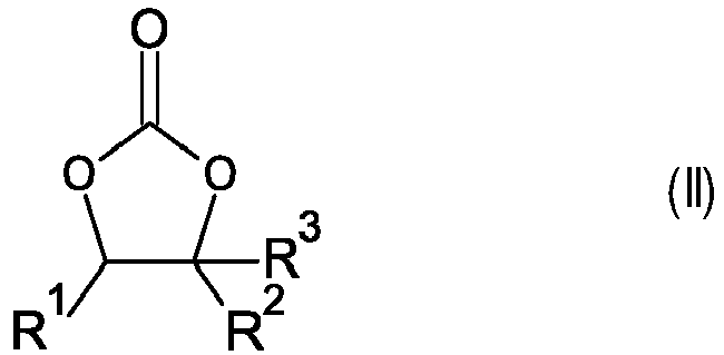

- In particularly preferred embodiments, R1 is methyl and R2 and R3 are each hydrogen, or R1, R2 and R3 are each hydrogen.
- Another preferred cyclic organic carbonate is vinylene carbonate, formula (IV).

- The solvent or solvents is/are preferably used in the water-free state, i.e. with a water content in the range from 1 ppm to 0.1% by weight, which can be determined, for example, by Karl-Fischer titration.
- Electrolyte (C) further comprises at least one electrolyte salt. Suitable electrolyte salts are, in particular, lithium salts. Examples of suitable lithium salts are LiPF6, LiBF4, LiClO4, LiAsF6, LiCF3SO3, LiC(CnF2n+1SO2)3, lithium imides such as LiN(CnF2n+1SO2)2, where n is an integer in the range from 1 to 20, LiN(SO2F)2, Li2SiF6, LiSbF6, LiAlCl4 and salts of the general formula (CnF2n+1SO2)tYLi, where m is defined as follows:
- t = 1, when Y is selected from among oxygen and sulfur,
- t = 2, when Y is selected from among nitrogen and phosphorus, and
- t = 3, when Y is selected from among carbon and silicon.
- Preferred electrolyte salts are selected from among LiC(CF3SO2)3, LiN(CF3SO2)2, LiPF6, LiBF4, LiClO4, with particular preference being given to LiPF6 and LiN(CF3SO2)2.
- In an embodiment of the present invention, batteries according to the invention comprise one or more separators by means of which the electrodes are mechanically separated. Suitable separators are polymer films, in particular porous polymer films, which are unreactive toward metallic lithium. Particularly suitable materials for separators are polyolefins, in particular film-forming porous polyethylene and film-forming porous polypropylene.
- Separators composed of polyolefin, in particular polyethylene or polypropylene, can have a porosity in the range from 35 to 45%. Suitable pore diameters are, for example, in the range from 30 to 500 nm.
- In another embodiment of the present invention, separators can be selected from among PET nonwovens filled with inorganic particles. Such separators can have porosities in the range from 40 to 55%. Suitable pore diameters are, for example, in the range from 80 to 750 nm.
- Batteries according to the invention further comprise a housing which can have any shape, for example cuboidal or the shape of a cylindrical disk or a cylindrical can. In one variant, a metal foil configured as a pouch is used as housing.
- Batteries according to the invention display a good discharge behavior, for example at low temperatures (zero °C or below, for example down to -10°C or even less), a very good discharge and cycling behavior.
- Batteries according to the invention can comprise two or more electrochemical cells that combined with one another, for example can be connected in series or connected in parallel. Connection in series is preferred. In batteries according to the present invention, at least one of the electrochemical cells contains at least one cathode according to the invention. Preferably, in electrochemical cells according to the present invention, the majority of the electrochemical cells contains a cathode according to the present invention. Even more preferably, in batteries according to the present invention all the electrochemical cells contain cathodes according to the present invention.
- The present invention further provides for the use of batteries according to the invention in appliances, in particular in mobile appliances. Examples of mobile appliances are vehicles, for example automobiles, bicycles, aircraft or water vehicles such as boats or ships. Other examples of mobile appliances are those which move manually, for example computers, especially laptops, telephones or electric hand tools, for example in the building sector, especially drills, battery-powered screwdrivers or battery-powered staplers.
- The invention is further illustrated by working examples.
- The electrodes were made in a dry room, dew point -40°C, moisture content below 500 ppm.
- The nanoparticulate oxides according to Table 1 were used as starting materials, steps (a.1) to (a.3).
Table 1: PSD measurements of nanoparticulate oxide starting materials Material Primary particle diameter [nm] d10 [µm] d50 [µm] d90 [µm] NiO 5 to 50 1.3 4.1 13.4 Co3O4 20 to 50 2.5 5.5 10.7 Mn3O4 20 to 100 1.5 12.4 33.2 All oxide starting materials from Table 1 were purchased from US Research Nanomaterials, Inc. - Step (b.1): 15.01 g (0.20 mol) NiO and 1.75 g (0.007 mol) Co3O4 provided in step (a.1) were mixed in a ball mill (SiO2 jar and SiO2 balls (10 mm diameter) for 30 min at 300 rpm. Then 9.32 g (0.22 mol) LiOH·H2O were added and mixed for additional 30 min in the ball mill at 300 rpm. Premix1 was obtained. Premix1 was then split into three portions of about equal size.
- Step (c1.1): The first portion was calcined in a muffle oven under a constant flow of oxygen atmosphere for 6 h at 700 °C. The heat rate was 3 °C/min. The resultant CAM1.1 was allowed to cool down to ambient temperature.
- Step (c1.2): The second portion of the Premix1 was calcined in the muffle oven under a constant flow of oxygen atmosphere for 6 h at 800 °C. The heat rate was 3 °C/min. The resultant CAM1.2 was allowed to cool down to ambient temperature.
- Step (c1.3): The third portion of the Premix1 was calcined in the muffle oven under a constant flow of oxygen atmosphere for 6 h at 900 °C. The heat rate was 3 °C/min. The resultant CAM1.3 was allowed to cool down to ambient temperature.
- Step (b.2): 14.99 g (0.20 mol) NiO and 1.65 g (0.007 mol) Mn3O4 were mixed in a ball mill (ZrO2 jar and ZrO2 balls (10 mm diameter) for 30 min at 300 rpm. Then 9.31 g (0.22 mol) LiOH·H2O were added and mixed for additional 30 min in the ball mill at 300 rpm. Premix2 was obtained. Premix2 was then split in three portions of about equal size.
- Step (c2.1): The first portion of Premix2 was calcined in a muffle oven under a constant flow of oxygen atmosphere for 6 h at 700 °C. The heat rate was of 3 °C/min. The resultant CAM2.1 was allowed to cool down to ambient temperature.
- Step (c2.2): The second portion of the Premix2 was calcined in the muffle oven under a constant flow of oxygen atmosphere for 6 h at 800 °C. The heat rate was of 3 °C/min. The resultant CAM2.2 was allowed to cool down to ambient temperature.
- Step (c2.3): The third portion of the Premix2 was calcined in the muffle oven under a constant flow of oxygen atmosphere for 6 h at 900 °C. The heat rate was 3 °C/min. The resultant CAM2.3 was allowed to cool down to ambient temperature.
- Step (b.3): 15.02 g (0.20 mol) NiO, 0.87 g (0.004 mol) Co3O4 and 0.83 g (0.004 mol) Mn3O4 were mixed in a ball mill (ZrO2 jar and ZrO2 balls (10 mm diameter) for 30 min at 300 rpm. Then 9.32 g (0.22 mol) LiOH·H2O were added and mixed for additional 30 min in the ball mill at 300 rpm. Premix3 was obtained. Premix3 was then split into three portions of about equal size.
- Step (c3.1): The first portion of Premix3 was calcined in a muffle oven under a constant flow of oxygen atmosphere for 6 h at 700 °C. The heat rate was of 3 °C/min. The resultant CAM3.1 was allowed to cool down to ambient temperature.
- Step (c3.2): The second portion of the Premix3 was calcined in the muffle oven under a constant flow of oxygen atmosphere for 6 h at 800 °C. The heat rate was of 3 °C/min. The resultant CAM3.2 was allowed to cool down to ambient temperature.
- Step (c3.3): The third portion of the Premix3 was calcined in the muffle oven under a constant flow of oxygen atmosphere for 6 h at 900 °C. The heat rate was of 3 °C/min. The resultant CAM3.3 was allowed to cool down to ambient temperature.
- Analytical properties of the inventive cathode active materials and of comparative cathode active materials are summarized in Table 2.
Table 2: analytical properties of comparative and inventive cathode active materials Sample Composition Step (c) [°C] Li [wt%] Ni [wt%] Co [wt%] Mn [wt%] LiOH [wt%] Li2CO3 [wt%] c-CAM1.1 NC9010 700 7.27 52.1 6.15 0 0.8594 0.348 c-CAM1.2 NC9010 800 7.09 52.18 6.04 0 0.6678 0.3088 c-CAM1.3 NC9010 900 6.87 53.07 6.11 0 1.553 0.2527 CAM1.1 NC9010 700 7.02 52.39 5.95 0 0.7881 0.5116 CAM1.2 NC9010 800 6.85 52.83 6.03 0 0.4582 0.2584 CAM1.3 NC9010 900 7.06 53.17 6.05 0 2.8062 0.2138 c-CAM2.1 NM9010 700 7.04 52.53 0 5.43 1.8034 0.9386 c-CAM2.2 NM9010 800 6.92 53.41 0 5.46 0.6364 0.1994 c-CAM2.3 NM9010 900 6.89 53.32 0 5.5 1.2776 0.191 CAM2.1 NM9010 700 7.04 52.27 0 5.36 1.2001 0.7583 CAM2.2 NM9010 800 6.79 49.52 0 5.09 0.3973 0.4555 CAM2.3 NM9010 900 7.21 53.05 0 5.43 2.3179 0.5206 c-CAM3.1 NCM9055 700 7.07 53.2 2.37 2.75 1.4195 1.1182 c-CAM3.2 NCM9055 800 7.04 53.1 2.37 2.75 1.4323 1.1651 c-CAM3.3 NCM9055 900 6.99 54.04 2.4 2.79 1.2249 0.645 CAM3.1 NCM9055 700 7.27 52.39 2.87 2.73 1.0655 1.0821 CAM3.2 NCM9055 800 7.32 52.26 2.88 2.74 1.1608 0.7247 CAM3.3 NCM9055 900 7.02 53.32 2.96 2.8 2.0288 0.6855 - The following aqueous solutions were provided:
- solution (α1): NiSO4 and CoSO4 dissolved in deionized water (molar ratio 9:1, total transition metal concentration: 1.65 mol/kg)
- Solution (α2): α) NiSO4 and MnSO4 dissolved in deionized water (molar ratio 9:1, total transition metal concentration: 1.65 mol/kg)
- Solution (α3): NiSO4, CoSO4 and MnSO4 dissolved in deionized water (molar ratio 91:04:05, total transition metal concentration: 1.65 mol/kg)
- Solution (β1): 25wt% NaOH dissolved in deionized water
- Solution (γ1): of 25wt% ammonia in deionized water
- A 3.2 I-stirred tank reactor was charged with 1.6 I deionized water containing 33 g ammonia and heated to 55 °C under nitrogen atmosphere. Subsequently, solution (β1) and solution (α1) was added in a way that the pH value at 23 °C was set to 12.05 and the stirrer was set to 1000 rpm. The tank reactor was then fed with solutions (α1), (β1) and (γ1) in a way that the pH value of the mother liquor was 12.05 and the molar ratio of NH3 to the sum of Ni and Co in the reactor was 0.55. Mother liquor was separated from the solid and removed from the reactor by a clarifier attached to the top of the reactor. The individual flow rates of the solutions were adjusted to meet a residence time of 5 h. The stirrer speed was kept constant. The reaction was conducted for 18 hours. A hydroxide with a mean particle size (d50) = 11.0 µm was obtained and separated by filtration, washed with deionized water and an aqueous solution of sodium hydroxide (1kg solution (β1) per kg of filter cake) and dried at 120 °C for 16 hours to obtain the comparative precursor c-P-CAM1 with molar composition of Ni:Co = 89.3:10.7, an average particle size (d50) = 11.1 µm and span = 0.7.
- Solution (α2), solution (β1) and solution (γ1) were simultaneously introduced into a 3.2 I-stirred tank reactor through the separate tubes. The molar ratio between ammonia and transition metal was adjusted to 0.15. The sum of volume flows was set to adjust the mean residence time to 5 hours. The flow rate of solution (β1) was adjusted by a pH regulation circuit to keep the pH value at 23 °C in the stirred tank reactor at a constant value of 12.1. The tank reactor was operated continuously keeping the liquid level in the tank reactor constant. A mixed hydroxide of Ni and Mn was collected via free overflow from the vessel. The resulting slurry contained about 120g/l mixed hydroxide of Ni and Mn. The slurry was filtered and the filter cake was washed with deionized water and 1 kg of solution (β1) per kg of solid hydroxide) and dried at 120 °C for 16 hours to obtain the comparative precursor c-P-CAM2 with molar composition of Ni:Mn = 90.2:9.8, an average particle size (d50) = 10.1 µm and span = 1.22.
- Solution (α3) solution (β1) and solution (γ1) were simultaneously introduced into a 3.2 I-stirred tank reactor through separate tubes. The molar ratio between ammonia and transition metal was adjusted to 0.25. The sum of volume flows was set to adjust the mean residence time to 5 hours. The flow rate of solution (β1) was adjusted by a pH regulation circuit to keep the pH value in the stirred tank reactor at a constant value of 117. The tank reactor was operated continuously keeping the liquid level in the tank reactor constant. A mixed hydroxide of Ni, Co and Mn was collected via free overflow from the vessel. The resulting slurry contained about 120g/l mixed hydroxide of Ni, Co and Mn. The slurry was filtered, the filter cake was washed with deionized water and an aqueous solution of sodium hydroxide (1kg of solution (β1) per kg of solid hydroxide) and dried at 120 °C for 16 hours to obtain the comparative precursor c-P-CAM3 with molar composition of Ni:Co:Mn = 91.0:4.0:5.0, an average particle size (d50) = 10.6 µm and span = 1.26.
- c-P-CAM1 was mixed with lithium hydroxide monohydrate using a molar ratio of Li : (Ni+Co) = 1.02 to obtain the Premix-c1. Premix-c1 was then split into three portions of about equal size.
- The first portion of Premix-c1 was calcined in a muffle oven under a constant flow of oxygen atmosphere for 6 h at 700 °C. The heating rate was of 3 °C/min. The resultant c-CAM1.1 was allowed to cool down to ambient temperature.
- The second portion of Premix-c1 was calcined in a muffle oven under a constant flow of oxygen atmosphere for 6 h at 800 °C. The heating rate was of 3 °C/min. The resultant c-CAM1.2 was allowed to cool down to ambient temperature.
- The third portion of Premix-c1 was calcined in a muffle oven under a constant flow of oxygen atmosphere for 6 h at 900 °C. The heating rate was of 3 °C/min. The resultant c-CAM1.3 was allowed to cool down to ambient temperature.
- c-P-CAM2 was mixed with lithium hydroxide monohydrate using a molar ratio of Li : (Ni+Co) = 1.02 to obtain the Premix-c2. Premix-c2 was then split into three portions of about equal size.
- The first portion of Premix-c2 was calcined in a muffle oven under a constant flow of oxygen atmosphere for 6 h at 700 °C. The heating rate was of 3 °C/min. The resultant c-CAM2.1 was allowed to cool down to ambient temperature.
- The second portion of Premix-c2 was calcined in a muffle oven under a constant flow of oxygen atmosphere for 6 h at 800 °C. The heating rate was of 3 °C/min. The resultant c-CAM2.2 was allowed to cool down to ambient temperature.
- The third portion of Premix-c2 was calcined in a muffle oven under a constant flow of oxygen atmosphere for 6 h at 900 °C. The heating rate was of 3 °C/min. The resultant c-CAM2.3 was allowed to cool down to ambient temperature.
- c-P-CAM3 was mixed with lithium hydroxide monohydrate using a molar ratio of Li : (Ni+Co) = 1.02 to obtain the Premix-c2. Premix-c2 was then split into three portions of about equal size.
- The first portion of Premix-c3 was calcined in a muffle oven under a constant flow of oxygen atmosphere for 6 h at 700 °C. The heating rate was of 3 °C/min. The resultant c-CAM3.1 was allowed to cool down to ambient temperature.
- The second portion of Premix-c3 was calcined in a muffle oven under a constant flow of oxygen atmosphere for 6 h at 800 °C. The heating rate was of 3 °C/min. The resultant c-CAM3.2 was allowed to cool down to ambient temperature.
- The third portion of Premix-c3 was calcined in a muffle oven under a constant flow of oxygen atmosphere for 6 h at 900 °C. The heating rate was of 3 °C/min. The resultant c-CAM3.3 was allowed to cool down to ambient temperature.
Table 3: Sulfur and sodium analytics c-CAM1.2 CAM1.2 c-CAM2.2 CAM2.2 c-CAM3.2 CAM3.2 S [% wt] 0.2 0.01 0.14 0.03 0.17 0.02 Sulfate [%wt] 0.6 0.02 0.43 0.1 0.5 0.06 Na [% wt] 0.015 0.037 0.015 0.073 0.023 0.056 S was determined by coulometry, sulfate by IC. - Cathode manufacture: Cathodes contained 94% of the respective CAM or C-CAM, 3% carbon black (Super C65) and 3% binder (polyvinylidene fluoride, Solef 5130). Slurries with a total solids content of 61% were mixed in N-methyl-2-pyrrolidone (planetary mixer, 24 minutes, 2,000 rpm) and cast onto aluminum foil tape by a box-type coater. After drying of the electrode tapes for 16 h at 120 °C in vacuo and calendaring, circular electrodes with a diameter of 14 mm were punched, weighed and dried at 120 °C under vacuum for 12 hours before entering in an Ar filled glove box. Average loading: 8 mg/cm2, electrode density: 3 g/cm3.
- Coin-type electrochemical half-cells were assembled in an argon-filled glovebox. Anode: 0.58 mm thick Li foil, separated from the cathode by a glass fiber separator (Whatman GF/D). An amount of 95 µl of 1 M LiPF6 in ethylene carbonate (EC): ethylmethyl carbonate (EMC), 3:7 by weight, was used as the electrolyte. After assembly, the cells were crimped closed in an automated crimper. The cells were then transferred to a climate chamber and connected to a battery cycler (Series4000, MACCOR).
- All tests were performed at 25 °C. Cells were galvanostatically cycled at a Maccor 4000 battery cycler between 3.1 and 4.3 V at room temperature by applying the following C-rates until 70 % of the initial discharge capacity is reached at a certain discharge step:
The test protocol consisted of an initial formation & rate test part, starting with two cycles at C/10. For all cycles, the voltage window was set to 3.0 - 4.3 V. As an initial 1C rate, 200 mA g-1 were assumed.Table 4: Electrochemical results of inventive and comparative examples CAM Cell Charge Capacity [mA·h/g] Discharge Capacity [mA·h/g] CAM1.1 BAT1.1 234.2 210.1 c-CAM1.2 c-BAT1.2 215.2 186.7 CAM1.2 BAT1.2 214.0 187.3 CAM1.3 BAT1.3 223.2 192.6 c-CAM2.1 c-BAT2.1 238.4 209.9 CAM2.1 BAT2.1 240.2 213.4 c-CAM2.2 c-BAT2.2 234.9 192.6 CAM2.2 BAT2.2 235.8 205.1 CAM2.3 BAT2.3 236.4 207.2 c-CAM3.1 c-BAT3.1 221.6 180.0 CAM3.1 BAT3.3 222.4 179.3 c-CAM3.2 c-BAT3.2 222.1 181.1 CAM3.2 BAT3.2 225.4 185.5 CAM3.3 BAT3.3 224.3 184.1
Claims (14)
- Process for making a particulate compound according to general formula Li1+xTM1-xO2 with x being in the range of from -0.02 to +0.15 and with TM representing nickel and at least one metal selected from Co and Mn and, optionally, including at least one of Al, Mg, Ti, Zr, Nb, Ta, Mo, and W, wherein said process comprises the steps of:(a) providing a nanoparticulate oxide or (oxy)hydroxide of each of the metals of TM,(b) mixing the nanoparticulate oxides or (oxy)hydroxides in the stoichiometry targeted for TM under addition of a source of lithium selected from LiOH and Li2CO3 and Li2O2 and Li2O, and(c) treating the mixture from step (b) at a temperature in the range of from 700 to 950°C.
- Process according to claim 1 wherein step (b) is performed in a ball mill, agitating mill, high-shear mixer, or extruder.
- Process according to claim 1 or 2 wherein TM is a combination of metals according to general formula (I)
(NiaCobMnc)1-dMd (I)
with
a being in the range of from 0.6 to 0.98,
b being in the range of from zero to 0.2,
c being in the range of from zero to 0.25, and
d being in the range of from zero to 0.1,
M is selected from Mg, Al, Ti, Zr, Mo, W, Nb, and Ta,
a + b + c = 1, and b + c > 0. - Process according to any of the preceding claims wherein said oxides and (oxy)hydroxides provided in step (a) is in the form of aggregates that have an average particle diameter (D50) in the range of from 1 to 10 µm.
- Process according to any of the preceding claims wherein oxide of Mn is provided as Mn2O3 or Mn3O4 in nanoparticulate form.
- Process according to any of the preceding claims wherein said particulate oxide is form of agglomerates of primary particles with irregular shape and a mass weighted equivalent diameter in the range of from 0.4 to 3 µm.
- Process according to any of the preceding claims wherein a subsequent water treatment step (d) or a subsequent coating step (e) is performed.
- Process according to claim 7 wherein in a coating step (e), a layer of an oxide compound of Al, Co or Zr or a boron oxide/borate is applied to said particulate compound.
- Particulate composite oxide of general formula Li1+xTM1-xO2 with x being in the range of from -0.02 to +0.15 and with TM representing nickel and at least one metal selected from Co and Mn and, optionally, including at least one of Al, Mg, Ti, Zr, Nb, Ta, Mo, and W, wherein said particulate composite oxide is in the form of agglomerates of primary particles with irregular shape and a mass weighted equivalent diameter in the range of from 0.4 to 3 µm and a span (d90)-(d10) divided by (d50) in the range of from and wherein said agglomerates have an irregular shape and an average diameter in the range of from 2 to 10 µm and a sulfate content in the range of from 50 to 500 ppm.
- Particulate composite oxide according to claim 9 wherein TM is a combination of metals according to general formula (I)
(NiaCobMnc)1-dMd (I)
with
a being in the range of from 0.6 to 0.98,
b being in the range of from zero to 0.2,
c being in the range of from zero to 0.25, and
d being in the range of from zero to 0.1,
M is selected from Mg, Al, Ti, Zr, Mo, W, Nb, and Ta,
a + b + c = 1, and b + c > 0. - Particulate composite oxide according to claim 9 or 10 wherein said composite is at least partially coated with at least one oxide compound of Al, Co, Zr, or a boron oxide/borate.
- Particulate compound according to any of claims 9 to 11 wherein such compound has a sodium content in the range of from 50 to 500 ppm.
- Cathode comprising(A) at least one particulate composite oxide according to any of the claims 9 to 12,(B) carbon in electrically conductive form,(C) at least one binder.
- Electrochemical cell comprising a cathode according to claim 13.
Priority Applications (1)
| Application Number | Priority Date | Filing Date | Title |
|---|---|---|---|
| EP21176525.0A EP4095102A1 (en) | 2021-05-28 | 2021-05-28 | Process for making a particulate electrode active material, and electrode active material |
Applications Claiming Priority (1)
| Application Number | Priority Date | Filing Date | Title |
|---|---|---|---|
| EP21176525.0A EP4095102A1 (en) | 2021-05-28 | 2021-05-28 | Process for making a particulate electrode active material, and electrode active material |
Publications (1)
| Publication Number | Publication Date |
|---|---|
| EP4095102A1 true EP4095102A1 (en) | 2022-11-30 |
Family
ID=76180950
Family Applications (1)
| Application Number | Title | Priority Date | Filing Date |
|---|---|---|---|
| EP21176525.0A Withdrawn EP4095102A1 (en) | 2021-05-28 | 2021-05-28 | Process for making a particulate electrode active material, and electrode active material |
Country Status (1)
| Country | Link |
|---|---|
| EP (1) | EP4095102A1 (en) |
Cited By (1)
| Publication number | Priority date | Publication date | Assignee | Title |
|---|---|---|---|---|
| US12378132B2 (en) | 2019-08-29 | 2025-08-05 | Novonix Battery Technology Solutions Inc. | Lithium transition metal oxide and precursor particulates and methods |
Citations (10)
| Publication number | Priority date | Publication date | Assignee | Title |
|---|---|---|---|---|
| US20020110736A1 (en) | 2000-09-25 | 2002-08-15 | Kweon Ho-Jin | Positive active material for rechargeable lithium batteries and method for preparing same |
| EP2006937A2 (en) * | 2006-04-07 | 2008-12-24 | Mitsubishi Chemical Corporation | Lithium transition metal-based compound powder for positive electrode material in lithium rechargeable battery, method for manufacturing the powder, spray dried product of the powder, firing precursor of the powder, and positive electrode for lithium rechargeable battery and lithium rechargeable battery using the powder |
| US20170012284A1 (en) * | 2015-07-10 | 2017-01-12 | California Institute Of Technology | Aluminum borate coated lithium ion cathode materials |
| US20170084919A1 (en) * | 2014-05-27 | 2017-03-23 | Dow Global Technologies Llc | Improved lithium metal oxide cathode materials and method to make them |
| US20170256789A1 (en) * | 2014-09-23 | 2017-09-07 | Dow Global Technologies Llc | Lithium metal oxide containing batteries having improved rate capability |
| CN109279659A (en) * | 2018-08-22 | 2019-01-29 | 中伟新材料有限公司 | A kind of preparation method of single crystal ternary positive electrode material |
| WO2020069882A1 (en) * | 2018-10-02 | 2020-04-09 | Basf Se | Process for making a partially coated electrode active material |
| US20210013506A1 (en) | 2018-03-13 | 2021-01-14 | Sumitomo Chemical Company, Limited | Lithium metal composite oxide powder, positive electrode active material for lithium secondary batteries, positive electrode, and lithium secondary battery |
| WO2021040931A1 (en) * | 2019-08-29 | 2021-03-04 | Novonix Battery Testing Services Inc. | Lithium transition metal oxide and precursor particulates and methods |
| US20210143423A1 (en) * | 2018-03-29 | 2021-05-13 | Umicore | Methods for preparing positive electrode material for rechargeable lithium ion batteries |
-
2021
- 2021-05-28 EP EP21176525.0A patent/EP4095102A1/en not_active Withdrawn
Patent Citations (10)
| Publication number | Priority date | Publication date | Assignee | Title |
|---|---|---|---|---|
| US20020110736A1 (en) | 2000-09-25 | 2002-08-15 | Kweon Ho-Jin | Positive active material for rechargeable lithium batteries and method for preparing same |
| EP2006937A2 (en) * | 2006-04-07 | 2008-12-24 | Mitsubishi Chemical Corporation | Lithium transition metal-based compound powder for positive electrode material in lithium rechargeable battery, method for manufacturing the powder, spray dried product of the powder, firing precursor of the powder, and positive electrode for lithium rechargeable battery and lithium rechargeable battery using the powder |
| US20170084919A1 (en) * | 2014-05-27 | 2017-03-23 | Dow Global Technologies Llc | Improved lithium metal oxide cathode materials and method to make them |
| US20170256789A1 (en) * | 2014-09-23 | 2017-09-07 | Dow Global Technologies Llc | Lithium metal oxide containing batteries having improved rate capability |
| US20170012284A1 (en) * | 2015-07-10 | 2017-01-12 | California Institute Of Technology | Aluminum borate coated lithium ion cathode materials |
| US20210013506A1 (en) | 2018-03-13 | 2021-01-14 | Sumitomo Chemical Company, Limited | Lithium metal composite oxide powder, positive electrode active material for lithium secondary batteries, positive electrode, and lithium secondary battery |
| US20210143423A1 (en) * | 2018-03-29 | 2021-05-13 | Umicore | Methods for preparing positive electrode material for rechargeable lithium ion batteries |
| CN109279659A (en) * | 2018-08-22 | 2019-01-29 | 中伟新材料有限公司 | A kind of preparation method of single crystal ternary positive electrode material |
| WO2020069882A1 (en) * | 2018-10-02 | 2020-04-09 | Basf Se | Process for making a partially coated electrode active material |
| WO2021040931A1 (en) * | 2019-08-29 | 2021-03-04 | Novonix Battery Testing Services Inc. | Lithium transition metal oxide and precursor particulates and methods |
Non-Patent Citations (1)
| Title |
|---|
| ZHANG MAOLIN ET AL: "Effect of micron sized particle on the electrochemical properties of nickel-rich LiNi0.8Co0.1Mn0.1O2 cathode materials", CERAMICS INTERNATIONAL, ELSEVIER, AMSTERDAM, NL, vol. 46, no. 4, 23 October 2019 (2019-10-23), pages 4643 - 4651, XP086007041, ISSN: 0272-8842, [retrieved on 20191023], DOI: 10.1016/J.CERAMINT.2019.10.195 * |
Cited By (2)
| Publication number | Priority date | Publication date | Assignee | Title |
|---|---|---|---|---|
| US12378132B2 (en) | 2019-08-29 | 2025-08-05 | Novonix Battery Technology Solutions Inc. | Lithium transition metal oxide and precursor particulates and methods |
| US12434978B2 (en) | 2019-08-29 | 2025-10-07 | Novonix Battery Technology Solutions Inc. | Microgranulation methods and product particles therefrom |
Similar Documents
| Publication | Publication Date | Title |
|---|---|---|
| JP7443379B2 (en) | Method for manufacturing electrode active material | |
| EP4461705B1 (en) | Process for making an electrode active material, and electrode active material | |
| US20210367222A1 (en) | Process for making an at least partially coated electrode active material | |
| EP4149889B1 (en) | Process for making a particulate (oxy)hydroxide, and electrode active material made therefrom | |
| EP3902037A1 (en) | Process for making a cathode active material for lithium ion batteries, and cathode active material | |
| EP3631883B1 (en) | Process for making an electrode active material | |
| EP4247760B1 (en) | Multi-step process for making cathode active materials, and cathode active materials | |
| US20210387864A1 (en) | Process for making lithiated transition metal oxide particles, and particles manufactured according to said process | |
| US20240266524A1 (en) | Cathodes for lithium ion batteries and method for manufacturing such cathodes | |
| EP4095102A1 (en) | Process for making a particulate electrode active material, and electrode active material | |
| EP4229693B1 (en) | Process for making a coated cathode active material | |
| EP4176476B1 (en) | Coated particulate electrode active materials | |
| JP2025510202A (en) | Method for producing doped cathode active material | |
| WO2023066740A1 (en) | Process for making a coated electrode active material, and coated electrode active material | |
| EP4074660A1 (en) | Process for making an electrode active material, and electrode active material | |
| JP2023547996A (en) | Method for manufacturing doped cathode active material | |
| EP4482795B1 (en) | Process for making a coated electrode active material, and coated electrode active material | |
| EP4110733B1 (en) | Process for making an electrode active material, and electrode active material | |
| WO2025061478A1 (en) | Process for making a cathode active material, and cathode active material | |
| WO2025078192A1 (en) | Method of making a precursor for a cathode active material | |
| EP4677657A1 (en) | Cathode active materials with a core-shell structure and their manufacture | |
| WO2024208775A1 (en) | Cathode active materials comprising cobalt, and way of manufacture | |
| KR20250170055A (en) | Cathode active material for lithium-ion batteries and method for manufacturing same | |
| JP2024502936A (en) | Method for manufacturing electrode active material |
Legal Events
| Date | Code | Title | Description |
|---|---|---|---|
| PUAI | Public reference made under article 153(3) epc to a published international application that has entered the european phase |
Free format text: ORIGINAL CODE: 0009012 |
|
| STAA | Information on the status of an ep patent application or granted ep patent |
Free format text: STATUS: THE APPLICATION HAS BEEN PUBLISHED |
|
| AK | Designated contracting states |
Kind code of ref document: A1 Designated state(s): AL AT BE BG CH CY CZ DE DK EE ES FI FR GB GR HR HU IE IS IT LI LT LU LV MC MK MT NL NO PL PT RO RS SE SI SK SM TR |
|
| STAA | Information on the status of an ep patent application or granted ep patent |
Free format text: STATUS: THE APPLICATION HAS BEEN WITHDRAWN |
|
| 18W | Application withdrawn |
Effective date: 20221206 |