EP4095080A1 - Holding brake monitoring circuit system, elevator system and holding brake monitoring method - Google Patents
Holding brake monitoring circuit system, elevator system and holding brake monitoring method Download PDFInfo
- Publication number
- EP4095080A1 EP4095080A1 EP21213529.7A EP21213529A EP4095080A1 EP 4095080 A1 EP4095080 A1 EP 4095080A1 EP 21213529 A EP21213529 A EP 21213529A EP 4095080 A1 EP4095080 A1 EP 4095080A1
- Authority
- EP
- European Patent Office
- Prior art keywords
- holding
- holding brake
- polarity
- opening sensor
- output signal
- Prior art date
- Legal status (The legal status is an assumption and is not a legal conclusion. Google has not performed a legal analysis and makes no representation as to the accuracy of the status listed.)
- Withdrawn
Links
- 238000012544 monitoring process Methods 0.000 title claims abstract description 83
- 238000000034 method Methods 0.000 title claims abstract description 18
- 238000012423 maintenance Methods 0.000 description 3
- 230000000630 rising effect Effects 0.000 description 3
- 230000008901 benefit Effects 0.000 description 2
- 238000013461 design Methods 0.000 description 2
- 238000001514 detection method Methods 0.000 description 2
- 238000010586 diagram Methods 0.000 description 2
- 238000012545 processing Methods 0.000 description 2
- 238000006467 substitution reaction Methods 0.000 description 2
- 230000002159 abnormal effect Effects 0.000 description 1
- 238000004891 communication Methods 0.000 description 1
- 230000036544 posture Effects 0.000 description 1
Images




Classifications
-
- B—PERFORMING OPERATIONS; TRANSPORTING
- B66—HOISTING; LIFTING; HAULING
- B66B—ELEVATORS; ESCALATORS OR MOVING WALKWAYS
- B66B5/00—Applications of checking, fault-correcting, or safety devices in elevators
-
- B—PERFORMING OPERATIONS; TRANSPORTING
- B66—HOISTING; LIFTING; HAULING
- B66B—ELEVATORS; ESCALATORS OR MOVING WALKWAYS
- B66B5/00—Applications of checking, fault-correcting, or safety devices in elevators
- B66B5/0006—Monitoring devices or performance analysers
- B66B5/0037—Performance analysers
-
- B—PERFORMING OPERATIONS; TRANSPORTING
- B66—HOISTING; LIFTING; HAULING
- B66B—ELEVATORS; ESCALATORS OR MOVING WALKWAYS
- B66B5/00—Applications of checking, fault-correcting, or safety devices in elevators
- B66B5/0006—Monitoring devices or performance analysers
- B66B5/0018—Devices monitoring the operating condition of the elevator system
- B66B5/0025—Devices monitoring the operating condition of the elevator system for maintenance or repair
-
- F—MECHANICAL ENGINEERING; LIGHTING; HEATING; WEAPONS; BLASTING
- F16—ENGINEERING ELEMENTS AND UNITS; GENERAL MEASURES FOR PRODUCING AND MAINTAINING EFFECTIVE FUNCTIONING OF MACHINES OR INSTALLATIONS; THERMAL INSULATION IN GENERAL
- F16D—COUPLINGS FOR TRANSMITTING ROTATION; CLUTCHES; BRAKES
- F16D66/00—Arrangements for monitoring working conditions, e.g. wear, temperature
-
- G—PHYSICS
- G01—MEASURING; TESTING
- G01R—MEASURING ELECTRIC VARIABLES; MEASURING MAGNETIC VARIABLES
- G01R19/00—Arrangements for measuring currents or voltages or for indicating presence or sign thereof
- G01R19/14—Indicating direction of current; Indicating polarity of voltage
Definitions
- the present application relates to the field of elevators, and specifically to a holding brake monitoring circuit system, an elevator system, and a holding brake monitoring method.
- the holding brake monitoring circuit system is an effective method to monitor whether the holding brake of the elevator works normally.
- the existing monitoring circuit collects the opening and closing status of each micro switch corresponding to the holding brake, and judges whether each holding brake is working normally based on this, and then judges whether the holding brake system comprising multiple holding brakes is working normally.
- this method usually needs to scan the output signal of each micro switch, which is sometimes inefficient.
- this will also occupy a large number of ports of the judgment circuit. In some cases, the number of ports may limit the number of micro switches that can be configured.
- embodiments of the present application provide a holding brake monitoring circuit system, an elevator system, and a holding brake monitoring method, which can monitor working status of the holding brake of the elevator in a group manner to improve the efficiency of monitoring.
- a holding brake monitoring circuit system comprising: a plurality of opening sensors corresponding to holding brakes, wherein the number of the opening sensors is an even number greater than 3, and the opening sensors are configured to be paired to form at least two working groups, and each of the working groups is configured to output an output signal for judging status of the holding brake(s).
- one of the holding brakes is configured to be coupled to two of the opening sensors which are paired into a working group, and each of the remaining holding brakes is configured to be coupled to respective one of the opening sensors.
- each of the holding brakes is configured to be coupled to respective one of the opening sensors.
- each of the opening sensors has a basic polarity, a normally closed polarity, and an operation polarity; for each of the opening sensors being not in operation, its basic polarity is turned on and its normally closed polarity or operation polarity is turned on; and for each of the opening sensors being in normal operation, its basic polarity is turned on and its operation polarity or normally closed polarity is turned on.
- each of the working groups is connected in series.
- the basic polarities of the two opening sensors in each of the working group are connected; when being connected in series, the normally closed polarity of the first opening sensor of the first working group is connected to the high potential, and the operation polarity of the second opening sensor is also connected to the high potential, the normally closed polarity of the second opening sensor is for the next working group to be connected; and the first part of the output signal is generated based on the operation polarity of the first opening sensor of the first working group.
- the normally closed polarity of the first opening sensor of each of the working groups is connected to the previous working group, and the operation polarity of the second opening sensor is connected to the high potential; and the second part of the output signal is generated based on the operation polarity of the first opening sensor of each of the working groups.
- the third part of the output signal is generated based on the normally closed polarity of the second opening sensor of the last working group in the serial connection.
- a logical AND gate configured to receive the first part and the second part of the output signal and output the fourth part of the output signal.
- the holding brake monitoring circuit system further comprises a power supply device configured to provide the high potential.
- the opening sensors are micro switches.
- the holding brake monitoring circuit system further comprises a judgment circuit configured to determine status of the holding brakes according to the output signal.
- an elevator system comprising any one of the holding brake monitoring circuit systems described above.
- a holding brake monitoring method comprising: pairing a plurality of opening sensors corresponding to holding brakes to form at least two working groups, wherein the number of the opening sensors is an even number greater than 3; and forming an output signal for judging status of the holding brakes according to each of the working groups.
- the step of pairing the opening sensors comprises: if the number of the holding brakes is an odd number, one of the holding brakes is configured to be coupled to two of the opening sensors which are paired into a working group, and each of the remaining holding brakes is configured to be coupled to respective one of the opening sensors.
- the step of pairing the opening sensors comprises: if the number of the holding brakes is an even number, each of the holding brakes is configured to be coupled to respective one of the opening sensors.
- the holding brake monitoring circuit system and the elevator system comprising the holding brake monitoring circuit system can monitor working status of the holding brake of the elevator in a group manner, thereby overcoming the inefficiency problem of the need to scan the output signal of each micro switch.
- the requirements for the number of ports of the processing circuit board can also be reduced.
- the present application mainly refers to its exemplary embodiments to describe the principles of the present application.
- the same principle can be equally applied to all types of holding brake monitoring circuit systems, elevator systems, and holding brake monitoring methods, and these same or similar principles can be implemented therein, any such changes do not depart from the true spirit and scope of the present application.
- generating an output signal based on a polarity means generating an output signal based on a level characteristic of the polarity.
- the output signal may comprise multiple sources, which are described as various parts of the output signal in the present application.
- the monitoring result of the holding brake monitoring circuit system may be output according to the output signal or part thereof.
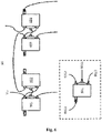
- FIG. 1 shows the principle of a holding brake monitoring circuit system according to the prior art.
- a holding brake system 10 comprises four holding brakes, and each of the holding brakes is coupled to a micro switch.
- the micro switches 101-104 can be respectively used to detect whether the corresponding brake is operating. Although four micro switches are shown in the figure, there may be more than four or less than four in the actual situation.
- the micro switch 102 (two poles therein) is in an open status, and at the same time in a low level outward; if the brake corresponding to the micro switch 102 works, the micro switch 102 (two poles therein) is in a closed status, and at the same time in a high level outward.
- the output signals of the micro switches 101-104 are input to the four input ports 111-114 of a judgment circuit 11, respectively.
- the judgment circuit 11 can judge the opening and closing status of each of the micro switches 101-104 according to the signals received by the four input ports, and judge whether each holding brake is working normally based on this, and then judge whether the holding brake system 10 is working normally.
- the judgment circuit 11 can issue an instruction to the elevator, and the elevator can, for example, stop at a closer floor and suspend operation according to the instruction.
- the information that the holding brake system 10 does not work normally can be sent to a maintenance unit through a communication network, so as to remind the maintenance unit to check and repair as soon as possible.
- each micro switch corresponds to a holding brake
- the judgment circuit 11 needs to scan the output signal of each micro switch to judge the working status of the holding brake system 10. This method is sometimes inefficient, because even if a holding brake works abnormally, it needs to be repaired immediately. Under normal circumstances, the maintenance personnel do not need to know which holding brake is abnormal before arriving at the scene.
- the output of each micro switch is introduced into the judgment circuit 11, this will also occupy a large number of ports of the judgment circuit 11, especially when there are a large number of holding brakes. Therefore, chips with a larger number of ports may be needed to implement the function of the judgment circuit 11, thus the cost will also increase.
- a holding brake monitoring circuit system comprising an opening sensor corresponding to the holding brake.
- the opening sensor in the context of the present application refers to a sensor that can detect the opening status of the holding brake, and it can judge whether the holding brake is operating according to the detection situation. For example, when the holding brake is in a slack status, its opening is larger; when the holding brake is operating, its opening is smaller.
- the opening sensor in some examples of the present application does not detect the specific value of the opening, and it can judge whether the holding brake is in an operating status according to a set threshold (for example, by configuring different gaps).
- the opening sensor in some examples of the present application may be implemented with a micro switch or the like.
- the number of opening sensors is usually set to an even number and greater than 3. Therefore, for the case of less than 3, there is no need to address in a group manner described below.
- These even number of opening sensors are configured to pair two as a group, and generate output signals for judging the status of the holding brake in units of groups.
- These paired groups are also referred to as "working groups" in the context of the present application.
- the output signal can be sent to, for example, the judgment circuit 11 in FIG. 1 , and the judgment circuit 11 specifically judges the status of the holding brake.
- the judgment circuit 11 may not necessarily judge the status of each holding brake, but judge the status of the holding brake group, and thereby infer the status of the holding brake system.
- this grouping method can significantly reduce the port occupation of the judgment circuit 11, for example, to about one-half of the original required number of ports.
- FIGS. 2 and 3 there are four opening sensors in the holding brake monitoring circuit system 20 and the holding brake monitoring circuit system 30.
- the opening sensor 201 is paired with the opening sensor 202, and the opening sensor 203 is paired with the opening sensor 204, thereby forming two groups of pairs.
- the output signal 212 and the output signal 213 of the holding brake monitoring circuit system 20 respectively correspond to the above-mentioned two groups of pairs, so that the output signal can be generated in units of groups.
- the "single-pole double-throw" characteristics of the paired opening sensor can be used to pair two opening sensors, so that only when both of them are switched to the same status at the same time, it means that holding brakes corresponding to both of them are working normally, or the groups that both of them belong to are working normally.
- connection mode of the opening sensor 201 and the opening sensor 202 in FIGS. 2 and 3 shows a circuit connection diagram that uses the "single-pole double-throw" characteristics of the two, and the operating status of the opening sensor of this group and its corresponding holding brake can be judged from the output signal 212.
- the other groups can be connected according to the connection mode of the opening sensor 201 and the opening sensor 202. In addition, the difference between the examples corresponding to FIG. 2 and FIG. 3 will be described below.
- FIGS. 7 and 8 there are 6 opening sensors in the holding brake monitoring circuit system 70 and the holding brake monitoring circuit system 80.
- the opening sensor 201 is paired with the opening sensor 202
- the opening sensor 203 is paired with the opening sensor 204
- the opening sensor 705 is paired with the opening sensor 706, thereby forming a total of three groups of pairs
- the output signal 212, the output signal 213, and the output signal 714 of the holding brake monitoring circuit system 70 respectively correspond to the above-mentioned three groups of pairs, so that the output signal can be generated in units of groups.
- the "single-pole double-throw" characteristics of the paired opening sensor can be used to pair two opening sensors, so that only when both of them are switched to the same status at the same time, it means that holding brakes corresponding to both of them are working normally, or the groups that both of them belong to are working normally.
- connection mode of the opening sensor 201 and the opening sensor 202 shows a circuit connection diagram that uses the "single-pole double-throw" characteristics of the two, and the operating status of the opening sensor of this group and its corresponding holding brake can be judged from the output signal 212.
- the other groups (the pair of the opening sensor 203 and the opening sensor 204, and the pair of the opening sensor 705 and the opening sensor 706) can be connected according to the connection mode of the opening sensor 201 and the opening sensor 202.
- the difference between the examples corresponding to FIG. 7 and FIG. 8 will be described below.
- the number of opening sensors may be equal to the number of holding brakes, and each holding brake is assigned a corresponding opening sensor. In some embodiments of the present application, the number of opening sensors may not be equal to the number of holding brakes. For example, if the number of holding brakes is an odd number, one of the holding brakes can be configured to be coupled to two (corresponding) opening sensors, and each of the remaining holding brakes can be configured to be coupled to a (corresponding) opening sensor.
- FIGS. 4 and 5 there are 4 opening sensors in the holding brake monitoring circuit system 40 and the holding brake monitoring circuit system 50, and the 4 opening sensors are configured to be coupled to the 3 holding brakes (not shown).
- the opening sensor 401 and the opening sensor 402 respectively correspond to a holding brake.
- the opening sensor 4031 and the opening sensor 4032 jointly correspond to a holding brake. Configured in this way, even if the number of the holding brake is an odd number, the opening sensor can also be an even number, so that the pair of opening sensors can be grouped in pairs.
- the opening sensors of the holding brake monitoring circuit system 40 in FIG. 4 and the holding brake monitoring circuit system 50 in FIG. 5 can be paired as follows: the opening sensor 401 is paired with the opening sensor 402, and the opening sensor 4031 is paired with the opening sensor 4032, thereby forming two groups of pairs.
- the output signal 412 and the output signal 413 of the holding brake monitoring circuit system 40 respectively correspond to the above-mentioned two groups of pairs, so that the output signal can be generated in units of groups.
- the opening sensor specifically comprises three polarities (also referred to as "connection contacts"), i.e., basic polarity, normally closed polarity and operation polarity.
- FIG. 6 shows an opening sensor 601 according to some examples of the present application.
- the opening sensor 601 has a head 6014 for sensing gap changes (caused by pressure or tension, etc.), and a basic polarity 6011, normally closed polarity 6012 and operation polarity 6013.
- the other opening sensors in the figure have the same structure as the opening sensor 601.
- the holding brake corresponding to the opening sensor 601 when the holding brake corresponding to the opening sensor 601 is not operating, the basic polarity 6011 and the normally closed polarity 6012 of the opening sensor 601 are turned on; and when the corresponding holding brake is operating normally, the basic polarity 6011 and the operation polarity 6013 of the opening sensor 601 are turned on.
- each opening sensor may also be configured in another manner. For example, when the holding brake corresponding to the opening sensor 601 is not operating, the basic polarity 6011 and the operation polarity 6013 of the opening sensor 601 are turned on; and when the corresponding holding brake is operating normally, the basic polarity 6011 and the normally closed polarity 6012 of the opening sensor 601 are turned on.
- the opening sensor 601 shown in FIG. 6 may be used in corresponding examples such as FIGS. 2-5 , 7 and 8 .
- the opening sensors shown in FIG. 6 and FIG. 2 etc. have the same configurations
- the connection mode of the opening sensor 601-604 in FIG. 6 is the physical display of the connection mode of the opening sensor 201-204 in FIG. 2 , and both have the same technical meaning.
- connection mode of each opening sensor in FIG. 6 and the principle behind it reference may be made to the description of the corresponding example in FIG. 2 .
- the paired groups (each of the working groups) are connected in series, so that the characteristics of the series circuit can be used to obtain the output signal. For example, the conduction of the series circuit can be guaranteed only when each node of the series circuit is turned on.
- the basic polarities of the two opening sensors in each group of pairs are connected. Continuing to refer to FIG.
- the normally closed polarity of the first opening sensor (opening sensor 201) in the first group of pairs (the first working group composed of the opening sensor 201 and the opening sensor 202) is connected to the high potential Voc
- the operation polarity of the second opening sensor (opening sensor 202) is also connected to the high potential V DC
- the normally closed polarity of the second opening sensor is provided to the next group (composed of the opening sensor 203 and the opening sensor 204).
- the output signal 212 may also be generated based on the operation polarity of the first opening sensor of the first group.
- the normally closed polarity of the first opening sensor in each paired group is connected to the previous group.
- the normally closed polarity of the first opening sensor (opening sensor 203) in the second group of pairs is connected to the normally closed polarity of the second opening sensor in the first group of pairs.
- the operation polarity of the second opening sensor (opening sensor 204) in the second group of pairs is connected to the high potential V DC .
- an output signal may be generated based on the operation polarity of the first opening sensor of each group.
- the output signal 213 is generated based on the operation polarity of the first opening sensor of the second group.
- the normally closed polarity of the first opening sensor in each paired group is connected to the previous group.
- the normally closed polarity of the first opening sensor (opening sensor 203) in the second group of pairs is connected to the normally closed polarity of the second opening sensor in the first group of pairs.
- the operation polarity of the second opening sensor (opening sensor 204) in the second group of pairs is connected to the high potential V DC .
- an output signal may be generated based on the operation polarity of the first opening sensor of each group. For example, it is illustrated that the output signal 213 is generated based on the operation polarity of the first opening sensor of the second group.
- the normally closed polarity of the first opening sensor (opening sensor 705) in the third group of pairs is connected to the normally closed polarity of the second opening sensor in the second group of pairs.
- the operation polarity of the second opening sensor (opening sensor 706) in the second group of pairs is connected to the high potential V DC .
- the output signal 714 is generated based on the operation polarity of the first opening sensor of the third group.
- the third part of the output signal is also generated based on the normally closed polarity of the second opening sensor of the last group of pairs (last working group) in the serial connection.
- the second group is also the last group of pairs. Therefore, as a part of the output signal, the output signal 211 may also be generated based on the operation polarity of the second opening sensor of this group of pairs.
- the third group is the last group of pairs. As a part of the output signal, the output signal 211 may also be generated based on the operation polarity of the second opening sensor of this group of pairs.
- FIG. 2 as an example to illustrate the principles of some examples of the present application.
- the basic polarity and the normally closed polarity of the opening sensor 201 are turned on (as shown in the figure), and when the corresponding holding brake is operating normally, the basic polarity and the operation polarity of the opening sensor 201 are turned on (the switch shown by the opening sensor 201 is set to the bottom).
- Other opening sensors can also imitate this design.
- the opening sensors 201-204 should be in the positions shown in the figure, and the output signal 211 should be the same as the V DC at this time. Therefore, the output signal 211 can be used to judge whether each of the holding brakes corresponding to the holding brake monitoring circuit system 20 is in a standby status when not operating, that is, each of the holding brakes should be slack. If there is any holding brake that is operating and tensioning, the output signal 211 will not show a level equal to V DC . It can be seen from this setting that the output signal 211 can be used to judge whether the initial status of the holding brake monitoring circuit system 20 is normal.
- the output signal 411 in FIG. 4 and FIG. 5 , and the output signal 211 in FIG. 7 and FIG. 8 also have the same function, which will not be repeated here.
- the opening sensors 201-204 should be dialed down to the other polarity.
- the output signal 211 should undergo a lower jump (for example, embodied as a falling edge), and the output signals 212 and 213 should undergo a higher jump (for example, embodied as a rising edge) and become equal to VDC.
- the output signal 212 cannot undergo the above-mentioned jump.
- the judgment circuit may determine, according to the output signal 212, that the holding brake corresponding to the group of pairs may have a fault, and may further send an instruction to stop service to the elevator control system. On the other hand, if any one of the second group of pairs fails to be dialed down to the other polarity, the output signal 213 cannot undergo the above-mentioned jump and cannot become equal to V DC .
- FIG. 7 as an example to illustrate the working principles of some examples of the present application. Similar to the example corresponding to Fig. 2 , assuming the normal working status of the opening sensor: for example, when the holding brake corresponding to the opening sensor 705 is not operating, the basic polarity and the normally closed polarity of the opening sensor 705 are turned on (as shown in the figure), and when the corresponding holding brake is operating normally, the basic polarity and the operation polarity of the opening sensor 705 are turned on (the switch shown by the opening sensor 705 is set to the bottom). Other opening sensors can also imitate this design.
- the opening sensors 201-204, 705 and 706 should be in the positions shown in the figure, and the output signal 211 should be the same as the V DC at this time. Therefore, the output signal 211 can be used to judge whether each of the holding brakes corresponding to the holding brake monitoring circuit system 70 is in a standby status when not operating, that is, each of the holding brakes should be slack. If there is any holding brake that is operating and tensioning, the output signal 211 will not show a level equal to V DC . It can be seen from this setting that the output signal 211 can be used to judge whether the initial status of the holding brake monitoring circuit system 70 is normal.
- the opening sensors 201-204, 705 and 706 should be dialed down to the other polarity.
- the output signal 211 should undergo a lower jump (for example, embodied as a falling edge), and the output signals 212, 213 and 714 should undergo a higher jump (for example, embodied as a rising edge) and become equal to VDC.
- the output signal 714 cannot undergo the above-mentioned jump.
- the judgment circuit may determine, according to the output signal 714, that the holding brake corresponding to the group of pairs may have a fault, and may further send an instruction to stop service to the elevator control system. On the other hand, if any one of the other groups of pairs fails to be dialed down to the other polarity, its corresponding output signal cannot undergo the above-mentioned jump and cannot become equal to V DC .
- the holding brake monitoring circuit system 30 further comprises a logical AND gate 32 (52).
- the input of the logic AND gate 32 comprises: the first part (analogous to the output signal 212 in FIG. 2 ) and the second part (analogous to the output signal 213 in FIG. 2 ) of the output signal
- the output of the logic AND gate 32 can be the fourth part of the output signal, for example, the output signal 312 shown in FIG. 3 .
- the logic AND gate 52 in FIG. 5 is also configured according to the configuration of the logic AND gate 32, and the output of the holding brake monitoring circuit system 50 comprises a signal 512. In the example of FIG.
- the holding brake monitoring circuit system 80 further comprises a logical AND gate 82.
- the input of the logical AND gate 82 comprises: the output signal of the first group (analogous to the output signal 212 in FIG. 7 ), the output signal of the second group (analogous to the output signal 213 in FIG. 7 ), and the output signal of the third group (analogous to the output signal 714 in FIG. 7 ), and the output of the logical AND gate 32 can be the fourth part of the output signal, for example, the output signal 812 shown in FIG.8 .
- the output signal 312 will not undergo a higher jump (for example, it becomes equal to V DC ).
- the output signal 812 will not undergo a higher jump (for example, it becomes equal to V DC ).
- the above output signals 312 and 812 can be used to judge the working status of the holding brake system. Compared with the traditional solution, the solution in the example of the present application can reduce the occupation of the processing circuit port.
- each opening sensor can be configured in another way. Wherein, when the holding brake corresponding to the opening sensor is not operating, the basic polarity and the operation polarity of the opening sensor are turned on, and when the corresponding holding brake is operating normally, the basic polarity and the normally closed polarity of the opening sensor are turned on.
- the opening sensors 201-204 should be in the opposite position shown in the figure (dial to the lower contact in the figure).
- the output signals 212 and 213 should be the same as V DC . Therefore, the output signals 212 and 213 can be used to judge whether each of the holding brakes corresponding to the holding brake monitoring circuit system 20 is in a standby status when not operating, that is, each of the holding brakes should be slack.
- the output signal 212 will not show a level equal to V DC ; if there is any holding brake in the second group that is operating and tensioning, the output signal 213 will not show a level equal to V DC . It can be seen from this setting that the output signals 212 and 213 can be used to judge whether the initial status of the holding brake monitoring circuit system 20 is normal.
- the output signal 312 can also be used to judge whether the initial status of the holding brake system 30 is normal.
- the opening sensors 201-204 should be switched to the position shown in the figure, at this time, the output signal 211 should undergo a higher jump (for example, embodied as a rising edge), if any opening sensor of the any group fails to be dialed down to the other polarity (generally due to the failure of its corresponding holding brake), the output signal 211 cannot undergo the above-mentioned jump.
- the judgment circuit may determine, according to the output signal 211, that the holding brake system may have a fault, and may further send an instruction to stop service to the elevator control system.
- FIG. 2 and FIG. 3 The basic principles described above with respect to FIG. 2 and FIG. 3 are equally applicable to the corresponding examples of FIG. 4 and FIG. 5 , FIG. 7 and FIG. 8 , and will not be repeated here.
- an elevator system comprises any holding brake monitoring circuit system as described above.
- the elevator can be configured to stop running, for example, so as to reduce the probability of running accidents.
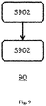
- a holding brake monitoring method comprises the following steps.
- an opening sensor corresponding to the holding brake is configured to pair two as a group to form at least two working groups, wherein the number of the opening sensor is an even number greater than 3.
- an output signal for judging the status of the holding brake is formed according to each of the working groups.
- the opening sensor in the context of the present application refers to a sensor that can detect the opening status of the holding brake, and it can judge whether the holding brake is operating according to the detection situation. For example, when the holding brake is in a slack status, its opening is larger; when the holding brake is operating, its opening is smaller.
- the opening sensor in some examples of the present application does not detect the specific value of the opening, and it can judge whether the holding brake is in an operating status according to a set threshold (for example, by configuring different gaps).
- the opening sensor in some examples of the present application may be implemented with a micro switch or the like.
- the number of opening sensors is usually set to an even number and greater than 3. Therefore, for the case of less than 3, there is no need to address in a group manner described below.
- These even number of opening sensors are configured to pair two as a group, and generate output signals for judging the status of the holding brake in units of groups.
- These paired groups are also referred to as "working groups" in the context of the present application.
- the output signal can be sent to, for example, the judgment circuit 11 in FIG. 1 , and the judgment circuit 11 specifically judges the status of the holding brake.
- the judgment circuit 11 may not necessarily judge the status of each holding brake, but judge the status of the holding brake group, and thereby infer the status of the holding brake system.
- this grouping method can significantly reduce the port occupation of the judgment circuit 11, for example, to about one-half of the original required number of ports.
- step S902 if the number of the holding brake is an odd number, one of the holding brakes is configured to be coupled to two corresponding opening sensors and the two corresponding opening sensor is paired into a working group, and each of the remaining holding brakes is configured to be coupled to a corresponding opening sensor.
- step S902 if the number of the holding brakes is an even number, each of the holding brakes is configured to be coupled to a corresponding opening sensor.
Landscapes
- Engineering & Computer Science (AREA)
- General Engineering & Computer Science (AREA)
- Physics & Mathematics (AREA)
- General Physics & Mathematics (AREA)
- Mechanical Engineering (AREA)
- Maintenance And Inspection Apparatuses For Elevators (AREA)
- Valves And Accessory Devices For Braking Systems (AREA)
Abstract
Description
- The present application relates to the field of elevators, and specifically to a holding brake monitoring circuit system, an elevator system, and a holding brake monitoring method.
- In the elevator field, the holding brake monitoring circuit system is an effective method to monitor whether the holding brake of the elevator works normally. The existing monitoring circuit collects the opening and closing status of each micro switch corresponding to the holding brake, and judges whether each holding brake is working normally based on this, and then judges whether the holding brake system comprising multiple holding brakes is working normally.
- However, this method usually needs to scan the output signal of each micro switch, which is sometimes inefficient. In addition, since the output of each micro switch is introduced into the judgment circuit, this will also occupy a large number of ports of the judgment circuit. In some cases, the number of ports may limit the number of micro switches that can be configured.
- In order to at least solve the inefficiency problem of the need to scan the output signal of each micro switch, embodiments of the present application provide a holding brake monitoring circuit system, an elevator system, and a holding brake monitoring method, which can monitor working status of the holding brake of the elevator in a group manner to improve the efficiency of monitoring.
- According to an aspect of the present application, there is provided a holding brake monitoring circuit system comprising: a plurality of opening sensors corresponding to holding brakes, wherein the number of the opening sensors is an even number greater than 3, and the opening sensors are configured to be paired to form at least two working groups, and each of the working groups is configured to output an output signal for judging status of the holding brake(s).
- In some embodiments of the present application, optionally, if the number of the holding brake is an odd number, one of the holding brakes is configured to be coupled to two of the opening sensors which are paired into a working group, and each of the remaining holding brakes is configured to be coupled to respective one of the opening sensors.
- In some embodiments of the present application, optionally, if the number of the holding brakes is an even number, each of the holding brakes is configured to be coupled to respective one of the opening sensors.
- In some embodiments of the present application, optionally, each of the opening sensors has a basic polarity, a normally closed polarity, and an operation polarity; for each of the opening sensors being not in operation, its basic polarity is turned on and its normally closed polarity or operation polarity is turned on; and for each of the opening sensors being in normal operation, its basic polarity is turned on and its operation polarity or normally closed polarity is turned on.
- In some embodiments of the present application, optionally, each of the working groups is connected in series.
- In some embodiments of the present application, optionally, the basic polarities of the two opening sensors in each of the working group are connected; when being connected in series, the normally closed polarity of the first opening sensor of the first working group is connected to the high potential, and the operation polarity of the second opening sensor is also connected to the high potential, the normally closed polarity of the second opening sensor is for the next working group to be connected; and the first part of the output signal is generated based on the operation polarity of the first opening sensor of the first working group.
- In some embodiments of the present application, optionally, in the serial connection, except for the first working group, the normally closed polarity of the first opening sensor of each of the working groups is connected to the previous working group, and the operation polarity of the second opening sensor is connected to the high potential; and the second part of the output signal is generated based on the operation polarity of the first opening sensor of each of the working groups.
- In some embodiments of the present application, optionally, the third part of the output signal is generated based on the normally closed polarity of the second opening sensor of the last working group in the serial connection.
- In some embodiments of the present application, optionally, further comprising a logical AND gate configured to receive the first part and the second part of the output signal and output the fourth part of the output signal.
- In some embodiments of the present application, optionally, the holding brake monitoring circuit system further comprises a power supply device configured to provide the high potential.
- In some embodiments of the present application, optionally, the opening sensors are micro switches.
- In some embodiments of the present application, optionally, the holding brake monitoring circuit system further comprises a judgment circuit configured to determine status of the holding brakes according to the output signal.
- According to another aspect of the present application, there is provided an elevator system comprising any one of the holding brake monitoring circuit systems described above.
- According to another aspect of the present application, there is provided a holding brake monitoring method comprising: pairing a plurality of opening sensors corresponding to holding brakes to form at least two working groups, wherein the number of the opening sensors is an even number greater than 3; and forming an output signal for judging status of the holding brakes according to each of the working groups.
- In some embodiments of the present application, optionally, the step of pairing the opening sensors comprises: if the number of the holding brakes is an odd number, one of the holding brakes is configured to be coupled to two of the opening sensors which are paired into a working group, and each of the remaining holding brakes is configured to be coupled to respective one of the opening sensors.
- In some embodiments of the present application, optionally, the step of pairing the opening sensors comprises: if the number of the holding brakes is an even number, each of the holding brakes is configured to be coupled to respective one of the opening sensors.
- The holding brake monitoring circuit system and the elevator system comprising the holding brake monitoring circuit system according to some aspects of the present application can monitor working status of the holding brake of the elevator in a group manner, thereby overcoming the inefficiency problem of the need to scan the output signal of each micro switch. In addition, the requirements for the number of ports of the processing circuit board can also be reduced.
- From the following detailed description in conjunction with the accompanying drawings, the above and other objectives and advantages of the present application will be more complete and clear, wherein the same or similar elements are represented by the same reference numerals. The figure shows the groups described in detail below in the form of a dashed frame. This division is logical and embodied in the circuit connection structure. The physical characteristics such as the position of the opening sensor comprised in the groups are not affected by this division.
-
FIG. 1 shows the working principle of a holding brake monitoring circuit system according to the prior art. -
FIG. 2 schematically shows a holding brake monitoring circuit system according to an embodiment of the present application. -
FIG. 3 schematically shows a holding brake monitoring circuit system according to another embodiment of the present application. -
FIG. 4 schematically shows a holding brake monitoring circuit system according to another embodiment of the present application. -
FIG. 5 schematically shows a holding brake monitoring circuit system according to another embodiment of the present application. -
FIG. 6 schematically shows a holding brake monitoring circuit system according to another embodiment of the present application. -
FIG. 7 schematically shows a holding brake monitoring circuit system according to another embodiment of the present application. -
FIG. 8 schematically shows a holding brake monitoring circuit system according to another embodiment of the present application. -
FIG. 9 schematically shows a holding brake monitoring method according to an embodiment of the present application. - For brevity and illustrative purposes, the present application mainly refers to its exemplary embodiments to describe the principles of the present application. However, those skilled in the art will easily recognize that the same principle can be equally applied to all types of holding brake monitoring circuit systems, elevator systems, and holding brake monitoring methods, and these same or similar principles can be implemented therein, any such changes do not depart from the true spirit and scope of the present application.
- In some examples of the present application, generating an output signal based on a polarity means generating an output signal based on a level characteristic of the polarity. And the output signal may comprise multiple sources, which are described as various parts of the output signal in the present application. In some examples of the present application, the monitoring result of the holding brake monitoring circuit system may be output according to the output signal or part thereof.
-
FIG. 1 shows the principle of a holding brake monitoring circuit system according to the prior art. As shown in the figure, aholding brake system 10 comprises four holding brakes, and each of the holding brakes is coupled to a micro switch. The micro switches 101-104 can be respectively used to detect whether the corresponding brake is operating. Although four micro switches are shown in the figure, there may be more than four or less than four in the actual situation. For example, if the brake corresponding to themicro switch 102 is in a slack status, the micro switch 102 (two poles therein) is in an open status, and at the same time in a low level outward; if the brake corresponding to themicro switch 102 works, the micro switch 102 (two poles therein) is in a closed status, and at the same time in a high level outward. The output signals of the micro switches 101-104 are input to the four input ports 111-114 of ajudgment circuit 11, respectively. Thejudgment circuit 11 can judge the opening and closing status of each of the micro switches 101-104 according to the signals received by the four input ports, and judge whether each holding brake is working normally based on this, and then judge whether theholding brake system 10 is working normally. - In the case that the
holding brake system 10 does not work normally (for example, there is a holding brake that fails to operate in the holding brake system 10), thejudgment circuit 11 can issue an instruction to the elevator, and the elevator can, for example, stop at a closer floor and suspend operation according to the instruction. In addition, the information that theholding brake system 10 does not work normally can be sent to a maintenance unit through a communication network, so as to remind the maintenance unit to check and repair as soon as possible. - However, in the manner as shown in
FIG. 1 , since each micro switch corresponds to a holding brake, thejudgment circuit 11 needs to scan the output signal of each micro switch to judge the working status of theholding brake system 10. This method is sometimes inefficient, because even if a holding brake works abnormally, it needs to be repaired immediately. Under normal circumstances, the maintenance personnel do not need to know which holding brake is abnormal before arriving at the scene. In addition, since the output of each micro switch is introduced into thejudgment circuit 11, this will also occupy a large number of ports of thejudgment circuit 11, especially when there are a large number of holding brakes. Therefore, chips with a larger number of ports may be needed to implement the function of thejudgment circuit 11, thus the cost will also increase. - According to an aspect of the present application, a holding brake monitoring circuit system is provided, and the holding brake monitoring circuit system comprises an opening sensor corresponding to the holding brake. The opening sensor in the context of the present application refers to a sensor that can detect the opening status of the holding brake, and it can judge whether the holding brake is operating according to the detection situation. For example, when the holding brake is in a slack status, its opening is larger; when the holding brake is operating, its opening is smaller. The opening sensor in some examples of the present application does not detect the specific value of the opening, and it can judge whether the holding brake is in an operating status according to a set threshold (for example, by configuring different gaps). In some examples, the opening sensor in some examples of the present application may be implemented with a micro switch or the like.
- In the holding brake monitoring circuit system, the number of opening sensors is usually set to an even number and greater than 3. Therefore, for the case of less than 3, there is no need to address in a group manner described below. These even number of opening sensors are configured to pair two as a group, and generate output signals for judging the status of the holding brake in units of groups. These paired groups are also referred to as "working groups" in the context of the present application. The output signal can be sent to, for example, the
judgment circuit 11 inFIG. 1 , and thejudgment circuit 11 specifically judges the status of the holding brake. In this example, thejudgment circuit 11 may not necessarily judge the status of each holding brake, but judge the status of the holding brake group, and thereby infer the status of the holding brake system. In addition, in the case that the number of opening sensors (holding brakes) is large, this grouping method can significantly reduce the port occupation of thejudgment circuit 11, for example, to about one-half of the original required number of ports. - As shown in
FIGS. 2 and3 , there are four opening sensors in the holding brakemonitoring circuit system 20 and the holding brakemonitoring circuit system 30. Theopening sensor 201 is paired with theopening sensor 202, and theopening sensor 203 is paired with theopening sensor 204, thereby forming two groups of pairs. InFIG. 2 , theoutput signal 212 and theoutput signal 213 of the holding brakemonitoring circuit system 20 respectively correspond to the above-mentioned two groups of pairs, so that the output signal can be generated in units of groups. For example, the "single-pole double-throw" characteristics of the paired opening sensor can be used to pair two opening sensors, so that only when both of them are switched to the same status at the same time, it means that holding brakes corresponding to both of them are working normally, or the groups that both of them belong to are working normally. - The connection mode of the
opening sensor 201 and theopening sensor 202 inFIGS. 2 and3 shows a circuit connection diagram that uses the "single-pole double-throw" characteristics of the two, and the operating status of the opening sensor of this group and its corresponding holding brake can be judged from theoutput signal 212. The other groups can be connected according to the connection mode of theopening sensor 201 and theopening sensor 202. In addition, the difference between the examples corresponding toFIG. 2 andFIG. 3 will be described below. - In the example of
FIGS. 7 and8 , there are 6 opening sensors in the holding brakemonitoring circuit system 70 and the holding brakemonitoring circuit system 80. Theopening sensor 201 is paired with theopening sensor 202, theopening sensor 203 is paired with theopening sensor 204, and theopening sensor 705 is paired with theopening sensor 706, thereby forming a total of three groups of pairs InFIG. 7 , theoutput signal 212, theoutput signal 213, and theoutput signal 714 of the holding brakemonitoring circuit system 70 respectively correspond to the above-mentioned three groups of pairs, so that the output signal can be generated in units of groups. For example, the "single-pole double-throw" characteristics of the paired opening sensor can be used to pair two opening sensors, so that only when both of them are switched to the same status at the same time, it means that holding brakes corresponding to both of them are working normally, or the groups that both of them belong to are working normally. - In the examples of
FIGS. 7 and8 , the connection mode of theopening sensor 201 and theopening sensor 202 shows a circuit connection diagram that uses the "single-pole double-throw" characteristics of the two, and the operating status of the opening sensor of this group and its corresponding holding brake can be judged from theoutput signal 212. The other groups (the pair of theopening sensor 203 and theopening sensor 204, and the pair of theopening sensor 705 and the opening sensor 706) can be connected according to the connection mode of theopening sensor 201 and theopening sensor 202. In addition, the difference between the examples corresponding toFIG. 7 andFIG. 8 will be described below. - In some embodiments of the present application, if the number of holding brakes is an even number, the number of opening sensors may be equal to the number of holding brakes, and each holding brake is assigned a corresponding opening sensor. In some embodiments of the present application, the number of opening sensors may not be equal to the number of holding brakes. For example, if the number of holding brakes is an odd number, one of the holding brakes can be configured to be coupled to two (corresponding) opening sensors, and each of the remaining holding brakes can be configured to be coupled to a (corresponding) opening sensor.
- As shown in
FIGS. 4 and5 , there are 4 opening sensors in the holding brakemonitoring circuit system 40 and the holding brakemonitoring circuit system 50, and the 4 opening sensors are configured to be coupled to the 3 holding brakes (not shown). Theopening sensor 401 and theopening sensor 402 respectively correspond to a holding brake. Theopening sensor 4031 and theopening sensor 4032 jointly correspond to a holding brake. Configured in this way, even if the number of the holding brake is an odd number, the opening sensor can also be an even number, so that the pair of opening sensors can be grouped in pairs. - In some embodiments of the present application, although not necessary, the opening sensors of the holding brake
monitoring circuit system 40 inFIG. 4 and the holding brakemonitoring circuit system 50 inFIG. 5 can be paired as follows: the openingsensor 401 is paired with theopening sensor 402, and theopening sensor 4031 is paired with theopening sensor 4032, thereby forming two groups of pairs. Theoutput signal 412 and theoutput signal 413 of the holding brakemonitoring circuit system 40 respectively correspond to the above-mentioned two groups of pairs, so that the output signal can be generated in units of groups. - In some embodiments of the present application, the opening sensor specifically comprises three polarities (also referred to as "connection contacts"), i.e., basic polarity, normally closed polarity and operation polarity.
FIG. 6 shows anopening sensor 601 according to some examples of the present application. Theopening sensor 601 has ahead 6014 for sensing gap changes (caused by pressure or tension, etc.), and abasic polarity 6011, normally closedpolarity 6012 andoperation polarity 6013. The other opening sensors in the figure have the same structure as theopening sensor 601. - In some examples, when the holding brake corresponding to the
opening sensor 601 is not operating, thebasic polarity 6011 and the normally closedpolarity 6012 of theopening sensor 601 are turned on; and when the corresponding holding brake is operating normally, thebasic polarity 6011 and theoperation polarity 6013 of theopening sensor 601 are turned on. - In other examples, each opening sensor may also be configured in another manner. For example, when the holding brake corresponding to the
opening sensor 601 is not operating, thebasic polarity 6011 and theoperation polarity 6013 of theopening sensor 601 are turned on; and when the corresponding holding brake is operating normally, thebasic polarity 6011 and the normally closedpolarity 6012 of theopening sensor 601 are turned on. - The
opening sensor 601 shown inFIG. 6 may be used in corresponding examples such asFIGS. 2-5 ,7 and8 . For example, in some examples, the opening sensors shown inFIG. 6 andFIG. 2 etc. have the same configurations, and the connection mode of the opening sensor 601-604 inFIG. 6 is the physical display of the connection mode of the opening sensor 201-204 inFIG. 2 , and both have the same technical meaning. For the connection mode of each opening sensor inFIG. 6 and the principle behind it, reference may be made to the description of the corresponding example inFIG. 2 . - In some embodiments of the present application, as shown in
FIGS. 2-8 , the paired groups (each of the working groups) are connected in series, so that the characteristics of the series circuit can be used to obtain the output signal. For example, the conduction of the series circuit can be guaranteed only when each node of the series circuit is turned on. In addition, the basic polarities of the two opening sensors in each group of pairs are connected. Continuing to refer toFIG. 2 , in the serial connection, the normally closed polarity of the first opening sensor (opening sensor 201) in the first group of pairs (the first working group composed of theopening sensor 201 and the opening sensor 202) is connected to the high potential Voc, and the operation polarity of the second opening sensor (opening sensor 202) is also connected to the high potential VDC, and the normally closed polarity of the second opening sensor is provided to the next group (composed of theopening sensor 203 and the opening sensor 204). In addition, as a part of the output signal, theoutput signal 212 may also be generated based on the operation polarity of the first opening sensor of the first group. - In some embodiments of the present application, continuing to refer to
FIG. 2 , in a serial connection, except for the first group of pairs, the normally closed polarity of the first opening sensor in each paired group is connected to the previous group. For example, the normally closed polarity of the first opening sensor (opening sensor 203) in the second group of pairs (composed of theopening sensor 203 and the opening sensor 204) is connected to the normally closed polarity of the second opening sensor in the first group of pairs. On the other hand, similar to the first group, the operation polarity of the second opening sensor (opening sensor 204) in the second group of pairs is connected to the high potential VDC. In addition, as a part of the output signal, an output signal may be generated based on the operation polarity of the first opening sensor of each group. For example, it is illustrated that theoutput signal 213 is generated based on the operation polarity of the first opening sensor of the second group. - In the example of
FIG. 7 , in addition to the first group of pairs in the serial connection, the normally closed polarity of the first opening sensor in each paired group is connected to the previous group. Wherein, the normally closed polarity of the first opening sensor (opening sensor 203) in the second group of pairs (composed of theopening sensor 203 and the opening sensor 204) is connected to the normally closed polarity of the second opening sensor in the first group of pairs. On the other hand, similar to the first group, the operation polarity of the second opening sensor (opening sensor 204) in the second group of pairs is connected to the high potential VDC. In addition, as a part of the output signal, an output signal may be generated based on the operation polarity of the first opening sensor of each group. For example, it is illustrated that theoutput signal 213 is generated based on the operation polarity of the first opening sensor of the second group. - In addition, continuing to refer to
FIG. 7 , the normally closed polarity of the first opening sensor (opening sensor 705) in the third group of pairs (composed of theopening sensor 705 and the opening sensor 706) is connected to the normally closed polarity of the second opening sensor in the second group of pairs. On the other hand, similar to the first and second groups, the operation polarity of the second opening sensor (opening sensor 706) in the second group of pairs is connected to the high potential VDC. In addition, as a part of the output signal, it is illustrated that theoutput signal 714 is generated based on the operation polarity of the first opening sensor of the third group. - In some embodiments of the present application, the third part of the output signal is also generated based on the normally closed polarity of the second opening sensor of the last group of pairs (last working group) in the serial connection. Continuing to refer to
FIG. 2 , the second group is also the last group of pairs. Therefore, as a part of the output signal, theoutput signal 211 may also be generated based on the operation polarity of the second opening sensor of this group of pairs. In the example ofFIG. 7 , the third group is the last group of pairs. As a part of the output signal, theoutput signal 211 may also be generated based on the operation polarity of the second opening sensor of this group of pairs. - Taking
FIG. 2 as an example to illustrate the principles of some examples of the present application. Assuming the normal working status of the opening sensor, when the holding brake corresponding to theopening sensor 201 is not operating, the basic polarity and the normally closed polarity of theopening sensor 201 are turned on (as shown in the figure), and when the corresponding holding brake is operating normally, the basic polarity and the operation polarity of theopening sensor 201 are turned on (the switch shown by theopening sensor 201 is set to the bottom). Other opening sensors can also imitate this design. - When each of the holding brakes corresponding to the holding brake
monitoring circuit system 20 is in an inactive standby status, the opening sensors 201-204 should be in the positions shown in the figure, and theoutput signal 211 should be the same as the VDC at this time. Therefore, theoutput signal 211 can be used to judge whether each of the holding brakes corresponding to the holding brakemonitoring circuit system 20 is in a standby status when not operating, that is, each of the holding brakes should be slack. If there is any holding brake that is operating and tensioning, theoutput signal 211 will not show a level equal to VDC. It can be seen from this setting that theoutput signal 211 can be used to judge whether the initial status of the holding brakemonitoring circuit system 20 is normal. Theoutput signal 411 inFIG. 4 andFIG. 5 , and theoutput signal 211 inFIG. 7 andFIG. 8 also have the same function, which will not be repeated here. - When each of the holding brakes corresponding to the holding brake
monitoring circuit system 20 is operating, the opening sensors 201-204 should be dialed down to the other polarity. At this time, theoutput signal 211 should undergo a lower jump (for example, embodied as a falling edge), and the output signals 212 and 213 should undergo a higher jump (for example, embodied as a rising edge) and become equal to VDC. At this time, if any one of the first group of pairs fails to be dialed down to the other polarity (generally due to the failure of its corresponding holding brake), theoutput signal 212 cannot undergo the above-mentioned jump. The judgment circuit may determine, according to theoutput signal 212, that the holding brake corresponding to the group of pairs may have a fault, and may further send an instruction to stop service to the elevator control system. On the other hand, if any one of the second group of pairs fails to be dialed down to the other polarity, theoutput signal 213 cannot undergo the above-mentioned jump and cannot become equal to VDC. - Taking
FIG. 7 as an example to illustrate the working principles of some examples of the present application. Similar to the example corresponding toFig. 2 , assuming the normal working status of the opening sensor: for example, when the holding brake corresponding to theopening sensor 705 is not operating, the basic polarity and the normally closed polarity of theopening sensor 705 are turned on (as shown in the figure), and when the corresponding holding brake is operating normally, the basic polarity and the operation polarity of theopening sensor 705 are turned on (the switch shown by theopening sensor 705 is set to the bottom). Other opening sensors can also imitate this design. - When each of the holding brakes corresponding to the holding brake
monitoring circuit system 70 is in an inactive standby status, the opening sensors 201-204, 705 and 706 should be in the positions shown in the figure, and theoutput signal 211 should be the same as the VDC at this time. Therefore, theoutput signal 211 can be used to judge whether each of the holding brakes corresponding to the holding brakemonitoring circuit system 70 is in a standby status when not operating, that is, each of the holding brakes should be slack. If there is any holding brake that is operating and tensioning, theoutput signal 211 will not show a level equal to VDC. It can be seen from this setting that theoutput signal 211 can be used to judge whether the initial status of the holding brakemonitoring circuit system 70 is normal. - When each of the holding brakes corresponding to the holding brake
monitoring circuit system 70 is operating, the opening sensors 201-204, 705 and 706 should be dialed down to the other polarity. At this time, theoutput signal 211 should undergo a lower jump (for example, embodied as a falling edge), and the output signals 212, 213 and 714 should undergo a higher jump (for example, embodied as a rising edge) and become equal to VDC. At this time, if any one of the third group of pairs fails to be dialed down to the other polarity (generally due to the failure of its corresponding holding brake), theoutput signal 714 cannot undergo the above-mentioned jump. The judgment circuit may determine, according to theoutput signal 714, that the holding brake corresponding to the group of pairs may have a fault, and may further send an instruction to stop service to the elevator control system. On the other hand, if any one of the other groups of pairs fails to be dialed down to the other polarity, its corresponding output signal cannot undergo the above-mentioned jump and cannot become equal to VDC. - In some embodiments of the present application, as shown in
FIGS. 3 and5 , the holding brake monitoring circuit system 30 (50) further comprises a logical AND gate 32 (52). Wherein, the input of the logic ANDgate 32 comprises: the first part (analogous to theoutput signal 212 inFIG. 2 ) and the second part (analogous to theoutput signal 213 inFIG. 2 ) of the output signal, and the output of the logic ANDgate 32 can be the fourth part of the output signal, for example, theoutput signal 312 shown inFIG. 3 . The logic ANDgate 52 inFIG. 5 is also configured according to the configuration of the logic ANDgate 32, and the output of the holding brakemonitoring circuit system 50 comprises asignal 512. In the example ofFIG. 8 , the holding brakemonitoring circuit system 80 further comprises a logical ANDgate 82. Wherein, the input of the logical ANDgate 82 comprises: the output signal of the first group (analogous to theoutput signal 212 inFIG. 7 ), the output signal of the second group (analogous to theoutput signal 213 inFIG. 7 ), and the output signal of the third group (analogous to theoutput signal 714 inFIG. 7 ), and the output of the logical ANDgate 32 can be the fourth part of the output signal, for example, theoutput signal 812 shown inFIG.8 . - Continuing the above example, after introducing the logic AND
gate 32 inFIG. 3 , if any one of thecorresponding output signal 212 or theoutput signal 213 inFIG. 2 fails to undergo the above-mentioned jump, it becomes equal to VDC, theoutput signal 312 will not undergo a higher jump (for example, it becomes equal to VDC). Similarly, after introducing the logic ANDgate 82 inFIG. 8 , if any one of the corresponding output signals 212, 213, and 714 inFig. 7 fails to undergo the above-mentioned jump and cannot becomes equal to VDC, then theoutput signal 812 will not undergo a higher jump (for example, it becomes equal to VDC). Theabove output signals - The above also introduces that each opening sensor can be configured in another way. Wherein, when the holding brake corresponding to the opening sensor is not operating, the basic polarity and the operation polarity of the opening sensor are turned on, and when the corresponding holding brake is operating normally, the basic polarity and the normally closed polarity of the opening sensor are turned on.
- For example, continuing to refer to the example of
FIG. 2 , when each of the holding brakes corresponding to the holding brakemonitoring circuit system 20 is in an inactive standby status, the opening sensors 201-204 should be in the opposite position shown in the figure (dial to the lower contact in the figure). At this time, the output signals 212 and 213 should be the same as VDC. Therefore, the output signals 212 and 213 can be used to judge whether each of the holding brakes corresponding to the holding brakemonitoring circuit system 20 is in a standby status when not operating, that is, each of the holding brakes should be slack. If there is any holding brake in the first group that is operating and tensioning, theoutput signal 212 will not show a level equal to VDC; if there is any holding brake in the second group that is operating and tensioning, theoutput signal 213 will not show a level equal to VDC. It can be seen from this setting that the output signals 212 and 213 can be used to judge whether the initial status of the holding brakemonitoring circuit system 20 is normal. - Continuing the above example, when the logic AND
gate 32 is introduced inFIG. 3 , if any one of thecorresponding output signal 212 or theoutput signal 213 inFIG. 2 is not equal to VDC, theoutput signal 312 will not reflected as a high level. Therefore, theoutput signal 312 can also be used to judge whether the initial status of the holdingbrake system 30 is normal. - Continuing to refer to
FIG. 2 , when each of the holding brakes corresponding to the holding brakemonitoring circuit system 20 is operating, the opening sensors 201-204 should be switched to the position shown in the figure, at this time, theoutput signal 211 should undergo a higher jump (for example, embodied as a rising edge), if any opening sensor of the any group fails to be dialed down to the other polarity (generally due to the failure of its corresponding holding brake), theoutput signal 211 cannot undergo the above-mentioned jump. The judgment circuit may determine, according to theoutput signal 211, that the holding brake system may have a fault, and may further send an instruction to stop service to the elevator control system. - The basic principles described above with respect to
FIG. 2 andFIG. 3 are equally applicable to the corresponding examples ofFIG. 4 andFIG. 5 ,FIG. 7 andFIG. 8 , and will not be repeated here. - According to another aspect of the present application, an elevator system is provided. The elevator system comprises any holding brake monitoring circuit system as described above. According to the above description of the holding brake monitoring circuit system, once the holding brake is found to be faulty, the elevator can be configured to stop running, for example, so as to reduce the probability of running accidents.
- According to another aspect of the present application, a holding brake monitoring method is provided. As shown in
FIG. 9 , the holdingbrake monitoring method 90 comprises the following steps. In step S902, an opening sensor corresponding to the holding brake is configured to pair two as a group to form at least two working groups, wherein the number of the opening sensor is an even number greater than 3. In step S904, an output signal for judging the status of the holding brake is formed according to each of the working groups. - The opening sensor in the context of the present application refers to a sensor that can detect the opening status of the holding brake, and it can judge whether the holding brake is operating according to the detection situation. For example, when the holding brake is in a slack status, its opening is larger; when the holding brake is operating, its opening is smaller. The opening sensor in some examples of the present application does not detect the specific value of the opening, and it can judge whether the holding brake is in an operating status according to a set threshold (for example, by configuring different gaps). In some examples, the opening sensor in some examples of the present application may be implemented with a micro switch or the like.
- In the holding brake monitoring circuit system, the number of opening sensors is usually set to an even number and greater than 3. Therefore, for the case of less than 3, there is no need to address in a group manner described below. These even number of opening sensors are configured to pair two as a group, and generate output signals for judging the status of the holding brake in units of groups. These paired groups are also referred to as "working groups" in the context of the present application. The output signal can be sent to, for example, the
judgment circuit 11 inFIG. 1 , and thejudgment circuit 11 specifically judges the status of the holding brake. In this example, thejudgment circuit 11 may not necessarily judge the status of each holding brake, but judge the status of the holding brake group, and thereby infer the status of the holding brake system. In addition, in the case that the number of opening sensors (holding brakes) is large, this grouping method can significantly reduce the port occupation of thejudgment circuit 11, for example, to about one-half of the original required number of ports. - In some embodiments of the present application, the following process is specifically executed in step S902: if the number of the holding brake is an odd number, one of the holding brakes is configured to be coupled to two corresponding opening sensors and the two corresponding opening sensor is paired into a working group, and each of the remaining holding brakes is configured to be coupled to a corresponding opening sensor.
- In some embodiments of the present application, the following process is specifically executed in step S902: if the number of the holding brakes is an even number, each of the holding brakes is configured to be coupled to a corresponding opening sensor.
- It should be understood that the relative position terms recorded in the present application (such as "forward", "backward", "upper", "lower", "above", "below", "bottom", "top" ", etc.) refer to normal operating postures and should not be considered as being restricted in other ways. It should be understood that the same reference numbers throughout the multiple figures identify corresponding or similar elements. It should also be understood that although specific component configurations are disclosed in the illustrated embodiment, other configurations will benefit from this.
- Although different non-limiting embodiments have specifically illustrated components, the embodiments of the present application are not limited to these specific combinations. It is possible to use components or some of the features from any non-limiting embodiment in combination with features or components from any other non-limiting embodiment. The above are only specific implementations of the present application, but the protection scope of the present application is not limited thereto. Those skilled in the art can think of other feasible changes or substitutions according to the technical scope disclosed in the present application, and these changes or substitutions are all covered by the protection scope of the present application. In the case of no conflict, the embodiments of the present application and the features in the embodiments can also be combined with each other. The protection scope of the present application is subject to the description of the claims.
Claims (15)
- A holding brake monitoring circuit system comprising: a plurality of opening sensors corresponding to holding brakes, wherein the number of the opening sensors is an even number greater than 3, and the opening sensors are configured to be paired to form at least two working groups, and each of the working groups is configured to output an output signal for judging status of its corresponding holding brake(s).
- The holding brake monitoring circuit system according to claim 1, wherein if the number of the holding brakes is an odd number, one of the holding brakes is configured to be coupled to two of the opening sensors which are paired into a working group, and each of the remaining holding brakes is configured to be coupled to a respective one of the opening sensors.
- The holding brake monitoring circuit system according to any preceding claim, wherein if the number of the holding brakes is an even number, each of the holding brakes is configured to be coupled to a respective one of the opening sensors.
- The holding brake monitoring circuit system according to any preceding claim, wherein each of the opening sensors has a basic polarity, a normally closed polarity, and an operation polarity;for each of the opening sensors being not in operation, its basic polarity is turned on and its normally closed polarity or operation polarity is turned on; andfor each of the opening sensors being in normal operation, its basic polarity is turned on and its operation polarity or normally closed polarity is turned on.
- The holding brake monitoring circuit system according to any preceding claim, wherein the working groups are connected in series.
- The holding brake monitoring circuit system according to claim 5, wherein the basic polarities of the two opening sensors in each of the working group are connected;when being connected in series, the normally closed polarity of the first opening sensor of the first working group is connected to the high potential, and the operation polarity of the second opening sensor is also connected to the high potential, the normally closed polarity of the second opening sensor is for the next working group to be connected; andthe first part of the output signal is generated based on the operation polarity of the first opening sensor of the first working group.
- The holding brake monitoring circuit system according to claim 5 or 6, wherein, in the serial connection, except for the first working group, the normally closed polarity of the first opening sensor of each of the working groups is connected to the previous working group, and the operation polarity of the second opening sensor is connected to the high potential; and
the second part of the output signal is generated based on the operation polarity of the first opening sensor of each of the working groups. - The holding brake monitoring circuit system according to any of claims 5 to 7, wherein, the third part of the output signal is generated based on the normally closed polarity of the second opening sensor of the last working group in the serial connection.
- The holding brake monitoring circuit system according to any of claims 5 to 8, further comprising a logical AND gate configured to receive the first part and the second part of the output signal and output the fourth part of the output signal.
- The holding brake monitoring circuit system according to any of claims 6 to 9, further comprising a power supply device configured to provide the high potential.
- The holding brake monitoring circuit system according to any preceding claim, wherein the opening sensors are micro switches.
- The holding brake monitoring circuit system according to any preceding claim, further comprising a judgment circuit configured to determine status of the holding brakes according to the output signal.
- An elevator system, comprising the holding brake monitoring circuit system according to any one of claims 1-12.
- A holding brake monitoring method, comprising:pairing a plurality of opening sensors corresponding to holding brakes to form at least two working groups, wherein the number of the opening sensors is an even number greater than 3; andforming an output signal for judging status of the holding brakes according to each of the working groups.
- The holding brake monitoring method according to claim 14, wherein the step of pairing the opening sensors comprises: if the number of the holding brakes is an odd number, one of the holding brakes is configured to be coupled to two of the opening sensors which are paired into a working group, and each of the remaining holding brakes is configured to be coupled to respective one of the opening sensors;
and/or
wherein the step of pairing the opening sensors comprises: if the number of the holding brakes is an even number, each of the holding brakes is configured to be coupled to respective one of the opening sensors.
Applications Claiming Priority (1)
| Application Number | Priority Date | Filing Date | Title |
|---|---|---|---|
| CN202110591473.3A CN115402895A (en) | 2021-05-28 | 2021-05-28 | Band-type brake monitoring circuit system, elevator system and band-type brake monitoring method |
Publications (1)
| Publication Number | Publication Date |
|---|---|
| EP4095080A1 true EP4095080A1 (en) | 2022-11-30 |
Family
ID=78828127
Family Applications (1)
| Application Number | Title | Priority Date | Filing Date |
|---|---|---|---|
| EP21213529.7A Withdrawn EP4095080A1 (en) | 2021-05-28 | 2021-12-09 | Holding brake monitoring circuit system, elevator system and holding brake monitoring method |
Country Status (3)
| Country | Link |
|---|---|
| US (1) | US11787660B2 (en) |
| EP (1) | EP4095080A1 (en) |
| CN (1) | CN115402895A (en) |
Citations (3)
| Publication number | Priority date | Publication date | Assignee | Title |
|---|---|---|---|---|
| EP2457861A1 (en) * | 2009-07-21 | 2012-05-30 | Mitsubishi Electric Corporation | Control device for elevator |
| CN105565100A (en) * | 2016-02-05 | 2016-05-11 | 溧阳市天目湖中等专业学校 | Elevator safety real-time monitoring control system and control method thereof |
| EP3351499A1 (en) * | 2017-01-24 | 2018-07-25 | Otis Elevator Company | Elevator system |
Family Cites Families (30)
| Publication number | Priority date | Publication date | Assignee | Title |
|---|---|---|---|---|
| US3134061A (en) | 1959-06-30 | 1964-05-19 | Jacob A Nederbragt | Control of elevator motors |
| US3895692A (en) * | 1967-02-07 | 1975-07-22 | Reliance Electric & Eng Co | Elevator control |
| JPH04101976A (en) | 1990-08-21 | 1992-04-03 | Hitachi Building Syst Eng & Service Co Ltd | Inching operating device for elevator |
| WO2000007256A1 (en) * | 1998-07-27 | 2000-02-10 | Gnb Technologies | Apparatus and method for carrying out diagnostic tests on batteries and for rapidly charging batteries |
| JP4613027B2 (en) * | 2003-04-14 | 2011-01-12 | インベンテイオ・アクテイエンゲゼルシヤフト | Drive device with linear motor, elevator with drive device, and method of operating the drive device |
| FI118642B (en) * | 2006-04-28 | 2008-01-31 | Kone Corp | Elevator system |
| FI119767B (en) | 2006-08-14 | 2009-03-13 | Kone Corp | Elevator systems and procedures that ensure the safety of an elevator system |
| US9441692B2 (en) * | 2008-03-11 | 2016-09-13 | Honeywell International Inc. | Proximity sensor for brake wear detection |
| WO2011146076A1 (en) * | 2010-05-21 | 2011-11-24 | Otis Elevator Company | Brake for elevator |
| FI20115145A7 (en) * | 2011-02-15 | 2012-08-16 | Kone Corp | Mounting interface for machine brake and machine brake |
| CN202245602U (en) | 2011-08-30 | 2012-05-30 | 昆山通祐电梯有限公司 | Self-rescue device for elevator |
| CN202296644U (en) | 2011-09-30 | 2012-07-04 | 快意电梯有限公司 | Device for preventing accidental movement of elevator cage |
| JP6117633B2 (en) * | 2013-06-25 | 2017-04-19 | 株式会社日立ビルシステム | Brake mechanism inspection device for elevators |
| CN203529643U (en) | 2013-09-05 | 2014-04-09 | 申芝电梯有限公司 | Elevator self-help protection device |
| WO2015058913A1 (en) | 2013-10-23 | 2015-04-30 | Inventio Ag | Method and apparatus for commissioning a lift installation |
| CN105793187B (en) * | 2013-12-09 | 2018-02-13 | 因温特奥股份公司 | The brake force monitor of elevator brake |
| CN104058309B (en) | 2014-06-23 | 2016-05-04 | 重庆市特种设备检测研究院 | A kind of electric safety return circuit of elevator redundancy and stop control method |
| CN204096806U (en) | 2014-09-10 | 2015-01-14 | 山东大汉建设机械有限公司 | A kind of building hoist brake equipment monitoring system |
| CN104291197B (en) | 2014-09-28 | 2016-01-20 | 重庆伊士顿电梯有限责任公司 | Knapsack elevator switch accelerator control system and method |
| CN104555626B (en) | 2015-01-09 | 2016-08-24 | 中联重科股份有限公司 | Control method for safe descent of construction hoist due to power failure |
| CN105236232B (en) | 2015-11-17 | 2018-05-18 | 大连市特种设备检测研究院 | Building hoist remote electric declutches emergency rescue apparatus and its method of work |
| CN205652937U (en) | 2016-04-06 | 2016-10-19 | 巨立电梯股份有限公司 | Elevator circuit |
| CN106586737B (en) | 2016-11-24 | 2019-07-26 | 江苏旭云物联信息科技有限公司 | A kind of intelligent elevator control system |
| CN106882662B (en) | 2017-01-13 | 2019-09-24 | 广州广日电梯工业有限公司 | A kind of elevator rescue system |
| CN207390701U (en) | 2017-06-29 | 2018-05-22 | 快意电梯股份有限公司 | Safety-type elevator inspection control device |
| CN108439117B (en) | 2018-02-23 | 2020-02-14 | 上海广为美线电源电器有限公司 | Elevator brake release device |
| CN112638817B (en) * | 2018-08-22 | 2023-04-04 | 通力股份公司 | Elevator brake apparatus |
| CN209543739U (en) | 2018-12-05 | 2019-10-25 | 苏州市职业大学 | An elevator brake training device |
| CN111532920B (en) | 2020-05-07 | 2022-07-19 | 永大电梯设备(中国)有限公司 | A protection system for elevator maintenance personnel and elevator |
| CN111807182B (en) | 2020-07-17 | 2021-08-10 | 安徽迅立达电梯有限公司 | Operation method convenient for safe installation of elevator |
-
2021
- 2021-05-28 CN CN202110591473.3A patent/CN115402895A/en active Pending
- 2021-11-30 US US17/537,587 patent/US11787660B2/en active Active
- 2021-12-09 EP EP21213529.7A patent/EP4095080A1/en not_active Withdrawn
Patent Citations (3)
| Publication number | Priority date | Publication date | Assignee | Title |
|---|---|---|---|---|
| EP2457861A1 (en) * | 2009-07-21 | 2012-05-30 | Mitsubishi Electric Corporation | Control device for elevator |
| CN105565100A (en) * | 2016-02-05 | 2016-05-11 | 溧阳市天目湖中等专业学校 | Elevator safety real-time monitoring control system and control method thereof |
| EP3351499A1 (en) * | 2017-01-24 | 2018-07-25 | Otis Elevator Company | Elevator system |
Also Published As
| Publication number | Publication date |
|---|---|
| US11787660B2 (en) | 2023-10-17 |
| CN115402895A (en) | 2022-11-29 |
| US20220380174A1 (en) | 2022-12-01 |
Similar Documents
| Publication | Publication Date | Title |
|---|---|---|
| JP3321556B2 (en) | Degeneration control method, multiplexing control device | |
| EP2464040B1 (en) | Protection device and protection method for optical network | |
| CN104101831A (en) | Relay failure detection system | |
| WO2001033897A3 (en) | An optical cross-connect switching system with bridging, test access and redundancy | |
| US11787660B2 (en) | Brake monitoring circuitry, elevator system and brake monitoring method | |
| US11169491B2 (en) | Safety switch | |
| WO2015184737A1 (en) | Power supply processing method and device, and power source | |
| US20220219943A1 (en) | Voltage signal processing unit, landing door failure locating system and method, elevator system | |
| US6769072B1 (en) | Distributed processing system with registered reconfiguration processors and registered notified processors | |
| US20120176706A1 (en) | Reliable signaling of fault conditions in battery systems with series-connected cells | |
| CN112255524A (en) | Protection method and detection device for electric transmission traction system | |
| US7836208B2 (en) | Dedicated redundant links in a communicaton system | |
| US9397763B2 (en) | Method for detecting abnormality of input signal and slave station for use in same | |
| KR20050095071A (en) | A system for controlling railway line | |
| JPH06132920A (en) | Switching circuit of transmission device having redundant configuration | |
| JP2715899B2 (en) | Timing source switching control method | |
| SU1238264A1 (en) | Device for checking control circuit of matrix connectors | |
| CN1734271A (en) | TPS protection plate detection method | |
| KR0157950B1 (en) | Control method of signal electrical transmission for an elevator | |
| JPS63282074A (en) | Signal transmitter for elevator | |
| JPS6178243A (en) | Faulty station detecting system in duplicated loop network | |
| KR980013214A (en) | In the TMR (TMR) structure, | |
| JPH09239600A (en) | Noncontact controller for press | |
| KR19990026348A (en) | Remote monitoring method of elevator | |
| JPH08331246A (en) | Centralized monitoring system |
Legal Events
| Date | Code | Title | Description |
|---|---|---|---|
| PUAI | Public reference made under article 153(3) epc to a published international application that has entered the european phase |
Free format text: ORIGINAL CODE: 0009012 |
|
| STAA | Information on the status of an ep patent application or granted ep patent |
Free format text: STATUS: THE APPLICATION HAS BEEN PUBLISHED |
|
| AK | Designated contracting states |
Kind code of ref document: A1 Designated state(s): AL AT BE BG CH CY CZ DE DK EE ES FI FR GB GR HR HU IE IS IT LI LT LU LV MC MK MT NL NO PL PT RO RS SE SI SK SM TR |
|
| STAA | Information on the status of an ep patent application or granted ep patent |
Free format text: STATUS: REQUEST FOR EXAMINATION WAS MADE |
|
| 17P | Request for examination filed |
Effective date: 20230526 |
|
| RBV | Designated contracting states (corrected) |
Designated state(s): AL AT BE BG CH CY CZ DE DK EE ES FI FR GB GR HR HU IE IS IT LI LT LU LV MC MK MT NL NO PL PT RO RS SE SI SK SM TR |
|
| STAA | Information on the status of an ep patent application or granted ep patent |
Free format text: STATUS: EXAMINATION IS IN PROGRESS |
|
| 17Q | First examination report despatched |
Effective date: 20240410 |
|
| STAA | Information on the status of an ep patent application or granted ep patent |
Free format text: STATUS: THE APPLICATION HAS BEEN WITHDRAWN |
|
| 18W | Application withdrawn |
Effective date: 20240716 |