EP4095041A1 - Pneumatic de-icer with reduced non-inflatable area at deicer edge - Google Patents
Pneumatic de-icer with reduced non-inflatable area at deicer edge Download PDFInfo
- Publication number
- EP4095041A1 EP4095041A1 EP22175933.5A EP22175933A EP4095041A1 EP 4095041 A1 EP4095041 A1 EP 4095041A1 EP 22175933 A EP22175933 A EP 22175933A EP 4095041 A1 EP4095041 A1 EP 4095041A1
- Authority
- EP
- European Patent Office
- Prior art keywords
- inflatable
- edge
- icer
- tubes
- centerline
- Prior art date
- Legal status (The legal status is an assumption and is not a legal conclusion. Google has not performed a legal analysis and makes no representation as to the accuracy of the status listed.)
- Granted
Links
Images


Classifications
-
- B—PERFORMING OPERATIONS; TRANSPORTING
- B64—AIRCRAFT; AVIATION; COSMONAUTICS
- B64D—EQUIPMENT FOR FITTING IN OR TO AIRCRAFT; FLIGHT SUITS; PARACHUTES; ARRANGEMENT OR MOUNTING OF POWER PLANTS OR PROPULSION TRANSMISSIONS IN AIRCRAFT
- B64D15/00—De-icing or preventing icing on exterior surfaces of aircraft
- B64D15/16—De-icing or preventing icing on exterior surfaces of aircraft by mechanical means, e.g. pulsating mats or shoes attached to, or built into, surface
- B64D15/166—De-icing or preventing icing on exterior surfaces of aircraft by mechanical means, e.g. pulsating mats or shoes attached to, or built into, surface using pneumatic boots
Definitions
- a de-icer includes first and second structural layers that each include centerline and a non-inflatable edge angled with respect to the centerline, edge sealing material disposed to adhere the first and second structural layers together to form a non-inflatable edge area extending along at least the non-inflatable edge and surrounding a central area and stitching.
- the stitching is disposed to stitch the first and second structural layers together in the central area to form tubes.
- the tubes include an outermost tube which is closest to and parallel with the non-inflatable edge.
- the first and second structural layers each have a trapezoidal shape with the non-inflatable edge and an additional non-inflatable edge on opposite sides of the centerline.
- the de-icer remains adhered to the aerodynamic surface during inflation and deflation of the tubes.
- the stitching has a same pattern for each of the tubes and the outermost tube.
- the de-icer remains adhered to the aerodynamic surface during inflation and deflation of the tubes.
- This uniform loading permits the non-inflatable area 150 extending along the tapered or non-inflatable edges 115 and 125 and the additional tapered or non-inflatable edges 116 and 126 to be reduced in width when the parallel edge outermost tube 161 1 and additional outermost tube 161 2 are provided as compared to conventional instances of de-icers.
Landscapes
- Engineering & Computer Science (AREA)
- Mechanical Engineering (AREA)
- Aviation & Aerospace Engineering (AREA)
- Laminated Bodies (AREA)
- Air Bags (AREA)
- Tents Or Canopies (AREA)
Abstract
Description
- The present disclosure relates to de-icers and, more particularly, to a pneumatic de-icer with a reduced non-inflatable area at a de-icer edge.
- In certain aircraft applications, pneumatic de-icers are used to control the build-up of ice on aerodynamic surfaces. The de-icers are thin elastomeric blankets containing an array of fabric-reinforced tubes which inflate periodically to fracture and shed accreted ice. For example, for some turboprop airplanes, de-icers are provided on leading edges of wings and empennage to control the build-up of ice on those leading edges. In these or other cases, the de-icers can operate in one or more manners. In a first manner, the de-icer is commanded by the pilot to inflate and deflate once in order to break up ice. The ice, once fractured, naturally is removed from the surface where the de-icer is deployed by the scavenging effects of the airstream. In a second manner, the de-icer is periodically commanded by a timer on a repeating basis to inflate and deflate in order to break up and remove the ice.
- In conventional instances, de-icers are applied and adhered to a surface and include multiple layers that are adhered and sown together. Typically, the perimeter area, which can be referred to as the "non-inflatable area," is adhered together, and the interior area, which can be referred to as the "carcass" or "inflatable area" is sewn to form multiple tubes along a longitudinal length of the de-icer. The non-inflatable area is often provided with a tapered cross section but also may have a uniform thickness along the edge of the de-icer and the tubes are often parallel with one another. This arrangement results in some situations where the non-inflatable area crosses the outermost tubes at an angle and, in so doing, leads to the borders of those outermost tubes having non-uniform loading on the non-inflatable area and variable and potentially unreliable adhesion to the airfoil surface. As a result, the width of the non-inflatable area has to be made relatively large in order to insure that the non-inflatable area can provide a reliable bond to the airfoil for the outermost tubes.
- The relatively large width of the non-inflatable area in conventional instances of de-icers leads to either corresponding reduction in the relative sizes of the tubes or reduced operating capabilities when the overall size of the de-icer is limited such as in a recess in the airfoil surface for de-icer installation. In addition, even with the relatively large width, the non-inflatable areas may not provide a reliable bond to the airfoil surface.
- Accordingly, a need exists for a de-icer with a non-inflatable area that has a reduced non-inflatable edge width and increased reliability.
- According to an aspect of the disclosure, a de-icer is provided and includes first and second structural layers that each include centerline and a non-inflatable edge angled with respect to the centerline, edge sealing material disposed to adhere the first and second structural layers together to form a non-inflatable edge area extending along at least the non-inflatable edge and surrounding a central area and stitching. The stitching is disposed to stitch the first and second structural layers together in the central area to form tubes. The tubes include an outermost tube which is closest to and parallel with the non-inflatable edge.
- In accordance with additional or alternative embodiments, the first and second structural layers each have a trapezoidal shape with the non-inflatable edge and an additional non-inflatable edge on opposite sides of the centerline.
- In accordance with additional or alternative embodiments, the tubes include multiple central tubes which are parallel with the centerline, the outermost tube and an additional outermost tube which is closest to and parallel with the additional non-inflatable edge.
- In accordance with additional or alternative embodiments, the stitching has a same pattern for each of the tubes and the outermost tube.
- In accordance with additional or alternative embodiments, the non-inflatable edge area is about ~0.5 to about ~0.9375 inches (~1.27 to about ~2.38125 cm) wide.
- In accordance with additional or alternative embodiments, the non-inflatable edge area is about ~0.75 to about ~0.875 inches (~1.905 to about ~2.2225 cm) wide.
- In accordance with additional or alternative embodiments, the outermost tube is narrower than at least one of the other tubes.
- According to an aspect of the disclosure, an aircraft is provided and includes an aerodynamic surface and a de-icer operably disposed on the aerodynamic surface.
- In accordance with additional or alternative embodiments, the de-icer remains adhered to the aerodynamic surface during inflation and deflation of the tubes.
- According to an aspect of the disclosure, a de-icer is provided and includes first and second structural layers, edge sealing material and stitching. The first and second structural layers each include wide and narrow ends, a centerline extending between the wide and narrow ends and a non-inflatable edge which extends between the wide and narrow ends and is angled with respect to the centerline. The edge sealing material is disposed to adhere the first and second structural layers together to form a non-inflatable edge area extending along at least the non-inflatable edge and surrounding a central area. The stitching is disposed to stitch the first and second structural layers together in the central area to form tubes. The tubes are inflatable and de-inflatable for de-icing operations and include an outermost tube which is closest to and parallel with the non-inflatable edge.
- In accordance with additional or alternative embodiments, the first and second structural layers each have a trapezoidal shape with the non-inflatable edge and an additional non-inflatable edge on opposite sides of the centerline.
- In accordance with additional or alternative embodiments, the tubes include multiple central tubes which are parallel with the centerline, the outermost tube and an additional outermost tube which is closest to and parallel with the additional non-inflatable edge.
- In accordance with additional or alternative embodiments, the non-inflatable edge area extends along the wide and narrow ends, the non-inflatable edge and the additional non-inflatable edge.
- In accordance with additional or alternative embodiments, the stitching has a same pattern for each of the tubes and the outermost tube.
- In accordance with additional or alternative embodiments, the non-inflatable edge area is about ~0.5 to about ~0.9375 inches (~1.27 to about ~2.38125 cm) wide.
- In accordance with additional or alternative embodiments, the non-inflatable edge area is about ~0.75 to about ~0.875 inches (~1.905 to about ~2.2225 cm) wide.
- In accordance with additional or alternative embodiments, the outermost tube is narrower than at least one of the other tubes.
- According to an aspect of the disclosure, an aircraft is provided and includes an aerodynamic surface and a de-icer operably disposed on the aerodynamic surface.
- In accordance with additional or alternative embodiments, the de-icer remains adhered to the aerodynamic surface during inflation and deflation of the tubes.
- According to an aspect of the disclosure, a method of assembling a de-icer is provided and includes forming first and second structural layers to each comprise a centerline and a non-inflatable edge angled with respect to the centerline, adhering the first and second structural layers together to form a non-inflatable edge area extending along at least the non-inflatable edge and surrounding a central area and stitching the first and second structural layers together in the central area to form tubes comprising an outermost tube which is closest to and parallel with the non-inflatable edge.
- Additional features and advantages are realized through the techniques of the present disclosure. Other embodiments and aspects of the disclosure are described in detail herein and are considered a part of the claimed technical concept. For a better understanding of the disclosure with the advantages and the features, refer to the description and to the drawings.
- For a more complete understanding of this disclosure, reference is now made to the following brief description, taken in connection with the accompanying drawings and detailed description, wherein like reference numerals represent like parts:
-
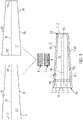
FIG. 1 is a schematic diagram illustrating a de-icer and components thereof in accordance with embodiments; -
FIG. 2 is a sectional view of an edge of the de-icer shown inFIG. 1 in accordance with embodiments; -
FIG. 3 is a perspective view of an aircraft including a de-icer as shown inFIG. 1 in accordance with embodiments; and -
FIG. 4 is a flow diagram illustrating a method of assembling a de-icer in accordance with embodiments. - As will be described below, a configuration of tubes in a de-icer is provided such that the last or outermost de-icer tube is parallel to an edge of the de-icer instead of the centerline of the de-icer. In some cases, that last or outermost tube is edge-parallel and formed with a reduced width as compared to the other tubes. The non-inflatable edge is used to prevent peeling or non-adhesion of the de-icer from the surface of the airfoil. The edge parallel reduced width tube provides for reduced loading on the edge stitchline whereby the non-inflatable edge can maintain better adhesion to the airfoil surface. With reduced loading on the non-inflatable edge offered by the last or outermost tube being edge-parallel with or without the last or outermost tube also having a reduced width, the non-inflatable edge can be narrower as compared to conventional non-inflatable edge widths.
- With reference to
FIGS. 1 and2 , a de-icer 101 is provided and includes a first carcassstructural material layer 110, a second carcassstructural material layer 120,edge sealing material 130,stitching 140, a bond layer 180 (seeFIG. 2 ) and an erosion layer 190(seeFIG. 2 ). The de-icer 101 can further include amanifold 170. - The first carcass
structural material layer 110 can have a trapezoidal (or, more particularly, rectangular)shape 111 with awide end 112, anarrow end 113, acenterline 114 extending between thewide end 112 and thenarrow end 113 and a tapered or non-inflatableedge 115. Thecenterline 114 is disposed at a normal angle with respect to thewide end 112 and thenarrow end 113. The tapered ornon-inflatable edge 115 is located at a first side of thecenterline 114 and extends between thewide end 112 and thenarrow end 113. The tapered ornon-inflatable edge 115 is angled with respect to thecenterline 114. The first carcassstructural material layer 110 can further include an additional tapered ornon-inflatable edge 116 at a second side of thecenterline 114. The additional tapered ornon-inflatable edge 116 extends between thewide end 112 and thenarrow end 113 and is angled with respect to thecenterline 114. The secondcarcass material layer 120 can have atrapezoidal shape 121 with awide end 122, anarrow end 123, acenterline 124 extending between thewide end 122 and thenarrow end 123 and a tapered ornon-inflatable edge 125. Thecenterline 124 is disposed at a normal angle with respect to thewide end 122 and thenarrow end 123. The tapered ornon-inflatable edge 125 is located at a first side of thecenterline 124 and extends between thewide end 122 and thenarrow end 123. The tapered ornon-inflatable edge 125 is angled with respect to thecenterline 124. The second carcassstructural material layer 120 can further include an additional tapered ornon-inflatable edge 126 at a second side of thecenterline 124. The additional tapered ornon-inflatable edge 126 extends between thewide end 122 and thenarrow end 123 and is angled with respect to thecenterline 124. - The
edge sealing material 130 is disposed to adhere the first and second carcass structural material layers 110 and 120 together to form anon-inflatable edge area 150. More particularly, theedge sealing material 130 is disposed to adhere the wide ends 112 and 122 together, the narrow ends 113 and 123 together, the tapered ornon-inflatable edges non-inflatable edges non-inflatable area 150 extends along at least the tapered ornon-inflatable edge 115 and the additional tapered ornon-inflatable edge 125 as well as the wide ends 112 and 122 and the narrow ends 113 and 123 and surrounds acentral area 160. - The
stitching 140 is disposed to stitch the first and second carcass structural material layers 110 and 120 together in thecentral area 160 to form tubes 1611-7. The manifold 170 is fluidly communicative with the tubes 1611-7 such that the tubes 1611-7 are inflatable and de-inflatable for de-icing operations. The tubes 1611-7 include an outermost tube 1611, which is closest to and parallel with the tapered ornon-inflatable edges non-inflatable area 150 extending along the tapered ornon-inflatable edges non-inflatable edges non-inflatable area 150 extending along the additional tapered ornon-inflatable edges centerlines centerlines - In accordance with embodiments, the
stitching 140 can have a substantially same, repeatingpattern 141 for defining each of the tubes 1611-7 and for particularly defining the outermost tube 1611 and the additional outermost tube 1612. - In accordance with further embodiments, the outermost tube 1611 and the additional outermost tube 1612 can be smaller (e.g., narrower) than the central interior tube 1613, the central intermediate tubes 1614, 5 and the central intermediate tubes 1616, 7.
- With the outermost tube 1611 being parallel with the tapered or
non-inflatable edges non-inflatable edges non-inflatable area 150 extending along the tapered ornon-inflatable edges non-inflatable edges non-inflatable area 150 extending along the tapered ornon-inflatable edges non-inflatable edges - For example, in a conventional instance of a de-icer, the non-inflatable area could have a width of 1.25 inches (3.175 cm) or more with 1.0 inches (2.54 cm) being an absolute minimum width. By contrast and in accordance with embodiments, the
non-inflatable area 150 extending along the tapered ornon-inflatable edges non-inflatable edges non-inflatable edge area 150 can have a constant or substantially constant width of about ~0.70 to about ~0.875 inches (~1.905 to about ~2.2225 cm). - With reference to
FIG. 2 , the sectional image is a view along the edge of the de-icer 101, showing some of thetubes 1601, 4, 5 and 3, the first and second carcass structural material layers 110 and 120, theedge sealing material 130, thestitching 141, thebond layer 180 and theerosion layer 190. - With reference to
FIG. 3 , anaircraft 301 is provided and may be configured as a turboprop aircraft for example. In any case, theaircraft 301 includes anaerodynamic surface 310, such as a wing, a de-icer 320 as described above operably disposed on theaerodynamic surface 310, and a control system configured to control operations of the de-icer 320. - It is to be understood that the de-icer 320 can be adhered or otherwise fastened to the
aerodynamic surface 310. In these or other cases, the tubes 1611-7 are inflated and deflated as described above during the operation of the de-icer 320 and the de-icer 320 remains adhered or otherwise fastened to the aerodynamic surface. This is achieved at least partly by the uniform loading resulting from the configuration of the outermost tube 1611 being parallel with the tapered ornon-inflatable edges non-inflatable edges - With reference to
FIG. 4 , a method of assembling a de-icer as described above is provided. As shown inFIG. 4 , the method includes forming first and second carcass structural material layers to each include a centerline and an edge angled with respect to the centerline (401), adhering the first and second carcass structural material layers together to form a non-inflatable edge area extending along at least the edge and surrounding a central area (402) and stitching the first and second carcass structural material layers together in the central area to form tubes including an outermost tube which is closest to and parallel with the edge (403). - Technical effects and benefits of the present disclosure are the provision of a last or outermost de-icer tube of a de-icer, which is parallel with the edge of the de-icer and which has a relatively reduced size as compared to the other tubes in the de-icer. This results in loading on the non-inflatable edge of the de-icer being reduced and thus allowing for a relatively narrow non-inflatable edge.
- The corresponding structures, materials, acts, and equivalents of all means or step plus function elements in the claims below are intended to include any structure, material, or act for performing the function in combination with other claimed elements as specifically claimed. The description of the present disclosure has been presented for purposes of illustration and description, but is not intended to be exhaustive or limited to the technical concepts in the form disclosed. Many modifications and variations will be apparent to those of ordinary skill in the art without departing from the scope and spirit of the disclosure. The embodiments were chosen and described in order to best explain the principles of the disclosure and the practical application, and to enable others of ordinary skill in the art to understand the disclosure for various embodiments with various modifications as are suited to the particular use contemplated.
- While the preferred embodiments to the disclosure have been described, it will be understood that those skilled in the art, both now and in the future, may make various improvements and enhancements which fall within the scope of the claims which follow. These claims should be construed to maintain the proper protection for the disclosure first described.
Claims (12)
- A de-icer, comprising:first (110) and second (120) structural layers each comprising a centerline (114) and a non-inflatable edge (115) angled with respect to the centerline;edge sealing material (130) disposed to adhere the first and second structural layers together to form a non-inflatable edge area extending along at least the non-inflatable edge and surrounding a central area; andstitching (140) disposed to stitch the first and second structural layers together in the central area to form tubes (161) comprising an outermost tube (1611) which is closest to and parallel with the non-inflatable edge.
- The de-icer according to claim 1, wherein the first and second structural layers each have a trapezoidal shape (111) with the non-inflatable edge and an additional non-inflatable edge on opposite sides of the centerline.
- The de-icer according to claim 2, wherein the tubes comprise:multiple central tubes (1614,5) which are parallel with the centerline;the outermost tube (1611); andan additional outermost tube (1612) which is closest to and parallel with the additional non-inflatable edge.
- The de-icer according to any preceding claim, wherein the stitching (140) has a same pattern for each of the tubes and the outermost tube.
- The de-icer according to any preceding claim, wherein the non-inflatable edge area is about ~0.5 to about ~0.9375 inches (~1.27 to about ~2.38125 cm) wide.
- The de-icer according to any preceding claim, wherein the non-inflatable edge area is about ~0.75 to about ~0.875 inches (~1.905 to about ~2.2225 cm) wide.
- The de-icer according to any preceding claim, wherein the outermost tube is narrower than at least one of the other tubes.
- The de-icer of any preceding claim, comprising:the first and second structural layers, each comprising wide (112, 122) and narrow (113, 123) ends, the centerline extending between the wide and narrow ends and the non-inflatable edge extending between the wide and narrow ends; andthe tubes being inflatable and de-inflatable for de-icing operations.
- The de-icer according to claim 8 when dependent on claim 3, wherein the non-inflatable edge area extends along the wide and narrow ends, the non-inflatable edge and the additional non-inflatable edge.
- An aircraft, comprising:an aerodynamic surface; anda de-icer (101) according to any preceding claim operably disposed on the aerodynamic surface.
- The aircraft according to claim 10, wherein the de-icer remains adhered to the aerodynamic surface during inflation and deflation of the tubes.
- A method of assembling a de-icer, the method comprising:forming first and second structural layers to each comprise a centerline and a non-inflatable edge angled with respect to the centerline;adhering the first and second structural layers together to form a non-inflatable edge area extending along at least the non-inflatable edge and surrounding a central area; andstitching the first and second structural layers together in the central area to form tubes comprising an outermost tube which is closest to and parallel with the non-inflatable edge.
Applications Claiming Priority (1)
| Application Number | Priority Date | Filing Date | Title |
|---|---|---|---|
| US17/333,227 US11511868B1 (en) | 2021-05-28 | 2021-05-28 | Pneumatic de-icer with reduced non-inflatable area at de-icer edge |
Publications (2)
| Publication Number | Publication Date |
|---|---|
| EP4095041A1 true EP4095041A1 (en) | 2022-11-30 |
| EP4095041B1 EP4095041B1 (en) | 2024-10-09 |
Family
ID=81850856
Family Applications (1)
| Application Number | Title | Priority Date | Filing Date |
|---|---|---|---|
| EP22175933.5A Active EP4095041B1 (en) | 2021-05-28 | 2022-05-27 | Pneumatic de-icer with reduced non-inflatable area at deicer edge |
Country Status (2)
| Country | Link |
|---|---|
| US (1) | US11511868B1 (en) |
| EP (1) | EP4095041B1 (en) |
Citations (4)
| Publication number | Priority date | Publication date | Assignee | Title |
|---|---|---|---|---|
| GB2139586A (en) * | 1983-05-09 | 1984-11-14 | Goodrich Co B F | Deicer for aircraft |
| GB2167723A (en) * | 1984-12-03 | 1986-06-04 | Goodrich Co B F | Pneumatic deicer |
| US5310142A (en) * | 1992-10-30 | 1994-05-10 | The B. F. Goodrich Company | Dimple pattern pneumatic deicer assembly |
| US5449133A (en) * | 1993-07-30 | 1995-09-12 | The B. F. Goodrich Company | Pneumatic de-icer having improved aerodynamic characteristics |
Family Cites Families (6)
| Publication number | Priority date | Publication date | Assignee | Title |
|---|---|---|---|---|
| US5112011A (en) | 1989-12-04 | 1992-05-12 | The B. F. Goodrich Company | Pneumatic deicer for shedding thin ice |
| US5337978A (en) * | 1992-10-29 | 1994-08-16 | The B.F. Goodrich Company | Leading edge pneumatic deicer assembly |
| US5813631A (en) | 1996-02-26 | 1998-09-29 | The B. F. Goodrich Company | Pneumatic deicing system with drain valve |
| US9598176B2 (en) * | 2015-01-27 | 2017-03-21 | Goodrich Corporation | Health monitoring pneumatic deicer |
| US10780984B2 (en) * | 2017-04-20 | 2020-09-22 | Goodrich Corporation | Sewn reinforcement features for prevention of stitch breakage in a pneumatic de-icer |
| US10640217B2 (en) * | 2017-07-14 | 2020-05-05 | Goodrich Corporation | Pneumatic deicer with sensors |
-
2021
- 2021-05-28 US US17/333,227 patent/US11511868B1/en active Active
-
2022
- 2022-05-27 EP EP22175933.5A patent/EP4095041B1/en active Active
Patent Citations (4)
| Publication number | Priority date | Publication date | Assignee | Title |
|---|---|---|---|---|
| GB2139586A (en) * | 1983-05-09 | 1984-11-14 | Goodrich Co B F | Deicer for aircraft |
| GB2167723A (en) * | 1984-12-03 | 1986-06-04 | Goodrich Co B F | Pneumatic deicer |
| US5310142A (en) * | 1992-10-30 | 1994-05-10 | The B. F. Goodrich Company | Dimple pattern pneumatic deicer assembly |
| US5449133A (en) * | 1993-07-30 | 1995-09-12 | The B. F. Goodrich Company | Pneumatic de-icer having improved aerodynamic characteristics |
Also Published As
| Publication number | Publication date |
|---|---|
| EP4095041B1 (en) | 2024-10-09 |
| US20220380056A1 (en) | 2022-12-01 |
| US11511868B1 (en) | 2022-11-29 |
Similar Documents
| Publication | Publication Date | Title |
|---|---|---|
| US6520452B1 (en) | Deicer for aircraft | |
| US6443394B1 (en) | Inflatable airfoil device | |
| US7900871B2 (en) | Wing leading edge having vortex generators | |
| EP3415435B1 (en) | Improved tube type pneumatic deicers | |
| EP0554860B1 (en) | Airfoil with integral de-icer using overlapped tubes | |
| US4613102A (en) | Pneumatic deicers with template | |
| US3623684A (en) | Deicing device | |
| EP0604751A1 (en) | Compressible nose dynamic deicer | |
| EP3428067B1 (en) | Pneumatic deicer with sensors | |
| EP3235732B1 (en) | Pneumatic de-icer with sensor for supercooled large droplet icing detection | |
| EP3738884B1 (en) | Pneumatic deicer with runback channels | |
| EP3378779A1 (en) | Asymmestric yoke | |
| EP3889047B1 (en) | Continuous stacked dual wrap tube end closure for anti-icing systems | |
| EP3498608A1 (en) | Sewn alternate inflate pneumatic de-icer | |
| EP3392147B1 (en) | Sewn reinforcement features for prevention of stitch breakage in a pneumatic de-icer | |
| US4516745A (en) | Pneumatic deicer and deicing method | |
| EP4095041B1 (en) | Pneumatic de-icer with reduced non-inflatable area at deicer edge | |
| US5449133A (en) | Pneumatic de-icer having improved aerodynamic characteristics | |
| US5449134A (en) | Apparatus and method for providing a pneumatic de-icer with a replaceable environment resistant surface | |
| US11198513B1 (en) | Anti-icing/de-icing system and method | |
| EP3604135B1 (en) | Deicing boot utilizing electromagnetism and magnetics for boot inflation | |
| EP4603389A2 (en) | Pneumatic deicing system integrated with an air management system and advanced inlet air connection valve |
Legal Events
| Date | Code | Title | Description |
|---|---|---|---|
| PUAI | Public reference made under article 153(3) epc to a published international application that has entered the european phase |
Free format text: ORIGINAL CODE: 0009012 |
|
| STAA | Information on the status of an ep patent application or granted ep patent |
Free format text: STATUS: THE APPLICATION HAS BEEN PUBLISHED |
|
| AK | Designated contracting states |
Kind code of ref document: A1 Designated state(s): AL AT BE BG CH CY CZ DE DK EE ES FI FR GB GR HR HU IE IS IT LI LT LU LV MC MK MT NL NO PL PT RO RS SE SI SK SM TR |
|
| STAA | Information on the status of an ep patent application or granted ep patent |
Free format text: STATUS: REQUEST FOR EXAMINATION WAS MADE |
|
| 17P | Request for examination filed |
Effective date: 20230530 |
|
| RBV | Designated contracting states (corrected) |
Designated state(s): AL AT BE BG CH CY CZ DE DK EE ES FI FR GB GR HR HU IE IS IT LI LT LU LV MC MK MT NL NO PL PT RO RS SE SI SK SM TR |
|
| P01 | Opt-out of the competence of the unified patent court (upc) registered |
Effective date: 20230922 |
|
| GRAP | Despatch of communication of intention to grant a patent |
Free format text: ORIGINAL CODE: EPIDOSNIGR1 |
|
| STAA | Information on the status of an ep patent application or granted ep patent |
Free format text: STATUS: GRANT OF PATENT IS INTENDED |
|
| INTG | Intention to grant announced |
Effective date: 20240502 |
|
| RAP3 | Party data changed (applicant data changed or rights of an application transferred) |
Owner name: GOODRICH CORPORATION |
|
| GRAS | Grant fee paid |
Free format text: ORIGINAL CODE: EPIDOSNIGR3 |
|
| GRAA | (expected) grant |
Free format text: ORIGINAL CODE: 0009210 |
|
| STAA | Information on the status of an ep patent application or granted ep patent |
Free format text: STATUS: THE PATENT HAS BEEN GRANTED |
|
| AK | Designated contracting states |
Kind code of ref document: B1 Designated state(s): AL AT BE BG CH CY CZ DE DK EE ES FI FR GB GR HR HU IE IS IT LI LT LU LV MC MK MT NL NO PL PT RO RS SE SI SK SM TR |
|
| REG | Reference to a national code |
Ref country code: CH Ref legal event code: EP |
|
| REG | Reference to a national code |
Ref country code: DE Ref legal event code: R096 Ref document number: 602022006615 Country of ref document: DE |
|
| REG | Reference to a national code |
Ref country code: IE Ref legal event code: FG4D |
|
| REG | Reference to a national code |
Ref country code: LT Ref legal event code: MG9D |
|
| REG | Reference to a national code |
Ref country code: NL Ref legal event code: MP Effective date: 20241009 |
|
| REG | Reference to a national code |
Ref country code: AT Ref legal event code: MK05 Ref document number: 1730356 Country of ref document: AT Kind code of ref document: T Effective date: 20241009 |
|
| PG25 | Lapsed in a contracting state [announced via postgrant information from national office to epo] |
Ref country code: NL Free format text: LAPSE BECAUSE OF FAILURE TO SUBMIT A TRANSLATION OF THE DESCRIPTION OR TO PAY THE FEE WITHIN THE PRESCRIBED TIME-LIMIT Effective date: 20241009 |
|
| PG25 | Lapsed in a contracting state [announced via postgrant information from national office to epo] |
Ref country code: NL Free format text: LAPSE BECAUSE OF FAILURE TO SUBMIT A TRANSLATION OF THE DESCRIPTION OR TO PAY THE FEE WITHIN THE PRESCRIBED TIME-LIMIT Effective date: 20241009 |
|
| PG25 | Lapsed in a contracting state [announced via postgrant information from national office to epo] |
Ref country code: HR Free format text: LAPSE BECAUSE OF FAILURE TO SUBMIT A TRANSLATION OF THE DESCRIPTION OR TO PAY THE FEE WITHIN THE PRESCRIBED TIME-LIMIT Effective date: 20241009 Ref country code: IS Free format text: LAPSE BECAUSE OF FAILURE TO SUBMIT A TRANSLATION OF THE DESCRIPTION OR TO PAY THE FEE WITHIN THE PRESCRIBED TIME-LIMIT Effective date: 20250209 Ref country code: PT Free format text: LAPSE BECAUSE OF FAILURE TO SUBMIT A TRANSLATION OF THE DESCRIPTION OR TO PAY THE FEE WITHIN THE PRESCRIBED TIME-LIMIT Effective date: 20250210 |
|
| PG25 | Lapsed in a contracting state [announced via postgrant information from national office to epo] |
Ref country code: FI Free format text: LAPSE BECAUSE OF FAILURE TO SUBMIT A TRANSLATION OF THE DESCRIPTION OR TO PAY THE FEE WITHIN THE PRESCRIBED TIME-LIMIT Effective date: 20241009 |
|
| PG25 | Lapsed in a contracting state [announced via postgrant information from national office to epo] |
Ref country code: BG Free format text: LAPSE BECAUSE OF FAILURE TO SUBMIT A TRANSLATION OF THE DESCRIPTION OR TO PAY THE FEE WITHIN THE PRESCRIBED TIME-LIMIT Effective date: 20241009 |
|
| PG25 | Lapsed in a contracting state [announced via postgrant information from national office to epo] |
Ref country code: ES Free format text: LAPSE BECAUSE OF FAILURE TO SUBMIT A TRANSLATION OF THE DESCRIPTION OR TO PAY THE FEE WITHIN THE PRESCRIBED TIME-LIMIT Effective date: 20241009 |
|
| PG25 | Lapsed in a contracting state [announced via postgrant information from national office to epo] |
Ref country code: NO Free format text: LAPSE BECAUSE OF FAILURE TO SUBMIT A TRANSLATION OF THE DESCRIPTION OR TO PAY THE FEE WITHIN THE PRESCRIBED TIME-LIMIT Effective date: 20250109 |
|
| PG25 | Lapsed in a contracting state [announced via postgrant information from national office to epo] |
Ref country code: AT Free format text: LAPSE BECAUSE OF FAILURE TO SUBMIT A TRANSLATION OF THE DESCRIPTION OR TO PAY THE FEE WITHIN THE PRESCRIBED TIME-LIMIT Effective date: 20241009 Ref country code: LV Free format text: LAPSE BECAUSE OF FAILURE TO SUBMIT A TRANSLATION OF THE DESCRIPTION OR TO PAY THE FEE WITHIN THE PRESCRIBED TIME-LIMIT Effective date: 20241009 Ref country code: GR Free format text: LAPSE BECAUSE OF FAILURE TO SUBMIT A TRANSLATION OF THE DESCRIPTION OR TO PAY THE FEE WITHIN THE PRESCRIBED TIME-LIMIT Effective date: 20250110 |
|
| PG25 | Lapsed in a contracting state [announced via postgrant information from national office to epo] |
Ref country code: PL Free format text: LAPSE BECAUSE OF FAILURE TO SUBMIT A TRANSLATION OF THE DESCRIPTION OR TO PAY THE FEE WITHIN THE PRESCRIBED TIME-LIMIT Effective date: 20241009 |
|
| PG25 | Lapsed in a contracting state [announced via postgrant information from national office to epo] |
Ref country code: RS Free format text: LAPSE BECAUSE OF FAILURE TO SUBMIT A TRANSLATION OF THE DESCRIPTION OR TO PAY THE FEE WITHIN THE PRESCRIBED TIME-LIMIT Effective date: 20250109 |
|
| PG25 | Lapsed in a contracting state [announced via postgrant information from national office to epo] |
Ref country code: SM Free format text: LAPSE BECAUSE OF FAILURE TO SUBMIT A TRANSLATION OF THE DESCRIPTION OR TO PAY THE FEE WITHIN THE PRESCRIBED TIME-LIMIT Effective date: 20241009 |
|
| PGFP | Annual fee paid to national office [announced via postgrant information from national office to epo] |
Ref country code: DE Payment date: 20250423 Year of fee payment: 4 |
|
| PG25 | Lapsed in a contracting state [announced via postgrant information from national office to epo] |
Ref country code: DK Free format text: LAPSE BECAUSE OF FAILURE TO SUBMIT A TRANSLATION OF THE DESCRIPTION OR TO PAY THE FEE WITHIN THE PRESCRIBED TIME-LIMIT Effective date: 20241009 |
|
| REG | Reference to a national code |
Ref country code: DE Ref legal event code: R097 Ref document number: 602022006615 Country of ref document: DE |
|
| PG25 | Lapsed in a contracting state [announced via postgrant information from national office to epo] |
Ref country code: EE Free format text: LAPSE BECAUSE OF FAILURE TO SUBMIT A TRANSLATION OF THE DESCRIPTION OR TO PAY THE FEE WITHIN THE PRESCRIBED TIME-LIMIT Effective date: 20241009 |
|
| PGFP | Annual fee paid to national office [announced via postgrant information from national office to epo] |
Ref country code: FR Payment date: 20250423 Year of fee payment: 4 |
|
| PG25 | Lapsed in a contracting state [announced via postgrant information from national office to epo] |
Ref country code: RO Free format text: LAPSE BECAUSE OF FAILURE TO SUBMIT A TRANSLATION OF THE DESCRIPTION OR TO PAY THE FEE WITHIN THE PRESCRIBED TIME-LIMIT Effective date: 20241009 |
|
| PG25 | Lapsed in a contracting state [announced via postgrant information from national office to epo] |
Ref country code: SK Free format text: LAPSE BECAUSE OF FAILURE TO SUBMIT A TRANSLATION OF THE DESCRIPTION OR TO PAY THE FEE WITHIN THE PRESCRIBED TIME-LIMIT Effective date: 20241009 |
|
| PG25 | Lapsed in a contracting state [announced via postgrant information from national office to epo] |
Ref country code: CZ Free format text: LAPSE BECAUSE OF FAILURE TO SUBMIT A TRANSLATION OF THE DESCRIPTION OR TO PAY THE FEE WITHIN THE PRESCRIBED TIME-LIMIT Effective date: 20241009 |
|
| PG25 | Lapsed in a contracting state [announced via postgrant information from national office to epo] |
Ref country code: IT Free format text: LAPSE BECAUSE OF FAILURE TO SUBMIT A TRANSLATION OF THE DESCRIPTION OR TO PAY THE FEE WITHIN THE PRESCRIBED TIME-LIMIT Effective date: 20241009 |
|
| PLBE | No opposition filed within time limit |
Free format text: ORIGINAL CODE: 0009261 |
|
| STAA | Information on the status of an ep patent application or granted ep patent |
Free format text: STATUS: NO OPPOSITION FILED WITHIN TIME LIMIT |
|
| PG25 | Lapsed in a contracting state [announced via postgrant information from national office to epo] |
Ref country code: SE Free format text: LAPSE BECAUSE OF FAILURE TO SUBMIT A TRANSLATION OF THE DESCRIPTION OR TO PAY THE FEE WITHIN THE PRESCRIBED TIME-LIMIT Effective date: 20241009 |
|
| 26N | No opposition filed |
Effective date: 20250710 |
|
| REG | Reference to a national code |
Ref country code: CH Ref legal event code: H13 Free format text: ST27 STATUS EVENT CODE: U-0-0-H10-H13 (AS PROVIDED BY THE NATIONAL OFFICE) Effective date: 20251223 |
|
| PG25 | Lapsed in a contracting state [announced via postgrant information from national office to epo] |
Ref country code: LU Free format text: LAPSE BECAUSE OF NON-PAYMENT OF DUE FEES Effective date: 20250527 |
|
| PG25 | Lapsed in a contracting state [announced via postgrant information from national office to epo] |
Ref country code: CH Free format text: LAPSE BECAUSE OF NON-PAYMENT OF DUE FEES Effective date: 20250531 |
|
| REG | Reference to a national code |
Ref country code: BE Ref legal event code: MM Effective date: 20250531 |
|
| PG25 | Lapsed in a contracting state [announced via postgrant information from national office to epo] |
Ref country code: MC Free format text: LAPSE BECAUSE OF FAILURE TO SUBMIT A TRANSLATION OF THE DESCRIPTION OR TO PAY THE FEE WITHIN THE PRESCRIBED TIME-LIMIT Effective date: 20241009 |
|
| PG25 | Lapsed in a contracting state [announced via postgrant information from national office to epo] |
Ref country code: IE Free format text: LAPSE BECAUSE OF NON-PAYMENT OF DUE FEES Effective date: 20250527 |
|
| PG25 | Lapsed in a contracting state [announced via postgrant information from national office to epo] |
Ref country code: BE Free format text: LAPSE BECAUSE OF NON-PAYMENT OF DUE FEES Effective date: 20250531 |