EP4094950A1 - Liquid discharge apparatus, image forming apparatus, and liquid discharge method - Google Patents
Liquid discharge apparatus, image forming apparatus, and liquid discharge method Download PDFInfo
- Publication number
- EP4094950A1 EP4094950A1 EP22167149.8A EP22167149A EP4094950A1 EP 4094950 A1 EP4094950 A1 EP 4094950A1 EP 22167149 A EP22167149 A EP 22167149A EP 4094950 A1 EP4094950 A1 EP 4094950A1
- Authority
- EP
- European Patent Office
- Prior art keywords
- resin layer
- resin
- mixed liquid
- physical property
- liquid
- Prior art date
- Legal status (The legal status is an assumption and is not a legal conclusion. Google has not performed a legal analysis and makes no representation as to the accuracy of the status listed.)
- Granted
Links
Images



Classifications
-
- B—PERFORMING OPERATIONS; TRANSPORTING
- B41—PRINTING; LINING MACHINES; TYPEWRITERS; STAMPS
- B41J—TYPEWRITERS; SELECTIVE PRINTING MECHANISMS, i.e. MECHANISMS PRINTING OTHERWISE THAN FROM A FORME; CORRECTION OF TYPOGRAPHICAL ERRORS
- B41J11/00—Devices or arrangements of selective printing mechanisms, e.g. ink-jet printers or thermal printers, for supporting or handling copy material in sheet or web form
- B41J11/0015—Devices or arrangements of selective printing mechanisms, e.g. ink-jet printers or thermal printers, for supporting or handling copy material in sheet or web form for treating before, during or after printing or for uniform coating or laminating the copy material before or after printing
-
- B—PERFORMING OPERATIONS; TRANSPORTING
- B41—PRINTING; LINING MACHINES; TYPEWRITERS; STAMPS
- B41J—TYPEWRITERS; SELECTIVE PRINTING MECHANISMS, i.e. MECHANISMS PRINTING OTHERWISE THAN FROM A FORME; CORRECTION OF TYPOGRAPHICAL ERRORS
- B41J15/00—Devices or arrangements of selective printing mechanisms, e.g. ink-jet printers or thermal printers, specially adapted for supporting or handling copy material in continuous form, e.g. webs
Definitions
- An aspect of the present disclosure relates to a liquid discharge apparatus, an image forming apparatus, and a liquid discharge method.
- a liquid discharge apparatus applies (coats) a resin layer containing a polyvinyl chloride resin or the like containing a plasticizer on a substrate and discharges a liquid such as ink to apply droplets on the resin layer.
- Such liquid discharge apparatus includes an apparatus that forms an image on the substrate by a liquid discharge method to manufacture a sheet-like wallpaper.
- the liquid discharging apparatus controls an application amount of an aggregating agent applied onto the substrate such as a paper to adjust a diameter of droplets discharged onto the resin layer containing the aggregating agent or the like (see Japanese Unexamined Patent Application Publication No. 2010-184479 , for example).
- the resin layer applied onto the substrate changes its physical properties such as viscosity according to a surrounding environment such as temperature and humidity. Therefore, a state of spread of the droplet applied onto the resin layer is changed according to the physical properties of the resin layer. Thus, a state of the droplets on the resin layer is not stable. Thus, quality of an image or the like formed on the resin layer may not be stable.
- a liquid discharge apparatus includes a conveyor configured to convey a substrate in a conveyance direction; a resin layer applier configured to apply a resin layer containing a resin onto the substrate conveyed by the conveyor, a liquid discharger configured to discharge a liquid onto the resin layer to apply a droplet onto the resin layer, an acquirer configured to acquire a physical property of the resin layer, an adjuster configured to adjust the physical property of the resin layer, and circuitry configured to control the adjuster to control the physical property of the resin layer according to the physical property acquired by the acquirer.
- a liquid discharge method includes conveying a substrate in a conveyance direction, applying a resin layer containing a resin onto the substrate; discharging a liquid onto the resin layer to apply a droplet onto the resin layer, acquiring a physical property of the resin layer; adjusting the physical property of the resin layer, and controlling the physical property of the resin layer according to the physical property acquired by the acquiring.
- the liquid discharge apparatus can stabilize the state of the droplet applied on the resin layer.
- liquid discharged from a head is not particularly limited as long as the liquid has a viscosity and surface tension of degrees dischargeable from the head.
- the viscosity of the liquid is not greater than 30 mPa ⁇ s under ordinary temperature and ordinary pressure or by heating or cooling.
- the liquid examples include a solution, a suspension, or an emulsion that contains, for example, a solvent, such as water or an organic solvent, a colorant, such as dye or pigment, a functional material, such as a polymerizable compound, a resin, or a surfactant, a biocompatible material, such as deoxyribonucleic acid (DNA), amino acid, protein, or calcium, or an edible material, such as a natural colorant.
- a solvent such as water or an organic solvent
- a colorant such as dye or pigment
- a functional material such as a polymerizable compound, a resin, or a surfactant
- a biocompatible material such as deoxyribonucleic acid (DNA), amino acid, protein, or calcium
- an edible material such as a natural colorant.
- the liquid can be used, for example, in applications such as ink jet inks.
- the liquid discharger is a functional component that discharges and jets a liquid from a nozzle.
- Examples of an energy source for generating energy to discharge liquid include a piezoelectric actuator (a laminated piezoelectric element or a thin-film piezoelectric element), a thermal actuator that employs a thermoelectric conversion element, such as a thermal resistor, and an electrostatic actuator including a diaphragm and opposed electrodes.
- FIG. 1 is a schematic side view of an overall configuration of an image forming apparatus 100 according to a first embodiment of the present disclosure.
- the image forming apparatus 100 includes a resin layer applier 1, a conveyor 2, a liquid discharger 3, a reader 4, a controller 5, and an adjuster 6.
- the image forming apparatus 100 drives a resin layer applier 1 to apply a resin layer 30 (see FIG. 8 ) to a substrate 10.
- the image forming apparatus 100 further drives the liquid discharger 3 to discharges a liquid onto the resin layer 30 applied onto the substrate 10 to apply the liquid.
- the controller 5 of the image forming apparatus 100 controls the adjuster 6 to adjust physical properties of the resin layer 30 according to a reading result of the reader 4 that reads a pattern formed by the droplets applied on the resin layer 30.
- the image forming apparatus 100 applies droplets onto the resin layer 30 applied on the substrate 10 to form an image to manufacture the substrate 10 as a wallpaper.
- Material of the substrate 10 is not particularly limited as long as the material has suitable mechanical strength, heat resistance, and the like as a substrate of a wallpaper.
- a common substrate such as a paper and nonwoven fabric may be used as a wallpaper. More specifically, a natural paper, a plastic film, a synthetic paper, non-woven fabric, cloth, wood, metal thin-film and the like may be used as the substrate 10.
- the material of the substrate 10 is selected according to an application of the substrate 10.
- the resin layer applier 1 applies (coats) a resin layer 30 containing resin to at least one surface of a smooth substrate 10 made of paper or non-woven fabric.
- Vinyl chloride resin, acrylic resin or the like can be used as the resin contained in the resin layer 30 to manufacture the wallpaper.
- the resin layer 30 may contain a plasticizer or may contain a plasticizer and a heating foaming agent.
- the resin layer 30 is applied (coated) on the substrate 10 in a state in which at least a vinyl chloride resin contains a plasticizer.
- the conveyor 2 includes a conveyance roller 21, a preheat drum 22, and a heating drum 23.
- the conveyor 2 rotates each of the conveyance roller 21, the preheat drum 22, and the heating drum 23.to convey the substrate 10 stretched around the conveyance roller 21, the preheat drum 22, and the heating drum 23 along the predetermined conveyance direction 20.
- the conveyor 2 may further include other rollers or drums used for conveying the substrate 10.
- the conveyor 2 includes a preheat drum 22 and a heating drum 23 on a downstream of the resin layer applier 1 in the conveyance direction 20 as indicated by arrow in FIG. 1 .
- Each of the preheat drum 22 and the heating drum 23 includes a heater inside the preheat drum 22 and the heating drum 23.
- Each of the preheat drum 22 and the heating drum 23 use the heater to heat the substrate 10 contacting an outer peripheral surface of the preheat drum 22 and the heating drum 23 while conveying the substrate 10.
- the preheat drum 22 preheats the substrate 10 applied (coated) with the resin layer 30.
- the heating drum 23 conveys a region of the substrate 10 applied (coated) with the resin layer 30 to a position facing the liquid discharger 3 while heating the substrate 10 to a substantially constant temperature.
- the resin heated by the preheat drum 22 and the heating drum 23 gels so that the resin layer 30 is fixed on the substrate 10.
- the image forming apparatus 100 preferably includes the heating drum 23 and the like to heat the resin layer 30 after applying (coating) the resin layer 30 on the substrate 10 from a viewpoint of stably fixing the resin layer 30 on the substrate 10.
- the image forming apparatus 100 includes the liquid discharger 3 in a downstream of the resin layer applier 1 in the conveyance direction 20.
- the liquid discharger 3 discharge droplets onto the resin layer 30 of the substrate 10 conveyed by the heating drum 23 to apply droplets on the resin layer 30 after the resin layer applier 1 applies the resin layer 30 on the substrate 10.
- the liquid discharger 3 includes liquid discharge heads 3A, 3B, 3C and 3D.
- the “liquid discharge head” is simply referred to as a "head”.
- the heads 3A, 3B, 3C and 3D are arrayed in parallel along the conveyance direction 20 to sequentially discharge a liquid toward the conveyed substrate 10.
- Each of the heads 3A, 3B, 3C and 3D may discharge liquid of the same color or liquid of different color.
- the heads 3A, 3B, 3C and 3D discharges liquid of cyan, magenta, yellow, and black to form a full-color image on the resin layer 30.
- the liquid discharged from the liquid discharger 3 is, for example, an oil-based ink having no curing reactivity as a liquid.
- the oil-based ink contains at least an oil-based component and a coloring agent, and may contain a binder resin if necessary.
- the oil-based ink preferably contains 80% by mass or more of an oil-based component having a boiling point of 200°C or higher.
- the oil-based component of the oil-based ink preferably contains ester oil as a main component.
- the oil-based ink discharged from the liquid discharger 3 contains an oil-based component and a coloring agent.
- a content of the ester oil is preferably 30% by mass or more, more preferably 50% by mass or more and 90% by mass or less.
- the oil-based ink may contain 5% by mass or less of water.
- the reader 4 is an example of an acquirer to acquire physical property information of the resin layer 30.
- the reader 4 is an in-line sensor that includes pixels such as a charge coupled device (CCD) and a complementary metal oxide semiconductor (CMOS) in a line shape.
- CCD charge coupled device
- CMOS complementary metal oxide semiconductor
- the reader 4 is disposed such that pixels are arrayed in a direction substantially orthogonal to the conveyance direction 20.
- the reader 4 reads the pattern formed on the resin layer 30 on the substrate 10 conveyed along the conveyance direction 20 to shoot a two-dimensional pattern.
- the reader 4 is not limited to the in-line sensor, and may include a two-dimensional imaging element in which pixels such as the CCD and the CMOS are two dimensionally arrayed.
- the image forming apparatus 100 When the reader 4 reads the physical properties of the resin layer 30, the image forming apparatus 100 first drives the liquid discharger 3 to form a predetermined adjustment pattern (predetermined pattern) on the resin layer 30 to acquire the physical property information of the resin layer 30. Then, the reader 4 reads the adjustment pattern formed on the resin layer 30.
- the reader 4 is disposed downstream of the liquid discharger 3 in the conveyance direction 20.
- the adjustment pattern is, for example, a dot pattern formed by droplets.
- the physical property of the resin layer 30 to be acquired is viscosity, for example.
- the droplets applied on the resin layer 30 spread differently according to the viscosity of the resin layer 30.
- the reader 4 reads an image of a dot pattern formed by the droplets and outputs a read image to the controller 5.
- the viscosity of the resin layer 30 is an example of the physical properties of the resin layer 30.
- the controller 5 controls a liquid discharge operation by the liquid discharger 3, a conveyance operation of the substrate 10 by the conveyor 2, and an adjustment operation of the adjuster 6 based on viscosity information of the resin layer 30.
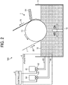
- FIG. 2 is a schematic side view of an example of configuration of the resin layer applier 1 and the adjuster 6 according to the first embodiment of the present disclosure.
- the resin layer applier 1 includes a mixed liquid storage 11, a stirrer 12, an application roller 13, and a blade 14.
- a resin layer applier 1 coats the substrate 10 with the resin layer 30 formed from a mixed liquid 15 of a resin and a diluent that dilutes the mixed liquid to change a rate of the resin contained in the resin layer 30.
- the diluent include water, thinner, and organic solvent.
- the mixed liquid storage 11 is a container to store the mixed liquid 15. A vertically upper part of the mixed liquid storage 11 is open to the atmosphere.
- the stirrer 12 includes blades rotatably disposed inside the mixed liquid storage 11.
- the stirrer 12 rotates and stirs the mixed liquid 15 stored in the mixed liquid storage 11.
- the stirrer 12 stirs the mixed liquid 15 so that the ratio of the resin to the diluent is substantially constant over the entire mixed liquid 15.
- the substrate 10 is stretched around an outer peripheral surface of the application roller 13.
- the application roller 13 is immersible a part of the substrate 10 in the mixed liquid 15 through a vertically upper part of the mixed liquid storage 11 opening to the atmosphere.
- the substrate 10 is stretched around the application roller 13 as described above.
- the mixed liquid 15 is adhered to an immersed region of the substrate 10 immersed in the mixed liquid 15.
- the blade 14 is disposed on a downstream of the immersed region of the substrate 10 in the conveyance direction 20. A leading edge of the blade 14 is brought into contact with the surface of the substrate 10 conveyed along the conveyance direction 20. Thus, the blade 14 regulates a thickness of the mixed liquid 15 adhered onto the surface of the substrate 10 so that the thickness of the mixed liquid 15 becomes substantially constant. As a result, the mixed liquid 15 is applied onto the surface of the substrate 10 at a substantially constant thickness. Thus, the resin layer 30 made of the mixed liquid 15 is applied (coated) on the substrate 10.
- Examples of methods of applying the resin layer 30 onto the substrate 10 by the resin layer applier 1 includes, but not limited to, a nozzle coating method, a die coating method, a lip coating method, a comma coating method, a gravure coating method, a rotary screen coating method, a reverse roll coating method, and the like in addition to the methods described above.
- the adjuster 6 includes a diluent tank 61, a diluent switch valve 62, a diluent supply nozzle 63, a resin tank 64, a resin switch valve 65, and a resin supply nozzle 66.
- the adjuster 6 supplies at least one of a resin or a diluent to the mixed liquid storage 11 to adjust the physical properties of the resin layer 30 applied to the substrate 10. Any liquid may be used as the diluent as long as the liquid is dilutable viscosity and other physical properties of the mixed liquid 15.
- the diluent tank 61 is a container to store a diluent.
- One end of the diluent supply nozzle 63 is connected to the diluent tank 61 via the diluent switch valve 62.
- the diluent switch valve 62 is an electromagnetic valve switchable in response to a control signal from the controller 5.
- Another end of the diluent supply nozzle 63 is coupled (connected) to the mixed liquid storage 11.
- the diluent tank 61 and the mixed liquid storage 11 communicate with each other through a diluent supply nozzle 63.
- the diluent tank 61 is disposed such that a liquid level of the diluent stored in the diluent tank 61 is higher than a liquid level of the mixed liquid 15 in the mixed liquid storage 11 in a vertical direction. Therefore, the diluent in the diluent tank 61 flows toward the mixed liquid storage 11 by the water head pressure and is supplied to the mixed liquid storage 11 in response to an opening of the diluent switch valve 62. Supply of the diluent to the mixed liquid storage 11 is stopped in response to a closing of the diluent switch valve 62.
- the resin tank 64 is a container to store a liquid resin.
- One end of the resin supply nozzle 66 is coupled (connected) to the resin tank 64 via the resin switch valve 65.
- the resin switch valve 65 is an electromagnetic valve switchable in response to a control signal from the controller 5.
- Another end of the resin supply nozzle 66 is coupled (connected) to the mixed liquid storage 11.
- the resin tank 64 and the mixed liquid storage 11 communicate with each other through a resin supply nozzle 66.
- the resin tank 64 is disposed such that a liquid level of the diluent stored in the diluent tank 61 is higher than a liquid level of the mixed liquid 15 in the mixed liquid storage 11 in a vertical direction. Therefore, the resin in the resin tank 64 flows toward the mixed liquid storage 11 by the water head pressure and is supplied to the mixed liquid storage 11 in response to an opening of the resin switch valve 65. When the resin switch valve 65 is closed, the supply of the resin to the mixed liquid storage 11 is stopped.
- the supply of the diluent to the mixed liquid storage 11 increase a rate of the diluent in the mixed liquid 15 in the mixed liquid storage 11.
- the viscosity of the mixed liquid decreases, and the viscosity of the resin layer 30 formed by the mixed liquid 15 decreases.
- the supply of the resin to the mixed liquid storage 11 increase a rate of the resin in the mixed liquid 15 in the mixed liquid storage 11.
- the viscosity of the mixed liquid 15 increases, and the viscosity of the resin layer 30 by the mixed liquid 15 increases.
- the adjuster 6 supplies at least one of the diluent and the resin to the mixed liquid storage 11 or stops the supply of at least one of the diluent and the resin to the mixed liquid storage 11 in response to a control signal from the controller 5.
- the adjuster 6 is adjustable the viscosity of the resin layer 30.
- the image forming apparatus 100 according to the first embodiment as described above illustrates a configuration in which a head pressure is used to supply the diluent and the resin to the substrate 10.
- the image forming apparatus 100 according to the first embodiment is not limited to the embodiment as described above, and the image forming apparatus 100 may use a pump or the like to supply the diluent and the resin to the substrate 10.
- a configuration of the adjuster 6 and a method to adjust the physical properties of the liquid by the adjuster 6 are not limited to the configuration and the method as described with reference to FIG. 2 . Any adjustment method may be used as long as the physical properties of the liquid are adjustable.
- FIG. 3 is a block diagram illustrating an example of a hardware configuration of the controller 5.
- the controller 5 includes a central processing unit (CPU 101), a read only memory (ROM 102), a random-access memory (RAM 103), a hard disk drive (HDD) / solid state drive (SSD) 104, and an interface (I/F 105).
- the hard disk drive (HDD) / solid state drive (SSD) 104 is simply referred to as a "HDD/SSD 104".
- the above-described elements are electrically connected (coupled) via a system bus B.
- the resin layer applier 1, the conveyor 2, the liquid discharger 3, the reader 4, the adjuster 6, and the like are coupled (connected) to the system bus B.
- the CPU 101 is a processor that uses the RAM 103 as a work area and executes programs stored in the ROM 102.
- the HDD/SSD 104 is used as storage and stores preset setting values.
- the CPU 101 may read information stored in the HDD/SSD 104 and use the information to execute a program.
- the I/F 105 is an interface to communicatively connecting the controller 5 and an external device 7 such as a client personal computer (PC).
- FIG. 4 is a block diagram illustrating a functional configuration example of the controller 5 according to the first embodiment of the present disclosure.
- the controller 5 includes a resin layer application controller 51, a conveyance controller 52, a discharge controller 53, a physical property information acquisition unit 54, an adjustment controller 55, and an input-output unit 56.
- the CPU 101 illustrated in FIG. 3 executes a predetermined program or the like to realize the above-described functions.
- the controller 5 may include functions other than the functions as described above.
- the resin layer application controller 51 controls an operation of the resin layer applier 1.
- the conveyance controller 52 controls an operation of the conveyor 2.
- the discharge controller 53 controls an operation of the liquid discharger 3.
- the adjustment controller 55 controls an operation of the adjuster 6.
- the physical property information acquisition unit 54 performs image processing on a read image input from the reader 4.
- the physical property information acquisition unit 54 detects a diameter of the droplet included in the adjustment pattern in the read image. Then, the physical property information acquisition unit 54 refers to a predetermined correspondence (correlation) between the diameter of the droplet and the viscosity of the resin layer 30 to acquire the viscosity information of the resin layer 30 based on the detected diameter of the droplet.
- the physical property information acquisition unit 54 outputs the physical property information to the adjustment controller 55.
- the reader 4 may include functions of the physical property information acquisition unit 54.
- the adjustment controller 55 outputs a control signal to control opening and closing of the diluent switch valve 62 and the resin switch valve 65 in accordance with the property information of the resin layer input from the physical property information acquisition unit 54.
- the adjustment controller 55 controls the adjuster 6 to control the supply of each of the diluent and the resin to the mixed liquid storage 11 to adjust a viscosity of the resin layer 30.
- FIG. 5 is a side view of a droplet 31 on a resin layer 30a applied (coated) on the substrate 10.
- the resin layer 30a has a low viscosity.
- the droplet 31 is applied on the resin layer 30a applied (coated) on the substrate 10.
- FIG. 6 is a side view of a droplet 31 on a resin layer 30b applied (coated) on the substrate 10.
- the resin layer 30b has a viscosity higher than the viscosity of the resin layer 30a.
- the droplet 31 is applied on the resin layer 30b applied (coated) on the substrate 10.
- the viscosity of the resin layer 30a is higher than the viscosity of the resin layer 30b so that a wettability (hydrophilicity) of the resin layer 30a is higher than a wettability (hydrophilicity) of the resin layer 30b.
- a wet-spreadability of the droplets 31 on the resin layer 30a is larger than the wet-spreadability of the droplets 31 on the resin layer 30b.
- a diameter Da of the droplet 31 on the resin layer 30a is larger than a diameter Db of the droplet 31 on the resin layer 30b.
- FIGS. 7 and 8 illustrate an example of the adjustment pattern.
- FIG. 7 is a schematic plan view of nozzle arrays 3Aa to 3Ad in a nozzle surface of the head 3A.
- FIG. 7 illustrates the nozzle arrays 3Aa to 3Ad formed in the nozzle surface of the head 3A.
- Each of the nozzle arrays 3Aa to 3Ad includes multiple nozzles.
- FIG. 8 is a schematic plan view of the resin layer 30 on which an adjustment pattern is formed.
- the head 3A discharges (applies) droplets 31 from the nozzles on the resin layer 30 to form the adjustment pattern on the resin layer 30.
- FIG. 8 is a plan view of the resin layer 30 viewed from an application surface of the droplets 31 of the resin layer 30 onto which the droplets 31 are applied.
- the resin layer 30 is applied onto the substrate 10 as described above.
- the head 3A includes nozzle arrays 3Aa to 3Ad.
- Each of the nozzle arrays 3Aa to 3Ad includes the multiple nozzles from which the droplets 31 are discharged.
- the multiple nozzles are arrayed in each of the nozzle arrays 3Aa to 3Ad in a direction orthogonal to the conveyance direction 20.
- the head 3A is illustrated as an example here, the heads 3A to 3D in the liquid discharger 3 have the same configuration.
- the head 3A in FIG. 7 may be any one of the heads 3A to 3D.
- the adjustment pattern 32 includes a pattern 32a, a pattern 32b, a pattern 32c, and a pattern 32d.
- the pattern 32a is formed by droplets 31 discharged from the nozzle array 3Aa.
- the pattern 32b is formed by droplets 31 discharged from the nozzle array 3Ab.
- the pattern 32c is formed by droplets 31 discharged from the nozzle array 3Ac.
- the pattern 32d is formed by droplets 31 discharged from the nozzle array 3Ad.
- the adjustment pattern 32 is a dot pattern applied on the resin layer 30 at intervals such that the droplets 31 discharged from the nozzles included in each of the nozzle arrays 3Aa to 3Ad do not coincide and unite with each other.
- the reader 4 reads the adjustment pattern 32 and outputs the read image to the controller 5.
- the physical property information acquisition unit 54 of the controller 5 performs image processing on the read image of the adjustment pattern 32 and detects the diameter of the droplet 31 corresponding to one dot in the read image.
- the physical property information acquisition unit 54 may detect diameter information of a predetermined droplet 31 among the multiples droplets 31 included in the adjustment pattern 32.
- the physical property information acquisition unit 54 may also detect an average value or the like of the diameter information of the multiple droplets 31 as the diameter information of the droplets 31.
- the physical property information acquisition unit 54 detects a diameter of at least one of the multiple droplets 31 in the adjustment pattern 32.
- FIG. 9 is a graph illustrating an example of the correspondence (correlation) between the diameter of the droplet 31 applied on the resin layer 30 and the viscosity of the resin layer 30.
- a horizontal axis represents the viscosity of the resin layer 30, and a vertical axis represents the diameter of the droplet 31.
- the wettability of the resin layer 30 decreases, so that the wet-spreadability of the droplets 31 applied on the resin layer 30 decreases, and the diameter of the droplets 31 decreases.
- the correspondence (correlation) illustrated in FIG. 9 is stored in advance in the HDD/SSD 104 or the like as a correspondence table.
- the physical property information acquisition unit 54 refers to the correspondence table stored in the HDD/SSD 104 based on the diameter information of the detected droplet 31 to acquire the viscosity information of the resin layer 30.
- FIG. 10 is a flowchart illustrating an example of a viscosity adjustment operation of the resin layer 30 by the image forming apparatus 100.
- FIG. 10 illustrates an adjustment operation triggered by starting the viscosity adjustment operation of the resin layer 30 by the image forming apparatus 100.
- a trigger of the viscosity adjustment operation may be automatically triggered at a predetermined timing.
- a trigger of the viscosity adjustment operation may also be triggered in response to an operation input signal from the user of the image forming apparatus 100 to the image forming apparatus 100.
- the image forming apparatus 100 can appropriately perform the operation illustrated in FIG. 10 according to a usage, a usage environment, or the like of the image forming apparatus 100.
- the image forming apparatus 100 may perform the operation illustrated in FIG. 10 each time the image forming apparatus 100 performs image formation.
- the image forming apparatus 100 may also perform the operation illustrated in FIG. 10 once in a predetermined timing such as a start-up time of the image forming apparatus 100.
- the image forming apparatus 100 applies (coats) the resin layer 30 on the substrate 10 by the resin layer applier 1 in step S101.
- the liquid discharger 3 of the image forming apparatus 100 discharges the droplets 31 while the substrate 10 is conveyed by the conveyor 2 in step S102.
- the image forming apparatus 100 applies the droplets 31 onto the resin layer 30 applied (coated) onto the substrate 10 to form a predetermined adjustment pattern 32 on the resin layer 30.
- the adjustment pattern 32 is, for example, a dot pattern.
- step S103 the reader 4 of the image forming apparatus 100 reads the adjustment pattern 32 formed on the resin layer 30.
- the controller 5 of the image forming apparatus 100 performs image processing on the read image of the adjustment pattern 32 by the reader 4 in step S104.
- the image forming apparatus 100 detects the diameter of the droplet 31 included in the adjustment pattern 32.
- the image forming apparatus 100 determines whether the diameter of the detected droplet 31 is within a target diameter range in step S105.
- the target diameter range is an example of a predetermined diameter range.
- step S105 determines that the diameter of the droplet 31 is within the target diameter range in step S105 (step S105, YES). If the image forming apparatus 100 determines that the diameter of the droplet 31 is within the target diameter range in step S105 (step S105, YES), the image forming apparatus 100 ends the operation. On the other hand, if the image forming apparatus 100 determines that the diameter of the droplet 31 is not within the target diameter range (step S105, NO), the image forming apparatus 100 determines whether the diameter of the droplet 31 is below the target diameter range in step S106.
- step S106 determines that the diameter of the droplet 31 is below the target diameter range in step S106 (step S106, YES)
- the image forming apparatus 100 supplies the diluent to the mixed liquid storage 11 by the adjuster 6 to reduce the viscosity of the mixed liquid 15 and reduce the viscosity of the resin layer 30 in step S107.
- step S106 determines that the diameter of the droplet 31 is not below (above) the target diameter range in step S106 (step S106, NO)
- the image forming apparatus 100 supplies the resin to the mixed liquid storage 11 by the adjuster 6 to increase the viscosity of the mixed liquid 15 and increase the viscosity of the resin layer 30 in step S108.
- the image forming apparatus 100 can adjust the viscosity of the resin layer 30.
- a sheet-like wallpaper with excellent design is used for the inner walls and ceilings of buildings.
- a resin layer made of a polyvinyl chloride resin containing a plasticizer is applied (coated) on a noncombustible substrate such as a base paper or a non-woven fabric. Then an image forming apparatus forms an image on the resin layer by a liquid discharge method.
- a wettability of the resin layer 30 changes due to an influence of temperature and humidity around an image forming apparatus.in a conventional image forming apparatus.
- the wettability of the resin layer is high, the droplets on the resin layer are easy to spread.
- the wettability of the resin layer is low, the droplets on the resin layer are not easily spread.
- a coverage of the droplets on the substrate differs according to temperature and humidity. In some cases, quality of a formed image varies and becomes unstable.
- an operator may perform an operation such as adding a diluent to the resin layer while visually confirming quality of image formed on the substrate.
- an operation such as adding a diluent to the resin layer while visually confirming quality of image formed on the substrate.
- the above operation increases work man-hours and may cause problems such as variance in the image quality depending on the operator who performs the work.
- An image forming apparatus 100 includes the conveyor 2 to convey the substrate 10 in the conveyance direction 20, a resin layer applier 1 to apply the resin layer 30 containing a resin to the substrate 10, and a liquid discharger 3 to discharge a liquid to apply droplets 31 on the resin layer 30.
- the image forming apparatus 100 includes the reader 4 (er), the adjuster 6, and the controller 5.
- the reader 4 acquires the physical property information of the resin layer 30.
- the adjuster 6 adjusts the viscosity (physical property) of the resin layer 30.
- the controller 5 controls an adjustment operation of the adjuster 6.
- the resin layer applier 1 applies the mixed liquid 15 onto the substrate 10 to apply the resin layer 30 onto the substrate 10.
- the mixed liquid 15 is a mixture of a resin and a diluent.
- the diluent dilutes the mixed liquid to change a rate of the resin contained in the resin layer 30.
- the mixed liquid 15 is stored in the mixed liquid storage 11.
- the adjuster 6 supplies at least one of a resin and a diluent to a mixed liquid storage 11 to adjust the viscosity of the resin layer 30.
- the liquid discharger 3 applies the droplets 31 onto the resin layer 30 to form the adjustment pattern 32 (predetermined pattern).
- the reader 4 acquires the viscosity information of the resin layer 30 based on the adjustment pattern 32 formed on the resin layer 30.
- the image forming apparatus 100 uses the adjuster 6 to adjust the viscosity of the resin layer 30 based on the viscosity information of the resin layer 30 acquired from the reading result of the adjustment pattern 32 read by the reader 4 even when the viscosity of the resin layer 30 changes due to changes in temperature and humidity around the image forming apparatus 100.
- the image forming apparatus 100 liquid discharge apparatus
- the image forming apparatus 100 can reduce a change in the viscosity of the resin layer 30 and stabilize a state of the droplets 31 applied on the resin layer 30.
- the reader 4 in the image forming apparatus 100 acquires the viscosity information of the resin layer 30 based on the diameter of the droplet 31 included in the adjustment pattern 32 formed on the resin layer 30.
- the reader 4 is disposed in a downstream of the liquid discharger 3 in the conveyance direction 20 so that the reader 4 acquires the viscosity information in a downstream of the liquid discharger 3 in the conveyance direction 20.
- the adjuster 6 supplies a resin to the mixed liquid storage 11 to adjust the viscosity of the resin layer 30 when the diameter of the droplet 31 is above the target diameter range (predetermined diameter range). Further, the adjuster 6 supplies a diluent to the mixed liquid storage 11 to adjust the viscosity of the resin layer 30 when the diameter of the droplet 31 is below the target diameter range (predetermined diameter range).
- the reader 4 acquires the viscosity information of the resin layer 30 from the diameter of the droplet 31 applied (coated) on the resin layer 30 by the liquid discharger 3.
- the image forming apparatus 100 can further accurately acquire a change in the viscosity of the resin layer 30 that affects a state of the droplets 31.
- the image forming apparatus 100 (liquid discharge apparatus) can reduce a change in the viscosity of the resin layer 30 and stabilize a state of the droplets 31 applied on the resin layer 30.
- the resin layer 30 contains polyvinyl chloride.
- the image forming apparatus 100 can easily apply (coats) the resin layer 30 onto the substrate 10 so that the resin layer 30 is obtainable good weather resistance, water resistance, or strength.
- the liquid discharged from the liquid discharger 3 is an oil-based ink in the first embodiment of the present disclosure.
- the image forming apparatus 100 applies the oil-based ink to the resin layer 30 in a heated state to form an image. Therefore, the image forming apparatus 100 can apply a liquid that produces good image quality without forming a special receiving layer on the substrate 10.
- the viscosity of the resin layer 30 is used as an example of the physical property of the resin layer 30.
- the physical property of the resin layer 30 is not limited the viscosity and may be any other physical properties.
- the image forming apparatus 100 acquires information of the resin layer 30 such as the surface tension and the wettability of the resin layer 30.
- the adjuster 6 of the image forming apparatus 100 may also adjust the surface tension and the wettability of the resin layer 30 based on the acquired result (information) on the surface tension and the wettability of the resin layer 30. In the above case as well, the image forming apparatus 100 can reduce changes in surface tension and wettability of the resin layer 30 and stabilize the state of droplets 31 applied on the resin layer 30.
- a dot pattern is illustrated as an example of the adjustment pattern 32, and a method that acquires the viscosity information of the liquid from the diameter of a dot (droplet 31) is illustrated as an example of the physical property information in the image forming apparatus 100 according to the first embodiment.
- the adjustment pattern 32 and the physical property information are not limited to the examples as described above.
- the image forming apparatus 100 may appropriately changes the adjustment pattern 32 or information detected from the adjustment pattern 32 according to usage or usage information of the image forming apparatus 100 as long as the reader 4 and the physical property information acquisition unit 54 can acquire the physical property information of the liquid.
- the image forming apparatus 100 may only control the characteristic values without detecting the diameter of the droplet 31 to stabilize the image quality after adjusting the physical properties based on the diameter of the initial droplet 31.
- the characteristic values include a load applied to the stirrer 12 and the physical properties of the mixed liquid 15. Here, the higher the viscosity is, the larger the load applied to the stirrer 12 becomes.
- the image forming apparatus 100 may include a sensor to detect the physical property of the mixed liquid 15.
- FIG. 11 is a schematic cross-sectional side view of an example of the image forming apparatus 100a according to the second embodiment of the present disclosure. As illustrated in FIG. 11 , the image forming apparatus 100a includes a viscometer 4a and a controller 5a.
- the viscometer 4a is an example of an acquirer to acquire the viscosity information of the mixed liquid 15 stored in the mixed liquid storage 11.
- the method of measuring the viscosity by the viscometer 4a is not particularly limited. Various measurement methods such as a capillary viscometer, a falling ball viscometer or a rotational viscometer may be used to measure the viscosity of the mixed liquid 15 in the mixed liquid storage 11.
- a lower portion of the viscometer 4a is in a state of being immersed in the mixed liquid 15 stored in the mixed liquid storage 11.
- the viscometer 4a outputs a measurement result of the viscosity to the controller 5a.
- FIG. 12 is a block diagram illustrating an example of the functional configuration of the controller 5a.
- the controller 5a includes a physical property information acquisition unit 54a.
- the physical property information acquisition unit 54a inputs the measurement result of the viscosity from the viscometer 4a to acquire the viscosity information of the resin layer 30.
- the viscometer 4a measures the viscosity of the mixed liquid 15 as described above.
- the elements illustrated in FIG. 12 such as the controller 5a, the physical property information acquisition unit 54a, the resin layer applier 1, the conveyor 2, the liquid discharger 3, and the adjuster 6 have a similar function, operate in a similar manner, and achieve a similar result with the controller 5, the physical property information acquisition unit 54, the resin layer applier 1, the conveyor 2, the liquid discharger 3, and the adjuster 6 as illustrated in FIG. 4 , respectively.
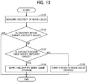
- FIG. 13 is a flowchart illustrating an example of the adjustment operation of the image forming apparatus 100a.
- FIG. 13 is a flowchart illustrating an example of a viscosity adjustment operation of the resin layer 30 by the image forming apparatus 100a as above-illustrated FIG. 10
- FIG. 13 illustrates an adjustment operation triggered by starting the viscosity adjustment operation of the resin layer 30 by the image forming apparatus 100a.
- a description of portions overlapping with FIG. 10 is omitted.
- a description of portions different from FIG. 10 is mainly described below.
- the image forming apparatus 100a measures the viscosity of the mixed liquid 15 stored in the mixed liquid storage 11 by the viscometer 4a, and outputs the measurement result to the controller 5a in step S131.
- the image forming apparatus 100a determines whether the measured viscosity of the mixed liquid 15 is within the target viscosity range in step S132.
- the targeted viscosity range is an example of a predetermined diameter range.
- step S132 determines that the viscosity is within the target viscosity range in step S132 (step S132, YES). If the image forming apparatus 100a determines that the viscosity is within the target viscosity range in step S132 (step S132, YES), the image forming apparatus 100a ends the viscosity adjustment operation. On the other hand, if the image forming apparatus 100a determines that the viscosity is not within the target viscosity range (step S132, NO), the image forming apparatus 100a determines whether the viscosity is above the target viscosity range in step S133.
- step S133 If the image forming apparatus 100 determines that the viscosity of the mixed liquid 15 is above the target viscosity range in step S106 (step S133, YES), the image forming apparatus 100 supplies the diluent to the mixed liquid storage 11 by the adjuster 6 to reduce the viscosity of the mixed liquid 15 and reduce the viscosity of the resin layer 30 in step S134.
- step S133 determines that the viscosity of the mixed liquid 15 is not above (below) the target viscosity range in step S133 (step S133, NO)
- the image forming apparatus 100 supplies the resin to the mixed liquid storage 11 by the adjuster 6 to increase the viscosity of the mixed liquid 15 and increase the viscosity of the resin layer 30 in step S135.
- the image forming apparatus 100a can adjust the viscosity of the resin layer 30.
- the viscometer 4a acquires viscosity (physical property) information of the mixed liquid 15 stored in the mixed liquid storage 11 in the image forming apparatus 100 according to the embodiments of the present disclosure.
- the above-described configuration can obtain effects same as described in the first embodiment.
- the image forming apparatuses 100 and 100a have been described as an example of the liquid discharge apparatus.
- the liquid discharge apparatus according to the present embodiment is not limited to an image forming apparatus.
- the above embodiments are applicable to any apparatus as long as the apparatus forms a pattern such as an image on the resin layer 30 applied (coated) onto the substrate 10 by a liquid discharge method.
- connection relation between the components is exemplified for the purpose of describing the technology of the embodiments of the present disclosure, and the connection relation to enable the functions of the present disclosure is not limited to the connection relation as described above.
- the above-described embodiments include a liquid discharge method.
- the liquid discharge method includes a liquid discharge method using the image forming apparatus 100 (liquid discharge apparatus).
- the image forming apparatus 100 (liquid discharge apparatus) conveys the substrate 10 in a predetermined conveyance direction by the conveyor 2.
- the image forming apparatus 100 drives the resin layer applier 1 to apply the resin layer 30 to the substrate 10.
- the liquid discharger discharges the droplets 31 to apply the droplets 31 onto the resin layer 30.
- the physical property information acquisition unit 54 acquires the physical property information of the resin layer 30.
- the adjuster 6 adjusts the physical properties of the resin layer 30 based on the acquired result (information) acquired by the physical property information acquisition unit 54.
- the controller controls the adjustment controller 55 to control the adjuster 6 to control the adjustment operation.
- Such a liquid discharge method can provide operational effects equivalent to the operational effects of the above-described image forming apparatuses 100.
- processing circuit or circuitry includes a programmed processor to execute each function by software, such as a processor implemented by an electronic circuit, and devices, such as an application specific integrated circuit (ASIC), a digital signal processor (DSP), a field programmable gate array (FPGA), and conventional circuit components arranged to perform the recited functions.
- ASIC application specific integrated circuit
- DSP digital signal processor
- FPGA field programmable gate array
- the present invention can be implemented in any convenient form, for example using dedicated hardware, or a mixture of dedicated hardware and software.
- the present invention may be implemented as computer software implemented by one or more networked processing apparatuses.
- the processing apparatuses include any suitably programmed apparatuses such as a general purpose computer, a personal digital assistant, a Wireless Application Protocol (WAP) or third-generation (3G)-compliant mobile telephone, and so on.
- WAP Wireless Application Protocol
- 3G third-generation
- the present invention can be implemented as software, each and every aspect of the present invention thus encompasses computer software implementable on a programmable device.
- the computer software can be provided to the programmable device using any conventional carrier medium (carrier means).
- the carrier medium includes a transient carrier medium such as an electrical, optical, microwave, acoustic or radio frequency signal carrying the computer code.
- transient medium is a Transmission Control Protocol/Internet Protocol (TCP/IP) signal carrying computer code over an IP network, such as the Internet.
- the carrier medium may also include a storage medium for storing processor readable code such as a floppy disk, a hard disk, a compact disc read-only memory (CD-ROM), a magnetic tape device, or a solid state memory device.
Landscapes
- Application Of Or Painting With Fluid Materials (AREA)
- Ink Jet (AREA)
- Ink Jet Recording Methods And Recording Media Thereof (AREA)
Abstract
Description
- An aspect of the present disclosure relates to a liquid discharge apparatus, an image forming apparatus, and a liquid discharge method.
- A liquid discharge apparatus applies (coats) a resin layer containing a polyvinyl chloride resin or the like containing a plasticizer on a substrate and discharges a liquid such as ink to apply droplets on the resin layer. Such liquid discharge apparatus includes an apparatus that forms an image on the substrate by a liquid discharge method to manufacture a sheet-like wallpaper.
- Further, the liquid discharging apparatus controls an application amount of an aggregating agent applied onto the substrate such as a paper to adjust a diameter of droplets discharged onto the resin layer containing the aggregating agent or the like (see
Japanese Unexamined Patent Application Publication No. 2010-184479 - However, the resin layer applied onto the substrate changes its physical properties such as viscosity according to a surrounding environment such as temperature and humidity. Therefore, a state of spread of the droplet applied onto the resin layer is changed according to the physical properties of the resin layer. Thus, a state of the droplets on the resin layer is not stable. Thus, quality of an image or the like formed on the resin layer may not be stable.
- It is an object of the embodiments of the present disclosure to stabilize the state of the droplet applied on the resin layer.
- In an aspect of this disclosure, a liquid discharge apparatus includes a conveyor configured to convey a substrate in a conveyance direction; a resin layer applier configured to apply a resin layer containing a resin onto the substrate conveyed by the conveyor, a liquid discharger configured to discharge a liquid onto the resin layer to apply a droplet onto the resin layer, an acquirer configured to acquire a physical property of the resin layer, an adjuster configured to adjust the physical property of the resin layer, and circuitry configured to control the adjuster to control the physical property of the resin layer according to the physical property acquired by the acquirer.
- In another aspect of this disclosure, a liquid discharge method includes conveying a substrate in a conveyance direction, applying a resin layer containing a resin onto the substrate; discharging a liquid onto the resin layer to apply a droplet onto the resin layer, acquiring a physical property of the resin layer; adjusting the physical property of the resin layer, and controlling the physical property of the resin layer according to the physical property acquired by the acquiring.
- The liquid discharge apparatus according to the embodiments of the present disclosure can stabilize the state of the droplet applied on the resin layer.
- A more complete appreciation of the disclosure and many of the attendant advantages and features thereof can be readily obtained and understood from the following detailed description with reference to the accompanying drawings, wherein:
-
FIG. 1 is a schematic side view of an overall configuration of an image forming apparatus according to a first embodiment of the present disclosure; -
FIG. 2 is a schematic side view of an example of configuration of a resin layer applier and an adjuster according to the first embodiment of the present disclosure; -
FIG. 3 is a block diagram illustrating an example of a hardware configuration of a controller; -
FIG. 4 is a block diagram illustrating a functional configuration example of the controller according to the first embodiment of the present disclosure; -
FIG. 5 is a side view of a droplet on a resin layer having a low viscosity; -
FIG. 6 is a side view of a droplet on a resin layer having a high viscosity; -
FIG. 7 is a schematic plan view of nozzle arrays in a nozzle surface of a head; -
FIG. 8 is a schematic plan view of the resin layer on which an adjustment pattern including droplets applied onto the resin layer is formed; -
FIG. 9 is a graph illustrating an example of the correspondence (correlation) between the diameter of the droplet applied on the resin layer and the viscosity of the resin layer; -
FIG. 10 is a flowchart illustrating an example of an adjustment operation of the image forming apparatus according to the first embodiment; -
FIG. 11 is a schematic cross-sectional side view of an example of the image forming apparatus according to a second embodiment of the present disclosure; -
FIG. 12 is a block diagram illustrating a functional configuration example of the controller according to the second embodiment of the present disclosure; and -
FIG. 13 is a flowchart illustrating an example of the adjustment operation of the image forming apparatus according to the second embodiment of the present disclosure. - The accompanying drawings are intended to depict embodiments of the present invention and should not be interpreted to limit the scope thereof. The accompanying drawings are not to be considered as drawn to scale unless explicitly noted. Also, identical or similar reference numerals designate identical or similar components throughout the several views.
- In describing embodiments illustrated in the drawings, specific terminology is employed for the sake of clarity. However, the disclosure of this specification is not intended to be limited to the specific terminology so selected and it is to be understood that each specific element includes all technical equivalents that have a similar function, operate in a similar manner, and achieve a similar result.
- Referring now to the drawings, embodiments of the present disclosure are described below. As used herein, the singular forms "a", "an", and "the" are intended to include the plural forms as well, unless the context clearly indicates otherwise.
- Embodiments of the present disclosure are described in detail with reference to drawings. In the drawings, the same components are denoted by the same reference numerals, and redundant description is omitted as appropriate.
- Further, the embodiments described below are some examples of a liquid discharge apparatus and an image forming apparatus for embodying the technical idea of the disclosure, and embodiments of the disclosure are not limited to the embodiments described below.
- The dimensions, materials, shapes, relative configurations and the like of the components described below are intended to be illustrative and not limiting of the scope of the invention, unless otherwise specified. The size, positional relationship, and the like of members illustrated in the drawings may be magnified for clarity of description.
- Hereinafter, an image forming apparatus serving as a liquid discharge apparatus according to a first embodiment of the present disclosure is described below. Note that image formation, recording, printing, and image printing in the terms of the embodiments are synonymous.
- Further, "liquid" discharged from a head is not particularly limited as long as the liquid has a viscosity and surface tension of degrees dischargeable from the head. Preferably, the viscosity of the liquid is not greater than 30 mPa·s under ordinary temperature and ordinary pressure or by heating or cooling.
- Examples of the liquid include a solution, a suspension, or an emulsion that contains, for example, a solvent, such as water or an organic solvent, a colorant, such as dye or pigment, a functional material, such as a polymerizable compound, a resin, or a surfactant, a biocompatible material, such as deoxyribonucleic acid (DNA), amino acid, protein, or calcium, or an edible material, such as a natural colorant. The liquid can be used, for example, in applications such as ink jet inks.
- The liquid discharger is a functional component that discharges and jets a liquid from a nozzle. Examples of an energy source for generating energy to discharge liquid include a piezoelectric actuator (a laminated piezoelectric element or a thin-film piezoelectric element), a thermal actuator that employs a thermoelectric conversion element, such as a thermal resistor, and an electrostatic actuator including a diaphragm and opposed electrodes.
-
FIG. 1 is a schematic side view of an overall configuration of animage forming apparatus 100 according to a first embodiment of the present disclosure. As illustrated inFIG. 1 , theimage forming apparatus 100 includes a resin layer applier 1, aconveyor 2, aliquid discharger 3, areader 4, acontroller 5, and anadjuster 6. - The
image forming apparatus 100 drives a resin layer applier 1 to apply a resin layer 30 (seeFIG. 8 ) to asubstrate 10. Theimage forming apparatus 100 further drives theliquid discharger 3 to discharges a liquid onto theresin layer 30 applied onto thesubstrate 10 to apply the liquid. Thecontroller 5 of theimage forming apparatus 100 controls theadjuster 6 to adjust physical properties of theresin layer 30 according to a reading result of thereader 4 that reads a pattern formed by the droplets applied on theresin layer 30. - For example, the
image forming apparatus 100 applies droplets onto theresin layer 30 applied on thesubstrate 10 to form an image to manufacture thesubstrate 10 as a wallpaper. Material of thesubstrate 10 is not particularly limited as long as the material has suitable mechanical strength, heat resistance, and the like as a substrate of a wallpaper. A common substrate such as a paper and nonwoven fabric may be used as a wallpaper. More specifically, a natural paper, a plastic film, a synthetic paper, non-woven fabric, cloth, wood, metal thin-film and the like may be used as thesubstrate 10. Thus, the material of thesubstrate 10 is selected according to an application of thesubstrate 10. - The resin layer applier 1 applies (coats) a
resin layer 30 containing resin to at least one surface of asmooth substrate 10 made of paper or non-woven fabric. Vinyl chloride resin, acrylic resin or the like can be used as the resin contained in theresin layer 30 to manufacture the wallpaper. Theresin layer 30 may contain a plasticizer or may contain a plasticizer and a heating foaming agent. Theresin layer 30 is applied (coated) on thesubstrate 10 in a state in which at least a vinyl chloride resin contains a plasticizer. - The
conveyor 2 includes aconveyance roller 21, apreheat drum 22, and aheating drum 23. Theconveyor 2 rotates each of theconveyance roller 21, thepreheat drum 22, and the heating drum 23.to convey thesubstrate 10 stretched around theconveyance roller 21, thepreheat drum 22, and theheating drum 23 along the predeterminedconveyance direction 20. Theconveyor 2 may further include other rollers or drums used for conveying thesubstrate 10. - The
conveyor 2 includes apreheat drum 22 and aheating drum 23 on a downstream of the resin layer applier 1 in theconveyance direction 20 as indicated by arrow inFIG. 1 . Each of thepreheat drum 22 and theheating drum 23 includes a heater inside thepreheat drum 22 and theheating drum 23. Each of thepreheat drum 22 and theheating drum 23 use the heater to heat thesubstrate 10 contacting an outer peripheral surface of thepreheat drum 22 and theheating drum 23 while conveying thesubstrate 10. - The
preheat drum 22 preheats thesubstrate 10 applied (coated) with theresin layer 30. Theheating drum 23 conveys a region of thesubstrate 10 applied (coated) with theresin layer 30 to a position facing theliquid discharger 3 while heating thesubstrate 10 to a substantially constant temperature. The resin heated by thepreheat drum 22 and theheating drum 23 gels so that theresin layer 30 is fixed on thesubstrate 10. - Although the
preheat drum 22 and theheating drum 23 are not essential components of theconveyor 2, theimage forming apparatus 100 preferably includes theheating drum 23 and the like to heat theresin layer 30 after applying (coating) theresin layer 30 on thesubstrate 10 from a viewpoint of stably fixing theresin layer 30 on thesubstrate 10. - The
image forming apparatus 100 includes theliquid discharger 3 in a downstream of the resin layer applier 1 in theconveyance direction 20. Theliquid discharger 3 discharge droplets onto theresin layer 30 of thesubstrate 10 conveyed by theheating drum 23 to apply droplets on theresin layer 30 after the resin layer applier 1 applies theresin layer 30 on thesubstrate 10. - The
liquid discharger 3 includes liquid discharge heads 3A, 3B, 3C and 3D. Hereinafter, the "liquid discharge head" is simply referred to as a "head". Theheads conveyance direction 20 to sequentially discharge a liquid toward the conveyedsubstrate 10. - Each of the
heads heads resin layer 30. - The liquid discharged from the
liquid discharger 3 is, for example, an oil-based ink having no curing reactivity as a liquid. The oil-based ink contains at least an oil-based component and a coloring agent, and may contain a binder resin if necessary. The oil-based ink preferably contains 80% by mass or more of an oil-based component having a boiling point of 200°C or higher. The oil-based component of the oil-based ink preferably contains ester oil as a main component. - The oil-based ink discharged from the
liquid discharger 3 contains an oil-based component and a coloring agent. From the viewpoint of maintaining good ink fixing properties after image formation, a content of the ester oil is preferably 30% by mass or more, more preferably 50% by mass or more and 90% by mass or less. The oil-based ink may contain 5% by mass or less of water. - The
reader 4 is an example of an acquirer to acquire physical property information of theresin layer 30. For example, thereader 4 is an in-line sensor that includes pixels such as a charge coupled device (CCD) and a complementary metal oxide semiconductor (CMOS) in a line shape. - The
reader 4 is disposed such that pixels are arrayed in a direction substantially orthogonal to theconveyance direction 20. Thereader 4 reads the pattern formed on theresin layer 30 on thesubstrate 10 conveyed along theconveyance direction 20 to shoot a two-dimensional pattern. However, thereader 4 is not limited to the in-line sensor, and may include a two-dimensional imaging element in which pixels such as the CCD and the CMOS are two dimensionally arrayed. - When the
reader 4 reads the physical properties of theresin layer 30, theimage forming apparatus 100 first drives theliquid discharger 3 to form a predetermined adjustment pattern (predetermined pattern) on theresin layer 30 to acquire the physical property information of theresin layer 30. Then, thereader 4 reads the adjustment pattern formed on theresin layer 30. Thereader 4 is disposed downstream of theliquid discharger 3 in theconveyance direction 20. - The adjustment pattern is, for example, a dot pattern formed by droplets. The physical property of the
resin layer 30 to be acquired is viscosity, for example. The droplets applied on theresin layer 30 spread differently according to the viscosity of theresin layer 30. Thus, thereader 4 reads an image of a dot pattern formed by the droplets and outputs a read image to thecontroller 5. In the following description, the viscosity of theresin layer 30 is an example of the physical properties of theresin layer 30. - The
controller 5 controls a liquid discharge operation by theliquid discharger 3, a conveyance operation of thesubstrate 10 by theconveyor 2, and an adjustment operation of theadjuster 6 based on viscosity information of theresin layer 30. -
FIG. 2 is a schematic side view of an example of configuration of the resin layer applier 1 and theadjuster 6 according to the first embodiment of the present disclosure. - The resin layer applier 1 includes a mixed
liquid storage 11, astirrer 12, anapplication roller 13, and ablade 14. A resin layer applier 1 coats thesubstrate 10 with theresin layer 30 formed from amixed liquid 15 of a resin and a diluent that dilutes the mixed liquid to change a rate of the resin contained in theresin layer 30. Examples of the diluent include water, thinner, and organic solvent. - The mixed
liquid storage 11 is a container to store themixed liquid 15. A vertically upper part of the mixedliquid storage 11 is open to the atmosphere. - The
stirrer 12 includes blades rotatably disposed inside the mixedliquid storage 11. Thestirrer 12 rotates and stirs themixed liquid 15 stored in the mixedliquid storage 11. Thus, thestirrer 12 stirs themixed liquid 15 so that the ratio of the resin to the diluent is substantially constant over the entiremixed liquid 15. - The
substrate 10 is stretched around an outer peripheral surface of theapplication roller 13. Theapplication roller 13 is immersible a part of thesubstrate 10 in themixed liquid 15 through a vertically upper part of the mixedliquid storage 11 opening to the atmosphere. Thesubstrate 10 is stretched around theapplication roller 13 as described above. Themixed liquid 15 is adhered to an immersed region of thesubstrate 10 immersed in themixed liquid 15. - The
blade 14 is disposed on a downstream of the immersed region of thesubstrate 10 in theconveyance direction 20. A leading edge of theblade 14 is brought into contact with the surface of thesubstrate 10 conveyed along theconveyance direction 20. Thus, theblade 14 regulates a thickness of themixed liquid 15 adhered onto the surface of thesubstrate 10 so that the thickness of themixed liquid 15 becomes substantially constant. As a result, themixed liquid 15 is applied onto the surface of thesubstrate 10 at a substantially constant thickness. Thus, theresin layer 30 made of themixed liquid 15 is applied (coated) on thesubstrate 10. - Examples of methods of applying the
resin layer 30 onto thesubstrate 10 by the resin layer applier 1 includes, but not limited to, a nozzle coating method, a die coating method, a lip coating method, a comma coating method, a gravure coating method, a rotary screen coating method, a reverse roll coating method, and the like in addition to the methods described above. - The
adjuster 6 includes adiluent tank 61, adiluent switch valve 62, adiluent supply nozzle 63, aresin tank 64, aresin switch valve 65, and aresin supply nozzle 66. Theadjuster 6 supplies at least one of a resin or a diluent to the mixedliquid storage 11 to adjust the physical properties of theresin layer 30 applied to thesubstrate 10. Any liquid may be used as the diluent as long as the liquid is dilutable viscosity and other physical properties of themixed liquid 15. - The
diluent tank 61 is a container to store a diluent. One end of thediluent supply nozzle 63 is connected to thediluent tank 61 via thediluent switch valve 62. Thediluent switch valve 62 is an electromagnetic valve switchable in response to a control signal from thecontroller 5. Another end of thediluent supply nozzle 63 is coupled (connected) to the mixedliquid storage 11. Thediluent tank 61 and the mixedliquid storage 11 communicate with each other through adiluent supply nozzle 63. - The
diluent tank 61 is disposed such that a liquid level of the diluent stored in thediluent tank 61 is higher than a liquid level of themixed liquid 15 in the mixedliquid storage 11 in a vertical direction. Therefore, the diluent in thediluent tank 61 flows toward the mixedliquid storage 11 by the water head pressure and is supplied to the mixedliquid storage 11 in response to an opening of thediluent switch valve 62. Supply of the diluent to the mixedliquid storage 11 is stopped in response to a closing of thediluent switch valve 62. - The
resin tank 64 is a container to store a liquid resin. One end of theresin supply nozzle 66 is coupled (connected) to theresin tank 64 via theresin switch valve 65. Theresin switch valve 65 is an electromagnetic valve switchable in response to a control signal from thecontroller 5. Another end of theresin supply nozzle 66 is coupled (connected) to the mixedliquid storage 11. Theresin tank 64 and the mixedliquid storage 11 communicate with each other through aresin supply nozzle 66. - The
resin tank 64 is disposed such that a liquid level of the diluent stored in thediluent tank 61 is higher than a liquid level of themixed liquid 15 in the mixedliquid storage 11 in a vertical direction. Therefore, the resin in theresin tank 64 flows toward the mixedliquid storage 11 by the water head pressure and is supplied to the mixedliquid storage 11 in response to an opening of theresin switch valve 65. When theresin switch valve 65 is closed, the supply of the resin to the mixedliquid storage 11 is stopped. - The supply of the diluent to the mixed
liquid storage 11 increase a rate of the diluent in themixed liquid 15 in the mixedliquid storage 11. Thus, the viscosity of the mixed liquid decreases, and the viscosity of theresin layer 30 formed by themixed liquid 15 decreases. The supply of the resin to the mixedliquid storage 11 increase a rate of the resin in themixed liquid 15 in the mixedliquid storage 11. Thus, the viscosity of themixed liquid 15 increases, and the viscosity of theresin layer 30 by themixed liquid 15 increases. Therefore, theadjuster 6 supplies at least one of the diluent and the resin to the mixedliquid storage 11 or stops the supply of at least one of the diluent and the resin to the mixedliquid storage 11 in response to a control signal from thecontroller 5. Thus, theadjuster 6 is adjustable the viscosity of theresin layer 30. - The
image forming apparatus 100 according to the first embodiment as described above illustrates a configuration in which a head pressure is used to supply the diluent and the resin to thesubstrate 10. However, theimage forming apparatus 100 according to the first embodiment is not limited to the embodiment as described above, and theimage forming apparatus 100 may use a pump or the like to supply the diluent and the resin to thesubstrate 10. - A configuration of the
adjuster 6 and a method to adjust the physical properties of the liquid by theadjuster 6 are not limited to the configuration and the method as described with reference toFIG. 2 . Any adjustment method may be used as long as the physical properties of the liquid are adjustable. -
FIG. 3 is a block diagram illustrating an example of a hardware configuration of thecontroller 5. - The
controller 5 includes a central processing unit (CPU 101), a read only memory (ROM 102), a random-access memory (RAM 103), a hard disk drive (HDD) / solid state drive (SSD) 104, and an interface (I/F 105). The hard disk drive (HDD) / solid state drive (SSD) 104 is simply referred to as a "HDD/SSD 104". The above-described elements are electrically connected (coupled) via a system bus B. The resin layer applier 1, theconveyor 2, theliquid discharger 3, thereader 4, theadjuster 6, and the like are coupled (connected) to the system bus B. - The
CPU 101 is a processor that uses theRAM 103 as a work area and executes programs stored in theROM 102. The HDD/SSD 104 is used as storage and stores preset setting values. TheCPU 101 may read information stored in the HDD/SSD 104 and use the information to execute a program. The I/F 105 is an interface to communicatively connecting thecontroller 5 and an external device 7 such as a client personal computer (PC). -
FIG. 4 is a block diagram illustrating a functional configuration example of thecontroller 5 according to the first embodiment of the present disclosure. - The
controller 5 includes a resinlayer application controller 51, aconveyance controller 52, adischarge controller 53, a physical propertyinformation acquisition unit 54, anadjustment controller 55, and an input-output unit 56. TheCPU 101 illustrated inFIG. 3 executes a predetermined program or the like to realize the above-described functions. Thecontroller 5 may include functions other than the functions as described above. - The resin
layer application controller 51 controls an operation of the resin layer applier 1. Theconveyance controller 52 controls an operation of theconveyor 2. Thedischarge controller 53 controls an operation of theliquid discharger 3. Theadjustment controller 55 controls an operation of theadjuster 6. - The physical property
information acquisition unit 54 performs image processing on a read image input from thereader 4. The physical propertyinformation acquisition unit 54 detects a diameter of the droplet included in the adjustment pattern in the read image. Then, the physical propertyinformation acquisition unit 54 refers to a predetermined correspondence (correlation) between the diameter of the droplet and the viscosity of theresin layer 30 to acquire the viscosity information of theresin layer 30 based on the detected diameter of the droplet. The physical propertyinformation acquisition unit 54 outputs the physical property information to theadjustment controller 55. Thereader 4 may include functions of the physical propertyinformation acquisition unit 54. - The
adjustment controller 55 outputs a control signal to control opening and closing of thediluent switch valve 62 and theresin switch valve 65 in accordance with the property information of the resin layer input from the physical propertyinformation acquisition unit 54. Theadjustment controller 55 controls theadjuster 6 to control the supply of each of the diluent and the resin to the mixedliquid storage 11 to adjust a viscosity of theresin layer 30. -
FIG. 5 is a side view of adroplet 31 on aresin layer 30a applied (coated) on thesubstrate 10. Theresin layer 30a has a low viscosity. InFIG. 5 , thedroplet 31 is applied on theresin layer 30a applied (coated) on thesubstrate 10. -
FIG. 6 is a side view of adroplet 31 on aresin layer 30b applied (coated) on thesubstrate 10. Theresin layer 30b has a viscosity higher than the viscosity of theresin layer 30a. InFIG. 6 , thedroplet 31 is applied on theresin layer 30b applied (coated) on thesubstrate 10. - Since the viscosity of the
resin layer 30a is higher than the viscosity of theresin layer 30b so that a wettability (hydrophilicity) of theresin layer 30a is higher than a wettability (hydrophilicity) of theresin layer 30b. Thus, a wet-spreadability of thedroplets 31 on theresin layer 30a is larger than the wet-spreadability of thedroplets 31 on theresin layer 30b. As a result, a diameter Da of thedroplet 31 on theresin layer 30a is larger than a diameter Db of thedroplet 31 on theresin layer 30b. -
FIGS. 7 and8 illustrate an example of the adjustment pattern. -
FIG. 7 is a schematic plan view of nozzle arrays 3Aa to 3Ad in a nozzle surface of thehead 3A. -
FIG. 7 illustrates the nozzle arrays 3Aa to 3Ad formed in the nozzle surface of thehead 3A. Each of the nozzle arrays 3Aa to 3Ad includes multiple nozzles. -
FIG. 8 is a schematic plan view of theresin layer 30 on which an adjustment pattern is formed. Thehead 3A discharges (applies)droplets 31 from the nozzles on theresin layer 30 to form the adjustment pattern on theresin layer 30. -
FIG. 8 is a plan view of theresin layer 30 viewed from an application surface of thedroplets 31 of theresin layer 30 onto which thedroplets 31 are applied. Theresin layer 30 is applied onto thesubstrate 10 as described above. - As illustrated in
FIG. 7 , thehead 3A includes nozzle arrays 3Aa to 3Ad. Each of the nozzle arrays 3Aa to 3Ad includes the multiple nozzles from which thedroplets 31 are discharged. The multiple nozzles are arrayed in each of the nozzle arrays 3Aa to 3Ad in a direction orthogonal to theconveyance direction 20. Although thehead 3A is illustrated as an example here, theheads 3A to 3D in theliquid discharger 3 have the same configuration. Thus, thehead 3A inFIG. 7 may be any one of theheads 3A to 3D. - As illustrated in
FIG. 8 , theadjustment pattern 32 includes apattern 32a, apattern 32b, apattern 32c, and apattern 32d. Thepattern 32a is formed bydroplets 31 discharged from the nozzle array 3Aa. Thepattern 32b is formed bydroplets 31 discharged from the nozzle array 3Ab. Thepattern 32c is formed bydroplets 31 discharged from the nozzle array 3Ac. Thepattern 32d is formed bydroplets 31 discharged from the nozzle array 3Ad. - The
adjustment pattern 32 is a dot pattern applied on theresin layer 30 at intervals such that thedroplets 31 discharged from the nozzles included in each of the nozzle arrays 3Aa to 3Ad do not coincide and unite with each other. - The
reader 4 reads theadjustment pattern 32 and outputs the read image to thecontroller 5. The physical propertyinformation acquisition unit 54 of thecontroller 5 performs image processing on the read image of theadjustment pattern 32 and detects the diameter of thedroplet 31 corresponding to one dot in the read image. - The physical property
information acquisition unit 54 may detect diameter information of apredetermined droplet 31 among themultiples droplets 31 included in theadjustment pattern 32. The physical propertyinformation acquisition unit 54 may also detect an average value or the like of the diameter information of themultiple droplets 31 as the diameter information of thedroplets 31. Thus, the physical propertyinformation acquisition unit 54 detects a diameter of at least one of themultiple droplets 31 in theadjustment pattern 32. -
FIG. 9 is a graph illustrating an example of the correspondence (correlation) between the diameter of thedroplet 31 applied on theresin layer 30 and the viscosity of theresin layer 30. InFIG. 9 , a horizontal axis represents the viscosity of theresin layer 30, and a vertical axis represents the diameter of thedroplet 31. - As the viscosity of the
resin layer 30 increases, the wettability of theresin layer 30 decreases, so that the wet-spreadability of thedroplets 31 applied on theresin layer 30 decreases, and the diameter of thedroplets 31 decreases. - The correspondence (correlation) illustrated in
FIG. 9 is stored in advance in the HDD/SSD 104 or the like as a correspondence table. The physical propertyinformation acquisition unit 54 refers to the correspondence table stored in the HDD/SSD 104 based on the diameter information of the detecteddroplet 31 to acquire the viscosity information of theresin layer 30. -
FIG. 10 is a flowchart illustrating an example of a viscosity adjustment operation of theresin layer 30 by theimage forming apparatus 100. -
FIG. 10 illustrates an adjustment operation triggered by starting the viscosity adjustment operation of theresin layer 30 by theimage forming apparatus 100. A trigger of the viscosity adjustment operation may be automatically triggered at a predetermined timing. A trigger of the viscosity adjustment operation may also be triggered in response to an operation input signal from the user of theimage forming apparatus 100 to theimage forming apparatus 100. - The
image forming apparatus 100 can appropriately perform the operation illustrated inFIG. 10 according to a usage, a usage environment, or the like of theimage forming apparatus 100. For example, theimage forming apparatus 100 may perform the operation illustrated inFIG. 10 each time theimage forming apparatus 100 performs image formation. Alternatively, theimage forming apparatus 100 may also perform the operation illustrated inFIG. 10 once in a predetermined timing such as a start-up time of theimage forming apparatus 100. - First, the
image forming apparatus 100 applies (coats) theresin layer 30 on thesubstrate 10 by the resin layer applier 1 in step S101. - Subsequently, the
liquid discharger 3 of theimage forming apparatus 100 discharges thedroplets 31 while thesubstrate 10 is conveyed by theconveyor 2 in step S102. Theimage forming apparatus 100 applies thedroplets 31 onto theresin layer 30 applied (coated) onto thesubstrate 10 to form apredetermined adjustment pattern 32 on theresin layer 30. Theadjustment pattern 32 is, for example, a dot pattern. - In step S103, the
reader 4 of theimage forming apparatus 100 reads theadjustment pattern 32 formed on theresin layer 30. - Subsequently, the
controller 5 of theimage forming apparatus 100 performs image processing on the read image of theadjustment pattern 32 by thereader 4 in step S104. Theimage forming apparatus 100 detects the diameter of thedroplet 31 included in theadjustment pattern 32. - Subsequently, the
image forming apparatus 100 determines whether the diameter of the detecteddroplet 31 is within a target diameter range in step S105. The target diameter range is an example of a predetermined diameter range. - If the
image forming apparatus 100 determines that the diameter of thedroplet 31 is within the target diameter range in step S105 (step S105, YES), theimage forming apparatus 100 ends the operation. On the other hand, if theimage forming apparatus 100 determines that the diameter of thedroplet 31 is not within the target diameter range (step S105, NO), theimage forming apparatus 100 determines whether the diameter of thedroplet 31 is below the target diameter range in step S106. - If the
image forming apparatus 100 determines that the diameter of thedroplet 31 is below the target diameter range in step S106 (step S106, YES), theimage forming apparatus 100 supplies the diluent to the mixedliquid storage 11 by theadjuster 6 to reduce the viscosity of themixed liquid 15 and reduce the viscosity of theresin layer 30 in step S107. - If the
image forming apparatus 100 determines that the diameter of thedroplet 31 is not below (above) the target diameter range in step S106 (step S106, NO), theimage forming apparatus 100 supplies the resin to the mixedliquid storage 11 by theadjuster 6 to increase the viscosity of themixed liquid 15 and increase the viscosity of theresin layer 30 in step S108. - In the above way, the
image forming apparatus 100 can adjust the viscosity of theresin layer 30. - Next, an operational effect of the
image forming apparatus 100 is described below. - A sheet-like wallpaper with excellent design is used for the inner walls and ceilings of buildings.
- To produce the wallpaper, a resin layer made of a polyvinyl chloride resin containing a plasticizer is applied (coated) on a noncombustible substrate such as a base paper or a non-woven fabric. Then an image forming apparatus forms an image on the resin layer by a liquid discharge method.
- However, a wettability of the
resin layer 30 changes due to an influence of temperature and humidity around an image forming apparatus.in a conventional image forming apparatus. When the wettability of the resin layer is high, the droplets on the resin layer are easy to spread. When the wettability of the resin layer is low, the droplets on the resin layer are not easily spread. As a result, a coverage of the droplets on the substrate differs according to temperature and humidity. In some cases, quality of a formed image varies and becomes unstable. - To solve the above-described problem, an operator may perform an operation such as adding a diluent to the resin layer while visually confirming quality of image formed on the substrate. However, the above operation increases work man-hours and may cause problems such as variance in the image quality depending on the operator who performs the work.
- An
image forming apparatus 100 according to the first embodiment includes theconveyor 2 to convey thesubstrate 10 in theconveyance direction 20, a resin layer applier 1 to apply theresin layer 30 containing a resin to thesubstrate 10, and aliquid discharger 3 to discharge a liquid to applydroplets 31 on theresin layer 30. Theimage forming apparatus 100 includes the reader 4 (er), theadjuster 6, and thecontroller 5. The reader 4 (acquirer) acquires the physical property information of theresin layer 30. Theadjuster 6 adjusts the viscosity (physical property) of theresin layer 30. Thecontroller 5 controls an adjustment operation of theadjuster 6. - For example, the resin layer applier 1 applies the
mixed liquid 15 onto thesubstrate 10 to apply theresin layer 30 onto thesubstrate 10. Themixed liquid 15 is a mixture of a resin and a diluent. The diluent dilutes the mixed liquid to change a rate of the resin contained in theresin layer 30. Themixed liquid 15 is stored in the mixedliquid storage 11. Theadjuster 6 supplies at least one of a resin and a diluent to a mixedliquid storage 11 to adjust the viscosity of theresin layer 30. - The
liquid discharger 3 applies thedroplets 31 onto theresin layer 30 to form the adjustment pattern 32 (predetermined pattern). Thereader 4 acquires the viscosity information of theresin layer 30 based on theadjustment pattern 32 formed on theresin layer 30. - With the above-described configuration, the
image forming apparatus 100 uses theadjuster 6 to adjust the viscosity of theresin layer 30 based on the viscosity information of theresin layer 30 acquired from the reading result of theadjustment pattern 32 read by thereader 4 even when the viscosity of theresin layer 30 changes due to changes in temperature and humidity around theimage forming apparatus 100. As a result, the image forming apparatus 100 (liquid discharge apparatus) can reduce a change in the viscosity of theresin layer 30 and stabilize a state of thedroplets 31 applied on theresin layer 30. - The
reader 4 in theimage forming apparatus 100 according to the first embodiment acquires the viscosity information of theresin layer 30 based on the diameter of thedroplet 31 included in theadjustment pattern 32 formed on theresin layer 30. Thereader 4 is disposed in a downstream of theliquid discharger 3 in theconveyance direction 20 so that thereader 4 acquires the viscosity information in a downstream of theliquid discharger 3 in theconveyance direction 20. - For example, the
adjuster 6 supplies a resin to the mixedliquid storage 11 to adjust the viscosity of theresin layer 30 when the diameter of thedroplet 31 is above the target diameter range (predetermined diameter range). Further, theadjuster 6 supplies a diluent to the mixedliquid storage 11 to adjust the viscosity of theresin layer 30 when the diameter of thedroplet 31 is below the target diameter range (predetermined diameter range). - The
reader 4 acquires the viscosity information of theresin layer 30 from the diameter of thedroplet 31 applied (coated) on theresin layer 30 by theliquid discharger 3. Thus, theimage forming apparatus 100 can further accurately acquire a change in the viscosity of theresin layer 30 that affects a state of thedroplets 31. As a result, the image forming apparatus 100 (liquid discharge apparatus) can reduce a change in the viscosity of theresin layer 30 and stabilize a state of thedroplets 31 applied on theresin layer 30. - In the
image forming apparatus 100 according to the first embodiment, theresin layer 30 contains polyvinyl chloride. As a result, theimage forming apparatus 100 can easily apply (coats) theresin layer 30 onto thesubstrate 10 so that theresin layer 30 is obtainable good weather resistance, water resistance, or strength. - The liquid discharged from the
liquid discharger 3 is an oil-based ink in the first embodiment of the present disclosure. Thus, theimage forming apparatus 100 applies the oil-based ink to theresin layer 30 in a heated state to form an image. Therefore, theimage forming apparatus 100 can apply a liquid that produces good image quality without forming a special receiving layer on thesubstrate 10. - In the
image forming apparatus 100 according to the first embodiment, the viscosity of theresin layer 30 is used as an example of the physical property of theresin layer 30. However, the physical property of theresin layer 30 is not limited the viscosity and may be any other physical properties. Theimage forming apparatus 100 acquires information of theresin layer 30 such as the surface tension and the wettability of theresin layer 30. Theadjuster 6 of theimage forming apparatus 100 may also adjust the surface tension and the wettability of theresin layer 30 based on the acquired result (information) on the surface tension and the wettability of theresin layer 30. In the above case as well, theimage forming apparatus 100 can reduce changes in surface tension and wettability of theresin layer 30 and stabilize the state ofdroplets 31 applied on theresin layer 30. - A dot pattern is illustrated as an example of the
adjustment pattern 32, and a method that acquires the viscosity information of the liquid from the diameter of a dot (droplet 31) is illustrated as an example of the physical property information in theimage forming apparatus 100 according to the first embodiment. However, theadjustment pattern 32 and the physical property information are not limited to the examples as described above. - The
image forming apparatus 100 may appropriately changes theadjustment pattern 32 or information detected from theadjustment pattern 32 according to usage or usage information of theimage forming apparatus 100 as long as thereader 4 and the physical propertyinformation acquisition unit 54 can acquire the physical property information of the liquid. - When the
image forming apparatus 100 can monitor characteristics of themixed liquid 15 with some characteristic values, theimage forming apparatus 100 may only control the characteristic values without detecting the diameter of thedroplet 31 to stabilize the image quality after adjusting the physical properties based on the diameter of theinitial droplet 31. Examples of the characteristic values include a load applied to thestirrer 12 and the physical properties of themixed liquid 15. Here, the higher the viscosity is, the larger the load applied to thestirrer 12 becomes. When the physical property of themixed liquid 15 is used as a characteristic value, theimage forming apparatus 100 may include a sensor to detect the physical property of themixed liquid 15. - Next, an
image forming apparatus 100a according to a second embodiment of the present disclosure is described below. The same components as those of the first embodiment are denoted by the same reference numerals, and redundant description thereof will be appropriately omitted. -
FIG. 11 is a schematic cross-sectional side view of an example of theimage forming apparatus 100a according to the second embodiment of the present disclosure. As illustrated inFIG. 11 , theimage forming apparatus 100a includes aviscometer 4a and acontroller 5a. - The
viscometer 4a is an example of an acquirer to acquire the viscosity information of themixed liquid 15 stored in the mixedliquid storage 11. The method of measuring the viscosity by theviscometer 4a is not particularly limited. Various measurement methods such as a capillary viscometer, a falling ball viscometer or a rotational viscometer may be used to measure the viscosity of themixed liquid 15 in the mixedliquid storage 11. - A lower portion of the
viscometer 4a is in a state of being immersed in themixed liquid 15 stored in the mixedliquid storage 11. Theviscometer 4a outputs a measurement result of the viscosity to thecontroller 5a. -
FIG. 12 is a block diagram illustrating an example of the functional configuration of thecontroller 5a. As illustrated inFIG. 12 , thecontroller 5a includes a physical propertyinformation acquisition unit 54a. The physical propertyinformation acquisition unit 54a inputs the measurement result of the viscosity from theviscometer 4a to acquire the viscosity information of theresin layer 30. Theviscometer 4a measures the viscosity of themixed liquid 15 as described above. - The elements illustrated in
FIG. 12 such as thecontroller 5a, the physical propertyinformation acquisition unit 54a, the resin layer applier 1, theconveyor 2, theliquid discharger 3, and theadjuster 6 have a similar function, operate in a similar manner, and achieve a similar result with thecontroller 5, the physical propertyinformation acquisition unit 54, the resin layer applier 1, theconveyor 2, theliquid discharger 3, and theadjuster 6 as illustrated inFIG. 4 , respectively. -
FIG. 13 is a flowchart illustrating an example of the adjustment operation of theimage forming apparatus 100a. -
FIG. 13 is a flowchart illustrating an example of a viscosity adjustment operation of theresin layer 30 by theimage forming apparatus 100a as above-illustratedFIG. 10 -
FIG. 13 illustrates an adjustment operation triggered by starting the viscosity adjustment operation of theresin layer 30 by theimage forming apparatus 100a. Here, a description of portions overlapping withFIG. 10 is omitted. Conversely, a description of portions different fromFIG. 10 is mainly described below. - First, the
image forming apparatus 100a measures the viscosity of themixed liquid 15 stored in the mixedliquid storage 11 by theviscometer 4a, and outputs the measurement result to thecontroller 5a in step S131. - Next, the
image forming apparatus 100a determines whether the measured viscosity of themixed liquid 15 is within the target viscosity range in step S132. The targeted viscosity range is an example of a predetermined diameter range. - If the
image forming apparatus 100a determines that the viscosity is within the target viscosity range in step S132 (step S132, YES), theimage forming apparatus 100a ends the viscosity adjustment operation. On the other hand, if theimage forming apparatus 100a determines that the viscosity is not within the target viscosity range (step S132, NO), theimage forming apparatus 100a determines whether the viscosity is above the target viscosity range in step S133. - If the
image forming apparatus 100 determines that the viscosity of themixed liquid 15 is above the target viscosity range in step S106 (step S133, YES), theimage forming apparatus 100 supplies the diluent to the mixedliquid storage 11 by theadjuster 6 to reduce the viscosity of themixed liquid 15 and reduce the viscosity of theresin layer 30 in step S134. - If the
image forming apparatus 100 determines that the viscosity of themixed liquid 15 is not above (below) the target viscosity range in step S133 (step S133, NO), theimage forming apparatus 100 supplies the resin to the mixedliquid storage 11 by theadjuster 6 to increase the viscosity of themixed liquid 15 and increase the viscosity of theresin layer 30 in step S135. - In the above way, the
image forming apparatus 100a can adjust the viscosity of theresin layer 30. - As described above, the
viscometer 4a (er) acquires viscosity (physical property) information of themixed liquid 15 stored in the mixedliquid storage 11 in theimage forming apparatus 100 according to the embodiments of the present disclosure. The above-described configuration can obtain effects same as described in the first embodiment. - Although some embodiments have been described above, embodiments of the present disclosure are not limited to the above-described embodiments specifically disclosed. Various modifications and changes are possible without departing from the scope of the claims.
- In the above-described embodiment, the
image forming apparatuses resin layer 30 applied (coated) onto thesubstrate 10 by a liquid discharge method. - The numbers such as ordinal number and quantity used in the description of the above embodiments are all illustrative for the purpose of describing the technology of the embodiments of the present disclosure, and the embodiments of the present disclosure are not limited to the illustrative numbers. Further, a connection relation between the components is exemplified for the purpose of describing the technology of the embodiments of the present disclosure, and the connection relation to enable the functions of the present disclosure is not limited to the connection relation as described above.
- Further, the above-described embodiments include a liquid discharge method. For example, the liquid discharge method includes a liquid discharge method using the image forming apparatus 100 (liquid discharge apparatus). The image forming apparatus 100 (liquid discharge apparatus) conveys the
substrate 10 in a predetermined conveyance direction by theconveyor 2. Theimage forming apparatus 100 drives the resin layer applier 1 to apply theresin layer 30 to thesubstrate 10. The liquid discharger discharges thedroplets 31 to apply thedroplets 31 onto theresin layer 30. The physical propertyinformation acquisition unit 54 acquires the physical property information of theresin layer 30. Theadjuster 6 adjusts the physical properties of theresin layer 30 based on the acquired result (information) acquired by the physical propertyinformation acquisition unit 54. The controller controls theadjustment controller 55 to control theadjuster 6 to control the adjustment operation. Such a liquid discharge method can provide operational effects equivalent to the operational effects of the above-describedimage forming apparatuses 100. - Each function of the embodiments described above such as the
controller 5 can be implemented by one processing circuit or a plurality of processing circuits. Here, the term "processing circuit or circuitry" in the present specification includes a programmed processor to execute each function by software, such as a processor implemented by an electronic circuit, and devices, such as an application specific integrated circuit (ASIC), a digital signal processor (DSP), a field programmable gate array (FPGA), and conventional circuit components arranged to perform the recited functions. - Any one of the above-described operations may be performed in various other ways, for example, in an order different from the one described above.
- The present invention can be implemented in any convenient form, for example using dedicated hardware, or a mixture of dedicated hardware and software. The present invention may be implemented as computer software implemented by one or more networked processing apparatuses. The processing apparatuses include any suitably programmed apparatuses such as a general purpose computer, a personal digital assistant, a Wireless Application Protocol (WAP) or third-generation (3G)-compliant mobile telephone, and so on.
- Since the present invention can be implemented as software, each and every aspect of the present invention thus encompasses computer software implementable on a programmable device. The computer software can be provided to the programmable device using any conventional carrier medium (carrier means). The carrier medium includes a transient carrier medium such as an electrical, optical, microwave, acoustic or radio frequency signal carrying the computer code.
- An example of such a transient medium is a Transmission Control Protocol/Internet Protocol (TCP/IP) signal carrying computer code over an IP network, such as the Internet. The carrier medium may also include a storage medium for storing processor readable code such as a floppy disk, a hard disk, a compact disc read-only memory (CD-ROM), a magnetic tape device, or a solid state memory device.
Claims (14)
- A liquid discharge apparatus comprising:a conveyor (2) configured to convey a substrate (10) in a conveyance direction;a resin layer applier (1) configured to apply a resin layer (30) containing a resin onto the substrate (10) conveyed by the conveyor (2);a liquid discharger (3) configured to discharge a liquid onto the resin layer (30) to apply a droplet (31) onto the resin layer (30);an acquirer (4, 4a) configured to acquire a physical property of the resin layer (30);an adjuster (6) configured to adjust the physical property of the resin layer (30); andcircuitry (5) configured to control the adjuster (6) to control the physical property of the resin layer (30) according to the physical property acquired by the acquirer (4, 4a).
- The liquid discharge apparatus according to claim 1,wherein the liquid discharger (3) applies the droplet (31) onto the resin layer (30) to form a pattern on the resin layer (30), andthe acquirer (4, 4a) acquires the physical property of the resin layer (30), and the physical property of the resin layer (30) is based on the pattern formed on the resin layer (30).
- The liquid discharge apparatus according to claim 2,wherein the acquirer (4, 4a) comprises a reader (4) configured to read an image of the pattern, andthe circuitry (5) is further configured to detect a diameter of the droplet in the image of the pattern on the resin layer (30) to acquire the physical property.
- The liquid discharge apparatus according to claim 3,wherein the resin layer applier (1) comprises a mixed liquid storage (11) configured to store a mixed liquid containing the resin and a diluent that dilutes the mixed liquid to change a rate of the resin in the resin layer (30),the resin layer applier (1) applies the mixed liquid (15) onto the substrate (10) to apply the resin layer (30) onto the substrate (10), andthe adjuster (6) supplies at least one of the resin and the diluent to the mixed liquid storage (11) to adjust the physical property of the resin layer (30).
- The liquid discharge apparatus according to claim 4,wherein the adjuster (6) supplies the resin to the mixed liquid storage (11) if the diameter of the droplet is above a target diameter range; andthe adjuster (6) supplies the diluent to the mixed liquid storage (11) if the diameter of the droplet is below the target diameter range.
- The liquid discharge apparatus according to claim 1,wherein the resin layer applier (1) comprises a mixed liquid storage (11) configured to store a mixed liquid containing the resin and a diluent that dilutes the mixed liquid to change a rate of the resin in the resin layer (30),the resin layer applier (1) applies the mixed liquid (15) onto the substrate (10) to apply the resin layer (30) onto the substrate (10), andthe acquirer (4, 4a) comprises a viscometer (4a) configured to measure a viscosity of the mixed liquid in the mixed liquid storage (11) to acquire the viscosity of the mixed liquid (15) as the physical property.
- The liquid discharge apparatus according to claim 6,wherein the adjuster (6) supplies the resin to the mixed liquid storage (11) if the viscosity of the mixed liquid (15) is below a target viscosity range; andthe adjuster (6) supplies the diluent to the mixed liquid storage (11) ) if the viscosity of the mixed liquid (15) is above the target viscosity range.
- The liquid discharge apparatus according to any one of claims 1 to 7,
wherein the resin of the resin layer (30) contains a polyvinyl chloride resin. - The liquid discharge apparatus according to any one of claims 1 to 8,
wherein the liquid is an oil-based ink. - The liquid discharge apparatus according to any one of claims 1 to 9,
wherein the physical property of the resin layer (30) includes viscosity of the resin layer (30). - The liquid discharge apparatus according to any one of claims 1 to 10,
wherein the physical property of the resin layer (30) includes a surface tension of the resin layer (30). - The liquid discharge apparatus according to any one of claims 1 to 11,
wherein the physical property of the resin layer (30) includes a wettability of the resin layer (30). - An image forming apparatus comprising the liquid discharge apparatus according to any one of claims 1 to 12.
- A liquid discharge method comprising:conveying a substrate (10) in a conveyance direction;applying a resin layer (30) containing a resin onto the substrate (10);discharging a liquid onto the resin layer (30) to apply a droplet (31) onto the resin layer (30);acquiring a physical property of the resin layer (30);adjusting the physical property of the resin layer (30); andcontrolling the physical property of the resin layer (30) according to the physical property acquired by the acquiring.
Applications Claiming Priority (1)
| Application Number | Priority Date | Filing Date | Title |
|---|---|---|---|
| JP2021088510A JP7669802B2 (en) | 2021-05-26 | 2021-05-26 | LIQUID EJECTION APPARATUS, IMAGE FORMING APPARATUS, AND LIQUID EJECTION METHOD |
Publications (2)
| Publication Number | Publication Date |
|---|---|
| EP4094950A1 true EP4094950A1 (en) | 2022-11-30 |
| EP4094950B1 EP4094950B1 (en) | 2024-02-07 |
Family
ID=81326657
Family Applications (1)
| Application Number | Title | Priority Date | Filing Date |
|---|---|---|---|
| EP22167149.8A Active EP4094950B1 (en) | 2021-05-26 | 2022-04-07 | Liquid discharge apparatus, image forming apparatus, and liquid discharge method |
Country Status (2)
| Country | Link |
|---|---|
| EP (1) | EP4094950B1 (en) |
| JP (1) | JP7669802B2 (en) |
Families Citing this family (4)
| Publication number | Priority date | Publication date | Assignee | Title |
|---|---|---|---|---|
| JP7670038B2 (en) * | 2022-11-14 | 2025-04-30 | 株式会社三洋物産 | Gaming Machines |
| JP7670036B2 (en) * | 2022-11-14 | 2025-04-30 | 株式会社三洋物産 | Gaming Machines |
| JP7670035B2 (en) * | 2022-11-14 | 2025-04-30 | 株式会社三洋物産 | Gaming Machines |
| JP7670034B2 (en) * | 2022-11-14 | 2025-04-30 | 株式会社三洋物産 | Gaming Machines |
Citations (4)
| Publication number | Priority date | Publication date | Assignee | Title |
|---|---|---|---|---|
| US20100208021A1 (en) * | 2009-02-13 | 2010-08-19 | Hisamitsu Hori | Fixing processing apparatus, inkjet recording apparatus and fixing processing method |
| US20140232783A1 (en) * | 2011-10-06 | 2014-08-21 | Hewlett-Packard Development Company, L.P. | Printing Systems and Printing Methods |
| EP3543021A1 (en) * | 2018-03-19 | 2019-09-25 | Ricoh Company, Ltd. | Liquid ejection device, liquid ejection method, and computer-readable recording medium |
| US10525727B2 (en) * | 2017-01-24 | 2020-01-07 | Océ Holding B.V. | System and method to adapt a quantity of a coating substance applied in the printing to a recording medium |
Family Cites Families (5)
| Publication number | Priority date | Publication date | Assignee | Title |
|---|---|---|---|---|
| JP2010188624A (en) | 2009-02-18 | 2010-09-02 | Fujifilm Corp | Apparatus and method for inkjet recording |
| JP2013158938A (en) | 2012-02-02 | 2013-08-19 | Riso Kagaku Corp | Oil-based inkjet printing method and ink set |
| JP6776825B2 (en) | 2015-12-11 | 2020-10-28 | セイコーエプソン株式会社 | Ink set, recording method |
| JP6997201B2 (en) | 2017-09-29 | 2022-01-17 | 富士フイルム株式会社 | Image formation method and ink set |
| JP7167577B2 (en) | 2018-09-14 | 2022-11-09 | 株式会社リコー | Recording device and recording method |
-
2021
- 2021-05-26 JP JP2021088510A patent/JP7669802B2/en active Active
-
2022
- 2022-04-07 EP EP22167149.8A patent/EP4094950B1/en active Active
Patent Citations (5)
| Publication number | Priority date | Publication date | Assignee | Title |
|---|---|---|---|---|
| US20100208021A1 (en) * | 2009-02-13 | 2010-08-19 | Hisamitsu Hori | Fixing processing apparatus, inkjet recording apparatus and fixing processing method |
| JP2010184479A (en) | 2009-02-13 | 2010-08-26 | Fujifilm Corp | Fixing processing apparatus, inkjet recording apparatus and fixing processing method |
| US20140232783A1 (en) * | 2011-10-06 | 2014-08-21 | Hewlett-Packard Development Company, L.P. | Printing Systems and Printing Methods |
| US10525727B2 (en) * | 2017-01-24 | 2020-01-07 | Océ Holding B.V. | System and method to adapt a quantity of a coating substance applied in the printing to a recording medium |
| EP3543021A1 (en) * | 2018-03-19 | 2019-09-25 | Ricoh Company, Ltd. | Liquid ejection device, liquid ejection method, and computer-readable recording medium |
Also Published As
| Publication number | Publication date |
|---|---|
| JP7669802B2 (en) | 2025-04-30 |
| EP4094950B1 (en) | 2024-02-07 |
| JP2022181518A (en) | 2022-12-08 |
Similar Documents
| Publication | Publication Date | Title |
|---|---|---|
| EP4094950B1 (en) | Liquid discharge apparatus, image forming apparatus, and liquid discharge method | |
| US10336910B2 (en) | Sacrificial coating for intermediate transfer member of an indirect printing apparatus | |
| US9428663B2 (en) | Indirect printing apparatus employing sacrificial coating on intermediate transfer member | |
| US6561614B1 (en) | Ink system characteristic identification | |
| US9783697B2 (en) | Sacrificial coating for intermediate transfer member of an indirect printing apparatus | |
| US8272730B2 (en) | Fixing processing apparatus, inkjet recording apparatus and fixing processing method | |
| US9333742B2 (en) | Aqueous ink jet blanket | |
| CA2888884A1 (en) | Sacrificial coating and indirect printing apparatus employing sacrificial coating on intermediate transfer member | |
| WO2008014312A2 (en) | Printing on a heated substrate | |
| WO2008127979A1 (en) | Hybrid electro-photographic/ink-jet press print systems and primers | |
| CN101178564A (en) | Fixing member, fixing device and image forming apparatus | |
| JP7214606B2 (en) | Temperature sensor ink composition with metal oxide nanoparticles | |
| JP4156384B2 (en) | Image preparation system for transfer to a substrate | |
| JP2004017043A (en) | Photosensitive material coating method and apparatus | |
| JP2015174332A (en) | Image forming apparatus, image forming system, and method for producing printed matter | |
| JP2023053374A (en) | LIQUID EJECTOR AND CONTROL METHOD THEREOF | |
| JP2019162777A (en) | Liquid discharge apparatus, liquid discharge method, and program | |
| US5523778A (en) | Segmented charge tunnel for drop charging in a printhead | |
| Jayasinghe et al. | Electrostatic atomization of a ceramic suspension at pico-flow rates | |
| EP3683061B1 (en) | Printing apparatus, printing method, varnish information output method, and recoding medium information output method | |
| JPWO2018221130A1 (en) | Printing device, drying control method, and drying control device | |
| US11945213B2 (en) | Liquid discharge apparatus | |
| CN115605352B (en) | Drying device, printing device and printing method | |
| EP3895900B1 (en) | Image forming apparatus, control method in image forming apparatus, and control program in image forming apparatus | |
| JP2022055892A (en) | Coating device and ink jet printer |
Legal Events
| Date | Code | Title | Description |
|---|---|---|---|
| PUAI | Public reference made under article 153(3) epc to a published international application that has entered the european phase |
Free format text: ORIGINAL CODE: 0009012 |
|
| STAA | Information on the status of an ep patent application or granted ep patent |
Free format text: STATUS: REQUEST FOR EXAMINATION WAS MADE |
|
| 17P | Request for examination filed |
Effective date: 20220407 |
|
| AK | Designated contracting states |
Kind code of ref document: A1 Designated state(s): AL AT BE BG CH CY CZ DE DK EE ES FI FR GB GR HR HU IE IS IT LI LT LU LV MC MK MT NL NO PL PT RO RS SE SI SK SM TR |
|
| GRAP | Despatch of communication of intention to grant a patent |
Free format text: ORIGINAL CODE: EPIDOSNIGR1 |
|
| STAA | Information on the status of an ep patent application or granted ep patent |
Free format text: STATUS: GRANT OF PATENT IS INTENDED |
|
| INTG | Intention to grant announced |
Effective date: 20231121 |
|
| GRAS | Grant fee paid |
Free format text: ORIGINAL CODE: EPIDOSNIGR3 |
|
| GRAA | (expected) grant |
Free format text: ORIGINAL CODE: 0009210 |
|
| STAA | Information on the status of an ep patent application or granted ep patent |
Free format text: STATUS: THE PATENT HAS BEEN GRANTED |
|
| P01 | Opt-out of the competence of the unified patent court (upc) registered |
Effective date: 20231204 |
|
| AK | Designated contracting states |
Kind code of ref document: B1 Designated state(s): AL AT BE BG CH CY CZ DE DK EE ES FI FR GB GR HR HU IE IS IT LI LT LU LV MC MK MT NL NO PL PT RO RS SE SI SK SM TR |
|
| REG | Reference to a national code |
Ref country code: GB Ref legal event code: FG4D |
|
| REG | Reference to a national code |
Ref country code: CH Ref legal event code: EP |
|
| REG | Reference to a national code |
Ref country code: IE Ref legal event code: FG4D |
|
| REG | Reference to a national code |
Ref country code: DE Ref legal event code: R096 Ref document number: 602022001837 Country of ref document: DE |
|
| REG | Reference to a national code |
Ref country code: LT Ref legal event code: MG9D |
|
| REG | Reference to a national code |
Ref country code: NL Ref legal event code: MP Effective date: 20240207 |
|
| PG25 | Lapsed in a contracting state [announced via postgrant information from national office to epo] |
Ref country code: IS Free format text: LAPSE BECAUSE OF FAILURE TO SUBMIT A TRANSLATION OF THE DESCRIPTION OR TO PAY THE FEE WITHIN THE PRESCRIBED TIME-LIMIT Effective date: 20240607 |
|
| PG25 | Lapsed in a contracting state [announced via postgrant information from national office to epo] |
Ref country code: LT Free format text: LAPSE BECAUSE OF FAILURE TO SUBMIT A TRANSLATION OF THE DESCRIPTION OR TO PAY THE FEE WITHIN THE PRESCRIBED TIME-LIMIT Effective date: 20240207 |
|
| PG25 | Lapsed in a contracting state [announced via postgrant information from national office to epo] |
Ref country code: GR Free format text: LAPSE BECAUSE OF FAILURE TO SUBMIT A TRANSLATION OF THE DESCRIPTION OR TO PAY THE FEE WITHIN THE PRESCRIBED TIME-LIMIT Effective date: 20240508 |
|
| REG | Reference to a national code |
Ref country code: AT Ref legal event code: MK05 Ref document number: 1655139 Country of ref document: AT Kind code of ref document: T Effective date: 20240207 |
|
| PG25 | Lapsed in a contracting state [announced via postgrant information from national office to epo] |
Ref country code: HR Free format text: LAPSE BECAUSE OF FAILURE TO SUBMIT A TRANSLATION OF THE DESCRIPTION OR TO PAY THE FEE WITHIN THE PRESCRIBED TIME-LIMIT Effective date: 20240207 Ref country code: NL Free format text: LAPSE BECAUSE OF FAILURE TO SUBMIT A TRANSLATION OF THE DESCRIPTION OR TO PAY THE FEE WITHIN THE PRESCRIBED TIME-LIMIT Effective date: 20240207 Ref country code: RS Free format text: LAPSE BECAUSE OF FAILURE TO SUBMIT A TRANSLATION OF THE DESCRIPTION OR TO PAY THE FEE WITHIN THE PRESCRIBED TIME-LIMIT Effective date: 20240507 |
|
| PG25 | Lapsed in a contracting state [announced via postgrant information from national office to epo] |
Ref country code: ES Free format text: LAPSE BECAUSE OF FAILURE TO SUBMIT A TRANSLATION OF THE DESCRIPTION OR TO PAY THE FEE WITHIN THE PRESCRIBED TIME-LIMIT Effective date: 20240207 |
|
| PG25 | Lapsed in a contracting state [announced via postgrant information from national office to epo] |
Ref country code: AT Free format text: LAPSE BECAUSE OF FAILURE TO SUBMIT A TRANSLATION OF THE DESCRIPTION OR TO PAY THE FEE WITHIN THE PRESCRIBED TIME-LIMIT Effective date: 20240207 |
|
| PG25 | Lapsed in a contracting state [announced via postgrant information from national office to epo] |
Ref country code: RS Free format text: LAPSE BECAUSE OF FAILURE TO SUBMIT A TRANSLATION OF THE DESCRIPTION OR TO PAY THE FEE WITHIN THE PRESCRIBED TIME-LIMIT Effective date: 20240507 Ref country code: NO Free format text: LAPSE BECAUSE OF FAILURE TO SUBMIT A TRANSLATION OF THE DESCRIPTION OR TO PAY THE FEE WITHIN THE PRESCRIBED TIME-LIMIT Effective date: 20240507 Ref country code: NL Free format text: LAPSE BECAUSE OF FAILURE TO SUBMIT A TRANSLATION OF THE DESCRIPTION OR TO PAY THE FEE WITHIN THE PRESCRIBED TIME-LIMIT Effective date: 20240207 Ref country code: LT Free format text: LAPSE BECAUSE OF FAILURE TO SUBMIT A TRANSLATION OF THE DESCRIPTION OR TO PAY THE FEE WITHIN THE PRESCRIBED TIME-LIMIT Effective date: 20240207 Ref country code: IS Free format text: LAPSE BECAUSE OF FAILURE TO SUBMIT A TRANSLATION OF THE DESCRIPTION OR TO PAY THE FEE WITHIN THE PRESCRIBED TIME-LIMIT Effective date: 20240607 Ref country code: HR Free format text: LAPSE BECAUSE OF FAILURE TO SUBMIT A TRANSLATION OF THE DESCRIPTION OR TO PAY THE FEE WITHIN THE PRESCRIBED TIME-LIMIT Effective date: 20240207 Ref country code: GR Free format text: LAPSE BECAUSE OF FAILURE TO SUBMIT A TRANSLATION OF THE DESCRIPTION OR TO PAY THE FEE WITHIN THE PRESCRIBED TIME-LIMIT Effective date: 20240508 Ref country code: FI Free format text: LAPSE BECAUSE OF FAILURE TO SUBMIT A TRANSLATION OF THE DESCRIPTION OR TO PAY THE FEE WITHIN THE PRESCRIBED TIME-LIMIT Effective date: 20240207 Ref country code: ES Free format text: LAPSE BECAUSE OF FAILURE TO SUBMIT A TRANSLATION OF THE DESCRIPTION OR TO PAY THE FEE WITHIN THE PRESCRIBED TIME-LIMIT Effective date: 20240207 Ref country code: BG Free format text: LAPSE BECAUSE OF FAILURE TO SUBMIT A TRANSLATION OF THE DESCRIPTION OR TO PAY THE FEE WITHIN THE PRESCRIBED TIME-LIMIT Effective date: 20240207 Ref country code: AT Free format text: LAPSE BECAUSE OF FAILURE TO SUBMIT A TRANSLATION OF THE DESCRIPTION OR TO PAY THE FEE WITHIN THE PRESCRIBED TIME-LIMIT Effective date: 20240207 |
|
| PG25 | Lapsed in a contracting state [announced via postgrant information from national office to epo] |
Ref country code: PL Free format text: LAPSE BECAUSE OF FAILURE TO SUBMIT A TRANSLATION OF THE DESCRIPTION OR TO PAY THE FEE WITHIN THE PRESCRIBED TIME-LIMIT Effective date: 20240207 Ref country code: PT Free format text: LAPSE BECAUSE OF FAILURE TO SUBMIT A TRANSLATION OF THE DESCRIPTION OR TO PAY THE FEE WITHIN THE PRESCRIBED TIME-LIMIT Effective date: 20240607 |
|
| PG25 | Lapsed in a contracting state [announced via postgrant information from national office to epo] |
Ref country code: SE Free format text: LAPSE BECAUSE OF FAILURE TO SUBMIT A TRANSLATION OF THE DESCRIPTION OR TO PAY THE FEE WITHIN THE PRESCRIBED TIME-LIMIT Effective date: 20240207 Ref country code: PT Free format text: LAPSE BECAUSE OF FAILURE TO SUBMIT A TRANSLATION OF THE DESCRIPTION OR TO PAY THE FEE WITHIN THE PRESCRIBED TIME-LIMIT Effective date: 20240607 Ref country code: PL Free format text: LAPSE BECAUSE OF FAILURE TO SUBMIT A TRANSLATION OF THE DESCRIPTION OR TO PAY THE FEE WITHIN THE PRESCRIBED TIME-LIMIT Effective date: 20240207 Ref country code: LV Free format text: LAPSE BECAUSE OF FAILURE TO SUBMIT A TRANSLATION OF THE DESCRIPTION OR TO PAY THE FEE WITHIN THE PRESCRIBED TIME-LIMIT Effective date: 20240207 |
|
| PG25 | Lapsed in a contracting state [announced via postgrant information from national office to epo] |
Ref country code: DK Free format text: LAPSE BECAUSE OF FAILURE TO SUBMIT A TRANSLATION OF THE DESCRIPTION OR TO PAY THE FEE WITHIN THE PRESCRIBED TIME-LIMIT Effective date: 20240207 |
|
| PG25 | Lapsed in a contracting state [announced via postgrant information from national office to epo] |
Ref country code: SM Free format text: LAPSE BECAUSE OF FAILURE TO SUBMIT A TRANSLATION OF THE DESCRIPTION OR TO PAY THE FEE WITHIN THE PRESCRIBED TIME-LIMIT Effective date: 20240207 |
|
| PG25 | Lapsed in a contracting state [announced via postgrant information from national office to epo] |
Ref country code: CZ Free format text: LAPSE BECAUSE OF FAILURE TO SUBMIT A TRANSLATION OF THE DESCRIPTION OR TO PAY THE FEE WITHIN THE PRESCRIBED TIME-LIMIT Effective date: 20240207 Ref country code: EE Free format text: LAPSE BECAUSE OF FAILURE TO SUBMIT A TRANSLATION OF THE DESCRIPTION OR TO PAY THE FEE WITHIN THE PRESCRIBED TIME-LIMIT Effective date: 20240207 |
|
| PG25 | Lapsed in a contracting state [announced via postgrant information from national office to epo] |
Ref country code: SK Free format text: LAPSE BECAUSE OF FAILURE TO SUBMIT A TRANSLATION OF THE DESCRIPTION OR TO PAY THE FEE WITHIN THE PRESCRIBED TIME-LIMIT Effective date: 20240207 |
|
| PG25 | Lapsed in a contracting state [announced via postgrant information from national office to epo] |
Ref country code: SM Free format text: LAPSE BECAUSE OF FAILURE TO SUBMIT A TRANSLATION OF THE DESCRIPTION OR TO PAY THE FEE WITHIN THE PRESCRIBED TIME-LIMIT Effective date: 20240207 Ref country code: SK Free format text: LAPSE BECAUSE OF FAILURE TO SUBMIT A TRANSLATION OF THE DESCRIPTION OR TO PAY THE FEE WITHIN THE PRESCRIBED TIME-LIMIT Effective date: 20240207 Ref country code: RO Free format text: LAPSE BECAUSE OF FAILURE TO SUBMIT A TRANSLATION OF THE DESCRIPTION OR TO PAY THE FEE WITHIN THE PRESCRIBED TIME-LIMIT Effective date: 20240207 Ref country code: EE Free format text: LAPSE BECAUSE OF FAILURE TO SUBMIT A TRANSLATION OF THE DESCRIPTION OR TO PAY THE FEE WITHIN THE PRESCRIBED TIME-LIMIT Effective date: 20240207 Ref country code: DK Free format text: LAPSE BECAUSE OF FAILURE TO SUBMIT A TRANSLATION OF THE DESCRIPTION OR TO PAY THE FEE WITHIN THE PRESCRIBED TIME-LIMIT Effective date: 20240207 Ref country code: CZ Free format text: LAPSE BECAUSE OF FAILURE TO SUBMIT A TRANSLATION OF THE DESCRIPTION OR TO PAY THE FEE WITHIN THE PRESCRIBED TIME-LIMIT Effective date: 20240207 |
|
| REG | Reference to a national code |
Ref country code: DE Ref legal event code: R097 Ref document number: 602022001837 Country of ref document: DE |
|
| PG25 | Lapsed in a contracting state [announced via postgrant information from national office to epo] |
Ref country code: MC Free format text: LAPSE BECAUSE OF FAILURE TO SUBMIT A TRANSLATION OF THE DESCRIPTION OR TO PAY THE FEE WITHIN THE PRESCRIBED TIME-LIMIT Effective date: 20240207 |
|
| PG25 | Lapsed in a contracting state [announced via postgrant information from national office to epo] |
Ref country code: MC Free format text: LAPSE BECAUSE OF FAILURE TO SUBMIT A TRANSLATION OF THE DESCRIPTION OR TO PAY THE FEE WITHIN THE PRESCRIBED TIME-LIMIT Effective date: 20240207 |
|
| PG25 | Lapsed in a contracting state [announced via postgrant information from national office to epo] |
Ref country code: IT Free format text: LAPSE BECAUSE OF FAILURE TO SUBMIT A TRANSLATION OF THE DESCRIPTION OR TO PAY THE FEE WITHIN THE PRESCRIBED TIME-LIMIT Effective date: 20240207 |
|
| PLBE | No opposition filed within time limit |
Free format text: ORIGINAL CODE: 0009261 |
|
| STAA | Information on the status of an ep patent application or granted ep patent |
Free format text: STATUS: NO OPPOSITION FILED WITHIN TIME LIMIT |
|
| PG25 | Lapsed in a contracting state [announced via postgrant information from national office to epo] |
Ref country code: LU Free format text: LAPSE BECAUSE OF NON-PAYMENT OF DUE FEES Effective date: 20240407 |
|
| REG | Reference to a national code |
Ref country code: BE Ref legal event code: MM Effective date: 20240430 |
|
| PG25 | Lapsed in a contracting state [announced via postgrant information from national office to epo] |
Ref country code: LU Free format text: LAPSE BECAUSE OF NON-PAYMENT OF DUE FEES Effective date: 20240407 Ref country code: IT Free format text: LAPSE BECAUSE OF FAILURE TO SUBMIT A TRANSLATION OF THE DESCRIPTION OR TO PAY THE FEE WITHIN THE PRESCRIBED TIME-LIMIT Effective date: 20240207 |
|
| 26N | No opposition filed |
Effective date: 20241108 |
|
| PG25 | Lapsed in a contracting state [announced via postgrant information from national office to epo] |
Ref country code: BE Free format text: LAPSE BECAUSE OF NON-PAYMENT OF DUE FEES Effective date: 20240430 |
|
| PG25 | Lapsed in a contracting state [announced via postgrant information from national office to epo] |
Ref country code: BE Free format text: LAPSE BECAUSE OF NON-PAYMENT OF DUE FEES Effective date: 20240430 |
|
| PG25 | Lapsed in a contracting state [announced via postgrant information from national office to epo] |
Ref country code: IE Free format text: LAPSE BECAUSE OF NON-PAYMENT OF DUE FEES Effective date: 20240407 |
|
| PG25 | Lapsed in a contracting state [announced via postgrant information from national office to epo] |
Ref country code: SI Free format text: LAPSE BECAUSE OF FAILURE TO SUBMIT A TRANSLATION OF THE DESCRIPTION OR TO PAY THE FEE WITHIN THE PRESCRIBED TIME-LIMIT Effective date: 20240207 |
|
| PGFP | Annual fee paid to national office [announced via postgrant information from national office to epo] |
Ref country code: DE Payment date: 20250422 Year of fee payment: 4 |
|
| PGFP | Annual fee paid to national office [announced via postgrant information from national office to epo] |
Ref country code: FR Payment date: 20250425 Year of fee payment: 4 |
|
| PG25 | Lapsed in a contracting state [announced via postgrant information from national office to epo] |
Ref country code: CY Free format text: LAPSE BECAUSE OF FAILURE TO SUBMIT A TRANSLATION OF THE DESCRIPTION OR TO PAY THE FEE WITHIN THE PRESCRIBED TIME-LIMIT; INVALID AB INITIO Effective date: 20220407 |
|
| PG25 | Lapsed in a contracting state [announced via postgrant information from national office to epo] |
Ref country code: HU Free format text: LAPSE BECAUSE OF FAILURE TO SUBMIT A TRANSLATION OF THE DESCRIPTION OR TO PAY THE FEE WITHIN THE PRESCRIBED TIME-LIMIT; INVALID AB INITIO Effective date: 20220407 |
|
| REG | Reference to a national code |
Ref country code: CH Ref legal event code: H13 Free format text: ST27 STATUS EVENT CODE: U-0-0-H10-H13 (AS PROVIDED BY THE NATIONAL OFFICE) Effective date: 20251125 |
|
| PG25 | Lapsed in a contracting state [announced via postgrant information from national office to epo] |
Ref country code: CH Free format text: LAPSE BECAUSE OF NON-PAYMENT OF DUE FEES Effective date: 20250430 |
|
| PGFP | Annual fee paid to national office [announced via postgrant information from national office to epo] |
Ref country code: GB Payment date: 20260306 Year of fee payment: 5 |