EP4094930B1 - Radial strengthening device and method for polylactic acid tube - Google Patents
Radial strengthening device and method for polylactic acid tube Download PDFInfo
- Publication number
- EP4094930B1 EP4094930B1 EP21842835.7A EP21842835A EP4094930B1 EP 4094930 B1 EP4094930 B1 EP 4094930B1 EP 21842835 A EP21842835 A EP 21842835A EP 4094930 B1 EP4094930 B1 EP 4094930B1
- Authority
- EP
- European Patent Office
- Prior art keywords
- polylactic acid
- acid tube
- blade
- strengthening
- tube
- Prior art date
- Legal status (The legal status is an assumption and is not a legal conclusion. Google has not performed a legal analysis and makes no representation as to the accuracy of the status listed.)
- Active
Links
Images


Classifications
-
- A—HUMAN NECESSITIES
- A61—MEDICAL OR VETERINARY SCIENCE; HYGIENE
- A61F—FILTERS IMPLANTABLE INTO BLOOD VESSELS; PROSTHESES; DEVICES PROVIDING PATENCY TO, OR PREVENTING COLLAPSING OF, TUBULAR STRUCTURES OF THE BODY, e.g. STENTS; ORTHOPAEDIC, NURSING OR CONTRACEPTIVE DEVICES; FOMENTATION; TREATMENT OR PROTECTION OF EYES OR EARS; BANDAGES, DRESSINGS OR ABSORBENT PADS; FIRST-AID KITS
- A61F2/00—Filters implantable into blood vessels; Prostheses, i.e. artificial substitutes or replacements for parts of the body; Appliances for connecting them with the body; Devices providing patency to, or preventing collapsing of, tubular structures of the body, e.g. stents
- A61F2/02—Prostheses implantable into the body
- A61F2/04—Hollow or tubular parts of organs, e.g. bladders, tracheae, bronchi or bile ducts
-
- A—HUMAN NECESSITIES
- A61—MEDICAL OR VETERINARY SCIENCE; HYGIENE
- A61F—FILTERS IMPLANTABLE INTO BLOOD VESSELS; PROSTHESES; DEVICES PROVIDING PATENCY TO, OR PREVENTING COLLAPSING OF, TUBULAR STRUCTURES OF THE BODY, e.g. STENTS; ORTHOPAEDIC, NURSING OR CONTRACEPTIVE DEVICES; FOMENTATION; TREATMENT OR PROTECTION OF EYES OR EARS; BANDAGES, DRESSINGS OR ABSORBENT PADS; FIRST-AID KITS
- A61F2/00—Filters implantable into blood vessels; Prostheses, i.e. artificial substitutes or replacements for parts of the body; Appliances for connecting them with the body; Devices providing patency to, or preventing collapsing of, tubular structures of the body, e.g. stents
- A61F2/82—Devices providing patency to, or preventing collapsing of, tubular structures of the body, e.g. stents
-
- A—HUMAN NECESSITIES
- A61—MEDICAL OR VETERINARY SCIENCE; HYGIENE
- A61L—METHODS OR APPARATUS FOR STERILISING MATERIALS OR OBJECTS IN GENERAL; DISINFECTION, STERILISATION OR DEODORISATION OF AIR; CHEMICAL ASPECTS OF BANDAGES, DRESSINGS, ABSORBENT PADS OR SURGICAL ARTICLES; MATERIALS FOR BANDAGES, DRESSINGS, ABSORBENT PADS OR SURGICAL ARTICLES
- A61L31/00—Materials for other surgical articles, e.g. stents, stent-grafts, shunts, surgical drapes, guide wires, materials for adhesion prevention, occluding devices, surgical gloves, tissue fixation devices
- A61L31/04—Macromolecular materials
- A61L31/06—Macromolecular materials obtained otherwise than by reactions only involving carbon-to-carbon unsaturated bonds
-
- A—HUMAN NECESSITIES
- A61—MEDICAL OR VETERINARY SCIENCE; HYGIENE
- A61L—METHODS OR APPARATUS FOR STERILISING MATERIALS OR OBJECTS IN GENERAL; DISINFECTION, STERILISATION OR DEODORISATION OF AIR; CHEMICAL ASPECTS OF BANDAGES, DRESSINGS, ABSORBENT PADS OR SURGICAL ARTICLES; MATERIALS FOR BANDAGES, DRESSINGS, ABSORBENT PADS OR SURGICAL ARTICLES
- A61L31/00—Materials for other surgical articles, e.g. stents, stent-grafts, shunts, surgical drapes, guide wires, materials for adhesion prevention, occluding devices, surgical gloves, tissue fixation devices
- A61L31/14—Materials characterised by their function or physical properties, e.g. injectable or lubricating compositions, shape-memory materials, surface modified materials
- A61L31/148—Materials at least partially resorbable by the body
-
- B—PERFORMING OPERATIONS; TRANSPORTING
- B29—WORKING OF PLASTICS; WORKING OF SUBSTANCES IN A PLASTIC STATE IN GENERAL
- B29C—SHAPING OR JOINING OF PLASTICS; SHAPING OF MATERIAL IN A PLASTIC STATE, NOT OTHERWISE PROVIDED FOR; AFTER-TREATMENT OF THE SHAPED PRODUCTS, e.g. REPAIRING
- B29C71/00—After-treatment of articles without altering their shape; Apparatus therefor
- B29C71/0072—After-treatment of articles without altering their shape; Apparatus therefor for changing orientation
-
- B—PERFORMING OPERATIONS; TRANSPORTING
- B29—WORKING OF PLASTICS; WORKING OF SUBSTANCES IN A PLASTIC STATE IN GENERAL
- B29C—SHAPING OR JOINING OF PLASTICS; SHAPING OF MATERIAL IN A PLASTIC STATE, NOT OTHERWISE PROVIDED FOR; AFTER-TREATMENT OF THE SHAPED PRODUCTS, e.g. REPAIRING
- B29C71/00—After-treatment of articles without altering their shape; Apparatus therefor
- B29C71/02—Thermal after-treatment
-
- A—HUMAN NECESSITIES
- A61—MEDICAL OR VETERINARY SCIENCE; HYGIENE
- A61F—FILTERS IMPLANTABLE INTO BLOOD VESSELS; PROSTHESES; DEVICES PROVIDING PATENCY TO, OR PREVENTING COLLAPSING OF, TUBULAR STRUCTURES OF THE BODY, e.g. STENTS; ORTHOPAEDIC, NURSING OR CONTRACEPTIVE DEVICES; FOMENTATION; TREATMENT OR PROTECTION OF EYES OR EARS; BANDAGES, DRESSINGS OR ABSORBENT PADS; FIRST-AID KITS
- A61F2240/00—Manufacturing or designing of prostheses classified in groups A61F2/00 - A61F2/26 or A61F2/82 or A61F9/00 or A61F11/00 or subgroups thereof
- A61F2240/001—Designing or manufacturing processes
-
- B—PERFORMING OPERATIONS; TRANSPORTING
- B29—WORKING OF PLASTICS; WORKING OF SUBSTANCES IN A PLASTIC STATE IN GENERAL
- B29C—SHAPING OR JOINING OF PLASTICS; SHAPING OF MATERIAL IN A PLASTIC STATE, NOT OTHERWISE PROVIDED FOR; AFTER-TREATMENT OF THE SHAPED PRODUCTS, e.g. REPAIRING
- B29C71/00—After-treatment of articles without altering their shape; Apparatus therefor
- B29C71/02—Thermal after-treatment
- B29C2071/027—Tempering, i.e. heating an object to a high temperature and quenching it
-
- B—PERFORMING OPERATIONS; TRANSPORTING
- B29—WORKING OF PLASTICS; WORKING OF SUBSTANCES IN A PLASTIC STATE IN GENERAL
- B29K—INDEXING SCHEME ASSOCIATED WITH SUBCLASSES B29B, B29C OR B29D, RELATING TO MOULDING MATERIALS OR TO MATERIALS FOR MOULDS, REINFORCEMENTS, FILLERS OR PREFORMED PARTS, e.g. INSERTS
- B29K2067/00—Use of polyesters or derivatives thereof, as moulding material
- B29K2067/04—Polyesters derived from hydroxycarboxylic acids
- B29K2067/046—PLA, i.e. polylactic acid or polylactide
-
- B—PERFORMING OPERATIONS; TRANSPORTING
- B29—WORKING OF PLASTICS; WORKING OF SUBSTANCES IN A PLASTIC STATE IN GENERAL
- B29L—INDEXING SCHEME ASSOCIATED WITH SUBCLASS B29C, RELATING TO PARTICULAR ARTICLES
- B29L2023/00—Tubular articles
Definitions
- the present invention relates to the field of medical equipment, in particular to a device and method for radially strengthening a polylactic acid tube.
- Biodegradable stents have become a potential alternative to traditional metal stents because they can degrade in the human body environment and be absorbed and metabolized by the human body.
- biological stents have the problem of a poor support force and toughness.
- Chinese patent document CN 201711213237.8 discloses a method for preparing a polylactic acid and polylactic acid copolymer stent, the method involving putting an original tube into a tubular mold, heating the tube, injecting a high pressure gas into the original tube, such that the tube can be highly orientated in the radial direction, and further axially stretching the tube in the axial direction of the tube so as to achieve orientation of the tube in both the radial direction and the axial direction, whereby the strength and toughness of the material are significantly improved in the radial and axial directions.
- this method is an inflation method, and the wall thickness of a tube formed by means of inflation cannot be accurately controlled. Since the diameter of the tube is expanded from a smaller diameter, the tube is prone to radial retraction and axial stretching under the influence of the body temperature after being implanted into the body, and the tube is prone to axial retraction under the influence of the body temperature after being implanted into the body.
- Document US 2016/031150 A1 discloses a device for radially strengthening a polylactic acid tube according to the preamble of claim 1.
- the present invention aims to develop a novel non-inflation-type device and method for radially strengthening a polylactic acid tube, the device and method allowing the tube to have a better wall thickness uniformity, more precise inner and outer diameter dimensions, no axial orientation, thereby causing the polylactic acid tube to have no radial and axial retraction after strengthening is complete, and no thermal creep in a low temperature range (body temperature, etc.).
- the present invention provides a device for radially strengthening a polylactic acid tube, the device comprising a tubular mold, a rotating blade and a distal blade; a rotating shaft of the rotating blade is arranged at an axial position of the tubular mold and can rotate relative to the axial position; a first end of the distal blade is movably connected to an end of the rotating blade far away from the rotating shaft; and a second end of the distal blade is connected to a control rod, opening and closing are achieved under the control of the control rod, and a joint between the distal blade and the rotating blade is a swing center.
- the tubular mold is a metal piece.
- the second end of the distal blade is a rounded corner.
- the rotating blade is made of an antirust material.
- the antirust material is an antirust metal.
- the present invention further provides a method for radially strengthening a polylactic acid tube using the device for radially strengthening a polylactic acid tube, the method comprising the following steps:
- the first temperature is a starting temperature T1 that is higher than the vitrification of the polylactic acid tube.
- the second temperature is an end temperature T2 of the vitrification of the polylactic acid tube.
- step 1 the first preset time is 5-30 min.
- the first preset time is 5 min.
- the first preset time is 20 min.
- the first preset time is 30 min.
- step 2 the first speed is 0. 1°/min.
- step 4 the second speed is 0. 1°/min.
- step 2 the rotating speed of the rotating blade is 1-20 rpm.
- step 3 the rotating speed of the rotating blade is 20-60 rpm.
- the constant direction is a direction in which the rotating blade rotates along the rotating shaft of the rotating blade to drive the distal blade to rotate along the swing center of the distal blade while facing away from the second end of the distal blade.
- the second preset time refers to the time taken for molecular chains of the polylactic acid tube to be oriented along the rotation direction of the rotating blade from a disordered arrangement to a circumferential orientation.
- step 6 the length of the tube sections cut off at both ends of the polylactic acid tube is 2 mm.
- the device for radially strengthening a polylactic acid tube comprises a metal mold 1, a rotating blade 3, a distal blade 4 and a control rod 5, wherein the metal mold 1 is tubular, and an inner wall thereof is used for accommodating a polylactic acid tube 2 to be strengthened.
- the rotating blade 3, the distal blade 4 and the control rod 5 are all arranged inside the metal mold 1.
- a rotating shaft 31 of the rotating blade 3 is arranged at an axial position of the tubular metal mold 1, and the rotating blade 3 can rotate relative to the axial position of the metal mold 1.
- One end of the rotating blade 3 is connected to the rotating shaft 31, and the other end is movably connected to a first end 41 of the distal blade 4 so as to form a first movable joint 32; in addition, a second end 42 of the distal blade 4 opposite to the first end 41 is movably connected to the control rod 5.
- the control rod 5 can control the distal blade 4 to swing around the first movable joint 32 (i.e., taking the first movable joint 32 as a swing center), such that the included angle between the distal blade 4 and the metal mold 1 changes, wherein the direction in which the included angle increases is a direction in which the distal blade 4 opens.
- the distal blade 4 When the included angle between the distal blade 4 and the metal mold 1 reaches the maximum, the distal blade 4 is completely opened, wherein the value of the angle when the included angle between the distal blade 4 and the metal mold 1 reaches the maximum is determined according to actual requirements, and the specific numerical value thereof does not constitute a limitation to the present application.
- the direction in which the included angle decreases is a direction in which the distal blade 4 closes.
- the control rod 5 can control the distal blade 4 to swing, so as to control the opening and closing of the distal blade 4.
- FIGS. 2 and 3 show the working process of the strengthening device, wherein (a) represents an initial state, (b) represents the opening process of the distal blade 4, (c) represents the state when the distal blade 4 is completely opened, (d) represents the closing process of the distal blade 4, and (e) represents a state in which the distal blade 4 is completely closed.
- the second end 42 of the distal blade 4 may be set to have a rounded corner.
- the metal mold 1 may be made of a metal with a good thermal conductivity.
- the rotating blade 3 may be made of an antirust material, preferably an antirust metal.
- a polylactic acid tube 2 to be strengthened was put into a metal mold 1, wherein the wall thickness of the polylactic acid tube 2 was 50-100 um, the metal mold 1 was heated to a starting temperature T1 that exceeded the vitrification of the polylactic acid tube, and the temperature was maintained for 5 min; the rotating blade 3 was then rotated along the rotating shaft 31 in a rotation direction as indicated by an X direction in FIGS.
- the distal blade 4 was opened at a speed of 0.1°/min using the control rod 5 and gradually approached the metal mold 1; and when the opening of the distal blade 4 exceeded 2°, the opening of the distal blade 4 was suspended, and the temperature was raised to an end temperature T2 of the vitrification of the polylactic acid tube.
- the rotating speed of the rotating blade 3 was controlled to 20-60 rpm, and the distal blade 4 continued to be opened until the distal blade 4 was completely opened; after squeezing and scraping for a period of time, the distal blade 4 was closed at a speed of 0.1 °/min and restored to the initial state; and the metal mold 1 was cooled to room temperature, the strengthened polylactic acid tube 2 was took out, and redundant 2 mm tube sections at both ends of the processed tube were cut off.
- the polylactic acid tube 2 was squeezed and scraped by the distal blade 4, and molecular chains thereof were oriented along the rotation direction of the blade, thereby achieving a change from a disordered arrangement to a circumferential orientation as shown in FIG. 4 .
- a polylactic acid tube 2 to be strengthened was put into a metal mold 1, wherein the wall thickness of the polylactic acid tube 2 was 150-200 um, the metal mold 1 was heated to a starting temperature T1 that exceeded the vitrification of the polylactic acid tube, and the temperature was maintained for 20 min; the rotating blade 3 was then rotated along the rotating shaft 31 in a rotation direction as indicated by an X direction in FIGS.
- the distal blade 4 was opened at a speed of 0.1°/min using the control rod 5 and gradually approached the metal mold 1; and when the opening of the distal blade 4 exceeded 2°, the opening of the distal blade 4 was suspended, and the temperature was raised to an end temperature T2 of the vitrification of the polylactic acid tube.
- the rotating speed of the rotating blade 3 was controlled to 20-60 rpm, and the distal blade 4 continued to be opened until the distal blade 4 was completely opened; after squeezing and scraping for a period of time, the distal blade 4 was closed at a speed of 0.1°/min and restored to the initial state; and the metal mold 1 was cooled to room temperature, the strengthened polylactic acid tube 2 was took out, and redundant 2 mm tube sections at both ends of the processed tube were cut off.
- the polylactic acid tube 2 was squeezed and scraped by the distal blade 4, and molecular chains thereof were oriented along the rotation direction of the blade, thereby achieving a change from a disordered arrangement to a circumferential orientation as shown in FIG. 4 .
- a polylactic acid tube 2 to be strengthened was put into a metal mold 1, wherein the wall thickness of the polylactic acid tube 2 was 300-500 um, the metal mold 1 was heated to a starting temperature T1 that exceeded the vitrification of the polylactic acid tube, and the temperature was maintained for 30 min; the rotating blade 3 was then rotated along the rotating shaft 31 in a rotation direction as indicated by an X direction in FIGS.
- the distal blade 4 was opened at a speed of 0.1°/min using the control rod 5 and gradually approached the metal mold 1; and when the opening of the distal blade 4 exceeded 2°, the opening of the distal blade 4 was suspended, and the temperature was raised to an end temperature T2 of the vitrification of the polylactic acid tube.
- the rotating speed of the rotating blade 3 was controlled to 20-60 rpm, and the distal blade 4 continued to be opened until the distal blade 4 was completely opened; after squeezing and scraping for a period of time, the distal blade 4 was closed at a speed of 0.1°/min and restored to the initial state; and the metal mold 1 was cooled to room temperature, the strengthened polylactic acid tube 2 was took out, and redundant 2 mm tube sections at both ends of the processed tube were cut off.
- the polylactic acid tube 2 was squeezed and scraped by the distal blade 4, and molecular chains thereof were oriented along the rotation direction of the blade, thereby achieving a change from a disordered arrangement to a circumferential orientation as shown in FIG. 4 .
Landscapes
- Health & Medical Sciences (AREA)
- Heart & Thoracic Surgery (AREA)
- Vascular Medicine (AREA)
- Life Sciences & Earth Sciences (AREA)
- Animal Behavior & Ethology (AREA)
- General Health & Medical Sciences (AREA)
- Public Health (AREA)
- Veterinary Medicine (AREA)
- Thermal Sciences (AREA)
- Physics & Mathematics (AREA)
- Engineering & Computer Science (AREA)
- Biomedical Technology (AREA)
- Transplantation (AREA)
- Epidemiology (AREA)
- Cardiology (AREA)
- Oral & Maxillofacial Surgery (AREA)
- Surgery (AREA)
- Chemical Kinetics & Catalysis (AREA)
- Chemical & Material Sciences (AREA)
- Gastroenterology & Hepatology (AREA)
- Pulmonology (AREA)
- Shaping Of Tube Ends By Bending Or Straightening (AREA)
- Extrusion Moulding Of Plastics Or The Like (AREA)
- Moulding By Coating Moulds (AREA)
Description
- The present invention relates to the field of medical equipment, in particular to a device and method for radially strengthening a polylactic acid tube.
- Biodegradable stents have become a potential alternative to traditional metal stents because they can degrade in the human body environment and be absorbed and metabolized by the human body. However, biological stents have the problem of a poor support force and toughness. In order to solve the problem, Chinese patent document
CN 201711213237.8 - However, this method is an inflation method, and the wall thickness of a tube formed by means of inflation cannot be accurately controlled. Since the diameter of the tube is expanded from a smaller diameter, the tube is prone to radial retraction and axial stretching under the influence of the body temperature after being implanted into the body, and the tube is prone to axial retraction under the influence of the body temperature after being implanted into the body.
- Therefore, a person skilled in the art is being committed to developing a strengthening device and method for radially strengthening a polylactic acid tube without using an inflation method
- Document
US 2016/031150 A1 discloses a device for radially strengthening a polylactic acid tube according to the preamble ofclaim 1. - In view of the above-mentioned shortcomings of the prior art, the present invention aims to develop a novel non-inflation-type device and method for radially strengthening a polylactic acid tube, the device and method allowing the tube to have a better wall thickness uniformity, more precise inner and outer diameter dimensions, no axial orientation, thereby causing the polylactic acid tube to have no radial and axial retraction after strengthening is complete, and no thermal creep in a low temperature range (body temperature, etc.).
- In order to achieve the above-mentioned object, the present invention provides a device for radially strengthening a polylactic acid tube, the device comprising a tubular mold, a rotating blade and a distal blade; a rotating shaft of the rotating blade is arranged at an axial position of the tubular mold and can rotate relative to the axial position; a first end of the distal blade is movably connected to an end of the rotating blade far away from the rotating shaft; and a second end of the distal blade is connected to a control rod, opening and closing are achieved under the control of the control rod, and a joint between the distal blade and the rotating blade is a swing center. Furthermore, the tubular mold is a metal piece.
- Furthermore, the second end of the distal blade is a rounded corner.
- Furthermore, the rotating blade is made of an antirust material.
- Furthermore, the antirust material is an antirust metal.
- In a second aspect, the present invention further provides a method for radially strengthening a polylactic acid tube using the device for radially strengthening a polylactic acid tube, the method comprising the following steps:
- 1. loading the polylactic acid tube to be strengthened into the strengthening device, heating the strengthening device to a first temperature, and maintaining the first temperature for a first preset time;
- 2. rotating the rotating blade of the strengthening device in a constant direction while opening the distal blade of the strengthening device at a first speed, such that the second end of the distal blade approaches the metal mold of the strengthening device;
- 3. when the opening of the distal blade exceeds 2°, suspending the opening of the distal blade and heating the strengthening device to a second temperature T2; and
after the second temperature is reached, continuing to open the distal blade until the distal blade is completely opened; - 4. after squeezing and scraping for a second preset time, closing the distal blade at a second speed and restoring the distal blade to an initial state;
- 5. cooling the strengthening device to room temperature; and
- 6. taking out the strengthened polylactic acid tube, and cutting off redundant tube sections at both ends of the polylactic acid tube.
- Furthermore, in
step 1, the first temperature is a starting temperature T1 that is higher than the vitrification of the polylactic acid tube. - Furthermore, in
step 3, the second temperature is an end temperature T2 of the vitrification of the polylactic acid tube. - Furthermore, in
step 1, the first preset time is 5-30 min. - Furthermore, if the wall thickness of the polylactic acid tube is 50-500 um, the first preset time is 5 min.
- Furthermore, if the wall thickness of the polylactic acid tube is 150-200 um, the first preset time is 20 min.
- Furthermore, if the wall thickness of the polylactic acid tube is 300-500 um, the first preset time is 30 min.
- Furthermore, in
step 2, the first speed is 0. 1°/min. - Furthermore, in
step 4, the second speed is 0. 1°/min. - Furthermore, in
step 2, the rotating speed of the rotating blade is 1-20 rpm. - Furthermore, in
step 3, the rotating speed of the rotating blade is 20-60 rpm. - Furthermore, in
step 2, the constant direction is a direction in which the rotating blade rotates along the rotating shaft of the rotating blade to drive the distal blade to rotate along the swing center of the distal blade while facing away from the second end of the distal blade. - Furthermore, in
step 4, the second preset time refers to the time taken for molecular chains of the polylactic acid tube to be oriented along the rotation direction of the rotating blade from a disordered arrangement to a circumferential orientation. - Furthermore, in step 6, the length of the tube sections cut off at both ends of the polylactic acid tube is 2 mm.
- The present invention has the following technical effects:
- 1) The tube is confined by the external metal heating piece, and therefore, the outer diameter of the tube does not change; in addition, during the process of squeezing and scraping, the tube may have a slight overflow at both ends, resulting in a slight expansion of the inner diameter, and after the processing is completed, the overflow sections at both ends of the tube can be cut off to ensure the uniformity of the tube. Therefore, the strengthened tube has a better wall thickness uniformity, more precise inner and outer diameter dimensions, no diameter retraction after strengthening is complete, no axial orientation, thereby causing the polylactic acid tube to have no radial and axial retraction after strengthening is complete, and no thermal creep in a low temperature range (body temperature, etc.).
- 2) By controlling the rotating speed, the processing process is carried out at a lower rotating speed, and as the temperature increases, the rotating speed can be correspondingly increased, so as to realize accurate control of the temperature. If the rotating speed is too high, friction and heat may be induced during the processing process, which affects the control of the temperature of the tube and leads to a poor radial strengthening effect.
- The concept, specific structure and produced technical effects of the present invention will be further illustrated below in conjunction with the drawings, in order to fully understand the objectives, features and effects of the present invention.
-
-
FIG. 1 is a schematic diagram of a strengthening device of a preferred embodiment of the present invention; -
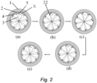
FIG. 2 is a cross-sectional schematic diagram of the working process of a strengthening device of a preferred embodiment of the present invention; -
FIG. 3 is a partially enlarged cross-sectional schematic diagram of the working process of a strengthening device of a preferred embodiment of the present invention; and -
FIG. 4 is a schematic diagram of the change of the arrangement of molecular chains of a tube of a preferred embodiment of the present invention from disordered to ordered,
wherein 1 - metal mold, 2 - polylactic acid tube, 3 - rotating blade, 31 - rotating shaft, 32 - first movable joint, 4 - distal blade, 41 - first end of the distal blade, 42 - second end of the distal blade, and 5 - control rod. - A plurality of preferred embodiments of the present invention are introduced below with reference to the description, in order to make the technical content thereof more clear and easier to understand. The present invention can be embodied in many different forms of embodiments, and the scope of protection of the present invention is not only limited to the embodiments mentioned herein.
- In the drawings, structurally the same components are indicated by the same reference signs, and structurally or functionally similar constituent parts throughout are indicated by similar reference signs. The size and thickness of each constituent part as shown in the drawings are arbitrarily shown, and the present invention does not limit the size and thickness of each constituent part. In order to make the illustration clearer, the thickness of parts is appropriately exaggerated somewhere in the drawings.
- As shown in
FIGS. 1 and2 , the device for radially strengthening a polylactic acid tube comprises ametal mold 1, arotating blade 3, adistal blade 4 and acontrol rod 5, wherein themetal mold 1 is tubular, and an inner wall thereof is used for accommodating apolylactic acid tube 2 to be strengthened. Therotating blade 3, thedistal blade 4 and thecontrol rod 5 are all arranged inside themetal mold 1. A rotatingshaft 31 of therotating blade 3 is arranged at an axial position of thetubular metal mold 1, and therotating blade 3 can rotate relative to the axial position of themetal mold 1. One end of therotating blade 3 is connected to therotating shaft 31, and the other end is movably connected to afirst end 41 of thedistal blade 4 so as to form a first movable joint 32; in addition, asecond end 42 of thedistal blade 4 opposite to thefirst end 41 is movably connected to thecontrol rod 5. Thecontrol rod 5 can control thedistal blade 4 to swing around the first movable joint 32 (i.e., taking the first movable joint 32 as a swing center), such that the included angle between thedistal blade 4 and themetal mold 1 changes, wherein the direction in which the included angle increases is a direction in which thedistal blade 4 opens. When the included angle between thedistal blade 4 and themetal mold 1 reaches the maximum, thedistal blade 4 is completely opened, wherein the value of the angle when the included angle between thedistal blade 4 and themetal mold 1 reaches the maximum is determined according to actual requirements, and the specific numerical value thereof does not constitute a limitation to the present application. The direction in which the included angle decreases is a direction in which thedistal blade 4 closes. Thecontrol rod 5 can control thedistal blade 4 to swing, so as to control the opening and closing of thedistal blade 4. -
FIGS. 2 and3 show the working process of the strengthening device, wherein (a) represents an initial state, (b) represents the opening process of thedistal blade 4, (c) represents the state when thedistal blade 4 is completely opened, (d) represents the closing process of thedistal blade 4, and (e) represents a state in which thedistal blade 4 is completely closed. - The
second end 42 of thedistal blade 4 may be set to have a rounded corner. - The
metal mold 1 may be made of a metal with a good thermal conductivity. Therotating blade 3 may be made of an antirust material, preferably an antirust metal. - The method for radially strengthening a polylactic acid tube using the above-mentioned device for radially strengthening a polylactic acid tube is described below by means of several embodiments.
- As shown in
FIGS. 1 ,2 and3 , apolylactic acid tube 2 to be strengthened was put into ametal mold 1, wherein the wall thickness of thepolylactic acid tube 2 was 50-100 um, themetal mold 1 was heated to a starting temperature T1 that exceeded the vitrification of the polylactic acid tube, and the temperature was maintained for 5 min; therotating blade 3 was then rotated along the rotatingshaft 31 in a rotation direction as indicated by an X direction inFIGS. 2 and3 , so as to drive thedistal blade 4 to rotate, wherein the X direction was a direction along the swing center of thedistal blade 4 and away from thesecond end 42 of thedistal blade 4, and the rotating speed of therotating blade 3 was controlled between 1 and 20 rpm, and at the same time, thedistal blade 4 was opened at a speed of 0.1°/min using thecontrol rod 5 and gradually approached themetal mold 1; and when the opening of thedistal blade 4 exceeded 2°, the opening of thedistal blade 4 was suspended, and the temperature was raised to an end temperature T2 of the vitrification of the polylactic acid tube. After the end temperature T2 was reached, the rotating speed of therotating blade 3 was controlled to 20-60 rpm, and thedistal blade 4 continued to be opened until thedistal blade 4 was completely opened; after squeezing and scraping for a period of time, thedistal blade 4 was closed at a speed of 0.1 °/min and restored to the initial state; and themetal mold 1 was cooled to room temperature, the strengthenedpolylactic acid tube 2 was took out, and redundant 2 mm tube sections at both ends of the processed tube were cut off. During the rotation process, thepolylactic acid tube 2 was squeezed and scraped by thedistal blade 4, and molecular chains thereof were oriented along the rotation direction of the blade, thereby achieving a change from a disordered arrangement to a circumferential orientation as shown inFIG. 4 . - As shown in
FIGS. 1 ,2 and3 , apolylactic acid tube 2 to be strengthened was put into ametal mold 1, wherein the wall thickness of thepolylactic acid tube 2 was 150-200 um, themetal mold 1 was heated to a starting temperature T1 that exceeded the vitrification of the polylactic acid tube, and the temperature was maintained for 20 min; therotating blade 3 was then rotated along the rotatingshaft 31 in a rotation direction as indicated by an X direction inFIGS. 2 and3 , so as to drive thedistal blade 4 to rotate, wherein the X direction was a direction along the swing center of thedistal blade 4 and away from thesecond end 42 of thedistal blade 4, and the rotating speed of therotating blade 3 was controlled between 1 and 20 rpm, and at the same time, thedistal blade 4 was opened at a speed of 0.1°/min using thecontrol rod 5 and gradually approached themetal mold 1; and when the opening of thedistal blade 4 exceeded 2°, the opening of thedistal blade 4 was suspended, and the temperature was raised to an end temperature T2 of the vitrification of the polylactic acid tube. After the end temperature T2 was reached, the rotating speed of therotating blade 3 was controlled to 20-60 rpm, and thedistal blade 4 continued to be opened until thedistal blade 4 was completely opened; after squeezing and scraping for a period of time, thedistal blade 4 was closed at a speed of 0.1°/min and restored to the initial state; and themetal mold 1 was cooled to room temperature, the strengthenedpolylactic acid tube 2 was took out, and redundant 2 mm tube sections at both ends of the processed tube were cut off. During the rotation process, thepolylactic acid tube 2 was squeezed and scraped by thedistal blade 4, and molecular chains thereof were oriented along the rotation direction of the blade, thereby achieving a change from a disordered arrangement to a circumferential orientation as shown inFIG. 4 . - As shown in
FIGS. 1 ,2 and3 , apolylactic acid tube 2 to be strengthened was put into ametal mold 1, wherein the wall thickness of thepolylactic acid tube 2 was 300-500 um, themetal mold 1 was heated to a starting temperature T1 that exceeded the vitrification of the polylactic acid tube, and the temperature was maintained for 30 min; therotating blade 3 was then rotated along the rotatingshaft 31 in a rotation direction as indicated by an X direction inFIGS. 2 and3 , so as to drive thedistal blade 4 to rotate, wherein the X direction was a direction along the swing center of thedistal blade 4 and away from thesecond end 42 of thedistal blade 4, and the rotating speed of therotating blade 3 was controlled between 1 and 20 rpm, and at the same time, thedistal blade 4 was opened at a speed of 0.1°/min using thecontrol rod 5 and gradually approached themetal mold 1; and when the opening of thedistal blade 4 exceeded 2°, the opening of thedistal blade 4 was suspended, and the temperature was raised to an end temperature T2 of the vitrification of the polylactic acid tube. After the end temperature T2 was reached, the rotating speed of therotating blade 3 was controlled to 20-60 rpm, and thedistal blade 4 continued to be opened until thedistal blade 4 was completely opened; after squeezing and scraping for a period of time, thedistal blade 4 was closed at a speed of 0.1°/min and restored to the initial state; and themetal mold 1 was cooled to room temperature, the strengthenedpolylactic acid tube 2 was took out, and redundant 2 mm tube sections at both ends of the processed tube were cut off. During the rotation process, thepolylactic acid tube 2 was squeezed and scraped by thedistal blade 4, and molecular chains thereof were oriented along the rotation direction of the blade, thereby achieving a change from a disordered arrangement to a circumferential orientation as shown inFIG. 4 .
Claims (15)
- A device for radially strengthening a polylactic acid tube (2), wherein the device comprises a tubular mold (1), said device being characterized by a rotating blade (3) and a distal blade (4); a rotating shaft (31) of the rotating blade (3) is arranged at an axial position of the tubular mold (1) and can rotate relative to the axial position; a first end (41) of the distal blade is movably connected to an end of the rotating blade (3) far away from the rotating shaft (31); and a second end (42) of the distal blade is connected to a control rod (5), opening and closing are achieved under the control of the control rod (5), and a joint between the distal blade (4) and the rotating blade (3) is a swing center.
- The device for radially strengthening a polylactic acid tube of claim 1, wherein the tubular mold (1) is a metal piece.
- The device for radially strengthening a polylactic acid tube of claim 1, wherein the second end (42) of the distal blade is a rounded corner.
- The device for radially strengthening a polylactic acid tube of claim 1, wherein the rotating blade (3) is made of an antirust material, preferably an antirust metal.
- The device for radially strengthening a polylactic acid tube of claim 1, wherein the wall thickness of the polylactic acid tube (2) is 50-500 um.
- A method for radially strengthening a polylactic acid tube using the device for radially strengthening a polylactic acid tube of claim 1, wherein the method comprises the following steps:1. loading the polylactic acid tube (2) to be strengthened into the strengthening device, heating the strengthening device to a first temperature, and maintaining the first temperature for a first preset time;2. rotating the rotating blade (3) of the strengthening device in a constant direction while opening the distal blade (4) of the strengthening device at a first speed, such that the second end (42) of the distal blade approaches the metal mold (1) of the strengthening device;3. when the opening of the distal blade (4) exceeds 2°, suspending the opening of the distal blade and heating the strengthening device to a second temperature T2; and
after the second temperature is reached, continuing to open the distal blade (4) until the distal blade is completely opened;4. after squeezing and scraping for a second preset time, closing the distal blade (4) at a second speed and restoring the distal blade (4) to an initial state;5. cooling the strengthening device to room temperature; and6. taking out the strengthened polylactic acid tube (2), and cutting off redundant tube sections at both ends of the polylactic acid tube. - The method for radially strengthening a polylactic acid tube of claim 6, wherein in step 1, the first temperature is a starting temperature T1 that is higher than the vitrification of the polylactic acid tube.
- The method for radially strengthening a polylactic acid tube of claim 6, wherein in step 3, the second temperature is an end temperature T2 of the vitrification of the polylactic acid tube.
- The method for radially strengthening a polylactic acid tube of claim 6, wherein in step 1, the first preset time is 5-30 min; preferably if the wall thickness of the polylactic acid tube is 50-500 um, the first preset time is 5 min; preferably if the wall thickness of the polylactic acid tube is 150-200 um, the first preset time is 20 min; preferably if the wall thickness of the polylactic acid tube (2) is 300-500 um, the first preset time is 30 min.
- The method for radially strengthening a polylactic acid tube of claim 6, wherein in step 2, the first speed is 0. 1°/min, and the rotating speed of the rotating blade is 1-20 rpm.
- The method for radially strengthening a polylactic acid tube of claim 6, wherein in step 4, the second speed is 0. 1°/min.
- The method for radially strengthening a polylactic acid tube of claim 6, wherein in step 3, the rotating speed of the rotating blade (3) is 20-60 rpm
- The method for radially strengthening a polylactic acid tube of claim 6, wherein in step 2, the constant direction is a direction in which the rotating blade (3) rotates along the rotating shaft (31) of the rotating blade to drive the distal blade (4) to rotate along the swing center of the distal blade while facing away from the second end (42) of the distal blade
- The method for radially strengthening a polylactic acid tube of claim 6, wherein in step 4, the second preset time refers to the time taken for molecular chains of the polylactic acid tube (2) to be oriented along the rotation direction of the rotating blade (3) from a disordered arrangement to a circumferential orientation.
- The method for radially strengthening a polylactic acid tube of claim 6, wherein in step 6, the length of the tube sections cut off at both ends of the polylactic acid tube (2) is 2 mm.
Applications Claiming Priority (2)
| Application Number | Priority Date | Filing Date | Title |
|---|---|---|---|
| CN202010672032.1A CN111559098B (en) | 2020-07-14 | 2020-07-14 | Circumferential strengthening device and method for polylactic acid pipe |
| PCT/CN2021/083756 WO2022012087A1 (en) | 2020-07-14 | 2021-03-30 | Radial strengthening device and method for polylactic acid tube |
Publications (3)
| Publication Number | Publication Date |
|---|---|
| EP4094930A1 EP4094930A1 (en) | 2022-11-30 |
| EP4094930A4 EP4094930A4 (en) | 2023-12-20 |
| EP4094930B1 true EP4094930B1 (en) | 2024-09-25 |
Family
ID=72068892
Family Applications (1)
| Application Number | Title | Priority Date | Filing Date |
|---|---|---|---|
| EP21842835.7A Active EP4094930B1 (en) | 2020-07-14 | 2021-03-30 | Radial strengthening device and method for polylactic acid tube |
Country Status (4)
| Country | Link |
|---|---|
| US (1) | US12233610B2 (en) |
| EP (1) | EP4094930B1 (en) |
| CN (1) | CN111559098B (en) |
| WO (1) | WO2022012087A1 (en) |
Families Citing this family (1)
| Publication number | Priority date | Publication date | Assignee | Title |
|---|---|---|---|---|
| CN111559098B (en) * | 2020-07-14 | 2020-11-20 | 上海百心安生物技术有限公司 | Circumferential strengthening device and method for polylactic acid pipe |
Family Cites Families (11)
| Publication number | Priority date | Publication date | Assignee | Title |
|---|---|---|---|---|
| CN1073922C (en) * | 1997-12-31 | 2001-10-31 | 四川联合大学 | Prepn. method and appts. for self-strengthening plastic pipe material |
| ATE298662T1 (en) | 2001-01-15 | 2005-07-15 | Michelin Soc Tech | SHAPING DRUM FOR TIRE PRODUCTION |
| US7906066B2 (en) * | 2006-06-30 | 2011-03-15 | Abbott Cardiovascular Systems, Inc. | Method of making a balloon catheter shaft having high strength and flexibility |
| CN102126297B (en) * | 2011-02-12 | 2013-06-05 | 天津大学 | Axial and radial stretching type tire molding drum |
| US20130226278A1 (en) | 2012-02-23 | 2013-08-29 | Tyco Healthcare Group Lp | Methods and apparatus for luminal stenting |
| CN108016023A (en) | 2012-12-21 | 2018-05-11 | 上海微创医疗器械(集团)有限公司 | A kind of preparation method of polylactide and its copolymer stent |
| GB201403767D0 (en) * | 2014-03-04 | 2014-04-16 | Rolls Royce Plc | Support structure for radial application |
| US10518003B2 (en) * | 2014-07-07 | 2019-12-31 | Meril Life Sciences Pvt. Ltd. | Method to manufacture thin strut stent from bioabsorbable polymer with high fatigue and radial strength |
| US10022906B2 (en) * | 2014-07-30 | 2018-07-17 | Abbott Cardiovascular Systems Inc. | Methods for solid phase processing of tubes and medical devices made from the processed tubes |
| CN109503916B (en) * | 2018-07-13 | 2021-07-02 | 四川大学 | High-strength hydrostatic pressure-resistant polyethylene pipe and preparation method thereof |
| CN111559098B (en) * | 2020-07-14 | 2020-11-20 | 上海百心安生物技术有限公司 | Circumferential strengthening device and method for polylactic acid pipe |
-
2020
- 2020-07-14 CN CN202010672032.1A patent/CN111559098B/en active Active
-
2021
- 2021-03-30 EP EP21842835.7A patent/EP4094930B1/en active Active
- 2021-03-30 WO PCT/CN2021/083756 patent/WO2022012087A1/en not_active Ceased
-
2023
- 2023-01-05 US US18/093,408 patent/US12233610B2/en active Active
Also Published As
| Publication number | Publication date |
|---|---|
| US20230150213A1 (en) | 2023-05-18 |
| EP4094930A4 (en) | 2023-12-20 |
| CN111559098B (en) | 2020-11-20 |
| EP4094930A1 (en) | 2022-11-30 |
| WO2022012087A1 (en) | 2022-01-20 |
| CN111559098A (en) | 2020-08-21 |
| US12233610B2 (en) | 2025-02-25 |
Similar Documents
| Publication | Publication Date | Title |
|---|---|---|
| US6739033B2 (en) | Thermal regulation of a coated work-piece during the reconfiguration of the coated work-piece | |
| US8904619B2 (en) | Methods for crimping a polymeric stent onto a delivery balloon | |
| DE69812466T2 (en) | Method of making a balloon | |
| JP4065319B2 (en) | Method for forming PTFE tube | |
| US10703050B2 (en) | Method of increasing stent retention of bioabsorbable scaffolding with a sheath | |
| US12233610B2 (en) | Device and method for radially strengthening polylactic acid tube | |
| EP3413845B1 (en) | Radial compression apparatus and method of incrementally compressing an article using same | |
| US9278477B2 (en) | Tube expansion processes for semicrystalline polymers to maximize fracture toughness | |
| US20050240256A1 (en) | Method and apparatus for contracting, loading or crimping self-expanding and balloon expandable stent devices | |
| JP6058641B2 (en) | Method and system for producing polymer endoprostheses by injection molding and blow molding | |
| EP3180046B1 (en) | Methods for solid phase processing of polymer tubes for medical devices | |
| JP2008307405A (en) | Method of manufacturing vascular stent yarn | |
| PT731748E (en) | METHOD FOR THE MANUFACTURE OF TUBULAR ARTICLES OF WALL AND ENDED CLOSURE FROM THERMOPLASTIC ELASTOMERS | |
| US10555825B2 (en) | Rotation of a medical device during crimping | |
| JPH10179753A (en) | Production of inclination angle of catheter | |
| WO2018107466A1 (en) | Biodegradable thrombus filter, and manufacturing method, application, and delivery device thereof | |
| US5340526A (en) | Temperature conditioning | |
| JP2016532498A (en) | Bioabsorbable scaffold for the treatment of bifurcation lesions | |
| US10207449B2 (en) | Sequential biaxial strain of semi-crystalline tubes | |
| EP0021438B1 (en) | Method of manufacturing shrinkable sleeves from cross-linking plastics material | |
| JP4446530B2 (en) | Method for correcting average diameter of ring material having metal coating layer | |
| CN117600407B (en) | Mould shell firing device for investment casting | |
| CN111793746A (en) | A valve stent heat treatment tool | |
| CN116115835A (en) | Bioabsorbable polymer stent and preparation method thereof | |
| CN120938687A (en) | A fully absorbable and degradable peripheral scaffold and its preparation method |
Legal Events
| Date | Code | Title | Description |
|---|---|---|---|
| STAA | Information on the status of an ep patent application or granted ep patent |
Free format text: STATUS: THE INTERNATIONAL PUBLICATION HAS BEEN MADE |
|
| PUAI | Public reference made under article 153(3) epc to a published international application that has entered the european phase |
Free format text: ORIGINAL CODE: 0009012 |
|
| STAA | Information on the status of an ep patent application or granted ep patent |
Free format text: STATUS: REQUEST FOR EXAMINATION WAS MADE |
|
| 17P | Request for examination filed |
Effective date: 20220826 |
|
| AK | Designated contracting states |
Kind code of ref document: A1 Designated state(s): AL AT BE BG CH CY CZ DE DK EE ES FI FR GB GR HR HU IE IS IT LI LT LU LV MC MK MT NL NO PL PT RO RS SE SI SK SM TR |
|
| DAV | Request for validation of the european patent (deleted) | ||
| DAX | Request for extension of the european patent (deleted) | ||
| A4 | Supplementary search report drawn up and despatched |
Effective date: 20231121 |
|
| RIC1 | Information provided on ipc code assigned before grant |
Ipc: B29L 23/00 20060101ALN20231115BHEP Ipc: B29K 67/00 20060101ALN20231115BHEP Ipc: A61L 31/14 20060101ALI20231115BHEP Ipc: A61L 31/06 20060101ALI20231115BHEP Ipc: A61F 2/82 20130101ALI20231115BHEP Ipc: A61F 2/04 20130101ALI20231115BHEP Ipc: B29C 71/00 20060101ALI20231115BHEP Ipc: B29C 71/02 20060101AFI20231115BHEP |
|
| RIC1 | Information provided on ipc code assigned before grant |
Ipc: B29L 23/00 20060101ALN20240507BHEP Ipc: B29K 67/00 20060101ALN20240507BHEP Ipc: A61L 31/14 20060101ALI20240507BHEP Ipc: A61L 31/06 20060101ALI20240507BHEP Ipc: A61F 2/82 20130101ALI20240507BHEP Ipc: A61F 2/04 20130101ALI20240507BHEP Ipc: B29C 71/00 20060101ALI20240507BHEP Ipc: B29C 71/02 20060101AFI20240507BHEP |
|
| GRAP | Despatch of communication of intention to grant a patent |
Free format text: ORIGINAL CODE: EPIDOSNIGR1 |
|
| STAA | Information on the status of an ep patent application or granted ep patent |
Free format text: STATUS: GRANT OF PATENT IS INTENDED |
|
| INTG | Intention to grant announced |
Effective date: 20240705 |
|
| RIC1 | Information provided on ipc code assigned before grant |
Ipc: B29L 23/00 20060101ALN20240624BHEP Ipc: B29K 67/00 20060101ALN20240624BHEP Ipc: A61L 31/14 20060101ALI20240624BHEP Ipc: A61L 31/06 20060101ALI20240624BHEP Ipc: A61F 2/82 20130101ALI20240624BHEP Ipc: A61F 2/04 20130101ALI20240624BHEP Ipc: B29C 71/00 20060101ALI20240624BHEP Ipc: B29C 71/02 20060101AFI20240624BHEP |
|
| GRAS | Grant fee paid |
Free format text: ORIGINAL CODE: EPIDOSNIGR3 |
|
| GRAA | (expected) grant |
Free format text: ORIGINAL CODE: 0009210 |
|
| STAA | Information on the status of an ep patent application or granted ep patent |
Free format text: STATUS: THE PATENT HAS BEEN GRANTED |
|
| AK | Designated contracting states |
Kind code of ref document: B1 Designated state(s): AL AT BE BG CH CY CZ DE DK EE ES FI FR GB GR HR HU IE IS IT LI LT LU LV MC MK MT NL NO PL PT RO RS SE SI SK SM TR |
|
| REG | Reference to a national code |
Ref country code: GB Ref legal event code: FG4D |
|
| REG | Reference to a national code |
Ref country code: CH Ref legal event code: EP |
|
| REG | Reference to a national code |
Ref country code: DE Ref legal event code: R096 Ref document number: 602021019436 Country of ref document: DE |
|
| REG | Reference to a national code |
Ref country code: IE Ref legal event code: FG4D |
|
| REG | Reference to a national code |
Ref country code: LT Ref legal event code: MG9D |
|
| PG25 | Lapsed in a contracting state [announced via postgrant information from national office to epo] |
Ref country code: NO Free format text: LAPSE BECAUSE OF FAILURE TO SUBMIT A TRANSLATION OF THE DESCRIPTION OR TO PAY THE FEE WITHIN THE PRESCRIBED TIME-LIMIT Effective date: 20241225 |
|
| PG25 | Lapsed in a contracting state [announced via postgrant information from national office to epo] |
Ref country code: GR Free format text: LAPSE BECAUSE OF FAILURE TO SUBMIT A TRANSLATION OF THE DESCRIPTION OR TO PAY THE FEE WITHIN THE PRESCRIBED TIME-LIMIT Effective date: 20241226 Ref country code: FI Free format text: LAPSE BECAUSE OF FAILURE TO SUBMIT A TRANSLATION OF THE DESCRIPTION OR TO PAY THE FEE WITHIN THE PRESCRIBED TIME-LIMIT Effective date: 20240925 |
|
| PG25 | Lapsed in a contracting state [announced via postgrant information from national office to epo] |
Ref country code: BG Free format text: LAPSE BECAUSE OF FAILURE TO SUBMIT A TRANSLATION OF THE DESCRIPTION OR TO PAY THE FEE WITHIN THE PRESCRIBED TIME-LIMIT Effective date: 20240925 |
|
| PG25 | Lapsed in a contracting state [announced via postgrant information from national office to epo] |
Ref country code: LV Free format text: LAPSE BECAUSE OF FAILURE TO SUBMIT A TRANSLATION OF THE DESCRIPTION OR TO PAY THE FEE WITHIN THE PRESCRIBED TIME-LIMIT Effective date: 20240925 |
|
| PG25 | Lapsed in a contracting state [announced via postgrant information from national office to epo] |
Ref country code: RS Free format text: LAPSE BECAUSE OF FAILURE TO SUBMIT A TRANSLATION OF THE DESCRIPTION OR TO PAY THE FEE WITHIN THE PRESCRIBED TIME-LIMIT Effective date: 20241225 |
|
| REG | Reference to a national code |
Ref country code: NL Ref legal event code: MP Effective date: 20240925 |
|
| PG25 | Lapsed in a contracting state [announced via postgrant information from national office to epo] |
Ref country code: RS Free format text: LAPSE BECAUSE OF FAILURE TO SUBMIT A TRANSLATION OF THE DESCRIPTION OR TO PAY THE FEE WITHIN THE PRESCRIBED TIME-LIMIT Effective date: 20241225 Ref country code: NO Free format text: LAPSE BECAUSE OF FAILURE TO SUBMIT A TRANSLATION OF THE DESCRIPTION OR TO PAY THE FEE WITHIN THE PRESCRIBED TIME-LIMIT Effective date: 20241225 Ref country code: LV Free format text: LAPSE BECAUSE OF FAILURE TO SUBMIT A TRANSLATION OF THE DESCRIPTION OR TO PAY THE FEE WITHIN THE PRESCRIBED TIME-LIMIT Effective date: 20240925 Ref country code: GR Free format text: LAPSE BECAUSE OF FAILURE TO SUBMIT A TRANSLATION OF THE DESCRIPTION OR TO PAY THE FEE WITHIN THE PRESCRIBED TIME-LIMIT Effective date: 20241226 Ref country code: FI Free format text: LAPSE BECAUSE OF FAILURE TO SUBMIT A TRANSLATION OF THE DESCRIPTION OR TO PAY THE FEE WITHIN THE PRESCRIBED TIME-LIMIT Effective date: 20240925 Ref country code: BG Free format text: LAPSE BECAUSE OF FAILURE TO SUBMIT A TRANSLATION OF THE DESCRIPTION OR TO PAY THE FEE WITHIN THE PRESCRIBED TIME-LIMIT Effective date: 20240925 |
|
| REG | Reference to a national code |
Ref country code: AT Ref legal event code: MK05 Ref document number: 1726327 Country of ref document: AT Kind code of ref document: T Effective date: 20240925 |
|
| PG25 | Lapsed in a contracting state [announced via postgrant information from national office to epo] |
Ref country code: NL Free format text: LAPSE BECAUSE OF FAILURE TO SUBMIT A TRANSLATION OF THE DESCRIPTION OR TO PAY THE FEE WITHIN THE PRESCRIBED TIME-LIMIT Effective date: 20240925 |
|
| PG25 | Lapsed in a contracting state [announced via postgrant information from national office to epo] |
Ref country code: PT Free format text: LAPSE BECAUSE OF FAILURE TO SUBMIT A TRANSLATION OF THE DESCRIPTION OR TO PAY THE FEE WITHIN THE PRESCRIBED TIME-LIMIT Effective date: 20250127 Ref country code: IS Free format text: LAPSE BECAUSE OF FAILURE TO SUBMIT A TRANSLATION OF THE DESCRIPTION OR TO PAY THE FEE WITHIN THE PRESCRIBED TIME-LIMIT Effective date: 20250125 |
|
| PG25 | Lapsed in a contracting state [announced via postgrant information from national office to epo] |
Ref country code: RO Free format text: LAPSE BECAUSE OF FAILURE TO SUBMIT A TRANSLATION OF THE DESCRIPTION OR TO PAY THE FEE WITHIN THE PRESCRIBED TIME-LIMIT Effective date: 20240925 Ref country code: SM Free format text: LAPSE BECAUSE OF FAILURE TO SUBMIT A TRANSLATION OF THE DESCRIPTION OR TO PAY THE FEE WITHIN THE PRESCRIBED TIME-LIMIT Effective date: 20240925 |
|
| PG25 | Lapsed in a contracting state [announced via postgrant information from national office to epo] |
Ref country code: ES Free format text: LAPSE BECAUSE OF FAILURE TO SUBMIT A TRANSLATION OF THE DESCRIPTION OR TO PAY THE FEE WITHIN THE PRESCRIBED TIME-LIMIT Effective date: 20240925 |
|
| PG25 | Lapsed in a contracting state [announced via postgrant information from national office to epo] |
Ref country code: EE Free format text: LAPSE BECAUSE OF FAILURE TO SUBMIT A TRANSLATION OF THE DESCRIPTION OR TO PAY THE FEE WITHIN THE PRESCRIBED TIME-LIMIT Effective date: 20240925 Ref country code: AT Free format text: LAPSE BECAUSE OF FAILURE TO SUBMIT A TRANSLATION OF THE DESCRIPTION OR TO PAY THE FEE WITHIN THE PRESCRIBED TIME-LIMIT Effective date: 20240925 |
|
| PG25 | Lapsed in a contracting state [announced via postgrant information from national office to epo] |
Ref country code: PL Free format text: LAPSE BECAUSE OF FAILURE TO SUBMIT A TRANSLATION OF THE DESCRIPTION OR TO PAY THE FEE WITHIN THE PRESCRIBED TIME-LIMIT Effective date: 20240925 Ref country code: CZ Free format text: LAPSE BECAUSE OF FAILURE TO SUBMIT A TRANSLATION OF THE DESCRIPTION OR TO PAY THE FEE WITHIN THE PRESCRIBED TIME-LIMIT Effective date: 20240925 |
|
| PG25 | Lapsed in a contracting state [announced via postgrant information from national office to epo] |
Ref country code: SK Free format text: LAPSE BECAUSE OF FAILURE TO SUBMIT A TRANSLATION OF THE DESCRIPTION OR TO PAY THE FEE WITHIN THE PRESCRIBED TIME-LIMIT Effective date: 20240925 Ref country code: IT Free format text: LAPSE BECAUSE OF FAILURE TO SUBMIT A TRANSLATION OF THE DESCRIPTION OR TO PAY THE FEE WITHIN THE PRESCRIBED TIME-LIMIT Effective date: 20240925 |
|
| REG | Reference to a national code |
Ref country code: DE Ref legal event code: R097 Ref document number: 602021019436 Country of ref document: DE |
|
| PG25 | Lapsed in a contracting state [announced via postgrant information from national office to epo] |
Ref country code: DK Free format text: LAPSE BECAUSE OF FAILURE TO SUBMIT A TRANSLATION OF THE DESCRIPTION OR TO PAY THE FEE WITHIN THE PRESCRIBED TIME-LIMIT Effective date: 20240925 |
|
| PLBE | No opposition filed within time limit |
Free format text: ORIGINAL CODE: 0009261 |
|
| STAA | Information on the status of an ep patent application or granted ep patent |
Free format text: STATUS: NO OPPOSITION FILED WITHIN TIME LIMIT |
|
| 26N | No opposition filed |
Effective date: 20250626 |
|
| PG25 | Lapsed in a contracting state [announced via postgrant information from national office to epo] |
Ref country code: SE Free format text: LAPSE BECAUSE OF FAILURE TO SUBMIT A TRANSLATION OF THE DESCRIPTION OR TO PAY THE FEE WITHIN THE PRESCRIBED TIME-LIMIT Effective date: 20240925 |
|
| REG | Reference to a national code |
Ref country code: DE Ref legal event code: R119 Ref document number: 602021019436 Country of ref document: DE |
|
| PG25 | Lapsed in a contracting state [announced via postgrant information from national office to epo] |
Ref country code: MC Free format text: LAPSE BECAUSE OF FAILURE TO SUBMIT A TRANSLATION OF THE DESCRIPTION OR TO PAY THE FEE WITHIN THE PRESCRIBED TIME-LIMIT Effective date: 20240925 |
|
| REG | Reference to a national code |
Ref country code: CH Ref legal event code: H13 Free format text: ST27 STATUS EVENT CODE: U-0-0-H10-H13 (AS PROVIDED BY THE NATIONAL OFFICE) Effective date: 20251023 |
|
| PG25 | Lapsed in a contracting state [announced via postgrant information from national office to epo] |
Ref country code: LU Free format text: LAPSE BECAUSE OF NON-PAYMENT OF DUE FEES Effective date: 20250330 |
|
| GBPC | Gb: european patent ceased through non-payment of renewal fee |
Effective date: 20250330 |
|
| REG | Reference to a national code |
Ref country code: BE Ref legal event code: MM Effective date: 20250331 |
|
| PG25 | Lapsed in a contracting state [announced via postgrant information from national office to epo] |
Ref country code: DE Free format text: LAPSE BECAUSE OF NON-PAYMENT OF DUE FEES Effective date: 20251001 |
|
| PG25 | Lapsed in a contracting state [announced via postgrant information from national office to epo] |
Ref country code: GB Free format text: LAPSE BECAUSE OF NON-PAYMENT OF DUE FEES Effective date: 20250330 |
|
| PG25 | Lapsed in a contracting state [announced via postgrant information from national office to epo] |
Ref country code: HR Free format text: LAPSE BECAUSE OF FAILURE TO SUBMIT A TRANSLATION OF THE DESCRIPTION OR TO PAY THE FEE WITHIN THE PRESCRIBED TIME-LIMIT Effective date: 20240925 |
|
| PG25 | Lapsed in a contracting state [announced via postgrant information from national office to epo] |
Ref country code: BE Free format text: LAPSE BECAUSE OF NON-PAYMENT OF DUE FEES Effective date: 20250331 |
|
| PG25 | Lapsed in a contracting state [announced via postgrant information from national office to epo] |
Ref country code: CH Free format text: LAPSE BECAUSE OF NON-PAYMENT OF DUE FEES Effective date: 20250331 |
|
| PG25 | Lapsed in a contracting state [announced via postgrant information from national office to epo] |
Ref country code: IE Free format text: LAPSE BECAUSE OF NON-PAYMENT OF DUE FEES Effective date: 20250330 |
|
| PGFP | Annual fee paid to national office [announced via postgrant information from national office to epo] |
Ref country code: FR Payment date: 20260330 Year of fee payment: 6 |