EP4094874A1 - Welding device - Google Patents
Welding device Download PDFInfo
- Publication number
- EP4094874A1 EP4094874A1 EP21743742.5A EP21743742A EP4094874A1 EP 4094874 A1 EP4094874 A1 EP 4094874A1 EP 21743742 A EP21743742 A EP 21743742A EP 4094874 A1 EP4094874 A1 EP 4094874A1
- Authority
- EP
- European Patent Office
- Prior art keywords
- time
- welding
- predetermined
- current
- start operation
- Prior art date
- Legal status (The legal status is an assumption and is not a legal conclusion. Google has not performed a legal analysis and makes no representation as to the accuracy of the status listed.)
- Granted
Links
Images


Classifications
-
- B—PERFORMING OPERATIONS; TRANSPORTING
- B23—MACHINE TOOLS; METAL-WORKING NOT OTHERWISE PROVIDED FOR
- B23K—SOLDERING OR UNSOLDERING; WELDING; CLADDING OR PLATING BY SOLDERING OR WELDING; CUTTING BY APPLYING HEAT LOCALLY, e.g. FLAME CUTTING; WORKING BY LASER BEAM
- B23K9/00—Arc welding or cutting
- B23K9/06—Arrangements or circuits for starting the arc, e.g. by generating ignition voltage, or for stabilising the arc
- B23K9/067—Starting the arc
- B23K9/0672—Starting the arc without direct contact between electrodes
-
- B—PERFORMING OPERATIONS; TRANSPORTING
- B23—MACHINE TOOLS; METAL-WORKING NOT OTHERWISE PROVIDED FOR
- B23K—SOLDERING OR UNSOLDERING; WELDING; CLADDING OR PLATING BY SOLDERING OR WELDING; CUTTING BY APPLYING HEAT LOCALLY, e.g. FLAME CUTTING; WORKING BY LASER BEAM
- B23K9/00—Arc welding or cutting
- B23K9/16—Arc welding or cutting making use of shielding gas
- B23K9/167—Arc welding or cutting making use of shielding gas and of a non-consumable electrode
Definitions
- the present disclosure relates to a welding device that performs welding by generating an arc between a tungsten electrode and a welding target.
- a welding device that is disclosed in PTL 1 includes: a high frequency voltage application unit that applies a high frequency voltage between a tungsten electrode and a welding target; a current detection unit that detects a welding current; and a controller that acquires, at a time of performing a start operation for starting applying of the high frequency voltage to the high frequency voltage application unit, a delay time from starting of the start operation to the detection of the welding current by the current detection unit, and performs a processing at an abnormal time such as allowing a warning device to output warning when the delay time is more than or equal to a predetermined time.
- the controller performs the processing at an abnormal time. Accordingly, the processing at an abnormal time is likely to be performed due to a temporary factor other than wear of a tungsten electrode or the formation of smear on the tungsten electrode.
- the present disclosure has been made in view of the above-mentioned circumstance, and it is an object of the present disclosure to provide a welding device that can suppress the performing of the processing at an abnormal time due to a temporary factor other than wear of a tungsten electrode or the formation of smear on the tungsten electrode.
- a welding device configured to perform welding by generating an arc between a tungsten electrode and a welding target
- the welding device including: a high frequency voltage application unit configured to apply a high frequency voltage between the tungsten electrode and the welding target; a welding output circuit unit configured to control a welding current; a current detection unit configured to detect the welding current that is more than or equal to a predetermined current threshold; and a controller configured, at a time of performing a start operation for making the high frequency voltage application unit start applying of the high frequency voltage, to acquire a delay time from a point of time that the start operation is performed to a point of time that the welding current is detected by the current detection unit, to determine whether or not delay times corresponding to the delay time that are acquired at a plurality of previous points of time at which the start operation is performed satisfy a predetermined time condition, and to perform predetermined processing at an abnormal time in a case where the delay times satisfy the predetermined time condition.
- the controller determines whether or not the processing at an abnormal time is performed based on the delay times at the plurality of previous points of time at which the start operation is performed. Accordingly, compared with the case where whether or not the processing at an abnormal time is performed is determined based on the delay time at the time of performing the start operation one time as described in PTL 1, the processing at an abnormal time is minimally performed due to a temporary factor other than the wear of the tungsten electrode and the formation of smear on the tungsten electrode.
- the welding device can suppress the performing of the processing at an abnormal time due to a temporary factor other than wear of a tungsten electrode or the formation of smear on the tungsten electrode.
- Fig. 1 illustrates welding device 10 according to the exemplary embodiment of the present disclosure.
- Welding device 10 performs tungsten inert gas (TIG) welding by generating arc A between tungsten electrode 21 mounted on welding torch 20 and base material 30 that forms a welding target.
- welding device 10 includes input circuit unit 11, gas control device 12, high frequency voltage application unit 13, welding output circuit unit 14, current detection unit 15, display data storage unit 16, display unit 17 that forms an output unit, controller 18, and delay time storage unit 19.
- Input circuit unit 11 outputs welding instruction signal S1 indicating an ON/OFF state of switch 22 mounted on welding torch 20.
- gas control device 12 When controller 18 starts outputting gas supply signal S2 to gas control device 12, gas control device 12 makes welding torch 20 start jetting of a shielding gas to base material 30.
- a shielding gas for example, an argon gas or the like is used.
- Gas control device 12 is connected to welding torch 20 by way of gas hose 23.
- controller 18 When controller 18 outputs high frequency voltage application signal S3 to high frequency voltage application unit 13, high frequency voltage application unit 13 applies a high frequency high voltage between tungsten electrode 21 and base material 30.
- Welding output circuit unit 14 controls a welding voltage and a welding current based on welding control signal S4 output from controller 18. Welding output circuit unit 14 is electrically connected to welding torch 20 via welding output cable 24.
- Current detection unit 15 detects a welding current more than or equal to a predetermined current threshold. As a specific operation, current detection unit 15 outputs current detection signal S5 when a welding current exceeds the current threshold.
- Display data storage unit 16 stores image data of an image to be output and displayed on display unit 17.
- the image data to be stored includes image data of first to fourth warning images as an output.
- the first warning image displays a message that "The electrode is getting smeared.”
- the second warning image displays a message that "The electrode is worn so that there is a possibility that the generation of an arc does not start.”
- the third warning image displays a message that "The electrode is largely worn and smeared. Polishing of the electrode is recommended”.
- the fourth warning image displays a message that "Please polish or exchange the electrode.”.
- Display unit 17 is, for example, a display. Display unit 17 outputs and displays an image based on image data stored in display data storage unit 16.
- Controller 18 selectively performs a control between a control in an AC output mode where welding control signal S4 is outputted to welding output circuit unit 14 in such a manner that a welding voltage and a welding current become an alternating current voltage and an alternating current respectively, and a control in a DC output mode where welding control signal S4 is output to welding output circuit unit 14 in such a manner that a welding voltage and a welding current become a direct current voltage and a direct current respectively.
- Controller 18 starts outputting of gas supply signal S2 when switch 22 of welding torch 20 is switched from an OFF state to an ON state so that welding instruction signal S1 output from input circuit unit 11 is switched from a signal indicating an OFF state to a signal indicating an ON state.
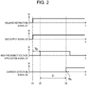
- controller 18 when predetermined preflow time Tp has elapsed from a point of time that outputting of gas supply signal S2 is started, controller 18 outputs high frequency voltage application signal S3 at timing t2 so as to perform a start operation where high frequency voltage application unit 13 is made to start application of a high frequency high voltage. Then, at this point of time that the voltage applying operation is started, controller 18 acquires delay time Tl (see Fig. 2 ) from a point of time that the start operation is started to a point of time that the detection of a welding current more than or equal to the current threshold by current detection unit 15 is started, and stores delay time Tl in delay time storage unit 19.
- controller 18 references delay times Tl at a plurality of points of time at which the start operation is performed including a current point of time at which the start operation is performed that are stored in delay time storage unit 19, and determines whether or not delay times Tl at the plurality of points of time at each of which the start operation is performed satisfy a predetermined time condition. Then, controller 18 performs processing at an abnormal time in a case where delay times Tl satisfy the predetermined time condition.
- the time condition is that the first number N1 (being 2 or more) of times of delay times Tl each of which exceeds a predetermined time threshold are included in delay times Tl at a plurality of recent number of points of time at which the start operation is performed.
- the time condition is stored in controller 18.
- Controller 18 changes the time condition by changing the time threshold in accordance with predetermined setting conditions.
- the setting conditions are an instruction value of a welding current, a flow rate of a shielding gas, a tip angle of tungsten electrode 21, the dopant concentration in tungsten electrode 21, a diameter of tungsten electrode 21, and a mode that is either an AC output mode or a DC output mode.
- the processing at an abnormal time is processing where controller 18 makes display unit 17 output and display any one of first to fourth warning images based on image data stored in display data storage unit 16. Specifically, in a case where the number LN of delay times Tl each of which exceeds the predetermined time threshold is more than or equal to the first number N1 and less than a predetermined second number N2 among delay times Tl at a plurality of recently-set number of points of time that the start operation is performed, the processing to be performed at an abnormal time becomes a process where controller 18 makes display unit 17 output and display the first warning image.
- the second number N2 is a value larger than the first number N1.
- the processing at an abnormal time becomes a process where controller 18 makes display unit 17 output and display the second warning image.
- the third number N3 is a value larger than the second number N2.
- the processing at an abnormal time becomes a process where controller 18 makes display unit 17 output and display the third warning image.
- the fourth number N4 is a value larger than the third number N3.
- the processing at an abnormal time becomes a process where controller 18 makes display unit 17 output and display the fourth warning image.
- the time thresholds and the first to fourth numbers N1 to N4 are set to appropriate values by experiments in advance.
- the above-mentioned set number of points of time that the start operation is performed is set to 100, and the numbers of the first to fourth numbers N1 to N4 are set to 10, 20, 30 and 40 in this order.
- the set number of points of time that the start operation is performed is larger than the first to fourth numbers N1 to N4
- the set number of points of time may be set to the number other than 100.
- the numbers of first to fourth numbers N1 to N4 may also be set to other numbers provided that a relationship described in the following expression 1 is established.
- controller 18 controls welding output circuit unit 14 based on welding control signal S4 in such a manner that, from a point of time that a welding current that is more than or equal to the current threshold is detected by current detection unit 15 to a point of time that predetermined hot start period Th (see Fig. 2 ) has elapsed, the welding current assumes a predetermined hot start set current value.
- controller 18 The functions of controller 18 are implemented by a central processing unit (CPU) and a storage device.
- CPU central processing unit
- Delay time storage unit 19 stores delay time Tl from a point of time that the start operation is started to a point of time that the detection of a welding current that is more than or equal to the above-described current threshold is performed by current detection unit 15.
- input circuit unit 11 When an operator turns on switch 22 of welding torch 20 at timing t1, input circuit unit 11 outputs welding instruction signal S1 that indicates that input circuit unit 11 is in an ON state.
- controller 18 starts outputting of gas supply signal S2, and gas control device 12 makes welding torch 20 start jetting of a shield gas to base material 30.
- controller 18 outputs high frequency voltage application signal S3 at timing t2 so as to perform a start operation where high frequency voltage application unit 13 is made to start application of the high frequency high voltage.
- controller 18 acquires delay time Tl from a point of time that the start operation is started to a point of time that current detection unit 15 detects a welding current more than or equal to the current threshold, and stores acquired delay time Tl.
- controller 18 controls welding output circuit unit 14 in such a manner that, from a point of time that a welding current that is more than or equal to the current threshold is detected by current detection unit 15 to a point of time that predetermined hot start period Th has elapsed, the welding current assumes a predetermined hot start set current value.
- Fig. 3 is a flowchart for describing detailed processing performed by controller 18 when switch 22 is switched from an OFF state to an ON state.
- controller 18 When switch 22 is switched from an OFF state to an ON state so that welding instruction signal S1 output from input circuit unit 11 is switched from a signal indicating an OFF state to a signal indicating an ON state, controller 18 starts outputting of gas supply signal S2 in S101.
- controller 18 waits for a lapse of predetermined preflow time Tp from a point of time that outputting of gas supply signal S2 is started in S101. Then, when predetermined preflow time Tp has elapsed from a point of time that the outputting of gas supply signal S2 is started in S101, in S103, controller 18 performs a start operation by outputting high frequency voltage application signal S3 so as to make high frequency voltage application unit 13 start application of a high frequency high voltage.
- controller 18 acquires delay time Tl from a point of time that the start operation is started in S103 to a point of time that a welding current more than or equal to the current threshold is detected by current detection unit 15, and controller 18 stores delay time Tl in delay time storage unit 19.
- controller 18 refers to delay times Tl at recent 100 points of time at which the start operation is performed that are stored in delay time storage unit 19, and determines whether or not the time condition that the first number N1, that is, 10 or more delay times Tl each of which exceeds the predetermined time threshold are included in the recent 100 points of time at which the start operation is performed. In a case where the first number N1 or more of delay times Tl that exceeds the predetermined time threshold are not included so that the time condition is not satisfied, the processing advances to S106. On the other hand, in a case where the first number N1 or more of delay times Tl that exceeds the predetermined time threshold are included so that the time condition is satisfied, the processing advances to S107.
- controller 18 does not perform the processing at an abnormal time.
- controller 18 refers to delay times Tl at recent 100 points of time at which the start operation is performed that are stored in delay time storage unit 19, and determines whether or not the number LN of delay times Tl that exceeds the predetermined time threshold is the second number N2, that is, less than 20 among delay times Tl at the recent 100 points of time at which the start operation is performed.
- the processing advances to S108.
- the processing advances to S109.
- controller 18 performs processing of outputting and displaying a first warning image that displays a message that "The electrode is getting smeared.” on display unit 17 as the processing at an abnormal time.
- controller 18 refers to delay times Tl at recent 100 points of time at which the start operation is performed that are stored in delay time storage unit 19, and determines whether or not the number LN of delay times Tl that exceeds the predetermined times threshold is the third number N3, that is, less than 30 among delay times Tl at the recent 100 points of time at which the start operation is performed.
- the processing advances to S110.
- the number LN of delay times Tl exceeding the predetermined time threshold is more than or equal to the third number N3, the processing advances to S111.
- controller 18 performs processing of outputting and displaying a second warning image that "The electrode is worn so that there is a possibility that the generation of an arc does not start.” on the display unit 17 as the processing at an abnormal time.
- controller 18 refers to delay times Tl at recent 100 points of time at which the start operation is performed that are stored in delay time storage unit 19, and determines whether or not the number LN of delay times Tl that exceeds the predetermined time threshold is the fourth number N4, that is, less than 40 among delay times Tl at the recent 100 points of time at which the start operation is performed.
- the processing advances to S112.
- the number LN of delay times Tl exceeding the predetermined time threshold is more than or equal to the fourth number N4, the processing advances to S113.
- controller 18 performs processing of making the display unit 17 output and display a third warning image "Wear of the electrode is large and smear on the electrode is large. Polishing of the electrode is recommended.” as the processing at an abnormal time.
- controller 18 performs processing of making display unit 17 output and display the fourth warning image that "Please polish or exchange the electrode.” as the processing at an abnormal time.
- controller 18 performs the processing at an abnormal time, and display unit 17 displays the first to fourth warning images. Accordingly, an operator can recognize the consumption or a smear on tungsten electrode 21, and can take a measure such as polishing tungsten electrode 21 or exchanging tungsten electrode 21. Therefore, it is possible to suppress the occurrence of a state where starting of an arc takes an excessively long time or starting of an arc cannot be performed due to consumption or smear on tungsten electrode 21.
- the controller determines whether or not the processing at an abnormal time should be performed based on the delay times Tl at a plurality of points of time at which the start operation is performed. Accordingly, compared with the case where the controller determines whether or not the processing at an abnormal time should be performed based on the delay time at a point of time at which the start operation is performed one time as described in PTL 1, the processing at an abnormal time is minimally performed due to a temporary factor other than the consumption and the smear on tungsten electrode 21. Therefore, unnecessary polishing or exchange of tungsten electrode 21 can be suppressed.
- the time condition is that delay time Tl in the current start operation exceeds predetermined threshold TH (see Fig. 4 ), and the number of times of the start operation performed between the current start operation and the previous start operation in which the delay time Tl exceeds the threshold TH is less than a predetermined reference number of times.
- the reference number of times is set to 20 times. However, the reference number of times may be set to another number of times.
- the processing at an abnormal time is always processing in which the first warning image is output to and displayed on display unit 17.
- the number of times NU1 of the start operations performed between the current start operation and the previous start operation in which the delay time Tl exceeds the threshold TH that is, the S1-th start operation is 20 times or more, that is, 85 times, and the time condition is not satisfied. Therefore, controller 18 does not make the display unit 17 output and display the first warning image.
- controller 18 makes display unit 17 output and display the first warning image.
- the processing at an abnormal time is always processing in which the first warning image is output and displayed on display unit 17.
- the time condition satisfies at least one among a first condition that the delay time Tl in the current start operation exceeds the predetermined first time threshold, a second condition that the number of delay times Tl that exceed the predetermined second time threshold is included in delay times Tl at a plurality of recently-set points of time including the present time at which the start operation is performed, and the number of such delay times Tl is more than or equal to a predetermined reference number, and a third condition that delay time Tl at the current start operation exceeds the predetermined third time threshold and the number of the start operations performed between the current start operation and the previous start operation in which delay time Tl exceeds a third time threshold becomes less than a predetermined reference number of times.
- the first to third time thresholds are set so as to satisfy the following expression 2.
- the processing at an abnormal time always is processing where controller 18 makes display unit 17 output and display the first warning image.
- the time condition is that the variance of delay times Tl that are acquired at a plurality of recently-set number of points of time at which the start operation is performed becomes more than or equal to a predetermined value.
- the set number of times is, for example, 100 times.
- the processing at an abnormal time may be processing where any one of the first to fourth warning images is selected, and is output and displayed corresponding to a value of the variance.
- controller 18 performs processing where a hot start set current value is changed to a larger current value as a processing at an abnormal time in place of the processing where any one of the first to fourth warning images is output to and is displayed on display unit 17.
- tungsten electrode 21 can be warmed faster.
- the hot start set current value is increased to such an extent that tungsten electrode 21 is not excessively consumed.
- the time condition is not limited to the conditions described in the above-described exemplary embodiment and the first to fourth modifications of the exemplary embodiment. Other appropriate conditions may be set by experiments.
- the time condition is set in such a manner that when delay times at a plurality of previous points of time at which the start operation is performed before the current time are input to a predetermined function, an output value of the function satisfies a predetermined numerical value condition.
- the time condition may be set in such a manner that when delay times at a plurality of previous points of time of start operation before the current time are input to artificial intelligence (AI), an output of the AI satisfies a predetermined condition.
- AI artificial intelligence
- the processing at an abnormal time is set to the processing where a hot start set current value is increased.
- the processing at an abnormal time may be set to processing where an after-flow time during which a shielding gas is continuously released after finishing of welding is prolonged.
- the processing at an abnormal time may be set to processing where other parameters such as a frequency of an output during an operation in an AC output mode are changed.
- controller 18 may perform both the processing where a hot start set current value is increased and the processing where controller 18 makes display unit 17 output and display the warning image.
- processing at an abnormal time is not limited to the processing where controller 18 makes display unit 17 output an image, and may make a voice output device output a voice.
- controller 18 changes the time condition in accordance with six setting conditions consisting of: an instruction value of a welding current, a flow rate of a shielding gas, a tip end angle of tungsten electrode 21, the dopant concentration in tungsten electrode 21, a diameter of tungsten electrode 21, and whether the mode is an alternating current (AC) output mode or a direct current (DC) output mode.
- the time condition may be changed in accordance with only a part of at least one of the six setting conditions. The time condition may not be changed.
- the welding device of the present disclosure can suppress the performing of processing at an abnormal time due to a temporary factor other than wear of the tungsten electrode and the formation of smear on the tungsten electrode.
- the welding device of the present disclosure is useful as a welding device that performs welding by generating an arc between the tungsten electrode and the welding target.
Landscapes
- Engineering & Computer Science (AREA)
- Physics & Mathematics (AREA)
- Plasma & Fusion (AREA)
- Mechanical Engineering (AREA)
- Arc Welding Control (AREA)
Abstract
Description
- The present disclosure relates to a welding device that performs welding by generating an arc between a tungsten electrode and a welding target.
- A welding device that is disclosed in PTL 1 includes: a high frequency voltage application unit that applies a high frequency voltage between a tungsten electrode and a welding target; a current detection unit that detects a welding current; and a controller that acquires, at a time of performing a start operation for starting applying of the high frequency voltage to the high frequency voltage application unit, a delay time from starting of the start operation to the detection of the welding current by the current detection unit, and performs a processing at an abnormal time such as allowing a warning device to output warning when the delay time is more than or equal to a predetermined time.
- PTL 1:
WO 2017/169409 - However, in above-mentioned PTL 1, even when the delay time at the time of performing the start operation exceeds the predetermined time only one time, the controller performs the processing at an abnormal time. Accordingly, the processing at an abnormal time is likely to be performed due to a temporary factor other than wear of a tungsten electrode or the formation of smear on the tungsten electrode.
- The present disclosure has been made in view of the above-mentioned circumstance, and it is an object of the present disclosure to provide a welding device that can suppress the performing of the processing at an abnormal time due to a temporary factor other than wear of a tungsten electrode or the formation of smear on the tungsten electrode.
- According to an aspect of the present disclosure, there is provided a welding device that is configured to perform welding by generating an arc between a tungsten electrode and a welding target, the welding device including: a high frequency voltage application unit configured to apply a high frequency voltage between the tungsten electrode and the welding target; a welding output circuit unit configured to control a welding current; a current detection unit configured to detect the welding current that is more than or equal to a predetermined current threshold; and a controller configured, at a time of performing a start operation for making the high frequency voltage application unit start applying of the high frequency voltage, to acquire a delay time from a point of time that the start operation is performed to a point of time that the welding current is detected by the current detection unit, to determine whether or not delay times corresponding to the delay time that are acquired at a plurality of previous points of time at which the start operation is performed satisfy a predetermined time condition, and to perform predetermined processing at an abnormal time in a case where the delay times satisfy the predetermined time condition.
- According to this aspect, the controller determines whether or not the processing at an abnormal time is performed based on the delay times at the plurality of previous points of time at which the start operation is performed. Accordingly, compared with the case where whether or not the processing at an abnormal time is performed is determined based on the delay time at the time of performing the start operation one time as described in PTL 1, the processing at an abnormal time is minimally performed due to a temporary factor other than the wear of the tungsten electrode and the formation of smear on the tungsten electrode.
- According to this disclosure, the welding device can suppress the performing of the processing at an abnormal time due to a temporary factor other than wear of a tungsten electrode or the formation of smear on the tungsten electrode.
-
-
Fig. 1 is a block diagram illustrating a schematic configuration of a welding device according to an exemplary embodiment of the present disclosure. -
Fig. 2 is a diagram illustrating output waveforms of a welding instruction signal, a gas supply signal, a high frequency voltage application signal, and a current detection signal when a switch is switched from an OFF state to an ON state. -
Fig. 3 is a flowchart for describing processing by a controller when the switch is switched from an OFF state to an ON state. -
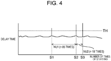
Fig. 4 is a graph illustrating a plurality of delay times acquired by a controller of a welding device according to a first modification of the exemplary embodiment. - Hereinafter, an exemplary embodiment of the present disclosure is described with reference to the drawings. The following description of a preferable exemplary embodiment is merely illustrative in nature and is not intended to limit the present disclosure, application thereof, or use thereof.
-
Fig. 1 illustrateswelding device 10 according to the exemplary embodiment of the present disclosure.Welding device 10 performs tungsten inert gas (TIG) welding by generating arc A betweentungsten electrode 21 mounted onwelding torch 20 andbase material 30 that forms a welding target. Specifically,welding device 10 includesinput circuit unit 11,gas control device 12, high frequencyvoltage application unit 13, weldingoutput circuit unit 14,current detection unit 15, displaydata storage unit 16,display unit 17 that forms an output unit,controller 18, and delaytime storage unit 19. -
Input circuit unit 11 outputs welding instruction signal S1 indicating an ON/OFF state ofswitch 22 mounted onwelding torch 20. - When
controller 18 starts outputting gas supply signal S2 togas control device 12,gas control device 12 makeswelding torch 20 start jetting of a shielding gas tobase material 30. As the shield gas, for example, an argon gas or the like is used.Gas control device 12 is connected towelding torch 20 by way ofgas hose 23. - When
controller 18 outputs high frequency voltage application signal S3 to high frequencyvoltage application unit 13, high frequencyvoltage application unit 13 applies a high frequency high voltage betweentungsten electrode 21 andbase material 30. - Welding
output circuit unit 14 controls a welding voltage and a welding current based on welding control signal S4 output fromcontroller 18. Weldingoutput circuit unit 14 is electrically connected towelding torch 20 viawelding output cable 24. -
Current detection unit 15 detects a welding current more than or equal to a predetermined current threshold. As a specific operation,current detection unit 15 outputs current detection signal S5 when a welding current exceeds the current threshold. - Display
data storage unit 16 stores image data of an image to be output and displayed ondisplay unit 17. The image data to be stored includes image data of first to fourth warning images as an output. The first warning image displays a message that "The electrode is getting smeared.", the second warning image displays a message that "The electrode is worn so that there is a possibility that the generation of an arc does not start.", and the third warning image displays a message that "The electrode is largely worn and smeared. Polishing of the electrode is recommended". The fourth warning image displays a message that "Please polish or exchange the electrode.". -
Display unit 17 is, for example, a display.Display unit 17 outputs and displays an image based on image data stored in displaydata storage unit 16. -
Controller 18 selectively performs a control between a control in an AC output mode where welding control signal S4 is outputted to weldingoutput circuit unit 14 in such a manner that a welding voltage and a welding current become an alternating current voltage and an alternating current respectively, and a control in a DC output mode where welding control signal S4 is output to weldingoutput circuit unit 14 in such a manner that a welding voltage and a welding current become a direct current voltage and a direct current respectively. -
Controller 18 starts outputting of gas supply signal S2 when switch 22 ofwelding torch 20 is switched from an OFF state to an ON state so that welding instruction signal S1 output frominput circuit unit 11 is switched from a signal indicating an OFF state to a signal indicating an ON state. - In addition, when predetermined preflow time Tp has elapsed from a point of time that outputting of gas supply signal S2 is started, controller 18 outputs high frequency voltage application signal S3 at timing t2 so as to perform a start operation where high frequency
voltage application unit 13 is made to start application of a high frequency high voltage. Then, at this point of time that the voltage applying operation is started,controller 18 acquires delay time Tl (seeFig. 2 ) from a point of time that the start operation is started to a point of time that the detection of a welding current more than or equal to the current threshold bycurrent detection unit 15 is started, and stores delay time Tl in delaytime storage unit 19. Then,controller 18 references delay times Tl at a plurality of points of time at which the start operation is performed including a current point of time at which the start operation is performed that are stored in delaytime storage unit 19, and determines whether or not delay times Tl at the plurality of points of time at each of which the start operation is performed satisfy a predetermined time condition. Then,controller 18 performs processing at an abnormal time in a case where delay times Tl satisfy the predetermined time condition. - The time condition is that the first number N1 (being 2 or more) of times of delay times Tl each of which exceeds a predetermined time threshold are included in delay times Tl at a plurality of recent number of points of time at which the start operation is performed. The time condition is stored in
controller 18.Controller 18 changes the time condition by changing the time threshold in accordance with predetermined setting conditions. The setting conditions are an instruction value of a welding current, a flow rate of a shielding gas, a tip angle oftungsten electrode 21, the dopant concentration intungsten electrode 21, a diameter oftungsten electrode 21, and a mode that is either an AC output mode or a DC output mode. - The processing at an abnormal time is processing where
controller 18 makesdisplay unit 17 output and display any one of first to fourth warning images based on image data stored in displaydata storage unit 16. Specifically, in a case where the number LN of delay times Tl each of which exceeds the predetermined time threshold is more than or equal to the first number N1 and less than a predetermined second number N2 among delay times Tl at a plurality of recently-set number of points of time that the start operation is performed, the processing to be performed at an abnormal time becomes a process wherecontroller 18 makesdisplay unit 17 output and display the first warning image. The second number N2 is a value larger than the first number N1. Specifically, in a case where the number LN of delay times Tl each of which exceeds the predetermined time threshold is more than or equal to the second number N2 and less than a predetermined third number N3 among delay times Tl at the plurality of recently-set number of points of time that the start operation is performed, the processing at an abnormal time becomes a process wherecontroller 18 makesdisplay unit 17 output and display the second warning image. The third number N3 is a value larger than the second number N2. In a case where the number of delay times Tl each of which exceeds the predetermined time threshold is more than or equal to the third number N3 and less than a predetermined fourth number N4 among delay times Tl at a plurality of recently-set number of points of time that the start operation is performed, the processing at an abnormal time becomes a process wherecontroller 18 makesdisplay unit 17 output and display the third warning image. The fourth number N4 is a value larger than the third number N3. In a case where the number of delay times Tl each of which exceeds the predetermined time threshold is more than or equal to the fourth number N4 among delay times Tl at a plurality of recently-set number of points of time that the start operation is performed, the processing at an abnormal time becomes a process wherecontroller 18 makesdisplay unit 17 output and display the fourth warning image. The time thresholds and the first to fourth numbers N1 to N4 are set to appropriate values by experiments in advance. - In the exemplary embodiment, the above-mentioned set number of points of time that the start operation is performed is set to 100, and the numbers of the first to fourth numbers N1 to N4 are set to 10, 20, 30 and 40 in this order. However, provided that the set number of points of time that the start operation is performed is larger than the first to fourth numbers N1 to N4, the set number of points of time may be set to the number other than 100. Further, the numbers of first to fourth numbers N1 to N4 may also be set to other numbers provided that a relationship described in the following expression 1 is established.

- Further,
controller 18 controls weldingoutput circuit unit 14 based on welding control signal S4 in such a manner that, from a point of time that a welding current that is more than or equal to the current threshold is detected bycurrent detection unit 15 to a point of time that predetermined hot start period Th (seeFig. 2 ) has elapsed, the welding current assumes a predetermined hot start set current value. - The functions of
controller 18 are implemented by a central processing unit (CPU) and a storage device. - Delay
time storage unit 19 stores delay time Tl from a point of time that the start operation is started to a point of time that the detection of a welding current that is more than or equal to the above-described current threshold is performed bycurrent detection unit 15. - Hereinafter, an example of the operation of
welding device 10 when a switch is switched from an OFF state to an ON state is described with reference to a timing chart illustrated inFig. 2 . - First, when an operator turns on
switch 22 ofwelding torch 20 at timing t1,input circuit unit 11 outputs welding instruction signal S1 that indicates thatinput circuit unit 11 is in an ON state. In response to welding instruction signal S1,controller 18 starts outputting of gas supply signal S2, andgas control device 12 makeswelding torch 20 start jetting of a shield gas tobase material 30. Thereafter, when predetermined preflow time Tp has elapsed from a point of time that outputting of gas supply signal S2 bycontroller 18 is started,controller 18 outputs high frequency voltage application signal S3 at timing t2 so as to perform a start operation where high frequencyvoltage application unit 13 is made to start application of the high frequency high voltage. Thereafter, an insulation betweentungsten electrode 21 andbase material 30 is broken by a high frequency voltage applied by high frequencyvoltage application unit 13. Accordingly, arc A is generated so that a welding current flows, andcurrent detection unit 15 detects a welding current more than or equal to a predetermined current threshold at timing t3. Then,controller 18 acquires delay time Tl from a point of time that the start operation is started to a point of time thatcurrent detection unit 15 detects a welding current more than or equal to the current threshold, and stores acquired delay time Tl. Further,controller 18 controls weldingoutput circuit unit 14 in such a manner that, from a point of time that a welding current that is more than or equal to the current threshold is detected bycurrent detection unit 15 to a point of time that predetermined hot start period Th has elapsed, the welding current assumes a predetermined hot start set current value. -
Fig. 3 is a flowchart for describing detailed processing performed bycontroller 18 whenswitch 22 is switched from an OFF state to an ON state. - When
switch 22 is switched from an OFF state to an ON state so that welding instruction signal S1 output frominput circuit unit 11 is switched from a signal indicating an OFF state to a signal indicating an ON state,controller 18 starts outputting of gas supply signal S2 in S101. - Next, in S102,
controller 18 waits for a lapse of predetermined preflow time Tp from a point of time that outputting of gas supply signal S2 is started in S101. Then, when predetermined preflow time Tp has elapsed from a point of time that the outputting of gas supply signal S2 is started in S101, in S103,controller 18 performs a start operation by outputting high frequency voltage application signal S3 so as to make high frequencyvoltage application unit 13 start application of a high frequency high voltage. - Next, in S104,
controller 18 acquires delay time Tl from a point of time that the start operation is started in S103 to a point of time that a welding current more than or equal to the current threshold is detected bycurrent detection unit 15, andcontroller 18 stores delay time Tl in delaytime storage unit 19. - Then, in S105,
controller 18 refers to delay times Tl at recent 100 points of time at which the start operation is performed that are stored in delaytime storage unit 19, and determines whether or not the time condition that the first number N1, that is, 10 or more delay times Tl each of which exceeds the predetermined time threshold are included in the recent 100 points of time at which the start operation is performed. In a case where the first number N1 or more of delay times Tl that exceeds the predetermined time threshold are not included so that the time condition is not satisfied, the processing advances to S106. On the other hand, in a case where the first number N1 or more of delay times Tl that exceeds the predetermined time threshold are included so that the time condition is satisfied, the processing advances to S107. - In S106,
controller 18 does not perform the processing at an abnormal time. - Then, in S107,
controller 18 refers to delay times Tl at recent 100 points of time at which the start operation is performed that are stored in delaytime storage unit 19, and determines whether or not the number LN of delay times Tl that exceeds the predetermined time threshold is the second number N2, that is, less than 20 among delay times Tl at the recent 100 points of time at which the start operation is performed. When the number LN of the delay times Tl that exceeds the predetermined time threshold is less than the second number N2, the processing advances to S108. On the other hand, when the number LN of the delay times exceeding the predetermined time threshold is more than or equal to the second number N2, the processing advances to S109. - In S108,
controller 18 performs processing of outputting and displaying a first warning image that displays a message that "The electrode is getting smeared." ondisplay unit 17 as the processing at an abnormal time. - Then, in S109,
controller 18 refers to delay times Tl at recent 100 points of time at which the start operation is performed that are stored in delaytime storage unit 19, and determines whether or not the number LN of delay times Tl that exceeds the predetermined times threshold is the third number N3, that is, less than 30 among delay times Tl at the recent 100 points of time at which the start operation is performed. When the number LN of delay times Tl exceeding the predetermined time threshold is less than the third number N3, the processing advances to S110. On the other hand, when the number LN of delay times Tl exceeding the predetermined time threshold is more than or equal to the third number N3, the processing advances to S111. - In S110,
controller 18 performs processing of outputting and displaying a second warning image that "The electrode is worn so that there is a possibility that the generation of an arc does not start." on thedisplay unit 17 as the processing at an abnormal time. - In S111,
controller 18 refers to delay times Tl at recent 100 points of time at which the start operation is performed that are stored in delaytime storage unit 19, and determines whether or not the number LN of delay times Tl that exceeds the predetermined time threshold is the fourth number N4, that is, less than 40 among delay times Tl at the recent 100 points of time at which the start operation is performed. When the number LN of delay times Tl exceeding the predetermined time threshold is less than the fourth number N4, the processing advances to S112. On the other hand, when the number LN of delay times Tl exceeding the predetermined time threshold is more than or equal to the fourth number N4, the processing advances to S113. - In S112,
controller 18 performs processing of making thedisplay unit 17 output and display a third warning image "Wear of the electrode is large and smear on the electrode is large. Polishing of the electrode is recommended." as the processing at an abnormal time. - In S113,
controller 18 performs processing of makingdisplay unit 17 output and display the fourth warning image that "Please polish or exchange the electrode." as the processing at an abnormal time. - In general, when
tungsten electrode 21 is worn or smeared, it becomes difficult to shift an operation state to an arc discharge state, and the time from the generation of the high frequency voltage to the start of the flow of the welding current, that is, the delay time Tl becomes long. In the exemplary embodiment, when the frequency at which the delay time Tl exceeds the time threshold becomes high,controller 18 performs the processing at an abnormal time, anddisplay unit 17 displays the first to fourth warning images. Accordingly, an operator can recognize the consumption or a smear ontungsten electrode 21, and can take a measure such as polishingtungsten electrode 21 or exchangingtungsten electrode 21. Therefore, it is possible to suppress the occurrence of a state where starting of an arc takes an excessively long time or starting of an arc cannot be performed due to consumption or smear ontungsten electrode 21. - The controller determines whether or not the processing at an abnormal time should be performed based on the delay times Tl at a plurality of points of time at which the start operation is performed. Accordingly, compared with the case where the controller determines whether or not the processing at an abnormal time should be performed based on the delay time at a point of time at which the start operation is performed one time as described in PTL 1, the processing at an abnormal time is minimally performed due to a temporary factor other than the consumption and the smear on
tungsten electrode 21. Therefore, unnecessary polishing or exchange oftungsten electrode 21 can be suppressed. - In a first modification of the present exemplary embodiment, the time condition is that delay time Tl in the current start operation exceeds predetermined threshold TH (see
Fig. 4 ), and the number of times of the start operation performed between the current start operation and the previous start operation in which the delay time Tl exceeds the threshold TH is less than a predetermined reference number of times. In the first modification, the reference number of times is set to 20 times. However, the reference number of times may be set to another number of times. In addition, the processing at an abnormal time is always processing in which the first warning image is output to and displayed ondisplay unit 17. - For example, in an example illustrated in
Fig. 4 , delay time Tl exceeds threshold TH in the S1-th start operation, the S2 (= S1 + 86)-th start operation, and the S3 (= S2 + 19)-th start operation. In this case, at the point of time that the S2-th start operation is performed, the number of times NU1 of the start operations performed between the current start operation and the previous start operation in which the delay time Tl exceeds the threshold TH, that is, the S1-th start operation is 20 times or more, that is, 85 times, and the time condition is not satisfied. Therefore,controller 18 does not make thedisplay unit 17 output and display the first warning image. - On the other hand, at the point of time that the S3-th start operation is performed, the number of times NU2 of the start operations performed between the current start operation and the previous start operation in which the delay time Tl exceeds threshold TH, that is, the S2-th start operation is less than 20 times, that is, 18 times, and the time condition is satisfied. Therefore,
controller 18 makesdisplay unit 17 output and display the first warning image. - Other configurations and operations are the same as the configurations and the operations in the above exemplary embodiment and hence, the detailed description thereof will be omitted.
- Also in a second modification of the exemplary embodiment, the processing at an abnormal time is always processing in which the first warning image is output and displayed on
display unit 17. - In addition, the time condition satisfies at least one among a first condition that the delay time Tl in the current start operation exceeds the predetermined first time threshold, a second condition that the number of delay times Tl that exceed the predetermined second time threshold is included in delay times Tl at a plurality of recently-set points of time including the present time at which the start operation is performed, and the number of such delay times Tl is more than or equal to a predetermined reference number, and a third condition that delay time Tl at the current start operation exceeds the predetermined third time threshold and the number of the start operations performed between the current start operation and the previous start operation in which delay time Tl exceeds a third time threshold becomes less than a predetermined reference number of times. The first to third time thresholds are set so as to satisfy the following expression 2.

- Other configurations and operations are the same as the configurations and the operations in the above exemplary embodiment and hence, the detailed description thereof will be omitted.
- Also in a third modification of the exemplary embodiment, the processing at an abnormal time always is processing where
controller 18 makesdisplay unit 17 output and display the first warning image. - Further, the time condition is that the variance of delay times Tl that are acquired at a plurality of recently-set number of points of time at which the start operation is performed becomes more than or equal to a predetermined value. The set number of times is, for example, 100 times. When the wear and the smear on
tungsten electrode 21 are small, delay time Tl is relatively constant. Accordingly, the variance becomes small. However, along with the increase of wear and smear ontungsten electrode 21, the variance is increased. Accordingly, the wear and the smear ontungsten electrode 21 can be estimated based on the variance. - Other configurations and operations are the same as the configurations and the operations in the above exemplary embodiment and hence, the detailed description thereof will be omitted.
- The processing at an abnormal time may be processing where any one of the first to fourth warning images is selected, and is output and displayed corresponding to a value of the variance.
- In a fourth modification of the exemplary embodiment,
controller 18 performs processing where a hot start set current value is changed to a larger current value as a processing at an abnormal time in place of the processing where any one of the first to fourth warning images is output to and is displayed ondisplay unit 17. As a result,tungsten electrode 21 can be warmed faster. The hot start set current value is increased to such an extent thattungsten electrode 21 is not excessively consumed. - Other configurations and operations are the same as the configurations and the operations in the above exemplary embodiment and hence, the detailed description thereof will be omitted.
- The time condition is not limited to the conditions described in the above-described exemplary embodiment and the first to fourth modifications of the exemplary embodiment. Other appropriate conditions may be set by experiments. In the above-described exemplary embodiment and the first to fourth modifications, the time condition is set in such a manner that when delay times at a plurality of previous points of time at which the start operation is performed before the current time are input to a predetermined function, an output value of the function satisfies a predetermined numerical value condition. However, the time condition may be set in such a manner that when delay times at a plurality of previous points of time of start operation before the current time are input to artificial intelligence (AI), an output of the AI satisfies a predetermined condition.
- Further, in the fourth modification of the above-described exemplary embodiment, the processing at an abnormal time is set to the processing where a hot start set current value is increased. However, the processing at an abnormal time may be set to processing where an after-flow time during which a shielding gas is continuously released after finishing of welding is prolonged. Further, the processing at an abnormal time may be set to processing where other parameters such as a frequency of an output during an operation in an AC output mode are changed.
- Further, as the processing at an abnormal time,
controller 18 may perform both the processing where a hot start set current value is increased and the processing wherecontroller 18 makesdisplay unit 17 output and display the warning image. - Further, the processing at an abnormal time is not limited to the processing where
controller 18 makesdisplay unit 17 output an image, and may make a voice output device output a voice. - In the above-described exemplary embodiment,
controller 18 changes the time condition in accordance with six setting conditions consisting of: an instruction value of a welding current, a flow rate of a shielding gas, a tip end angle oftungsten electrode 21, the dopant concentration intungsten electrode 21, a diameter oftungsten electrode 21, and whether the mode is an alternating current (AC) output mode or a direct current (DC) output mode. However, the time condition may be changed in accordance with only a part of at least one of the six setting conditions. The time condition may not be changed. - The welding device of the present disclosure can suppress the performing of processing at an abnormal time due to a temporary factor other than wear of the tungsten electrode and the formation of smear on the tungsten electrode. The welding device of the present disclosure is useful as a welding device that performs welding by generating an arc between the tungsten electrode and the welding target.
-
- 10
- welding device
- 13
- high frequency voltage application unit
- 14
- welding output circuit unit
- 15
- current detection unit
- 17
- display unit (output unit)
- 18
- controller
- 21
- tungsten electrode
- 30
- base material (welding target)
- A
- arc
- Tl
- delay time
- Th
- hot start period
- N1
- first number
- N2
- second number
- N3
- third number
- N4
- fourth number
- NU1, NU2
- number of times
Claims (7)
- A welding device that is configured to perform welding by generating an arc between a tungsten electrode and a welding target, the welding device comprising:a high frequency voltage application unit configured to apply a high frequency voltage between the tungsten electrode and the welding target;a welding output circuit unit configured to control a welding current;a current detection unit configured to detect the welding current that is more than or equal to a predetermined current threshold; anda controller configured, at a time of performing a start operation for making the high frequency voltage application unit start applying of the high frequency voltage, to acquire a delay time from a point of time that the start operation is performed to a point of time that the welding current is detected by the current detection unit, to determine whether or not delay times corresponding to the delay time that are acquired at a plurality of previous points of time at which the start operation is performed satisfy a predetermined time condition, and to perform predetermined processing at an abnormal time in a case where the delay times satisfy the predetermined time condition.
- The welding device according to Claim 1, wherein
the time condition is that a predetermined number including two or more of the delay times each of which exceeds a predetermined time threshold are included in the delay times at a predetermined plurality of set number of points of time at which the start operation is performed. - The welding device according to Claim 1, wherein
the time condition is that the delay time at the start operation of the present time exceeds a predetermined threshold, and the number of times of the start operations performed between the start operation of the present time and the start operation of a previous time where the delay time exceeds the predetermined threshold is less than a predetermined reference number of times. - The welding device according to Claim 1, wherein
the time condition is that variance of the delay times at the plurality of points of time at which the start operation is performed becomes more than or equal to a predetermined value. - The welding device according to any one of Claims 1 to 4, wherein
the time condition is changed in accordance with at least one setting condition selected from a group consisting of an instruction value of a welding current, a flow rate of a shielding gas, a tip end angle of a tungsten electrode, a dopant concentration in the tungsten electrode, a diameter of the tungsten electrode, and whether a mode is an alternating current output mode or a direct current output mode. - The welding device according to any one of Claims 1 to 5, whereinthe controller is configured to control the welding output circuit unit so as to set the welding current to a predetermined hot start set current value from a point of time that the welding current is detected by the current detection unit to a point of time that a predetermined hot start period has elapsed, andthe processing at an abnormal time is processing where the hot start set current value is changed to a larger value.
- The welding device according to any one of Claims 1 to 6, further comprising:an output unit configured to perform predetermined outputting, whereinthe output unit is configured to be made to perform the predetermined outputting in the processing at an abnormal time.
Applications Claiming Priority (2)
| Application Number | Priority Date | Filing Date | Title |
|---|---|---|---|
| JP2020009392 | 2020-01-23 | ||
| PCT/JP2021/000955 WO2021149570A1 (en) | 2020-01-23 | 2021-01-14 | Welding device |
Publications (3)
| Publication Number | Publication Date |
|---|---|
| EP4094874A1 true EP4094874A1 (en) | 2022-11-30 |
| EP4094874A4 EP4094874A4 (en) | 2023-08-09 |
| EP4094874B1 EP4094874B1 (en) | 2025-08-06 |
Family
ID=76992255
Family Applications (1)
| Application Number | Title | Priority Date | Filing Date |
|---|---|---|---|
| EP21743742.5A Active EP4094874B1 (en) | 2020-01-23 | 2021-01-14 | Welding device |
Country Status (4)
| Country | Link |
|---|---|
| EP (1) | EP4094874B1 (en) |
| JP (1) | JP7595239B2 (en) |
| CN (1) | CN114929420B (en) |
| WO (1) | WO2021149570A1 (en) |
Cited By (1)
| Publication number | Priority date | Publication date | Assignee | Title |
|---|---|---|---|---|
| CN116275673A (en) * | 2023-03-21 | 2023-06-23 | 深圳市正浩创新科技股份有限公司 | Welding detection method, welding system and electronic equipment |
Families Citing this family (3)
| Publication number | Priority date | Publication date | Assignee | Title |
|---|---|---|---|---|
| CN114131155B (en) * | 2021-12-10 | 2023-09-22 | 唐山松下产业机器有限公司 | Welding device and tungsten electrode cleaning method |
| CN116441673B (en) * | 2023-06-14 | 2023-08-22 | 苏芯物联技术(南京)有限公司 | Intelligent dynamic control method for welding shielding gas flow rate in argon arc welding scene |
| CN116921817B (en) * | 2023-09-15 | 2023-12-15 | 中建安装集团有限公司 | Automatic TIG welding arc concentration online monitoring and intelligent early warning method |
Family Cites Families (23)
| Publication number | Priority date | Publication date | Assignee | Title |
|---|---|---|---|---|
| US3597580A (en) * | 1969-04-25 | 1971-08-03 | Chemetron Corp | Controlled rectifier arc welding supply having improved positive firing characteristics |
| US4151395A (en) * | 1976-07-06 | 1979-04-24 | CRC-Crose, International, Inc. | Method and apparatus for electric arc and analogous welding under precision control |
| JPS59153577A (en) * | 1983-02-21 | 1984-09-01 | Mitsubishi Electric Corp | Consumable electrode type arc welding device |
| JPS61147972A (en) * | 1984-12-19 | 1986-07-05 | Matsushita Electric Ind Co Ltd | Power source for consumable electrode type welding |
| JP3110135B2 (en) * | 1992-03-17 | 2000-11-20 | 松下電器産業株式会社 | Control method of consumable electrode type AC arc welding machine |
| JPH07276075A (en) * | 1994-04-05 | 1995-10-24 | Kubota Corp | Abnormality detection method during welding |
| JP3110295B2 (en) * | 1995-10-24 | 2000-11-20 | 松下電器産業株式会社 | Control method of consumable electrode type AC arc welding machine |
| JP2002203839A (en) * | 2001-01-04 | 2002-07-19 | Hitachi Ltd | Plasma processing equipment |
| JP4558227B2 (en) | 2001-03-07 | 2010-10-06 | 株式会社三社電機製作所 | Welding power supply |
| JP2003245774A (en) * | 2002-02-26 | 2003-09-02 | Daihen Corp | Consumable electrode arc welding method and arc welding set, and arc welding robot |
| JP4098279B2 (en) * | 2004-07-05 | 2008-06-11 | セイコーインスツル株式会社 | Battery protection circuit |
| JP3844004B1 (en) * | 2005-05-31 | 2006-11-08 | 松下電器産業株式会社 | Pulse arc welding control method and pulse arc welding apparatus |
| AT503469B1 (en) * | 2006-04-12 | 2008-03-15 | Fronius Int Gmbh | WELDING |
| FR2906169B1 (en) * | 2006-09-25 | 2009-06-05 | Air Liquide | METHOD FOR AUTOMATICALLY DETECTING THE WEAR OF A WELDING ELECTRODE |
| US10086461B2 (en) * | 2009-01-13 | 2018-10-02 | Lincoln Global, Inc. | Method and system to start and use combination filler wire feed and high intensity energy source for welding |
| JP5325085B2 (en) * | 2009-12-24 | 2013-10-23 | 日本碍子株式会社 | Connection device |
| JP5167237B2 (en) | 2009-12-24 | 2013-03-21 | トヨタ自動車株式会社 | Rotation sensor abnormality determination device |
| JP5411186B2 (en) | 2011-03-18 | 2014-02-12 | アイシン精機株式会社 | Grill shutter control device |
| AT513828B1 (en) * | 2013-04-22 | 2014-08-15 | Fronius Int Gmbh | Method and apparatus for simulating an electrode welding process |
| CN104096947B (en) * | 2014-03-12 | 2015-12-30 | 深圳市瑞凌实业股份有限公司 | Carbon dioxide gas shielded welding machine and employing digit pulse control the method for striking |
| WO2017169409A1 (en) | 2016-03-29 | 2017-10-05 | パナソニックIpマネジメント株式会社 | Welding device and welding method |
| EP3512092B1 (en) * | 2016-09-08 | 2020-09-30 | Panasonic Intellectual Property Management Co., Ltd. | Motor control device, motor position control method, and industrial machine |
| WO2018207392A1 (en) * | 2017-05-10 | 2018-11-15 | 株式会社アマダミヤチ | Tig welding method and tig welding device |
-
2021
- 2021-01-14 JP JP2021573100A patent/JP7595239B2/en active Active
- 2021-01-14 EP EP21743742.5A patent/EP4094874B1/en active Active
- 2021-01-14 CN CN202180008818.6A patent/CN114929420B/en active Active
- 2021-01-14 WO PCT/JP2021/000955 patent/WO2021149570A1/en not_active Ceased
Cited By (1)
| Publication number | Priority date | Publication date | Assignee | Title |
|---|---|---|---|---|
| CN116275673A (en) * | 2023-03-21 | 2023-06-23 | 深圳市正浩创新科技股份有限公司 | Welding detection method, welding system and electronic equipment |
Also Published As
| Publication number | Publication date |
|---|---|
| JP7595239B2 (en) | 2024-12-06 |
| CN114929420B (en) | 2024-04-05 |
| WO2021149570A1 (en) | 2021-07-29 |
| CN114929420A (en) | 2022-08-19 |
| EP4094874B1 (en) | 2025-08-06 |
| EP4094874A4 (en) | 2023-08-09 |
| JPWO2021149570A1 (en) | 2021-07-29 |
Similar Documents
| Publication | Publication Date | Title |
|---|---|---|
| EP4094874B1 (en) | Welding device | |
| EP2436471B1 (en) | Arc welding device and arc welding system | |
| US10259067B2 (en) | Remote polarity detection and control for welding process | |
| EP2716254B1 (en) | Dental handpiece control device | |
| EP3219428B1 (en) | Arc welding control method | |
| EP1745880A2 (en) | Consumable electrode arc-welding machine | |
| US6031203A (en) | Method and apparatus for determining stability of arc welding | |
| US9421626B2 (en) | Apparatus and method for electrical discharge machining modulation control | |
| EP1283088A1 (en) | Apparatus and method for assessing the state of wear of electrode tips used in consumable electrode gas shield arc welding | |
| JP2007149596A (en) | Arc detector of plasma treatment system | |
| CN113727800B (en) | Arc welding control method and arc welding device | |
| JP6410915B1 (en) | Electrical equipment and method for detecting grounding state of electrical equipment | |
| JP4465232B2 (en) | Static elimination control method of static eliminator | |
| EP2985105A1 (en) | Wire electric discharge machine determining whether or not electrical discharge machining of workpiece can be perfomed | |
| EP2921849B1 (en) | Protecting tube deterioration detecting apparatus and method therefor | |
| CN107078070B (en) | Ball forming device for wire bonding | |
| JP2024099058A (en) | Arc welding method and arc welding device | |
| JP4637675B2 (en) | Lamp lighting device | |
| JP6821902B2 (en) | Thermal processing torch, power supply, wire feeder, and thermal processing system | |
| JPWO2015118808A1 (en) | Arc welding apparatus and arc welding method | |
| US20200306861A1 (en) | Tip saver for a welding system | |
| EP4026667B1 (en) | Welding machine and welding system provided with a plurality of welding machines | |
| US20240399485A1 (en) | Welding-type power supplies and systems having multiple sources of input power | |
| JP2015058443A (en) | Plasma arc welding system | |
| JP2024066123A (en) | Arc welding device and arc welding method |
Legal Events
| Date | Code | Title | Description |
|---|---|---|---|
| STAA | Information on the status of an ep patent application or granted ep patent |
Free format text: STATUS: THE INTERNATIONAL PUBLICATION HAS BEEN MADE |
|
| PUAI | Public reference made under article 153(3) epc to a published international application that has entered the european phase |
Free format text: ORIGINAL CODE: 0009012 |
|
| STAA | Information on the status of an ep patent application or granted ep patent |
Free format text: STATUS: REQUEST FOR EXAMINATION WAS MADE |
|
| 17P | Request for examination filed |
Effective date: 20220616 |
|
| AK | Designated contracting states |
Kind code of ref document: A1 Designated state(s): AL AT BE BG CH CY CZ DE DK EE ES FI FR GB GR HR HU IE IS IT LI LT LU LV MC MK MT NL NO PL PT RO RS SE SI SK SM TR |
|
| DAV | Request for validation of the european patent (deleted) | ||
| DAX | Request for extension of the european patent (deleted) | ||
| A4 | Supplementary search report drawn up and despatched |
Effective date: 20230706 |
|
| RIC1 | Information provided on ipc code assigned before grant |
Ipc: B23K 9/167 20060101ALI20230630BHEP Ipc: B23K 9/10 20060101ALI20230630BHEP Ipc: B23K 9/067 20060101AFI20230630BHEP |
|
| GRAP | Despatch of communication of intention to grant a patent |
Free format text: ORIGINAL CODE: EPIDOSNIGR1 |
|
| STAA | Information on the status of an ep patent application or granted ep patent |
Free format text: STATUS: GRANT OF PATENT IS INTENDED |
|
| INTG | Intention to grant announced |
Effective date: 20240926 |
|
| GRAJ | Information related to disapproval of communication of intention to grant by the applicant or resumption of examination proceedings by the epo deleted |
Free format text: ORIGINAL CODE: EPIDOSDIGR1 |
|
| STAA | Information on the status of an ep patent application or granted ep patent |
Free format text: STATUS: REQUEST FOR EXAMINATION WAS MADE |
|
| GRAP | Despatch of communication of intention to grant a patent |
Free format text: ORIGINAL CODE: EPIDOSNIGR1 |
|
| STAA | Information on the status of an ep patent application or granted ep patent |
Free format text: STATUS: GRANT OF PATENT IS INTENDED |
|
| INTC | Intention to grant announced (deleted) | ||
| INTG | Intention to grant announced |
Effective date: 20250228 |
|
| GRAS | Grant fee paid |
Free format text: ORIGINAL CODE: EPIDOSNIGR3 |
|
| GRAA | (expected) grant |
Free format text: ORIGINAL CODE: 0009210 |
|
| STAA | Information on the status of an ep patent application or granted ep patent |
Free format text: STATUS: THE PATENT HAS BEEN GRANTED |
|
| AK | Designated contracting states |
Kind code of ref document: B1 Designated state(s): AL AT BE BG CH CY CZ DE DK EE ES FI FR GB GR HR HU IE IS IT LI LT LU LV MC MK MT NL NO PL PT RO RS SE SI SK SM TR |
|
| REG | Reference to a national code |
Ref country code: GB Ref legal event code: FG4D |
|
| REG | Reference to a national code |
Ref country code: CH Ref legal event code: EP |
|
| REG | Reference to a national code |
Ref country code: IE Ref legal event code: FG4D |
|
| REG | Reference to a national code |
Ref country code: DE Ref legal event code: R096 Ref document number: 602021035646 Country of ref document: DE |
|
| REG | Reference to a national code |
Ref country code: NL Ref legal event code: MP Effective date: 20250806 |
|
| PG25 | Lapsed in a contracting state [announced via postgrant information from national office to epo] |
Ref country code: IS Free format text: LAPSE BECAUSE OF FAILURE TO SUBMIT A TRANSLATION OF THE DESCRIPTION OR TO PAY THE FEE WITHIN THE PRESCRIBED TIME-LIMIT Effective date: 20251206 |
|
| PG25 | Lapsed in a contracting state [announced via postgrant information from national office to epo] |
Ref country code: NO Free format text: LAPSE BECAUSE OF FAILURE TO SUBMIT A TRANSLATION OF THE DESCRIPTION OR TO PAY THE FEE WITHIN THE PRESCRIBED TIME-LIMIT Effective date: 20251106 |
|
| REG | Reference to a national code |
Ref country code: LT Ref legal event code: MG9D |
|
| PG25 | Lapsed in a contracting state [announced via postgrant information from national office to epo] |
Ref country code: PT Free format text: LAPSE BECAUSE OF FAILURE TO SUBMIT A TRANSLATION OF THE DESCRIPTION OR TO PAY THE FEE WITHIN THE PRESCRIBED TIME-LIMIT Effective date: 20251209 |
|
| PG25 | Lapsed in a contracting state [announced via postgrant information from national office to epo] |
Ref country code: FI Free format text: LAPSE BECAUSE OF FAILURE TO SUBMIT A TRANSLATION OF THE DESCRIPTION OR TO PAY THE FEE WITHIN THE PRESCRIBED TIME-LIMIT Effective date: 20250806 |
|
| PG25 | Lapsed in a contracting state [announced via postgrant information from national office to epo] |
Ref country code: HR Free format text: LAPSE BECAUSE OF FAILURE TO SUBMIT A TRANSLATION OF THE DESCRIPTION OR TO PAY THE FEE WITHIN THE PRESCRIBED TIME-LIMIT Effective date: 20250806 Ref country code: NL Free format text: LAPSE BECAUSE OF FAILURE TO SUBMIT A TRANSLATION OF THE DESCRIPTION OR TO PAY THE FEE WITHIN THE PRESCRIBED TIME-LIMIT Effective date: 20250806 |
|
| PG25 | Lapsed in a contracting state [announced via postgrant information from national office to epo] |
Ref country code: GR Free format text: LAPSE BECAUSE OF FAILURE TO SUBMIT A TRANSLATION OF THE DESCRIPTION OR TO PAY THE FEE WITHIN THE PRESCRIBED TIME-LIMIT Effective date: 20251107 |
|
| PG25 | Lapsed in a contracting state [announced via postgrant information from national office to epo] |
Ref country code: SE Free format text: LAPSE BECAUSE OF FAILURE TO SUBMIT A TRANSLATION OF THE DESCRIPTION OR TO PAY THE FEE WITHIN THE PRESCRIBED TIME-LIMIT Effective date: 20250806 |
|
| PG25 | Lapsed in a contracting state [announced via postgrant information from national office to epo] |
Ref country code: LV Free format text: LAPSE BECAUSE OF FAILURE TO SUBMIT A TRANSLATION OF THE DESCRIPTION OR TO PAY THE FEE WITHIN THE PRESCRIBED TIME-LIMIT Effective date: 20250806 |
|
| PG25 | Lapsed in a contracting state [announced via postgrant information from national office to epo] |
Ref country code: PL Free format text: LAPSE BECAUSE OF FAILURE TO SUBMIT A TRANSLATION OF THE DESCRIPTION OR TO PAY THE FEE WITHIN THE PRESCRIBED TIME-LIMIT Effective date: 20250806 Ref country code: BG Free format text: LAPSE BECAUSE OF FAILURE TO SUBMIT A TRANSLATION OF THE DESCRIPTION OR TO PAY THE FEE WITHIN THE PRESCRIBED TIME-LIMIT Effective date: 20250806 |
|
| PG25 | Lapsed in a contracting state [announced via postgrant information from national office to epo] |
Ref country code: RS Free format text: LAPSE BECAUSE OF FAILURE TO SUBMIT A TRANSLATION OF THE DESCRIPTION OR TO PAY THE FEE WITHIN THE PRESCRIBED TIME-LIMIT Effective date: 20251106 |
|
| PG25 | Lapsed in a contracting state [announced via postgrant information from national office to epo] |
Ref country code: ES Free format text: LAPSE BECAUSE OF FAILURE TO SUBMIT A TRANSLATION OF THE DESCRIPTION OR TO PAY THE FEE WITHIN THE PRESCRIBED TIME-LIMIT Effective date: 20250806 |
|
| REG | Reference to a national code |
Ref country code: AT Ref legal event code: MK05 Ref document number: 1821254 Country of ref document: AT Kind code of ref document: T Effective date: 20250806 |
|
| PG25 | Lapsed in a contracting state [announced via postgrant information from national office to epo] |
Ref country code: SM Free format text: LAPSE BECAUSE OF FAILURE TO SUBMIT A TRANSLATION OF THE DESCRIPTION OR TO PAY THE FEE WITHIN THE PRESCRIBED TIME-LIMIT Effective date: 20250806 |
|
| PG25 | Lapsed in a contracting state [announced via postgrant information from national office to epo] |
Ref country code: DK Free format text: LAPSE BECAUSE OF FAILURE TO SUBMIT A TRANSLATION OF THE DESCRIPTION OR TO PAY THE FEE WITHIN THE PRESCRIBED TIME-LIMIT Effective date: 20250806 |
|
| PGFP | Annual fee paid to national office [announced via postgrant information from national office to epo] |
Ref country code: DE Payment date: 20260121 Year of fee payment: 6 |
|
| PG25 | Lapsed in a contracting state [announced via postgrant information from national office to epo] |
Ref country code: AT Free format text: LAPSE BECAUSE OF FAILURE TO SUBMIT A TRANSLATION OF THE DESCRIPTION OR TO PAY THE FEE WITHIN THE PRESCRIBED TIME-LIMIT Effective date: 20250806 |
|
| PG25 | Lapsed in a contracting state [announced via postgrant information from national office to epo] |
Ref country code: IT Free format text: LAPSE BECAUSE OF FAILURE TO SUBMIT A TRANSLATION OF THE DESCRIPTION OR TO PAY THE FEE WITHIN THE PRESCRIBED TIME-LIMIT Effective date: 20250806 |
|
| PG25 | Lapsed in a contracting state [announced via postgrant information from national office to epo] |
Ref country code: CZ Free format text: LAPSE BECAUSE OF FAILURE TO SUBMIT A TRANSLATION OF THE DESCRIPTION OR TO PAY THE FEE WITHIN THE PRESCRIBED TIME-LIMIT Effective date: 20250806 |
|
| PG25 | Lapsed in a contracting state [announced via postgrant information from national office to epo] |
Ref country code: EE Free format text: LAPSE BECAUSE OF FAILURE TO SUBMIT A TRANSLATION OF THE DESCRIPTION OR TO PAY THE FEE WITHIN THE PRESCRIBED TIME-LIMIT Effective date: 20250806 Ref country code: SK Free format text: LAPSE BECAUSE OF FAILURE TO SUBMIT A TRANSLATION OF THE DESCRIPTION OR TO PAY THE FEE WITHIN THE PRESCRIBED TIME-LIMIT Effective date: 20250806 |