EP4094849B1 - Electromechanical transducer for generating vibrations to be transmitted to an external mounting wall - Google Patents
Electromechanical transducer for generating vibrations to be transmitted to an external mounting wall Download PDFInfo
- Publication number
- EP4094849B1 EP4094849B1 EP22175305.6A EP22175305A EP4094849B1 EP 4094849 B1 EP4094849 B1 EP 4094849B1 EP 22175305 A EP22175305 A EP 22175305A EP 4094849 B1 EP4094849 B1 EP 4094849B1
- Authority
- EP
- European Patent Office
- Prior art keywords
- curvilinear
- electromechanical transducer
- central
- central portion
- peripheral
- Prior art date
- Legal status (The legal status is an assumption and is not a legal conclusion. Google has not performed a legal analysis and makes no representation as to the accuracy of the status listed.)
- Active
Links
Images


Classifications
-
- H—ELECTRICITY
- H04—ELECTRIC COMMUNICATION TECHNIQUE
- H04R—LOUDSPEAKERS, MICROPHONES, GRAMOPHONE PICK-UPS OR LIKE ACOUSTIC ELECTROMECHANICAL TRANSDUCERS; ELECTRIC HEARING AIDS; PUBLIC ADDRESS SYSTEMS
- H04R23/00—Transducers other than those covered by groups H04R9/00 - H04R21/00
-
- B—PERFORMING OPERATIONS; TRANSPORTING
- B06—GENERATING OR TRANSMITTING MECHANICAL VIBRATIONS IN GENERAL
- B06B—METHODS OR APPARATUS FOR GENERATING OR TRANSMITTING MECHANICAL VIBRATIONS OF INFRASONIC, SONIC, OR ULTRASONIC FREQUENCY, e.g. FOR PERFORMING MECHANICAL WORK IN GENERAL
- B06B1/00—Methods or apparatus for generating mechanical vibrations of infrasonic, sonic, or ultrasonic frequency
- B06B1/02—Methods or apparatus for generating mechanical vibrations of infrasonic, sonic, or ultrasonic frequency making use of electrical energy
- B06B1/04—Methods or apparatus for generating mechanical vibrations of infrasonic, sonic, or ultrasonic frequency making use of electrical energy operating with electromagnetism
- B06B1/045—Methods or apparatus for generating mechanical vibrations of infrasonic, sonic, or ultrasonic frequency making use of electrical energy operating with electromagnetism using vibrating magnet, armature or coil system
-
- B—PERFORMING OPERATIONS; TRANSPORTING
- B06—GENERATING OR TRANSMITTING MECHANICAL VIBRATIONS IN GENERAL
- B06B—METHODS OR APPARATUS FOR GENERATING OR TRANSMITTING MECHANICAL VIBRATIONS OF INFRASONIC, SONIC, OR ULTRASONIC FREQUENCY, e.g. FOR PERFORMING MECHANICAL WORK IN GENERAL
- B06B1/00—Methods or apparatus for generating mechanical vibrations of infrasonic, sonic, or ultrasonic frequency
- B06B1/02—Methods or apparatus for generating mechanical vibrations of infrasonic, sonic, or ultrasonic frequency making use of electrical energy
-
- G—PHYSICS
- G10—MUSICAL INSTRUMENTS; ACOUSTICS
- G10K—SOUND-PRODUCING DEVICES; METHODS OR DEVICES FOR PROTECTING AGAINST, OR FOR DAMPING, NOISE OR OTHER ACOUSTIC WAVES IN GENERAL; ACOUSTICS NOT OTHERWISE PROVIDED FOR
- G10K9/00—Devices in which sound is produced by vibrating a diaphragm or analogous element, e.g. fog horns, vehicle hooters or buzzers
- G10K9/12—Devices in which sound is produced by vibrating a diaphragm or analogous element, e.g. fog horns, vehicle hooters or buzzers electrically operated
- G10K9/13—Devices in which sound is produced by vibrating a diaphragm or analogous element, e.g. fog horns, vehicle hooters or buzzers electrically operated using electromagnetic driving means
-
- H—ELECTRICITY
- H02—GENERATION; CONVERSION OR DISTRIBUTION OF ELECTRIC POWER
- H02K—DYNAMO-ELECTRIC MACHINES
- H02K33/00—Motors with reciprocating, oscillating or vibrating magnet, armature or coil system
- H02K33/16—Motors with reciprocating, oscillating or vibrating magnet, armature or coil system with polarised armatures moving in alternate directions by reversal or energisation of a single coil system
-
- H—ELECTRICITY
- H04—ELECTRIC COMMUNICATION TECHNIQUE
- H04R—LOUDSPEAKERS, MICROPHONES, GRAMOPHONE PICK-UPS OR LIKE ACOUSTIC ELECTROMECHANICAL TRANSDUCERS; ELECTRIC HEARING AIDS; PUBLIC ADDRESS SYSTEMS
- H04R11/00—Transducers of moving-armature or moving-core type
- H04R11/02—Loudspeakers
-
- H—ELECTRICITY
- H04—ELECTRIC COMMUNICATION TECHNIQUE
- H04R—LOUDSPEAKERS, MICROPHONES, GRAMOPHONE PICK-UPS OR LIKE ACOUSTIC ELECTROMECHANICAL TRANSDUCERS; ELECTRIC HEARING AIDS; PUBLIC ADDRESS SYSTEMS
- H04R7/00—Diaphragms for electromechanical transducers; Cones
- H04R7/02—Diaphragms for electromechanical transducers; Cones characterised by the construction
- H04R7/12—Non-planar diaphragms or cones
- H04R7/127—Non-planar diaphragms or cones dome-shaped
-
- H—ELECTRICITY
- H04—ELECTRIC COMMUNICATION TECHNIQUE
- H04R—LOUDSPEAKERS, MICROPHONES, GRAMOPHONE PICK-UPS OR LIKE ACOUSTIC ELECTROMECHANICAL TRANSDUCERS; ELECTRIC HEARING AIDS; PUBLIC ADDRESS SYSTEMS
- H04R7/00—Diaphragms for electromechanical transducers; Cones
- H04R7/16—Mounting or tensioning of diaphragms or cones
- H04R7/18—Mounting or tensioning of diaphragms or cones at the periphery
Definitions
- This invention relates to an electromechanical transducer for generating vibrations to be transmitted to an external mounting wall of the transducer itself.
- Such electromechanical transducers also known in the field as exciters or agitators, or as shakers, are used, for example, to cause an associated body to vibrate so as to generate sounds.
- shakers comprise, inter alia, a vibration generating assembly including a coil, the windings of which have a suitable electrical power supply, and a magnetic circuit functionally associated with the coil, which is configured so as to move along a reference axis relative to the coil, such that, as a whole, the motion is transferred to the surface to be vibrated.
- One essential aspect for the proper operation of a shaker is that it must be ensured that, during the useful life of the shaker, the vibration generation assembly operates with the greatest possible precision, and, in particular, that the magnetic circuit remains aligned with the coil and centered in the desired position, and continues to move with the greatest possible precision along the reference axis, thus avoiding, for example, the generation of undesired noise.
- centring elements which, in practice, behave like springs, are configured so as to permit axial movement of the magnetic circuit, requiring it to move with the greatest possible precision along the reference axis; as such, they commonly comprise a component that is meant to be rigidly affixed to the body of the shaker, a component connected to the magnetic circuit, and a part that deforms elastically so as to ensure adequate useful movement of the magnetic circuit.
- a typical solution provides for a centring element to be affixed by means of a plurality of mounting screws or rivets, as shown, e.g., in patent document KR 20170075249 A .
- this solution is not optimal given the need to first drill holes in various parts of the components to be connected to one another, and then to form the respective attachments.
- This solution also has limited reliability, and may result in undesired failure of the bonds, due, e.g., to the continuous mechanical stresses to which the bonded parts are exposed during their useful life, the variability of operating temperatures, etc.
- US 2015/296280 A1 discloses a bass shaker system that includes a motor and a motor housing, where the motor includes a motor case having first and second members shaped to tightly envelop an exterior surface of a voice coil while leaving a gap between adjacent ends of the first and second members, and a plurality of spiders having at least four spider legs secured within a ring that has an interior shoulder to mate with a radial ridge on each of the first and second motor case members.
- US 5,861,686 A discloses an integrated device which comprises first and second vibration members which are set in a ring case and respectively generate waking vibrations and waking sounds.
- the second vibration member is made of a synthetic resin film, with two inner terminals connected to both ends of a coil.
- a lead panel integrally extends from the edge of the second vibration member, thus being exposed to the outside of the device.
- Two outer terminals are provided on the outside end of the lead panel and are connected to the inner terminals through copper wires, thus connecting the coil to a PCB.
- the object of this invention is to provide a solution that addresses these issues and at least partially eliminates the aforementioned inconveniences.
- a task of the present invention is to provide a solution with increased reliability compared with known solutions, in particular with regard to the mechanical connection between at least one centring element and the associated component of the magnetic circuit, whilst simultaneously ensuring that these components perform to an appropriate standard.
- Another task of this invention is to provide a solution in which the mechanical connection between at least one centring element and the associated component of the magnetic circuit is simplified compared to known-art solutions, and is both easier to establish and with relatively limited costs.
- Figures 1 and 2 show an electromechanical transducer according to the invention, indicated as a whole by the reference number 100, and in the following indicated also as 'shaker', shown in an exploded view of the components and with the assembled components shown in cross-section, respectively.
- the electromechanical transducer or shaker 100 comprises a housing that is formed by assembling a plurality of components, i.e. two or more, some of which, as will be discussed in greater detail hereinafter, are configured to carry out other functions in addition to that of being components of the housing.
- the housing of the shaker 100 comprises at least one base 1, e.g. in the form of a substantially rigid plate, which is suitable to be solidly connected to a mounting wall by means of attachment means, e.g. a screw 2.
- the mounting wall represented schematically in figure 2 by reference number 102, is intended to be put under vibrations by the shaker 100, and is part of any device with which the shaker 100 is coupled; this device may be, by way of example and without limitation, a panel, a tailgate of an automobile to be vibrated in order to transmit sounds within the passenger compartment, part of a seat, or an element connected to a seat in an automobile, etc.
- the housing contains a plurality of components, in particular a magnetodynamic assembly comprising a coil 10, the windings of which (not shown in the drawings for clarity of illustration) are suitable to be supplied with electricity, and a magnetic circuit, indicated in figure 1 by the overall reference number 20, which is operatively associated with the coil 10, which circuit is arranged within the housing of the transducer 100 so as to move axially along a reference axis X (in both directions) by virtue of the electromagnetic forces generated by supplying the coil 10 with power.
- a magnetodynamic assembly comprising a coil 10, the windings of which (not shown in the drawings for clarity of illustration) are suitable to be supplied with electricity
- a magnetic circuit indicated in figure 1 by the overall reference number 20, which is operatively associated with the coil 10, which circuit is arranged within the housing of the transducer 100 so as to move axially along a reference axis X (in both directions) by virtue of the electromagnetic forces generated by supplying the coil 10 with power.
- the coil 10 comprises for example a first cylindrical portion 12 around which the aforementioned windings are wound, and a second cylindrical portion 14 that is concentric with and extends downward from the first cylindrical portion 12.
- the mobile magnetic circuit 20 comprises a lower polar element 21, for example disc-shaped, an upper polar element 24, for example cup-shaped, and a magnet 22 positioned between the upper 24 and lower 21 polar elements.
- the upper polar element 24 comprises, on its upper surface, a first upper wall 25, which is positioned in a substantially central position, and a second upper wall 26, which extends along the peripheral edge of the upper surface itself.
- the upper polar element 24 further comprises a groove or recessed area 27 which is provided between the central part where there is defined the first upper wall 25 and the peripheral part where there is defined the second upper wall 26.
- the electromechanical transducer 100 further comprises at least:
- This elastically deformable element consists for example of a cup spring.
- the transducer 100 comprises a housing 3, which is also substantially cylindrical, the body of which is arranged about an axis that, when the transducer is assembled, coincides with the reference axis X, and is configured so as to have at least one shaped portion 4 suitable for housing a connector (not shown) to connecting to the power supply of the windings of the coil 10, and a peripheral ring 5, the walls of which contribute to forming the housing of the transducer 100 itself. Additionally, at the peripheral ring 5, in particular inside it, there are provided through seats 5A, for example three.
- the transducer 100 further comprises:
- the first centring element 30, which may be considered functionally as a spring, comprises a one-piece shaped body that is circular as a whole and extends on a transverse plane, and in particular substantially perpendicular, to the reference axis X, and has at least one peripheral portion 32 suitable to be rigidly connected to the housing of the transducer 100, at least one central portion 34 suitable to be rigidly fixed to the first upper wall 25 of the upper polar element 24, and at least one elastically deformable intermediate portion 36 that is arranged between and mechanically interconnects to each other the peripheral 32 and central 34 portions.
- the central portion 34 is substantially circular in shape relative to the reference axis X, and, at its centre, comprises a through hole 35 suited to allow the passage of the mounting screw 50.
- the at least one peripheral portion 32 comprises three circular sections that are substantially identical to one another and indicated by the same reference number 32; between each pair of adjacent peripheral sections 32, an inlet 31 is provided, through which a corresponding mounting screw or rod 7 passes.
- the at least one elastically deformable intermediate portion 36 comprises three arms that are substantially identical to one another and are indicated by the same reference number 36.
- each arm 36 has a curvilinear course and comprises an initial curvilinear portion 36A that extends from an outer edge of the central portion 34, a final curvilinear portion 36B that joins with two adjacent peripheral sections 32 in the area in which the respective inlet 31 is provided between them, and a central portion 36C, also curvilinear, which joints the respective initial and final portions 36A and 36B.
- the three arms 36 are arranged equidistantly to one another at an angle of approximately 120°, for example by considering for each of them the conjunction between the respective midpoint of the respective initial portion 36A with the central of the through hole 35.
- At least one of the initial 36A and final portions 36B has an average curvature radius R1 and R3, respectively, that is less than the average curvature radius R2 of the central portion 36C.
- the average curvature radius R3 is measured in correspondence of the edge of the final portion 36B which faces the respective adjacent peripheral section 32, whilst the average curvature radii R1 and R2 are measured, for instance relative to the curvilinear inner edge of the respective arm, namely the edge that faces the central portion 34, or they may all be measured by reference to the midlines of each portion.
- the ratio between the diameter of the first centring element 30 i.e. twice the distance between the centre of the first centring element 30 itself and the outer edge of any of the outer peripheral sections 32
- the average curvature radius R3 of the final portion 36B is advantageously between 10 and 20.
- the average width, L1 and respectively L2, of both the initial 36A and final portions 36B is greater than the average width L3 of the central portion 36C.
- the first centring element 30 is made of a metallic material.
- the second centring element comprises a one-piece shaped body which includes an inner portion 41, e.g. in the shape of a circular inner ring which extends about an axis that, when assembled, coincides substantially with the reference axis X; this circular ring 41 has a substantially L-shaped cross-section, as can be seen in fig. 2 , which constitutes a support area for the lower portion of the upper polar element 24.
- the second centring element 40 includes an outer portion 42, e.g. substantially cylindrical in shape, extending around the same axis as the inner circular ring 41, and whose walls have a cross-section forming a step 43 abutting the upper part of the housing 3.
- an outer portion 42 e.g. substantially cylindrical in shape, extending around the same axis as the inner circular ring 41, and whose walls have a cross-section forming a step 43 abutting the upper part of the housing 3.
- the upper part of the walls of the outer portion 42 contributes to the formation of the housing of the transducer 100 itself, whilst the lower part is inserted into the housing 3.
- the body of the second centring element 40 also comprises an elastically deformable intermediate portion 45 that interconnects the inner portion 41 with the outer portion 43.
- the at least one elastically deformable intermediate portion 45 comprises three arms that are substantially identical to one another and are indicated by the same reference number 45.
- each arm 45 has a curvilinear course and comprises a curvilinear initial portion 45A that extends from an outer edge of the central portion 41, a curvilinear final portion 45B that joins with the wall of the outer portion 42, and a central portion 34C, which is also curvilinear, and joins the respective initial and final portions 45A, 45B.
- the three arms 45 are arranged at a distance of approximately 120° from one another, for example by considering for each of them the conjunction of the midpoint of the respective initial portion 45A with the centre of the ring 41, as shown schematically in figure 4 .
- each arm 45 comprise a part, indicated by the same reference number 47, with a thickness measured in the direction of the reference axis X that is greater than that of the central portion 44C.
- the second centring element 40 is made of a plastic material.
- the coil 10 is arranged with its axis (coinciding with the axis of its coaxial cylindrical portions 12 and 14) substantially aligned with the reference axis X, and is fixed at the bottom to the base 1, in particular by gluing the inner surface of the second cylindrical portion 14 to the base 1; moreover, the outer surface of the second cylindrical portion 14 is fixed, in particular glued, to the housing 3, which is resting on and glued to the base 1 with the walls of the peripheral ring 5 contributing in the formation of the housing of the transducer 100 itself.
- the lower polar element 21, for example disk-shaped, is housed, together with at least one portion of the magnet 22, within the cylindrical body of the coil 10, whilst the upper polar element 24 is arranged outside the cylindrical body of the coil 10.
- the cup-shaped body of the polar element 24 is seated around the coil 10, with its cavity facing downward, so as to form the necessary air gap.
- the second centring element 40 is arranged with its axis substantially coinciding with the reference axis X, and is coupled with the lower surface of the second polar element 24, e.g. by gluing its annular inner portion 41 around the lower portion of the upper magnet 24 itself.
- the step 43 of the outer portion 42 abuts the upper portion of the housing 3, and the upper portion of the walls of the outer portion 42 itself contribute to the formation of the housing of the transducer 100 itself, whilst the lower part is inserted within the walls of the peripheral ring 5.
- the first centring element 30 is fixed to the first upper wall 25 of the upper polar element 24 by means of the mounting screw 50, with the elastically deformable element 52 arranged between the screw 50 itself and the surface of the first upper wall 25.
- the elastically deformable body 52 which is positioned with its concave side facing the central portion 34 of the first centring element 30, deforms, and tends to flatten against it.
- At least one circular peripheral portion 53 of the element 52 tightly abuts and presses on a corresponding peripheral circular surface of the central portion 34; in its turn, this peripheral circular surface of the central portion 34 rests on and is pressed against the surface of the second upper wall 26.
- the first centring element 30 is fixed to the magnetic circuit 20, and in particular to the upper polar element 24, by means of a single mounting screw 50 that is positioned along the reference axis X, with the deformable element 52, and, in particular, its circular outer peripheral edge 53 substantially uniformly distributing the fixing pressure along its surface and, from there, to the corresponding peripheral circular surface of the central portion 34 on which it is pressing.
- the contact and the substantially uniform distribution of the pressure exerted by the circular peripheral portion 53 onto the corresponding circular peripheral portion of the central portion 34, which is discharged from this against the surface of the second upper wall 26, are usefully favoured and rendered more effective thanks to the presence of the groove or recessed area 27 which extends between the inner part of the central portion 34, i.e. that positioned around the through hole 35 which rests on the surface of the first upper wall 25, and the peripheral circular surface of the central portion 34 which rests on and is pressed against the surface of the second upper wall 27.
- the peripheral portion 32 of the first centring element 30 is inserted between the upper portion of the outer portion 42 and the cover 6, and firmly held therein; if needed, it is also possible to use an adhesive layer to bond the parts held between them.
- the screws or fixing tie rods 7 are thus inserted into the holes 8 of the cover 6, pass through the inlets 31, the through hole seats 44 and 5A provided on the second centring element 40 and the housing 3, and are then screwed into the seats 9 provided in the base 1 so as to assemble and fix the various parts as a whole assembly.
- the electromechanical transducer 100 achieve the scope and tasks set since the connection between the centring elements 30 and 40 and the magnetic circuit 20 is realized, in a manner as a whole simpler than in the known solutions.
- the first centring element 30 is fixed to the mobile magnetic circuit 20 according to a solution that is simple form a construction point of view and allows for a better distribution of both the magnetic fields at work and the mechanical stresses, ensuring a greater reliability.
- first centring element 30 which, as indicated, acts as a spring for all intents and purposes, provides an optimal elastic constant and adequately balances the need for mobility with resistance to mechanical stresses.
- the configuration of the second centring element 40 also allows for an adequate balance between these needs.
- the specific choice of materials i.e. the combination of a metallic material for the first centring element 30 and a plastic material for the second centring element 40, allows for a good balance between the necessary damping of movement between moving parts and the necessary mechanical performance at the various operating temperatures, and allows to be produced economically.
- the first centring element 30 may advantageously be obtained from a simple flat metal sheet, according to a solution simple and cheap.
- each of the parts of the magnetic circuit 20 may be shaped and/or positioned differently to the shapes and/or positions described in the exemplary embodiment.
- the magnetic circuit 20 may comprise a ring magnet arranged around the body of the coil, the upper polar element 24 may be made using a T-shaped magnetic yoke, and the lower polar element 21 may consist of a polar plate arranged beneath the coil.
- the housing may be made of a different number of parts and/or configured differently, e.g. with its lateral surfaces not necessarily completely closed, etc.
Landscapes
- Engineering & Computer Science (AREA)
- Physics & Mathematics (AREA)
- Acoustics & Sound (AREA)
- Signal Processing (AREA)
- Electromagnetism (AREA)
- Mechanical Engineering (AREA)
- Multimedia (AREA)
- Power Engineering (AREA)
- Apparatuses For Generation Of Mechanical Vibrations (AREA)
- Transducers For Ultrasonic Waves (AREA)
Description
- This invention relates to an electromechanical transducer for generating vibrations to be transmitted to an external mounting wall of the transducer itself.
- As is known, the use of electromechanical transducers configured to generate and transmit vibrations to the surface of a body on which they are mounted has become more and more common in recent years.
- Such electromechanical transducers, also known in the field as exciters or agitators, or as shakers, are used, for example, to cause an associated body to vibrate so as to generate sounds.
- To this end, shakers comprise, inter alia, a vibration generating assembly including a coil, the windings of which have a suitable electrical power supply, and a magnetic circuit functionally associated with the coil, which is configured so as to move along a reference axis relative to the coil, such that, as a whole, the motion is transferred to the surface to be vibrated.
- One essential aspect for the proper operation of a shaker is that it must be ensured that, during the useful life of the shaker, the vibration generation assembly operates with the greatest possible precision, and, in particular, that the magnetic circuit remains aligned with the coil and centered in the desired position, and continues to move with the greatest possible precision along the reference axis, thus avoiding, for example, the generation of undesired noise.
- To address this issue, various solutions have been developed over the years that use centring elements, commonly one or two of them, associated with the vibration generation assembly.
- Such centring elements, which, in practice, behave like springs, are configured so as to permit axial movement of the magnetic circuit, requiring it to move with the greatest possible precision along the reference axis; as such, they commonly comprise a component that is meant to be rigidly affixed to the body of the shaker, a component connected to the magnetic circuit, and a part that deforms elastically so as to ensure adequate useful movement of the magnetic circuit.
- At present, the solutions used for the centring elements, in particular their attachment to the associated parts of the magnetic circuit, leave room for improvement in certain respects.
- For example, a typical solution provides for a centring element to be affixed by means of a plurality of mounting screws or rivets, as shown, e.g., in patent document
KR 20170075249 A - This solution results in concentrating the mechanical stresses on the points of attachment, which may result in breakage or mechanical failure.
- Moreover, from the design standpoint, this solution is not optimal given the need to first drill holes in various parts of the components to be connected to one another, and then to form the respective attachments.
- An alternative solution provides for the necessary attachments to be produced by bonding.
- This solution also has limited reliability, and may result in undesired failure of the bonds, due, e.g., to the continuous mechanical stresses to which the bonded parts are exposed during their useful life, the variability of operating temperatures, etc.
-
US 2015/296280 A1 discloses a bass shaker system that includes a motor and a motor housing, where the motor includes a motor case having first and second members shaped to tightly envelop an exterior surface of a voice coil while leaving a gap between adjacent ends of the first and second members, and a plurality of spiders having at least four spider legs secured within a ring that has an interior shoulder to mate with a radial ridge on each of the first and second motor case members. -
US 5,861,686 A discloses an integrated device which comprises first and second vibration members which are set in a ring case and respectively generate waking vibrations and waking sounds. The second vibration member is made of a synthetic resin film, with two inner terminals connected to both ends of a coil. A lead panel integrally extends from the edge of the second vibration member, thus being exposed to the outside of the device. Two outer terminals are provided on the outside end of the lead panel and are connected to the inner terminals through copper wires, thus connecting the coil to a PCB. - Thus, the object of this invention is to provide a solution that addresses these issues and at least partially eliminates the aforementioned inconveniences.
- In particular, within this object, a task of the present invention is to provide a solution with increased reliability compared with known solutions, in particular with regard to the mechanical connection between at least one centring element and the associated component of the magnetic circuit, whilst simultaneously ensuring that these components perform to an appropriate standard.
- Another task of this invention is to provide a solution in which the mechanical connection between at least one centring element and the associated component of the magnetic circuit is simplified compared to known-art solutions, and is both easier to establish and with relatively limited costs.
- This object, as well as the other tasks set forth above and others that will become clearer from the following description, is attained by an electromechanical transducer according to claim 1.
- Particular embodiments form the object of the dependent claims whose content has to be intended as an integral part of the present description.
- Other characteristics and advantages of the invention will become apparent from the following detailed description, which is provided by way of example only and without limitation, by reference the attached drawings, which show:
-
Fig. 1 is an exploded view of the electromechanical transducer according to the present invention; -
Fig. 2 is a cross-section view illustrating the electromechanical transducer offig. 1 connected to a mounting wall to be put under vibration; -
Fig. 3 is a view of a possible embodiment of a first centring element used in the electromechanical transducer offig. 1 -
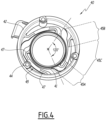
Fig. 4 is a view of a possible embodiment of a second centring element used in the electromechanical transducer offig. 1 - It should be noted that, in the following detailed description, components that are identical or similar from a structural and/or functional standpoint may have the same or different reference numbers, independently of whether they are shown in different embodiments of the present invention or in different parts.
- It should further be noted that, in order to provide a clear and concise description of this invention, the drawings may not necessarily be to scale, and some characteristics of the description may be shown schematically.
- Moreover, when the term "adapted" or "arranged" or "configured" or "shaped", or "set", or any similar term is used herein while referring to any component as a whole, or to any part of a component, or to a combination of components, it has to be understood that it means and encompasses correspondingly either the structure, and/or configuration and/or form and/or positioning.
- In addition, when the term "about" or "substantial" or "substantially" is used herein, it has to be understood as encompassing an actual variation of plus or
minus 5% with respect to what indicated as a reference value, position or axis, and when the terms transversal or transversally are hereby used, they have to be understood as encompassing a direction non-parallel to the reference part(s) or direction(s)/axis they refer to, and perpendicularity has to be considered a specific case of transverse direction. -
Figures 1 and2 show an electromechanical transducer according to the invention, indicated as a whole by thereference number 100, and in the following indicated also as 'shaker', shown in an exploded view of the components and with the assembled components shown in cross-section, respectively. - As a whole, the electromechanical transducer or
shaker 100 comprises a housing that is formed by assembling a plurality of components, i.e. two or more, some of which, as will be discussed in greater detail hereinafter, are configured to carry out other functions in addition to that of being components of the housing. - Amongst these components, the housing of the
shaker 100 according to the invention comprises at least one base 1, e.g. in the form of a substantially rigid plate, which is suitable to be solidly connected to a mounting wall by means of attachment means, e.g. ascrew 2. - The mounting wall, represented schematically in
figure 2 byreference number 102, is intended to be put under vibrations by theshaker 100, and is part of any device with which theshaker 100 is coupled; this device may be, by way of example and without limitation, a panel, a tailgate of an automobile to be vibrated in order to transmit sounds within the passenger compartment, part of a seat, or an element connected to a seat in an automobile, etc. - The housing contains a plurality of components, in particular a magnetodynamic assembly comprising a
coil 10, the windings of which (not shown in the drawings for clarity of illustration) are suitable to be supplied with electricity, and a magnetic circuit, indicated infigure 1 by theoverall reference number 20, which is operatively associated with thecoil 10, which circuit is arranged within the housing of thetransducer 100 so as to move axially along a reference axis X (in both directions) by virtue of the electromagnetic forces generated by supplying thecoil 10 with power. - In particular, as shown in
figure 1 , thecoil 10 comprises for example a firstcylindrical portion 12 around which the aforementioned windings are wound, and a secondcylindrical portion 14 that is concentric with and extends downward from the firstcylindrical portion 12. - In its turn, the mobile
magnetic circuit 20 comprises a lowerpolar element 21, for example disc-shaped, an upperpolar element 24, for example cup-shaped, and amagnet 22 positioned between the upper 24 and lower 21 polar elements. - In particular, the upper
polar element 24 comprises, on its upper surface, a firstupper wall 25, which is positioned in a substantially central position, and a secondupper wall 26, which extends along the peripheral edge of the upper surface itself. - Advantageously, the upper
polar element 24 further comprises a groove orrecessed area 27 which is provided between the central part where there is defined the firstupper wall 25 and the peripheral part where there is defined the secondupper wall 26. - The
electromechanical transducer 100 according to the invention further comprises at least: - a
first centring element 30, shown in detail infig. 3 , which is suitable to be connected to themagnetic circuit 20, and in particular to be fixed onto the firstupper wall 25 of the upperpolar element 24; - a
second centring element 40, shown in detail infig. 4 , suitable to be connected to themagnetic circuit 20, and, in particular, to a lower surface of the upperpolar element 24 itself, as shown infig. 2 ; - attachment means, advantageously comprising a
single mounting screw 50 or equivalent element, and an elasticallydeformable element 52 having a body with a slight contour in the shape of a dome, such as a cupola, or cup, or cone, which are suitable to allow fixing thefirst centring element 30 to the firstupper wall 25 of the upperpolar element 24 as described in greater detail in the following. - This elastically deformable element consists for example of a cup spring.
- In the embodiment shown, the
transducer 100 comprises ahousing 3, which is also substantially cylindrical, the body of which is arranged about an axis that, when the transducer is assembled, coincides with the reference axis X, and is configured so as to have at least oneshaped portion 4 suitable for housing a connector (not shown) to connecting to the power supply of the windings of thecoil 10, and aperipheral ring 5, the walls of which contribute to forming the housing of thetransducer 100 itself. Additionally, at theperipheral ring 5, in particular inside it, there are provided throughseats 5A, for example three. - The
transducer 100 further comprises: - an
upper cover 6; - a plurality of mounting screws or fastening tie rods 7, for example three in the embodiment shown, which are suitable to be inserted into holes 8 provided in the
cover 6 and arranged peripherally along the longitudinal development of thetransducer 100, and to be screwed into threadedseats 9 provided in the base 1 so as to assembly and connect them as a whole. - Usefully, in the
transducer 100 according to the invention, as shown in greater detail infigure 3 , thefirst centring element 30, which may be considered functionally as a spring, comprises a one-piece shaped body that is circular as a whole and extends on a transverse plane, and in particular substantially perpendicular, to the reference axis X, and has at least oneperipheral portion 32 suitable to be rigidly connected to the housing of thetransducer 100, at least onecentral portion 34 suitable to be rigidly fixed to the firstupper wall 25 of the upperpolar element 24, and at least one elastically deformableintermediate portion 36 that is arranged between and mechanically interconnects to each other the peripheral 32 and central 34 portions. - In particular, the
central portion 34 is substantially circular in shape relative to the reference axis X, and, at its centre, comprises a through hole 35 suited to allow the passage of themounting screw 50. - In its turn, the at least one
peripheral portion 32 comprises three circular sections that are substantially identical to one another and indicated by thesame reference number 32; between each pair of adjacentperipheral sections 32, aninlet 31 is provided, through which a corresponding mounting screw or rod 7 passes. - Advantageously, the at least one elastically deformable
intermediate portion 36 comprises three arms that are substantially identical to one another and are indicated by thesame reference number 36. - In particular, each
arm 36 has a curvilinear course and comprises an initialcurvilinear portion 36A that extends from an outer edge of thecentral portion 34, a finalcurvilinear portion 36B that joins with two adjacentperipheral sections 32 in the area in which therespective inlet 31 is provided between them, and acentral portion 36C, also curvilinear, which joints the respective initial andfinal portions - In particular, as shown in
figure 3 , and illustrated for the sake of simplicity solely for a pair ofarms 36, the threearms 36 are arranged equidistantly to one another at an angle of approximately 120°, for example by considering for each of them the conjunction between the respective midpoint of the respectiveinitial portion 36A with the central of the through hole 35. - Advantageously, at least one of the initial 36A and
final portions 36B, preferably both of them, has an average curvature radius R1 and R3, respectively, that is less than the average curvature radius R2 of thecentral portion 36C. - As shown in
figure 3 , the average curvature radius R3 is measured in correspondence of the edge of thefinal portion 36B which faces the respective adjacentperipheral section 32, whilst the average curvature radii R1 and R2 are measured, for instance relative to the curvilinear inner edge of the respective arm, namely the edge that faces thecentral portion 34, or they may all be measured by reference to the midlines of each portion. - In particular, the ratio between the diameter of the first centring element 30 (i.e. twice the distance between the centre of the
first centring element 30 itself and the outer edge of any of the outer peripheral sections 32) and the average curvature radius R3 of thefinal portion 36B is advantageously between 10 and 20. - Moreover, on the plane of the
first centring element 30, the average width, L1 and respectively L2, of both the initial 36A andfinal portions 36B is greater than the average width L3 of thecentral portion 36C. - Preferably, the
first centring element 30 is made of a metallic material. - In its turn, as shown in
figures 1 and4 , the second centring element comprises a one-piece shaped body which includes aninner portion 41, e.g. in the shape of a circular inner ring which extends about an axis that, when assembled, coincides substantially with the reference axis X; thiscircular ring 41 has a substantially L-shaped cross-section, as can be seen infig. 2 , which constitutes a support area for the lower portion of the upperpolar element 24. - Moreover, the second
centring element 40 includes anouter portion 42, e.g. substantially cylindrical in shape, extending around the same axis as the innercircular ring 41, and whose walls have a cross-section forming astep 43 abutting the upper part of thehousing 3. - The upper part of the walls of the
outer portion 42 contributes to the formation of the housing of thetransducer 100 itself, whilst the lower part is inserted into thehousing 3. - Along the walls of the
outer portion 42, there are provided throughholes 44, inside which the through screws/passing tie rods 7 are inserted. - Advantageously, the body of the
second centring element 40 also comprises an elastically deformableintermediate portion 45 that interconnects theinner portion 41 with theouter portion 43. - Advantageously, the at least one elastically deformable
intermediate portion 45 comprises three arms that are substantially identical to one another and are indicated by thesame reference number 45. - In particular, as shown in greater detail in
figure 4 only for a single arm for clarity's sake, eacharm 45 has a curvilinear course and comprises a curvilinearinitial portion 45A that extends from an outer edge of thecentral portion 41, a curvilinearfinal portion 45B that joins with the wall of theouter portion 42, and a central portion 34C, which is also curvilinear, and joins the respective initial andfinal portions - Conveniently, the three
arms 45 are arranged at a distance of approximately 120° from one another, for example by considering for each of them the conjunction of the midpoint of the respectiveinitial portion 45A with the centre of thering 41, as shown schematically infigure 4 . - In particular, the
initial portion 45A and thefinal portion 45B of eacharm 45 comprise a part, indicated by thesame reference number 47, with a thickness measured in the direction of the reference axis X that is greater than that of the central portion 44C. - Preferably, the
second centring element 40 is made of a plastic material. - During assembly, as shown for instance in
fig. 2 , thecoil 10 is arranged with its axis (coinciding with the axis of its coaxialcylindrical portions 12 and 14) substantially aligned with the reference axis X, and is fixed at the bottom to the base 1, in particular by gluing the inner surface of the secondcylindrical portion 14 to the base 1; moreover, the outer surface of the secondcylindrical portion 14 is fixed, in particular glued, to thehousing 3, which is resting on and glued to the base 1 with the walls of theperipheral ring 5 contributing in the formation of the housing of thetransducer 100 itself. - The lower
polar element 21, for example disk-shaped, is housed, together with at least one portion of themagnet 22, within the cylindrical body of thecoil 10, whilst the upperpolar element 24 is arranged outside the cylindrical body of thecoil 10. - In particular, in the embodiment shown, the cup-shaped body of the
polar element 24 is seated around thecoil 10, with its cavity facing downward, so as to form the necessary air gap. - The
second centring element 40 is arranged with its axis substantially coinciding with the reference axis X, and is coupled with the lower surface of the secondpolar element 24, e.g. by gluing its annularinner portion 41 around the lower portion of theupper magnet 24 itself. - In this position, the
step 43 of theouter portion 42 abuts the upper portion of thehousing 3, and the upper portion of the walls of theouter portion 42 itself contribute to the formation of the housing of thetransducer 100 itself, whilst the lower part is inserted within the walls of theperipheral ring 5. - Advantageously, the
first centring element 30 is fixed to the firstupper wall 25 of the upperpolar element 24 by means of the mountingscrew 50, with the elasticallydeformable element 52 arranged between thescrew 50 itself and the surface of the firstupper wall 25. - In practice, when fixing the
screw 50 to the upperpolar element 24, the elasticallydeformable body 52, which is positioned with its concave side facing thecentral portion 34 of thefirst centring element 30, deforms, and tends to flatten against it. - In this manner, at least one circular
peripheral portion 53 of theelement 52 tightly abuts and presses on a corresponding peripheral circular surface of thecentral portion 34; in its turn, this peripheral circular surface of thecentral portion 34 rests on and is pressed against the surface of the secondupper wall 26. - Thus, in the
transducer 100 according to the invention, thefirst centring element 30 is fixed to themagnetic circuit 20, and in particular to the upperpolar element 24, by means of a single mountingscrew 50 that is positioned along the reference axis X, with thedeformable element 52, and, in particular, its circular outerperipheral edge 53 substantially uniformly distributing the fixing pressure along its surface and, from there, to the corresponding peripheral circular surface of thecentral portion 34 on which it is pressing. The contact and the substantially uniform distribution of the pressure exerted by the circularperipheral portion 53 onto the corresponding circular peripheral portion of thecentral portion 34, which is discharged from this against the surface of the secondupper wall 26, are usefully favoured and rendered more effective thanks to the presence of the groove or recessedarea 27 which extends between the inner part of thecentral portion 34, i.e. that positioned around the through hole 35 which rests on the surface of the firstupper wall 25, and the peripheral circular surface of thecentral portion 34 which rests on and is pressed against the surface of the secondupper wall 27. - The
peripheral portion 32 of thefirst centring element 30 is inserted between the upper portion of theouter portion 42 and thecover 6, and firmly held therein; if needed, it is also possible to use an adhesive layer to bond the parts held between them. - The screws or fixing tie rods 7 are thus inserted into the holes 8 of the
cover 6, pass through theinlets 31, the throughhole seats second centring element 40 and thehousing 3, and are then screwed into theseats 9 provided in the base 1 so as to assemble and fix the various parts as a whole assembly. - In practice, it has been found that the
electromechanical transducer 100 according to the invention achieve the scope and tasks set since the connection between thecentring elements magnetic circuit 20 is realized, in a manner as a whole simpler than in the known solutions. In particular, thefirst centring element 30 is fixed to the mobilemagnetic circuit 20 according to a solution that is simple form a construction point of view and allows for a better distribution of both the magnetic fields at work and the mechanical stresses, ensuring a greater reliability. - Moreover, the particular configuration of the
first centring element 30, which, as indicated, acts as a spring for all intents and purposes, provides an optimal elastic constant and adequately balances the need for mobility with resistance to mechanical stresses. - To this end, the configuration of the
second centring element 40 also allows for an adequate balance between these needs. - In addition, the specific choice of materials, i.e. the combination of a metallic material for the
first centring element 30 and a plastic material for thesecond centring element 40, allows for a good balance between the necessary damping of movement between moving parts and the necessary mechanical performance at the various operating temperatures, and allows to be produced economically. In particular, thefirst centring element 30 may advantageously be obtained from a simple flat metal sheet, according to a solution simple and cheap. - Of course, without prejudice to the principle of the invention, the embodiments and specific implementations may be widely varied from the purely exemplary descriptions and illustrations herein, which are preferred, but do not constitute limitations, without departing from the scope of this invention as defined in particular in the claims appended hereto. For example, some of the components above described and/or one or more of their parts may be configured differently with respect to the configurations described herein, as long as they remain compatible with the purposes and functions provided by this invention; the number of fixing screws or tie rods 7 and the respective through hole seats and points of attachment may be different, or different attachment solutions may be used; the
magnetic circuit 20 may be made of a different number of parts, e.g. with one or more of thecomponents magnetic circuit 20 may be shaped and/or positioned differently to the shapes and/or positions described in the exemplary embodiment. For example, themagnetic circuit 20 may comprise a ring magnet arranged around the body of the coil, the upperpolar element 24 may be made using a T-shaped magnetic yoke, and the lowerpolar element 21 may consist of a polar plate arranged beneath the coil. The housing may be made of a different number of parts and/or configured differently, e.g. with its lateral surfaces not necessarily completely closed, etc.
Claims (10)
- Electromechanical transducer (100) suitable for generating vibrations to be transmitted to an external mounting wall (102), comprising:- a housing which includes a base (1) suitable to be solidly connected to said external mounting wall (102); and, arranged inside said housing at least:- a coil (10) which is fixed to at least said base (1) and devised to be electrically powered;- a magnetic circuit (20) which is movable along a virtual reference axis (X) and comprises at least a lower polar element (21), an upper polar element (24), and a magnet (22) interposed between said lower and upper polar elements (21, 24);- at least a first centering element (30) comprising at least a peripheral portion (32) constrained to said housing, a central portion (34), and at least an elastically deformable intermediate portion (36) which is arranged between and interconnects said peripheral and central portions (32, 34);- a fastening means (50) which is arranged along said reference axis (X) and is fixed to the upper polar element (24) thereby fixing solidly said central portion (34) to an upper surface of a first upper wall (25) of the upper polar element (24); and- an elastically deformable element (52) having a dome-shaped body which is positioned between said central portion (34) and said fastening means (50) with its own concavity facing towards said central portion (34), and wherein, following the fixing of said central portion (34) to the surface of the first upper wall (25) by means of said fastening means (50), the elastically deformable element (52) deforms at least partially with at least one peripheral circular (53) portion thereof which rests on pressing against a corresponding circular surface of the central portion (34), characterised in that:
said upper polar element (24) comprises a cup-shaped body which includes, at a substantially central portion, said first upper wall (25), a second upper wall (26), which extends along the peripheral edge of the cup-shaped body, and a recessed area (27) which is provided between the first upper wall (25) and the second upper wall (26), and wherein, following the fixing of said central portion (34) to the upper surface of the first upper wall (25) by means of said fastening means (50), said at least one peripheral circular (53) portion rests on pressing against a corresponding circular surface of the central portion (34) which in turn rests on and is pressed against an upper surface of said second upper wall (26). - Electromechanical transducer (100) according to claim 1, wherein said elastically deformable element (52) comprises a cup spring.
- Electromechanical transducer (100) according to one or more of the previous claims, wherein said elastically deformable intermediate portion (36) comprises three arms (36) substantially identical to each other which protrude from the central portion (34) substantially equidistant from each other.
- Electromechanical transducer (100) according to claim 3, wherein each arm (36) has a curvilinear course and comprises an initial curvilinear portion (36A) which extends from an outer edge of the central portion (34), a final curvilinear portion (36B) which is joined to the peripheral portion (32), and a central curvilinear portion (36C) which joins together said initial and final curvilinear portions (36A, 36B).
- Electromechanical transducer (100) according to claim 4, wherein at least one of said initial and final curvilinear portions (36A, 36B) has an average radius of curvature (R1, R3) smaller than the average radius of curvature (R2) of the portion central curvilinear (36C).
- Electromechanical transducer (100) according to one or more of claims 4 and 5, wherein at least one of said initial and final curvilinear portions (36A, 36B) has an average width (L1, L2) greater than the average width (L3) of the central curvilinear portion (36C).
- Electromechanical transducer (100) according to one or more of the preceding claims, wherein said first centering element (30) is realized in a single body made of metallic material.
- Electromechanical transducer (100) according to one or more of the preceding claims, further comprising a second centering element (40), connected at least to a lower surface of said upper polar element (24), said second centering element (40) comprising an inner portion (41) shaped as a circular ring, an outer portion (42) of a substantially cylindrical shape whose upper part forms part of the housing, and at least one elastically deformable intermediate portion (45) which interconnects the inner portion (41) with the outer portion (42) and comprises three arms (45) with a curvilinear course substantially identical to each other.
- Electromechanical transducer (100) according to claim 8, wherein each of said three arms (45) of the second centering element (40) comprises an initial curvilinear portion (45A) which extends from an outer edge of the central portion (41), a final curvilinear portion (45B) which is joined to the wall of the outer portion (42), and a central curvilinear portion (34C) which joins together the respective initial and final portions (45A, 45B).
- Electromechanical transducer (100) according to one or more of claims 8 and 9, wherein said second centering element (40) is realized in a single piece of plastic material.
Applications Claiming Priority (1)
| Application Number | Priority Date | Filing Date | Title |
|---|---|---|---|
| IT102021000013826A IT202100013826A1 (en) | 2021-05-27 | 2021-05-27 | Electromechanical transducer for the generation of vibrations to be transmitted to an external mounting wall |
Publications (2)
| Publication Number | Publication Date |
|---|---|
| EP4094849A1 EP4094849A1 (en) | 2022-11-30 |
| EP4094849B1 true EP4094849B1 (en) | 2025-03-19 |
Family
ID=77627218
Family Applications (1)
| Application Number | Title | Priority Date | Filing Date |
|---|---|---|---|
| EP22175305.6A Active EP4094849B1 (en) | 2021-05-27 | 2022-05-25 | Electromechanical transducer for generating vibrations to be transmitted to an external mounting wall |
Country Status (3)
| Country | Link |
|---|---|
| EP (1) | EP4094849B1 (en) |
| CN (1) | CN115412821A (en) |
| IT (1) | IT202100013826A1 (en) |
Family Cites Families (9)
| Publication number | Priority date | Publication date | Assignee | Title |
|---|---|---|---|---|
| KR200160178Y1 (en) * | 1997-08-05 | 1999-11-01 | 이종배 | Alarm and vibrator device |
| US6385327B1 (en) * | 1998-06-16 | 2002-05-07 | U.S. Philips Corporation | Device having two coaxially disposed bodies which are movable relative to one another along a translation axis |
| IT1395441B1 (en) * | 2009-09-09 | 2012-09-21 | Ask Ind Societa Per Azioni | MAGNETO-DYNAMIC TRANSDUCER WITH CENTRAL SYSTEM |
| KR101113561B1 (en) * | 2010-02-08 | 2012-02-24 | 삼성전기주식회사 | A vertical vibrator |
| US9282409B2 (en) * | 2014-04-09 | 2016-03-08 | Audio Design Experts, Inc. | Bass shaker transducer |
| KR101768531B1 (en) | 2015-12-23 | 2017-08-30 | 대동모벨시스템 주식회사 | Low sound generator for vehicles and its installation structure |
| US10462560B2 (en) * | 2018-01-08 | 2019-10-29 | Skullcandy, Inc. | Driver assemblies, headphones including driver assemblies, and related methods |
| JP6750825B2 (en) * | 2018-08-28 | 2020-09-02 | ミネベアミツミ株式会社 | Vibration actuator and electronic equipment |
| JP7313159B2 (en) * | 2019-02-27 | 2023-07-24 | フォスター電機株式会社 | vibration actuator |
-
2021
- 2021-05-27 IT IT102021000013826A patent/IT202100013826A1/en unknown
-
2022
- 2022-05-25 EP EP22175305.6A patent/EP4094849B1/en active Active
- 2022-05-27 CN CN202210591977.XA patent/CN115412821A/en active Pending
Also Published As
| Publication number | Publication date |
|---|---|
| CN115412821A (en) | 2022-11-29 |
| EP4094849A1 (en) | 2022-11-30 |
| IT202100013826A1 (en) | 2022-11-27 |
Similar Documents
| Publication | Publication Date | Title |
|---|---|---|
| EP0956736B2 (en) | Electro-dynamic exciter | |
| CN1934901B (en) | Multifunction vibration actuator and portable terminal device | |
| US6608541B2 (en) | Electromagnetic actuator | |
| US10855156B2 (en) | Vibration actuator | |
| JP7022617B2 (en) | Vibration actuator | |
| CN209134639U (en) | A kind of acoustical generator | |
| KR100262893B1 (en) | Piezo-electric motor | |
| CN1338194A (en) | Vibration exciter for creating bending wave vibration | |
| US20110278959A1 (en) | Linear vibrator | |
| AU2006302791A1 (en) | Inertial voice type coil actuator systems | |
| EP4094849A1 (en) | Electromechanical transducer for generating vibrations to be transmitted to an external mounting wall | |
| US8179024B2 (en) | Piezoelectric transducer device | |
| KR100691150B1 (en) | Vibration actuator | |
| CN116829273A (en) | vibration actuator | |
| US11239730B2 (en) | Rotating device | |
| JP3162715B2 (en) | Car horn | |
| JP2001326992A (en) | Small electroacoustic transducer | |
| WO2023243413A1 (en) | Vibration actuator | |
| JPH10112897A (en) | Electric / mechanical vibration transducer | |
| JP7728555B2 (en) | Vibration system and speaker | |
| US12191748B2 (en) | Vibration motor | |
| US20240223109A1 (en) | Ultrasonic motor | |
| CN101385389A (en) | Linear array transducer and methods of manufacture | |
| JP2024147152A (en) | Actuator | |
| CN118574062A (en) | Vibration sounding device, vibration sounding module, assembly method of vibration sounding module and electronic terminal |
Legal Events
| Date | Code | Title | Description |
|---|---|---|---|
| PUAI | Public reference made under article 153(3) epc to a published international application that has entered the european phase |
Free format text: ORIGINAL CODE: 0009012 |
|
| STAA | Information on the status of an ep patent application or granted ep patent |
Free format text: STATUS: THE APPLICATION HAS BEEN PUBLISHED |
|
| AK | Designated contracting states |
Kind code of ref document: A1 Designated state(s): AL AT BE BG CH CY CZ DE DK EE ES FI FR GB GR HR HU IE IS IT LI LT LU LV MC MK MT NL NO PL PT RO RS SE SI SK SM TR |
|
| STAA | Information on the status of an ep patent application or granted ep patent |
Free format text: STATUS: REQUEST FOR EXAMINATION WAS MADE |
|
| 17P | Request for examination filed |
Effective date: 20230516 |
|
| RBV | Designated contracting states (corrected) |
Designated state(s): AL AT BE BG CH CY CZ DE DK EE ES FI FR GB GR HR HU IE IS IT LI LT LU LV MC MK MT NL NO PL PT RO RS SE SI SK SM TR |
|
| GRAP | Despatch of communication of intention to grant a patent |
Free format text: ORIGINAL CODE: EPIDOSNIGR1 |
|
| STAA | Information on the status of an ep patent application or granted ep patent |
Free format text: STATUS: GRANT OF PATENT IS INTENDED |
|
| RIC1 | Information provided on ipc code assigned before grant |
Ipc: H04R 7/18 20060101ALN20241007BHEP Ipc: H04R 11/02 20060101ALI20241007BHEP Ipc: H04R 7/12 20060101ALI20241007BHEP Ipc: H02K 33/16 20060101ALI20241007BHEP Ipc: G10K 9/13 20060101ALI20241007BHEP Ipc: B06B 1/04 20060101AFI20241007BHEP |
|
| INTG | Intention to grant announced |
Effective date: 20241017 |
|
| RIN1 | Information on inventor provided before grant (corrected) |
Inventor name: GRAMACCIA, GASPARE Inventor name: VIOLI, FRANCESCO Inventor name: FALCIONI, ANDREA Inventor name: MASSINI, PIETRO |
|
| GRAS | Grant fee paid |
Free format text: ORIGINAL CODE: EPIDOSNIGR3 |
|
| GRAA | (expected) grant |
Free format text: ORIGINAL CODE: 0009210 |
|
| STAA | Information on the status of an ep patent application or granted ep patent |
Free format text: STATUS: THE PATENT HAS BEEN GRANTED |
|
| AK | Designated contracting states |
Kind code of ref document: B1 Designated state(s): AL AT BE BG CH CY CZ DE DK EE ES FI FR GB GR HR HU IE IS IT LI LT LU LV MC MK MT NL NO PL PT RO RS SE SI SK SM TR |
|
| REG | Reference to a national code |
Ref country code: GB Ref legal event code: FG4D |
|
| REG | Reference to a national code |
Ref country code: CH Ref legal event code: EP |
|
| REG | Reference to a national code |
Ref country code: IE Ref legal event code: FG4D |
|
| REG | Reference to a national code |
Ref country code: DE Ref legal event code: R096 Ref document number: 602022011866 Country of ref document: DE |
|
| P01 | Opt-out of the competence of the unified patent court (upc) registered |
Free format text: CASE NUMBER: APP_12818/2025 Effective date: 20250314 |
|
| PG25 | Lapsed in a contracting state [announced via postgrant information from national office to epo] |
Ref country code: RS Free format text: LAPSE BECAUSE OF FAILURE TO SUBMIT A TRANSLATION OF THE DESCRIPTION OR TO PAY THE FEE WITHIN THE PRESCRIBED TIME-LIMIT Effective date: 20250619 |
|
| PG25 | Lapsed in a contracting state [announced via postgrant information from national office to epo] |
Ref country code: FI Free format text: LAPSE BECAUSE OF FAILURE TO SUBMIT A TRANSLATION OF THE DESCRIPTION OR TO PAY THE FEE WITHIN THE PRESCRIBED TIME-LIMIT Effective date: 20250319 |
|
| PGFP | Annual fee paid to national office [announced via postgrant information from national office to epo] |
Ref country code: DE Payment date: 20250529 Year of fee payment: 4 |
|
| REG | Reference to a national code |
Ref country code: LT Ref legal event code: MG9D |
|
| PG25 | Lapsed in a contracting state [announced via postgrant information from national office to epo] |
Ref country code: NO Free format text: LAPSE BECAUSE OF FAILURE TO SUBMIT A TRANSLATION OF THE DESCRIPTION OR TO PAY THE FEE WITHIN THE PRESCRIBED TIME-LIMIT Effective date: 20250619 |
|
| PG25 | Lapsed in a contracting state [announced via postgrant information from national office to epo] |
Ref country code: HR Free format text: LAPSE BECAUSE OF FAILURE TO SUBMIT A TRANSLATION OF THE DESCRIPTION OR TO PAY THE FEE WITHIN THE PRESCRIBED TIME-LIMIT Effective date: 20250319 |
|
| PG25 | Lapsed in a contracting state [announced via postgrant information from national office to epo] |
Ref country code: LV Free format text: LAPSE BECAUSE OF FAILURE TO SUBMIT A TRANSLATION OF THE DESCRIPTION OR TO PAY THE FEE WITHIN THE PRESCRIBED TIME-LIMIT Effective date: 20250319 |
|
| PGFP | Annual fee paid to national office [announced via postgrant information from national office to epo] |
Ref country code: FR Payment date: 20250526 Year of fee payment: 4 |
|
| PG25 | Lapsed in a contracting state [announced via postgrant information from national office to epo] |
Ref country code: GR Free format text: LAPSE BECAUSE OF FAILURE TO SUBMIT A TRANSLATION OF THE DESCRIPTION OR TO PAY THE FEE WITHIN THE PRESCRIBED TIME-LIMIT Effective date: 20250620 Ref country code: BG Free format text: LAPSE BECAUSE OF FAILURE TO SUBMIT A TRANSLATION OF THE DESCRIPTION OR TO PAY THE FEE WITHIN THE PRESCRIBED TIME-LIMIT Effective date: 20250319 |
|
| REG | Reference to a national code |
Ref country code: NL Ref legal event code: MP Effective date: 20250319 |
|
| REG | Reference to a national code |
Ref country code: AT Ref legal event code: MK05 Ref document number: 1776550 Country of ref document: AT Kind code of ref document: T Effective date: 20250319 |
|
| PG25 | Lapsed in a contracting state [announced via postgrant information from national office to epo] |
Ref country code: NL Free format text: LAPSE BECAUSE OF FAILURE TO SUBMIT A TRANSLATION OF THE DESCRIPTION OR TO PAY THE FEE WITHIN THE PRESCRIBED TIME-LIMIT Effective date: 20250319 |
|
| PG25 | Lapsed in a contracting state [announced via postgrant information from national office to epo] |
Ref country code: SE Free format text: LAPSE BECAUSE OF FAILURE TO SUBMIT A TRANSLATION OF THE DESCRIPTION OR TO PAY THE FEE WITHIN THE PRESCRIBED TIME-LIMIT Effective date: 20250319 |
|
| PG25 | Lapsed in a contracting state [announced via postgrant information from national office to epo] |
Ref country code: SM Free format text: LAPSE BECAUSE OF FAILURE TO SUBMIT A TRANSLATION OF THE DESCRIPTION OR TO PAY THE FEE WITHIN THE PRESCRIBED TIME-LIMIT Effective date: 20250319 |
|
| PG25 | Lapsed in a contracting state [announced via postgrant information from national office to epo] |
Ref country code: ES Free format text: LAPSE BECAUSE OF FAILURE TO SUBMIT A TRANSLATION OF THE DESCRIPTION OR TO PAY THE FEE WITHIN THE PRESCRIBED TIME-LIMIT Effective date: 20250319 Ref country code: PT Free format text: LAPSE BECAUSE OF FAILURE TO SUBMIT A TRANSLATION OF THE DESCRIPTION OR TO PAY THE FEE WITHIN THE PRESCRIBED TIME-LIMIT Effective date: 20250721 |
|
| PG25 | Lapsed in a contracting state [announced via postgrant information from national office to epo] |
Ref country code: PL Free format text: LAPSE BECAUSE OF FAILURE TO SUBMIT A TRANSLATION OF THE DESCRIPTION OR TO PAY THE FEE WITHIN THE PRESCRIBED TIME-LIMIT Effective date: 20250319 |
|
| PGFP | Annual fee paid to national office [announced via postgrant information from national office to epo] |
Ref country code: IT Payment date: 20250531 Year of fee payment: 4 |
|
| RAP4 | Party data changed (patent owner data changed or rights of a patent transferred) |
Owner name: ASK INDUSTRIES S.P.A. |
|
| PG25 | Lapsed in a contracting state [announced via postgrant information from national office to epo] |
Ref country code: AT Free format text: LAPSE BECAUSE OF FAILURE TO SUBMIT A TRANSLATION OF THE DESCRIPTION OR TO PAY THE FEE WITHIN THE PRESCRIBED TIME-LIMIT Effective date: 20250319 |
|
| PG25 | Lapsed in a contracting state [announced via postgrant information from national office to epo] |
Ref country code: EE Free format text: LAPSE BECAUSE OF FAILURE TO SUBMIT A TRANSLATION OF THE DESCRIPTION OR TO PAY THE FEE WITHIN THE PRESCRIBED TIME-LIMIT Effective date: 20250319 Ref country code: CZ Free format text: LAPSE BECAUSE OF FAILURE TO SUBMIT A TRANSLATION OF THE DESCRIPTION OR TO PAY THE FEE WITHIN THE PRESCRIBED TIME-LIMIT Effective date: 20250319 |
|
| PG25 | Lapsed in a contracting state [announced via postgrant information from national office to epo] |
Ref country code: RO Free format text: LAPSE BECAUSE OF FAILURE TO SUBMIT A TRANSLATION OF THE DESCRIPTION OR TO PAY THE FEE WITHIN THE PRESCRIBED TIME-LIMIT Effective date: 20250319 |
|
| PG25 | Lapsed in a contracting state [announced via postgrant information from national office to epo] |
Ref country code: SK Free format text: LAPSE BECAUSE OF FAILURE TO SUBMIT A TRANSLATION OF THE DESCRIPTION OR TO PAY THE FEE WITHIN THE PRESCRIBED TIME-LIMIT Effective date: 20250319 |
|
| PG25 | Lapsed in a contracting state [announced via postgrant information from national office to epo] |
Ref country code: IS Free format text: LAPSE BECAUSE OF FAILURE TO SUBMIT A TRANSLATION OF THE DESCRIPTION OR TO PAY THE FEE WITHIN THE PRESCRIBED TIME-LIMIT Effective date: 20250719 |
|
| REG | Reference to a national code |
Ref country code: DE Ref legal event code: R097 Ref document number: 602022011866 Country of ref document: DE |
|
| REG | Reference to a national code |
Ref country code: CH Ref legal event code: H13 Free format text: ST27 STATUS EVENT CODE: U-0-0-H10-H13 (AS PROVIDED BY THE NATIONAL OFFICE) Effective date: 20251223 |
|
| PG25 | Lapsed in a contracting state [announced via postgrant information from national office to epo] |
Ref country code: DK Free format text: LAPSE BECAUSE OF FAILURE TO SUBMIT A TRANSLATION OF THE DESCRIPTION OR TO PAY THE FEE WITHIN THE PRESCRIBED TIME-LIMIT Effective date: 20250319 |
|
| PG25 | Lapsed in a contracting state [announced via postgrant information from national office to epo] |
Ref country code: LU Free format text: LAPSE BECAUSE OF NON-PAYMENT OF DUE FEES Effective date: 20250525 |
|
| PG25 | Lapsed in a contracting state [announced via postgrant information from national office to epo] |
Ref country code: CH Free format text: LAPSE BECAUSE OF NON-PAYMENT OF DUE FEES Effective date: 20250531 |
|
| PLBE | No opposition filed within time limit |
Free format text: ORIGINAL CODE: 0009261 |
|
| STAA | Information on the status of an ep patent application or granted ep patent |
Free format text: STATUS: NO OPPOSITION FILED WITHIN TIME LIMIT |
|
| REG | Reference to a national code |
Ref country code: CH Ref legal event code: L10 Free format text: ST27 STATUS EVENT CODE: U-0-0-L10-L00 (AS PROVIDED BY THE NATIONAL OFFICE) Effective date: 20260128 |
|
| REG | Reference to a national code |
Ref country code: BE Ref legal event code: MM Effective date: 20250531 |
|
| PG25 | Lapsed in a contracting state [announced via postgrant information from national office to epo] |
Ref country code: MC Free format text: LAPSE BECAUSE OF FAILURE TO SUBMIT A TRANSLATION OF THE DESCRIPTION OR TO PAY THE FEE WITHIN THE PRESCRIBED TIME-LIMIT Effective date: 20250319 |
|
| 26N | No opposition filed |
Effective date: 20251222 |
|
| PG25 | Lapsed in a contracting state [announced via postgrant information from national office to epo] |
Ref country code: IE Free format text: LAPSE BECAUSE OF NON-PAYMENT OF DUE FEES Effective date: 20250525 |
|
| PG25 | Lapsed in a contracting state [announced via postgrant information from national office to epo] |
Ref country code: BE Free format text: LAPSE BECAUSE OF NON-PAYMENT OF DUE FEES Effective date: 20250531 |