EP4094846A1 - Method for preventing ghosting in a slot coating die - Google Patents
Method for preventing ghosting in a slot coating die Download PDFInfo
- Publication number
- EP4094846A1 EP4094846A1 EP21305674.0A EP21305674A EP4094846A1 EP 4094846 A1 EP4094846 A1 EP 4094846A1 EP 21305674 A EP21305674 A EP 21305674A EP 4094846 A1 EP4094846 A1 EP 4094846A1
- Authority
- EP
- European Patent Office
- Prior art keywords
- horizontal channel
- die
- die part
- slot coating
- upstream
- Prior art date
- Legal status (The legal status is an assumption and is not a legal conclusion. Google has not performed a legal analysis and makes no representation as to the accuracy of the status listed.)
- Withdrawn
Links
- 238000000576 coating method Methods 0.000 title claims abstract description 125
- 239000011248 coating agent Substances 0.000 title claims abstract description 118
- 238000000034 method Methods 0.000 title claims abstract description 27
- 239000012530 fluid Substances 0.000 claims abstract description 119
- 238000011144 upstream manufacturing Methods 0.000 claims abstract description 88
- 239000000203 mixture Substances 0.000 claims abstract description 85
- 239000000758 substrate Substances 0.000 claims abstract description 50
- 238000007764 slot die coating Methods 0.000 claims abstract description 5
- 239000000463 material Substances 0.000 claims description 36
- 239000000945 filler Substances 0.000 claims description 23
- 239000000853 adhesive Substances 0.000 claims description 21
- 230000001070 adhesive effect Effects 0.000 claims description 21
- ATJFFYVFTNAWJD-UHFFFAOYSA-N Tin Chemical compound [Sn] ATJFFYVFTNAWJD-UHFFFAOYSA-N 0.000 claims description 4
- 230000000903 blocking effect Effects 0.000 claims description 4
- 229910010272 inorganic material Inorganic materials 0.000 claims description 4
- 239000011147 inorganic material Substances 0.000 claims description 4
- 229920001225 polyester resin Polymers 0.000 claims description 4
- 239000004645 polyester resin Substances 0.000 claims description 4
- 239000003822 epoxy resin Substances 0.000 claims description 3
- 229910052751 metal Inorganic materials 0.000 claims description 3
- 239000002184 metal Substances 0.000 claims description 3
- 239000011368 organic material Substances 0.000 claims description 3
- 150000002978 peroxides Chemical class 0.000 claims description 3
- 229920000647 polyepoxide Polymers 0.000 claims description 3
- 229920005749 polyurethane resin Polymers 0.000 claims description 3
- 238000004519 manufacturing process Methods 0.000 description 6
- -1 for example Substances 0.000 description 5
- 238000004891 communication Methods 0.000 description 3
- 239000010408 film Substances 0.000 description 3
- 238000012986 modification Methods 0.000 description 3
- 230000004048 modification Effects 0.000 description 3
- 239000010935 stainless steel Substances 0.000 description 3
- 229910001220 stainless steel Inorganic materials 0.000 description 3
- 229910052718 tin Inorganic materials 0.000 description 3
- PXHVJJICTQNCMI-UHFFFAOYSA-N Nickel Chemical compound [Ni] PXHVJJICTQNCMI-UHFFFAOYSA-N 0.000 description 2
- 239000004698 Polyethylene Substances 0.000 description 2
- 239000000123 paper Substances 0.000 description 2
- 229920000573 polyethylene Polymers 0.000 description 2
- RYGMFSIKBFXOCR-UHFFFAOYSA-N Copper Chemical compound [Cu] RYGMFSIKBFXOCR-UHFFFAOYSA-N 0.000 description 1
- 229920000742 Cotton Polymers 0.000 description 1
- 206010021639 Incontinence Diseases 0.000 description 1
- ZOKXTWBITQBERF-UHFFFAOYSA-N Molybdenum Chemical compound [Mo] ZOKXTWBITQBERF-UHFFFAOYSA-N 0.000 description 1
- 239000004952 Polyamide Substances 0.000 description 1
- 239000004743 Polypropylene Substances 0.000 description 1
- RTAQQCXQSZGOHL-UHFFFAOYSA-N Titanium Chemical compound [Ti] RTAQQCXQSZGOHL-UHFFFAOYSA-N 0.000 description 1
- 230000002745 absorbent Effects 0.000 description 1
- 239000002250 absorbent Substances 0.000 description 1
- 239000000956 alloy Substances 0.000 description 1
- 229910045601 alloy Inorganic materials 0.000 description 1
- 229910052782 aluminium Inorganic materials 0.000 description 1
- XAGFODPZIPBFFR-UHFFFAOYSA-N aluminium Chemical compound [Al] XAGFODPZIPBFFR-UHFFFAOYSA-N 0.000 description 1
- DQXBYHZEEUGOBF-UHFFFAOYSA-N but-3-enoic acid;ethene Chemical compound C=C.OC(=O)CC=C DQXBYHZEEUGOBF-UHFFFAOYSA-N 0.000 description 1
- 229920005549 butyl rubber Polymers 0.000 description 1
- 229920002678 cellulose Polymers 0.000 description 1
- 239000001913 cellulose Substances 0.000 description 1
- 239000000919 ceramic Substances 0.000 description 1
- 230000005465 channeling Effects 0.000 description 1
- 230000000052 comparative effect Effects 0.000 description 1
- 238000010924 continuous production Methods 0.000 description 1
- 239000010949 copper Substances 0.000 description 1
- 229910052802 copper Inorganic materials 0.000 description 1
- 238000005260 corrosion Methods 0.000 description 1
- 230000007797 corrosion Effects 0.000 description 1
- 230000002950 deficient Effects 0.000 description 1
- 230000001419 dependent effect Effects 0.000 description 1
- 229920001971 elastomer Polymers 0.000 description 1
- 239000005038 ethylene vinyl acetate Substances 0.000 description 1
- 239000004744 fabric Substances 0.000 description 1
- 239000000835 fiber Substances 0.000 description 1
- 239000011888 foil Substances 0.000 description 1
- 230000007246 mechanism Effects 0.000 description 1
- 229910052750 molybdenum Inorganic materials 0.000 description 1
- 239000011733 molybdenum Substances 0.000 description 1
- 229910052759 nickel Inorganic materials 0.000 description 1
- 150000001451 organic peroxides Chemical class 0.000 description 1
- 229920001200 poly(ethylene-vinyl acetate) Polymers 0.000 description 1
- 229920002647 polyamide Polymers 0.000 description 1
- 229920000139 polyethylene terephthalate Polymers 0.000 description 1
- 239000005020 polyethylene terephthalate Substances 0.000 description 1
- 229920000642 polymer Polymers 0.000 description 1
- 229920001155 polypropylene Polymers 0.000 description 1
- 239000004065 semiconductor Substances 0.000 description 1
- 229920006132 styrene block copolymer Polymers 0.000 description 1
- 239000010409 thin film Substances 0.000 description 1
- 239000011135 tin Substances 0.000 description 1
- 239000010936 titanium Substances 0.000 description 1
- 229910052719 titanium Inorganic materials 0.000 description 1
- WFKWXMTUELFFGS-UHFFFAOYSA-N tungsten Chemical compound [W] WFKWXMTUELFFGS-UHFFFAOYSA-N 0.000 description 1
- 229910052721 tungsten Inorganic materials 0.000 description 1
- 239000010937 tungsten Substances 0.000 description 1
Images


Classifications
-
- B—PERFORMING OPERATIONS; TRANSPORTING
- B05—SPRAYING OR ATOMISING IN GENERAL; APPLYING FLUENT MATERIALS TO SURFACES, IN GENERAL
- B05C—APPARATUS FOR APPLYING FLUENT MATERIALS TO SURFACES, IN GENERAL
- B05C5/00—Apparatus in which liquid or other fluent material is projected, poured or allowed to flow on to the surface of the work
- B05C5/02—Apparatus in which liquid or other fluent material is projected, poured or allowed to flow on to the surface of the work the liquid or other fluent material being discharged through an outlet orifice by pressure, e.g. from an outlet device in contact or almost in contact, with the work
- B05C5/0254—Coating heads with slot-shaped outlet
Definitions
- the present invention relates to a slot coating die for reducing or preventing ghosting of a fluid composition in particular an adhesive composition, during a slot coating die process.
- the present invention further relates to a method for applying the composition on the substrate by using said slot coating die.
- Coating processes can involve the application of a thin film of fluid material to a substrate, such as for example, paper, fabric, film, foil or sheet stock.
- a substrate such as for example, paper, fabric, film, foil or sheet stock.
- coatings are applied to improve the surface properties of the substrate, such as the substrate's appearance, adhesion, wettability, corrosion resistance, wear resistance and scratch resistance.
- coatings may also form an essential part of the finished product.
- a conventional slot coating die comprises an upstream die part and a downstream die part connected to the upstream die part such as to form a cavity therebetween. Pressurized fluid is introduced into the cavity and is then dispensed from the slot coating die onto the desired substrate.
- a conventional slot coating die may further comprise a patterned shim which makes it possible to control the width of the coating and obtain for example stripe patterns.
- a common problem in a slot coating process is the "ghosting issue” or "tailing issue".
- a composition such as an adhesive is applied on a substrate (for example a low-viscosity adhesive such as a wetness indicator adhesive) and when a quantity of adhesive is present at an area which should be devoid of adhesive.
- the adhesive applied on the substrate is not cut off and continues to flow or leak on an undesired area of the substrate.
- the ghosting issue is more commonly present in case of intermittent slot coating applications (for example when specific patterns should be formed on a substrate).
- the length of ghosting (in other words the length of the adhesive leakage on an undesired area of the substrate) is variable and depends on the structure of the slot coating die and the adhesive to be applied.
- the ghosting issue thus leads to defective, low-quality products or even failure of the manufacture process.
- At least part of the horizontal channel is filled with a filler material, preferably an organic material, an inorganic material or a metal, chosen from an epoxy resin, a polyurethane resin, a polyester resin, a metasilicate, tin, a peroxide and their mixtures.
- a filler material preferably an organic material, an inorganic material or a metal, chosen from an epoxy resin, a polyurethane resin, a polyester resin, a metasilicate, tin, a peroxide and their mixtures.
- the slot coating die comprises a blank shim plate located between the upstream die part and the downstream die part, the blank shim plate being configured to block the horizontal channel so as to prevent the fluid composition from flowing through the horizontal channel.
- the slot coating die comprises a restructured shim plate located between the upstream die part and the downstream die part, the restructured shim plate comprising an additional horizontal channel configured so that the fluid composition flows through said additional horizontal channel.
- the additional horizontal channel has a volume which is lower than the volume of the horizontal channel.
- the volume of the additional horizontal channel is from 50 to 25000 mm 3 , preferably from 50 to 1000 mm 3 , and preferably from 50 to 500 mm 3 .
- the additional horizontal channel is vertically offset relative to the horizontal channel, and is preferably located above the horizontal channel.
- the additional horizontal channel is at a distance from 2 mm to 50 mm, and preferably from 2 to 10 mm, from a lower edge of the restructured shim plate.
- the thickness of the restructured shim plate is from 0.1 to 1 mm; and preferably from 0.2 to 0.5 mm.
- the slot coating die further comprises a patterned shim plate between the upstream die part and the downstream die part, the patterned shim plate having a lower edge, wherein the lower edge comprises at least one cut-out.
- the invention further relates to a method for applying a fluid composition on a substrate by using the above slot coating die, the method comprising:
- the fluid composition is an adhesive material.
- the invention further relates to the use of the above slot coating die to reduce or prevent ghosting during a slot die coating process, wherein the slot die coating process comprises applying a fluid composition on a substrate by the slot coating die.
- the invention further relates to a method of restructuring an initial slot coating die for applying a fluid composition on a substrate, the initial slot coating die comprising:
- the method comprises a step of at least partly filling the horizontal channel with a filler material; and/or of adding a blank shim plate between the upstream die part and the downstream die part configured to block the horizontal channel so as to prevent the fluid composition from flowing through the horizontal channel; and/or of adding a restructured shim plate between the upstream die part and the downstream die part, the restructured shim plate comprising a an additional horizontal channel.
- the present invention enables to meet the abovementioned need.
- the invention provides a slot coating die and a coating method that make it possible to provide good quality products in an efficient and cost-effective manner without putting at risk the manufacture process.
- the slot coating die of the present invention is achieved by modifying an initial slot coating die comprising at least one horizontal channel on one of the upstream die part or the downstream die part, so as to at least partly block said horizontal channel in order to prevent the fluid composition from flowing through at least part of the horizontal channel.
- the fluid composition may flow through only one part of the horizontal channel, which has thus a reduced effective length; and/or it may flow through a different, additional horizontal channel, provided on a plate placed between the upstream die part and the downstream die part.
- ghosting is advantageously reduced in the modified or restructured slot coating die relative to the initial slot coating die, without having to entirely manufacture a new slot coating die.
- this can be carried out either by filling at least part of the horizontal channel with a filler material or by blocking the horizontal channel with a blank shim plate and by forming an additional horizontal channel.
- the additional horizontal channel may have a smaller volume relative to the volume of the horizontal channel.
- the additional horizontal channel may be vertically offset relative to the horizontal channel.
- an initial slot coating die which is a conventional slot coating die
- a modified or restructured slot coating die which is a slot coating die according to the invention and can be obtained by modifying the initial slot coating die.
- Each slot coating die described herein is assumed to be oriented in the vertical direction, as shown in Figure 1 , the substrate to be coated being disposed under the slot coating die.
- the terms “lower”, “upper”, “vertical” and the like are used with reference to this configuration.
- die or “slot coating die” refer to a shaped body or block comprising one or more portions through which a fluid material is extruded or drawn.
- the initial slot coating die comprises an upstream die part 1 and a downstream die part 2.
- upstream and downstream refer to the direction of travel of the substrate relative to the slot coating die.
- the substrate travels from “upstream” to “downstream” relative to the slot coating die. To put it otherwise, the portion of the substrate situated upstream of the slot coating die has not been coated yet, whereas the portion of the substrate situated downstream of the slot coating die has already been coated.
- the upstream die part 1 has a first face 5 and a lower edge 6 (or coating edge).
- the downstream die part 2 has a second face 7 and a lower edge 8 (or coating edge).
- the first face 5 of the upstream die part 1 faces and is parallel to the second face 7 of the downstream die part 2. Both faces are vertically oriented.
- the upstream die part 1 and the downstream die part 2 are spaced apart, so as to form an internal space, in which plates may be inserted.
- the lower edge 6 of the upstream die part 1 is preferably aligned with the lower edge 8 of the downstream die part 2 (as can be seen on Figure 1 ).
- both lower edges 6, 8 are at the same vertical level; or both lower edges 6, 8 are in the same horizontal plane; or the lower edge 6 of the upstream die part 1 faces the lower edge 8 of the downstream die part 8.
- the upstream die part 1 may comprise one or more fixation holes 9 on the first face 5 of the upstream die part 1 (eight fixation holes 9 are illustrated in Figure 2 ). Generally, the number of fixation holes 9 is determined by the length of the upstream die part 1, the longer the upstream die part 1 is, the more fixation holes 9 are required.
- the downstream die part 2 may comprise at least one fixation hole 11 on the second face 7 of the downstream die part 2 (eight fixation holes 11 are illustrated in Figure 3 ).
- the number of fixation holes 11 is determined by the length of the downstream die part 2, the longer the downstream die part 2 is, the more fixation holes 11 are required.
- fixation holes 9, 11 have a round shape, in other words a circular shape.
- the diameter of the fixation holes 9, 11 may be from 0.5 to 20 mm and preferably from 2 to 15 mm.
- the number of fixation holes 9 in the upstream die part 1 be equal to the number of fixation holes 11 in the downstream die part 2, and that the respective fixation holes 9, 11 in the two parts 1, 2 be aligned.
- fixation elements are preferably inserted into the respective fixation holes 9, 11 so as to connect and firmly maintain together the upstream and downstream die parts 1, 2.
- Fixation elements may e.g. include pins and screws.
- the initial slot coating die comprises at least one fluid inlet 12 for introducing the fluid composition into the internal space between the upstream and downstream die parts 1, 2.
- the at least one fluid inlet 12 is present on the upstream die part 1 of the slot coating die (not illustrated in the figures).
- the at least one fluid inlet 12 is present on the downstream die part 2 of the slot coating die (as illustrated in Figure 3 ).
- the downstream die part 2 illustrated in Figure 3 comprises one fluid inlet 12, but the presence of more than one (for example two, three or four) fluid inlets 12 are also possible.
- the initial slot coating die comprises a horizontal channel 13 for channeling the fluid composition from the one or more fluid inlet(s) 12 to the outlet(s) of the slot coating die.
- the horizontal channel 13 is present on the first face 5 of the upstream die part 1 of the slot coating die (as illustrated in Figure 2 ).
- the horizontal channel 13 is present on the second face 7 of the downstream die part 2 of the slot coating die (not illustrated in the figures).
- the horizontal channel 13 comprises an elongated, horizontal, section, configured for distributing fluid composition to a certain length of the die.
- the horizontal channel 13 may comprise one or more sections 13a perpendicular to the elongated section, so as to channel the fluid composition to the elongated section.
- the horizontal channel 13 has an upper edge 13b and a lower edge 13c.
- the volume of the horizontal channel 13 may be from 100 to 100000 mm 3 , preferably from 100 to 20000 mm 3 and preferably from 100 to 5000 mm 3 .
- volume of the horizontal channel 13 is meant the volume of the elongated, horizontal, section and the volume of the one or more sections 13a perpendicular to the elongated section.
- the fluid inlet(s) 12 is(are) present on the die part (upstream or downstream) that comprises the horizontal channel 13.
- the fluid inlet(s) 12 is(are) continuous with the horizontal channel 13; or the fluid connection between the fluid inlet(s) 12 and the horizontal channel 13 may be provided owing to a connecting channel present on a plate pressed against the die part.
- the fluid inlet(s) 12 is(are) present on the die part (upstream or downstream) which is devoid of horizontal channel 13.
- the initial slot coating die may further comprise at least a patterned shim plate 18 between the upstream die part 1 and the downstream die part 2, as illustrated in Figures 8A and 8B .
- the patterned shim plate 18 may for example have a rectangular shape, comprise two faces (face E illustrated in the figures and face F not illustrated in the figures) and four edges. More particularly the patterned shim plate 18 may be defined by an upper edge 18a, a lower edge 18b, and two lateral edges 18c, 18d.
- the upper edge 18a and the lower edge 18b be longer than the two lateral edges 18c, 18d.
- the patterned shim plate 18 be elongated in a horizontal direction. The exact dimensions of the patterned shim plate 18 depend on the dimensions of the upstream die part 1 and of the downstream die part 2.
- the upper edge 18a and the lower edge 18b can have a length e.g. from 1 to 500 cm, preferably from 5 to 300 cm, and more preferably from 10 to 100 cm.
- the two lateral edges 18c, 18d can have a length e.g. from 1 to 80 cm, and more preferably from 2 to 50 cm.
- the patterned shim plate 18 according to the invention may have a thickness from 0.1 to 1 mm; and preferably from 0.1 to 0.5 mm and more preferably from 0.1 to 0.2 mm (for example approximately 0.15 mm).
- thickness is meant the distance between face E and face F of the patterned shim plate 18.
- the patterned shim plate 18 may also comprise at least one and preferably a plurality of fixation holes 19 through its entire thickness.
- the number, shape and positioning of the fixation holes 19 preferably correspond to number, shape and positioning of the fixation holes 9, 11 in the upstream and downstream die parts 1, 2.
- the patterned shim plate 18 may further comprise at least one fluid hole 20 through the entire thickness of the patterned shim plate 18.
- the number, size and positioning of the fluid holes 20 then preferably correspond to the number, size and positioning of the fluid inlets 12.
- the fluid composition may be fed by the fluid inlets 12, flow through the corresponding fluid holes 20 on the patterned shim plate 18, and then flow through the horizontal channel 13 when it is located on a different die part from the fluid inlets 12.
- the presence of the at least one fluid hole 20 on the patterned shim depends on the location of the horizontal channel 13 and the fluid inlets 12.
- the lower edge 18b of the patterned shim plate 18 comprises at least one cut-out 21, preferably at least two, or at least three, or at least five cut-outs 21.
- the patterned shim plate 18 may comprise from 1 to 3, or from 3 to 5; or from 5 to 7; or from 7 to 9; or from 9 to 11; or from 11 to 13; or from 13 to 15; or even more than 15 cut-outs 21.
- the patterned shim plate 18 illustrated in Figure 8A comprises a single cut-out 21 while the patterned shim plate 18 illustrated in Figure 8B comprises three cut-outs 21.
- the cut-outs 21 may for example be rectangular-shaped or square-shaped. However, as the number of cut-outs 21 varies depending on the pattern, it is possible that the number of cut-outs 21 is more than 10, or more than 50, or even more than 100.
- all cut-outs 21 when more than one cut-outs 21 are present on the patterned shim plate 18, all cut-outs have the same horizontal length (length in a direction parallel to the upper edge 18a and the lower edge 18b of the patterned shim plate 18).
- the length of the various cut-outs 21 may differ.
- each cut-out 21 may be for example from 1 mm to 250 cm; and preferably from 1 mm to 200 cm.
- the cut-outs 21 are in fluid communication with the horizontal channel in the initial slot coating die.
- the cut-outs 21 form the outlets of the slot coating die.
- the fluid composition flows from the fluid inlet(s) 20 to the horizontal channel 13, and then exits the slot coating die from the cut-outs 21.
- the different parts of the slot coating die can be secured together using various fastening mechanisms such as screws, bolts and pins.
- this initial slot coating die is modified so that the horizontal channel 13 is at least partially blocked.
- the fluid composition is prevented from flowing through at least part of the horizontal channel 13.
- only part of the horizontal channel 13 is blocked.
- the fluid composition may flow through the unblocked part of the horizontal channel 13 and then be dispensed through some or all of the cut-outs 21.
- the totality of the horizontal channel 13 may be blocked.
- an additional horizontal channel 17 is provided to dispense the fluid composition to some or all of the cut-outs 21.
- the modification of the slot coating die can be performed by:
- the patterned shim plate 18 can be replaced by another patterned shim plate 18.
- the slot coating die comprises the parts described above, namely the upstream and downstream die parts 1, 2 and preferably the patterned shim plate 18, and further comprises the following features described below.
- the horizontal channel 13 is configured so that the horizontal channel 13 is at least partially blocked.
- this is achieved by filling the horizontal channel 13 with a filler material.
- a filler material may be an organic material, an inorganic material or a metal.
- the filler material may be an inorganic material.
- the filler material may be chosen from an epoxy resin, a polyurethane resin, a polyester resin, a metasilicate, tin, a peroxide and their mixtures.
- the entire volume of the horizontal channel 13 is filled with the filler material.
- the effective volume of the horizontal channel 13 becomes zero (or approximately zero) and as a result, during the coating process the fluid to be applied does not flow through the horizontal channel 13.
- a restructured shim plate may be used to form an additional horizontal channel 17 different from the horizontal channel 13.
- only part of the horizontal channel 13 is filled with a filler material.
- the volume of the horizontal channel 13 is reduced relative to its initial volume.
- the horizontal channel 13 in case only part of the horizontal channel 13 is filled with a filler material, such part is at least one, and more preferably both of the extremities of the horizontal channel 13.
- one or both of the extremities of the horizontal channel 13 may be filled with a filler material while the central part of the horizontal channel 13 is devoid of filler material so that the fluid composition can flow through the non-filled part of the horizontal channel 13.
- the volume of the partially filled horizontal channel 13 may be from 50 to 25000 mm 3 , preferably from 50 to 1000 mm 3 , and preferably from 50 to 500 mm 3 .
- the volume of the partially filled horizontal channel 13 may depend on the viscosity of the fluid composition. For example, the higher the viscosity of the fluid composition, the bigger the volume of the horizontal channel 13.
- the horizontal channel 13 is blocked with a blank shim plate 3 devoid of a horizontal channel.
- the blank shim plate 3 is inserted between the upstream and downstream die parts 1, 2 and fully obstructs the horizontal channel 13.
- shim plate is meant a thin, substantially planar sheet of material.
- the blank shim plate 3 may have a substantially rectangular shape. It comprises two faces (face A illustrated in the figures and face B not illustrated in the figures) and may comprise four edges. More particularly the blank shim plate 3 may comprise an upper edge 3a, a lower edge 3b, and two lateral edges 3c, 3d. Each edge of the blank shim plate 3 may be devoid of cut-outs and protrusions, in other words each edge of the blank shim plate 3 may be straight (linear).
- the upper edge 3a and the lower edge 3b be longer than the two lateral edges 3c, 3d.
- the blank shim plate 3 be elongated in a horizontal direction.
- the exact dimensions of the blank shim plate 3 depend on the dimensions of the upstream die part 1 and of the downstream die part 2.
- the upper edge 3a and the lower edge 3b can have a length from 1 to 500 cm, preferably from 5 to 300 cm, and more preferably from 10 to 100 cm.
- the two lateral edges 3c, 3d can have a length from 1 to 80 cm, and more preferably from 2 to 50 cm.
- the blank shim plate 3 may have a thickness from 0.1 to 5 mm; preferably from 0.5 to 5 mm; and more preferably from 0.5 to 1.5 mm.
- thickness is meant the distance between the face A and the face B of the blank shim plate 3.
- the patterned shim plate 18 has the same thickness as the blank shim plate 3.
- the patterned shim plate 18 may have a different thickness from the thickness of the blank shim plate 3.
- the blank shim plate 3 be thicker than the patterned shim plate 18.
- the blank shim plate 3 can be thicker than the patterned shim plate 18 by 0.05 to 1 mm, preferably from 0.1 to 0.5 mm, and even more preferably from 0.1 to 0.25 mm.
- the blank shim plate 3 may further comprise at least one, preferably several fixation holes 14 through its entire thickness.
- the number, shape and positioning of the fixation holes 14 preferably correspond to number, shape and positioning of the fixation holes 9, 11 in the upstream and downstream die parts 1, 2.
- the slot coating die may further comprise a restructured shim plate 4 as illustrated in Figure 5 , located between the upstream die part and the downstream die part as illustrated in Figure 1 . More particularly, in case the horizontal channel 13 is (preferably completely) filled with a filler material, the restructured shim plate 4 is located so as to be in contact with the part (upstream or downstream) comprising the horizontal channel 13. Alternatively, in case the slot coating die comprises a blank shim plate 3, the blank shim plate 3 is located between the restructured shim plate 4 and the die part 1, 2 (upstream or downstream) comprising the horizontal channel 13.
- the restructured shim plate 4 may for example have a rectangular shape and comprises two faces (face C illustrated in the figures and face D not illustrated in the figures) and may comprise four edges. More particularly the restructured shim plate 4 may be defined by an upper edge 15a, a lower edge 15b, and two lateral edges 15c, 15d.
- the upper edge 15a and the lower edge 15b be longer than the two lateral edges 15c, 15d.
- the restructured shim plate 4 be elongated in a horizontal direction. It is even more preferable that the shape of the restructured shim plate 4 be substantially the same as the shape of the blank shim plate 3. Naturally, as for the blank shim plate 3, the exact dimensions of the restructured shim plate 4 depend on the dimensions of the upstream die part 1 and of the downstream die part 2.
- the upper edge 15a and the lower edge 15b can have a length e.g. from 1 to 500 cm, preferably from 5 to 300 cm, and more preferably from 10 to 100 cm.
- the two lateral edges 15c, 15d can have a length e.g. from 1 to 80 cm, and more preferably from 2 to 50 cm.
- the upper edge 15a of the restructured shim plate 4 has the same length as the upper edge 3a of the blank shim plate 3.
- the restructured shim plate 4 according to the invention may have a thickness from 0.1 to 1 mm; and preferably from 0.2 to 0.5 mm.
- thickness is meant the distance between face C and face D of the restructured shim plate 4.
- the thickness of the restructured shim plate 4 is greater than the thickness of the patterned shim plate.
- the restructured shim plate 4 may also comprise at least one, preferably several fixation holes 16 through its entire thickness.
- the number, shape and positioning of the fixation holes 16 preferably correspond to number, shape and positioning of the fixation holes 9, 11 in the upstream and downstream die parts 1,2.
- the restructured shim plate 4 comprises a horizontally elongated opening which forms an additional horizontal channel 17.
- This additional horizontal channel 17 comprises an elongated, horizontal, section.
- it may comprise one or more sections 17a perpendicular to the elongated section, so as to channel the fluid composition from the fluid inlet(s) 12 to the elongated section.
- the number of sections 17a perpendicular to the elongated section on the restructured shim plate 4 is preferably the same as the number of fluid inlet(s) 12.
- the additional horizontal channel 17 has an upper edge 17b and a lower edge 17c.
- this additional horizontal channel 17 is formed by a through hole in the restructured shim plate 4.
- the additional horizontal channel 17 is closed by two parts pressed on either side of the restructured shim plate 4, such as a die part 1, 2 (upstream or downstream) comprising the (filled) horizontal channel 13 and the patterned shim plate 18; or such as the blank shim plate 3 and the patterned shim plate 18.
- the additional horizontal channel 17 is formed as a depression in the restructured shim plate 4, which is not a through hole.
- the additional horizontal channel 17 is closed on one side by the restructured shim plate 4 itself, and on the other side by the die part 1, 2 (upstream or downstream) comprising the (filled) horizontal channel 13 or the blank shim plate 3 against which it is pressed.
- the additional horizontal channel 17 has a volume which is lower than the volume of the (unblocked) horizontal channel 13 (in the initial slot coating die).
- volume of the additional horizontal channel is meant the total volume of the elongated, horizontal, section and the volume of the one or more sections 17a perpendicular to the elongated section if present.
- volume of the (unblocked) horizontal channel 13 is meant the total volume of the elongated, horizontal, section and the volume of the one or more sections 13a perpendicular to the elongated section if present.
- FIG. 6A Such embodiment is illustrated in Figures 6A and 6B .
- a restructured shim 4 is superposed on a die part (downstream or upstream) comprising a horizontal channel 13 (illustrated with a dotted line) entirely filled with a filler material 18.
- a restructured shim 4 is superposed on a die part (downstream or upstream) comprising a horizontal channel 13 (illustrated with a dotted line) and a blank shim plate 3.
- the blank shim plate 3 is located between the die part (downstream or upstream) comprising a horizontal channel 13 and the restructured shim plate 4.
- the smaller volume of the additional horizontal channel 17 makes it possible to increase pressure during the application of the fluid composition while applying the same amount of the adhesive and also allows to retain a smaller amount of the adhesive when the slot coating die is not applying any fluid composition on the substrate (in other words, when the slot coating is not operating). As a result, the ghosting of the fluid composition on the substrate is reduced.
- the volume of the additional horizontal channel 17 may be from 50 to 25000 mm 3 , preferably from 50 to 1000 mm 3 , and preferably from 50 to 500 mm 3 . It goes without saying that the volume of this channel depends on the size of the slot coating die and the viscosity of the fluid composition to be applied.
- the volume of the additional horizontal channel 17 may be reduced relative to the volume of the horizontal channel 13 by from 5 to 95 %, preferably from 10 to 90 %.
- the distance between the lower edge 17c of the additional horizontal channel 17 and the lower edge 15b of the restructured shim plate 4 is different from, preferably higher than the distance between the lower edge 13c of the horizontal channel 13 and the lower edge 6 of the upstream die part 1 if the horizontal channel 13 is located on the upstream die part 1 (as illustrated in Figure 2 ), or the lower edge 8 of the downstream die part 2 if the horizontal channel 13 is located on the downstream die part 2 (not illustrated in figures).
- the additional horizontal channel 17 is vertically offset (preferably upwards) relative to the horizontal channel 13.
- FIG. 7A Such embodiment is illustrated in Figures 7A and 7B .
- a restructured shim 4 is superposed on a die part (downstream or upstream) comprising a horizontal channel 13 (illustrated with a dotted line) entirely filled with a filler material 18.
- the additional horizontal channel 17 is located above the horizontal channel 13 in the vertical direction.
- a restructured shim 4 is superposed on a die part (downstream or upstream) comprising a horizontal channel 13 (illustrated with a dotted line) and a blank shim plate 3.
- the blank shim plate 3 is located between the die part (downstream or upstream) comprising a horizontal channel 13 and the restructured shim plate 4.
- the additional horizontal channel 17 is located above the horizontal channel 13. This offset makes it possible to reduce ghosting of the fluid composition on the substrate.
- This vertical offset between the channels may be from 1 to 10 mm; and preferably from 1 to 5 mm.
- this difference may be from 1 to 2 mm; or from 2 to 3 mm; or from 3 to 4 mm; or from 4 to 5 mm; or from 5 to 6 mm; or from 6 to 7 mm; or from 7 to 8 mm; or from 8 to 9 mm; or from 9 to 10 mm.
- the distance of the lower edge 17c of the additional horizontal channel 17 and the lower edge 15b of the restructured shim plate 4 may be from 2 mm to 50 mm, and preferably from 2 to 10 mm.
- the distance between the lower edge 13c of the horizontal channel 13 and the lower edge 6 of the upstream die part 1 if the channel 13 is located on the upstream die part 1 (as illustrated in Figure 2 ) or the lower edge 8 of the downstream die part 2 if the channel 13 is located on the downstream die part 2 (not illustrated in figures) may be from 1 to 40 mm and preferably from 1 to 5 mm.
- the restructured shim plate 4 may have the features of both Figure 6A and Figure 7A .
- the additional horizontal channel 17 may have a volume which is lower than the volume of the horizontal channel 13 and it may be vertically offset relative to the horizontal channel 13.
- the restructured shim plate 4 may have the features of both Figure 6B and Figure 7B .
- the slot coating die of the invention comprises the following layered arrangement:
- the slot coating die of the invention comprises the following layered arrangement:
- the slot coating die of the invention comprises the following layered arrangement:
- the upstream die part 1 and the downstream die part 2 can for example be manufactured from stainless steel.
- Each of the blank shim plate 3, restructured shim plate 4 and patterned shim plate 18 can for example be manufactured from a material chosen from stainless steel, aluminum, ceramic, titanium, nickel, copper, tin, tungsten, molybdenum, alloys and/or combinations thereof. According to preferred embodiments, they are manufactured from stainless steel. According to preferred embodiments, these plates are manufactured from the same material.
- the fluid composition is fed to the additional horizontal channel 17 via the fluid inlet(s) 12 (if the horizontal channel 13 is fully blocked); or the fluid composition is fed to the unblocked ( e.g. unfilled) portion of the horizontal channel 13 (if it is not fully blocked); and the fluid composition is then dispensed through the outlet(s) of the slot coating die.
- the composition can be applied in the form of patterns, especially strips, depending on the shape, number and positioning of the outlet(s) formed by the one or more cut-outs 21.
- the fluid composition may be introduced into the fluid inlet(s) 12 using for example a metering pump configured to pump and transport the pressurized fluid composition through a hose and into the fluid inlet(s) 12.
- the fluid composition may have a temperature from 25 to 250°C.
- the fluid composition is preferably an adhesive material.
- the adhesive material may for example comprise a rubber-based polymer such as a styrene block copolymer, butyl rubber and ethylene vinyl acetate.
- the adhesive material is a wet-indicator adhesive material for a sanitary absorbent article, such as a diaper or an adult incontinence product.
- the substrate may be for example a film, or a woven or nonwoven material, which may for example be made of polypropylene, polyethylene, polyethylene terephthalate, polyamide, paper or any other cellulose-based material, natural fibers such as cotton fibers, and combinations thereof.
- the substrate may move from upstream to downstream.
- a lower part of the slot coating die may contact the substrate.
- the temperature of the fluid exiting the slot coating die and being applied onto the substrate can be from 30 to 350°C, and preferably from 100 to 200°C.
- the speed of the coating of the substrate may be from 5 to 800 m/min, and preferably from 100 to 500 m/min.
- the fluid applied on the substrate may have a thickness of 0.001 to 5 mm.
- the coating of a substrate with the slot coating die of the present invention may be a continuous process.
- the coating of a substrate with the slot coating die of the present invention may be a discontinuous (intermittent) process.
- the present invention makes it possible to reduce the ghosting of the fluid composition on the substrate. Therefore, the ghosting length may be from 0 to 60 mm, preferably from 0 to 20 mm, more preferably from 0 to 10 mm, even more preferably from 0 to 5 mm.
- ghosting length is meant the length of the fluid composition applied on the substrate adjacent an area of the substrate on which the fluid composition is sought to be applied.
- the present invention makes it possible to modify an existing slot coating die in order to reduce or suppress ghosting when it is observed.
- the ghosting phenomenon may occur for a fluid composition having a viscosity from 100 to 10000 cps, and preferably from 200 to 5000 cps.
- a wetness indicator adhesive was coated on the surface of a polyethylene film at a temperature of 90°C or 110°C and with a speed of 250 m/min.
- Coating of the substrate with the adhesive was achieved first by using a slot coating die comprising a blank shim plate and a restructured shim plate (Tests 1 to 7), then by using a slot coating die wherein the horizontal channel was filled with a filler material (mixture of organic peroxides and polyester resin) and comprising a restructured shim plate (Tests 8 to 12) and then by using a slot coating die devoid of filler material and devoid of blank shim plate and restructured shim plate (Tests 13 to 14 - comparative).
- a patterned shim plate having a thickness of 0.15 mm was used. When a restructured shim plate was used, different vertical offset values relative to the horizontal channel were tested.
- the adhesive was coated on the substrate at a quantity of 25 g of adhesive/m 2 , at a speed of 250 mpm.
- the coating of the substrate is a discontinuous (intermittent) process to form alternating 200 mm coated areas and 270 mm uncoated areas.
- Test Blank shim plate Filler material Vertical offset (mm) Restructured shim thickness (mm) Application temperature (°C) Length of ghosting (mm) 1 Yes No 4 0.2 90 10 2 Yes No 4 0.2 110 10 3 Yes No 1 0.2 90 40-50 4 Yes No 1 0.2 110 20-40 5 Yes No 4 0.5 90 20-50 6 Yes No 4 0.5 110 20-40 7 Yes No 1 0.5 90 30-60 8 No Yes 4 0.2 90 10-15 9 No Yes 4 0.2 110 10-15 10 No Yes 1 0.2 90 40-50 11 No Yes 1 0.2 110 25-35 12 No Yes 4 0.5 90 20-30 13 No No 1 - 90 No cut-off 14 No No 1 - 110 No cut-off
- the ghosting length is measured by measuring the length of the fluid composition applied on the substrate adjacent the area of the substrate on which the fluid composition was applied.
Landscapes
- Application Of Or Painting With Fluid Materials (AREA)
Abstract
The invention relates to a slot coating die for applying a fluid composition on a substrate, comprising: an upstream die part (1) having a first face (5); a downstream die part (2) having a second face (7), the first face (5) of the upstream die part (1) facing and being parallel to the second face (7) of the downstream die part (2); wherein at least one of the upstream die part (1) and the downstream die part (2) comprises at least one fluid inlet (12) configured for making the fluid composition flow between the upstream die part (1) and the downstream die part (2), and wherein at least one of the upstream die part (1) and the downstream die part (2) comprises at least one horizontal channel (13) on the first face (5) or second face (6), wherein the horizontal channel (13) is at least partially blocked so that the fluid composition is prevented from flowing through at least part of the horizontal channel (13).
The invention further relates to a method for applying a fluid composition on a substrate by using said slot coating die and the use of said slot coating die to reduce or prevent ghosting during a slot die coating process.
The invention further relates to a method of restructuring an initial slot coating die for applying a fluid composition on a substrate.
Description
- The present invention relates to a slot coating die for reducing or preventing ghosting of a fluid composition in particular an adhesive composition, during a slot coating die process. The present invention further relates to a method for applying the composition on the substrate by using said slot coating die.
- Coating processes can involve the application of a thin film of fluid material to a substrate, such as for example, paper, fabric, film, foil or sheet stock. In many cases, coatings are applied to improve the surface properties of the substrate, such as the substrate's appearance, adhesion, wettability, corrosion resistance, wear resistance and scratch resistance. In various cases, including printing processes and semiconductor fabrication, coatings may also form an essential part of the finished product.
- A conventional slot coating die comprises an upstream die part and a downstream die part connected to the upstream die part such as to form a cavity therebetween. Pressurized fluid is introduced into the cavity and is then dispensed from the slot coating die onto the desired substrate. A conventional slot coating die may further comprise a patterned shim which makes it possible to control the width of the coating and obtain for example stripe patterns.
- A common problem in a slot coating process is the "ghosting issue" or "tailing issue". Such issue occurs when a composition such as an adhesive is applied on a substrate (for example a low-viscosity adhesive such as a wetness indicator adhesive) and when a quantity of adhesive is present at an area which should be devoid of adhesive. In other words, the adhesive applied on the substrate is not cut off and continues to flow or leak on an undesired area of the substrate. The ghosting issue is more commonly present in case of intermittent slot coating applications (for example when specific patterns should be formed on a substrate).
- The length of ghosting (in other words the length of the adhesive leakage on an undesired area of the substrate) is variable and depends on the structure of the slot coating die and the adhesive to be applied.
- The ghosting issue thus leads to defective, low-quality products or even failure of the manufacture process.
- A possible solution to this issue would be the replacement of the slot coating die depending on the composition to be applied. However, this is an expensive process which would increase the overall production costs and would necessitate redesigning the whole slot coating die.
- There is thus a need for a slot coating die and a coating method that make it possible to provide good quality products in an efficient and cost-effective manner without putting at risk the manufacturing process.
- It is a first object of the invention to provide a slot coating die for applying a fluid composition on a substrate, comprising:
- an upstream die part having a first face;
- a downstream die part having a second face, the first face of the upstream die part facing and being parallel to the second face of the downstream die part;
- According to some embodiments, at least part of the horizontal channel is filled with a filler material, preferably an organic material, an inorganic material or a metal, chosen from an epoxy resin, a polyurethane resin, a polyester resin, a metasilicate, tin, a peroxide and their mixtures.
- According to some embodiments, the slot coating die comprises a blank shim plate located between the upstream die part and the downstream die part, the blank shim plate being configured to block the horizontal channel so as to prevent the fluid composition from flowing through the horizontal channel.
- According to some embodiments, the slot coating die comprises a restructured shim plate located between the upstream die part and the downstream die part, the restructured shim plate comprising an additional horizontal channel configured so that the fluid composition flows through said additional horizontal channel.
- According to some embodiments, the additional horizontal channel has a volume which is lower than the volume of the horizontal channel.
- According to some embodiments, the volume of the additional horizontal channel is from 50 to 25000 mm3, preferably from 50 to 1000 mm3, and preferably from 50 to 500 mm3.
- According to some embodiments, the additional horizontal channel is vertically offset relative to the horizontal channel, and is preferably located above the horizontal channel.
- According to some embodiments, the additional horizontal channel is at a distance from 2 mm to 50 mm, and preferably from 2 to 10 mm, from a lower edge of the restructured shim plate.
- According to some embodiments, the thickness of the restructured shim plate is from 0.1 to 1 mm; and preferably from 0.2 to 0.5 mm.
- According to some embodiments, the slot coating die further comprises a patterned shim plate between the upstream die part and the downstream die part, the patterned shim plate having a lower edge, wherein the lower edge comprises at least one cut-out.
- The invention further relates to a method for applying a fluid composition on a substrate by using the above slot coating die, the method comprising:
- feeding the fluid composition to the at least one inlet;
- making the fluid composition flow between the upstream die part and the downstream die part;
- dispensing the fluid composition onto the substrate from the slot coating die.
- According to some embodiments, the fluid composition is an adhesive material.
- The invention further relates to the use of the above slot coating die to reduce or prevent ghosting during a slot die coating process, wherein the slot die coating process comprises applying a fluid composition on a substrate by the slot coating die.
- The invention further relates to a method of restructuring an initial slot coating die for applying a fluid composition on a substrate, the initial slot coating die comprising:
- an upstream die part having a first face;
- a downstream die part having a second face, the first face of the upstream die part facing and being parallel to the second face of the downstream die part;
- According to some embodiments, the method comprises a step of at least partly filling the horizontal channel with a filler material; and/or of adding a blank shim plate between the upstream die part and the downstream die part configured to block the horizontal channel so as to prevent the fluid composition from flowing through the horizontal channel; and/or of adding a restructured shim plate between the upstream die part and the downstream die part, the restructured shim plate comprising a an additional horizontal channel.
- The present invention enables to meet the abovementioned need. In particular, the invention provides a slot coating die and a coating method that make it possible to provide good quality products in an efficient and cost-effective manner without putting at risk the manufacture process.
- This is achieved by the slot coating die of the present invention. More particularly, this is achieved by modifying an initial slot coating die comprising at least one horizontal channel on one of the upstream die part or the downstream die part, so as to at least partly block said horizontal channel in order to prevent the fluid composition from flowing through at least part of the horizontal channel. The fluid composition may flow through only one part of the horizontal channel, which has thus a reduced effective length; and/or it may flow through a different, additional horizontal channel, provided on a plate placed between the upstream die part and the downstream die part. Depending on the fluid composition to be dispensed, ghosting is advantageously reduced in the modified or restructured slot coating die relative to the initial slot coating die, without having to entirely manufacture a new slot coating die.
- As will be explained in more detail below this can be carried out either by filling at least part of the horizontal channel with a filler material or by blocking the horizontal channel with a blank shim plate and by forming an additional horizontal channel. For example, the additional horizontal channel may have a smaller volume relative to the volume of the horizontal channel. Alternatively, the additional horizontal channel may be vertically offset relative to the horizontal channel.
-
-
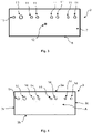
Figure 1 illustrates a profile view of a slot coating die according to one embodiment of the present invention. -
Figure 2 illustrates a front view of an upstream die part according to one embodiment of the present invention. -
Figure 3 illustrates a front view of a downstream die part according to one embodiment of the present invention. -
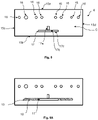
Figure 4 illustrates a front view of a blank shim plate according to one embodiment of the present invention. -
Figure 5 illustrates a front view of a restructured shim plate according one embodiment of the present invention. -
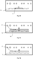
Figure 6A illustrates a front view of the superposition of a restructured shim plate and a die part comprising a filler material according to one embodiment of the present invention. -
Figure 6B illustrates a front view of the superposition of a restructured shim plate, a blank shim plate and a die part according to one embodiment of the present invention. -
Figure 7A illustrates a front view of the superposition of a restructured shim plate and a die part comprising a filler material according to another embodiment of the present invention. -
Figure 7B illustrates a front view of the superposition of a restructured shim plate, a blank shim plate and a die part according to another embodiment of the present invention. -
Figure 8A illustrates a front view of a patterned shim plate according to one embodiment of the present invention. -
Figure 8B illustrates a front view of a patterned shim plate according to another embodiment of the present invention. - The invention will now be described in more detail without limitation in the following description.
- In the following, reference is made to an initial slot coating die, which is a conventional slot coating die; and to a modified or restructured slot coating die, which is a slot coating die according to the invention and can be obtained by modifying the initial slot coating die.
- Each slot coating die described herein is assumed to be oriented in the vertical direction, as shown in
Figure 1 , the substrate to be coated being disposed under the slot coating die. The terms "lower", "upper", "vertical" and the like are used with reference to this configuration. - The terms "die" or "slot coating die" refer to a shaped body or block comprising one or more portions through which a fluid material is extruded or drawn.
- Therefore, the initial slot coating die comprises an
upstream die part 1 and adownstream die part 2. - The terms "upstream" and "downstream" refer to the direction of travel of the substrate relative to the slot coating die. The substrate travels from "upstream" to "downstream" relative to the slot coating die. To put it otherwise, the portion of the substrate situated upstream of the slot coating die has not been coated yet, whereas the portion of the substrate situated downstream of the slot coating die has already been coated.
- More particularly, with reference to
Figure 2 , theupstream die part 1 has afirst face 5 and a lower edge 6 (or coating edge). With reference toFigure 3 , thedownstream die part 2 has asecond face 7 and a lower edge 8 (or coating edge). Thefirst face 5 of theupstream die part 1 faces and is parallel to thesecond face 7 of thedownstream die part 2. Both faces are vertically oriented. Theupstream die part 1 and thedownstream die part 2 are spaced apart, so as to form an internal space, in which plates may be inserted. - The
lower edge 6 of theupstream die part 1 is preferably aligned with thelower edge 8 of the downstream die part 2 (as can be seen onFigure 1 ). In other terms, bothlower edges lower edges lower edge 6 of theupstream die part 1 faces thelower edge 8 of thedownstream die part 8. - The
upstream die part 1 may comprise one ormore fixation holes 9 on thefirst face 5 of the upstream die part 1 (eightfixation holes 9 are illustrated inFigure 2 ). Generally, the number offixation holes 9 is determined by the length of theupstream die part 1, the longer theupstream die part 1 is, themore fixation holes 9 are required. - Similarly, the
downstream die part 2 may comprise at least onefixation hole 11 on thesecond face 7 of the downstream die part 2 (eightfixation holes 11 are illustrated inFigure 3 ). Generally, the number of fixation holes 11 is determined by the length of thedownstream die part 2, the longer thedownstream die part 2 is, the more fixation holes 11 are required. - It is preferable that the fixation holes 9, 11 have a round shape, in other words a circular shape.
- The diameter of the fixation holes 9, 11 may be from 0.5 to 20 mm and preferably from 2 to 15 mm.
- It is also preferable that the number of
fixation holes 9 in theupstream die part 1 be equal to the number of fixation holes 11 in thedownstream die part 2, and that therespective fixation holes parts - When the slot coating die is assembled, fixation elements are preferably inserted into the
respective fixation holes parts - The initial slot coating die comprises at least one
fluid inlet 12 for introducing the fluid composition into the internal space between the upstream and downstream dieparts - According to some embodiments, the at least one
fluid inlet 12 is present on theupstream die part 1 of the slot coating die (not illustrated in the figures). - According to other embodiments, the at least one
fluid inlet 12 is present on thedownstream die part 2 of the slot coating die (as illustrated inFigure 3 ). Thedownstream die part 2 illustrated inFigure 3 comprises onefluid inlet 12, but the presence of more than one (for example two, three or four)fluid inlets 12 are also possible. - The initial slot coating die comprises a
horizontal channel 13 for channeling the fluid composition from the one or more fluid inlet(s) 12 to the outlet(s) of the slot coating die. - In the drawings, there is a single
horizontal channel 13, in fluid communication with all the fluid inlet(s) 12. However, it is also possible to provide two or more separatehorizontal channels 13, eachchannel 13 being in fluid communication with one or more fluid inlet(s) 12. - According to some embodiments, the
horizontal channel 13 is present on thefirst face 5 of theupstream die part 1 of the slot coating die (as illustrated inFigure 2 ). - According to other embodiments, the
horizontal channel 13 is present on thesecond face 7 of thedownstream die part 2 of the slot coating die (not illustrated in the figures). - As illustrated in
Figure 2 , thehorizontal channel 13 comprises an elongated, horizontal, section, configured for distributing fluid composition to a certain length of the die. In addition, thehorizontal channel 13 may comprise one ormore sections 13a perpendicular to the elongated section, so as to channel the fluid composition to the elongated section. Thehorizontal channel 13 has anupper edge 13b and alower edge 13c. - The volume of the
horizontal channel 13 may be from 100 to 100000 mm3, preferably from 100 to 20000 mm3 and preferably from 100 to 5000 mm3. By "volume of thehorizontal channel 13" is meant the volume of the elongated, horizontal, section and the volume of the one ormore sections 13a perpendicular to the elongated section. - According to some embodiments, the fluid inlet(s) 12 is(are) present on the die part (upstream or downstream) that comprises the
horizontal channel 13. In this case, the fluid inlet(s) 12 is(are) continuous with thehorizontal channel 13; or the fluid connection between the fluid inlet(s) 12 and thehorizontal channel 13 may be provided owing to a connecting channel present on a plate pressed against the die part. - According to other embodiments, and as illustrated in the drawings, the fluid inlet(s) 12 is(are) present on the die part (upstream or downstream) which is devoid of
horizontal channel 13. - The initial slot coating die may further comprise at least a
patterned shim plate 18 between theupstream die part 1 and thedownstream die part 2, as illustrated inFigures 8A and 8B . - The patterned
shim plate 18 may for example have a rectangular shape, comprise two faces (face E illustrated in the figures and face F not illustrated in the figures) and four edges. More particularly the patternedshim plate 18 may be defined by anupper edge 18a, alower edge 18b, and twolateral edges - It is preferable that the
upper edge 18a and thelower edge 18b be longer than the twolateral edges shim plate 18 be elongated in a horizontal direction. The exact dimensions of the patternedshim plate 18 depend on the dimensions of theupstream die part 1 and of thedownstream die part 2. - Therefore, the
upper edge 18a and thelower edge 18b can have a length e.g. from 1 to 500 cm, preferably from 5 to 300 cm, and more preferably from 10 to 100 cm. - The two
lateral edges - The patterned
shim plate 18 according to the invention may have a thickness from 0.1 to 1 mm; and preferably from 0.1 to 0.5 mm and more preferably from 0.1 to 0.2 mm (for example approximately 0.15 mm). By "thickness" is meant the distance between face E and face F of the patternedshim plate 18. - The patterned
shim plate 18 may also comprise at least one and preferably a plurality of fixation holes 19 through its entire thickness. The number, shape and positioning of the fixation holes 19 preferably correspond to number, shape and positioning of the fixation holes 9, 11 in the upstream and downstream dieparts - They are used to align and assemble the patterned
shim plate 18 with the other parts of the die, via fixation elements. - The patterned
shim plate 18 may further comprise at least onefluid hole 20 through the entire thickness of the patternedshim plate 18. The number, size and positioning of the fluid holes 20 then preferably correspond to the number, size and positioning of thefluid inlets 12. The fluid composition may be fed by thefluid inlets 12, flow through the corresponding fluid holes 20 on the patternedshim plate 18, and then flow through thehorizontal channel 13 when it is located on a different die part from thefluid inlets 12. Thus, the presence of the at least onefluid hole 20 on the patterned shim depends on the location of thehorizontal channel 13 and thefluid inlets 12. - The
lower edge 18b of the patternedshim plate 18 comprises at least one cut-out 21, preferably at least two, or at least three, or at least five cut-outs 21. For example, the patternedshim plate 18 may comprise from 1 to 3, or from 3 to 5; or from 5 to 7; or from 7 to 9; or from 9 to 11; or from 11 to 13; or from 13 to 15; or even more than 15 cut-outs 21. For example, the patternedshim plate 18 illustrated inFigure 8A comprises a single cut-out 21 while the patternedshim plate 18 illustrated inFigure 8B comprises three cut-outs 21. The cut-outs 21 may for example be rectangular-shaped or square-shaped. However, as the number of cut-outs 21 varies depending on the pattern, it is possible that the number of cut-outs 21 is more than 10, or more than 50, or even more than 100. - According to some embodiments, when more than one cut-
outs 21 are present on the patternedshim plate 18, all cut-outs have the same horizontal length (length in a direction parallel to theupper edge 18a and thelower edge 18b of the patterned shim plate 18). - According to other embodiments, when more than one cut-
outs 21 are present on the patternedshim plate 18, the length of the various cut-outs 21 may differ. - The (horizontal) length of each cut-out 21 may be for example from 1 mm to 250 cm; and preferably from 1 mm to 200 cm.
- The cut-
outs 21 are in fluid communication with the horizontal channel in the initial slot coating die. The cut-outs 21 form the outlets of the slot coating die. - Thus, in the initial slot coating die, the fluid composition flows from the fluid inlet(s) 20 to the
horizontal channel 13, and then exits the slot coating die from the cut-outs 21. - As described above, the different parts of the slot coating die can be secured together using various fastening mechanisms such as screws, bolts and pins.
- According to the invention, this initial slot coating die is modified so that the
horizontal channel 13 is at least partially blocked. In other terms, the fluid composition is prevented from flowing through at least part of thehorizontal channel 13. In some embodiments, only part of thehorizontal channel 13 is blocked. In that case, the fluid composition may flow through the unblocked part of thehorizontal channel 13 and then be dispensed through some or all of the cut-outs 21. Alternatively, the totality of thehorizontal channel 13 may be blocked. In that case, an additionalhorizontal channel 17 is provided to dispense the fluid composition to some or all of the cut-outs 21. - The modification of the slot coating die can be performed by:
- disassembling the slot coating die,
- at least partially blocking the
horizontal channel 13, for instance by adding filler material into thehorizontal channel 13 or by adding a blank shim plate, - optionally adding a restructured shim plate so as to introduce an additional
horizontal channel 17, and - reassembling the slot coating die.
- Other modifications may be made at the same time, but this is not necessarily the case. For example, the patterned
shim plate 18 can be replaced by another patternedshim plate 18. - As a result of the modification, the slot coating die comprises the parts described above, namely the upstream and downstream die
parts shim plate 18, and further comprises the following features described below. - In the modified slot coating die, the
horizontal channel 13 is configured so that thehorizontal channel 13 is at least partially blocked. - According to some embodiments, this is achieved by filling the
horizontal channel 13 with a filler material. Such filler material may be an organic material, an inorganic material or a metal. Preferably the filler material may be an inorganic material. For example, the filler material may be chosen from an epoxy resin, a polyurethane resin, a polyester resin, a metasilicate, tin, a peroxide and their mixtures. - According to some embodiments, the entire volume of the
horizontal channel 13 is filled with the filler material. In other words, the effective volume of the horizontal channel 13 (available for the fluid composition) becomes zero (or approximately zero) and as a result, during the coating process the fluid to be applied does not flow through thehorizontal channel 13. In this case, and as will be explained below, a restructured shim plate may be used to form an additionalhorizontal channel 17 different from thehorizontal channel 13. - According to other embodiments, only part of the
horizontal channel 13 is filled with a filler material. Thus, the volume of thehorizontal channel 13 is reduced relative to its initial volume. In this case, when all the parts of the slot coating die are assembled and when the fluid composition is introduced through a fluid inlet (as detailed below), the fluid composition flows through the non-filled portion of the horizontal channel only. - According to preferred embodiments, in case only part of the
horizontal channel 13 is filled with a filler material, such part is at least one, and more preferably both of the extremities of thehorizontal channel 13. Thus, one or both of the extremities of thehorizontal channel 13 may be filled with a filler material while the central part of thehorizontal channel 13 is devoid of filler material so that the fluid composition can flow through the non-filled part of thehorizontal channel 13. - The volume of the partially filled
horizontal channel 13 may be from 50 to 25000 mm3, preferably from 50 to 1000 mm3, and preferably from 50 to 500 mm3. The volume of the partially filledhorizontal channel 13 may depend on the viscosity of the fluid composition. For example, the higher the viscosity of the fluid composition, the bigger the volume of thehorizontal channel 13. - According to other embodiments, the
horizontal channel 13 is blocked with ablank shim plate 3 devoid of a horizontal channel. - Thus, the
blank shim plate 3 is inserted between the upstream and downstream dieparts horizontal channel 13. - By "shim plate" is meant a thin, substantially planar sheet of material.
- With reference to
Figure 4 , theblank shim plate 3 may have a substantially rectangular shape. It comprises two faces (face A illustrated in the figures and face B not illustrated in the figures) and may comprise four edges. More particularly theblank shim plate 3 may comprise an upper edge 3a, alower edge 3b, and twolateral edges blank shim plate 3 may be devoid of cut-outs and protrusions, in other words each edge of theblank shim plate 3 may be straight (linear). - It is preferable that the upper edge 3a and the
lower edge 3b be longer than the twolateral edges blank shim plate 3 be elongated in a horizontal direction. Naturally, the exact dimensions of theblank shim plate 3 depend on the dimensions of theupstream die part 1 and of thedownstream die part 2. - For example, the upper edge 3a and the
lower edge 3b can have a length from 1 to 500 cm, preferably from 5 to 300 cm, and more preferably from 10 to 100 cm. - The two
lateral edges - The
blank shim plate 3 may have a thickness from 0.1 to 5 mm; preferably from 0.5 to 5 mm; and more preferably from 0.5 to 1.5 mm. By "thickness" is meant the distance between the face A and the face B of theblank shim plate 3. - According to some embodiments, the patterned
shim plate 18 has the same thickness as theblank shim plate 3. - Alternatively, the patterned
shim plate 18 may have a different thickness from the thickness of theblank shim plate 3. In this case it is preferable that theblank shim plate 3 be thicker than the patternedshim plate 18. For example, theblank shim plate 3 can be thicker than the patternedshim plate 18 by 0.05 to 1 mm, preferably from 0.1 to 0.5 mm, and even more preferably from 0.1 to 0.25 mm. - The
blank shim plate 3 may further comprise at least one, preferablyseveral fixation holes 14 through its entire thickness. - The number, shape and positioning of the fixation holes 14 preferably correspond to number, shape and positioning of the fixation holes 9, 11 in the upstream and downstream die
parts - They are used to align and assemble the
blank shim plate 3 with the other parts of the die, via fixation elements. - The slot coating die may further comprise a restructured
shim plate 4 as illustrated inFigure 5 , located between the upstream die part and the downstream die part as illustrated inFigure 1 . More particularly, in case thehorizontal channel 13 is (preferably completely) filled with a filler material, the restructuredshim plate 4 is located so as to be in contact with the part (upstream or downstream) comprising thehorizontal channel 13. Alternatively, in case the slot coating die comprises ablank shim plate 3, theblank shim plate 3 is located between the restructuredshim plate 4 and thedie part 1, 2 (upstream or downstream) comprising thehorizontal channel 13. - The restructured
shim plate 4 may for example have a rectangular shape and comprises two faces (face C illustrated in the figures and face D not illustrated in the figures) and may comprise four edges. More particularly the restructuredshim plate 4 may be defined by anupper edge 15a, alower edge 15b, and twolateral edges - It is preferable that the
upper edge 15a and thelower edge 15b be longer than the twolateral edges shim plate 4 be elongated in a horizontal direction. It is even more preferable that the shape of the restructuredshim plate 4 be substantially the same as the shape of theblank shim plate 3. Naturally, as for theblank shim plate 3, the exact dimensions of the restructuredshim plate 4 depend on the dimensions of theupstream die part 1 and of thedownstream die part 2. - Therefore, the
upper edge 15a and thelower edge 15b can have a length e.g. from 1 to 500 cm, preferably from 5 to 300 cm, and more preferably from 10 to 100 cm. - The two
lateral edges - According to some embodiments, the
upper edge 15a of the restructuredshim plate 4 has the same length as the upper edge 3a of theblank shim plate 3. - The restructured
shim plate 4 according to the invention may have a thickness from 0.1 to 1 mm; and preferably from 0.2 to 0.5 mm. By "thickness" is meant the distance between face C and face D of the restructuredshim plate 4. - In some embodiments, the thickness of the restructured
shim plate 4 is greater than the thickness of the patterned shim plate. - The restructured
shim plate 4 may also comprise at least one, preferablyseveral fixation holes 16 through its entire thickness. The number, shape and positioning of the fixation holes 16 preferably correspond to number, shape and positioning of the fixation holes 9, 11 in the upstream and downstream dieparts - They are used to align and assemble the restructured
shim plate 4 with the other parts of the die, via fixation elements. - As illustrated in
Figure 5 , the restructuredshim plate 4 comprises a horizontally elongated opening which forms an additionalhorizontal channel 17. This additionalhorizontal channel 17 comprises an elongated, horizontal, section. In addition, it may comprise one ormore sections 17a perpendicular to the elongated section, so as to channel the fluid composition from the fluid inlet(s) 12 to the elongated section. The number ofsections 17a perpendicular to the elongated section on the restructuredshim plate 4 is preferably the same as the number of fluid inlet(s) 12. The additionalhorizontal channel 17 has anupper edge 17b and alower edge 17c. - According to some embodiments, this additional
horizontal channel 17 is formed by a through hole in the restructuredshim plate 4. In this case, the additionalhorizontal channel 17 is closed by two parts pressed on either side of the restructuredshim plate 4, such as adie part 1, 2 (upstream or downstream) comprising the (filled)horizontal channel 13 and the patternedshim plate 18; or such as theblank shim plate 3 and the patternedshim plate 18. - According to other embodiments, the additional
horizontal channel 17 is formed as a depression in the restructuredshim plate 4, which is not a through hole. In other words, the additionalhorizontal channel 17 is closed on one side by the restructuredshim plate 4 itself, and on the other side by thedie part 1, 2 (upstream or downstream) comprising the (filled)horizontal channel 13 or theblank shim plate 3 against which it is pressed. - In the above two cases, when all the parts of the slot coating die are assembled and when the fluid composition is introduced through the fluid inlet(s) 12, the fluid composition does not flow through with the
horizontal channel 13 but flows directly through the additionalhorizontal channel 17 before being dispensed to the outlet(s) of the slot coating die. - According to some embodiments, the additional
horizontal channel 17 has a volume which is lower than the volume of the (unblocked) horizontal channel 13 (in the initial slot coating die). By "volume of the additional horizontal channel" is meant the total volume of the elongated, horizontal, section and the volume of the one ormore sections 17a perpendicular to the elongated section if present. By "volume of the (unblocked)horizontal channel 13" is meant the total volume of the elongated, horizontal, section and the volume of the one ormore sections 13a perpendicular to the elongated section if present. - Such embodiment is illustrated in
Figures 6A and6B . InFigure 6A a restructuredshim 4 is superposed on a die part (downstream or upstream) comprising a horizontal channel 13 (illustrated with a dotted line) entirely filled with afiller material 18. InFigure 6B a restructuredshim 4 is superposed on a die part (downstream or upstream) comprising a horizontal channel 13 (illustrated with a dotted line) and ablank shim plate 3. In other words, theblank shim plate 3 is located between the die part (downstream or upstream) comprising ahorizontal channel 13 and the restructuredshim plate 4. - The smaller volume of the additional
horizontal channel 17 makes it possible to increase pressure during the application of the fluid composition while applying the same amount of the adhesive and also allows to retain a smaller amount of the adhesive when the slot coating die is not applying any fluid composition on the substrate (in other words, when the slot coating is not operating). As a result, the ghosting of the fluid composition on the substrate is reduced. - The volume of the additional
horizontal channel 17 may be from 50 to 25000 mm3, preferably from 50 to 1000 mm3, and preferably from 50 to 500 mm3. It goes without saying that the volume of this channel depends on the size of the slot coating die and the viscosity of the fluid composition to be applied. - According to preferred embodiments, the volume of the additional
horizontal channel 17 may be reduced relative to the volume of thehorizontal channel 13 by from 5 to 95 %, preferably from 10 to 90 %. - Alternatively or additionally, the distance between the
lower edge 17c of the additionalhorizontal channel 17 and thelower edge 15b of the restructuredshim plate 4 is different from, preferably higher than the distance between thelower edge 13c of thehorizontal channel 13 and thelower edge 6 of theupstream die part 1 if thehorizontal channel 13 is located on the upstream die part 1 (as illustrated inFigure 2 ), or thelower edge 8 of thedownstream die part 2 if thehorizontal channel 13 is located on the downstream die part 2 (not illustrated in figures). In other terms, the additionalhorizontal channel 17 is vertically offset (preferably upwards) relative to thehorizontal channel 13. - Such embodiment is illustrated in
Figures 7A and 7B . InFigure 7A a restructuredshim 4 is superposed on a die part (downstream or upstream) comprising a horizontal channel 13 (illustrated with a dotted line) entirely filled with afiller material 18. The additionalhorizontal channel 17 is located above thehorizontal channel 13 in the vertical direction. InFigure 7B a restructuredshim 4 is superposed on a die part (downstream or upstream) comprising a horizontal channel 13 (illustrated with a dotted line) and ablank shim plate 3. In other words, theblank shim plate 3 is located between the die part (downstream or upstream) comprising ahorizontal channel 13 and the restructuredshim plate 4. The additionalhorizontal channel 17 is located above thehorizontal channel 13. This offset makes it possible to reduce ghosting of the fluid composition on the substrate. - This vertical offset between the channels may be from 1 to 10 mm; and preferably from 1 to 5 mm. For example, this difference may be from 1 to 2 mm; or from 2 to 3 mm; or from 3 to 4 mm; or from 4 to 5 mm; or from 5 to 6 mm; or from 6 to 7 mm; or from 7 to 8 mm; or from 8 to 9 mm; or from 9 to 10 mm.
- The distance of the
lower edge 17c of the additionalhorizontal channel 17 and thelower edge 15b of the restructuredshim plate 4 may be from 2 mm to 50 mm, and preferably from 2 to 10 mm. - The distance between the
lower edge 13c of thehorizontal channel 13 and thelower edge 6 of theupstream die part 1 if thechannel 13 is located on the upstream die part 1 (as illustrated inFigure 2 ) or thelower edge 8 of thedownstream die part 2 if thechannel 13 is located on the downstream die part 2 (not illustrated in figures) may be from 1 to 40 mm and preferably from 1 to 5 mm. - According to preferred embodiments, the restructured
shim plate 4 may have the features of bothFigure 6A andFigure 7A . In other words, the additionalhorizontal channel 17 may have a volume which is lower than the volume of thehorizontal channel 13 and it may be vertically offset relative to thehorizontal channel 13. - Similarly, the restructured
shim plate 4 may have the features of bothFigure 6B and Figure 7B . - In some embodiments, the slot coating die of the invention comprises the following layered arrangement:
- one die
part horizontal channel 13; - the patterned
shim plate 18 pressed against said diepart - the
other die part shim plate 18. - In some embodiments, the slot coating die of the invention comprises the following layered arrangement:
- one die
part horizontal channel 13; - the restructured
shim plate 4 pressed against said diepart - the patterned
shim plate 18 pressed against the restructuredshim plate 4; - the
other die part shim plate 18. - In some embodiments, the slot coating die of the invention comprises the following layered arrangement:
- one die
part horizontal channel 13; - the
blank shim plate 3 pressed against said diepart - the restructured
shim plate 4 pressed against theblank shim plate 3; - the patterned
shim plate 18 pressed against the restructuredshim plate 4; - the
other die part shim plate 18. - Preferably, the
upstream die part 1 and thedownstream die part 2 can for example be manufactured from stainless steel. - Each of the
blank shim plate 3, restructuredshim plate 4 and patternedshim plate 18 can for example be manufactured from a material chosen from stainless steel, aluminum, ceramic, titanium, nickel, copper, tin, tungsten, molybdenum, alloys and/or combinations thereof. According to preferred embodiments, they are manufactured from stainless steel. According to preferred embodiments, these plates are manufactured from the same material. - In order to coat a substrate with the slot coating die of the present invention, the fluid composition is fed to the additional
horizontal channel 17 via the fluid inlet(s) 12 (if thehorizontal channel 13 is fully blocked); or the fluid composition is fed to the unblocked (e.g. unfilled) portion of the horizontal channel 13 (if it is not fully blocked); and the fluid composition is then dispensed through the outlet(s) of the slot coating die. The composition can be applied in the form of patterns, especially strips, depending on the shape, number and positioning of the outlet(s) formed by the one or more cut-outs 21. - The fluid composition may be introduced into the fluid inlet(s) 12 using for example a metering pump configured to pump and transport the pressurized fluid composition through a hose and into the fluid inlet(s) 12. During this step, the fluid composition may have a temperature from 25 to 250°C.
- The fluid composition is preferably an adhesive material. The adhesive material may for example comprise a rubber-based polymer such as a styrene block copolymer, butyl rubber and ethylene vinyl acetate. According to some preferred embodiments, the adhesive material is a wet-indicator adhesive material for a sanitary absorbent article, such as a diaper or an adult incontinence product.
- The substrate may be for example a film, or a woven or nonwoven material, which may for example be made of polypropylene, polyethylene, polyethylene terephthalate, polyamide, paper or any other cellulose-based material, natural fibers such as cotton fibers, and combinations thereof.
- The substrate may move from upstream to downstream. A lower part of the slot coating die may contact the substrate.
- The temperature of the fluid exiting the slot coating die and being applied onto the substrate can be from 30 to 350°C, and preferably from 100 to 200°C.
- In addition, the speed of the coating of the substrate may be from 5 to 800 m/min, and preferably from 100 to 500 m/min.
- The fluid applied on the substrate may have a thickness of 0.001 to 5 mm.
- According to some embodiments, the coating of a substrate with the slot coating die of the present invention may be a continuous process.
- According to other preferred embodiments, the coating of a substrate with the slot coating die of the present invention may be a discontinuous (intermittent) process.
- As indicated above, the present invention makes it possible to reduce the ghosting of the fluid composition on the substrate. Therefore, the ghosting length may be from 0 to 60 mm, preferably from 0 to 20 mm, more preferably from 0 to 10 mm, even more preferably from 0 to 5 mm. By "ghosting length" is meant the length of the fluid composition applied on the substrate adjacent an area of the substrate on which the fluid composition is sought to be applied.
- Since the ghosting phenomenon is highly dependent on the nature of the fluid composition and in particular on its viscosity, the present invention makes it possible to modify an existing slot coating die in order to reduce or suppress ghosting when it is observed.
- According to some embodiments, the ghosting phenomenon may occur for a fluid composition having a viscosity from 100 to 10000 cps, and preferably from 200 to 5000 cps.
- The following example illustrates the invention without limiting it.
- In this example, a wetness indicator adhesive was coated on the surface of a polyethylene film at a temperature of 90°C or 110°C and with a speed of 250 m/min.
- Coating of the substrate with the adhesive was achieved first by using a slot coating die comprising a blank shim plate and a restructured shim plate (Tests 1 to 7), then by using a slot coating die wherein the horizontal channel was filled with a filler material (mixture of organic peroxides and polyester resin) and comprising a restructured shim plate (Tests 8 to 12) and then by using a slot coating die devoid of filler material and devoid of blank shim plate and restructured shim plate (
Tests 13 to 14 - comparative). In all configurations, a patterned shim plate having a thickness of 0.15 mm was used. When a restructured shim plate was used, different vertical offset values relative to the horizontal channel were tested. - The adhesive was coated on the substrate at a quantity of 25 g of adhesive/m2, at a speed of 250 mpm.
- The coating of the substrate is a discontinuous (intermittent) process to form alternating 200 mm coated areas and 270 mm uncoated areas.
- The distance between the lower edge of the horizontal channel and the lower edge of the die part comprising the horizontal channel is 1 mm.
Test Blank shim plate Filler material Vertical offset (mm) Restructured shim thickness (mm) Application temperature (°C) Length of ghosting (mm) 1 Yes No 4 0.2 90 10 2 Yes No 4 0.2 110 10 3 Yes No 1 0.2 90 40-50 4 Yes No 1 0.2 110 20-40 5 Yes No 4 0.5 90 20-50 6 Yes No 4 0.5 110 20-40 7 Yes No 1 0.5 90 30-60 8 No Yes 4 0.2 90 10-15 9 No Yes 4 0.2 110 10-15 10 No Yes 1 0.2 90 40-50 11 No Yes 1 0.2 110 25-35 12 No Yes 4 0.5 90 20-30 13 No No 1 - 90 No cut-off 14 No No 1 - 110 No cut-off - No-cut-off: No uncoated substrate was observed between the areas of coated substrate.
- The ghosting length is measured by measuring the length of the fluid composition applied on the substrate adjacent the area of the substrate on which the fluid composition was applied.
wherein the method comprises modifying the initial slot coating die by at least partially blocking the horizontal channel so that the fluid composition is prevented from flowing through at least part of the horizontal channel, thus turning the initial slot coating die into the above slot coating die.
Claims (15)
- A slot coating die for applying a fluid composition on a substrate, comprising:- an upstream die part (1) having a first face (5);- a downstream die part (2) having a second face (7), the first face (5) of the upstream die part (1) facing and being parallel to the second face (7) of the downstream die part (2);wherein at least one of the upstream die part (1) and the downstream die part (2) comprises at least one fluid inlet (12) configured for making the fluid composition flow between the upstream die part (1) and the downstream die part (2), and wherein at least one of the upstream die part (1) and the downstream die part (2) comprises at least one horizontal channel (13) on the first face (5) or second face (6), wherein the horizontal channel (13) is at least partially blocked so that the fluid composition is prevented from flowing through at least part of the horizontal channel (13).
- The slot coating die according to claim 1, wherein at least part of the horizontal channel (13) is filled with a filler material, preferably an organic material, an inorganic material or a metal chosen from an epoxy resin, a polyurethane resin, a polyester resin, a metasilicate, tin, a peroxide and their mixtures.
- The slot coating die according to claim 1 or 2, comprising a blank shim plate (3) located between the upstream die part (1) and the downstream die part (2), the blank shim plate (3) being configured to block the horizontal channel (13) so as to prevent the fluid composition from flowing through the horizontal channel (13).
- The slot coating die according to any one of claims 1 to 3, comprising a restructured shim plate (4) located between the upstream die part (1) and the downstream die part (2), the restructured shim plate (4) comprising an additional horizontal channel (17) configured so that the fluid composition flows through said additional horizontal channel (17).
- The slot coating die according to claim 4, wherein the additional horizontal channel (17) has a volume which is lower than the volume of the horizontal channel (13).
- The slot coating die according to any one of claims 4 or 5, wherein the volume of the additional horizontal channel (17) is from 50 to 25000 mm3, preferably from 50 to 1000 mm3, and preferably from 50 to 500 mm3.
- The slot coating die according to any one of claims 4 to 6, wherein the additional horizontal channel (17) is vertically offset relative to the horizontal channel (13), and is preferably located above the horizontal channel (13).
- The slot coating die according to claim 7, wherein the additional horizontal channel (17) is at a distance from 2 mm to 50 mm, and preferably from 2 to 10 mm, from a lower edge (15b) of the restructured shim plate (4).
- The slot coating die according to any one of claims 4 to 8, wherein the thickness of the restructured shim (4) plate is from 0.1 to 1 mm; and preferably from 0.2 to 0.5 mm.
- The slot coating die according to claims 1 to 9, further comprising a patterned shim plate (18) between the upstream die part (1) and the downstream die part (2), the patterned shim plate (18) having a lower edge (18b), wherein the lower edge (18b) comprises at least one cut-out (21).
- A method for applying a fluid composition on a substrate by using the slot coating die according to any one of claims 1 to 10, the method comprising:- feeding the fluid composition to the at least one inlet (12);- making the fluid composition flow between the upstream die part (1) and the downstream die part (2);- dispensing the fluid composition onto the substrate from the slot coating die.
- The method according to claim 11, wherein the fluid composition is an adhesive material.
- The use of the slot coating die according to any one of claims 1 to 10 to reduce or prevent ghosting during a slot die coating process, wherein the slot die coating process comprises applying a fluid composition on a substrate by the slot coating die.
- A method of restructuring an initial slot coating die for applying a fluid composition on a substrate, the initial slot coating die comprising:- an upstream die part (1) having a first face (5);- a downstream die part (2) having a second face (7), the first face (5) of the upstream die part (1) facing and being parallel to the second face (7) of the downstream die part (2);wherein at least one of the upstream die part (1) and the downstream die part (2) comprises at least one fluid inlet (12) configured for making the fluid composition flow between the upstream die part (1) and the downstream die part (2), and wherein at least one of the upstream die part (1) and the downstream die part (2) comprises at least one horizontal channel (13) on the first face (5) or second face (6);
wherein the method comprises modifying the initial slot coating die by at least partially blocking the horizontal channel (13) so that the fluid composition is prevented from flowing through at least part of the horizontal channel (13), thus turning the initial slot coating die into a coating die according to any one of claims 1 to 10. - The method of claim 14, comprising a step of at least partly filling the horizontal channel (13) with a filler material; and/or of adding a blank shim plate (3) between the upstream die part (1) and the downstream die part (2) configured to block the horizontal channel (13) so as to prevent the fluid composition from flowing through the horizontal channel (13); and/or of adding a restructured shim plate (4) between the upstream die part (1) and the downstream die part (2), the restructured shim plate (4) comprising a an additional horizontal channel (17).
Priority Applications (2)
| Application Number | Priority Date | Filing Date | Title |
|---|---|---|---|
| EP21305674.0A EP4094846A1 (en) | 2021-05-24 | 2021-05-24 | Method for preventing ghosting in a slot coating die |
| PCT/EP2022/063863 WO2022248392A1 (en) | 2021-05-24 | 2022-05-23 | Method for preventing ghosting in a slot coating die |
Applications Claiming Priority (1)
| Application Number | Priority Date | Filing Date | Title |
|---|---|---|---|
| EP21305674.0A EP4094846A1 (en) | 2021-05-24 | 2021-05-24 | Method for preventing ghosting in a slot coating die |
Publications (1)
| Publication Number | Publication Date |
|---|---|
| EP4094846A1 true EP4094846A1 (en) | 2022-11-30 |
Family
ID=76325467
Family Applications (1)
| Application Number | Title | Priority Date | Filing Date |
|---|---|---|---|
| EP21305674.0A Withdrawn EP4094846A1 (en) | 2021-05-24 | 2021-05-24 | Method for preventing ghosting in a slot coating die |
Country Status (2)
| Country | Link |
|---|---|
| EP (1) | EP4094846A1 (en) |
| WO (1) | WO2022248392A1 (en) |
Citations (3)
| Publication number | Priority date | Publication date | Assignee | Title |
|---|---|---|---|---|
| US5709750A (en) * | 1995-03-15 | 1998-01-20 | Schiefer; Rolf | Apparatus for applying a liquid medium |
| US20010042507A1 (en) * | 2000-05-18 | 2001-11-22 | Josef Rothen | Device for applying adhesives |
| EP2679314A1 (en) * | 2012-06-29 | 2014-01-01 | National Taiwan University | Coating module |
-
2021
- 2021-05-24 EP EP21305674.0A patent/EP4094846A1/en not_active Withdrawn
-
2022
- 2022-05-23 WO PCT/EP2022/063863 patent/WO2022248392A1/en not_active Ceased
Patent Citations (3)
| Publication number | Priority date | Publication date | Assignee | Title |
|---|---|---|---|---|
| US5709750A (en) * | 1995-03-15 | 1998-01-20 | Schiefer; Rolf | Apparatus for applying a liquid medium |
| US20010042507A1 (en) * | 2000-05-18 | 2001-11-22 | Josef Rothen | Device for applying adhesives |
| EP2679314A1 (en) * | 2012-06-29 | 2014-01-01 | National Taiwan University | Coating module |
Also Published As
| Publication number | Publication date |
|---|---|
| WO2022248392A1 (en) | 2022-12-01 |
Similar Documents
| Publication | Publication Date | Title |
|---|---|---|
| EP2679313B1 (en) | Method and apparatus for applying adhesive on an elastic strand in a personal disposable hygiene product | |
| US6423140B1 (en) | Die set for preparing ABCABC multiple-stripe coating | |
| KR100984199B1 (en) | Die with multiple orifice slots | |
| US20140242283A1 (en) | Systems and methods for dispensing a fluid | |
| US20110083603A1 (en) | Curtain coater | |
| EP2516070A2 (en) | Method and apparatus for producing a non-uniform coating on a substrate | |
| EP0677777B1 (en) | Apparatus and method for controlling coating frowns in hopper coating | |
| US8187674B2 (en) | Method for coating with coating liquid, coating apparatuses for use therein, and method for designing the same | |
| JP2017131806A (en) | nozzle | |
| US9682392B2 (en) | Method for applying varying amounts or types of adhesive on an elastic strand | |
| US20110030613A1 (en) | Curtain coater | |
| WO2022248392A1 (en) | Method for preventing ghosting in a slot coating die | |
| EP3210675A1 (en) | Method, apparatus, and nozzle for applying varying amounts or types of adhesive on an elastic strand | |
| US20220410200A1 (en) | Use of a blank shim plate for preventing drooling in die slot coating | |
| JP2004160274A (en) | Method for forming coating film, apparatus for forming coating film, and method for producing sheet-like material with laminated film | |
| JP3338693B2 (en) | Die set for stripe coating and method thereof | |
| JP2552816B2 (en) | Stripe coating die coater | |
| JP2013099738A (en) | Curtain coater | |
| KR100286594B1 (en) | Coating method and coating device | |
| JP2016078012A (en) | Coating tool | |
| DE69920736T2 (en) | MOUNTING ARRANGEMENT FOR FLOATING OUTDOOR NOZZLE | |
| JP7715594B2 (en) | Application Nozzle | |
| RU237495U1 (en) | DISTRIBUTION DEVICE | |
| WO2021262580A1 (en) | Dual dispensing nozzle and method of using the same | |
| EP1732702B1 (en) | Nozzle for use in rotational casting apparatus |
Legal Events
| Date | Code | Title | Description |
|---|---|---|---|
| PUAI | Public reference made under article 153(3) epc to a published international application that has entered the european phase |
Free format text: ORIGINAL CODE: 0009012 |
|
| STAA | Information on the status of an ep patent application or granted ep patent |
Free format text: STATUS: THE APPLICATION HAS BEEN PUBLISHED |
|
| AK | Designated contracting states |
Kind code of ref document: A1 Designated state(s): AL AT BE BG CH CY CZ DE DK EE ES FI FR GB GR HR HU IE IS IT LI LT LU LV MC MK MT NL NO PL PT RO RS SE SI SK SM TR |
|
| STAA | Information on the status of an ep patent application or granted ep patent |
Free format text: STATUS: THE APPLICATION IS DEEMED TO BE WITHDRAWN |
|
| 18D | Application deemed to be withdrawn |
Effective date: 20230531 |