EP4094741A1 - Equipment for passive movement of the knee joint - Google Patents
Equipment for passive movement of the knee joint Download PDFInfo
- Publication number
- EP4094741A1 EP4094741A1 EP21744891.9A EP21744891A EP4094741A1 EP 4094741 A1 EP4094741 A1 EP 4094741A1 EP 21744891 A EP21744891 A EP 21744891A EP 4094741 A1 EP4094741 A1 EP 4094741A1
- Authority
- EP
- European Patent Office
- Prior art keywords
- motion
- patellar
- knee
- support
- multidirectional
- Prior art date
- Legal status (The legal status is an assumption and is not a legal conclusion. Google has not performed a legal analysis and makes no representation as to the accuracy of the status listed.)
- Granted
Links
Images



Classifications
-
- A—HUMAN NECESSITIES
- A61—MEDICAL OR VETERINARY SCIENCE; HYGIENE
- A61H—PHYSICAL THERAPY APPARATUS, e.g. DEVICES FOR LOCATING OR STIMULATING REFLEX POINTS IN THE BODY; ARTIFICIAL RESPIRATION; MASSAGE; BATHING DEVICES FOR SPECIAL THERAPEUTIC OR HYGIENIC PURPOSES OR SPECIFIC PARTS OF THE BODY
- A61H1/00—Apparatus for passive exercising; Vibrating apparatus; Chiropractic devices, e.g. body impacting devices, external devices for briefly extending or aligning unbroken bones
- A61H1/02—Stretching or bending or torsioning apparatus for exercising
- A61H1/0237—Stretching or bending or torsioning apparatus for exercising for the lower limbs
- A61H1/024—Knee
-
- A—HUMAN NECESSITIES
- A61—MEDICAL OR VETERINARY SCIENCE; HYGIENE
- A61F—FILTERS IMPLANTABLE INTO BLOOD VESSELS; PROSTHESES; DEVICES PROVIDING PATENCY TO, OR PREVENTING COLLAPSING OF, TUBULAR STRUCTURES OF THE BODY, e.g. STENTS; ORTHOPAEDIC, NURSING OR CONTRACEPTIVE DEVICES; FOMENTATION; TREATMENT OR PROTECTION OF EYES OR EARS; BANDAGES, DRESSINGS OR ABSORBENT PADS; FIRST-AID KITS
- A61F5/00—Orthopaedic methods or devices for non-surgical treatment of bones or joints; Nursing devices ; Anti-rape devices
- A61F5/01—Orthopaedic devices, e.g. long-term immobilising or pressure directing devices for treating broken or deformed bones such as splints, casts or braces
- A61F5/0102—Orthopaedic devices, e.g. long-term immobilising or pressure directing devices for treating broken or deformed bones such as splints, casts or braces specially adapted for correcting deformities of the limbs or for supporting them; Ortheses, e.g. with articulations
-
- A—HUMAN NECESSITIES
- A61—MEDICAL OR VETERINARY SCIENCE; HYGIENE
- A61F—FILTERS IMPLANTABLE INTO BLOOD VESSELS; PROSTHESES; DEVICES PROVIDING PATENCY TO, OR PREVENTING COLLAPSING OF, TUBULAR STRUCTURES OF THE BODY, e.g. STENTS; ORTHOPAEDIC, NURSING OR CONTRACEPTIVE DEVICES; FOMENTATION; TREATMENT OR PROTECTION OF EYES OR EARS; BANDAGES, DRESSINGS OR ABSORBENT PADS; FIRST-AID KITS
- A61F5/00—Orthopaedic methods or devices for non-surgical treatment of bones or joints; Nursing devices ; Anti-rape devices
- A61F5/01—Orthopaedic devices, e.g. long-term immobilising or pressure directing devices for treating broken or deformed bones such as splints, casts or braces
- A61F5/0102—Orthopaedic devices, e.g. long-term immobilising or pressure directing devices for treating broken or deformed bones such as splints, casts or braces specially adapted for correcting deformities of the limbs or for supporting them; Ortheses, e.g. with articulations
- A61F5/0123—Orthopaedic devices, e.g. long-term immobilising or pressure directing devices for treating broken or deformed bones such as splints, casts or braces specially adapted for correcting deformities of the limbs or for supporting them; Ortheses, e.g. with articulations for the knees
-
- A—HUMAN NECESSITIES
- A61—MEDICAL OR VETERINARY SCIENCE; HYGIENE
- A61H—PHYSICAL THERAPY APPARATUS, e.g. DEVICES FOR LOCATING OR STIMULATING REFLEX POINTS IN THE BODY; ARTIFICIAL RESPIRATION; MASSAGE; BATHING DEVICES FOR SPECIAL THERAPEUTIC OR HYGIENIC PURPOSES OR SPECIFIC PARTS OF THE BODY
- A61H1/00—Apparatus for passive exercising; Vibrating apparatus; Chiropractic devices, e.g. body impacting devices, external devices for briefly extending or aligning unbroken bones
- A61H1/02—Stretching or bending or torsioning apparatus for exercising
- A61H1/0237—Stretching or bending or torsioning apparatus for exercising for the lower limbs
- A61H1/0255—Both knee and hip of a patient, e.g. in supine or sitting position, the feet being moved together in a plane substantially parallel to the body-symmetrical plane
-
- A—HUMAN NECESSITIES
- A61—MEDICAL OR VETERINARY SCIENCE; HYGIENE
- A61H—PHYSICAL THERAPY APPARATUS, e.g. DEVICES FOR LOCATING OR STIMULATING REFLEX POINTS IN THE BODY; ARTIFICIAL RESPIRATION; MASSAGE; BATHING DEVICES FOR SPECIAL THERAPEUTIC OR HYGIENIC PURPOSES OR SPECIFIC PARTS OF THE BODY
- A61H9/00—Pneumatic or hydraulic massage
- A61H9/005—Pneumatic massage
- A61H9/0078—Pneumatic massage with intermittent or alternately inflated bladders or cuffs
-
- A—HUMAN NECESSITIES
- A61—MEDICAL OR VETERINARY SCIENCE; HYGIENE
- A61F—FILTERS IMPLANTABLE INTO BLOOD VESSELS; PROSTHESES; DEVICES PROVIDING PATENCY TO, OR PREVENTING COLLAPSING OF, TUBULAR STRUCTURES OF THE BODY, e.g. STENTS; ORTHOPAEDIC, NURSING OR CONTRACEPTIVE DEVICES; FOMENTATION; TREATMENT OR PROTECTION OF EYES OR EARS; BANDAGES, DRESSINGS OR ABSORBENT PADS; FIRST-AID KITS
- A61F5/00—Orthopaedic methods or devices for non-surgical treatment of bones or joints; Nursing devices ; Anti-rape devices
- A61F5/01—Orthopaedic devices, e.g. long-term immobilising or pressure directing devices for treating broken or deformed bones such as splints, casts or braces
- A61F5/0102—Orthopaedic devices, e.g. long-term immobilising or pressure directing devices for treating broken or deformed bones such as splints, casts or braces specially adapted for correcting deformities of the limbs or for supporting them; Ortheses, e.g. with articulations
- A61F2005/0132—Additional features of the articulation
- A61F2005/0146—Additional features of the articulation combining rotational and sliding movements, e.g. simulating movements of a natural joint
-
- A—HUMAN NECESSITIES
- A61—MEDICAL OR VETERINARY SCIENCE; HYGIENE
- A61F—FILTERS IMPLANTABLE INTO BLOOD VESSELS; PROSTHESES; DEVICES PROVIDING PATENCY TO, OR PREVENTING COLLAPSING OF, TUBULAR STRUCTURES OF THE BODY, e.g. STENTS; ORTHOPAEDIC, NURSING OR CONTRACEPTIVE DEVICES; FOMENTATION; TREATMENT OR PROTECTION OF EYES OR EARS; BANDAGES, DRESSINGS OR ABSORBENT PADS; FIRST-AID KITS
- A61F5/00—Orthopaedic methods or devices for non-surgical treatment of bones or joints; Nursing devices ; Anti-rape devices
- A61F5/01—Orthopaedic devices, e.g. long-term immobilising or pressure directing devices for treating broken or deformed bones such as splints, casts or braces
- A61F5/0102—Orthopaedic devices, e.g. long-term immobilising or pressure directing devices for treating broken or deformed bones such as splints, casts or braces specially adapted for correcting deformities of the limbs or for supporting them; Ortheses, e.g. with articulations
- A61F2005/0132—Additional features of the articulation
- A61F2005/0155—Additional features of the articulation with actuating means
-
- A—HUMAN NECESSITIES
- A61—MEDICAL OR VETERINARY SCIENCE; HYGIENE
- A61H—PHYSICAL THERAPY APPARATUS, e.g. DEVICES FOR LOCATING OR STIMULATING REFLEX POINTS IN THE BODY; ARTIFICIAL RESPIRATION; MASSAGE; BATHING DEVICES FOR SPECIAL THERAPEUTIC OR HYGIENIC PURPOSES OR SPECIFIC PARTS OF THE BODY
- A61H1/00—Apparatus for passive exercising; Vibrating apparatus; Chiropractic devices, e.g. body impacting devices, external devices for briefly extending or aligning unbroken bones
- A61H1/02—Stretching or bending or torsioning apparatus for exercising
- A61H2001/0203—Rotation of a body part around its longitudinal axis
-
- A—HUMAN NECESSITIES
- A61—MEDICAL OR VETERINARY SCIENCE; HYGIENE
- A61H—PHYSICAL THERAPY APPARATUS, e.g. DEVICES FOR LOCATING OR STIMULATING REFLEX POINTS IN THE BODY; ARTIFICIAL RESPIRATION; MASSAGE; BATHING DEVICES FOR SPECIAL THERAPEUTIC OR HYGIENIC PURPOSES OR SPECIFIC PARTS OF THE BODY
- A61H2201/00—Characteristics of apparatus not provided for in the preceding codes
- A61H2201/01—Constructive details
- A61H2201/0103—Constructive details inflatable
-
- A—HUMAN NECESSITIES
- A61—MEDICAL OR VETERINARY SCIENCE; HYGIENE
- A61H—PHYSICAL THERAPY APPARATUS, e.g. DEVICES FOR LOCATING OR STIMULATING REFLEX POINTS IN THE BODY; ARTIFICIAL RESPIRATION; MASSAGE; BATHING DEVICES FOR SPECIAL THERAPEUTIC OR HYGIENIC PURPOSES OR SPECIFIC PARTS OF THE BODY
- A61H2201/00—Characteristics of apparatus not provided for in the preceding codes
- A61H2201/01—Constructive details
- A61H2201/0192—Specific means for adjusting dimensions
-
- A—HUMAN NECESSITIES
- A61—MEDICAL OR VETERINARY SCIENCE; HYGIENE
- A61H—PHYSICAL THERAPY APPARATUS, e.g. DEVICES FOR LOCATING OR STIMULATING REFLEX POINTS IN THE BODY; ARTIFICIAL RESPIRATION; MASSAGE; BATHING DEVICES FOR SPECIAL THERAPEUTIC OR HYGIENIC PURPOSES OR SPECIFIC PARTS OF THE BODY
- A61H2201/00—Characteristics of apparatus not provided for in the preceding codes
- A61H2201/12—Driving means
- A61H2201/1207—Driving means with electric or magnetic drive
-
- A—HUMAN NECESSITIES
- A61—MEDICAL OR VETERINARY SCIENCE; HYGIENE
- A61H—PHYSICAL THERAPY APPARATUS, e.g. DEVICES FOR LOCATING OR STIMULATING REFLEX POINTS IN THE BODY; ARTIFICIAL RESPIRATION; MASSAGE; BATHING DEVICES FOR SPECIAL THERAPEUTIC OR HYGIENIC PURPOSES OR SPECIFIC PARTS OF THE BODY
- A61H2201/00—Characteristics of apparatus not provided for in the preceding codes
- A61H2201/12—Driving means
- A61H2201/1207—Driving means with electric or magnetic drive
- A61H2201/1215—Rotary drive
-
- A—HUMAN NECESSITIES
- A61—MEDICAL OR VETERINARY SCIENCE; HYGIENE
- A61H—PHYSICAL THERAPY APPARATUS, e.g. DEVICES FOR LOCATING OR STIMULATING REFLEX POINTS IN THE BODY; ARTIFICIAL RESPIRATION; MASSAGE; BATHING DEVICES FOR SPECIAL THERAPEUTIC OR HYGIENIC PURPOSES OR SPECIFIC PARTS OF THE BODY
- A61H2201/00—Characteristics of apparatus not provided for in the preceding codes
- A61H2201/14—Special force transmission means, i.e. between the driving means and the interface with the user
- A61H2201/1409—Hydraulic or pneumatic means
-
- A—HUMAN NECESSITIES
- A61—MEDICAL OR VETERINARY SCIENCE; HYGIENE
- A61H—PHYSICAL THERAPY APPARATUS, e.g. DEVICES FOR LOCATING OR STIMULATING REFLEX POINTS IN THE BODY; ARTIFICIAL RESPIRATION; MASSAGE; BATHING DEVICES FOR SPECIAL THERAPEUTIC OR HYGIENIC PURPOSES OR SPECIFIC PARTS OF THE BODY
- A61H2201/00—Characteristics of apparatus not provided for in the preceding codes
- A61H2201/16—Physical interface with patient
- A61H2201/1602—Physical interface with patient kind of interface, e.g. head rest, knee support or lumbar support
- A61H2201/164—Feet or leg, e.g. pedal
-
- A—HUMAN NECESSITIES
- A61—MEDICAL OR VETERINARY SCIENCE; HYGIENE
- A61H—PHYSICAL THERAPY APPARATUS, e.g. DEVICES FOR LOCATING OR STIMULATING REFLEX POINTS IN THE BODY; ARTIFICIAL RESPIRATION; MASSAGE; BATHING DEVICES FOR SPECIAL THERAPEUTIC OR HYGIENIC PURPOSES OR SPECIFIC PARTS OF THE BODY
- A61H2201/00—Characteristics of apparatus not provided for in the preceding codes
- A61H2201/16—Physical interface with patient
- A61H2201/1602—Physical interface with patient kind of interface, e.g. head rest, knee support or lumbar support
- A61H2201/164—Feet or leg, e.g. pedal
- A61H2201/1642—Holding means therefor
-
- A—HUMAN NECESSITIES
- A61—MEDICAL OR VETERINARY SCIENCE; HYGIENE
- A61H—PHYSICAL THERAPY APPARATUS, e.g. DEVICES FOR LOCATING OR STIMULATING REFLEX POINTS IN THE BODY; ARTIFICIAL RESPIRATION; MASSAGE; BATHING DEVICES FOR SPECIAL THERAPEUTIC OR HYGIENIC PURPOSES OR SPECIFIC PARTS OF THE BODY
- A61H2201/00—Characteristics of apparatus not provided for in the preceding codes
- A61H2201/16—Physical interface with patient
- A61H2201/1657—Movement of interface, i.e. force application means
- A61H2201/1664—Movement of interface, i.e. force application means linear
- A61H2201/1666—Movement of interface, i.e. force application means linear multidimensional
-
- A—HUMAN NECESSITIES
- A61—MEDICAL OR VETERINARY SCIENCE; HYGIENE
- A61H—PHYSICAL THERAPY APPARATUS, e.g. DEVICES FOR LOCATING OR STIMULATING REFLEX POINTS IN THE BODY; ARTIFICIAL RESPIRATION; MASSAGE; BATHING DEVICES FOR SPECIAL THERAPEUTIC OR HYGIENIC PURPOSES OR SPECIFIC PARTS OF THE BODY
- A61H2201/00—Characteristics of apparatus not provided for in the preceding codes
- A61H2201/16—Physical interface with patient
- A61H2201/1657—Movement of interface, i.e. force application means
- A61H2201/1671—Movement of interface, i.e. force application means rotational
-
- A—HUMAN NECESSITIES
- A61—MEDICAL OR VETERINARY SCIENCE; HYGIENE
- A61H—PHYSICAL THERAPY APPARATUS, e.g. DEVICES FOR LOCATING OR STIMULATING REFLEX POINTS IN THE BODY; ARTIFICIAL RESPIRATION; MASSAGE; BATHING DEVICES FOR SPECIAL THERAPEUTIC OR HYGIENIC PURPOSES OR SPECIFIC PARTS OF THE BODY
- A61H2201/00—Characteristics of apparatus not provided for in the preceding codes
- A61H2201/16—Physical interface with patient
- A61H2201/1657—Movement of interface, i.e. force application means
- A61H2201/1671—Movement of interface, i.e. force application means rotational
- A61H2201/1673—Multidimensional rotation
-
- A—HUMAN NECESSITIES
- A61—MEDICAL OR VETERINARY SCIENCE; HYGIENE
- A61H—PHYSICAL THERAPY APPARATUS, e.g. DEVICES FOR LOCATING OR STIMULATING REFLEX POINTS IN THE BODY; ARTIFICIAL RESPIRATION; MASSAGE; BATHING DEVICES FOR SPECIAL THERAPEUTIC OR HYGIENIC PURPOSES OR SPECIFIC PARTS OF THE BODY
- A61H2201/00—Characteristics of apparatus not provided for in the preceding codes
- A61H2201/50—Control means thereof
- A61H2201/5023—Interfaces to the user
- A61H2201/5043—Displays
-
- A—HUMAN NECESSITIES
- A61—MEDICAL OR VETERINARY SCIENCE; HYGIENE
- A61H—PHYSICAL THERAPY APPARATUS, e.g. DEVICES FOR LOCATING OR STIMULATING REFLEX POINTS IN THE BODY; ARTIFICIAL RESPIRATION; MASSAGE; BATHING DEVICES FOR SPECIAL THERAPEUTIC OR HYGIENIC PURPOSES OR SPECIFIC PARTS OF THE BODY
- A61H2201/00—Characteristics of apparatus not provided for in the preceding codes
- A61H2201/50—Control means thereof
- A61H2201/5056—Control means thereof pneumatically controlled
-
- A—HUMAN NECESSITIES
- A61—MEDICAL OR VETERINARY SCIENCE; HYGIENE
- A61H—PHYSICAL THERAPY APPARATUS, e.g. DEVICES FOR LOCATING OR STIMULATING REFLEX POINTS IN THE BODY; ARTIFICIAL RESPIRATION; MASSAGE; BATHING DEVICES FOR SPECIAL THERAPEUTIC OR HYGIENIC PURPOSES OR SPECIFIC PARTS OF THE BODY
- A61H2205/00—Devices for specific parts of the body
- A61H2205/10—Leg
- A61H2205/102—Knee
- A61H2205/104—Patella
Definitions
- the present patent document relates to automatic equipment for performing orthopedic and physiotherapeutic procedures for passive motion of the knee joint (patellofemoral and tibiofemoral).
- the knee is formed by two joint surfaces, the patellofemoral joint and the medial and lateral tibiofemoral joint.
- the patellofemoral joint is formed by the frontal and distal joint surface of the femur, called trochlea and by the kneecap, which encases into and slides along the trochlea. In this joint there are lower-upper and medial-lateral displacement motions.
- the tibiofemoral joint is formed by the distal end of the femur and by the proximal end of the tibia.
- this joint there are three pairs of motions, the flexion and extension (sagittal plane; medial-lateral axis of the knee), the internal and external rotation (transverse plane; axial or longitudinal axis) and the varus and valgus (frontal plane; anteroposterior axis).
- flexion and extension sagittal plane; medial-lateral axis of the knee
- internal and external rotation transverse plane; axial or longitudinal axis
- varus and valgus frontal plane; anteroposterior axis
- the knee is a joint with high incidence of lesions, and among the treatment possibilities, multidirectional patellar mobilization is a frequently indicated therapeutic conduct.
- the motion or passive mobilization relates to the procedures applied to the patient while he/she is at rest, that is, the motion is performed by the physiotherapist or by means of an external device.
- the term passive motion is used when greater amplitudes are used, for example, flexion and extension of the knee. Whereas the term passive mobilization refers to motions of lesser joint amplitude, such as patellar sliding.
- active motion relates to the motion performed actively by the patient, where the main objective is to produce motion by means of muscular contraction performed actively by the patient.
- the passive tibiofemoral motion and patellar mobilization are therapeutic procedures classified in the clinical ambit as manual therapy technique, and are commonly recommended and applied during rehabilitation.
- Several studies have presented a series of clinical benefits after applying manual therapy, including patellar mobilization and passive tibiofemoral motion, in patients with dysfunctions in the knee (Anwer, Alghadir, Zafar, & Brismee, 2018; Deyle et al., 2005; Deyle et al., 2000).
- Patellar mobilization and passive tibiofemoral motion are among procedures most recommended for treating patients with pain in the knee associated to hypo-patellar and tibiofemoral mobility (Mullaney & Fukunaga, 2016). These motions are typically applied by the physiotherapist. However, some of the components of the patellar mobilization can be taught to the patient to be performed at home. Patellar self-mobilization appears to be an effective method since it allows a high dose of patellar mobilization, performed by the very patient (Mullaney & Fukunaga, 2016). The kneecap is moved as far as the restriction region and oscillatory motions or pressure maintained are applied (Mullaney & Fukunaga, 2016).
- Passive tibiofemoral motion is harder for the patient to be able to perform alone at home.
- One option is to teach family members. But both patellar mobilization and passive tibiofemoral motion are hard to perform at home, chiefly due to the presence of pain, insecurity and the technique which is hard to understand.
- patellar and tibiofemoral mobility are two main concerns after surgical intervention in the knee.
- a kneecap moves 1cm medially (confidence interval of 95% from 0.8cm to 1.4cm) and 1.2cm laterally (confidence interval of 95% from 0.7cm to 1.8cm) (Ota, Nakashima, Morisaka, Ida, & Kawamura, 2008).
- the reduction of patellar mobility is associated with excessive proliferation of healing tissue (arthrofibrosis) and adherence between different tissue layers (Wilk et al., 2010).
- arthrofibrosis healing tissue
- adherence between different tissue layers Wilk et al., 2010.
- the patellar mobilization and the passive tibiofemoral motion are considered the main therapeutic procedures in the sense of avoiding hypo-patellar mobility and decreasing the amplitude of motion of the knee (Reinold, Wilk, Macrina, Dugas, & Cain, 2006; Tyler & Lung, 2012; Wilk, Davies, Mangine, & Malone, 1998; Wilk et al., 2010).
- Emphasis should be placed on the patellar mobilization to be performed in all the directions (lower, upper, medial and lateral), so that the passive tibiofemoral motion is performed up to the maximum amplitude available, and in high doses, covering the application several times per day (Reinold et al., 2006; Tyler & Lung, 2012).
- mobilization and passive joint motion appear to influence neural excitability associated to pain, promoting relief from pain (Courtney, Steffen, Fernandez-de-Las-Penas, Kim, & Chmell, 2016).
- the patellar mobilization and passive tibiofemoral motion procedure is performed manually by physiotherapists who work with clinical rehabilitation or by the patient him/herself upon professional recommendation.
- the clinical indication for carrying out the mobilization and passive motion procedure may vary from a few days up to several weeks, with daily intervals of 4 to 5 times in routines from 5 to 15 minutes each (Reinold et al., 2006; Tyler & Lung, 2012).
- the purpose of all this procedure is to improve/maintain the kneecap and/or to decrease the rigidity of the motion. Being a lengthy procedure, and applied during the course of the whole day, the physiotherapist is unable to accompany the patient for the entire rehabilitation process, placing the responsibility upon the individual and his/her family member/carers to carry out the procedures.
- document EP2114322 which describes a constructive arrangement for a knee immobilizer, with protection accessory for the kneecap; and also the document JP3693368 describes a knee brace that has one or more inflatable cushions to adjustably provide safe and comfortable support for the strap pressed against the leg; and also the document EP2825139 describes a device to protect the knee and the kneecap the enables and accompanies the active motion of the knee, and includes a contact cushion for protecting the kneecap while the knee is moved in flexion and extension.
- braces Today, the most common devices to control and assure immobilization are braces. Besides immobilizing the joint, some braces are also used to enable controlled motion, preventing undesirable amplitudes. For example, there are braces that prevent the knee from being moved at an amplitude greater than 30 degrees, so the device blocks the knee when it reaches this range of motion.
- the challenge in the evolution of these technologies relates to the difficulty in replacing the human operator in the treatment that requires mobilization of the knee joint as a whole, as well as reliable mobilization of the kneecap because it refers to a delicate movement, being in a hard-to-access place and requiring a steady grip, slippage errors can easily occur, which adversely affects the treatment. If we also consider the combination of other motions, the difficulty of correct application of the procedure increases.
- the multidirectional mobilizer of the knee is incorporating three motion units: knee flexion and extension motion unit; internal and external rotation motion unit of the knee; and a multidirectional patellar mobilization unit (lower-upper and medial-lateral), an external support for multidirectional patellar mobilizer and a control unit.
- the flexion and extension motion unit is comprised of a mechanical and electronic structure on which the leg rests during use thereof.
- the structure for the leg has at least two joints, one in the proximal region proximal of the femur (region of the hip) and another in the distal region of the femur (knee region), enabling the performance of flexion and extension motion of the leg.
- the structure has at least two supports to support the leg located at the back region of the thigh and at the back region of the leg (calf).
- the flexion and extension motion are performed passively from a motor coupled to the longitudinal axis of the unit.
- the internal and external rotation motion unit of the knee is comprised of a structure with a support for the leg and a support for the foot region (sole region) coupled to the knee flexion and extension motion unit.
- the leg support may be the same support for the leg of the flexion and extension motion unit with the addition of rotation on the longitudinal axis and of a leg fastening strap by the back part, enabling the performance of the internal and external rotation motion of the knee.
- the support for the sole region enables the comfortable positioning of the foot to the structure and the fastening of the motor for performing the rotation motion.
- the body of the motor is fastened to the structure of the flexion and extension motion unit and its axis is coupled to a trapezoidal screw of the internal and external rotation motion unit.
- the multidirectional patellar mobilization unit is comprised of a receptacle on which a retainer and an actuating element are disposed.
- the retainer is comprised of a rigid or semi-rigid structure that is positioned on the upper part of the knee and is coupled to the flexion and extension motion unit through fastening straps with height adjustment.
- the actuating element is comprised of a set of inflatable cuffs disposed such that the actuating element comes into contact with the kneecap region, but does not exert pressure thereon whilst not in operation.
- the set of inflatable cuffs of the actuating element is inflated and emptied according to the programming of the system (detailed ahead) from a fluid pump.
- the multidirectional patellar mobilization unit can be used in an integrated manner with the flexion and extension motion unit from the straps and side clips or used independently with the assistance of the support for multidirectional patellar mobilizer.
- the support for multidirectional patellar mobilizer is comprised of a single element that enables the coupling of the multidirectional patellar mobilizer in a manner similar to the flexion and extension motion unit from the side clip straps, but without the flexion-extension and rotation motion elements.
- the support for multidirectional patellar mobilizer enables the leg to be fastened at the suitable knee extension position for performing patellar mobilization.
- the structure has a support for the leg and thigh, on which the leg is fastened with two straps, one for each region, so as to maintain the leg in the extension position during mobilization.
- the control unit is comprised of an electro-electronic and pneumatic system.
- the electro-electronic system is characterized by performing the control of the operation of the device, in an automated manner and from the commands and parameters added by the user.
- the following are parts of the electro-electronic system: the activation drivers of the motors for performing flexion, extension and rotation movements; the activation drivers of the fluid pump and valves for performing lower-upper and medial-lateral patellar mobilization motion.
- the power source and the man-machine interface for controlling the adjustment parameters of the device are also parts of the electro-electronic system.
- the fluid pumps, the valves, the inflatable cuffs and the pneumatic connections are parts of the pneumatic system.
- the multidirectional patellar mobilization equipment is comprised of three motion units, according to Figure 1 , which are integrated into a single apparatus responsible for synchronizing the motions applied in the specific treatment of the patient.
- the position of use of the apparatus is compulsorily horizontal, with the base (1) positioned parallel to the horizontal plane, enabling the accommodation of the leg such that the hip remains near the proximal adjustment combination (3) and joint links (2) and that the thigh is supported on the back support of the thigh (6) and the calf is supported on the back support of the leg (14).
- the distal adjustment combination (4) should be adjusted through the device for adjustment locking (5) so that the sole face is duly supported on the foot support (9.1).
- the electronic and pneumatic control systems needed for the due activation of the electromechanical and pneumatic parts of the multidirectional mobilizer of the knee, as well as the man-machine interface through the local display (for example: display touchscreen, alphanumerical, etc.) or remote display (for example: smartphone).
- the flexion and extension motion unit (8) is comprised by the base (1) that is common to all the units, on which there are inserted a motor (8.2) coupled to a trapezoidal screw thread (8.1) and a displacement assembly (8.3), the displacement assembly is directed by guides (8.5) and connected to an articulated U-shaped tube (8.4).
- the internal and external rotation motion unit (9) of the knee is comprised of the base (1) which provides suitable support for the leg through the back support of the thigh (6), of the back support of the leg (14) and of the foot support (9.1).
- the foot support has a tightening strap for tibia (12) which is buckled at the distal region of the tibia in order to maintain the tibia in a neutral position relative to the internal-external rotation.
- the rotation device of the tibia is comprised of the foot support (9.1) coupled to a mobile flange of the turning ring (9.2), which is fastened to one of the plates of the system and a step motor (9.3) coupled to a trapezoidal screw (9.4) that transmits the rotation motion to a displacement assembly (9.5) fastened to the turning guide (9.6).
- the foot support (9.1) is coupled to the mobile flange of the turning ring (9.2) while the fastened flange of the turning ring (9.2) is fastened on the plate of the system, whereby the foot support turns freely while fastened on the plate.
- the foot support (9.1) is further connected by a guide pin to a slot on the guide turning plate (9.6) which is fastened to the displacement assembly (9.5), accordingly, when the step motor (9.3) is driven and turns the trapezoidal screw (9.4) displacing the displacement assembly (9.5) the guide pin of the foot support displaces radially inside the slot of the guide plate.
- the tibia turns internally (counter-clockwise) and upon retreating, it turns externally (clockwise) (9.7 and 9.8).
- the multidirectional patellar mobilization unit (10) is comprised of an inflatable cuff container (10.1) which is coupled to the base (1) through the tightening strap (11).
- a set of inflatable cuffs is located, comprised of at least one inflatable cuff.
- the representation (10.2, 10.3, 10.4, 10.5) shows the combination with four inflatable cuffs distributed in a way that they surround the knee joint.
- the inflatable cuffs are inserted inside internal containment chambers (10.6) upon containing the cuffs so as to control the direction of the fluid filling in the direction of the desired patellar mobilization (lower-back or medial-lateral).
- the fluid ducts of the cuffs are positioned laterally to the inflatable cuff container (21), enabling the pneumatic connection with the base (1) through the pneumatic connectors.
- a multidirectional patellar mobilization unit can be used in isolation with the assistance of the external support for multidirectional patellar mobilizer (15) which is comprised of the base for leg support and fastening the container (15), side fastening rods (10.7) and fastening straps of the thigh (16) and of the leg (18), besides the an electronic and pneumatic control unit (19) which has a man-machine interface through the local or remote display (20).
- the inflatable cuff container (10.1) is coupled to the external support for multidirectional patellar mobilizer through the side fastening rods (10.7) that have height adjustment by means of clips, butterflies or the like enabling the use in different anatomies of the knee.
- the external support for multidirectional patellar mobilizer contains an electronic and pneumatic control unit (19) specific for individualized use of the multidirectional patellar mobilizer.
- the electronic and pneumatic control unit (19) is connected to the inflatable cuffs (10.2, 10.3, 10.4, 10.5) through the pneumatic connectors (21) through which the flow of fluid enters and leaves the device through the valves and fluid pumps.
Landscapes
- Health & Medical Sciences (AREA)
- Life Sciences & Earth Sciences (AREA)
- Veterinary Medicine (AREA)
- Public Health (AREA)
- General Health & Medical Sciences (AREA)
- Animal Behavior & Ethology (AREA)
- Epidemiology (AREA)
- Pain & Pain Management (AREA)
- Physical Education & Sports Medicine (AREA)
- Rehabilitation Therapy (AREA)
- Vascular Medicine (AREA)
- Heart & Thoracic Surgery (AREA)
- Biomedical Technology (AREA)
- Engineering & Computer Science (AREA)
- Orthopedic Medicine & Surgery (AREA)
- Nursing (AREA)
- Prostheses (AREA)
- Rehabilitation Tools (AREA)
Abstract
Description
- The present patent document relates to automatic equipment for performing orthopedic and physiotherapeutic procedures for passive motion of the knee joint (patellofemoral and tibiofemoral).
- The knee is formed by two joint surfaces, the patellofemoral joint and the medial and lateral tibiofemoral joint. The patellofemoral joint is formed by the frontal and distal joint surface of the femur, called trochlea and by the kneecap, which encases into and slides along the trochlea. In this joint there are lower-upper and medial-lateral displacement motions. The tibiofemoral joint is formed by the distal end of the femur and by the proximal end of the tibia. In this joint there are three pairs of motions, the flexion and extension (sagittal plane; medial-lateral axis of the knee), the internal and external rotation (transverse plane; axial or longitudinal axis) and the varus and valgus (frontal plane; anteroposterior axis). During knee motions, there is a combination of these joint displacements. For example, during extension of the knee (putting the leg straight), the external rotation of the knee and the upper sliding of the kneecap occur simultaneously.
- The knee is a joint with high incidence of lesions, and among the treatment possibilities, multidirectional patellar mobilization is a frequently indicated therapeutic conduct. There are three procedures commonly used in clinical practice for recovery of the knee function: Immobilization, Motion or Passive Mobilization, and active Motion. Immobilization is necessary in some initial treatment phases, where, due to state of tissue healing, there can be no joint motion.
- The motion or passive mobilization relates to the procedures applied to the patient while he/she is at rest, that is, the motion is performed by the physiotherapist or by means of an external device. The term passive motion is used when greater amplitudes are used, for example, flexion and extension of the knee. Whereas the term passive mobilization refers to motions of lesser joint amplitude, such as patellar sliding. Lastly, active motion relates to the motion performed actively by the patient, where the main objective is to produce motion by means of muscular contraction performed actively by the patient.
- The passive tibiofemoral motion and patellar mobilization are therapeutic procedures classified in the clinical ambit as manual therapy technique, and are commonly recommended and applied during rehabilitation. Several studies have presented a series of clinical benefits after applying manual therapy, including patellar mobilization and passive tibiofemoral motion, in patients with dysfunctions in the knee (Anwer, Alghadir, Zafar, & Brismee, 2018; Deyle et al., 2005; Deyle et al., 2000). For example, two clinical assays (prospective monitoring study with two random intervention groups) showed that the use of manual therapy associated to exercise presents greater decrease of pain in the knee and functional improvement when compared to two different intervention approaches: placebo ultrasound (Deyle et al., 2000) and home exercise program (Deyle et al., 2005).
- A systematic review accompanied by meta-analysis (Anwer et al., 2018), comprising 494 patients with knee osteoarthrosis showed advantages of intervention with manual therapy compared to intervention exclusively with exercise. The patients who received only manual therapy presented in the short term greater reduction in pain, improvement in function and physical performance compared to the exercise group. Patellar mobilization and passive tibiofemoral motion were among the procedures most emphasized (Anwer et al., 2018).
- Patellar mobilization and passive tibiofemoral motion are among procedures most recommended for treating patients with pain in the knee associated to hypo-patellar and tibiofemoral mobility (Mullaney & Fukunaga, 2016). These motions are typically applied by the physiotherapist. However, some of the components of the patellar mobilization can be taught to the patient to be performed at home. Patellar self-mobilization appears to be an effective method since it allows a high dose of patellar mobilization, performed by the very patient (Mullaney & Fukunaga, 2016). The kneecap is moved as far as the restriction region and oscillatory motions or pressure maintained are applied (Mullaney & Fukunaga, 2016). Passive tibiofemoral motion is harder for the patient to be able to perform alone at home. One option is to teach family members. But both patellar mobilization and passive tibiofemoral motion are hard to perform at home, chiefly due to the presence of pain, insecurity and the technique which is hard to understand.
- One of the main concerns after surgical intervention in the knee is the decrease in patellar and tibiofemoral mobility (Harrison et al., 2013; Wilk, Macrina, & Reinold, 2010). On average, a kneecap moves 1cm medially (confidence interval of 95% from 0.8cm to 1.4cm) and 1.2cm laterally (confidence interval of 95% from 0.7cm to 1.8cm) (Ota, Nakashima, Morisaka, Ida, & Kawamura, 2008). The reduction of patellar mobility is associated with excessive proliferation of healing tissue (arthrofibrosis) and adherence between different tissue layers (Wilk et al., 2010). As a consequence, there is a decrease in the amplitude of tibiofemoral motion of the knee and decrease in the recruitment ability of the muscles of the quadriceps, essential conditions for adequate functioning of the knee joint.
- The patellar mobilization and the passive tibiofemoral motion are considered the main therapeutic procedures in the sense of avoiding hypo-patellar mobility and decreasing the amplitude of motion of the knee (Reinold, Wilk, Macrina, Dugas, & Cain, 2006; Tyler & Lung, 2012; Wilk, Davies, Mangine, & Malone, 1998; Wilk et al., 2010). Emphasis should be placed on the patellar mobilization to be performed in all the directions (lower, upper, medial and lateral), so that the passive tibiofemoral motion is performed up to the maximum amplitude available, and in high doses, covering the application several times per day (Reinold et al., 2006; Tyler & Lung, 2012). Additionally, mobilization and passive joint motion appear to influence neural excitability associated to pain, promoting relief from pain (Courtney, Steffen, Fernandez-de-Las-Penas, Kim, & Chmell, 2016).
- Today the patellar mobilization and passive tibiofemoral motion procedure is performed manually by physiotherapists who work with clinical rehabilitation or by the patient him/herself upon professional recommendation. The clinical indication for carrying out the mobilization and passive motion procedure may vary from a few days up to several weeks, with daily intervals of 4 to 5 times in routines from 5 to 15 minutes each (Reinold et al., 2006; Tyler & Lung, 2012). The purpose of all this procedure is to improve/maintain the kneecap and/or to decrease the rigidity of the motion. Being a lengthy procedure, and applied during the course of the whole day, the physiotherapist is unable to accompany the patient for the entire rehabilitation process, placing the responsibility upon the individual and his/her family member/carers to carry out the procedures. However, the patients and their carers are not always proficient at performing said procedure, either through concern about handling the recently-operated knee or on which he/she feels pain, or from forgetfulness. Furthermore, self-mobilization appears not to allow the necessary relaxation of the quadriceps musculature, especially the rectus femoris muscle, causing protective contraction. As a consequence, this muscle causes compression of the kneecap and decreases its ability to move.
- Since there is a strong dependency on the skill of the professional, or of the patient in carrying out the treatment adequately and with the necessary frequency, this treatment ends up not achieving the desired result, whereby contributing to the post-operation complications referred to.
- Accordingly, in order to solve the problems cited above, eliminating the factor of uncertainty in the efficiency of the treatment owing to the dependency on the professional's skill, various semiautomatic and automatic apparatuses have been developed to perform the physiotherapeutic treatments in the knee area, without the need for constant professional supervision.
- From prior art, it is possible to cite document
EP2114322 , which describes a constructive arrangement for a knee immobilizer, with protection accessory for the kneecap; and also the documentJP3693368 EP2825139 describes a device to protect the knee and the kneecap the enables and accompanies the active motion of the knee, and includes a contact cushion for protecting the kneecap while the knee is moved in flexion and extension. - Today, the most common devices to control and assure immobilization are braces. Besides immobilizing the joint, some braces are also used to enable controlled motion, preventing undesirable amplitudes. For example, there are braces that prevent the knee from being moved at an amplitude greater than 30 degrees, so the device blocks the knee when it reaches this range of motion.
- In general, the technologies developed to date focused on eliminating the uncertainties and problems in physiotherapeutic treatment of the knee, caused by the imprecision in performing the treatment, either by the patient or by the professional. Such uncertainty cannot be controlled with efficiency when it depends on the human factor involved.
- The challenge in the evolution of these technologies relates to the difficulty in replacing the human operator in the treatment that requires mobilization of the knee joint as a whole, as well as reliable mobilization of the kneecap because it refers to a delicate movement, being in a hard-to-access place and requiring a steady grip, slippage errors can easily occur, which adversely affects the treatment. If we also consider the combination of other motions, the difficulty of correct application of the procedure increases.
- It is the object of the present invention to provide a device for performing multidirectional mobilization of the knee joint - both patellofemoral and tibiofemoral - in an automated and non-invasive manner, for post-surgery rehabilitation treatment and conservative (non-surgical) treatment of the knee joint.
- According to the invention, the multidirectional mobilizer of the knee is incorporating three motion units: knee flexion and extension motion unit; internal and external rotation motion unit of the knee; and a multidirectional patellar mobilization unit (lower-upper and medial-lateral), an external support for multidirectional patellar mobilizer and a control unit.
- The flexion and extension motion unit is comprised of a mechanical and electronic structure on which the leg rests during use thereof. The structure for the leg has at least two joints, one in the proximal region proximal of the femur (region of the hip) and another in the distal region of the femur (knee region), enabling the performance of flexion and extension motion of the leg. The structure has at least two supports to support the leg located at the back region of the thigh and at the back region of the leg (calf). The flexion and extension motion are performed passively from a motor coupled to the longitudinal axis of the unit.
- The internal and external rotation motion unit of the knee is comprised of a structure with a support for the leg and a support for the foot region (sole region) coupled to the knee flexion and extension motion unit. The leg support may be the same support for the leg of the flexion and extension motion unit with the addition of rotation on the longitudinal axis and of a leg fastening strap by the back part, enabling the performance of the internal and external rotation motion of the knee. The support for the sole region enables the comfortable positioning of the foot to the structure and the fastening of the motor for performing the rotation motion. The body of the motor is fastened to the structure of the flexion and extension motion unit and its axis is coupled to a trapezoidal screw of the internal and external rotation motion unit.
- The multidirectional patellar mobilization unit is comprised of a receptacle on which a retainer and an actuating element are disposed. The retainer is comprised of a rigid or semi-rigid structure that is positioned on the upper part of the knee and is coupled to the flexion and extension motion unit through fastening straps with height adjustment. The actuating element is comprised of a set of inflatable cuffs disposed such that the actuating element comes into contact with the kneecap region, but does not exert pressure thereon whilst not in operation. The set of inflatable cuffs of the actuating element is inflated and emptied according to the programming of the system (detailed ahead) from a fluid pump. When the chambers are driven individually, the actuating element comes into contact with the side, lower and back edges of the kneecap and, from the pressure exerted on the edge, the multidirectional motions (frontal-upper and medial-lateral) are performed. The multidirectional patellar mobilization unit can be used in an integrated manner with the flexion and extension motion unit from the straps and side clips or used independently with the assistance of the support for multidirectional patellar mobilizer.
- The support for multidirectional patellar mobilizer is comprised of a single element that enables the coupling of the multidirectional patellar mobilizer in a manner similar to the flexion and extension motion unit from the side clip straps, but without the flexion-extension and rotation motion elements. The support for multidirectional patellar mobilizer enables the leg to be fastened at the suitable knee extension position for performing patellar mobilization. The structure has a support for the leg and thigh, on which the leg is fastened with two straps, one for each region, so as to maintain the leg in the extension position during mobilization.
- The control unit is comprised of an electro-electronic and pneumatic system. The electro-electronic system is characterized by performing the control of the operation of the device, in an automated manner and from the commands and parameters added by the user. The following are parts of the electro-electronic system: the activation drivers of the motors for performing flexion, extension and rotation movements; the activation drivers of the fluid pump and valves for performing lower-upper and medial-lateral patellar mobilization motion. The power source and the man-machine interface for controlling the adjustment parameters of the device are also parts of the electro-electronic system. The fluid pumps, the valves, the inflatable cuffs and the pneumatic connections are parts of the pneumatic system.
- The description below and accompanying drawings, for example, will clarify the understanding of the object of the present application.
-
Figure 1 presents a schematic drawing of the three motion units integrated in perspective. -
Figure 2 presents a schematic drawing of the three motion units integrated in side view. -
Figure 3 presents a detailed schematic drawing of the rotation device in perspective. -
Figure 4 presents a detailed schematic drawing of the flexion and extension device. -
Figure 5 presents a detailed schematic drawing of the rotation device in side view. -
Figure 6 presents a detailed schematic drawing of the rotation device with internal rotation. -
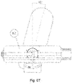
Figure 7 presents a detailed schematic drawing of the rotation device with external rotation. -
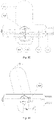
Figure 8 presents a schematic drawing of the patellar mobilizer and external support for the patellar mobilizer. -
Figure 9 presents a detailed schematic drawing of the inflatable cuff container. -
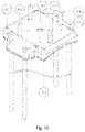
Figure 10 presents a detailed schematic drawing of the inflatable cuff container with side support rods. - As illustrated in the drawings, the multidirectional patellar mobilization equipment is comprised of three motion units, according to
Figure 1 , which are integrated into a single apparatus responsible for synchronizing the motions applied in the specific treatment of the patient. The position of use of the apparatus is compulsorily horizontal, with the base (1) positioned parallel to the horizontal plane, enabling the accommodation of the leg such that the hip remains near the proximal adjustment combination (3) and joint links (2) and that the thigh is supported on the back support of the thigh (6) and the calf is supported on the back support of the leg (14). For due accommodation of the leg and, considering the different anatomies and statures of the users, the distal adjustment combination (4) should be adjusted through the device for adjustment locking (5) so that the sole face is duly supported on the foot support (9.1). On the base (1) there are inserted the electronic and pneumatic control systems needed for the due activation of the electromechanical and pneumatic parts of the multidirectional mobilizer of the knee, as well as the man-machine interface through the local display (for example: display touchscreen, alphanumerical, etc.) or remote display (for example: smartphone). - The flexion and extension motion unit (8) is comprised by the base (1) that is common to all the units, on which there are inserted a motor (8.2) coupled to a trapezoidal screw thread (8.1) and a displacement assembly (8.3), the displacement assembly is directed by guides (8.5) and connected to an articulated U-shaped tube (8.4). When the motor (8.2) is driven the trapezoidal screw thread (8.1) transmits the rotation to the displacement assembly (8.3) which moves along the screw, the guides (8.5) restrict the motion of the displacement assembly only in a linear direction, upon moving, the assembly connected to the articulated U-shaped tube (8.4) which is part of a mechanism formed by tubes (3) and (4) and links (2), transfers the motion of one degree of freedom to two degrees of freedom whereby flexing the knee forward and extending it upon return.
- The internal and external rotation motion unit (9) of the knee is comprised of the base (1) which provides suitable support for the leg through the back support of the thigh (6), of the back support of the leg (14) and of the foot support (9.1). The foot support has a tightening strap for tibia (12) which is buckled at the distal region of the tibia in order to maintain the tibia in a neutral position relative to the internal-external rotation. The rotation device of the tibia is comprised of the foot support (9.1) coupled to a mobile flange of the turning ring (9.2), which is fastened to one of the plates of the system and a step motor (9.3) coupled to a trapezoidal screw (9.4) that transmits the rotation motion to a displacement assembly (9.5) fastened to the turning guide (9.6). To perform the operation of rotation of the tibia the foot support (9.1) is coupled to the mobile flange of the turning ring (9.2) while the fastened flange of the turning ring (9.2) is fastened on the plate of the system, whereby the foot support turns freely while fastened on the plate. The foot support (9.1) is further connected by a guide pin to a slot on the guide turning plate (9.6) which is fastened to the displacement assembly (9.5), accordingly, when the step motor (9.3) is driven and turns the trapezoidal screw (9.4) displacing the displacement assembly (9.5) the guide pin of the foot support displaces radially inside the slot of the guide plate. In advancing the displacement assembly, the tibia turns internally (counter-clockwise) and upon retreating, it turns externally (clockwise) (9.7 and 9.8).
- The multidirectional patellar mobilization unit (10) is comprised of an inflatable cuff container (10.1) which is coupled to the base (1) through the tightening strap (11). In the lower part of the inflatable cuff container (10.1) a set of inflatable cuffs is located, comprised of at least one inflatable cuff. The representation (10.2, 10.3, 10.4, 10.5) shows the combination with four inflatable cuffs distributed in a way that they surround the knee joint. The inflatable cuffs are inserted inside internal containment chambers (10.6) upon containing the cuffs so as to control the direction of the fluid filling in the direction of the desired patellar mobilization (lower-back or medial-lateral). The fluid ducts of the cuffs are positioned laterally to the inflatable cuff container (21), enabling the pneumatic connection with the base (1) through the pneumatic connectors.
- This constructive form enables the patellar mobilization device to be used individually, that is, a multidirectional patellar mobilization unit can be used in isolation with the assistance of the external support for multidirectional patellar mobilizer (15) which is comprised of the base for leg support and fastening the container (15), side fastening rods (10.7) and fastening straps of the thigh (16) and of the leg (18), besides the an electronic and pneumatic control unit (19) which has a man-machine interface through the local or remote display (20). The inflatable cuff container (10.1) is coupled to the external support for multidirectional patellar mobilizer through the side fastening rods (10.7) that have height adjustment by means of clips, butterflies or the like enabling the use in different anatomies of the knee. The external support for multidirectional patellar mobilizer contains an electronic and pneumatic control unit (19) specific for individualized use of the multidirectional patellar mobilizer. The electronic and pneumatic control unit (19) is connected to the inflatable cuffs (10.2, 10.3, 10.4, 10.5) through the pneumatic connectors (21) through which the flow of fluid enters and leaves the device through the valves and fluid pumps.
Claims (1)
- EQUIPMENT FOR PASSIVE MOTION OF THE KNEE JOINT comprised of three motion units integrated into a single apparatus responsible for synchronizing the motions applied in the specific treatment of the patient with dysfunction of the knee characterized by comprising motion unit flexion and extension (8), internal and external rotation motion unit (9), multidirectional patellar mobilization unit (10) mounted on a base (1) and external support for multidirectional patellar mobilizer (15); and said base (1) positioned parallel to the horizontal plane, so as to enable accommodation of the leg such that the hip remains near the proximal adjustment combination (3) and joint links (2) and such that the thigh is supported on the back support of the thigh (6) and the calf is supported on the back support of the leg (14) and further comprises distal adjustment combination (4) adjustable by means of the device for adjustment locking (5) so as to enable the sole face to be supported on the foot support (9.1); said base (1) provides the electronic, pneumatic control and man-machine interface systems through local or remote display; said flexion and extension motion unit (8) mounted on the base (1) provides a motor (8.2) coupled to a trapezoidal screw thread (8.1) and a displacement assembly (8.3), the displacement assembly is directed by guides (8.5) and connected to an articulated U-shaped tube (8.4) such that when the motor (8.2) is driven, the trapezoidal screw thread (8.1) transmits the rotation to the displacement assembly (8.3) such that same moves along the screw and such that the guides (8.5) enable the motion of the displacement assembly only in a linear direction; the assembly connected to the articulated U-shaped tube (8.4) which makes up a mechanism formed by tubes (3) and (4) and links (2), is mounted such that upon moving, it transfers the motion of one degree of freedom to two degrees of freedom; and said internal and external rotation motion unit (9) of the knee mounted on the base (1) comprises a tightening strap for the tibia (12) on the foot support (9.1) disposed such that it is buckled to the distal region of the tibia and said foot support (9.1) provides a mobile flange of the turning ring (9.2), which is fastened to one of the plates of the system and a step motor (9.3) coupled to a trapezoidal screw (9.4) which transmits the rotation motion to a displacement assembly (9.5) fastened to the turning guide (9.6); and said foot support (9.1) is coupled to the mobile flange of the turning ring (9.2) and the fastened flange of the turning ring (9.2) is fastened on the plate of the system, such that the foot support turns freely while fastened on the plate; and further, said foot support (9.1) which is fastened to the displacement assembly (9.5), such that when the step motor (9.3) is driven and turns the trapezoidal screw (9.4) displacing the displacement assembly (9.5) the guide pin of the foot support displaces radially inside of the slot of the guide plate; said multidirectional patellar mobilization unit (10) is comprised by an inflatable cuff container (10.1) which is coupled to the base (1) by means of the tightening strap (11) and on the lower part of the inflatable cuff container (10.1) there is disposed the set of inflatable cuffs (10.2, 10.3, 10.4, 10.5) distributed such that they surround the knee joint and the inflatable cuffs are inserted inside internal containment chambers (10.6) upon containing cuffs such that control the direction of the fluid filling and the fluid ducts of the cuffs are positioned laterally to the inflatable cuff container (21), comprising a pneumatic connection with the base (1) by means of pneumatic connectors; and said external support for multidirectional patellar mobilizer (15) comprised by the base for leg support and for fastening the container (15), side fastening rods (10.7) and fastening straps of the thigh (16) and of the leg (18), besides the an electronic and pneumatic control unit (19) which provides a man-machine interface through the local or remote display (20) and an inflatable cuff container (10.1) coupled to the external support for multidirectional patellar mobilizer by means of the side fastening rods (10.7) which provides height adjustment by means of clips; and said external support for multidirectional patellar mobilizer (15) provides an electronic and pneumatic control unit (19) connected to the set of inflatable cuffs (10.2, 10.3, 10.4, 10.5) by means of pneumatic connectors (21).
Applications Claiming Priority (2)
| Application Number | Priority Date | Filing Date | Title |
|---|---|---|---|
| BR102020001512-5A BR102020001512B1 (en) | 2020-01-23 | Equipment for passive movement of the knee joint. | |
| PCT/BR2021/050038 WO2021146790A1 (en) | 2020-01-23 | 2021-01-25 | Equipment for passive movement of the knee joint |
Publications (3)
| Publication Number | Publication Date |
|---|---|
| EP4094741A1 true EP4094741A1 (en) | 2022-11-30 |
| EP4094741A4 EP4094741A4 (en) | 2024-06-12 |
| EP4094741B1 EP4094741B1 (en) | 2025-05-28 |
Family
ID=76993392
Family Applications (1)
| Application Number | Title | Priority Date | Filing Date |
|---|---|---|---|
| EP21744891.9A Active EP4094741B1 (en) | 2020-01-23 | 2021-01-25 | Equipment for passive movement of the knee joint |
Country Status (7)
| Country | Link |
|---|---|
| US (1) | US12453672B2 (en) |
| EP (1) | EP4094741B1 (en) |
| CA (1) | CA3165349A1 (en) |
| ES (1) | ES3037583T3 (en) |
| PL (1) | PL4094741T3 (en) |
| PT (1) | PT4094741T (en) |
| WO (1) | WO2021146790A1 (en) |
Families Citing this family (2)
| Publication number | Priority date | Publication date | Assignee | Title |
|---|---|---|---|---|
| CN113633510A (en) * | 2021-07-29 | 2021-11-12 | 周媛 | Lower body auxiliary recovery device for rehabilitation |
| CN116712313B (en) * | 2023-07-06 | 2026-02-24 | 中国人民解放军陆军军医大学第二附属医院 | Patella pushing auxiliary device |
Family Cites Families (18)
| Publication number | Priority date | Publication date | Assignee | Title |
|---|---|---|---|---|
| DE67282C (en) * | 1892-02-23 | 1893-03-15 | Dr. med. SCHUCKELT, prakt. Arzt, in Bad Schmiedeberg, Bez. Halle | Apparatus for straightening crooked knee joints |
| US4603687A (en) * | 1983-08-08 | 1986-08-05 | Greenwood Eugene C | Continuous passive motion orthopedic device |
| US4665899A (en) | 1984-09-27 | 1987-05-19 | Joint Mobilizer Systems Corp. | Apparatus for articulating the knee and hip joints |
| US5228432A (en) * | 1991-09-16 | 1993-07-20 | Jace Systems, Inc. | Continuous passive motion orthosis device for a limb |
| US5325849A (en) | 1992-06-01 | 1994-07-05 | Rugo Eric P | Continuous passive motion device |
| DE69621426T2 (en) * | 1995-02-15 | 2002-12-12 | Dj Orthopedics, Llc | Knee orthosis with an inflatable cushion that surrounds the patella |
| JP3443368B2 (en) | 1999-07-08 | 2003-09-02 | 株式会社オートネットワーク技術研究所 | Electronic unit connection structure |
| US7309320B2 (en) | 2004-09-17 | 2007-12-18 | Ana-Tek, Llc | Apparatus and method for supporting and continuously flexing a jointed limb |
| WO2008100486A2 (en) | 2007-02-12 | 2008-08-21 | Ossur Hf | Orthopedic brace and component for use therewith |
| BRPI1015791A8 (en) | 2010-04-07 | 2018-02-27 | Paulo Augusto Loncarovich Gomes Me | knee or hip post traumatic therapy unit with passive leg extension and flexion system |
| US9125789B2 (en) | 2011-03-11 | 2015-09-08 | Felix M. Garcia | Knee extension assist device |
| US9108080B2 (en) * | 2011-03-11 | 2015-08-18 | For You, Inc. | Orthosis machine |
| US9113998B2 (en) | 2012-03-13 | 2015-08-25 | Ossur Hf | Patellofemoral device and method for using the same |
| US20140094721A1 (en) * | 2012-09-28 | 2014-04-03 | Ibrahima Diallo | Device and Method for Knee Rehabilitation |
| US10420691B2 (en) * | 2016-02-24 | 2019-09-24 | Richard Stewart | Knee range of motion device utilizing tangential joint translation and distraction |
| CN105796284A (en) * | 2016-04-27 | 2016-07-27 | 东莞市旭特机器人股份有限公司 | Intelligent knee joint training instrument |
| US11707374B2 (en) * | 2019-05-31 | 2023-07-25 | Bryan E. Kilbey | Inflatable flexion-correcting knee brace |
| CN110604673B (en) * | 2019-09-18 | 2024-11-05 | 上海理工大学 | A sports-based rehabilitation treatment training device for patellar adhesion |
-
2021
- 2021-01-25 PT PT217448919T patent/PT4094741T/en unknown
- 2021-01-25 WO PCT/BR2021/050038 patent/WO2021146790A1/en not_active Ceased
- 2021-01-25 ES ES21744891T patent/ES3037583T3/en active Active
- 2021-01-25 EP EP21744891.9A patent/EP4094741B1/en active Active
- 2021-01-25 US US17/794,674 patent/US12453672B2/en active Active
- 2021-01-25 PL PL21744891.9T patent/PL4094741T3/en unknown
- 2021-01-25 CA CA3165349A patent/CA3165349A1/en active Pending
Also Published As
| Publication number | Publication date |
|---|---|
| PL4094741T3 (en) | 2025-09-22 |
| PT4094741T (en) | 2025-09-02 |
| EP4094741B1 (en) | 2025-05-28 |
| US12453672B2 (en) | 2025-10-28 |
| ES3037583T3 (en) | 2025-10-03 |
| BR102020001512A2 (en) | 2021-07-27 |
| US20230102351A1 (en) | 2023-03-30 |
| CA3165349A1 (en) | 2021-07-29 |
| EP4094741A4 (en) | 2024-06-12 |
| WO2021146790A1 (en) | 2021-07-29 |
Similar Documents
| Publication | Publication Date | Title |
|---|---|---|
| KR100712884B1 (en) | Devices for patients with sequelae of central nervous system disease and / or motor organ damage | |
| US4214577A (en) | Orthosis for exercising joint | |
| US8142379B2 (en) | Orthopedic arm and shoulder brace | |
| US7101347B2 (en) | Combination pro/supination and flexion therapeutic mobilization device | |
| US8251935B2 (en) | Ankle orthosis | |
| WO2011075003A1 (en) | Method for correcting pathological configurations of segments of the lower extremities and device for realizing same | |
| US9757267B1 (en) | Forearm and wrist fracture table | |
| EP4094741B1 (en) | Equipment for passive movement of the knee joint | |
| KR100721997B1 (en) | Lower Body Fixation System for General Acupressure and Chiropractors | |
| US9308111B1 (en) | Orthopedic brace and method of use | |
| WO2018140823A1 (en) | Stretching table and method | |
| CN105832455B (en) | A kind of mechanical adjustment Bones and joints fixing device | |
| US7827992B2 (en) | Slip-stop device for continuous passive motion machines | |
| Johnson et al. | Serial casting of the lower extremity to correct contractures during the acute phase of burn care | |
| BR102020001512B1 (en) | Equipment for passive movement of the knee joint. | |
| CN209695743U (en) | A tibia and fibula fracture rehabilitation treatment instrument | |
| CN209137160U (en) | A kind of orthopaedics leg restraint | |
| RU2845101C1 (en) | Method for preoperative preparation of hip joint for total replacement in patients with pseudoarthrosis of femoral neck | |
| RU2766788C1 (en) | Device for development of movement and joints of upper extremity | |
| KR200293741Y1 (en) | Portable automatic traction apparatus | |
| Coutts et al. | Continuous passive motion of the knee joint: Use at the Royal National Orthopaedic Hospital, Stanmore | |
| CN118902809A (en) | Rehabilitation fixer for traumatic orthopaedics | |
| SU1641308A1 (en) | Method for treatment of hip and shin contractures in infantile cerebral spastic paraplegia | |
| Stauffer | Gravity lumbar reduction | |
| Ridlon | A Leg-stretching Machine |
Legal Events
| Date | Code | Title | Description |
|---|---|---|---|
| STAA | Information on the status of an ep patent application or granted ep patent |
Free format text: STATUS: THE INTERNATIONAL PUBLICATION HAS BEEN MADE |
|
| PUAI | Public reference made under article 153(3) epc to a published international application that has entered the european phase |
Free format text: ORIGINAL CODE: 0009012 |
|
| STAA | Information on the status of an ep patent application or granted ep patent |
Free format text: STATUS: REQUEST FOR EXAMINATION WAS MADE |
|
| 17P | Request for examination filed |
Effective date: 20220801 |
|
| AK | Designated contracting states |
Kind code of ref document: A1 Designated state(s): AL AT BE BG CH CY CZ DE DK EE ES FI FR GB GR HR HU IE IS IT LI LT LU LV MC MK MT NL NO PL PT RO RS SE SI SK SM TR |
|
| DAV | Request for validation of the european patent (deleted) | ||
| DAX | Request for extension of the european patent (deleted) | ||
| A4 | Supplementary search report drawn up and despatched |
Effective date: 20240515 |
|
| RIC1 | Information provided on ipc code assigned before grant |
Ipc: A61H 9/00 20060101ALI20240508BHEP Ipc: A63B 23/04 20060101ALI20240508BHEP Ipc: A61H 1/02 20060101AFI20240508BHEP |
|
| GRAP | Despatch of communication of intention to grant a patent |
Free format text: ORIGINAL CODE: EPIDOSNIGR1 |
|
| STAA | Information on the status of an ep patent application or granted ep patent |
Free format text: STATUS: GRANT OF PATENT IS INTENDED |
|
| INTG | Intention to grant announced |
Effective date: 20250212 |
|
| RIN1 | Information on inventor provided before grant (corrected) |
Inventor name: CASTRO, MARCELO PEDUZZI DE Inventor name: BONA, DANIEL DEZAN DE Inventor name: PIERRI, CARLOS ALBERTO ATHERINOS |
|
| GRAS | Grant fee paid |
Free format text: ORIGINAL CODE: EPIDOSNIGR3 |
|
| GRAA | (expected) grant |
Free format text: ORIGINAL CODE: 0009210 |
|
| STAA | Information on the status of an ep patent application or granted ep patent |
Free format text: STATUS: THE PATENT HAS BEEN GRANTED |
|
| AK | Designated contracting states |
Kind code of ref document: B1 Designated state(s): AL AT BE BG CH CY CZ DE DK EE ES FI FR GB GR HR HU IE IS IT LI LT LU LV MC MK MT NL NO PL PT RO RS SE SI SK SM TR |
|
| REG | Reference to a national code |
Ref country code: GB Ref legal event code: FG4D |
|
| REG | Reference to a national code |
Ref country code: CH Ref legal event code: EP |
|
| REG | Reference to a national code |
Ref country code: IE Ref legal event code: FG4D Ref country code: DE Ref legal event code: R096 Ref document number: 602021031447 Country of ref document: DE |
|
| REG | Reference to a national code |
Ref country code: PT Ref legal event code: SC4A Ref document number: 4094741 Country of ref document: PT Date of ref document: 20250902 Kind code of ref document: T Free format text: AVAILABILITY OF NATIONAL TRANSLATION Effective date: 20250828 |
|
| REG | Reference to a national code |
Ref country code: NL Ref legal event code: FP |
|
| REG | Reference to a national code |
Ref country code: SE Ref legal event code: TRGR |
|
| U01 | Request for unitary effect filed |
Effective date: 20250812 |
|
| REG | Reference to a national code |
Ref country code: ES Ref legal event code: FG2A Ref document number: 3037583 Country of ref document: ES Kind code of ref document: T3 Effective date: 20251003 |
|
| U12 | Request for unitary effect withdrawn |
Effective date: 20250827 |
|
| PG25 | Lapsed in a contracting state [announced via postgrant information from national office to epo] |
Ref country code: FI Free format text: LAPSE BECAUSE OF FAILURE TO SUBMIT A TRANSLATION OF THE DESCRIPTION OR TO PAY THE FEE WITHIN THE PRESCRIBED TIME-LIMIT Effective date: 20250528 |
|
| REG | Reference to a national code |
Ref country code: LT Ref legal event code: MG9D |
|
| PG25 | Lapsed in a contracting state [announced via postgrant information from national office to epo] |
Ref country code: NO Free format text: LAPSE BECAUSE OF FAILURE TO SUBMIT A TRANSLATION OF THE DESCRIPTION OR TO PAY THE FEE WITHIN THE PRESCRIBED TIME-LIMIT Effective date: 20250828 Ref country code: GR Free format text: LAPSE BECAUSE OF FAILURE TO SUBMIT A TRANSLATION OF THE DESCRIPTION OR TO PAY THE FEE WITHIN THE PRESCRIBED TIME-LIMIT Effective date: 20250829 |
|
| PG25 | Lapsed in a contracting state [announced via postgrant information from national office to epo] |
Ref country code: BG Free format text: LAPSE BECAUSE OF FAILURE TO SUBMIT A TRANSLATION OF THE DESCRIPTION OR TO PAY THE FEE WITHIN THE PRESCRIBED TIME-LIMIT Effective date: 20250528 |
|
| PG25 | Lapsed in a contracting state [announced via postgrant information from national office to epo] |
Ref country code: HR Free format text: LAPSE BECAUSE OF FAILURE TO SUBMIT A TRANSLATION OF THE DESCRIPTION OR TO PAY THE FEE WITHIN THE PRESCRIBED TIME-LIMIT Effective date: 20250528 |
|
| PG25 | Lapsed in a contracting state [announced via postgrant information from national office to epo] |
Ref country code: RS Free format text: LAPSE BECAUSE OF FAILURE TO SUBMIT A TRANSLATION OF THE DESCRIPTION OR TO PAY THE FEE WITHIN THE PRESCRIBED TIME-LIMIT Effective date: 20250828 |
|
| PG25 | Lapsed in a contracting state [announced via postgrant information from national office to epo] |
Ref country code: IS Free format text: LAPSE BECAUSE OF FAILURE TO SUBMIT A TRANSLATION OF THE DESCRIPTION OR TO PAY THE FEE WITHIN THE PRESCRIBED TIME-LIMIT Effective date: 20250928 |
|
| REG | Reference to a national code |
Ref country code: AT Ref legal event code: MK05 Ref document number: 1798228 Country of ref document: AT Kind code of ref document: T Effective date: 20250528 |
|
| PG25 | Lapsed in a contracting state [announced via postgrant information from national office to epo] |
Ref country code: AT Free format text: LAPSE BECAUSE OF FAILURE TO SUBMIT A TRANSLATION OF THE DESCRIPTION OR TO PAY THE FEE WITHIN THE PRESCRIBED TIME-LIMIT Effective date: 20250528 Ref country code: DK Free format text: LAPSE BECAUSE OF FAILURE TO SUBMIT A TRANSLATION OF THE DESCRIPTION OR TO PAY THE FEE WITHIN THE PRESCRIBED TIME-LIMIT Effective date: 20250528 Ref country code: SM Free format text: LAPSE BECAUSE OF FAILURE TO SUBMIT A TRANSLATION OF THE DESCRIPTION OR TO PAY THE FEE WITHIN THE PRESCRIBED TIME-LIMIT Effective date: 20250528 |
|
| PG25 | Lapsed in a contracting state [announced via postgrant information from national office to epo] |
Ref country code: CZ Free format text: LAPSE BECAUSE OF FAILURE TO SUBMIT A TRANSLATION OF THE DESCRIPTION OR TO PAY THE FEE WITHIN THE PRESCRIBED TIME-LIMIT Effective date: 20250528 |
|
| PG25 | Lapsed in a contracting state [announced via postgrant information from national office to epo] |
Ref country code: EE Free format text: LAPSE BECAUSE OF FAILURE TO SUBMIT A TRANSLATION OF THE DESCRIPTION OR TO PAY THE FEE WITHIN THE PRESCRIBED TIME-LIMIT Effective date: 20250528 |
|
| PG25 | Lapsed in a contracting state [announced via postgrant information from national office to epo] |
Ref country code: SK Free format text: LAPSE BECAUSE OF FAILURE TO SUBMIT A TRANSLATION OF THE DESCRIPTION OR TO PAY THE FEE WITHIN THE PRESCRIBED TIME-LIMIT Effective date: 20250528 |
|
| REG | Reference to a national code |
Ref country code: CH Ref legal event code: U11 Free format text: ST27 STATUS EVENT CODE: U-0-0-U10-U11 (AS PROVIDED BY THE NATIONAL OFFICE) Effective date: 20260201 |
|
| PGFP | Annual fee paid to national office [announced via postgrant information from national office to epo] |
Ref country code: NL Payment date: 20260121 Year of fee payment: 6 |
|
| REG | Reference to a national code |
Ref country code: DE Ref legal event code: R097 Ref document number: 602021031447 Country of ref document: DE |
|
| PLBE | No opposition filed within time limit |
Free format text: ORIGINAL CODE: 0009261 |
|
| STAA | Information on the status of an ep patent application or granted ep patent |
Free format text: STATUS: NO OPPOSITION FILED WITHIN TIME LIMIT |
|
| PGFP | Annual fee paid to national office [announced via postgrant information from national office to epo] |
Ref country code: SE Payment date: 20260121 Year of fee payment: 6 |
|
| PGFP | Annual fee paid to national office [announced via postgrant information from national office to epo] |
Ref country code: GB Payment date: 20260126 Year of fee payment: 6 |
|
| REG | Reference to a national code |
Ref country code: CH Ref legal event code: L10 Free format text: ST27 STATUS EVENT CODE: U-0-0-L10-L00 (AS PROVIDED BY THE NATIONAL OFFICE) Effective date: 20260409 |
|
| PGFP | Annual fee paid to national office [announced via postgrant information from national office to epo] |
Ref country code: ES Payment date: 20260204 Year of fee payment: 6 |
|
| PGFP | Annual fee paid to national office [announced via postgrant information from national office to epo] |
Ref country code: DE Payment date: 20260121 Year of fee payment: 6 |
|
| PGFP | Annual fee paid to national office [announced via postgrant information from national office to epo] |
Ref country code: IT Payment date: 20260121 Year of fee payment: 6 Ref country code: BE Payment date: 20260121 Year of fee payment: 6 |
|
| PGFP | Annual fee paid to national office [announced via postgrant information from national office to epo] |
Ref country code: FR Payment date: 20260121 Year of fee payment: 6 |
|
| PGFP | Annual fee paid to national office [announced via postgrant information from national office to epo] |
Ref country code: TR Payment date: 20260123 Year of fee payment: 6 |
|
| PGFP | Annual fee paid to national office [announced via postgrant information from national office to epo] |
Ref country code: CH Payment date: 20260201 Year of fee payment: 6 Ref country code: PT Payment date: 20260122 Year of fee payment: 6 |
|
| PGFP | Annual fee paid to national office [announced via postgrant information from national office to epo] |
Ref country code: PL Payment date: 20260122 Year of fee payment: 6 |