EP4094713A1 - Real time monitoring of a robotic drive module - Google Patents
Real time monitoring of a robotic drive module Download PDFInfo
- Publication number
- EP4094713A1 EP4094713A1 EP22175901.2A EP22175901A EP4094713A1 EP 4094713 A1 EP4094713 A1 EP 4094713A1 EP 22175901 A EP22175901 A EP 22175901A EP 4094713 A1 EP4094713 A1 EP 4094713A1
- Authority
- EP
- European Patent Office
- Prior art keywords
- velocity
- motor
- torque
- joint
- sensor
- Prior art date
- Legal status (The legal status is an assumption and is not a legal conclusion. Google has not performed a legal analysis and makes no representation as to the accuracy of the status listed.)
- Pending
Links
Images



Classifications
-
- A—HUMAN NECESSITIES
- A61—MEDICAL OR VETERINARY SCIENCE; HYGIENE
- A61B—DIAGNOSIS; SURGERY; IDENTIFICATION
- A61B34/00—Computer-aided surgery; Manipulators or robots specially adapted for use in surgery
- A61B34/30—Surgical robots
-
- A—HUMAN NECESSITIES
- A61—MEDICAL OR VETERINARY SCIENCE; HYGIENE
- A61B—DIAGNOSIS; SURGERY; IDENTIFICATION
- A61B90/00—Instruments, implements or accessories specially adapted for surgery or diagnosis and not covered by any of the groups A61B1/00 - A61B50/00, e.g. for luxation treatment or for protecting wound edges
- A61B90/06—Measuring instruments not otherwise provided for
-
- A—HUMAN NECESSITIES
- A61—MEDICAL OR VETERINARY SCIENCE; HYGIENE
- A61B—DIAGNOSIS; SURGERY; IDENTIFICATION
- A61B34/00—Computer-aided surgery; Manipulators or robots specially adapted for use in surgery
- A61B34/30—Surgical robots
- A61B34/37—Leader-follower robots
-
- A—HUMAN NECESSITIES
- A61—MEDICAL OR VETERINARY SCIENCE; HYGIENE
- A61B—DIAGNOSIS; SURGERY; IDENTIFICATION
- A61B34/00—Computer-aided surgery; Manipulators or robots specially adapted for use in surgery
- A61B34/70—Manipulators specially adapted for use in surgery
-
- A—HUMAN NECESSITIES
- A61—MEDICAL OR VETERINARY SCIENCE; HYGIENE
- A61B—DIAGNOSIS; SURGERY; IDENTIFICATION
- A61B90/00—Instruments, implements or accessories specially adapted for surgery or diagnosis and not covered by any of the groups A61B1/00 - A61B50/00, e.g. for luxation treatment or for protecting wound edges
- A61B90/08—Accessories or related features not otherwise provided for
-
- A—HUMAN NECESSITIES
- A61—MEDICAL OR VETERINARY SCIENCE; HYGIENE
- A61B—DIAGNOSIS; SURGERY; IDENTIFICATION
- A61B90/00—Instruments, implements or accessories specially adapted for surgery or diagnosis and not covered by any of the groups A61B1/00 - A61B50/00, e.g. for luxation treatment or for protecting wound edges
- A61B90/36—Image-producing devices or illumination devices not otherwise provided for
- A61B90/361—Image-producing devices, e.g. surgical cameras
-
- A—HUMAN NECESSITIES
- A61—MEDICAL OR VETERINARY SCIENCE; HYGIENE
- A61B—DIAGNOSIS; SURGERY; IDENTIFICATION
- A61B90/00—Instruments, implements or accessories specially adapted for surgery or diagnosis and not covered by any of the groups A61B1/00 - A61B50/00, e.g. for luxation treatment or for protecting wound edges
- A61B90/36—Image-producing devices or illumination devices not otherwise provided for
- A61B90/37—Surgical systems with images on a monitor during operation
-
- B—PERFORMING OPERATIONS; TRANSPORTING
- B25—HAND TOOLS; PORTABLE POWER-DRIVEN TOOLS; MANIPULATORS
- B25J—MANIPULATORS; CHAMBERS PROVIDED WITH MANIPULATION DEVICES
- B25J9/00—Program-controlled manipulators
- B25J9/16—Program controls
- B25J9/1674—Program controls characterised by safety, monitoring, diagnostic
-
- B—PERFORMING OPERATIONS; TRANSPORTING
- B25—HAND TOOLS; PORTABLE POWER-DRIVEN TOOLS; MANIPULATORS
- B25J—MANIPULATORS; CHAMBERS PROVIDED WITH MANIPULATION DEVICES
- B25J9/00—Program-controlled manipulators
- B25J9/16—Program controls
- B25J9/1679—Program controls characterised by the tasks executed
- B25J9/1689—Teleoperation
-
- G—PHYSICS
- G16—INFORMATION AND COMMUNICATION TECHNOLOGY [ICT] SPECIALLY ADAPTED FOR SPECIFIC APPLICATION FIELDS
- G16H—HEALTHCARE INFORMATICS, i.e. INFORMATION AND COMMUNICATION TECHNOLOGY [ICT] SPECIALLY ADAPTED FOR THE HANDLING OR PROCESSING OF MEDICAL OR HEALTHCARE DATA
- G16H40/00—ICT specially adapted for the management or administration of healthcare resources or facilities; ICT specially adapted for the management or operation of medical equipment or devices
- G16H40/40—ICT specially adapted for the management or administration of healthcare resources or facilities; ICT specially adapted for the management or operation of medical equipment or devices for the management of medical equipment or devices, e.g. scheduling maintenance or upgrades
-
- G—PHYSICS
- G16—INFORMATION AND COMMUNICATION TECHNOLOGY [ICT] SPECIALLY ADAPTED FOR SPECIFIC APPLICATION FIELDS
- G16H—HEALTHCARE INFORMATICS, i.e. INFORMATION AND COMMUNICATION TECHNOLOGY [ICT] SPECIALLY ADAPTED FOR THE HANDLING OR PROCESSING OF MEDICAL OR HEALTHCARE DATA
- G16H40/00—ICT specially adapted for the management or administration of healthcare resources or facilities; ICT specially adapted for the management or operation of medical equipment or devices
- G16H40/60—ICT specially adapted for the management or administration of healthcare resources or facilities; ICT specially adapted for the management or operation of medical equipment or devices for the operation of medical equipment or devices
- G16H40/63—ICT specially adapted for the management or administration of healthcare resources or facilities; ICT specially adapted for the management or operation of medical equipment or devices for the operation of medical equipment or devices for local operation
-
- A—HUMAN NECESSITIES
- A61—MEDICAL OR VETERINARY SCIENCE; HYGIENE
- A61B—DIAGNOSIS; SURGERY; IDENTIFICATION
- A61B17/00—Surgical instruments, devices or methods
- A61B2017/00017—Electrical control of surgical instruments
- A61B2017/00115—Electrical control of surgical instruments with audible or visual output
- A61B2017/00119—Electrical control of surgical instruments with audible or visual output alarm; indicating an abnormal situation
-
- A—HUMAN NECESSITIES
- A61—MEDICAL OR VETERINARY SCIENCE; HYGIENE
- A61B—DIAGNOSIS; SURGERY; IDENTIFICATION
- A61B17/00—Surgical instruments, devices or methods
- A61B2017/00017—Electrical control of surgical instruments
- A61B2017/00115—Electrical control of surgical instruments with audible or visual output
- A61B2017/00119—Electrical control of surgical instruments with audible or visual output alarm; indicating an abnormal situation
- A61B2017/00123—Electrical control of surgical instruments with audible or visual output alarm; indicating an abnormal situation and automatic shutdown
-
- A—HUMAN NECESSITIES
- A61—MEDICAL OR VETERINARY SCIENCE; HYGIENE
- A61B—DIAGNOSIS; SURGERY; IDENTIFICATION
- A61B34/00—Computer-aided surgery; Manipulators or robots specially adapted for use in surgery
- A61B34/30—Surgical robots
- A61B2034/305—Details of wrist mechanisms at distal ends of robotic arms
- A61B2034/306—Wrists with multiple vertebrae
-
- A—HUMAN NECESSITIES
- A61—MEDICAL OR VETERINARY SCIENCE; HYGIENE
- A61B—DIAGNOSIS; SURGERY; IDENTIFICATION
- A61B90/00—Instruments, implements or accessories specially adapted for surgery or diagnosis and not covered by any of the groups A61B1/00 - A61B50/00, e.g. for luxation treatment or for protecting wound edges
- A61B90/06—Measuring instruments not otherwise provided for
- A61B2090/064—Measuring instruments not otherwise provided for for measuring force, pressure or mechanical tension
- A61B2090/066—Measuring instruments not otherwise provided for for measuring force, pressure or mechanical tension for measuring torque
-
- A—HUMAN NECESSITIES
- A61—MEDICAL OR VETERINARY SCIENCE; HYGIENE
- A61B—DIAGNOSIS; SURGERY; IDENTIFICATION
- A61B90/00—Instruments, implements or accessories specially adapted for surgery or diagnosis and not covered by any of the groups A61B1/00 - A61B50/00, e.g. for luxation treatment or for protecting wound edges
- A61B90/08—Accessories or related features not otherwise provided for
- A61B2090/0807—Indication means
-
- G—PHYSICS
- G05—CONTROLLING; REGULATING
- G05B—CONTROL OR REGULATING SYSTEMS IN GENERAL; FUNCTIONAL ELEMENTS OF SUCH SYSTEMS; MONITORING OR TESTING ARRANGEMENTS FOR SUCH SYSTEMS OR ELEMENTS
- G05B2219/00—Program-control systems
- G05B2219/30—Nc systems
- G05B2219/45—Nc applications
- G05B2219/45118—Endoscopic, laparoscopic manipulator
Definitions
- the present disclosure generally relates to surgical robotic systems and in particular to drive modules, i.e., actuators, configured to move various components of surgical robotic arms. More specifically, the present disclosure relates to a system and method for real-time monitoring of the robotic drive modules to detect failures.
- drive modules i.e., actuators
- Surgical robotic systems are currently being used in minimally invasive medical procedures.
- Some surgical robotic systems include a surgical console controlling a surgical robotic arm and a surgical instrument having an end effector (e.g., forceps or grasping instrument) coupled to and actuated by the robotic arm.
- the robotic arm In operation, the robotic arm is moved to a position over a patient and then guides the surgical instrument into a small incision via a surgical port or a natural orifice of a patient to position the end effector at a work site within the patient's body.
- the robotic arm may be continuously monitored during its operation to detect failure of various components of the robotic arm, such as its actuators.
- a surgical robotic system includes a robotic arm including at least one joint having a motor and at least one sensor.
- the system also includes a main controller configured to output a drive command, i.e., torque command, to the motor to actuate the motor.
- the system further includes a safety observer configured to: receive a measured velocity from the sensor, calculate an observed velocity, and detect a failure in operation of the at least one joint based on the observed velocity and the measured velocity.
- Implementations of the above embodiment may include one or more of the following features.
- the safety observer is further configured to output an error to the main controller in response to detection of the failure.
- One or more of the sensors may include a joint torque sensor configured to measure joint torque of the at least one joint.
- One or more of the sensors may further include a motor sensor configured to measure motor torque of the motor.
- the safety observer may be further configured to calculate the observed velocity based on the joint torque and the motor torque.
- the safety observer may be further configured to calculate a velocity difference between the observed velocity and the measured velocity.
- the safety observer may be further configured to compare the velocity difference to a velocity error range.
- the safety observer may be further configured to detect the failure in response to the velocity difference being outside the velocity error range.
- a method for controlling a surgical robot includes outputting a drive command at a main controller to a motor of at least one joint of a robotic arm to actuate the motor.
- the method also includes measuring velocity of the motor using at least one sensor and receiving at a safety observer a measured velocity from the at least one sensor.
- the method also includes calculating at the safety observer an observed velocity and detecting at a safety observer a failure in operation of the at least one joint based on the observed velocity and the measured velocity.
- Implementations of the above embodiment may include one or more of the following features.
- the method may further include: measuring joint torque of the at least one joint at a joint torque sensor; and measuring motor torque of the motor at a motor sensor.
- the method may also include: calculating the observed velocity based on the joint torque and the motor torque; and calculating a velocity difference between the observed velocity and the measured velocity.
- the method may further include: comparing the velocity difference to a velocity error range; and detecting the failure in response to the velocity difference being outside the velocity error range.
- a surgical robotic system includes a robotic arm including at least one joint having a motor and at least one torque sensor and a velocity sensor.
- the system also includes a main controller configured to output a drive command to the motor to actuate the motor.
- the system further includes a safety observer configured to receive a measured velocity from the velocity sensor and at least one torque measurement from the at least one torque sensor; calculate an observed velocity based on the at least one torque measurement; and detect a failure in operation of the at least one joint based on the observed velocity and the measured velocity.
- Implementations of the above embodiment may include one or more of the following features.
- the safety observer is further configured to output an error to the main controller in response to detection of the failure.
- One or more of the torque sensors may include a joint torque sensor configured to measure joint torque of the at least one joint.
- One or more of the torque sensors may include a motor sensor configured to measure motor torque of the motor.
- the safety observer is further configured to calculate the observed velocity based on the joint torque and the motor torque.
- the safety observer is further configured to calculate a velocity difference between the observed velocity and the measured velocity.
- the safety observer is further configured to compare the velocity difference to a velocity error range.
- the safety observer is further configured to detect the failure in response to the velocity difference being outside the velocity error range.
- application may include a computer program designed to perform functions, tasks, or activities for the benefit of a user.
- Application may refer to, for example, software running locally or remotely, as a standalone program or in a web browser, or other software which would be understood by one skilled in the art to be an application.
- An application may run on a controller, or on a user device, including, for example, a mobile device, a personal computer, or a server system.
- a surgical robotic system which includes a surgical console, a control tower, and one or more movable carts having a surgical robotic arm coupled to a setup arm.
- the surgical console receives user input through one or more interface devices, which are interpreted by the control tower as movement commands for moving the surgical robotic arm.
- the surgical robotic arm includes a controller, which is configured to process the movement command and to generate a torque command for activating one or more actuators of the robotic arm, which would, in turn, move the robotic arm in response to the movement command.
- a surgical robotic system 10 includes a control tower 20, which is connected to all of the components of the surgical robotic system 10 including a surgical console 30 and one or more robotic arms 40.
- Each of the robotic arms 40 includes a surgical instrument 50 removably coupled thereto.
- Each of the robotic arms 40 is also coupled to a movable cart 60.
- the surgical instrument 50 is configured for use during minimally invasive surgical procedures.
- the surgical instrument 50 may be configured for open surgical procedures.
- the surgical instrument 50 may be an endoscope, such as an endoscopic camera 51, configured to provide a video feed for the user.
- the surgical instrument 50 may be an electrosurgical forceps configured to seal tissue by compressing tissue between jaw members and applying electrosurgical current thereto.
- the surgical instrument 50 may be a surgical stapler including a pair of jaws configured to grasp and clamp tissue while deploying a plurality of tissue fasteners, e.g., staples, and cutting stapled tissue.
- One of the robotic arms 40 may include the endoscopic camera 51 configured to capture video of the surgical site.
- the endoscopic camera 51 may be a stereoscopic endoscope configured to capture two side-by-side (i.e., left and right) images of the surgical site to produce a video stream of the surgical scene.
- the endoscopic camera 51 is coupled to a video processing device 56, which may be disposed within the control tower 20.
- the video processing device 56 may be any computing device as described below configured to receive the video feed from the endoscopic camera 51 perform the image processing based on the depth estimating algorithms of the present disclosure and output the processed video stream.
- the surgical console 30 includes a first display 32, which displays a video feed of the surgical site provided by camera 51 of the surgical instrument 50 disposed on the robotic arms 40, and a second display 34, which displays a user interface for controlling the surgical robotic system 10.
- the first and second displays 32 and 34 are touchscreens allowing for displaying various graphical user inputs.
- the surgical console 30 also includes a plurality of user interface devices, such as foot pedals 36 and a pair of handle controllers 38a and 38b which are used by a user to remotely control robotic arms 40.
- the surgical console further includes an armrest 33 used to support clinician's arms while operating the handle controllers 38a and 38b.
- the control tower 20 includes a display 23, which may be a touchscreen, and outputs on the graphical user interfaces (GUIs).
- GUIs graphical user interfaces
- the control tower 20 also acts as an interface between the surgical console 30 and one or more robotic arms 40.
- the control tower 20 is configured to control the robotic arms 40, such as to move the robotic arms 40 and the corresponding surgical instrument 50, based on a set of programmable instructions and/or input commands from the surgical console 30, in such a way that robotic arms 40 and the surgical instrument 50 execute a desired movement sequence in response to input from the foot pedals 36 and the handle controllers 38a and 38b.
- Each of the control tower 20, the surgical console 30, and the robotic arm 40 includes a respective computer 21, 31, 41.
- the computers 21, 31, 41 are interconnected to each other using any suitable communication network based on wired or wireless communication protocols.
- Suitable protocols include, but are not limited to, transmission control protocol/internet protocol (TCP/IP), datagram protocol/internet protocol (UDP/IP), and/or datagram congestion control protocol (DCCP).
- Wireless communication may be achieved via one or more wireless configurations, e.g., radio frequency, optical, Wi-Fi, Bluetooth (an open wireless protocol for exchanging data over short distances, using short length radio waves, from fixed and mobile devices, creating personal area networks (PANs), ZigBee ® (a specification for a suite of high level communication protocols using small, low-power digital radios based on the IEEE 122.15.4-2003 standard for wireless personal area networks (WPANs)).
- wireless configurations e.g., radio frequency, optical, Wi-Fi, Bluetooth (an open wireless protocol for exchanging data over short distances, using short length radio waves, from fixed and mobile devices, creating personal area networks (PANs), ZigBee ® (a specification for a suite of high level communication protocols using small, low-power digital radios based on the IEEE 122.15.4-2003 standard for wireless personal area networks (WPANs)).
- PANs personal area networks
- ZigBee ® a specification for a suite of high level communication protocols using small, low-power
- the computers 21, 31, 41 may include any suitable processor (not shown) operably connected to a memory (not shown), which may include one or more of volatile, non-volatile, magnetic, optical, or electrical media, such as read-only memory (ROM), random access memory (RAM), electrically-erasable programmable ROM (EEPROM), non-volatile RAM (NVRAM), or flash memory.
- the processor may be any suitable processor (e.g., control circuit) adapted to perform the operations, calculations, and/or set of instructions described in the present disclosure including, but not limited to, a hardware processor, a field programmable gate array (FPGA), a digital signal processor (DSP), a central processing unit (CPU), a microprocessor, and combinations thereof.
- FPGA field programmable gate array
- DSP digital signal processor
- CPU central processing unit
- microprocessor e.g., microprocessor
- each of the robotic arms 40 may include a plurality of links 42a, 42b, 42c, which are interconnected at joints 44a, 44b, 44c, respectively.
- the joint 44a is configured to secure the robotic arm 40 to the movable cart 60 and defines a first longitudinal axis.
- the movable cart 60 includes a lift 61 and a setup arm 62, which provides a base for mounting of the robotic arm 40.
- the lift 61 allows for vertical movement of the setup arm 62.
- the movable cart 60 also includes a display 69 for displaying information pertaining to the robotic arm 40.
- the setup arm 62 includes a first link 62a, a second link 62b, and a third link 62c, which provide for lateral maneuverability of the robotic arm 40.
- the links 62a, 62b, 62c are interconnected at joints 63a and 63b, each of which may include an actuator (not shown) for rotating the links 62b and 62b relative to each other and the link 62c.
- the links 62a, 62b, 62c are movable in their corresponding lateral planes that are parallel to each other, thereby allowing for extension of the robotic arm 40 relative to the patient (e.g., surgical table).
- the robotic arm 40 may be coupled to the surgical table (not shown).
- the setup arm 62 includes controls 65 for adjusting movement of the links 62a, 62b, 62c as well as the lift 61.
- the third link 62c includes a rotatable base 64 having two degrees of freedom.
- the rotatable base 64 includes a first actuator 64a and a second actuator 64b.
- the first actuator 64a is rotatable about a first stationary arm axis which is perpendicular to a plane defined by the third link 62c and the second actuator 64b is rotatable about a second stationary arm axis which is transverse to the first stationary arm axis.
- the first and second actuators 64a and 64b allow for full three-dimensional orientation of the robotic arm 40.
- the actuator 48b of the joint 44b is coupled to the joint 44c via the belt 45a, and the joint 44c is in turn coupled to the joint 46c via the belt 45b.
- Joint 44c may include a transfer case coupling the belts 45a and 45b, such that the actuator 48b is configured to rotate each of the links 42b, 42c and the holder 46 relative to each other. More specifically, links 42b, 42c, and the holder 46 are passively coupled to the actuator 48b which enforces rotation about a pivot point "P" which lies at an intersection of the first axis defined by the link 42a and the second axis defined by the holder 46. Thus, the actuator 48b controls the angle ⁇ between the first and second axes allowing for orientation of the surgical instrument 50.
- the angles between the links 42a, 42b, 42c, and the holder 46 are also adjusted in order to achieve the desired angle ⁇ .
- some or all of the joints 44a, 44b, 44c may include an actuator to obviate the need for mechanical linkages.
- the joints 44a and 44b include an actuator 48a and 48b configured to drive the joints 44a, 44b, 44c relative to each other through a series of belts 45a and 45b or other mechanical linkages such as a drive rod, a cable, or a lever and the like.
- the actuator 48a is configured to rotate the robotic arm 40 about a longitudinal axis defined by the link 42a.
- the robotic arm 40 also includes a holder 46 defining a second longitudinal axis and configured to receive an instrument drive unit (IDU) 52 ( FIG. 1 ).
- the IDU 52 is configured to couple to an actuation mechanism of the surgical instrument 50 and the camera 51 and is configured to move (e.g., rotate) and actuate the instrument 50 and/or the camera 51.
- IDU 52 transfers actuation forces from its actuators to the surgical instrument 50 to actuate components (e.g., end effector) of the surgical instrument 50.
- the holder 46 includes a sliding mechanism 46a, which is configured to move the IDU 52 along the second longitudinal axis defined by the holder 46.
- the holder 46 also includes a joint 46b, which rotates the holder 46 relative to the link 42c.
- the instrument 50 may be inserted through an endoscopic port 55 ( FIG. 3 ) held by the holder 46.
- the robotic arm 40 also includes a plurality of manual override buttons 53 ( FIGS. 1 and 5 ) disposed on the IDU 52 and the setup arm 62, which may be used in a manual mode. The user may press one or more of the buttons 53 to move the component associated with the button 53.
- each of the computers 21, 31, 41 of the surgical robotic system 10 may include a plurality of controllers, which may be embodied in hardware and/or software.
- the computer 21 of the control tower 20 includes a main controller 21a and a safety observer 21b.
- the controller 21a receives data from the computer 31 of the surgical console 30 about the current position and/or orientation of the handle controllers 38a and 38b and the state of the foot pedals 36 and other buttons.
- the controller 21a processes these input positions to determine desired drive commands for each joint of the robotic arm 40 and/or the IDU 52 and communicates these to the computer 41 of the robotic arm 40.
- the controller 21a also receives the actual joint angles measured by encoders of the actuators 48a and 48b and uses this information to determine force feedback commands that are transmitted back to the computer 31 of the surgical console 30 to provide haptic feedback through the handle controllers 38a and 38b.
- the safety observer 21b performs validity checks on the data going into and out of the controller 21a and notifies a system fault handler if errors in the data transmission are detected to place the computer 21 and/or the surgical robotic system 10 into a safe state.
- the safety observer 21b may be embodied as software executable by the controller 21a rather than being a separate controller.
- the computer 41 includes a plurality of controllers, namely, a main cart controller 41a, a setup arm controller 41b, a robotic arm controller 41c, and an instrument drive unit (IDU) controller 41d.
- the main cart controller 41a receives and processes joint commands from the controller 21a of the computer 21 and communicates them to the setup arm controller 41b, the robotic arm controller 41c, and the IDU controller 41d.
- the main cart controller 41a also manages instrument exchanges and the overall state of the movable cart 60, the robotic arm 40, and the IDU 52.
- the main cart controller 41a also communicates actual joint angles back to the controller 21a.
- the setup arm controller 41b controls each of joints 63a and 63b, and the rotatable base 64 of the setup arm 62 and calculates desired motor movement commands (e.g., motor torque) for the pitch axis and controls the brakes.
- the robotic arm controller 41c controls each joint 44a and 44b of the robotic arm 40 and calculates desired motor torques required for gravity compensation, friction compensation, and closed loop position control of the robotic arm 40.
- the robotic arm controller 41c calculates a movement command based on the calculated torque.
- the calculated motor commands are then communicated to one or more of the actuators 48a and 48b in the robotic arm 40.
- the actual joint positions are then transmitted by the actuators 48a and 48b back to the robotic arm controller 41c.
- the IDU controller 41d receives desired joint angles for the surgical instrument 50, such as wrist and jaw angles, and computes desired currents for the motors in the IDU 52.
- the IDU controller 41d calculates actual angles based on the motor positions and transmits the actual angles back to the main cart controller 41a.
- the robotic arm 40 is controlled in response to a pose of the handle controller controlling the robotic arm 40, e.g., the handle controller 38a, which is transformed into a desired pose of the robotic arm 40 through a hand eye transform function executed by the controller 21a.
- the hand eye function, as well as other functions are embodied in software executable by the controller 21a or any other suitable controller described herein.
- the pose of one of the handle controller 38a may be embodied as a coordinate position and role-pitch-yaw ("RPY") orientation relative to a coordinate reference frame, which is fixed to the surgical console 30.
- the desired pose of the instrument 50 is relative to a fixed frame on the robotic arm 40.
- the pose of the handle controller 38a is then scaled by a scaling function executed by the controller 21a.
- the coordinate position is scaled down and the orientation is scaled up by the scaling function.
- the controller 21a also executes a clutching function, which disengages the handle controller 38a from the robotic arm 40.
- the controller 21a stops transmitting movement commands from the handle controller 38a to the robotic arm 40 if certain movement limits or other thresholds are exceeded and in essence acts like a virtual clutch mechanism, e.g., limits mechanical input from effecting mechanical output.
- the desired pose of the robotic arm 40 is based on the pose of the handle controller 38a and is then passed by an inverse kinematics function executed by the controller 21a.
- the inverse kinematics function calculates angles for the joints 44a, 44b, 44c of the robotic arm 40 that achieve the scaled and adjusted pose input by the handle controller 38a.
- the calculated angles are then passed to the robotic arm controller 41c, which includes a joint axis controller having a proportional-derivative (PD) controller, the friction estimator module, the gravity compensator module, and a two-sided saturation block, which is configured to limit the commanded torque of the motors of the joints 44a, 44b, 44c.
- PD proportional-derivative
- the robotic arm controller 41c is also configured to estimate torque imparted on the joints 44a and 44b by the rigid link structure of the robotic arm 40, namely, the links 42a, 42b, 42c.
- Each of the joints 44a and 44b houses actuator 48a and 48b.
- High torque may be used to move the robotic arm 40 due to the heavy weight of the robotic arm 40.
- the torque may need to be adjusted to prevent damage or injury. This is particularly useful for limiting torque during collisions of the robotic arm 40 with external objects, such as other robotic arms, patient, staff, operating room equipment, etc.
- the robotic arm controller 41c In order to determine the effect of external torque on the robotic arm 40 the robotic arm controller 41c initially calculates frictional losses, gravitational forces, inertia, and then determines the effects of external torque. Once the external torque is calculated, the robotic arm controller 41c determines whether the environmental forces exceed a predetermined threshold which is indicative of collisions with external objects and takes precautionary action, such as terminating movement in the direction in which collision was detected, slowing down, and/or reversing movement (e.g., moving in an opposite direction) for a predetermined distance.
- a predetermined threshold which is indicative of collisions with external objects and takes precautionary action, such as terminating movement in the direction in which collision was detected, slowing down, and/or reversing movement (e.g., moving in an opposite direction) for a predetermined distance.
- the integrated joint module 100 may be used as the actuators 48a, 48b, 64a, 64b, and as the actuators within the joints 63a and 63b.
- the integrated joint module 100 includes a shaft 102, which acts as a support structure for the other components of the integrated joint module 100, namely, a motor 104 and a harmonic gearbox 106.
- the motor 104 may be any electric motor, which may be powered by AC or DC energy, such as a brushed motor, a brushless motor, a stepper motor, and the like.
- the motor 104 is coupled to the harmonic gearbox 106, which may be a harmonic drive gear configured to provide a large reduction ratio with approximately zero backlash, high torque capability, and high efficiency.
- the harmonic gearbox 106 may include concentric input and output shafts (not shown) and may include a wave generator 106a, disposed within a flexspline 106b having an outer geared surface, which is in turn, disposed within a circular spline 106c having an inner geared surface.
- the flexspline 106b which may be formed from an elastic material, such as stainless steel, is also rotated.
- the flexspline 106b has fewer teeth than the circular spline 106c, therefore for every full rotation of the wave generator 106a, the flexspline 106b rotates less than a full rotation, which reduces the output speed.
- the harmonic gearbox 106 is in turn coupled to one of the belts 45a or 45b.
- the integrated joint module 100 also includes a sensor suite for monitoring the performance of the integrated joint module 100 to provide for feedback and control thereof.
- the integrated joint module 100 includes an encoder 108 coupled to the motor 104.
- the encoder 108 may be any device that provides a sensor signal indicative of the number of rotations of the motor 104, such as a mechanical encoder or an optical encoder.
- the motor 104 may also include other sensors, such as a current sensor configured to measure the current draw of the motor 104, a motor torque sensor 105 for measuring motor torque, and the like. The number of rotations may be used to determine the speed and/or position control of individual joints 44a, 44b, 44c.
- the integrated joint module 100 further includes a joint torque sensor 110 may be any force or strain sensor including one or more strain gauges configured to convert mechanical forces and/or strain into a sensor signal indicative of the torque imparted by the harmonic gearbox 106.
- the sensor signals from the encoder 108 and the joint torque sensor 110 are transmitted to the computer 41, which then controls the speed, angle, and/or position of each of the joints 44a, 44b, 44c of the robotic arm 40 based on the sensor signals.
- additional position sensors may also be used to determine movement and orientation of the robotic arm 40 and the setup arm 62. Suitable sensors include, but are not limited to, potentiometers coupled to movable components and configured to detect travel distances, Hall Effect sensors, accelerometers, and gyroscopes.
- the safety observer 21b is shown as processing sensor signals from the integrated joint module 100.
- the integrated joint module 100 outputs sensor signals from electronic components 201 (e.g., current sensor) and mechanical components 202 (e.g., the motor torque sensor 105, the joint torque sensor 110, the encoder 108, etc.). Sensor signals are shown as an output 200a.
- the output 200a is provided over a wired (e.g., ETHERCAT ® or any other Ethernet-based fieldbus system) or a wireless connection to the controller 21a.
- the controller 21a utilizes the output 200a to control the integrated joint module 100 as described above, e.g., transmitting drive commands to the integrated joint module 100, which in turn, achieves the commanded pose.
- the drive commands are shown as an input 200b.
- the safety observer 21b compares the output 200a and the input 200b to determine if there is a failure, which includes a failure in communication, electronic components 201, mechanical components 202 (e.g., error in the torque sensor readings), the motor 104 (e.g., error in the applied torque), etc.
- the safety observer 21b is configured to determine a failure by calculating a total torque error based on a difference between joint torque sensor measurement from the joint torque sensor 110 and commanded motor torque, which is based on the drive command from the controller 21a.
- the safety observer 21b is configured to determine a failure by estimating velocity of the motor 104 from a drive train simulation. The estimated velocity is then compared with actual velocity of the motor 104 as measured by the encoder 108.
- ⁇ m,d is the commanded motor torque based on actuator input and may be measured based on the magnetic field generated by the motor 104
- ⁇ m is the measured motor torque which is based on actuator output
- b is inertia of the motor 104 and the harmonic gearbox 106
- ⁇ is the acceleration
- ⁇ fric is the friction of the motor 104 and the harmonic gearbox 106
- ⁇ j is the joint torque based on actuator output and is measured using the joint torque sensor 110 representative of the mechanical strain.
- the observer may be implemented with ⁇ m,d or ⁇ m .
- ⁇ fric ⁇ ⁇ ⁇ j f c + f l ⁇ j sign ⁇ ⁇ + f v ⁇ ⁇
- ⁇ fric is a sum of Coulomb friction, represented as, ( f c + f l
- the observer model is based on the drive train model but incorporates sensor errors into the formulas.
- ⁇ error is a difference between joint torque error, ⁇ s,error , and actuator input error, ⁇ m,error .
- the velocity error is determined based on a difference of actual velocity and observed velocity (determined using the observer model).
- the velocity observer calculates observed velocity based on ⁇ m,d and ⁇ sm .
- the velocity error may then also be compared to a range of velocity error limits to determine if the error is sufficient to issue an alarm and/or stop operation.
- the present disclosure also provides for modifying the observer model implemented in the safety observer 21b to increase its bandwidth.
- the dynamics of the observer model are limited or equal to the drive train model, which is relatively slow, especially when viewed in the context of requirements for detecting velocity errors.
- the observer model may be updated to increase dynamics by reducing sensitivity to variation of mechanical viscous friction. This may be accomplished by accounting for kinetic friction, f k ⁇ , which is added to both sides of the observer model as shown in formula (8), which is based on formula (3) above.
- ⁇ m , d + f k ⁇ ⁇ b ⁇ ⁇ + ⁇ fric ⁇ ⁇ ⁇ j + f k ⁇ ⁇ + ⁇ s + ⁇ error
- a movement command from the handle controller 38a is output as a specific drive command by the controller 21a to the integrated joint module 100.
- the drive command instructs the motor 104 to output a specific torque to achieve the commanded movement.
- various sensors e.g., current sensor, the motor torque sensor 105, the joint torque sensor 110, the encoder 108, etc. provide feedback including current, motor torque, sensor torque, and motor speed, to the controller 21a and the safety observer 21b.
- the safety observer 21b receives measured velocity of the motor 104.
- the safety observer 21b also calculates observed velocity as described above, based on error-adjusted motor torque ⁇ m,d and error-adjusted joint torque ⁇ s (see FIG. 7 ). The safety observer 21b also calculates a difference between measured velocity and observed velocity. The difference is then compared to a range limit as shown in formula (10): ⁇ ⁇ ⁇ limit ⁇ ⁇ ⁇ ⁇ ⁇ ⁇ observed ⁇ ⁇ ⁇ limit
- the positive and negative ⁇ limit values represent error amounts indicative of a mismatch between measured and observed velocities due to a failure in applied torque of the integrated joint module 100 and/or torque sensor readings.
- the integrated joint module 100 may continue to operate.
- the safety observer 21b outputs an error to the controller 21a which may handle the error according to any prescribed method, such as stop operation of the robotic arm 40 and/or output error on displays, etc.
- the sensors may be disposed on any suitable portion of the robotic arm. Therefore, the above description should not be construed as limiting, but merely as exemplifications of various embodiments. Those skilled in the art will envision other modifications within the scope and spirit of the claims appended thereto.
Landscapes
- Health & Medical Sciences (AREA)
- Engineering & Computer Science (AREA)
- Surgery (AREA)
- Life Sciences & Earth Sciences (AREA)
- Biomedical Technology (AREA)
- General Health & Medical Sciences (AREA)
- Medical Informatics (AREA)
- Public Health (AREA)
- Nuclear Medicine, Radiotherapy & Molecular Imaging (AREA)
- Veterinary Medicine (AREA)
- Molecular Biology (AREA)
- Animal Behavior & Ethology (AREA)
- Heart & Thoracic Surgery (AREA)
- Robotics (AREA)
- Oral & Maxillofacial Surgery (AREA)
- Pathology (AREA)
- Business, Economics & Management (AREA)
- General Business, Economics & Management (AREA)
- Mechanical Engineering (AREA)
- Epidemiology (AREA)
- Primary Health Care (AREA)
- Gynecology & Obstetrics (AREA)
- Radiology & Medical Imaging (AREA)
- Manipulator (AREA)
Abstract
The surgical robotic system includes a robotic arm having one or more joints, each having a motor and at least one torque sensor and a velocity sensor. The system also includes a main controller, which outputs a drive command to the motor thereby actuating the motor. The system further includes a safety observer, which receives a measured velocity of the motor from the sensor, calculates an observed velocity, and detects a failure in operation of the at least one joint based on the observed velocity and the measured velocity.
Description
- This application claims the benefit of and priority to
U.S. Patent Provisional Application No. 63/194,270, filed on May 28, 2021 - The present disclosure generally relates to surgical robotic systems and in particular to drive modules, i.e., actuators, configured to move various components of surgical robotic arms. More specifically, the present disclosure relates to a system and method for real-time monitoring of the robotic drive modules to detect failures.
- Surgical robotic systems are currently being used in minimally invasive medical procedures. Some surgical robotic systems include a surgical console controlling a surgical robotic arm and a surgical instrument having an end effector (e.g., forceps or grasping instrument) coupled to and actuated by the robotic arm. In operation, the robotic arm is moved to a position over a patient and then guides the surgical instrument into a small incision via a surgical port or a natural orifice of a patient to position the end effector at a work site within the patient's body. Operation the robotic arm may be continuously monitored during its operation to detect failure of various components of the robotic arm, such as its actuators.
- According to one embodiment of the present disclosure, a surgical robotic system is disclosed. The surgical robotic system includes a robotic arm including at least one joint having a motor and at least one sensor. The system also includes a main controller configured to output a drive command, i.e., torque command, to the motor to actuate the motor. The system further includes a safety observer configured to: receive a measured velocity from the sensor, calculate an observed velocity, and detect a failure in operation of the at least one joint based on the observed velocity and the measured velocity.
- Implementations of the above embodiment may include one or more of the following features. According to one aspect of the above embodiment, the safety observer is further configured to output an error to the main controller in response to detection of the failure. One or more of the sensors may include a joint torque sensor configured to measure joint torque of the at least one joint. One or more of the sensors may further include a motor sensor configured to measure motor torque of the motor. The safety observer may be further configured to calculate the observed velocity based on the joint torque and the motor torque. The safety observer may be further configured to calculate a velocity difference between the observed velocity and the measured velocity. The safety observer may be further configured to compare the velocity difference to a velocity error range. The safety observer may be further configured to detect the failure in response to the velocity difference being outside the velocity error range.
- According to another embodiment of the present disclosure, a method for controlling a surgical robot is disclosed. The method includes outputting a drive command at a main controller to a motor of at least one joint of a robotic arm to actuate the motor. The method also includes measuring velocity of the motor using at least one sensor and receiving at a safety observer a measured velocity from the at least one sensor. The method also includes calculating at the safety observer an observed velocity and detecting at a safety observer a failure in operation of the at least one joint based on the observed velocity and the measured velocity.
- Implementations of the above embodiment may include one or more of the following features. According to one aspect of the above embodiment, the method may further include: measuring joint torque of the at least one joint at a joint torque sensor; and measuring motor torque of the motor at a motor sensor. The method may also include: calculating the observed velocity based on the joint torque and the motor torque; and calculating a velocity difference between the observed velocity and the measured velocity. The method may further include: comparing the velocity difference to a velocity error range; and detecting the failure in response to the velocity difference being outside the velocity error range.
- According to a further embodiment of the present disclosure, a surgical robotic system is disclosed. The surgical robotic system includes a robotic arm including at least one joint having a motor and at least one torque sensor and a velocity sensor. The system also includes a main controller configured to output a drive command to the motor to actuate the motor. The system further includes a safety observer configured to receive a measured velocity from the velocity sensor and at least one torque measurement from the at least one torque sensor; calculate an observed velocity based on the at least one torque measurement; and detect a failure in operation of the at least one joint based on the observed velocity and the measured velocity.
- Implementations of the above embodiment may include one or more of the following features. According to one aspect of the above embodiment, the safety observer is further configured to output an error to the main controller in response to detection of the failure. One or more of the torque sensors may include a joint torque sensor configured to measure joint torque of the at least one joint. One or more of the torque sensors may include a motor sensor configured to measure motor torque of the motor. The safety observer is further configured to calculate the observed velocity based on the joint torque and the motor torque. The safety observer is further configured to calculate a velocity difference between the observed velocity and the measured velocity. The safety observer is further configured to compare the velocity difference to a velocity error range. The safety observer is further configured to detect the failure in response to the velocity difference being outside the velocity error range.
- Various embodiments of the present disclosure are described herein with reference to the drawings wherein:
-
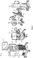
FIG. 1 is a schematic illustration of a surgical robotic system including a control tower, a console, and one or more surgical robotic arms according to an embodiment of the present disclosure; -
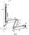
FIG. 2 is a perspective view of a surgical robotic arm of the surgical robotic system ofFIG. 1 according to an embodiment of the present disclosure; -
FIG. 3 is a perspective view of a setup arm with the surgical robotic arm of the surgical robotic system ofFIG. 1 according to an embodiment of the present disclosure; -
FIG. 4 is a schematic diagram of a computer architecture of the surgical robotic system ofFIG. 1 according to an embodiment of the present disclosure; -
FIG. 5 is a cross-sectional view of an actuator of the surgical robotic arm ofFIG. 2 according to the present disclosure; -
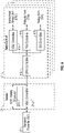
FIG. 6 is a schematic safety observer system according to the present disclosure; -
FIG. 7 is a flow chart of an algorithm implemented in a safety observer according to the present disclosure; and -
FIG. 8 is a flow chart of a method for detecting failure of an integrated joint module according to the present disclosure. - The term "application" may include a computer program designed to perform functions, tasks, or activities for the benefit of a user. Application may refer to, for example, software running locally or remotely, as a standalone program or in a web browser, or other software which would be understood by one skilled in the art to be an application. An application may run on a controller, or on a user device, including, for example, a mobile device, a personal computer, or a server system.
- As will be described in detail below, the present disclosure is directed to a surgical robotic system, which includes a surgical console, a control tower, and one or more movable carts having a surgical robotic arm coupled to a setup arm. The surgical console receives user input through one or more interface devices, which are interpreted by the control tower as movement commands for moving the surgical robotic arm. The surgical robotic arm includes a controller, which is configured to process the movement command and to generate a torque command for activating one or more actuators of the robotic arm, which would, in turn, move the robotic arm in response to the movement command.
- With reference to
FIG. 1 , a surgicalrobotic system 10 includes acontrol tower 20, which is connected to all of the components of the surgicalrobotic system 10 including asurgical console 30 and one or morerobotic arms 40. Each of therobotic arms 40 includes asurgical instrument 50 removably coupled thereto. Each of therobotic arms 40 is also coupled to amovable cart 60. - The
surgical instrument 50 is configured for use during minimally invasive surgical procedures. In embodiments, thesurgical instrument 50 may be configured for open surgical procedures. In embodiments, thesurgical instrument 50 may be an endoscope, such as an endoscopic camera 51, configured to provide a video feed for the user. In further embodiments, thesurgical instrument 50 may be an electrosurgical forceps configured to seal tissue by compressing tissue between jaw members and applying electrosurgical current thereto. In yet further embodiments, thesurgical instrument 50 may be a surgical stapler including a pair of jaws configured to grasp and clamp tissue while deploying a plurality of tissue fasteners, e.g., staples, and cutting stapled tissue. - One of the
robotic arms 40 may include the endoscopic camera 51 configured to capture video of the surgical site. The endoscopic camera 51 may be a stereoscopic endoscope configured to capture two side-by-side (i.e., left and right) images of the surgical site to produce a video stream of the surgical scene. The endoscopic camera 51 is coupled to avideo processing device 56, which may be disposed within thecontrol tower 20. Thevideo processing device 56 may be any computing device as described below configured to receive the video feed from the endoscopic camera 51 perform the image processing based on the depth estimating algorithms of the present disclosure and output the processed video stream. - The
surgical console 30 includes afirst display 32, which displays a video feed of the surgical site provided by camera 51 of thesurgical instrument 50 disposed on therobotic arms 40, and asecond display 34, which displays a user interface for controlling the surgicalrobotic system 10. The first andsecond displays - The
surgical console 30 also includes a plurality of user interface devices, such asfoot pedals 36 and a pair ofhandle controllers 38a and 38b which are used by a user to remotely controlrobotic arms 40. The surgical console further includes an armrest 33 used to support clinician's arms while operating thehandle controllers 38a and 38b. - The
control tower 20 includes adisplay 23, which may be a touchscreen, and outputs on the graphical user interfaces (GUIs). Thecontrol tower 20 also acts as an interface between thesurgical console 30 and one or morerobotic arms 40. In particular, thecontrol tower 20 is configured to control therobotic arms 40, such as to move therobotic arms 40 and the correspondingsurgical instrument 50, based on a set of programmable instructions and/or input commands from thesurgical console 30, in such a way thatrobotic arms 40 and thesurgical instrument 50 execute a desired movement sequence in response to input from thefoot pedals 36 and thehandle controllers 38a and 38b. - Each of the
control tower 20, thesurgical console 30, and therobotic arm 40 includes arespective computer computers - The
computers - With reference to
FIG. 2 , each of therobotic arms 40 may include a plurality oflinks joints robotic arm 40 to themovable cart 60 and defines a first longitudinal axis. With reference toFIG. 3 , themovable cart 60 includes alift 61 and asetup arm 62, which provides a base for mounting of therobotic arm 40. Thelift 61 allows for vertical movement of thesetup arm 62. Themovable cart 60 also includes adisplay 69 for displaying information pertaining to therobotic arm 40. - The
setup arm 62 includes afirst link 62a, a second link 62b, and a third link 62c, which provide for lateral maneuverability of therobotic arm 40. Thelinks 62a, 62b, 62c are interconnected atjoints 63a and 63b, each of which may include an actuator (not shown) for rotating the links 62b and 62b relative to each other and the link 62c. In particular, thelinks 62a, 62b, 62c are movable in their corresponding lateral planes that are parallel to each other, thereby allowing for extension of therobotic arm 40 relative to the patient (e.g., surgical table). In embodiments, therobotic arm 40 may be coupled to the surgical table (not shown). Thesetup arm 62 includescontrols 65 for adjusting movement of thelinks 62a, 62b, 62c as well as thelift 61. - The third link 62c includes a
rotatable base 64 having two degrees of freedom. In particular, therotatable base 64 includes afirst actuator 64a and asecond actuator 64b. Thefirst actuator 64a is rotatable about a first stationary arm axis which is perpendicular to a plane defined by the third link 62c and thesecond actuator 64b is rotatable about a second stationary arm axis which is transverse to the first stationary arm axis. The first andsecond actuators robotic arm 40. - The actuator 48b of the joint 44b is coupled to the joint 44c via the
belt 45a, and the joint 44c is in turn coupled to the joint 46c via thebelt 45b. Joint 44c may include a transfer case coupling thebelts actuator 48b is configured to rotate each of thelinks holder 46 relative to each other. More specifically,links holder 46 are passively coupled to theactuator 48b which enforces rotation about a pivot point "P" which lies at an intersection of the first axis defined by thelink 42a and the second axis defined by theholder 46. Thus, theactuator 48b controls the angle θ between the first and second axes allowing for orientation of thesurgical instrument 50. Due to the interlinking of thelinks holder 46 via thebelts links holder 46 are also adjusted in order to achieve the desired angle θ. In embodiments, some or all of thejoints - The
joints actuator joints belts actuator 48a is configured to rotate therobotic arm 40 about a longitudinal axis defined by thelink 42a. - With reference to
FIG. 2 , therobotic arm 40 also includes aholder 46 defining a second longitudinal axis and configured to receive an instrument drive unit (IDU) 52 (FIG. 1 ). TheIDU 52 is configured to couple to an actuation mechanism of thesurgical instrument 50 and the camera 51 and is configured to move (e.g., rotate) and actuate theinstrument 50 and/or the camera 51.IDU 52 transfers actuation forces from its actuators to thesurgical instrument 50 to actuate components (e.g., end effector) of thesurgical instrument 50. Theholder 46 includes a slidingmechanism 46a, which is configured to move theIDU 52 along the second longitudinal axis defined by theholder 46. Theholder 46 also includes a joint 46b, which rotates theholder 46 relative to thelink 42c. During endoscopic procedures, theinstrument 50 may be inserted through an endoscopic port 55 (FIG. 3 ) held by theholder 46. - The
robotic arm 40 also includes a plurality of manual override buttons 53 (FIGS. 1 and5 ) disposed on theIDU 52 and thesetup arm 62, which may be used in a manual mode. The user may press one or more of the buttons 53 to move the component associated with the button 53. - With reference to
FIG. 4 , each of thecomputers robotic system 10 may include a plurality of controllers, which may be embodied in hardware and/or software. Thecomputer 21 of thecontrol tower 20 includes amain controller 21a and asafety observer 21b. Thecontroller 21a receives data from thecomputer 31 of thesurgical console 30 about the current position and/or orientation of thehandle controllers 38a and 38b and the state of thefoot pedals 36 and other buttons. Thecontroller 21a processes these input positions to determine desired drive commands for each joint of therobotic arm 40 and/or theIDU 52 and communicates these to thecomputer 41 of therobotic arm 40. Thecontroller 21a also receives the actual joint angles measured by encoders of theactuators computer 31 of thesurgical console 30 to provide haptic feedback through thehandle controllers 38a and 38b. Thesafety observer 21b performs validity checks on the data going into and out of thecontroller 21a and notifies a system fault handler if errors in the data transmission are detected to place thecomputer 21 and/or the surgicalrobotic system 10 into a safe state. In embodiments, thesafety observer 21b may be embodied as software executable by thecontroller 21a rather than being a separate controller. - The
computer 41 includes a plurality of controllers, namely, amain cart controller 41a, asetup arm controller 41b, arobotic arm controller 41c, and an instrument drive unit (IDU)controller 41d. Themain cart controller 41a receives and processes joint commands from thecontroller 21a of thecomputer 21 and communicates them to thesetup arm controller 41b, therobotic arm controller 41c, and theIDU controller 41d. Themain cart controller 41a also manages instrument exchanges and the overall state of themovable cart 60, therobotic arm 40, and theIDU 52. Themain cart controller 41a also communicates actual joint angles back to thecontroller 21a. - The
setup arm controller 41b controls each ofjoints 63a and 63b, and therotatable base 64 of thesetup arm 62 and calculates desired motor movement commands (e.g., motor torque) for the pitch axis and controls the brakes. Therobotic arm controller 41c controls each joint 44a and 44b of therobotic arm 40 and calculates desired motor torques required for gravity compensation, friction compensation, and closed loop position control of therobotic arm 40. Therobotic arm controller 41c calculates a movement command based on the calculated torque. The calculated motor commands are then communicated to one or more of theactuators robotic arm 40. The actual joint positions are then transmitted by theactuators robotic arm controller 41c. - The
IDU controller 41d receives desired joint angles for thesurgical instrument 50, such as wrist and jaw angles, and computes desired currents for the motors in theIDU 52. TheIDU controller 41d calculates actual angles based on the motor positions and transmits the actual angles back to themain cart controller 41a. - The
robotic arm 40 is controlled in response to a pose of the handle controller controlling therobotic arm 40, e.g., thehandle controller 38a, which is transformed into a desired pose of therobotic arm 40 through a hand eye transform function executed by thecontroller 21a. The hand eye function, as well as other functions are embodied in software executable by thecontroller 21a or any other suitable controller described herein. The pose of one of thehandle controller 38a may be embodied as a coordinate position and role-pitch-yaw ("RPY") orientation relative to a coordinate reference frame, which is fixed to thesurgical console 30. The desired pose of theinstrument 50 is relative to a fixed frame on therobotic arm 40. The pose of thehandle controller 38a is then scaled by a scaling function executed by thecontroller 21a. In embodiments, the coordinate position is scaled down and the orientation is scaled up by the scaling function. In addition, thecontroller 21a also executes a clutching function, which disengages thehandle controller 38a from therobotic arm 40. In particular, thecontroller 21a stops transmitting movement commands from thehandle controller 38a to therobotic arm 40 if certain movement limits or other thresholds are exceeded and in essence acts like a virtual clutch mechanism, e.g., limits mechanical input from effecting mechanical output. - The desired pose of the
robotic arm 40 is based on the pose of thehandle controller 38a and is then passed by an inverse kinematics function executed by thecontroller 21a. The inverse kinematics function calculates angles for thejoints robotic arm 40 that achieve the scaled and adjusted pose input by thehandle controller 38a. The calculated angles are then passed to therobotic arm controller 41c, which includes a joint axis controller having a proportional-derivative (PD) controller, the friction estimator module, the gravity compensator module, and a two-sided saturation block, which is configured to limit the commanded torque of the motors of thejoints - The
robotic arm controller 41c is also configured to estimate torque imparted on thejoints robotic arm 40, namely, thelinks joints robotic arm 40 due to the heavy weight of therobotic arm 40. However, the torque may need to be adjusted to prevent damage or injury. This is particularly useful for limiting torque during collisions of therobotic arm 40 with external objects, such as other robotic arms, patient, staff, operating room equipment, etc. - In order to determine the effect of external torque on the
robotic arm 40 therobotic arm controller 41c initially calculates frictional losses, gravitational forces, inertia, and then determines the effects of external torque. Once the external torque is calculated, therobotic arm controller 41c determines whether the environmental forces exceed a predetermined threshold which is indicative of collisions with external objects and takes precautionary action, such as terminating movement in the direction in which collision was detected, slowing down, and/or reversing movement (e.g., moving in an opposite direction) for a predetermined distance. - The sensor measurements and calculations based thereon are described below with respect to
FIG. 5 , which shows an integratedjoint module 100. The integratedjoint module 100 may be used as theactuators joints 63a and 63b. The integratedjoint module 100 includes ashaft 102, which acts as a support structure for the other components of the integratedjoint module 100, namely, amotor 104 and aharmonic gearbox 106. Themotor 104 may be any electric motor, which may be powered by AC or DC energy, such as a brushed motor, a brushless motor, a stepper motor, and the like. Themotor 104 is coupled to theharmonic gearbox 106, which may be a harmonic drive gear configured to provide a large reduction ratio with approximately zero backlash, high torque capability, and high efficiency. Theharmonic gearbox 106 may include concentric input and output shafts (not shown) and may include awave generator 106a, disposed within aflexspline 106b having an outer geared surface, which is in turn, disposed within acircular spline 106c having an inner geared surface. As themotor 104 drives thewave generator 106a, theflexspline 106b, which may be formed from an elastic material, such as stainless steel, is also rotated. Theflexspline 106b has fewer teeth than thecircular spline 106c, therefore for every full rotation of thewave generator 106a, theflexspline 106b rotates less than a full rotation, which reduces the output speed. Theharmonic gearbox 106 is in turn coupled to one of thebelts - The integrated
joint module 100 also includes a sensor suite for monitoring the performance of the integratedjoint module 100 to provide for feedback and control thereof. In particular, the integratedjoint module 100 includes anencoder 108 coupled to themotor 104. Theencoder 108 may be any device that provides a sensor signal indicative of the number of rotations of themotor 104, such as a mechanical encoder or an optical encoder. Themotor 104 may also include other sensors, such as a current sensor configured to measure the current draw of themotor 104, amotor torque sensor 105 for measuring motor torque, and the like. The number of rotations may be used to determine the speed and/or position control ofindividual joints encoder 108 may include speed, distance, revolutions per minute, position, and the like. The integratedjoint module 100 further includes ajoint torque sensor 110 may be any force or strain sensor including one or more strain gauges configured to convert mechanical forces and/or strain into a sensor signal indicative of the torque imparted by theharmonic gearbox 106. The sensor signals from theencoder 108 and thejoint torque sensor 110 are transmitted to thecomputer 41, which then controls the speed, angle, and/or position of each of thejoints robotic arm 40 based on the sensor signals. In embodiments, additional position sensors may also be used to determine movement and orientation of therobotic arm 40 and thesetup arm 62. Suitable sensors include, but are not limited to, potentiometers coupled to movable components and configured to detect travel distances, Hall Effect sensors, accelerometers, and gyroscopes. - With reference to
FIG. 6 , thesafety observer 21b is shown as processing sensor signals from the integratedjoint module 100. The integratedjoint module 100 outputs sensor signals from electronic components 201 (e.g., current sensor) and mechanical components 202 (e.g., themotor torque sensor 105, thejoint torque sensor 110, theencoder 108, etc.). Sensor signals are shown as anoutput 200a. Theoutput 200a is provided over a wired (e.g., ETHERCAT® or any other Ethernet-based fieldbus system) or a wireless connection to thecontroller 21a. Thecontroller 21a utilizes theoutput 200a to control the integratedjoint module 100 as described above, e.g., transmitting drive commands to the integratedjoint module 100, which in turn, achieves the commanded pose. The drive commands are shown as aninput 200b. - The
safety observer 21b compares theoutput 200a and theinput 200b to determine if there is a failure, which includes a failure in communication,electronic components 201, mechanical components 202 (e.g., error in the torque sensor readings), the motor 104 (e.g., error in the applied torque), etc. - According to one embodiment, the
safety observer 21b is configured to determine a failure by calculating a total torque error based on a difference between joint torque sensor measurement from thejoint torque sensor 110 and commanded motor torque, which is based on the drive command from thecontroller 21a. - According to another embodiment, the
safety observer 21b is configured to determine a failure by estimating velocity of themotor 104 from a drive train simulation. The estimated velocity is then compared with actual velocity of themotor 104 as measured by theencoder 108. The drive train model may be represented by formula (1) below:
- where τm,d is the commanded motor torque based on actuator input and may be measured based on the magnetic field generated by the
motor 104, τm , is the measured motor torque which is based on actuator output, b is inertia of themotor 104 and theharmonic gearbox 106, θ̈ is the acceleration, τfric is the friction of themotor 104 and theharmonic gearbox 106, and τj is the joint torque based on actuator output and is measured using thejoint torque sensor 110 representative of the mechanical strain. The observer may be implemented with τm,d or τm. - In addition, τfric , the friction of the
motor 104 and theharmonic gearbox 106 may be represented by formula (2) below:
- Thus, τfric is a sum of Coulomb friction, represented as, (fc + fl |τj |)sign(θ̇) which is based on direction of motion and is load dependent, and fvθ̇, is a viscous friction, which is velocity dependent.
- Based on the above formulas, the observer model is based on the drive train model but incorporates sensor errors into the formulas. Thus, the observer model may be represented by formula (3) below and the individual errors in formulas (4)-(6):


- Thus, τerror is a difference between joint torque error, τs,error, and actuator input error, τm,error. The observer model may be used to determine the observed (i.e., estimated) velocity using formula (7):

- As shown in
FIG. 7 , which shows a flow chart of a method for determining velocity error, the velocity error is determined based on a difference of actual velocity and observed velocity (determined using the observer model). In particular, the velocity observer calculates observed velocity based on τm,d and τsm. The velocity error may then also be compared to a range of velocity error limits to determine if the error is sufficient to issue an alarm and/or stop operation. - The present disclosure also provides for modifying the observer model implemented in the
safety observer 21b to increase its bandwidth. In particular, the dynamics of the observer model are limited or equal to the drive train model, which is relatively slow, especially when viewed in the context of requirements for detecting velocity errors. Thus, the observer model may be updated to increase dynamics by reducing sensitivity to variation of mechanical viscous friction. This may be accomplished by accounting for kinetic friction, fkθ̇, which is added to both sides of the observer model as shown in formula (8), which is based on formula (3) above.
- Similarly, observed velocity may be calculated using formula (9) below, which is based on formula (7) above:

- The method for detecting failures in the applied torque of the
joint module 100 is described with reference toFIG. 8 . A movement command from thehandle controller 38a is output as a specific drive command by thecontroller 21a to the integratedjoint module 100. The drive command instructs themotor 104 to output a specific torque to achieve the commanded movement. As themotor 104 is actuated, various sensors, e.g., current sensor, themotor torque sensor 105, thejoint torque sensor 110, theencoder 108, etc. provide feedback including current, motor torque, sensor torque, and motor speed, to thecontroller 21a and thesafety observer 21b. In particular, thesafety observer 21b receives measured velocity of themotor 104. - The
safety observer 21b also calculates observed velocity as described above, based on error-adjusted motor torque τm,d and error-adjusted joint torque τs (seeFIG. 7 ). Thesafety observer 21b also calculates a difference between measured velocity and observed velocity. The difference is then compared to a range limit as shown in formula (10):
- The positive and negative θ̇limit values represent error amounts indicative of a mismatch between measured and observed velocities due to a failure in applied torque of the integrated
joint module 100 and/or torque sensor readings. Thus, if the velocity error is within the limit, the integratedjoint module 100 may continue to operate. However, if the velocity error is outside the limit, thesafety observer 21b outputs an error to thecontroller 21a which may handle the error according to any prescribed method, such as stop operation of therobotic arm 40 and/or output error on displays, etc. - It will be understood that various modifications may be made to the embodiments disclosed herein. In embodiments, the sensors may be disposed on any suitable portion of the robotic arm. Therefore, the above description should not be construed as limiting, but merely as exemplifications of various embodiments. Those skilled in the art will envision other modifications within the scope and spirit of the claims appended thereto.
- The invention may be described by reference to the following numbered paragraphs:-
- 1. A surgical robotic system comprising:
- a robotic arm including at least one joint having a motor and at least one sensor;
- a main controller configured to output a drive command to the motor to actuate the motor; and
- a safety observer configured to:
- receive a measured velocity of the motor from the at least one sensor;
- calculate an observed velocity of the motor; and
- detect a failure in operation of the at least one joint based on the observed velocity and the measured velocity.
- 2. The surgical robotic system according to paragraph 1, wherein the safety observer is further configured to output an error to the main controller in response to detection of the failure.
- 3. The surgical robotic system according to paragraph 1, wherein the at least one sensor includes a joint torque sensor configured to measure joint torque of the at least one joint.
- 4. The surgical robotic system according to paragraph 3, wherein the at least one sensor further includes at least one motor sensor configured to determine a motor torque of the motor.
- 5. The surgical robotic system according to paragraph 4, wherein the safety observer is further configured to calculate the observed velocity based on the joint torque and the motor torque.
- 6. The surgical robotic system according to paragraph 5, wherein the safety observer is further configured to:
- calculate a velocity difference between the observed velocity and the measured velocity; and
- compare the velocity difference to a velocity error range.
- 7. The surgical robotic system according to paragraph 6, wherein the safety observer is further configured to detect the failure in response to the velocity difference being outside the velocity error range.
- 8. The surgical robotic system according to paragraph 3, wherein the safety observer is further configured to calculate the observed velocity based on the joint torque and commanded motor torque of the drive command.
- 9. A surgical robotic system comprising:
- a robotic arm including at least one joint having a motor and at least one torque sensor and a velocity sensor;
- a main controller configured to output a drive command to the motor to actuate the motor; and
- a safety observer configured to:
- receive a measured velocity of the motor from the velocity sensor and at least one torque measurement from the at least one torque sensor;
- calculate an observed velocity of the motor based on the at least one torque measurement; and
- detect a failure in operation of the at least one joint based on the observed velocity and the measured velocity.
- 10. The surgical robotic system according to paragraph 9, wherein the safety observer is further configured to output an error to the main controller in response to detection of the failure.
- 11. The surgical robotic system according to paragraph 9, wherein the at least one torque sensor includes a joint torque sensor configured to measure joint torque of the at least one joint.
- 12. The surgical robotic system according to paragraph 11, wherein the at least one sensor further includes at least one motor sensor configured to measure a motor torque of the motor.
- 13. The surgical robotic system according to paragraph 12, wherein the safety observer is further configured to calculate the observed velocity based on the joint torque and the motor torque.
- 14. The surgical robotic system according to paragraph 13, wherein the safety observer is further configured to:
- calculate a velocity difference between the observed velocity and the measured velocity; and
- compare the velocity difference to a velocity error range.
- 15. The surgical robotic system according to paragraph 14, wherein the safety observer is further configured to detect the failure in response to the velocity difference being outside the velocity error range.
- 16. The surgical robotic system according to paragraph 11, wherein the safety observer is further configured to calculate the observed velocity based on the joint torque and commanded motor torque of the drive command.
- 17. A method for controlling a surgical robot, the method comprising:
- outputting a drive command at a main controller to a motor of at least one joint of a robotic arm to actuate the motor;
- measuring velocity of the motor using at least one sensor;
- receiving at a safety observer a measured velocity from the at least one sensor;
- calculating at the safety observer an observed velocity; and
- detecting at a safety observer a failure in operation of the at least one joint based on the observed velocity and the measured velocity.
- 18. The method according to paragraph 17, further comprising:
- measuring joint torque of the at least one joint at a joint torque sensor; and
- measuring motor torque of the motor through at least one motor sensor.
- 19. The method according to paragraph 18, further comprising:
- calculating the observed velocity based on the joint torque and the motor torque; and
- calculating a velocity difference between the observed velocity and the measured velocity.
- 20. The method according to paragraph 19, further comprising:
- comparing the velocity difference to a velocity error range; and
- detecting the failure in response to the velocity difference being outside the velocity error range.
Claims (15)
- A surgical robotic system comprising:a robotic arm including at least one joint having a motor and at least one sensor;a main controller configured to output a drive command to the motor to actuate the motor; anda safety observer configured to:receive a measured velocity of the motor from the at least one sensor;calculate an observed velocity of the motor; anddetect a failure in operation of the at least one joint based on the observed velocity and the measured velocity.
- The surgical robotic system according to claim 1, wherein the safety observer is further configured to output an error to the main controller in response to detection of the failure.
- The surgical robotic system according to claim 1 or claim 2, wherein the at least one sensor includes a joint torque sensor configured to measure joint torque of the at least one joint; preferably wherein the at least one sensor further includes at least one motor sensor configured to determine a motor torque of the motor.
- The surgical robotic system according to claim 3, wherein the safety observer is further configured to calculate the observed velocity based on the joint torque and the motor torque; preferably wherein the safety observer is further configured to:calculate a velocity difference between the observed velocity and the measured velocity; andcompare the velocity difference to a velocity error range.
- The surgical robotic system according to claim 4, wherein the safety observer is further configured to detect the failure in response to the velocity difference being outside the velocity error range.
- The surgical robotic system according to claim 3, wherein the safety observer is further configured to calculate the observed velocity based on the joint torque and commanded motor torque of the drive command.
- A surgical robotic system comprising:a robotic arm including at least one joint having a motor and at least one torque sensor and a velocity sensor;a main controller configured to output a drive command to the motor to actuate the motor; anda safety observer configured to:receive a measured velocity of the motor from the velocity sensor and at least one torque measurement from the at least one torque sensor;calculate an observed velocity of the motor based on the at least one torque measurement; anddetect a failure in operation of the at least one joint based on the observed velocity and the measured velocity.
- The surgical robotic system according to claim 7, wherein the safety observer is further configured to output an error to the main controller in response to detection of the failure; and/or wherein the at least one torque sensor includes a joint torque sensor configured to measure joint torque of the at least one joint.
- The surgical robotic system according to claim 7 or claim 8, wherein the at least one sensor further includes at least one motor sensor configured to measure a motor torque of the motor.
- The surgical robotic system according to any of claims 7 to 9 wherein the safety observer is further configured to calculate the observed velocity based on the joint torque and the motor torque.
- The surgical robotic system according to claim 10, wherein the safety observer is further configured to:calculate a velocity difference between the observed velocity and the measured velocity; andcompare the velocity difference to a velocity error range.
- The surgical robotic system according to claim 11, wherein the safety observer is further configured to detect the failure in response to the velocity difference being outside the velocity error range.
- The surgical robotic system according to any of claims 7 to 12, wherein the safety observer is further configured to calculate the observed velocity based on the joint torque and commanded motor torque of the drive command.
- A method for controlling a surgical robot, the method comprising:outputting a drive command at a main controller to a motor of at least one joint of a robotic arm to actuate the motor;measuring velocity of the motor using at least one sensor;receiving at a safety observer a measured velocity from the at least one sensor;calculating at the safety observer an observed velocity; anddetecting at a safety observer a failure in operation of the at least one joint based on the observed velocity and the measured velocity; preferably further comprising:measuring joint torque of the at least one joint at a joint torque sensor; andmeasuring motor torque of the motor through at least one motor sensor.
- The method according to claim 14, further comprising:calculating the observed velocity based on the joint torque and the motor torque; andcalculating a velocity difference between the observed velocity and the measured velocity; preferably further comprising:comparing the velocity difference to a velocity error range; anddetecting the failure in response to the velocity difference being outside the velocity error range.
Applications Claiming Priority (2)
| Application Number | Priority Date | Filing Date | Title |
|---|---|---|---|
| US202163194270P | 2021-05-28 | 2021-05-28 | |
| US17/737,256 US12369998B2 (en) | 2021-05-28 | 2022-05-05 | Real time monitoring of a robotic drive module |
Publications (1)
| Publication Number | Publication Date |
|---|---|
| EP4094713A1 true EP4094713A1 (en) | 2022-11-30 |
Family
ID=81851700
Family Applications (1)
| Application Number | Title | Priority Date | Filing Date |
|---|---|---|---|
| EP22175901.2A Pending EP4094713A1 (en) | 2021-05-28 | 2022-05-27 | Real time monitoring of a robotic drive module |
Country Status (3)
| Country | Link |
|---|---|
| US (2) | US12369998B2 (en) |
| EP (1) | EP4094713A1 (en) |
| CN (1) | CN115399884A (en) |
Cited By (1)
| Publication number | Priority date | Publication date | Assignee | Title |
|---|---|---|---|---|
| CN116279890A (en) * | 2023-03-20 | 2023-06-23 | 大连理工大学 | Two-wheel leg end logistics distribution robot |
Families Citing this family (3)
| Publication number | Priority date | Publication date | Assignee | Title |
|---|---|---|---|---|
| US12369998B2 (en) * | 2021-05-28 | 2025-07-29 | Covidien Lp | Real time monitoring of a robotic drive module |
| CA3263629A1 (en) * | 2022-08-30 | 2024-03-07 | Alcon Inc. | Contact management mode for robotic imaging system using multiple sensors |
| US12496160B2 (en) * | 2022-09-14 | 2025-12-16 | Auris Health, Inc. | Anomaly detection in instruments in a surgical robotic system |
Citations (5)
| Publication number | Priority date | Publication date | Assignee | Title |
|---|---|---|---|---|
| US4807153A (en) * | 1986-11-20 | 1989-02-21 | Unimation Inc. | Multiaxis digital robot control having a backup velocity monitor and protection system |
| US20140121832A1 (en) * | 2010-07-12 | 2014-05-01 | Seiko Epson Corporation | Robotic device and method of controlling robotic device |
| EP3120979A1 (en) * | 2014-03-14 | 2017-01-25 | Sony Corporation | Robot arm device, robot arm control method and program |
| US20190091861A1 (en) * | 2016-03-29 | 2019-03-28 | Sony Corporation | Control apparatus and control method |
| WO2020246997A1 (en) * | 2019-06-03 | 2020-12-10 | Covidien Lp | System and apparatus for external torque observation and compensation for surgical robotic arm |
Family Cites Families (228)
| Publication number | Priority date | Publication date | Assignee | Title |
|---|---|---|---|---|
| US5762458A (en) | 1996-02-20 | 1998-06-09 | Computer Motion, Inc. | Method and apparatus for performing minimally invasive cardiac procedures |
| US5855583A (en) | 1996-02-20 | 1999-01-05 | Computer Motion, Inc. | Method and apparatus for performing minimally invasive cardiac procedures |
| US5792135A (en) | 1996-05-20 | 1998-08-11 | Intuitive Surgical, Inc. | Articulated surgical instrument for performing minimally invasive surgery with enhanced dexterity and sensitivity |
| US6364888B1 (en) | 1996-09-09 | 2002-04-02 | Intuitive Surgical, Inc. | Alignment of master and slave in a minimally invasive surgical apparatus |
| US6331181B1 (en) | 1998-12-08 | 2001-12-18 | Intuitive Surgical, Inc. | Surgical robotic tools, data architecture, and use |
| US8206406B2 (en) | 1996-12-12 | 2012-06-26 | Intuitive Surgical Operations, Inc. | Disposable sterile surgical adaptor |
| US6132368A (en) | 1996-12-12 | 2000-10-17 | Intuitive Surgical, Inc. | Multi-component telepresence system and method |
| US7666191B2 (en) | 1996-12-12 | 2010-02-23 | Intuitive Surgical, Inc. | Robotic surgical system with sterile surgical adaptor |
| US8182469B2 (en) | 1997-11-21 | 2012-05-22 | Intuitive Surgical Operations, Inc. | Surgical accessory clamp and method |
| US8529582B2 (en) | 1996-12-12 | 2013-09-10 | Intuitive Surgical Operations, Inc. | Instrument interface of a robotic surgical system |
| US7727244B2 (en) | 1997-11-21 | 2010-06-01 | Intuitive Surgical Operation, Inc. | Sterile surgical drape |
| US7699855B2 (en) | 1996-12-12 | 2010-04-20 | Intuitive Surgical Operations, Inc. | Sterile surgical adaptor |
| US6714839B2 (en) | 1998-12-08 | 2004-03-30 | Intuitive Surgical, Inc. | Master having redundant degrees of freedom |
| DE69940850D1 (en) | 1998-08-04 | 2009-06-18 | Intuitive Surgical Inc | Articular device for positioning a manipulator for robotic surgery |
| US6951535B2 (en) | 2002-01-16 | 2005-10-04 | Intuitive Surgical, Inc. | Tele-medicine system that transmits an entire state of a subsystem |
| US8600551B2 (en) | 1998-11-20 | 2013-12-03 | Intuitive Surgical Operations, Inc. | Medical robotic system with operatively couplable simulator unit for surgeon training |
| US6659939B2 (en) | 1998-11-20 | 2003-12-09 | Intuitive Surgical, Inc. | Cooperative minimally invasive telesurgical system |
| US6459926B1 (en) | 1998-11-20 | 2002-10-01 | Intuitive Surgical, Inc. | Repositioning and reorientation of master/slave relationship in minimally invasive telesurgery |
| US7125403B2 (en) | 1998-12-08 | 2006-10-24 | Intuitive Surgical | In vivo accessories for minimally invasive robotic surgery |
| US6770081B1 (en) | 2000-01-07 | 2004-08-03 | Intuitive Surgical, Inc. | In vivo accessories for minimally invasive robotic surgery and methods |
| US6493608B1 (en) | 1999-04-07 | 2002-12-10 | Intuitive Surgical, Inc. | Aspects of a control system of a minimally invasive surgical apparatus |
| US6799065B1 (en) | 1998-12-08 | 2004-09-28 | Intuitive Surgical, Inc. | Image shifting apparatus and method for a telerobotic system |
| US6394998B1 (en) | 1999-01-22 | 2002-05-28 | Intuitive Surgical, Inc. | Surgical tools for use in minimally invasive telesurgical applications |
| US6424885B1 (en) | 1999-04-07 | 2002-07-23 | Intuitive Surgical, Inc. | Camera referenced control in a minimally invasive surgical apparatus |
| US6565554B1 (en) | 1999-04-07 | 2003-05-20 | Intuitive Surgical, Inc. | Friction compensation in a minimally invasive surgical apparatus |
| US8944070B2 (en) | 1999-04-07 | 2015-02-03 | Intuitive Surgical Operations, Inc. | Non-force reflecting method for providing tool force information to a user of a telesurgical system |
| US6594552B1 (en) | 1999-04-07 | 2003-07-15 | Intuitive Surgical, Inc. | Grip strength with tactile feedback for robotic surgery |
| US7695485B2 (en) | 2001-11-30 | 2010-04-13 | Power Medical Interventions, Llc | Surgical device |
| US6793652B1 (en) | 1999-06-02 | 2004-09-21 | Power Medical Interventions, Inc. | Electro-mechanical surgical device |
| US6716233B1 (en) | 1999-06-02 | 2004-04-06 | Power Medical Interventions, Inc. | Electromechanical driver and remote surgical instrument attachment having computer assisted control capabilities |
| US6315184B1 (en) | 1999-06-02 | 2001-11-13 | Powermed, Inc. | Stapling device for use with an electromechanical driver device for use with anastomosing, stapling, and resecting instruments |
| US8004229B2 (en) | 2005-05-19 | 2011-08-23 | Intuitive Surgical Operations, Inc. | Software center and highly configurable robotic systems for surgery and other uses |
| US10188471B2 (en) | 1999-09-17 | 2019-01-29 | Intuitive Surgical Operations, Inc. | Tele-operative surgical systems and methods of control at joint limits using inverse kinematics |
| US8768516B2 (en) | 2009-06-30 | 2014-07-01 | Intuitive Surgical Operations, Inc. | Control of medical robotic system manipulator about kinematic singularities |
| US7594912B2 (en) | 2004-09-30 | 2009-09-29 | Intuitive Surgical, Inc. | Offset remote center manipulator for robotic surgery |
| US9259280B2 (en) | 1999-09-17 | 2016-02-16 | Intuitive Surgical Operations, Inc. | Phantom degrees of freedom in joint estimation and control |
| US6206903B1 (en) | 1999-10-08 | 2001-03-27 | Intuitive Surgical, Inc. | Surgical tool with mechanical advantage |
| US6312435B1 (en) | 1999-10-08 | 2001-11-06 | Intuitive Surgical, Inc. | Surgical instrument with extended reach for use in minimally invasive surgery |
| US6491691B1 (en) | 1999-10-08 | 2002-12-10 | Intuitive Surgical, Inc. | Minimally invasive surgical hook apparatus and method for using same |
| US7803151B2 (en) | 2001-12-04 | 2010-09-28 | Power Medical Interventions, Llc | System and method for calibrating a surgical instrument |
| US6645196B1 (en) | 2000-06-16 | 2003-11-11 | Intuitive Surgical, Inc. | Guided tool change |
| US6746443B1 (en) | 2000-07-27 | 2004-06-08 | Intuitive Surgical Inc. | Roll-pitch-roll surgical tool |
| US6902560B1 (en) | 2000-07-27 | 2005-06-07 | Intuitive Surgical, Inc. | Roll-pitch-roll surgical tool |
| US6840938B1 (en) | 2000-12-29 | 2005-01-11 | Intuitive Surgical, Inc. | Bipolar cauterizing instrument |
| US6783524B2 (en) | 2001-04-19 | 2004-08-31 | Intuitive Surgical, Inc. | Robotic surgical tool with ultrasound cauterizing and cutting instrument |
| US6994708B2 (en) | 2001-04-19 | 2006-02-07 | Intuitive Surgical | Robotic tool with monopolar electro-surgical scissors |
| US7824401B2 (en) | 2004-10-08 | 2010-11-02 | Intuitive Surgical Operations, Inc. | Robotic tool with wristed monopolar electrosurgical end effectors |
| US7607440B2 (en) | 2001-06-07 | 2009-10-27 | Intuitive Surgical, Inc. | Methods and apparatus for surgical planning |
| US6817974B2 (en) | 2001-06-29 | 2004-11-16 | Intuitive Surgical, Inc. | Surgical tool having positively positionable tendon-actuated multi-disk wrist joint |
| US6699235B2 (en) | 2001-06-29 | 2004-03-02 | Intuitive Surgical, Inc. | Platform link wrist mechanism |
| US6676684B1 (en) | 2001-09-04 | 2004-01-13 | Intuitive Surgical, Inc. | Roll-pitch-roll-yaw surgical tool |
| US6728599B2 (en) | 2001-09-07 | 2004-04-27 | Computer Motion, Inc. | Modularity system for computer assisted surgery |
| US6839612B2 (en) | 2001-12-07 | 2005-01-04 | Institute Surgical, Inc. | Microwrist system for surgical procedures |
| US6793653B2 (en) | 2001-12-08 | 2004-09-21 | Computer Motion, Inc. | Multifunctional handle for a medical robotic system |
| US7386365B2 (en) | 2004-05-04 | 2008-06-10 | Intuitive Surgical, Inc. | Tool grip calibration for robotic surgery |
| EP2359768B1 (en) | 2002-12-06 | 2018-10-03 | Intuitive Surgical Operations, Inc. | Flexible wrist for surgical tool |
| US8882657B2 (en) | 2003-03-07 | 2014-11-11 | Intuitive Surgical Operations, Inc. | Instrument having radio frequency identification systems and methods for use |
| US7410483B2 (en) | 2003-05-23 | 2008-08-12 | Novare Surgical Systems, Inc. | Hand-actuated device for remote manipulation of a grasping tool |
| US9002518B2 (en) | 2003-06-30 | 2015-04-07 | Intuitive Surgical Operations, Inc. | Maximum torque driving of robotic surgical tools in robotic surgical systems |
| US7379790B2 (en) | 2004-05-04 | 2008-05-27 | Intuitive Surgical, Inc. | Tool memory-based software upgrades for robotic surgery |
| US7947034B2 (en) | 2004-07-30 | 2011-05-24 | Tyco Healthcare Group Lp | Flexible shaft extender and method of using same |
| US9261172B2 (en) | 2004-09-30 | 2016-02-16 | Intuitive Surgical Operations, Inc. | Multi-ply strap drive trains for surgical robotic arms |
| US9700334B2 (en) | 2004-11-23 | 2017-07-11 | Intuitive Surgical Operations, Inc. | Articulating mechanisms and link systems with torque transmission in remote manipulation of instruments and tools |
| US8465474B2 (en) | 2009-05-19 | 2013-06-18 | Intuitive Surgical Operations, Inc. | Cleaning of a surgical instrument force sensor |
| US8496647B2 (en) | 2007-12-18 | 2013-07-30 | Intuitive Surgical Operations, Inc. | Ribbed force sensor |
| US8108072B2 (en) | 2007-09-30 | 2012-01-31 | Intuitive Surgical Operations, Inc. | Methods and systems for robotic instrument tool tracking with adaptive fusion of kinematics information and image information |
| US10555775B2 (en) | 2005-05-16 | 2020-02-11 | Intuitive Surgical Operations, Inc. | Methods and system for performing 3-D tool tracking by fusion of sensor and/or camera derived data during minimally invasive robotic surgery |
| US8147503B2 (en) | 2007-09-30 | 2012-04-03 | Intuitive Surgical Operations Inc. | Methods of locating and tracking robotic instruments in robotic surgical systems |
| US8398541B2 (en) | 2006-06-06 | 2013-03-19 | Intuitive Surgical Operations, Inc. | Interactive user interfaces for robotic minimally invasive surgical systems |
| US11259870B2 (en) | 2005-06-06 | 2022-03-01 | Intuitive Surgical Operations, Inc. | Interactive user interfaces for minimally invasive telesurgical systems |
| US8100133B2 (en) | 2005-06-30 | 2012-01-24 | Intuitive Surgical Operations | Indicator for tool state and communication in multi-arm robotic telesurgery and method of use |
| US8273076B2 (en) | 2005-06-30 | 2012-09-25 | Intuitive Surgical Operations, Inc. | Indicator for tool state and communication in multi-arm robotic telesurgery |
| US8079950B2 (en) | 2005-09-29 | 2011-12-20 | Intuitive Surgical Operations, Inc. | Autofocus and/or autoscaling in telesurgery |
| US8182470B2 (en) | 2005-12-20 | 2012-05-22 | Intuitive Surgical Operations, Inc. | Telescoping insertion axis of a robotic surgical system |
| US7819859B2 (en) | 2005-12-20 | 2010-10-26 | Intuitive Surgical Operations, Inc. | Control system for reducing internally generated frictional and inertial resistance to manual positioning of a surgical manipulator |
| US7741802B2 (en) * | 2005-12-20 | 2010-06-22 | Intuitive Surgical Operations, Inc. | Medical robotic system with programmably controlled constraints on error dynamics |
| US7762825B2 (en) | 2005-12-20 | 2010-07-27 | Intuitive Surgical Operations, Inc. | Electro-mechanical interfaces to mount robotic surgical arms |
| US7453227B2 (en) | 2005-12-20 | 2008-11-18 | Intuitive Surgical, Inc. | Medical robotic system with sliding mode control |
| US7689320B2 (en) | 2005-12-20 | 2010-03-30 | Intuitive Surgical Operations, Inc. | Robotic surgical system with joint motion controller adapted to reduce instrument tip vibrations |
| ATE547059T1 (en) | 2005-12-20 | 2012-03-15 | Intuitive Surgical Operations | INSTRUMENT INTERFACE OF A ROBOTIC SURGERY SYSTEM |
| US9241767B2 (en) | 2005-12-20 | 2016-01-26 | Intuitive Surgical Operations, Inc. | Method for handling an operator command exceeding a medical device state limitation in a medical robotic system |
| US7757028B2 (en) | 2005-12-22 | 2010-07-13 | Intuitive Surgical Operations, Inc. | Multi-priority messaging |
| US8054752B2 (en) | 2005-12-22 | 2011-11-08 | Intuitive Surgical Operations, Inc. | Synchronous data communication |
| US7756036B2 (en) | 2005-12-22 | 2010-07-13 | Intuitive Surgical Operations, Inc. | Synchronous data communication |
| US8628518B2 (en) | 2005-12-30 | 2014-01-14 | Intuitive Surgical Operations, Inc. | Wireless force sensor on a distal portion of a surgical instrument and method |
| US7930065B2 (en) | 2005-12-30 | 2011-04-19 | Intuitive Surgical Operations, Inc. | Robotic surgery system including position sensors using fiber bragg gratings |
| US7907166B2 (en) | 2005-12-30 | 2011-03-15 | Intuitive Surgical Operations, Inc. | Stereo telestration for robotic surgery |
| US7835823B2 (en) | 2006-01-05 | 2010-11-16 | Intuitive Surgical Operations, Inc. | Method for tracking and reporting usage events to determine when preventive maintenance is due for a medical robotic system |
| US8597182B2 (en) | 2006-04-28 | 2013-12-03 | Intuitive Surgical Operations, Inc. | Robotic endoscopic retractor for use in minimally invasive surgery |
| US8597280B2 (en) | 2006-06-13 | 2013-12-03 | Intuitive Surgical Operations, Inc. | Surgical instrument actuator |
| CN104688327B (en) | 2006-06-13 | 2017-06-09 | 直观外科手术操作公司 | Minimally Invasive Surgical System |
| US8419717B2 (en) | 2006-06-13 | 2013-04-16 | Intuitive Surgical Operations, Inc. | Control system configured to compensate for non-ideal actuator-to-joint linkage characteristics in a medical robotic system |
| US20090192523A1 (en) | 2006-06-29 | 2009-07-30 | Intuitive Surgical, Inc. | Synthetic representation of a surgical instrument |
| US9718190B2 (en) | 2006-06-29 | 2017-08-01 | Intuitive Surgical Operations, Inc. | Tool position and identification indicator displayed in a boundary area of a computer display screen |
| US10008017B2 (en) | 2006-06-29 | 2018-06-26 | Intuitive Surgical Operations, Inc. | Rendering tool information as graphic overlays on displayed images of tools |
| US7391173B2 (en) | 2006-06-30 | 2008-06-24 | Intuitive Surgical, Inc | Mechanically decoupled capstan drive |
| US8151661B2 (en) | 2006-06-30 | 2012-04-10 | Intuituve Surgical Operations, Inc. | Compact capstan |
| US7736254B2 (en) | 2006-10-12 | 2010-06-15 | Intuitive Surgical Operations, Inc. | Compact cable tension tender device |
| US7935130B2 (en) | 2006-11-16 | 2011-05-03 | Intuitive Surgical Operations, Inc. | Two-piece end-effectors for robotic surgical tools |
| US8758229B2 (en) | 2006-12-21 | 2014-06-24 | Intuitive Surgical Operations, Inc. | Axial visualization systems |
| EP1955830B1 (en) * | 2007-02-06 | 2014-04-09 | Abb Research Ltd. | A method and a control system for monitoring the condition of an industrial robot |
| US8620473B2 (en) | 2007-06-13 | 2013-12-31 | Intuitive Surgical Operations, Inc. | Medical robotic system with coupled control modes |
| US9084623B2 (en) | 2009-08-15 | 2015-07-21 | Intuitive Surgical Operations, Inc. | Controller assisted reconfiguration of an articulated instrument during movement into and out of an entry guide |
| US8903546B2 (en) | 2009-08-15 | 2014-12-02 | Intuitive Surgical Operations, Inc. | Smooth control of an articulated instrument across areas with different work space conditions |
| US9138129B2 (en) | 2007-06-13 | 2015-09-22 | Intuitive Surgical Operations, Inc. | Method and system for moving a plurality of articulated instruments in tandem back towards an entry guide |
| US9050120B2 (en) | 2007-09-30 | 2015-06-09 | Intuitive Surgical Operations, Inc. | Apparatus and method of user interface with alternate tool mode for robotic surgical tools |
| US8012170B2 (en) | 2009-04-27 | 2011-09-06 | Tyco Healthcare Group Lp | Device and method for controlling compression of tissue |
| US8561473B2 (en) | 2007-12-18 | 2013-10-22 | Intuitive Surgical Operations, Inc. | Force sensor temperature compensation |
| US8155479B2 (en) | 2008-03-28 | 2012-04-10 | Intuitive Surgical Operations Inc. | Automated panning and digital zooming for robotic surgical systems |
| US8808164B2 (en) | 2008-03-28 | 2014-08-19 | Intuitive Surgical Operations, Inc. | Controlling a robotic surgical tool with a display monitor |
| US7886743B2 (en) | 2008-03-31 | 2011-02-15 | Intuitive Surgical Operations, Inc. | Sterile drape interface for robotic surgical instrument |
| US7843158B2 (en) | 2008-03-31 | 2010-11-30 | Intuitive Surgical Operations, Inc. | Medical robotic system adapted to inhibit motions resulting in excessive end effector forces |
| US9895813B2 (en) | 2008-03-31 | 2018-02-20 | Intuitive Surgical Operations, Inc. | Force and torque sensing in a surgical robot setup arm |
| US9265567B2 (en) | 2008-06-30 | 2016-02-23 | Intuitive Surgical Operations, Inc. | Vessel sealing instrument with stepped jaw |
| US8540748B2 (en) | 2008-07-07 | 2013-09-24 | Intuitive Surgical Operations, Inc. | Surgical instrument wrist |
| US9204923B2 (en) | 2008-07-16 | 2015-12-08 | Intuitive Surgical Operations, Inc. | Medical instrument electronically energized using drive cables |
| US8821480B2 (en) | 2008-07-16 | 2014-09-02 | Intuitive Surgical Operations, Inc. | Four-cable wrist with solid surface cable channels |
| US8315720B2 (en) | 2008-09-26 | 2012-11-20 | Intuitive Surgical Operations, Inc. | Method for graphically providing continuous change of state directions to a user of a medical robotic system |
| US20100116080A1 (en) | 2008-11-11 | 2010-05-13 | Intuitive Surgical, Inc. | Robotic linkage |
| US8161838B2 (en) | 2008-12-22 | 2012-04-24 | Intuitive Surgical Operations, Inc. | Method and apparatus for reducing at least one friction force opposing an axial force exerted through an actuator element |
| US8335590B2 (en) | 2008-12-23 | 2012-12-18 | Intuitive Surgical Operations, Inc. | System and method for adjusting an image capturing device attribute using an unused degree-of-freedom of a master control device |
| US8594841B2 (en) | 2008-12-31 | 2013-11-26 | Intuitive Surgical Operations, Inc. | Visual force feedback in a minimally invasive surgical procedure |
| US8374723B2 (en) | 2008-12-31 | 2013-02-12 | Intuitive Surgical Operations, Inc. | Obtaining force information in a minimally invasive surgical procedure |
| US8858547B2 (en) | 2009-03-05 | 2014-10-14 | Intuitive Surgical Operations, Inc. | Cut and seal instrument |
| US8423182B2 (en) | 2009-03-09 | 2013-04-16 | Intuitive Surgical Operations, Inc. | Adaptable integrated energy control system for electrosurgical tools in robotic surgical systems |
| US8418073B2 (en) | 2009-03-09 | 2013-04-09 | Intuitive Surgical Operations, Inc. | User interfaces for electrosurgical tools in robotic surgical systems |
| US8120301B2 (en) | 2009-03-09 | 2012-02-21 | Intuitive Surgical Operations, Inc. | Ergonomic surgeon control console in robotic surgical systems |
| US8423186B2 (en) | 2009-06-30 | 2013-04-16 | Intuitive Surgical Operations, Inc. | Ratcheting for master alignment of a teleoperated minimally-invasive surgical instrument |
| EP4059460A1 (en) | 2009-11-13 | 2022-09-21 | Intuitive Surgical Operations, Inc. | Surgical tool with a compact wrist |
| US20110118708A1 (en) | 2009-11-13 | 2011-05-19 | Intuitive Surgical Operations, Inc. | Double universal joint |
| BR112012011424B1 (en) | 2009-11-13 | 2020-10-20 | Intuitive Surgical Operations, Inc | surgical instrument |
| EP2533678B1 (en) | 2010-02-11 | 2020-03-25 | Intuitive Surgical Operations, Inc. | System for automatically maintaining an operator selected roll orientation at a distal tip of a robotic endoscope |
| US20110282357A1 (en) | 2010-05-14 | 2011-11-17 | Intuitive Surgical Operations, Inc. | Surgical system architecture |
| US8644988B2 (en) | 2010-05-14 | 2014-02-04 | Intuitive Surgical Operations, Inc. | Drive force control in medical instrument providing position measurements |
| US9019345B2 (en) | 2010-07-02 | 2015-04-28 | Intuitive Surgical Operations, Inc. | Imaging mode blooming suppression |
| JP5809263B2 (en) | 2010-07-09 | 2015-11-10 | インテュイティブ サージカル オペレーションズ, インコーポレイテッド | Electrosurgical tool cover |
| WO2012051345A1 (en) * | 2010-10-12 | 2012-04-19 | Oceaneering International, Inc. | Electric manipulator joint |
| KR101993815B1 (en) | 2010-11-15 | 2019-06-27 | 인튜어티브 서지컬 오퍼레이션즈 인코포레이티드 | Decoupling instrument shaft roll and end effector actuation in a surgical instrument |
| US9241766B2 (en) | 2010-12-22 | 2016-01-26 | Intuitive Surgical Operations, Inc. | Alternate instrument removal |
| KR102222672B1 (en) | 2011-02-15 | 2021-03-05 | 인튜어티브 서지컬 오퍼레이션즈 인코포레이티드 | Systems for detecting clamping or firing failure |
| CN106473789B (en) | 2011-02-15 | 2020-07-24 | 直观外科手术操作公司 | System for indicating clamping prediction |
| EP4364674A1 (en) | 2011-02-15 | 2024-05-08 | Intuitive Surgical Operations, Inc. | Indicator for knife location in a stapling or vessel sealing instrument |
| WO2012112705A1 (en) | 2011-02-15 | 2012-08-23 | Intuitive Surgical Operations, Inc. | Seals and sealing methods for a surgical instrument having an articulated end effector actuated by a drive shaft |
| US9393017B2 (en) | 2011-02-15 | 2016-07-19 | Intuitive Surgical Operations, Inc. | Methods and systems for detecting staple cartridge misfire or failure |
| KR102028644B1 (en) | 2011-02-18 | 2019-10-04 | 인튜어티브 서지컬 오퍼레이션즈 인코포레이티드 | Fusing and cutting surgical instrument and related methods |
| US9259277B2 (en) | 2011-05-13 | 2016-02-16 | Intuitive Surgical Operations, Inc. | Instrument actuation interface |
| JP6309447B2 (en) | 2011-05-31 | 2018-04-11 | インテュイティブ サージカル オペレーションズ, インコーポレイテッド | Active control of end effectors of surgical instruments by robots |
| WO2012166817A2 (en) | 2011-05-31 | 2012-12-06 | Intuitive Surgical Operations, Inc. | Surgical instrument with single drive input for two end effector mechanisms |
| EP3705242B1 (en) | 2011-10-21 | 2025-03-05 | Intuitive Surgical Operations, Inc. | Grip force control for robotic surgical instrument end effector |
| US8912746B2 (en) | 2011-10-26 | 2014-12-16 | Intuitive Surgical Operations, Inc. | Surgical instrument motor pack latch |
| US9503713B2 (en) | 2011-11-02 | 2016-11-22 | Intuitive Surgical Operations, Inc. | Method and system for stereo gaze tracking |
| US9144456B2 (en) | 2012-04-09 | 2015-09-29 | Intuitive Surgical Operations, Inc. | Surgical instrument control |
| KR102145801B1 (en) | 2012-08-15 | 2020-08-28 | 인튜어티브 서지컬 오퍼레이션즈 인코포레이티드 | User initiated break-away clutching of a surgical mounting platform |
| CN104736095B (en) | 2012-08-15 | 2018-07-03 | 直观外科手术操作公司 | Movable surgical mounting platform controlled by manual motion of a robotic arm |
| EP4082468B1 (en) | 2012-09-17 | 2026-04-22 | Intuitive Surgical Operations, Inc. | Methods and systems for assigning input devices to teleoperated surgical instrument functions |
| KR102218244B1 (en) | 2012-12-10 | 2021-02-22 | 인튜어티브 서지컬 오퍼레이션즈 인코포레이티드 | Collision avoidance during controlled movement of image capturing device and manipulatable device movable arms |
| KR102194979B1 (en) | 2012-12-31 | 2020-12-28 | 인튜어티브 서지컬 오퍼레이션즈 인코포레이티드 | Surgical staple cartridge with enhanced knife clearance |
| US10277097B2 (en) | 2013-01-14 | 2019-04-30 | Intuitive Surgical Operations, Inc. | Motor assembly |
| US9675354B2 (en) | 2013-01-14 | 2017-06-13 | Intuitive Surgical Operations, Inc. | Torque compensation |
| US10507066B2 (en) | 2013-02-15 | 2019-12-17 | Intuitive Surgical Operations, Inc. | Providing information of tools by filtering image areas adjacent to or on displayed images of the tools |
| CN105009127B (en) | 2013-02-15 | 2018-04-10 | 直观外科手术操作公司 | Systems and methods for synchronizing robotic system nodes |
| US9839481B2 (en) | 2013-03-07 | 2017-12-12 | Intuitive Surgical Operations, Inc. | Hybrid manual and robotic interventional instruments and methods of use |
| US9948852B2 (en) | 2013-03-15 | 2018-04-17 | Intuitive Surgical Operations, Inc. | Intelligent manual adjustment of an image control element |
| WO2014151642A1 (en) | 2013-03-15 | 2014-09-25 | Intuitive Surgical Operations, Inc. | Surgical patient side cart with steering interface |
| CN108095826B (en) | 2013-05-15 | 2021-04-30 | 直观外科手术操作公司 | Force transmission mechanism for teleoperated surgical system |
| CN105208963B (en) | 2013-05-15 | 2018-12-04 | 直观外科手术操作公司 | Surgical patient side trolley with suspension system |
| US9855107B2 (en) | 2013-08-09 | 2018-01-02 | Intuitive Surgical Operations, Inc. | Medical robotic system with remote current controller for controlling a plurality of distally housed motors |
| KR102313240B1 (en) | 2013-08-15 | 2021-10-18 | 인튜어티브 서지컬 오퍼레이션즈 인코포레이티드 | Robotic instrument driven element |
| EP3033035B1 (en) | 2013-08-15 | 2020-11-25 | Intuitive Surgical Operations, Inc. | Instrument sterile adapter drive features |
| CN105637552B (en) | 2013-08-16 | 2019-06-14 | 直观外科手术操作公司 | System and method for recording and replaying among heterogeneous devices |
| US9446517B2 (en) | 2013-10-17 | 2016-09-20 | Intuitive Surgical Operations, Inc. | Fault reaction, fault isolation, and graceful degradation in a robotic system |
| EP3084747B1 (en) | 2013-12-20 | 2022-12-14 | Intuitive Surgical Operations, Inc. | Simulator system for medical procedure training |
| EP4591822A3 (en) | 2014-02-21 | 2025-09-17 | Intuitive Surgical Operations, Inc. | Articulatable members having constrained motion |
| WO2015127231A1 (en) | 2014-02-21 | 2015-08-27 | Intuitive Surgical Operations, Inc. | Mechanical joints, and related systems and methods |
| US10130436B2 (en) | 2014-03-17 | 2018-11-20 | Intuitive Surgical Operations, Inc. | Automated structure with pre-established arm positions in a teleoperated medical system |
| US9918800B2 (en) | 2014-03-17 | 2018-03-20 | Intuitive Surgical Operations, Inc. | Surgical system with obstacle indication system |
| CN106102636B (en) | 2014-03-17 | 2020-04-07 | 直观外科手术操作公司 | Command shaping to suppress vibration during mode transitions |
| CN106102642B (en) | 2014-03-17 | 2020-03-31 | 直观外科手术操作公司 | Surgical cannula mounts and related systems and methods |
| US9839487B2 (en) | 2014-03-17 | 2017-12-12 | Intuitive Surgical Operations, Inc. | Backup latch release for surgical instrument |
| KR102510796B1 (en) | 2014-03-17 | 2023-03-17 | 인튜어티브 서지컬 오퍼레이션즈 인코포레이티드 | Surgical drape and systems including surgical drape and attachment sensor |
| KR102356213B1 (en) | 2014-03-17 | 2022-01-28 | 인튜어티브 서지컬 오퍼레이션즈 인코포레이티드 | Guided setup for teleoperated medical device |
| EP3119317B1 (en) | 2014-03-17 | 2020-02-26 | Intuitive Surgical Operations, Inc. | Restoring instrument control input position/orientation during midprocedure restart |
| KR102358967B1 (en) | 2014-03-17 | 2022-02-08 | 인튜어티브 서지컬 오퍼레이션즈 인코포레이티드 | Systems and methods for control of imaging instrument orientation |
| WO2015142810A1 (en) | 2014-03-17 | 2015-09-24 | Intuitive Surgical Operations, Inc. | Wheeled cart with vibration reduction device, and related systems and methods |
| CN109363774B (en) | 2014-03-17 | 2021-04-09 | 直观外科手术操作公司 | Automatic ejection avoiding limits of range of motion |
| CN106456148B (en) | 2014-03-19 | 2020-06-12 | 直观外科手术操作公司 | Medical devices, systems and methods using eye gaze tracking |
| WO2015143073A1 (en) | 2014-03-19 | 2015-09-24 | Intuitive Surgical Operations, Inc. | Medical devices, systems, and methods integrating eye gaze tracking for stereo viewer |
| WO2016044574A1 (en) | 2014-09-17 | 2016-03-24 | Intuitive Surgical Operations, Inc. | Systems and methods for utilizing augmented jacobian to control manipulator joint movement |
| US10123846B2 (en) | 2014-11-13 | 2018-11-13 | Intuitive Surgical Operations, Inc. | User-interface control using master controller |
| US10033308B2 (en) | 2015-03-17 | 2018-07-24 | Intuitive Surgical Operations, Inc. | Systems and methods for motor torque compensation |
| US10433922B2 (en) | 2015-03-17 | 2019-10-08 | Intuitive Surgical Operations, Inc. | Systems and methods for rendering onscreen identification of instruments in a teleoperational medical system |
| EP3307196B1 (en) | 2015-06-09 | 2025-07-30 | Intuitive Surgical Operations, Inc. | Configuring surgical system with surgical procedures atlas |
| EP4159153B1 (en) | 2015-06-10 | 2024-09-25 | Intuitive Surgical Operations, Inc. | Master-to-slave orientation mapping when misaligned |
| JP6854243B2 (en) | 2015-06-11 | 2021-04-07 | インテュイティブ サージカル オペレーションズ, インコーポレイテッド | Systems and methods for instrument engagement |
| US10730189B2 (en) * | 2015-08-04 | 2020-08-04 | Sony Corporation | Control apparatus, control method, and medical support arm apparatus |
| CN108472084B (en) | 2015-11-12 | 2021-08-27 | 直观外科手术操作公司 | Surgical system with training or assisting function |
| US10973517B2 (en) | 2015-11-13 | 2021-04-13 | Intuitive Surgical Operations, Inc. | Stapler with composite cardan and screw drive |
| EP3373831B1 (en) | 2015-11-13 | 2024-01-03 | Intuitive Surgical Operations, Inc. | Push-pull stapler with two degree of freedom wrist |
| US9949798B2 (en) | 2016-01-06 | 2018-04-24 | Ethicon Endo-Surgery, Llc | Methods, systems, and devices for controlling movement of a robotic surgical system |
| US10973519B2 (en) | 2016-01-29 | 2021-04-13 | Intuitive Surgical Operations, Inc. | System and method for variable velocity surgical instrument |
| JP6902044B2 (en) | 2016-03-17 | 2021-07-14 | インテュイティブ サージカル オペレーションズ, インコーポレイテッド | Systems and methods for instrument insertion control |
| KR102520799B1 (en) | 2016-07-01 | 2023-04-12 | 인튜어티브 서지컬 오퍼레이션즈 인코포레이티드 | Computer-assisted medical systems and methods |
| WO2018013214A1 (en) | 2016-07-14 | 2018-01-18 | Intuitive Surgical Operations, Inc. | Automatic manipulator assembly deployment for draping |
| US11129683B2 (en) | 2016-07-14 | 2021-09-28 | Intuitive Surgical Operations, Inc. | Systems and methods for controlling a surgical instrument |
| KR102467745B1 (en) | 2016-09-09 | 2022-11-17 | 인튜어티브 서지컬 오퍼레이션즈 인코포레이티드 | list structure |
| WO2018049198A1 (en) | 2016-09-09 | 2018-03-15 | Intuitive Surgical Operations, Inc. | Stapler beam architecture |
| JP7044760B2 (en) | 2016-09-09 | 2022-03-30 | インテュイティブ サージカル オペレーションズ, インコーポレイテッド | Actuation of push / pull surgical instrument end effectors using flexible tension members |
| WO2018052810A1 (en) | 2016-09-15 | 2018-03-22 | Intuitive Surgical Operations, Inc. | Medical device drive system |
| CN114948233A (en) | 2016-09-19 | 2022-08-30 | 直观外科手术操作公司 | Position indicator system for remotely controllable arm and related method |
| US11166770B2 (en) | 2016-09-19 | 2021-11-09 | Intuitive Surgical Operations, Inc. | Base positioning system for a controllable arm and related methods |
| US11291513B2 (en) | 2016-10-03 | 2022-04-05 | Intuitive Surgical Operations, Inc. | Surgical instrument with retaining feature for cutting element |
| KR102697593B1 (en) | 2016-10-11 | 2024-08-23 | 인튜어티브 서지컬 오퍼레이션즈 인코포레이티드 | Stapler cartridge with an integral knife |
| US11160625B2 (en) | 2016-10-14 | 2021-11-02 | Intuitive Surgical Operations, Inc. | Systems to apply preload tension for surgical instruments and related methods |
| WO2018085529A2 (en) | 2016-11-02 | 2018-05-11 | Intuitive Surgical Operations, Inc. | Robotic surgical stapler assembly configured to use stapler reload |
| US11241274B2 (en) | 2016-11-04 | 2022-02-08 | Intuitive Surgical Operations, Inc. | Electrically insulative electrode spacers, and related devices, systems, and methods |
| US11040189B2 (en) | 2016-11-04 | 2021-06-22 | Intuitive Surgical Operations, Inc. | Electrode assemblies with electrically insulative electrode spacers, and related devices, systems, and methods |
| WO2018094191A1 (en) | 2016-11-21 | 2018-05-24 | Intuitive Surgical Operations, Inc. | Cable length conserving medical instrument |
| US11154373B2 (en) | 2017-02-08 | 2021-10-26 | Intuitive Surgical Operations, Inc. | Control of computer-assisted tele-operated systems |
| US10357321B2 (en) | 2017-02-24 | 2019-07-23 | Intuitive Surgical Operations, Inc. | Splayed cable guide for a medical instrument |
| EP4241720A3 (en) | 2017-07-27 | 2023-11-08 | Intuitive Surgical Operations, Inc. | Association systems for manipulators |
| WO2019031219A1 (en) * | 2017-08-08 | 2019-02-14 | パナソニックIpマネジメント株式会社 | Method for transmitting information in controller and method for detecting abnormality in encoder |
| US11161243B2 (en) * | 2017-11-10 | 2021-11-02 | Intuitive Surgical Operations, Inc. | Systems and methods for controlling a robotic manipulator or associated tool |
| US11173597B2 (en) | 2017-11-10 | 2021-11-16 | Intuitive Surgical Operations, Inc. | Systems and methods for controlling a robotic manipulator or associated tool |
| KR102222651B1 (en) | 2017-11-10 | 2021-03-05 | 인튜어티브 서지컬 오퍼레이션즈 인코포레이티드 | Systems and methods for controlling robot manipulators or associated tools |
| US11191596B2 (en) | 2017-11-15 | 2021-12-07 | Intuitive Surgical Operations, Inc. | Foot controller |
| US11406457B2 (en) * | 2018-08-20 | 2022-08-09 | Verb Surgical Inc. | Method and system for engagement of a surgical tool with actuators of a tool drive in a surgical robotic system |
| US12369998B2 (en) * | 2021-05-28 | 2025-07-29 | Covidien Lp | Real time monitoring of a robotic drive module |
| CN117297791A (en) * | 2022-06-21 | 2023-12-29 | 上海微创医疗机器人(集团)股份有限公司 | Control methods of robotic arms, medical systems, computer equipment |
-
2022
- 2022-05-05 US US17/737,256 patent/US12369998B2/en active Active
- 2022-05-25 CN CN202210578966.8A patent/CN115399884A/en active Pending
- 2022-05-27 EP EP22175901.2A patent/EP4094713A1/en active Pending
-
2025
- 2025-07-28 US US19/281,956 patent/US20250352284A1/en active Pending
Patent Citations (5)
| Publication number | Priority date | Publication date | Assignee | Title |
|---|---|---|---|---|
| US4807153A (en) * | 1986-11-20 | 1989-02-21 | Unimation Inc. | Multiaxis digital robot control having a backup velocity monitor and protection system |
| US20140121832A1 (en) * | 2010-07-12 | 2014-05-01 | Seiko Epson Corporation | Robotic device and method of controlling robotic device |
| EP3120979A1 (en) * | 2014-03-14 | 2017-01-25 | Sony Corporation | Robot arm device, robot arm control method and program |
| US20190091861A1 (en) * | 2016-03-29 | 2019-03-28 | Sony Corporation | Control apparatus and control method |
| WO2020246997A1 (en) * | 2019-06-03 | 2020-12-10 | Covidien Lp | System and apparatus for external torque observation and compensation for surgical robotic arm |
Non-Patent Citations (1)
| Title |
|---|
| XIAO BING ET AL: "Robust Tracking Control of Robot Manipulators With Actuator Faults and Joint Velocity Measurement Uncertainty", IEEE/ASME TRANSACTIONS ON MECHATRONICS, IEEE SERVICE CENTER, PISCATAWAY, NJ, US, vol. 25, no. 3, 18 February 2020 (2020-02-18), pages 1354 - 1365, XP011793429, ISSN: 1083-4435, [retrieved on 20200616], DOI: 10.1109/TMECH.2020.2975117 * |
Cited By (2)
| Publication number | Priority date | Publication date | Assignee | Title |
|---|---|---|---|---|
| CN116279890A (en) * | 2023-03-20 | 2023-06-23 | 大连理工大学 | Two-wheel leg end logistics distribution robot |
| CN116279890B (en) * | 2023-03-20 | 2026-04-17 | 大连理工大学 | Dual-wheeled end-effector delivery robot |
Also Published As
| Publication number | Publication date |
|---|---|
| US12369998B2 (en) | 2025-07-29 |
| CN115399884A (en) | 2022-11-29 |
| US20220378523A1 (en) | 2022-12-01 |
| US20250352284A1 (en) | 2025-11-20 |
Similar Documents
| Publication | Publication Date | Title |
|---|---|---|
| US20250195170A1 (en) | System and apparatus for external torque observation and compensation for surgical robotic arm | |
| US12369998B2 (en) | Real time monitoring of a robotic drive module | |
| US12496156B2 (en) | Surgical robotic system with velocity limits | |
| US12626422B2 (en) | Systems and methods for clinical workspace simulation | |
| US12544159B2 (en) | Surgical robotic system with motion integration | |
| US20250169904A1 (en) | Scaling of surgeon console inputs for wristed robotically assisted surgical instruments | |
| EP4380489B1 (en) | System and method for surgical instrument use prediction | |
| US20230255705A1 (en) | System and method for calibrating a surgical instrument | |
| US20240374328A1 (en) | System and method of operating surgical robotic systems with access ports | |
| WO2022039934A1 (en) | System and method for depth estimation in surgical robotic system | |
| US20260026902A1 (en) | Robotic surgical system with multiple purpose surgical clip applier | |
| WO2024253981A1 (en) | Surgical robotic system and method for cable fatigue estimation of surgical instruments | |
| WO2026022702A1 (en) | Surgical robotic system for parameter error-guided motion scaling for hard stop prevention | |
| CN121793921A (en) | Surgical robotic system and method for controlling wrist instrument | |
| EP4444193A1 (en) | Retraction torque monitoring of surgical stapler | |
| EP4429579A1 (en) | Linear transmission mechanism for actuating a prismatic joint of a surgical robot | |
| WO2024127276A1 (en) | Systems and methods for creating virtual boundaries in robotic surgical systems | |
| WO2025191425A1 (en) | Surgical robotic system for overstroke adjustment based on jaw position | |
| WO2022256172A1 (en) | Systems and methods for clinical workspace simulation |
Legal Events
| Date | Code | Title | Description |
|---|---|---|---|
| PUAI | Public reference made under article 153(3) epc to a published international application that has entered the european phase |
Free format text: ORIGINAL CODE: 0009012 |
|
| STAA | Information on the status of an ep patent application or granted ep patent |
Free format text: STATUS: REQUEST FOR EXAMINATION WAS MADE |
|
| 17P | Request for examination filed |
Effective date: 20220527 |
|
| AK | Designated contracting states |
Kind code of ref document: A1 Designated state(s): AL AT BE BG CH CY CZ DE DK EE ES FI FR GB GR HR HU IE IS IT LI LT LU LV MC MK MT NL NO PL PT RO RS SE SI SK SM TR |
|
| STAA | Information on the status of an ep patent application or granted ep patent |
Free format text: STATUS: EXAMINATION IS IN PROGRESS |
|
| 17Q | First examination report despatched |
Effective date: 20251013 |