EP4094658A2 - Dustpan accessory tool for vacuum cleaner - Google Patents
Dustpan accessory tool for vacuum cleaner Download PDFInfo
- Publication number
- EP4094658A2 EP4094658A2 EP22171072.6A EP22171072A EP4094658A2 EP 4094658 A2 EP4094658 A2 EP 4094658A2 EP 22171072 A EP22171072 A EP 22171072A EP 4094658 A2 EP4094658 A2 EP 4094658A2
- Authority
- EP
- European Patent Office
- Prior art keywords
- suction
- attachment
- dustpan
- vacuum cleaner
- port
- Prior art date
- Legal status (The legal status is an assumption and is not a legal conclusion. Google has not performed a legal analysis and makes no representation as to the accuracy of the status listed.)
- Granted
Links
Images


Classifications
-
- A—HUMAN NECESSITIES
- A47—FURNITURE; DOMESTIC ARTICLES OR APPLIANCES; COFFEE MILLS; SPICE MILLS; SUCTION CLEANERS IN GENERAL
- A47L—DOMESTIC WASHING OR CLEANING; SUCTION CLEANERS IN GENERAL
- A47L9/00—Details or accessories of suction cleaners, e.g. mechanical means for controlling the suction or for effecting pulsating action; Storing devices specially adapted to suction cleaners or parts thereof; Carrying-vehicles specially adapted for suction cleaners
- A47L9/02—Nozzles
-
- A—HUMAN NECESSITIES
- A47—FURNITURE; DOMESTIC ARTICLES OR APPLIANCES; COFFEE MILLS; SPICE MILLS; SUCTION CLEANERS IN GENERAL
- A47L—DOMESTIC WASHING OR CLEANING; SUCTION CLEANERS IN GENERAL
- A47L13/00—Implements for cleaning floors, carpets, furniture, walls, or wall coverings
- A47L13/10—Scrubbing; Scouring; Cleaning; Polishing
- A47L13/50—Auxiliary implements
- A47L13/52—Dust pans; Crumb trays
-
- A—HUMAN NECESSITIES
- A47—FURNITURE; DOMESTIC ARTICLES OR APPLIANCES; COFFEE MILLS; SPICE MILLS; SUCTION CLEANERS IN GENERAL
- A47L—DOMESTIC WASHING OR CLEANING; SUCTION CLEANERS IN GENERAL
- A47L5/00—Structural features of suction cleaners
- A47L5/12—Structural features of suction cleaners with power-driven air-pumps or air-compressors, e.g. driven by motor vehicle engine vacuum
- A47L5/22—Structural features of suction cleaners with power-driven air-pumps or air-compressors, e.g. driven by motor vehicle engine vacuum with rotary fans
- A47L5/36—Suction cleaners with hose between nozzle and casing; Suction cleaners for fixing on staircases; Suction cleaners for carrying on the back
- A47L5/365—Suction cleaners with hose between nozzle and casing; Suction cleaners for fixing on staircases; Suction cleaners for carrying on the back of the vertical type, e.g. tank or bucket type
-
- A—HUMAN NECESSITIES
- A47—FURNITURE; DOMESTIC ARTICLES OR APPLIANCES; COFFEE MILLS; SPICE MILLS; SUCTION CLEANERS IN GENERAL
- A47L—DOMESTIC WASHING OR CLEANING; SUCTION CLEANERS IN GENERAL
- A47L5/00—Structural features of suction cleaners
- A47L5/12—Structural features of suction cleaners with power-driven air-pumps or air-compressors, e.g. driven by motor vehicle engine vacuum
- A47L5/22—Structural features of suction cleaners with power-driven air-pumps or air-compressors, e.g. driven by motor vehicle engine vacuum with rotary fans
- A47L5/38—Built-in suction cleaner installations, i.e. with fixed tube system to which, at different stations, hoses can be connected
-
- A—HUMAN NECESSITIES
- A47—FURNITURE; DOMESTIC ARTICLES OR APPLIANCES; COFFEE MILLS; SPICE MILLS; SUCTION CLEANERS IN GENERAL
- A47L—DOMESTIC WASHING OR CLEANING; SUCTION CLEANERS IN GENERAL
- A47L9/00—Details or accessories of suction cleaners, e.g. mechanical means for controlling the suction or for effecting pulsating action; Storing devices specially adapted to suction cleaners or parts thereof; Carrying-vehicles specially adapted for suction cleaners
- A47L9/0009—Storing devices ; Supports, stands or holders
- A47L9/0018—Storing devices ; Supports, stands or holders integrated in or removably mounted upon the suction cleaner for storing parts of said suction cleaner
- A47L9/0027—Storing devices ; Supports, stands or holders integrated in or removably mounted upon the suction cleaner for storing parts of said suction cleaner specially adapted for holding the suction cleaning tools
-
- A—HUMAN NECESSITIES
- A47—FURNITURE; DOMESTIC ARTICLES OR APPLIANCES; COFFEE MILLS; SPICE MILLS; SUCTION CLEANERS IN GENERAL
- A47L—DOMESTIC WASHING OR CLEANING; SUCTION CLEANERS IN GENERAL
- A47L9/00—Details or accessories of suction cleaners, e.g. mechanical means for controlling the suction or for effecting pulsating action; Storing devices specially adapted to suction cleaners or parts thereof; Carrying-vehicles specially adapted for suction cleaners
- A47L9/10—Filters; Dust separators; Dust removal; Automatic exchange of filters
- A47L9/12—Dry filters
- A47L9/127—Dry filters tube- or sleeve-shaped
Definitions
- the present invention relates to accessory tools for vacuum cleaners, and more particularly to a dustpan vacuum cleaner accessory tool.
- Vacuums typically include impeller units which generate suction fluid flow into a separator which separates suction debris from an airflow. Vacuums include dirty fluid inlets in fluid communication with the impeller unit to direct dirty fluid from work surfaces and into the separator. Occasionally, dirty fluid inlets are provided by hoses coupled to the separator. Suction nozzle attachments or other accessory tools are removably attached to the separator via the hose to extend the reach of the suction.
- a vacuum cleaner including a body movable over a surface to be cleaner, a suction source positioned in the body, and a suction port in fluid communication with the suction source.
- the body includes a plurality of feet.
- a dustpan attachment is removably coupled to the body.
- the dustpan attachment includes a housing having a recess and a vacuum port fluidly coupled to the suction port, and a pair of flanges extending from the housing. Each flange is removably coupled to a respective one of the plurality of feet.
- the recess cooperates with the surface to form a suction channel having a suction inlet formed in a front of the housing and opening forwardly, wherein the suction inlet is in fluid communication with the suction port.
- the disclosure provides, in another independent aspect, a dustpan attachment for use with a vacuum cleaner configured to clean a surface.
- the vacuum cleaner includes a body, a suction port, and a suction source disposed in the body for generating airflow through the suction port.
- the dustpan attachment includes a housing, a vacuum port extending through the housing, and a recess defined within the housing.
- the vacuum port is configured to fluidly couple to the suction port.
- the housing includes a top wall and a plurality of walls extending from the top wall to a bottom edge. The bottom edge is configured to contact the surface.
- the recess When the bottom edge contacts the surface, the recess is configured to cooperate with the surface to form a suction channel having a suction inlet in communication with the vacuum port and formed in a front of the housing and opening forwardly.
- a pair of flanges extends from the housing and is configured to removably couple to the body.
- the disclosure provides, in another independent aspect, a method of using a dustpan attachment with a vacuum cleaner to clean a surface.
- the vacuum cleaner includes a body, a suction source positioned within the body, and a suction port in fluid communication with the suction source.
- the method includes connecting a pair of attachment features on the dustpan attachment to a pair of mounting features of the vacuum cleaner, thereby positioning the dustpan attachment adjacent the surface and forming a suction inlet at a front thereof. Then, connecting the suction port with a vacuum port of the dustpan attachment. Then, operating the suction source to draw air through the suction inlet into the body.
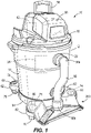
- FIG. 1 illustrates a vacuum cleaner 10 to be coupled to an accessory tool 200.
- the vacuum cleaner 10 includes a body 12 movable over a surface S.
- the body 12 includes a base 14 and a lid 18 selectively removable from the base 14.
- the vacuum cleaner 10 includes a vacuum cleaner inlet 22, a separator 26, and a clean air outlet.
- the vacuum cleaner inlet 22 is provided on the base 14.
- the separator 26 is in fluid communication with the vacuum cleaner inlet 22 and is configured to separate debris (e.g., solid debris and/or liquid working fluid) from clean air.
- the vacuum cleaner inlet 22 may act as a suction port for the vacuum cleaner 10.
- the clean air outlet is in fluid communication with the separator 26 opposite the vacuum cleaner inlet 22 such that the clean air that passes through the separator 26 is exhausted through the clean air outlet to the surroundings of the vacuum cleaner 10.
- the illustrated base 14 functions as a debris collector to receive solid debris and/or liquid working fluid that is separated by the separator 26.
- the illustrated vacuum cleaner 10 is a canister style wet/dry vacuum cleaner operable to vacuum solid debris and/or liquid working fluid.
- a seal is provided between the base 14 and the lid 18.
- Other arrangements of the vacuum cleaner 10 are possible, such as an upright extractor, a stick or pole vacuum, or a handheld vacuum.
- the vacuum cleaner 10 includes a motor 42 disposed in the body 12.
- the motor 42 is configured as a suction source to generate suction to draw fluid through the vacuum cleaner inlet 22.
- the motor 42 is powered by a power source 50.
- the power source 50 may be a battery pack which is selectively coupled to the lid 18 of the vacuum cleaner 10. Other arrangements or locations of the power source 50 are possible.
- some embodiments may include a power cord for connecting the vacuum cleaner 10 to a main power grid for receiving alternating current.
- the base 14 is supported on a chassis 54 including at least one wheel 70.
- a user operating the vacuum cleaner 10 may grasp a portion of the vacuum cleaner 10 to translate the vacuum cleaner 10 along a surface S towards a portion of the surface S that needs to be cleaned.
- the user may also lift the vacuum cleaner 10 from the surface S using a handle 58 coupled to the lid 18 to move the vacuum cleaner 10 to the portion of the surface S that needs to be cleaned.
- the illustrated embodiment includes a plurality of wheels 70.
- the wheels 70 include caster-type wheels, which allow the vacuum cleaner 10 to slide along the surface S in any direction.
- the chassis 54 includes a plurality of feet 62 extending radially outwardly from the base 14. Each of the plurality of feet 62 support one of the plurality of wheels 70 below the foot 62. Each of the plurality of feet 62 include an accessory connector 74 positioned above the foot 62.
- the accessory connector 74 is configured to mechanically secure an accessory of the vacuum cleaner 10 to the vacuum cleaner 10.
- the accessory may be a suction nozzle, an extension tube, a flexible hose 90, an accessory tool such as a dustpan attachment 200, or the like.
- the accessory connector 74 includes an annular recess 66.
- the accessory may include a cylindrical end that fits within the annular recess 66.
- the accessory connector 74 may secure the accessory to the vacuum cleaner 10 during use or for storage of the accessory on the vacuum cleaner 10 while the accessory is not in use.
- the illustrated embodiment includes a plurality of accessory connectors 74 on the chassis 54.
- the vacuum cleaner 10 may include additional accessory storage on the lid 18.
- the additional accessory storage may use accessory connectors similar to accessory connectors 74 or may use different mounting methods to retain accessories.
- the vacuum cleaner 10 may be used with an accessory such as the flexible hose 90 to extend the inlet of the vacuum cleaner 10.
- the flexible hose 90 includes a first hose end 90a, removably coupled to the vacuum cleaner inlet 22, and a second hose end 90b, opposite the first hose end 90a, which may act as a suction port for the vacuum cleaner 10.
- the second hose end 90b may be removably secured to one of the accessory tools.
- FIGS. 2-6 illustrate the accessory tool 200 formed as a dustpan attachment 200 in more detail.
- the accessory tool 200 may be used with other types of vacuum cleaners, such as upright cleaners, wet/dry vacuums, extractors, and more.
- the dustpan attachment 200 includes a housing 204.
- the housing 204 includes a top wall 208 and a plurality of walls 212 extending from the top wall 208 to a bottom edge 224.
- the plurality of walls 212 and the top wall 208 define a recess 228 in the housing 204, surrounded by the bottom edge 224.
- the bottom edge 224 may be positioned against the surface S.
- the bottom edge 224 includes a groove 232 to receive a sealing element 236 or sealing member 236.
- the sealing element 236 may include a resilient sealing material.
- the sealing element 236 may be formed as a rubber gasket. In some embodiments, other sealing materials may be used.
- the sealing element 236 cooperates with the surface S when the bottom edge 224 is placed against the surface S to prevent fluid flow under the bottom edge 224.
- the housing 204 includes one or more mounting surfaces 240 which may couple the accessory tool 200 to the vacuum cleaner 10.
- the mounting surfaces 240 include a pair of flanges 244 positioned on either side of the housing 204 and extending rearwardly and upwardly from the bottom edge 224.
- Each flange 244 includes an annular projection 246 extending from a lower surface of the flange 244.
- the annular projection 246 may have a diameter sized to correspond to the diameter of the annular recess 66 of the accessory connector 74.
- the accessory tool 200 may be mounted on the vacuum cleaner 10 by fitting each annular projection 246 into one of the annular recesses 66.
- the annular projections 246 function as a pair of attachment features on the dustpan attachment 200 and the annular recesses 66 function as a pair of mounting features on the vacuum cleaner 10.
- the bottom edge 224 may be supported in contact with the surface S to prevent air from flowing underneath the bottom edge 224. In other embodiments, the bottom edge 224 may be supported adjacent the surface S to minimize flow underneath the bottom edge 224.
- the housing 204 also includes a front opening 248.
- a front lip 252 extends from a front edge 256 of the top wall 208.
- the front opening 248 is positioned beneath the front lip 252 and forms a suction inlet 260 when the bottom edge 224 is positioned against the surface S.
- the front opening 248 opens forwardly and extends along almost the entire width of the housing 204.
- the front opening 248 has a width W of between 6 and 20 inches. More specifically, the width W may correspond to a width of a head of a standard sweeping implement such as a broom B ( FIG. 6 ).
- the suction inlet 260 extends between a first end 261 of the housing 204, adjacent one end of the suction inlet 260, and a second end 262 of the housing 204, adjacent the opposite end of the suction inlet 260.
- the bottom edge 224 also extends between the first end 261 and the second end 262 around the recess 228.
- the bottom edge 224 includes resilient sealing material continuously between the first end 261 of the housing 204 and the second end 262 of the housing 204.
- the suction inlet 260 extends into the housing 204 along a first axis A1 ( FIG. 5 ). When the bottom edge 224 is positioned against the surface S, the first axis A1 is generally horizontal.
- the suction inlet 260 has a cross sectional area C1 (or first area C1) measured perpendicular to the first axis A1.
- the suction inlet 260 is generally rectangular in shape.
- the dustpan attachment 200 further includes a vacuum port 264.
- the vacuum port 264 is coupled to the top wall 208 of the housing 204.
- the vacuum port 264 may extend from any of the plurality of walls 212, or may extend through or span multiple walls, including the top wall 208 or the plurality of walls 212.
- the vacuum port 264 includes a connector 268 extending from the top wall 208.
- the connector 268 includes an outer wall 272 defining a channel 276 which extends along a second axis A2 through the housing 204 and connects to the recess 228. When the bottom edge 224 is positioned against the surface S, the second axis A2 extends generally vertically.
- the vacuum port 264 has a generally circular shape and a cross sectional area C2 (or second area C2) measured perpendicular to the second axis A2.
- the cross sectional area C2 of the vacuum port 264 is generally equal in size to the cross sectional area C1 of the suction inlet 260.
- the recess 228 cooperates with the surface S to create a suction channel 280.
- the sealing element 236 helps to seal the suction channel 280 around the bottom edge 224.
- the suction channel 280 extends between the suction inlet 260 and the vacuum port 264.
- the suction channel 280 converges in the width direction, such that the air is funneled toward the vacuum port 264.
- the vacuum port 264 may be removably coupled to the flexible hose 90. This effectively moves the inlet of the vacuum cleaner 10 to the suction inlet 260 of the dustpan attachment 200. As such, the vacuum cleaner inlet 22 is in fluid communication with the suction inlet 260.
- the fluid flow path extends from the suction inlet 260 of the dustpan attachment 200, through the flexible hose 90, and into the vacuum cleaner inlet 22.
- the flanges 244 can be removed from the accessory connectors 74 and the accessory tool 200 may be movable along the surface S to a position spaced from the body 12 while connected to the vacuum cleaner inlet 22 via the flexible hose 90. This affords a range of motion for the accessory tool 200 to move relative to the base 14 and the lid 18.
- a suction zone 284 (also referred to as a suction area 284) may be created adjacent to the suction inlet 260.
- the vacuum cleaner 10 can be powered on, so that the motor 42 creates a suction flow through the vacuum cleaner 10 to the suction zone 284.
- An operator can use a sweeping implement such as a broom B to move debris across the surface S into the suction zone 284. Debris that enters the suction zone 284 is drawn into the dustpan attachment 200 through the suction inlet 260.
- Debris is then transmitted through the suction channel 280, the channel 276 of the vacuum port 264, the flexible hose 90, the vacuum cleaner inlet 22, and to the separator 26. Debris is then collected in the base 14 and clean air is exhausted through the clean air outlet. Once the surface S has been cleaned, the vacuum cleaner 10 can be powered off.
- the dustpan attachment 200 can be removed from the flexible hose 90.
- the flexible hose 90 can be removed from the vacuum cleaner inlet 22 or can be coupled to a different accessory tool.
- the dustpan attachment 200 can remain coupled to the accessory connectors 74 or be removed and stored elsewhere.
- the debris collected in the base 14 can be emptied.
- the vacuum cleaner 10 can be moved and stored as needed.
Landscapes
- Engineering & Computer Science (AREA)
- Mechanical Engineering (AREA)
- Nozzles For Electric Vacuum Cleaners (AREA)
- Electric Vacuum Cleaner (AREA)
Abstract
Description
- This application claims priority to
U.S. Provisional Patent Application No. 63/183,305, filed on May 3, 2021 - The present invention relates to accessory tools for vacuum cleaners, and more particularly to a dustpan vacuum cleaner accessory tool.
- Vacuums typically include impeller units which generate suction fluid flow into a separator which separates suction debris from an airflow. Vacuums include dirty fluid inlets in fluid communication with the impeller unit to direct dirty fluid from work surfaces and into the separator. Occasionally, dirty fluid inlets are provided by hoses coupled to the separator. Suction nozzle attachments or other accessory tools are removably attached to the separator via the hose to extend the reach of the suction.
- The disclosure provides, in one aspect, a vacuum cleaner including a body movable over a surface to be cleaner, a suction source positioned in the body, and a suction port in fluid communication with the suction source. The body includes a plurality of feet. A dustpan attachment is removably coupled to the body. The dustpan attachment includes a housing having a recess and a vacuum port fluidly coupled to the suction port, and a pair of flanges extending from the housing. Each flange is removably coupled to a respective one of the plurality of feet. When each of the pair of flanges is coupled to a respective one of the plurality of feet, the recess cooperates with the surface to form a suction channel having a suction inlet formed in a front of the housing and opening forwardly, wherein the suction inlet is in fluid communication with the suction port.
- The disclosure provides, in another independent aspect, a dustpan attachment for use with a vacuum cleaner configured to clean a surface. The vacuum cleaner includes a body, a suction port, and a suction source disposed in the body for generating airflow through the suction port. The dustpan attachment includes a housing, a vacuum port extending through the housing, and a recess defined within the housing. The vacuum port is configured to fluidly couple to the suction port. The housing includes a top wall and a plurality of walls extending from the top wall to a bottom edge. The bottom edge is configured to contact the surface. When the bottom edge contacts the surface, the recess is configured to cooperate with the surface to form a suction channel having a suction inlet in communication with the vacuum port and formed in a front of the housing and opening forwardly. A pair of flanges extends from the housing and is configured to removably couple to the body.
- The disclosure provides, in another independent aspect, a method of using a dustpan attachment with a vacuum cleaner to clean a surface. The vacuum cleaner includes a body, a suction source positioned within the body, and a suction port in fluid communication with the suction source. The method includes connecting a pair of attachment features on the dustpan attachment to a pair of mounting features of the vacuum cleaner, thereby positioning the dustpan attachment adjacent the surface and forming a suction inlet at a front thereof. Then, connecting the suction port with a vacuum port of the dustpan attachment. Then, operating the suction source to draw air through the suction inlet into the body.
- Other features and aspects of the invention will become apparent by consideration of the following detailed description and accompanying drawings.
-
-
FIG. 1 illustrates an accessory tool removably coupled to a vacuum cleaner. -
FIG. 2 illustrates a perspective view of the accessory tool ofFIG. 1 . -
FIG. 3 illustrates a bottom perspective view of the accessory tool ofFIG. 1 . -
FIG. 4 illustrates a front view of the accessory tool ofFIG. 1 . -
FIG. 5 illustrates a cross sectional view of the accessory tool ofFIG. 1 . -
FIG. 6 illustrates the accessory tool ofFIG. 1 in use with the vacuum cleaner and a sweeping implement. - Before any embodiments of the invention are explained in detail, it is to be understood that the invention is not limited in its application to the details of construction and the arrangement of components set forth in the following description or illustrated in the following drawings. The invention is capable of other embodiments and of being practiced or of being carried out in various ways.
-
FIG. 1 illustrates avacuum cleaner 10 to be coupled to anaccessory tool 200. Thevacuum cleaner 10 includes abody 12 movable over a surface S. Thebody 12 includes abase 14 and alid 18 selectively removable from thebase 14. Thevacuum cleaner 10 includes avacuum cleaner inlet 22, aseparator 26, and a clean air outlet. Thevacuum cleaner inlet 22 is provided on thebase 14. Theseparator 26 is in fluid communication with thevacuum cleaner inlet 22 and is configured to separate debris (e.g., solid debris and/or liquid working fluid) from clean air. Thevacuum cleaner inlet 22 may act as a suction port for thevacuum cleaner 10. The clean air outlet is in fluid communication with theseparator 26 opposite thevacuum cleaner inlet 22 such that the clean air that passes through theseparator 26 is exhausted through the clean air outlet to the surroundings of thevacuum cleaner 10. The illustratedbase 14 functions as a debris collector to receive solid debris and/or liquid working fluid that is separated by theseparator 26. In the illustrated embodiment, the illustratedvacuum cleaner 10 is a canister style wet/dry vacuum cleaner operable to vacuum solid debris and/or liquid working fluid. Optionally, a seal is provided between thebase 14 and thelid 18. Other arrangements of thevacuum cleaner 10 are possible, such as an upright extractor, a stick or pole vacuum, or a handheld vacuum. - The
vacuum cleaner 10 includes amotor 42 disposed in thebody 12. Themotor 42 is configured as a suction source to generate suction to draw fluid through thevacuum cleaner inlet 22. Themotor 42 is powered by apower source 50. Thepower source 50 may be a battery pack which is selectively coupled to thelid 18 of thevacuum cleaner 10. Other arrangements or locations of thepower source 50 are possible. For example, some embodiments may include a power cord for connecting thevacuum cleaner 10 to a main power grid for receiving alternating current. - The
base 14 is supported on achassis 54 including at least onewheel 70. A user operating thevacuum cleaner 10 may grasp a portion of thevacuum cleaner 10 to translate thevacuum cleaner 10 along a surface S towards a portion of the surface S that needs to be cleaned. The user may also lift thevacuum cleaner 10 from the surface S using ahandle 58 coupled to thelid 18 to move thevacuum cleaner 10 to the portion of the surface S that needs to be cleaned. - The illustrated embodiment includes a plurality of
wheels 70. Thewheels 70 include caster-type wheels, which allow thevacuum cleaner 10 to slide along the surface S in any direction. Thechassis 54 includes a plurality offeet 62 extending radially outwardly from thebase 14. Each of the plurality offeet 62 support one of the plurality ofwheels 70 below thefoot 62. Each of the plurality offeet 62 include anaccessory connector 74 positioned above thefoot 62. Theaccessory connector 74 is configured to mechanically secure an accessory of thevacuum cleaner 10 to thevacuum cleaner 10. The accessory may be a suction nozzle, an extension tube, aflexible hose 90, an accessory tool such as adustpan attachment 200, or the like. Theaccessory connector 74 includes anannular recess 66. The accessory may include a cylindrical end that fits within theannular recess 66. Theaccessory connector 74 may secure the accessory to thevacuum cleaner 10 during use or for storage of the accessory on thevacuum cleaner 10 while the accessory is not in use. The illustrated embodiment includes a plurality ofaccessory connectors 74 on thechassis 54. Thevacuum cleaner 10 may include additional accessory storage on thelid 18. The additional accessory storage may use accessory connectors similar toaccessory connectors 74 or may use different mounting methods to retain accessories. - With reference to
FIG. 1 , thevacuum cleaner 10 may be used with an accessory such as theflexible hose 90 to extend the inlet of thevacuum cleaner 10. Theflexible hose 90 includes afirst hose end 90a, removably coupled to the vacuumcleaner inlet 22, and asecond hose end 90b, opposite thefirst hose end 90a, which may act as a suction port for thevacuum cleaner 10. Thesecond hose end 90b may be removably secured to one of the accessory tools. -
FIGS. 2-6 illustrate theaccessory tool 200 formed as adustpan attachment 200 in more detail. Theaccessory tool 200 may be used with other types of vacuum cleaners, such as upright cleaners, wet/dry vacuums, extractors, and more. - As shown in
FIGS. 2 and3 , thedustpan attachment 200 includes ahousing 204. Thehousing 204 includes atop wall 208 and a plurality ofwalls 212 extending from thetop wall 208 to abottom edge 224. The plurality ofwalls 212 and thetop wall 208 define arecess 228 in thehousing 204, surrounded by thebottom edge 224. Thebottom edge 224 may be positioned against the surface S. Thebottom edge 224 includes agroove 232 to receive asealing element 236 or sealingmember 236. The sealingelement 236 may include a resilient sealing material. For example, the sealingelement 236 may be formed as a rubber gasket. In some embodiments, other sealing materials may be used. The sealingelement 236 cooperates with the surface S when thebottom edge 224 is placed against the surface S to prevent fluid flow under thebottom edge 224. - The
housing 204 includes one or more mountingsurfaces 240 which may couple theaccessory tool 200 to thevacuum cleaner 10. In the illustrated embodiment, the mountingsurfaces 240 include a pair offlanges 244 positioned on either side of thehousing 204 and extending rearwardly and upwardly from thebottom edge 224. Eachflange 244 includes anannular projection 246 extending from a lower surface of theflange 244. Theannular projection 246 may have a diameter sized to correspond to the diameter of theannular recess 66 of theaccessory connector 74. Theaccessory tool 200 may be mounted on thevacuum cleaner 10 by fitting eachannular projection 246 into one of theannular recesses 66. Therefore, theannular projections 246 function as a pair of attachment features on thedustpan attachment 200 and theannular recesses 66 function as a pair of mounting features on thevacuum cleaner 10. When theaccessory tool 200 is mounted to thevacuum cleaner 10, thebottom edge 224 may be supported in contact with the surface S to prevent air from flowing underneath thebottom edge 224. In other embodiments, thebottom edge 224 may be supported adjacent the surface S to minimize flow underneath thebottom edge 224. - With reference to
FIGS. 2 and4 , thehousing 204 also includes afront opening 248. In the illustrated embodiment, afront lip 252 extends from afront edge 256 of thetop wall 208. Thefront opening 248 is positioned beneath thefront lip 252 and forms asuction inlet 260 when thebottom edge 224 is positioned against the surface S. Thefront opening 248 opens forwardly and extends along almost the entire width of thehousing 204. In some embodiments, thefront opening 248 has a width W of between 6 and 20 inches. More specifically, the width W may correspond to a width of a head of a standard sweeping implement such as a broom B (FIG. 6 ). Thesuction inlet 260 extends between afirst end 261 of thehousing 204, adjacent one end of thesuction inlet 260, and asecond end 262 of thehousing 204, adjacent the opposite end of thesuction inlet 260. Thebottom edge 224 also extends between thefirst end 261 and thesecond end 262 around therecess 228. Thebottom edge 224 includes resilient sealing material continuously between thefirst end 261 of thehousing 204 and thesecond end 262 of thehousing 204. Thesuction inlet 260 extends into thehousing 204 along a first axis A1 (FIG. 5 ). When thebottom edge 224 is positioned against the surface S, the first axis A1 is generally horizontal. Thesuction inlet 260 has a cross sectional area C1 (or first area C1) measured perpendicular to the first axis A1. Thesuction inlet 260 is generally rectangular in shape. - As shown best in
FIG. 2 , thedustpan attachment 200 further includes avacuum port 264. In the illustrated embodiment, thevacuum port 264 is coupled to thetop wall 208 of thehousing 204. In other embodiments, thevacuum port 264 may extend from any of the plurality ofwalls 212, or may extend through or span multiple walls, including thetop wall 208 or the plurality ofwalls 212. In the illustrated embodiment, thevacuum port 264 includes aconnector 268 extending from thetop wall 208. Theconnector 268 includes anouter wall 272 defining achannel 276 which extends along a second axis A2 through thehousing 204 and connects to therecess 228. When thebottom edge 224 is positioned against the surface S, the second axis A2 extends generally vertically. Thevacuum port 264 has a generally circular shape and a cross sectional area C2 (or second area C2) measured perpendicular to the second axis A2. The cross sectional area C2 of thevacuum port 264 is generally equal in size to the cross sectional area C1 of thesuction inlet 260. - As shown in
FIGS. 4 and 5 , when thebottom edge 224 is positioned against the surface S, therecess 228 cooperates with the surface S to create asuction channel 280. The sealingelement 236 helps to seal thesuction channel 280 around thebottom edge 224. Thesuction channel 280 extends between thesuction inlet 260 and thevacuum port 264. Thesuction channel 280 converges in the width direction, such that the air is funneled toward thevacuum port 264. Thevacuum port 264 may be removably coupled to theflexible hose 90. This effectively moves the inlet of thevacuum cleaner 10 to thesuction inlet 260 of thedustpan attachment 200. As such, the vacuumcleaner inlet 22 is in fluid communication with thesuction inlet 260. When theflexible hose 90 is secured to the vacuumcleaner inlet 22 and thedustpan attachment 200, the fluid flow path extends from thesuction inlet 260 of thedustpan attachment 200, through theflexible hose 90, and into the vacuumcleaner inlet 22. In some embodiments, theflanges 244 can be removed from theaccessory connectors 74 and theaccessory tool 200 may be movable along the surface S to a position spaced from thebody 12 while connected to the vacuumcleaner inlet 22 via theflexible hose 90. This affords a range of motion for theaccessory tool 200 to move relative to thebase 14 and thelid 18. - As shown in
FIGS. 5 and6 , while connected to thevacuum cleaner 10 and positioned with thebottom edge 224 on the surface S, a suction zone 284 (also referred to as a suction area 284) may be created adjacent to thesuction inlet 260. In use, thevacuum cleaner 10 can be powered on, so that themotor 42 creates a suction flow through thevacuum cleaner 10 to thesuction zone 284. An operator can use a sweeping implement such as a broom B to move debris across the surface S into thesuction zone 284. Debris that enters thesuction zone 284 is drawn into thedustpan attachment 200 through thesuction inlet 260. Debris is then transmitted through thesuction channel 280, thechannel 276 of thevacuum port 264, theflexible hose 90, the vacuumcleaner inlet 22, and to theseparator 26. Debris is then collected in thebase 14 and clean air is exhausted through the clean air outlet. Once the surface S has been cleaned, thevacuum cleaner 10 can be powered off. Thedustpan attachment 200 can be removed from theflexible hose 90. Theflexible hose 90 can be removed from the vacuumcleaner inlet 22 or can be coupled to a different accessory tool. Thedustpan attachment 200 can remain coupled to theaccessory connectors 74 or be removed and stored elsewhere. The debris collected in the base 14 can be emptied. Thevacuum cleaner 10 can be moved and stored as needed. - Various features of the invention are set forth in the following claims.
Claims (20)
- A vacuum cleaner comprising:a body movable over a surface to be cleaned, the body including a plurality of feet;a suction source positioned in the body;a suction port in fluid communication with the suction source; anda dustpan attachment removably coupled to the body, the dustpan attachment including:a housing including a recess and a vacuum port fluidly coupled to the suction port; anda pair of flanges extending from the housing, wherein each flange is removably coupled to a respective one of the plurality of feet;wherein when each of the pair of flanges is coupled to a respective one of the plurality of feet, the recess cooperates with the surface to form a suction channel having a suction inlet formed in a front of the housing and opening forwardly, wherein the suction inlet is in fluid communication with the suction port.
- The vacuum cleaner of claim 1, further comprising a debris collector in fluid communication with the vacuum port and the suction source, wherein debris is drawn through the suction inlet and transmitted to the debris collector.
- The vacuum cleaner of claim 2, wherein the suction source creates a suction area adjacent the suction inlet, wherein when debris enters the suction area, it is drawn through the suction inlet to the debris collector.
- The vacuum cleaner of claim 3, wherein debris can be swept into the suction area.
- The vacuum cleaner of claim 1, wherein the housing includes a top wall and a plurality of walls extending from the top wall to a bottom edge, the bottom edge configured to contact the surface.
- The vacuum cleaner of claim 5, wherein the vacuum port extends through the top wall.
- The vacuum cleaner of claim 1, wherein a flexible hose is coupled between the suction port and the vacuum port.
- The vacuum cleaner of claim 1, wherein the pair of flanges of the dustpan attachment can be removed from the vacuum cleaner and the dustpan attachment can be positioned on the surface spaced from the body.
- The vacuum cleaner of claim 1, wherein each flange includes an annular projection, and each foot includes an annular recess, and wherein the dustpan attachment is coupled to the body by positioning the annular projections within the annular recesses.
- The vacuum cleaner of claim 9, wherein each of the annular projections extends from a lower surface of the respective flange.
- A dustpan attachment for use with a vacuum cleaner configured to clean a surface, the vacuum cleaner having a body, a suction port, and a suction source disposed in the body for generating airflow through the suction port, the dustpan attachment comprising:a housing including a top wall and a plurality of walls extending from the top wall to a bottom edge, the bottom edge configured to contact the surface;a vacuum port extending through the housing, the vacuum port configured to fluidly couple to the suction port;a recess defined within the housing, wherein when the bottom edge contacts the surface, the recess is configured to cooperate with the surface to form a suction channel having a suction inlet in communication with the vacuum port and formed in a front of the housing and opening forwardly; anda pair of flanges extending from the housing, the pair of flanges configured to removably couple to the body.
- The dustpan attachment of claim 11, wherein the housing defines a first end at one end of the suction inlet and second end at an opposite end of the suction inlet and wherein the bottom edge includes a resilient sealing material extending between the first end and second end.
- The dustpan attachment of claim 12, wherein when the pair of flanges are coupled to the body, the resilient sealing material contacts the surface continuously between the first end and second end.
- The dustpan attachment of claim 11, wherein the suction inlet defines a first area, and the vacuum port defines a second area, and wherein the first area and the second area are the equal in size.
- The dustpan attachment of claim 11, wherein the vacuum port extends through the top wall of the housing.
- The dustpan attachment of claim 15, wherein the suction channel converges in a width direction from the suction inlet to the vacuum port.
- The dustpan attachment of claim 11, wherein the dustpan attachment can be removed from the body and positioned on the surface to be cleaned spaced from the body.
- A method of using a dustpan attachment with a vacuum cleaner to clean a surface, the vacuum cleaner including a body, a suction source positioned within the body, and a suction port in fluid communication with the suction source, the method comprising:connecting a pair of attachment features on the dustpan attachment to a pair of mounting features of the vacuum cleaner, thereby positioning the dustpan attachment adjacent the surface and forming a suction inlet at a front thereof;connecting the suction port with a vacuum port of the dustpan attachment; andoperating the suction source to draw air through the suction inlet into the body.
- The method of claim 18, wherein each of the pair of mounting features is positioned on a respective foot of the vacuum cleaner, and wherein each of the pair of mounting features includes an annular recess.
- The method of claim 19, wherein each of the pair of attachment features includes an annular projection, and wherein connecting the pair of attachment features to the pair of mounting features includes positioning each annular projection in a corresponding annular recess.
Applications Claiming Priority (1)
| Application Number | Priority Date | Filing Date | Title |
|---|---|---|---|
| US202163183305P | 2021-05-03 | 2021-05-03 |
Publications (4)
| Publication Number | Publication Date |
|---|---|
| EP4094658A2 true EP4094658A2 (en) | 2022-11-30 |
| EP4094658A3 EP4094658A3 (en) | 2023-02-22 |
| EP4094658B1 EP4094658B1 (en) | 2025-07-30 |
| EP4094658C0 EP4094658C0 (en) | 2025-07-30 |
Family
ID=81579477
Family Applications (1)
| Application Number | Title | Priority Date | Filing Date |
|---|---|---|---|
| EP22171072.6A Active EP4094658B1 (en) | 2021-05-03 | 2022-05-02 | Dustpan accessory tool for vacuum cleaner |
Country Status (4)
| Country | Link |
|---|---|
| US (1) | US12245733B2 (en) |
| EP (1) | EP4094658B1 (en) |
| CN (1) | CN218515671U (en) |
| CA (1) | CA3157034A1 (en) |
Families Citing this family (1)
| Publication number | Priority date | Publication date | Assignee | Title |
|---|---|---|---|---|
| USD1015674S1 (en) * | 2022-02-11 | 2024-02-20 | Randall L. McPherson | Device for debris capture and retainment |
Family Cites Families (28)
| Publication number | Priority date | Publication date | Assignee | Title |
|---|---|---|---|---|
| US2242278A (en) | 1940-04-19 | 1941-05-20 | Jr Edward H Yonkers | Suction cleaner |
| US5839157A (en) * | 1996-05-06 | 1998-11-24 | Elgin Sweeper Company | Street sweeper pick-up head |
| CA2301424A1 (en) | 2000-03-16 | 2001-09-16 | Michael O'brien | Removable disaplaceable dustpan |
| US6584640B2 (en) | 2001-03-20 | 2003-07-01 | Roger P. Vanderlinden | Large area surface cleaning tool for suctioning both dust and debris |
| US6601266B1 (en) | 2001-08-06 | 2003-08-05 | Clifford C. Faraci | Ceiling scraper vacuum accessory |
| CN2726515Y (en) | 2004-04-29 | 2005-09-21 | 李潇 | Novel dustpan |
| US20060026790A1 (en) | 2004-08-04 | 2006-02-09 | Consilvio Alexander A | Dustpan with miniature on-board vacuum |
| US7412749B2 (en) | 2005-01-24 | 2008-08-19 | Euro-Pro Operating, Llc | Vacuum cleaner and floor dustpan system |
| US7877839B2 (en) * | 2006-11-20 | 2011-02-01 | Black & Decker Inc. | Wet and/or dry vacuum with floor collector |
| WO2009106612A1 (en) | 2008-02-27 | 2009-09-03 | Plastiflex Belgium | Mobile vacuum pan unit |
| CN101524256A (en) | 2008-03-05 | 2009-09-09 | 曾爱丽 | Environment-friendly ground cleaner |
| SE533279C2 (en) | 2008-12-22 | 2010-08-10 | Signe Grassman | Nozzle |
| US8556135B2 (en) | 2009-11-05 | 2013-10-15 | Dometic Corporation | 360° dip tube pick-up adapter |
| WO2012061884A1 (en) | 2010-11-10 | 2012-05-18 | Kitvac International Pty Ltd | Vacuum assembly |
| US9451854B2 (en) | 2011-02-17 | 2016-09-27 | Anthony Scott Diminick | Repositionable fluid suction devices |
| JP3178558U (en) | 2012-07-09 | 2012-09-20 | 健 藤江 | Dust collector connected to vacuum cleaner |
| GB2524324B (en) * | 2014-03-21 | 2016-07-13 | Dyson Technology Ltd | A surface treating head |
| CN204306782U (en) | 2014-11-03 | 2015-05-06 | 沈阳化工大学 | A kind of dustpan of dust-collecting type |
| CN204909336U (en) | 2015-07-22 | 2015-12-30 | 西安理工大学 | Dust absorption formula dustpan |
| CN204919454U (en) | 2015-09-23 | 2015-12-30 | 青岛宁夏路第二小学 | Collect dustpan for rubbish |
| CA2923194A1 (en) | 2016-03-08 | 2017-09-08 | Magdalene L. De Silva | Suction scraper device for pet hair remover |
| US10743739B2 (en) | 2016-05-09 | 2020-08-18 | Willy Kerntopf | Dry mop cleaner |
| CN206687671U (en) | 2016-11-10 | 2017-12-01 | 唐飞宇 | A kind of novel portable ground sewage cleaning device |
| US11071425B2 (en) * | 2017-08-29 | 2021-07-27 | Shop Vac Corporation | Wide-area vacuum nozzle |
| EP3632638A1 (en) | 2018-10-01 | 2020-04-08 | Hilti Aktiengesellschaft | Suction device for a core drilling device |
| CN215605351U (en) | 2018-12-18 | 2022-01-25 | 尚科宁家运营有限公司 | Cleaning device replacement head |
| ES1230529Y (en) | 2019-02-15 | 2019-08-23 | Romero David Manuel Usen | Pickup with suction function and non-return system |
| CN211484434U (en) | 2019-11-13 | 2020-09-15 | 永康市杰创工业产品设计有限公司 | Vertical dustpan not easy to fall |
-
2022
- 2022-04-29 CA CA3157034A patent/CA3157034A1/en active Pending
- 2022-04-29 US US17/732,812 patent/US12245733B2/en active Active
- 2022-05-02 EP EP22171072.6A patent/EP4094658B1/en active Active
- 2022-05-05 CN CN202221056475.9U patent/CN218515671U/en active Active
Also Published As
| Publication number | Publication date |
|---|---|
| CN218515671U (en) | 2023-02-24 |
| EP4094658B1 (en) | 2025-07-30 |
| CA3157034A1 (en) | 2022-11-03 |
| US12245733B2 (en) | 2025-03-11 |
| US20220346622A1 (en) | 2022-11-03 |
| EP4094658C0 (en) | 2025-07-30 |
| EP4094658A3 (en) | 2023-02-22 |
Similar Documents
| Publication | Publication Date | Title |
|---|---|---|
| US10993595B2 (en) | Cleaning device | |
| US8122562B2 (en) | Surface cleaning implement with independent suction nozzle and agitator | |
| US9907446B2 (en) | Floor tool for a vacuum cleaning appliance | |
| US9282864B2 (en) | Floor tool for a vacuum cleaning appliance | |
| US8220109B2 (en) | Handheld pet hair vacuum cleaner | |
| AU2013298315B2 (en) | A floor tool for a vacuum cleaning appliance | |
| EP2879558A1 (en) | A floor tool for a vacuum cleaning appliance | |
| US20180249871A1 (en) | Vacuum cleaner including a removable canister assembly | |
| US20140033469A1 (en) | Floor tool for a vacuum cleaning appliance | |
| EP3833233B1 (en) | Handheld vacuum cleaner | |
| EP4094658B1 (en) | Dustpan accessory tool for vacuum cleaner | |
| US20240415344A1 (en) | Surface cleaner | |
| EP4049572A2 (en) | Dustpan accessory tool for vacuum cleaner | |
| GB2468797A (en) | Handheld vacuum cleaner | |
| KR200364058Y1 (en) | A combination structure of switch for vacuum cleaner |
Legal Events
| Date | Code | Title | Description |
|---|---|---|---|
| PUAI | Public reference made under article 153(3) epc to a published international application that has entered the european phase |
Free format text: ORIGINAL CODE: 0009012 |
|
| STAA | Information on the status of an ep patent application or granted ep patent |
Free format text: STATUS: THE APPLICATION HAS BEEN PUBLISHED |
|
| AK | Designated contracting states |
Kind code of ref document: A2 Designated state(s): AL AT BE BG CH CY CZ DE DK EE ES FI FR GB GR HR HU IE IS IT LI LT LU LV MC MK MT NL NO PL PT RO RS SE SI SK SM TR |
|
| PUAL | Search report despatched |
Free format text: ORIGINAL CODE: 0009013 |
|
| AK | Designated contracting states |
Kind code of ref document: A3 Designated state(s): AL AT BE BG CH CY CZ DE DK EE ES FI FR GB GR HR HU IE IS IT LI LT LU LV MC MK MT NL NO PL PT RO RS SE SI SK SM TR |
|
| RIC1 | Information provided on ipc code assigned before grant |
Ipc: A47L 9/00 20060101ALI20230117BHEP Ipc: A47L 9/12 20060101ALI20230117BHEP Ipc: A47L 13/52 20060101ALI20230117BHEP Ipc: A47L 5/36 20060101ALI20230117BHEP Ipc: A47L 9/02 20060101AFI20230117BHEP |
|
| STAA | Information on the status of an ep patent application or granted ep patent |
Free format text: STATUS: REQUEST FOR EXAMINATION WAS MADE |
|
| 17P | Request for examination filed |
Effective date: 20230822 |
|
| RBV | Designated contracting states (corrected) |
Designated state(s): AL AT BE BG CH CY CZ DE DK EE ES FI FR GB GR HR HU IE IS IT LI LT LU LV MC MK MT NL NO PL PT RO RS SE SI SK SM TR |
|
| GRAP | Despatch of communication of intention to grant a patent |
Free format text: ORIGINAL CODE: EPIDOSNIGR1 |
|
| STAA | Information on the status of an ep patent application or granted ep patent |
Free format text: STATUS: GRANT OF PATENT IS INTENDED |
|
| INTG | Intention to grant announced |
Effective date: 20250304 |
|
| GRAS | Grant fee paid |
Free format text: ORIGINAL CODE: EPIDOSNIGR3 |
|
| GRAA | (expected) grant |
Free format text: ORIGINAL CODE: 0009210 |
|
| STAA | Information on the status of an ep patent application or granted ep patent |
Free format text: STATUS: THE PATENT HAS BEEN GRANTED |
|
| AK | Designated contracting states |
Kind code of ref document: B1 Designated state(s): AL AT BE BG CH CY CZ DE DK EE ES FI FR GB GR HR HU IE IS IT LI LT LU LV MC MK MT NL NO PL PT RO RS SE SI SK SM TR |
|
| REG | Reference to a national code |
Ref country code: GB Ref legal event code: FG4D |
|
| REG | Reference to a national code |
Ref country code: CH Ref legal event code: EP |
|
| REG | Reference to a national code |
Ref country code: DE Ref legal event code: R096 Ref document number: 602022018296 Country of ref document: DE |
|
| REG | Reference to a national code |
Ref country code: IE Ref legal event code: FG4D |
|
| U01 | Request for unitary effect filed |
Effective date: 20250828 |
|
| U07 | Unitary effect registered |
Designated state(s): AT BE BG DE DK EE FI FR IT LT LU LV MT NL PT RO SE SI Effective date: 20250903 |
|
| PG25 | Lapsed in a contracting state [announced via postgrant information from national office to epo] |
Ref country code: IS Free format text: LAPSE BECAUSE OF FAILURE TO SUBMIT A TRANSLATION OF THE DESCRIPTION OR TO PAY THE FEE WITHIN THE PRESCRIBED TIME-LIMIT Effective date: 20251130 |
|
| PG25 | Lapsed in a contracting state [announced via postgrant information from national office to epo] |
Ref country code: NO Free format text: LAPSE BECAUSE OF FAILURE TO SUBMIT A TRANSLATION OF THE DESCRIPTION OR TO PAY THE FEE WITHIN THE PRESCRIBED TIME-LIMIT Effective date: 20251030 |
|
| PG25 | Lapsed in a contracting state [announced via postgrant information from national office to epo] |
Ref country code: HR Free format text: LAPSE BECAUSE OF FAILURE TO SUBMIT A TRANSLATION OF THE DESCRIPTION OR TO PAY THE FEE WITHIN THE PRESCRIBED TIME-LIMIT Effective date: 20250730 |
|
| PG25 | Lapsed in a contracting state [announced via postgrant information from national office to epo] |
Ref country code: GR Free format text: LAPSE BECAUSE OF FAILURE TO SUBMIT A TRANSLATION OF THE DESCRIPTION OR TO PAY THE FEE WITHIN THE PRESCRIBED TIME-LIMIT Effective date: 20251031 |
|
| PG25 | Lapsed in a contracting state [announced via postgrant information from national office to epo] |
Ref country code: PL Free format text: LAPSE BECAUSE OF FAILURE TO SUBMIT A TRANSLATION OF THE DESCRIPTION OR TO PAY THE FEE WITHIN THE PRESCRIBED TIME-LIMIT Effective date: 20250730 |
|
| PG25 | Lapsed in a contracting state [announced via postgrant information from national office to epo] |
Ref country code: RS Free format text: LAPSE BECAUSE OF FAILURE TO SUBMIT A TRANSLATION OF THE DESCRIPTION OR TO PAY THE FEE WITHIN THE PRESCRIBED TIME-LIMIT Effective date: 20251030 |
|
| PG25 | Lapsed in a contracting state [announced via postgrant information from national office to epo] |
Ref country code: ES Free format text: LAPSE BECAUSE OF FAILURE TO SUBMIT A TRANSLATION OF THE DESCRIPTION OR TO PAY THE FEE WITHIN THE PRESCRIBED TIME-LIMIT Effective date: 20250730 |
|
| PG25 | Lapsed in a contracting state [announced via postgrant information from national office to epo] |
Ref country code: SM Free format text: LAPSE BECAUSE OF FAILURE TO SUBMIT A TRANSLATION OF THE DESCRIPTION OR TO PAY THE FEE WITHIN THE PRESCRIBED TIME-LIMIT Effective date: 20250730 |
|
| PG25 | Lapsed in a contracting state [announced via postgrant information from national office to epo] |
Ref country code: CZ Free format text: LAPSE BECAUSE OF FAILURE TO SUBMIT A TRANSLATION OF THE DESCRIPTION OR TO PAY THE FEE WITHIN THE PRESCRIBED TIME-LIMIT Effective date: 20250730 |
|
| PG25 | Lapsed in a contracting state [announced via postgrant information from national office to epo] |
Ref country code: SK Free format text: LAPSE BECAUSE OF FAILURE TO SUBMIT A TRANSLATION OF THE DESCRIPTION OR TO PAY THE FEE WITHIN THE PRESCRIBED TIME-LIMIT Effective date: 20250730 |
|
| PLBE | No opposition filed within time limit |
Free format text: ORIGINAL CODE: 0009261 |
|
| STAA | Information on the status of an ep patent application or granted ep patent |
Free format text: STATUS: NO OPPOSITION FILED WITHIN TIME LIMIT |
|
| REG | Reference to a national code |
Ref country code: CH Ref legal event code: L10 Free format text: ST27 STATUS EVENT CODE: U-0-0-L10-L00 (AS PROVIDED BY THE NATIONAL OFFICE) Effective date: 20260611 |
|
| U20 | Renewal fee for the european patent with unitary effect paid |
Year of fee payment: 5 Effective date: 20260527 |
|
| 26N | No opposition filed |
Effective date: 20260501 |
|
| PGFP | Annual fee paid to national office [announced via postgrant information from national office to epo] |
Ref country code: GB Payment date: 20260527 Year of fee payment: 5 |