EP4094555B1 - Bale retriever that generates driveable path for efficiency and to reduce compaction - Google Patents
Bale retriever that generates driveable path for efficiency and to reduce compaction Download PDFInfo
- Publication number
- EP4094555B1 EP4094555B1 EP22151756.8A EP22151756A EP4094555B1 EP 4094555 B1 EP4094555 B1 EP 4094555B1 EP 22151756 A EP22151756 A EP 22151756A EP 4094555 B1 EP4094555 B1 EP 4094555B1
- Authority
- EP
- European Patent Office
- Prior art keywords
- bale
- baler
- retriever
- path
- controller
- Prior art date
- Legal status (The legal status is an assumption and is not a legal conclusion. Google has not performed a legal analysis and makes no representation as to the accuracy of the status listed.)
- Active
Links
Images


Classifications
-
- G—PHYSICS
- G01—MEASURING; TESTING
- G01C—MEASURING DISTANCES, LEVELS OR BEARINGS; SURVEYING; NAVIGATION; GYROSCOPIC INSTRUMENTS; PHOTOGRAMMETRY OR VIDEOGRAMMETRY
- G01C21/00—Navigation; Navigational instruments not provided for in groups G01C1/00 - G01C19/00
- G01C21/005—Navigation; Navigational instruments not provided for in groups G01C1/00 - G01C19/00 with correlation of navigation data from several sources, e.g. map or contour matching
-
- A—HUMAN NECESSITIES
- A01—AGRICULTURE; FORESTRY; ANIMAL HUSBANDRY; HUNTING; TRAPPING; FISHING
- A01B—SOIL WORKING IN AGRICULTURE OR FORESTRY; PARTS, DETAILS, OR ACCESSORIES OF AGRICULTURAL MACHINES OR IMPLEMENTS, IN GENERAL
- A01B69/00—Steering of agricultural machines or implements; Guiding agricultural machines or implements on a desired track
- A01B69/007—Steering or guiding of agricultural vehicles, e.g. steering of the tractor to keep the plough in the furrow
- A01B69/008—Steering or guiding of agricultural vehicles, e.g. steering of the tractor to keep the plough in the furrow automatic
-
- A—HUMAN NECESSITIES
- A01—AGRICULTURE; FORESTRY; ANIMAL HUSBANDRY; HUNTING; TRAPPING; FISHING
- A01B—SOIL WORKING IN AGRICULTURE OR FORESTRY; PARTS, DETAILS, OR ACCESSORIES OF AGRICULTURAL MACHINES OR IMPLEMENTS, IN GENERAL
- A01B79/00—Methods for working soil
- A01B79/005—Precision agriculture
-
- G—PHYSICS
- G01—MEASURING; TESTING
- G01C—MEASURING DISTANCES, LEVELS OR BEARINGS; SURVEYING; NAVIGATION; GYROSCOPIC INSTRUMENTS; PHOTOGRAMMETRY OR VIDEOGRAMMETRY
- G01C21/00—Navigation; Navigational instruments not provided for in groups G01C1/00 - G01C19/00
- G01C21/26—Navigation; Navigational instruments not provided for in groups G01C1/00 - G01C19/00 specially adapted for navigation in a road network
- G01C21/28—Navigation; Navigational instruments not provided for in groups G01C1/00 - G01C19/00 specially adapted for navigation in a road network with correlation of data from several navigational instruments
- G01C21/30—Map- or contour-matching
-
- G—PHYSICS
- G05—CONTROLLING; REGULATING
- G05D—SYSTEMS FOR CONTROLLING OR REGULATING NON-ELECTRIC VARIABLES
- G05D1/00—Control of position, course, altitude or attitude of land, water, air or space vehicles, e.g. using automatic pilots
- G05D1/02—Control of position or course in two dimensions
- G05D1/021—Control of position or course in two dimensions specially adapted to land vehicles
- G05D1/0268—Control of position or course in two dimensions specially adapted to land vehicles using internal positioning means
- G05D1/0274—Control of position or course in two dimensions specially adapted to land vehicles using internal positioning means using mapping information stored in a memory device
-
- G—PHYSICS
- G05—CONTROLLING; REGULATING
- G05D—SYSTEMS FOR CONTROLLING OR REGULATING NON-ELECTRIC VARIABLES
- G05D1/00—Control of position, course, altitude or attitude of land, water, air or space vehicles, e.g. using automatic pilots
- G05D1/02—Control of position or course in two dimensions
- G05D1/021—Control of position or course in two dimensions specially adapted to land vehicles
- G05D1/0276—Control of position or course in two dimensions specially adapted to land vehicles using signals provided by a source external to the vehicle
- G05D1/0278—Control of position or course in two dimensions specially adapted to land vehicles using signals provided by a source external to the vehicle using satellite positioning signals, e.g. GPS
-
- G—PHYSICS
- G05—CONTROLLING; REGULATING
- G05D—SYSTEMS FOR CONTROLLING OR REGULATING NON-ELECTRIC VARIABLES
- G05D1/00—Control of position, course, altitude or attitude of land, water, air or space vehicles, e.g. using automatic pilots
- G05D1/20—Control system inputs
- G05D1/24—Arrangements for determining position or orientation
- G05D1/246—Arrangements for determining position or orientation using environment maps, e.g. simultaneous localisation and mapping [SLAM]
-
- G—PHYSICS
- G05—CONTROLLING; REGULATING
- G05D—SYSTEMS FOR CONTROLLING OR REGULATING NON-ELECTRIC VARIABLES
- G05D1/00—Control of position, course, altitude or attitude of land, water, air or space vehicles, e.g. using automatic pilots
- G05D1/20—Control system inputs
- G05D1/24—Arrangements for determining position or orientation
- G05D1/247—Arrangements for determining position or orientation using signals provided by artificial sources external to the vehicle, e.g. navigation beacons
- G05D1/248—Arrangements for determining position or orientation using signals provided by artificial sources external to the vehicle, e.g. navigation beacons generated by satellites, e.g. GPS
-
- G—PHYSICS
- G01—MEASURING; TESTING
- G01C—MEASURING DISTANCES, LEVELS OR BEARINGS; SURVEYING; NAVIGATION; GYROSCOPIC INSTRUMENTS; PHOTOGRAMMETRY OR VIDEOGRAMMETRY
- G01C21/00—Navigation; Navigational instruments not provided for in groups G01C1/00 - G01C19/00
- G01C21/20—Instruments for performing navigational calculations
Definitions
- the present invention pertains to agricultural vehicles and, more specifically, to bale retrievers and systems for producing and transporting crop material bales.
- balers such as balers
- a typical baler has a crop collector, which also may be referred to as a "pickup", that utilizes tines or other elements to direct the cut crop material to a bale chamber that packs the crop material into a bale. After the crop material is packed into a bale with the desired size, the bale is ejected out the back of the baler.
- US 2019/289769 describes an agricultural baling system comprising a bale forming component configured to form a bale of agricultural material and a control system configured to determine that the bale is to be released from the baling system onto the terrain.
- the system is able to determine that the current location of the baling system has a slope above a threshold such that a different location needs to be determined which is spaced apart from the current location to release the bale onto the surface.
- US 2017/118918 discloses a method for performing a bale collection operation of bales which have been dropped to the surface of a field during a previous baling operation. Therefore, a plurality of baling paths associated with at least one bale which needs to be collected within the field are stored and are accessible. Further, a location of a staging area relative to the field for aggregating the bales is determined and a plurality of guidance lines to be traversed are generated to collect and deliver the bales to the staging area. The method further foresees in guiding the work vehicle along the guidance lines to collect the bales and deliver them to the staging area.
- bale retriever that can address some of the previously described issues of known bale retrievers.
- Exemplary embodiments disclosed herein provide a bale retriever with a controller that defines an expected location of a bale based on a baler travel path and/or a baler planned path to generate a steering control signal for controlling a steering assembly of the bale retriever.
- Exemplary embodiments disclosed herein also provide a bale retriever with a controller that generates a steering control signal that differs based on whether the controller is in an efficiency mode or a compaction mode and outputs the steering control signal to a steering assembly.
- a bale retriever is provided as set forth in claim 1.
- the controller may be further configured to receive a previous bale drop location signal corresponding to a location of a previously dropped bale and define the expected location of the at least one bale based at least partially on the received previous bale drop location signal.
- the at least one operating parameter may comprise at least one of a defined bale size or a travel speed of the at least one baler.
- the bale retriever may further comprise a communication interface configured to communicate with at least one of the at least one baler or a communication network.
- the controller may be configured to receive real-time signals corresponding to at least one of the baler planned path or the baler travel path via the communication interface.
- the controller may be further configured to predict an imminent travel path of the at least one baler and generate the steering control signal so the bale retriever does not cross the imminent travel path.
- controller can define the expected location of a bale based on a prediction of where a baler will drop the bale, so the bale retriever can operate simultaneously with the baler in a field.
- bale retrievers and balers can operate simultaneously in a field to expedite production and transportation of bales.
- controller generating two possibly different control signals allows a user to control whether the bale retriever operates to maximize fuel efficiency and/or minimize ground compaction.
- controller (212) may also be configured to define the expected location of the bale based simply on the baler travel signal by predicting at what locations the baler (112) is expected to drop bales and/or based on the previous bale drop location signal that corresponds to one or more locations in the field map (300) where the baler (112) has dropped a bale.
- the controller (212) may, for example, define the expected location of a bale (302) by calculating a volume of crop material collected (or expected to be collected) by the baler (112) as the baler (112) travels along the baler travel path (or is expected to travel along the baler planned path), collects crop material, and packs the crop material into forming bales; based on this calculation, the controller (212) may define the expected location of a bale (302) to be a location where the baler (112) is expected to have collected a defined volume of crop material to form the bale (302) and ejected the bale (302) onto the field.
- Additional other parameters that the controller (212) may take into account to define the expected location of a bale (302) include, but are not limited to: a defined (or target) bale diameter; a defined (target) bale mass; a current diameter of a forming bale; a current weight of a forming bale; a swath volume from a previous raking and/or mowing operation; a historical distance traveled by the baler (112) to make bales in neighboring windrows; a slope of areas in the field map (300); and/or a planned driving path of the baler (112), which can take into account, e.g., headlands and/or the next swath taken.
- the controller (212) can be configured to define the expected location of a bale (302) based on a variety of parameters.
- the controller (212) is configured to define at least one windrow, illustrated as a plurality of windrows (301) in FIG. 3 , on the field map (300) that correspond to windrows in the field.
- the windrow(s) (301) can be defined in a variety of ways.
- the windrow(s) (301) are defined based on swath lines that the baler (112) follows to travel through the field, with the swath lines being generally aligned with the windrows (301) so the baler (112) follows the windrows 301 to collect and pack crop material into bales (302), as illustrated.
- the swath lines define the baler planned path of the baler (112).
- the controller (212) is configured to define collected windrows (303), illustrated in dashed lines, on the field map (300). By defining the collected windrows (303) on the field map (300), the controller (212) can keep track of space on the field that is free of crop material, the significance of which will be defined further herein.
- the controller (212) may define a baler traveled path (304) on the field map (300) from the received baler travel signal and switch between an efficiency mode and a compaction mode to generate a steering control signal that is a shortest distance control signal and/or a compaction avoidance control signal.
- the generated steering control signal is output to the steering assembly (208) to steer the bale retriever (202) toward the expected location of the bale to collect the bale.
- the controller (212) may be configured to switch between the efficiency mode and the compaction mode based on, for example, operator input to directly make the switch.
- the controller (212) may be configured to automatically switch between the efficiency mode and the compaction mode based on a location within a field, e.g., switch to the efficiency mode in a portion of a field that is already heavily compacted and/or has a soil type that is less prone to compaction, and/or when the bale retriever (202) reaches certain fuel levels, e.g., switch to the compaction mode when the bale retriever (202) has a high level of fuel and/or the bale to be retrieved is in a portion of the field with soil that is prone to compaction.
- the foregoing ways of switching between the efficiency mode and the compaction mode are exemplary only, and other ways and/or rationales for the controller (212) switching between the modes are contemplated according to the present disclosure.
- the controller (212) is configured to generate the shortest distance control signal when in the efficiency mode and to generate the compaction avoidance control signal when in the compaction mode.
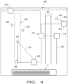
- the shortest distance control signal corresponds to a straight-line path (401), illustrated in dashed-line in FIG. 4 , from the bale retriever (202) to the expected location of the bale (302) that does not cross a windrow (301).
- the compaction avoidance control signal corresponds to a path (402), illustrated in solid-lines in FIG. 4 , from the bale retriever (202) to the expected location of the bale (302) that overlaps the bale traveled path. As illustrated in FIG.
- the straight-line path (401) represents a minimal distance that the bale retriever (202) must travel to get to the expected location of the bale (302), which minimizes the fuel consumption of the bale retriever (202) while also avoiding the bale retriever (202) driving over any windrows (301) and potentially damaging or dispersing crop material.
- the path (402) that overlaps the baler traveled path has the bale retriever (202) go over ground where the baler (112) has already traveled to reduce the risk of the bale retriever (202) compacting additional parts of the field, which can reduce yield. It should be appreciated that while the straight-line path (401) and the path (402) are illustrated as being different paths in FIG.
- the straight-line path (401) and the path (402) will overlap.
- the straight-line path (401) and the path (402) may overlap due to the bale retriever (202) following the swath line to the expected location of both bales (301).
- the generated steering control signal may be generated to avoid the bale retriever (202) driving into a bale drop zone Z until the bale retriever (202) is ready to drop its collected bale(s) at the bale drop zone Z.
- the controller (212) may be configured to determine a current location of the bale retriever (202), such as a GPS-based location, and define the expected location of the bale (302) as a GPS-based location.
- the controller (212) may define the straight-line path (401) using trigonometric functions and/or the Pythagorean theorem and the GPS-based current location of the bale retriever (202) and the expected location of the bale (302) to define a hypotenuse, which represents the straight-line path (401) from the current location of the bale retriever (202) to the expected location of the bale (302). It should be appreciated that the controller (212) may be configured to generate the shortest distance control signal in a variety of other ways, and the previously described way is just one exemplary way.
- the controller (212) After defining the straight-line path (401), the controller (212) also determines if the straight-line path (401) crosses a windrow (301) on the field map (300). For example, as illustrated in FIG. 4 , the bale retriever (202) could not travel to a bale (403) with a straight-line path and not cross one of the windrows (301). In such a case, the controller (212) may be configured to determine when the traveled path of the baler (112) has gone over the windrows (301), indicating that the windrows (301) have been collected, before generating the shortest distance control signal corresponding to the straight-line path toward the bale (403).
- the controller (212) is also configured to define one or more obstacle zones in the field map (300) and determine if the straight-line path (401) crosses an obstacle zone.
- the windrows (301) may be considered obstacle zones.
- Other possible obstacle zones may include, but are not limited to, an area where there is a tree or significant mud.
- the obstacle zones may be defined by an operator manually; alternatively, or in addition, the obstacle zones may be defined based on a path traveled by another vehicle, such as a mower-conditioner, which presumably avoids obstacles in the field.
- the controller (212) may be configured to compare the expected location of the bale (302) with the baler traveled path, which may both represent areas, and determine a shortest path between the location of the bale retriever (202) and the expected location of the bale (302) that is bound within the baler traveled path and the expected location of the bale (302). Generating the compaction avoidance control signal may also take other parameters into account, such as a location of headlands (406) in the field map (300), to determine the shortest path bound within the baler traveled path. As illustrated in FIG. 4 , the shortest path (402) corresponds to the bale retriever (202) traveling perpendicular and parallel to the windrows (301), similarly to the movement pattern utilized by the baler (112) as it collects and packs crop material into the bales (302).
- baler (112) and one bale retriever (202) of the system (200) can include multiple balers and bale retrievers.
- a second baler (412) which may be similar to the baler (112), may be simultaneously collecting and packing crop material into bales (302) on the field.
- a second bale retriever (404) which may be similar to the bale retriever (202), may be simultaneously collecting and transporting the formed bales (302).
- the second baler (412) and the second bale retriever (404) may both be communicating with the communication network (310) using respective interfaces and functioning similarly to the baler (112) and bale retriever (202).
- the controller (212) of the bale retriever (202) and the controller of the second bale retriever (404) may both be configured to receive a second baler travel signal corresponding to a travel path of the second baler (412) and define a second baler traveled path on the field map (300) from the received second baler travel signal from the second baler (412).
- the bale retrievers (202), (404) are configured to communicate with one another so their respective controllers may determine which of the bale retrievers (202), (404) is in a better position to collect a certain bale.
- the second bale retriever (404) may be more suited to collect the bale (403) because its straight-line path (405) to the bale (403) both is shorter than the corresponding straight-line path of the bale retriever (202) to the bale (403) and also does not cross any windrows (301) in the field.
- the controller of the second bale retriever (404) may determine that it has an acceptable straight-line path to the bale 403, whereas the bale retriever (202) does not, and generate a shortest distance control signal corresponding to the straight-line path (405) from the second bale retriever (404) to the expected location of the bale (403).
- the controller of the second bale retriever (404) may also be configured to output a bale retrieval signal to the controller (212) of the bale retriever (202) that causes the controller (212) of the bale retriever (202) to remove the expected location of the bale (403) from the field map (300), so the controller (212) does not output a steering control signal to the steering assembly (208) to steer the bale retriever (202) toward the bale (403).
- the controller (212) of the bale retriever (202) may output a bale retrieval signal to the controller of the second bale retriever (404) for bales (302), which are further from the second bale retriever (404) and cannot be reached by a straight-line path without crossing windrows (301), so the second bale retriever (404) does not steer toward the bales (302).
- the system (200) can be adapted to include a plurality of balers (112), (412) and/or bale retrievers (202), (404) to expedite production and transportation of crop material bales in a field.
- the controller (212) may be further configured to compare a first time interval that it will take for the baler (112) to clear the area of the imminent travel path (501) and collect the windrow (301), allowing the bale retriever (202) to follow the straight-line path (502) without crossing the imminent travel path (501) or the windrow 301, to a second time interval that it will take for the bale retriever (202) to follow a different path.
- the controller (212) may decide to wait for the baler (112) to collect the windrow (301) and then signal for the bale retriever (202) to follow the straight-line path (502) and collect the bale (503).
- the controller (212) decide to wait for the baler (112) to collect the windrow (301)
- a significant amount of fuel, and possibly time may be saved compared to the bale retriever (202) driving around the windrow 301 to collect the bale (503).
Landscapes
- Engineering & Computer Science (AREA)
- Radar, Positioning & Navigation (AREA)
- Remote Sensing (AREA)
- Physics & Mathematics (AREA)
- General Physics & Mathematics (AREA)
- Automation & Control Theory (AREA)
- Life Sciences & Earth Sciences (AREA)
- Aviation & Aerospace Engineering (AREA)
- Mechanical Engineering (AREA)
- Soil Sciences (AREA)
- Environmental Sciences (AREA)
- Harvester Elements (AREA)
Description
- The present invention pertains to agricultural vehicles and, more specifically, to bale retrievers and systems for producing and transporting crop material bales.
- Agricultural machines, such as balers, are well-known for collecting cut crop material and packing the cut crop material into bales for easier transport. A typical baler has a crop collector, which also may be referred to as a "pickup", that utilizes tines or other elements to direct the cut crop material to a bale chamber that packs the crop material into a bale. After the crop material is packed into a bale with the desired size, the bale is ejected out the back of the baler.
- Once the bale is formed, it needs to be transported from the field to a different location, such as a staging area, where the bale is stored. A bale retriever that includes a bale fork or similar pick up mechanism may be used to pick up multiple bales and move the bales to the staging area. While known bale retrievers are effective to pick up and transport bales, fuel use by the bale retriever remains an area where improvements can realize large economic gains. Further, known bale retrievers are not well-suited for use in picking up and transporting bales while one or more balers are actively producing bales in a field.
-
US 2019/289769 describes an agricultural baling system comprising a bale forming component configured to form a bale of agricultural material and a control system configured to determine that the bale is to be released from the baling system onto the terrain. The system is able to determine that the current location of the baling system has a slope above a threshold such that a different location needs to be determined which is spaced apart from the current location to release the bale onto the surface. -
US 2017/118918 discloses a method for performing a bale collection operation of bales which have been dropped to the surface of a field during a previous baling operation. Therefore, a plurality of baling paths associated with at least one bale which needs to be collected within the field are stored and are accessible. Further, a location of a staging area relative to the field for aggregating the bales is determined and a plurality of guidance lines to be traversed are generated to collect and deliver the bales to the staging area. The method further foresees in guiding the work vehicle along the guidance lines to collect the bales and deliver them to the staging area. - What is needed in the art is a bale retriever that can address some of the previously described issues of known bale retrievers.
- Exemplary embodiments disclosed herein provide a bale retriever with a controller that defines an expected location of a bale based on a baler travel path and/or a baler planned path to generate a steering control signal for controlling a steering assembly of the bale retriever.
- Exemplary embodiments disclosed herein also provide a bale retriever with a controller that generates a steering control signal that differs based on whether the controller is in an efficiency mode or a compaction mode and outputs the steering control signal to a steering assembly.
- In one aspect of the present invention, a bale retriever is provided as set forth in claim 1.
- The controller may be further configured to receive a previous bale drop location signal corresponding to a location of a previously dropped bale and define the expected location of the at least one bale based at least partially on the received previous bale drop location signal.
- The controller may be configured to define the expected bale location based at least partially on the baler planned path and at least one operating parameter of the at least one baler.
- The at least one operating parameter may comprise at least one of a defined bale size or a travel speed of the at least one baler.
- The bale retriever may further comprise a communication interface configured to communicate with at least one of the at least one baler or a communication network.
- The controller may be configured to receive real-time signals corresponding to at least one of the baler planned path or the baler travel path via the communication interface.
- The controller may be further configured to predict an imminent travel path of the at least one baler and generate the steering control signal so the bale retriever does not cross the imminent travel path.
- One possible advantage that may be realized by exemplary embodiments disclosed herein is that the controller can define the expected location of a bale based on a prediction of where a baler will drop the bale, so the bale retriever can operate simultaneously with the baler in a field.
- Another possible advantage that may be realized by exemplary embodiments disclosed herein is that multiple bale retrievers and balers can operate simultaneously in a field to expedite production and transportation of bales.
- Another possible advantage that may be realized by exemplary embodiments disclosed herein is that the controller generating two possibly different control signals allows a user to control whether the bale retriever operates to maximize fuel efficiency and/or minimize ground compaction.
- Another possible advantage that may be realized by exemplary embodiments disclosed herein is that real-time communication between the bale retriever and the baler can reduce the amount of time that a bale stays in the field outside the staging area with a low risk of the bale retriever driving into the baler, or vice versa.
- Yet another possible advantage that may be realized by exemplary embodiments disclosed herein is that the controller of the bale retriever can be configured to define the expected bale location based on the baler travel path and one or more operating parameters of the baler, allowing the bale retriever to move toward the expected location before the baler has finished forming the bale.
- For the purpose of illustration, there are shown in the drawings certain embodiments of the present invention. It should be understood, however, that the invention is not limited to the precise arrangements, dimensions, and instruments shown. Like numerals indicate like elements throughout the drawings. In the drawings:
-
FIG. 1 illustrates a side view of an exemplary embodiment of a tractor and a baler that may be part of a system for producing and transporting crop material bales, provided in accordance with the present disclosure; -
FIG. 2 illustrates a schematic diagram of an exemplary embodiment of a bale retriever that may be used as part of the system for producing and transporting crop material bales, provided in accordance with the present disclosure; -
FIG. 3 illustrates a schematic view of an exemplary embodiment of a field map that may be defined by a controller of the bale retriever ofFIG. 2 , in accordance with the present disclosure; -
FIG. 4 illustrates the field map ofFIG. 3 with both a straight-line path and a path from the bale retriever ofFIG. 2 to an expected location of a bale, in accordance with the present disclosure; -
FIG. 5 illustrates the field map ofFIG. 3 when the bale retriever defines an imminent travel path of the baler, in accordance with the present disclosure; -
FIG. 6 illustrates the field map ofFIG. 3 when the bale retriever defines the expected location of a bale based on a baler travel path and at least one operating parameter of the baler; -
FIG. 7 illustrates a flow chart of an exemplary embodiment of a method for controlling a bale retriever, provided in accordance with the present disclosure; and -
FIG. 8 illustrates a flow chart of another exemplary embodiment of a method for controlling a bale retriever, provided in accordance with the present disclosure. - Referring now to the drawings,
FIG. 1 illustrates a side view of an exemplary embodiment of a work vehicle (110) towing a baler (112) in accordance with the present disclosure to perform a baling operation within a field. As will be described further herein, the baler (112) may be part of a system (200) for producing and transporting crop material bales that includes the baler (112) and a bale retriever (202) (illustrated inFIG. 2 ). As shown, the work vehicle (110) is configured as an agricultural tractor, such as an operator-driven tractor or an autonomous tractor. However, in some embodiments, the work vehicle (110) may correspond to any other suitable vehicle configured to tow a baler across a field or that is otherwise configured to facilitate the performance of a baling operation, including an autonomous baling vehicle. Additionally, as shown, the baler (112) is configured as a round baler configured to generate round bales. However, in some embodiments, the baler (112) may have any other suitable configuration, including being configured to generate square or rectangular bales. It should be further appreciated that the baler (112), while shown as being towed by a tractor (110), may also be a self-propelled baler that does not rely on a separate vehicle for propulsion and/or power to function. - As shown in
FIG. 1 , the work vehicle (110) includes a pair of front wheels (114), a pair of rear wheels (116), and a chassis (118) coupled to and supported by the wheels (114), (116). An operator's cab (120) may be supported by a portion of the chassis (118) and may house various input devices for permitting an operator to control the operation of the work vehicle (110) and/or the baler (112). Additionally, the work vehicle (110) may include an engine and a transmission mounted on the chassis (118). The transmission may be operably coupled to the engine and may provide variably adjusted gear ratios for transferring engine power to the wheels (116) via a drive axle assembly. - As shown in
FIG. 1 , the work vehicle (110) may be coupled to the baler (112) via a tongue (122) mounted on a hitch (124) of the work vehicle (110) to allow the vehicle (110) to tow the baler (112) across the field. As such, the work vehicle (110) may, for example, guide the baler (112) toward crop material deposited in windrows on the field. As is generally understood, to collect the crop material, the baler (112) includes a crop collector (126) (shown schematically inFIG. 1 ) mounted on the front end of the baler (112). The crop collector (126) may, for example, have a rotating wheel with tines that collects crop material from the ground and directs the crop material toward a bale chamber (128) of the baler (112). Inside the bale chamber (128), rollers, belts, and/or other devices compact the crop material to form a generally cylindrically shaped bale (130). The bale (130) is contained within the baler (112) until ejection of the bale (130) is instructed (e.g., by the operator and/or a baler controller (131)). In some embodiments, the bale (130) may be automatically ejected from the baler (112) once the bale (130) is formed by the baler controller (131) detecting that the bale (130) is fully formed and outputting an appropriate ejection signal. - As shown in
FIG. 1 , the baler (112) may also include a tailgate (132) movable between a closed position (as shown in the illustrated embodiment) and an opened position via a suitable actuator assembly. The tailgate (132) and/or actuator assembly may be controlled to open and close by the baler controller (131). In the closed position, the tailgate (132) may confine or retain the bale (130) within the baler (112). In the open position, the tailgate (132) may rotate out of the way to allow the bale 130 to be ejected from the bale chamber (128). Additionally, as shown inFIG. 1 , the baler (112) may include a ramp (134) extending from its aft end that is configured to receive and direct the bale (130) away from the baler (112) as it is being ejected from the bale chamber (128). In some embodiments, the ramp (134) may be spring loaded, such that the ramp (134) is urged into a raised position, as illustrated. In such embodiments, the weight of the bale (130) on the ramp (134) may drive the ramp (134) to a lowered position in which the ramp (134) directs the bale (130) to the soil surface. Once the bale (130) is ejected, the bale (130) may roll down the ramp (134) and be deposited onto the field. As such, the ramp (134) may enable the bale (130) to maintain its shape and desired density by gently guiding the bale (130) onto the field. - It should be appreciated that the configuration of the work vehicle (110) described above and shown in
FIG. 1 is provided only as one example. Thus, it should be appreciated that the present disclosure may be readily adaptable to any manner of work vehicle configuration. For example, in an alternative embodiment, a separate frame or chassis may be provided to which the engine, transmission, and drive axle assembly are coupled, a configuration common in smaller tractors. Still other configurations may use an articulated chassis to steer the work vehicle (110), or rely on tracks in lieu of the wheels (114), (116). Additionally, as indicated previously, the work vehicle (110) may, in some embodiments, be configured as an autonomous vehicle. In such embodiments, the work vehicle (110) may include suitable components for providing autonomous vehicle operation and, depending on the vehicle configuration, need not include the operator's cab (120). - Additionally, it should be appreciated that the configuration of the baler (112) described above and shown in
FIG. 1 is provided only as one example. Thus, it should be appreciated that the present disclosure may be readily adaptable to any manner of baler configuration. For example, as indicated previously, the baler (112) may, in some embodiments, correspond to a square baler configured to generate square or rectangular bales. - Referring now to
FIG. 2 , a schematic view of an exemplary embodiment of a system (200) for producing and collecting crop material bales is illustrated in accordance with the present disclosure. In general, the system (200) will be described herein with reference to the work vehicle (110) and the baler (112) described previously with reference toFIG. 1 . However, it should be appreciated that the system (200) may generally be utilized with work vehicles having any suitable vehicle configuration and/or balers having any suitable baler configuration. Additionally, for purposes of providing an example of a bale production and collection operation, the system (200) will generally be described herein with reference to performance of the bale production and collection operation following the example baling operation described herein. However, it should be appreciated that the system (200) may generally be utilized to perform a bale collection and transportation operation following the performance of any suitable baling operation within any suitable field. - The
system 200 includes at least one baler (112) and at least one bale retriever (202) configured to collect bales previously deposited within a field. In some embodiments, the bale retriever (202) may be towed by the tractor (110) described previously with reference toFIG. 1 . For example, upon completion of the baling operation, the baler (112) may be unhitched from the tractor (110) and a suitable bale pick up or other implement (e.g., a bale spear) may be installed on the tractor (110) to allow for the collection of bales from the field. In some embodiments, the bale retriever (202) may correspond to another suitable vehicle that can be used to collect bales standing within the field, including any suitable autonomous vehicle and/or any suitable operator-driven vehicle (e.g., a skid-steer loader). It should be appreciated that, in some embodiments, the baler(s) (112) and the bale retriever(s) (202) are separate vehicles in the system (200) that can operate simultaneously within a field to produce and collect crop material bales. - As shown in
FIG. 2 , the bale retriever (202) may include various components for allowing the bale retriever (202) to be moved across the field during the bale collection operation. For example, the bale retriever (202) may include an engine (204) and a transmission (206) coupled to the engine (204) for propelling the vehicle (202) through the field. In addition, the bale retriever (202) may include a steering assembly (208) for steering the bale retriever (202). In some embodiments, the steering assembly (208) may be configured to be manually operated via the operator to steer the vehicle (202). The steering assembly (208) may also be configured to be automatically and/or autonomously controlled to allow the bale retriever (202) to be directed along a predetermined path(s) across the field, either additionally or alternatively to manual control of the steering assembly (208). For example, in some embodiments, the steering assembly (208) may include or form part of an auto-guidance system for automatically steering the bale retriever (202). In such an embodiment, the bale retriever (202) may correspond to a fully autonomous vehicle, a semi-autonomous vehicle, or an otherwise manually operated vehicle having one or more autonomous functions (e.g., automated steering or auto-guidance functions). The bale retriever (202) also includes a bale pick up (209), which may be a fork or other component that is configured to pick up crop material bales from a field and, for example, place the picked up bale on a holding platform (which may include a conveyor) of the bale retriever (202). - Additionally, the bale retriever (202) may also include a positioning device (210) configured to monitor or track the position of the vehicle (202) as it is traversed across a field. For example, in some embodiments, the positioning device (210) may be configured to determine the exact location of the bale retriever (202) using a satellite navigation position system (e.g. a GPS system, a Galileo positioning system, the Global Navigation satellite system (GLONASS), the BeiDou Satellite Navigation and Positioning system, and/or the like).
- As shown in
FIG. 2 , the bale retriever (202) may also include a controller (212). The controller (212) is operatively coupled to the steering assembly (208) and, in some embodiments, one or more other components of the bale retriever (202) (e.g., the engine (204) and/or the transmission (206)) for electronically controlling the operation of such component(s) (e.g. electronic control based on inputs received from the operator and/or automatic electronic control for executing one or more autonomous control functions). As will be described in greater detail herein, the controller (212) is configured to generate one or more paths for the bale collection operation while being capable of taking into account any negative impacts to the field (e.g., compaction and/or yield losses). For example, the controller (212) may be configured to generate guidance lines for collecting the various bales deposited within the field and for transporting such bales to a selected location defined relative to the field (e.g., a staging area). The controller (212) may then utilize the guidance lines for guiding the bale retriever (202) across the field as each bale is collected and subsequently delivered to the selected staging area. For example, in some embodiments, the controller (212) may be configured to automatically control the operation of the bale retriever (202) via control of the steering assembly (208) such that the bale retriever (202) is moved across the field along the determined guidance lines without any operator input (e.g., for autonomous vehicle operation and/or when otherwise operating in an autonomous mode). Alternatively, the controller (212) may be configured to display the determined guidance lines on an associated display device (214) of the bale retriever (202) to allow the operator to navigate the vehicle (202) across the field based on the displayed guidance lines. - In general, the controller (212) may correspond to any suitable processor-based device(s), such as a computing device or any combination of computing devices. Thus, as shown in
FIG. 2 , the controller (212) may generally include one or more processor(s) (216) and associated memory devices (218) configured to perform a variety of computer-implemented functions (e.g., performing the methods, steps, algorithms, calculations and the like disclosed herein). As used herein, the term "processor" refers not only to integrated circuits referred to in the art as being included in a computer, but also refers to a controller, a microcontroller, a microcomputer, a programmable logic controller (PLC), an application specific integrated circuit, and other programmable circuits. Additionally, the memory (218) may generally comprise memory element(s) including, but not limited to, computer readable medium (e.g., random access memory (RAM)), computer readable non-volatile medium (e.g., a flash memory), a floppy disk, a compact disc-read only memory (CD-ROM), a magneto-optical disk (MOD), a digital versatile disc (DVD) and/or other suitable memory elements. Such memory (218) may generally be configured to store information accessible to the processor(s) (216), including data (220) that can be retrieved, manipulated, created and/or stored by the processor(s) (216) and instructions (222) that can be executed by the processor(s) (216). - In some embodiments, the data (220) may be stored in one or more databases. For example, the memory (218) may include a bale collection database (224) for storing data associated with the bales to be collected from the field during the performance of the bale collection operation. Such data may, for instance, include any data collected during the performance of the prior baling operation, such as the position data associated with the location of the baling paths relative to the field, the heading data associated with the heading of the vehicle/baler along each baling path, and/or the position data associated with the specific location of each bale within the field. In addition, various other types of data may be stored within the bale collection database (224). For example, in some embodiments, data may be stored within the bale collection database (224) that is associated with one or more operator inputs, one or more user-defined system preferences, and/or other system inputs relevant to one or more aspects of the present disclosure, such as data associated with the specific type of bales being collected (e.g., round bales vs. square/rectangular bales), data associated with the specific size of bales being collected (e.g., 4×5, 5×5, or 6×5), data associated with a desired or selected location for the staging area at which the bales will be aggregated, data associated with a desired spacing or arrangement of the collected bales within the staging area, and/or any other relevant data.
- Additionally, as shown in
FIG. 2 , the memory (218) may also include a guidance database (226) for storing data associated with guiding the bale retriever (202) during the performance of the bale collection operation. For example, as indicated previously, the controller (212) may be configured to generate guidance lines along which the bale retriever (202) is to be traversed when collecting the bales and subsequently aggregating the bales at the desired staging area. As such, the guidance database (226) may, for example, include data associated with the computer-generated guidance lines, such as GPS data or map data that maps each guidance line across the field. - Referring still to
FIG. 2 , in some embodiments, the instructions (222) stored within the memory (218) of the controller (212) may be executed by the processor(s) (216) to implement a staging area module (228). In general, the staging area module (228) may be configured to determine a location(s) relative to the field that will serve as a "staging area" for aggregating the various bales being collected from the field. Specifically, in some embodiments, the staging area module (228) may be configured to automatically select the location for the staging area based on one or more factors, including, but not limited to, the locations of the various bales within the field, the size and/or shape of the field, and/or any user-defined or predetermined system preferences associated with the desired location of the staging area relative to the field. The instructions (222) stored within the memory (218) of the controller (212) may also be executed by the processor(s) (216) to implement a path planning module (230), which may be configured to plan a travel path of the bale retriever (202), and a vehicle guidance module (232), which may be configured to guide the bale retriever (202). - In known bale retrievers, the bale retriever generally follows a pre-determined path and follows the baler in a field. While this is effective, there are a few shortcomings with such a strategy. For example, the bale retriever is not controlled based on the real-time data and thus is not being controlled to follow optimized paths for the current status of the field. Similarly, the bale retriever is not generally able to operate simultaneously with the baler. Further, following a single baler in the field limits the ability of the bale retriever to collect bales from multiple balers.
- To address some of the previously described issues with known bale retrievers and systems that incorporate such bale retrievers, and referring now to
FIGS. 3-6 , the system (200) is illustrated in graphical form on a field map (300). The controller (212) of the bale retriever (202) is configured to receive a field signal corresponding to the field map (300), which may be stored in the memory (220) of the controller (212). In some embodiments, the field map (300) is constructed and updated solely within the controller (212); in other embodiments, the field map (300) is presented as a graphic on the display device (214) in a manner that is similar to the graphical illustration of the field map (300) ofFIGS. 3-6 . It should thus be appreciated that the field map (300) may be constructed solely for use by the controller (212) or, alternatively, may also be presented graphically on a display device (214) or elsewhere so an operator may see the state of the field via the field map (300). Field signals corresponding to the field map (300) may be received from a variety of sources. - In some embodiments, the field signal comes from the baler (112) as it operates and is continuously output to a communication interface (234) of the bale retriever (202), which is operatively coupled to the controller (212), so the controller (212) is configured to receive real-time signals corresponding to various aspects of the baler (112) and the field, as will be described further herein. For example, the communication interface (234) of the bale retriever (202) may interface with a corresponding communication interface (133) of the baler (112) (illustrated in
FIG. 1 ) using radio signals or other types of communication signals to receive the field signal. Alternatively, field signals corresponding to the field map (300) may be received from a communication network (310) that is established with the system (200) using one or more communication protocols and a network hub (311) that interfaces with the respective communication interfaces (133), (234) but is not carried by either the baler (112) or the bale retriever (202). The network hub (311) may be, for example, a device commonly known as a "router" or similar device. It should be appreciated that the controller (212) of the bale retriever (202) may receive field signals from other sources, such as a vehicle other than the baler (112), e.g., a mower-conditioner and/or an unmanned aerial vehicle. Further, while the field signal is described previously as being transmitted to the controller (212) wirelessly, in some embodiments the field signal corresponding to the field map (300) is received by the controller (212) from a physical connection, i.e., a wired connection, and/or a physical data source, e.g., a memory module. It should thus be appreciated that the field signal corresponding to thefield map 300 may be received by the controller (212) in a variety of ways. - The controller (212) is configured to receive a baler travel signal corresponding to a baler planned path and/or a baler travel path of at least one baler, such as the baler (112). The baler planned path may be a path that the baler (112) is expected to follow in the field map (300), such as swath lines, and the baler travel path may be a path the baler (112) has traveled in the field map (300). The baler travel signal corresponding to the baler planned path and/or the baler travel path may be communicated to the bale retriever (202) directly from the baler (112) via the respective communication interfaces (234), (133), or, alternatively, communicated to the bale retriever (202) via the communication network (310). In some embodiments, the controller (212)is configured to receive real-time signals corresponding to the baler planned path and/or the baler travel path via the communication interface (234) so the controller (212) may control various aspects of the bale retriever (202) based on current, rather than historical, information. For example, the baler controller (131) may be configured to output a baler location signal that corresponds to a set of GPS coordinates that the baler (112) has traveled across during a given time interval, such as 5 seconds, and a current heading of the baler (112), which corresponds to a direction that the baler (112) is facing and thus the direction in which the baler (112) is expected to move forward. In some embodiments, the baler controller (131) is configured to output the baler travel signal whenever the current heading of the baler (112) changes, which indicates that the baler planned path and the baler travel path are changing.
- The controller (212) is also configured to define an expected location of at least one bale (302) on the field map (300) based at least partially on the baler travel signal. In some embodiments, the controller (212) receives a previous bale drop location signal corresponding to a location of a previously dropped bale from the baler (112) and/or the communication network (310) and defines the expected location of the bale(s) (302) based at least partially on the received previous bale drop location signal. The baler controller (131) may, for example, record the current GPS coordinates of the baler (112) each time the baler (112) ejects a bale (302) and output such GPS coordinates as the previous bale drop location signal via the communication interface (133). Based on the location of a previously dropped bale, the controller (212) may be configured to define the expected location of a bale that has not yet been dropped by predicting the location where the baler (112) will next drop a bale. In this respect, the controller (212) may be configured to define the expected location of the bale also based at least partially on one or more operating parameters of the baler (112), including but not limited to the travel speed of the baler (112), the current heading of the baler (112), and/or a defined bale size (volume and/or mass) of each bale that is formed by the baler (112). It should be appreciated that the controller (212) may also be configured to define the expected location of the bale based simply on the baler travel signal by predicting at what locations the baler (112) is expected to drop bales and/or based on the previous bale drop location signal that corresponds to one or more locations in the field map (300) where the baler (112) has dropped a bale.
- In some embodiments, the controller (212) is configured to define the expected location of a bale (302) based at least partially on the baler planned path and/or the baler travel path and one or more operating parameters of the baler (112), such as a travel speed of the baler (112), a current heading of the baler (112), and/or a defined size of the bales (302) produced by the bale chamber (128). The controller (212) may, for example, define the expected location of a bale (302) by calculating a volume of crop material collected (or expected to be collected) by the baler (112) as the baler (112) travels along the baler travel path (or is expected to travel along the baler planned path), collects crop material, and packs the crop material into forming bales; based on this calculation, the controller (212) may define the expected location of a bale (302) to be a location where the baler (112) is expected to have collected a defined volume of crop material to form the bale (302) and ejected the bale (302) onto the field. Alternatively, or in addition, the controller (212) may receive one or more signals from the baler (112) to determine when the mass of crop material in the bale chamber (128) is equal to a defined mass of crop material to form a bale (302), with the controller (212) then defining the expected location of the formed bale leaving the bale chamber (128) to be around the location of the baler (112) where the mass of crop material in the bale chamber (128) is equal to the defined mass. The controller (212) may take other parameters into account to define the expected location of a bale (302), such as a volume of crop material per unit length of windrows in the field, that are provided by components other than the baler (112), such as a mower-conditioner vehicle. Additional other parameters that the controller (212) may take into account to define the expected location of a bale (302) include, but are not limited to: a defined (or target) bale diameter; a defined (target) bale mass; a current diameter of a forming bale; a current weight of a forming bale; a swath volume from a previous raking and/or mowing operation; a historical distance traveled by the baler (112) to make bales in neighboring windrows; a slope of areas in the field map (300); and/or a planned driving path of the baler (112), which can take into account, e.g., headlands and/or the next swath taken. Thus, it should be appreciated that the controller (212) can be configured to define the expected location of a bale (302) based on a variety of parameters.
- In some embodiments, the controller (212) is configured to define at least one windrow, illustrated as a plurality of windrows (301) in
FIG. 3 , on the field map (300) that correspond to windrows in the field. The windrow(s) (301) can be defined in a variety of ways. In some embodiments, the windrow(s) (301) are defined based on swath lines that the baler (112) follows to travel through the field, with the swath lines being generally aligned with the windrows (301) so the baler (112) follows thewindrows 301 to collect and pack crop material into bales (302), as illustrated. In some embodiments, the swath lines define the baler planned path of the baler (112). In some embodiments, the controller (212) is configured to define collected windrows (303), illustrated in dashed lines, on the field map (300). By defining the collected windrows (303) on the field map (300), the controller (212) can keep track of space on the field that is free of crop material, the significance of which will be defined further herein. - Referring particularly now to
FIGS. 3-4 , it is illustrated how the controller (212)may define a baler traveled path (304) on the field map (300) from the received baler travel signal and switch between an efficiency mode and a compaction mode to generate a steering control signal that is a shortest distance control signal and/or a compaction avoidance control signal. The generated steering control signal is output to the steering assembly (208) to steer the bale retriever (202) toward the expected location of the bale to collect the bale. The controller (212) may be configured to switch between the efficiency mode and the compaction mode based on, for example, operator input to directly make the switch. In some embodiments, the controller (212) may be configured to automatically switch between the efficiency mode and the compaction mode based on a location within a field, e.g., switch to the efficiency mode in a portion of a field that is already heavily compacted and/or has a soil type that is less prone to compaction, and/or when the bale retriever (202) reaches certain fuel levels, e.g., switch to the compaction mode when the bale retriever (202) has a high level of fuel and/or the bale to be retrieved is in a portion of the field with soil that is prone to compaction. It should be appreciated that the foregoing ways of switching between the efficiency mode and the compaction mode are exemplary only, and other ways and/or rationales for the controller (212) switching between the modes are contemplated according to the present disclosure. - The controller (212) is configured to generate the shortest distance control signal when in the efficiency mode and to generate the compaction avoidance control signal when in the compaction mode. The shortest distance control signal corresponds to a straight-line path (401), illustrated in dashed-line in
FIG. 4 , from the bale retriever (202) to the expected location of the bale (302) that does not cross a windrow (301). The compaction avoidance control signal corresponds to a path (402), illustrated in solid-lines inFIG. 4 , from the bale retriever (202) to the expected location of the bale (302) that overlaps the bale traveled path. As illustrated inFIG. 4 , it can be seen that the straight-line path (401) represents a minimal distance that the bale retriever (202) must travel to get to the expected location of the bale (302), which minimizes the fuel consumption of the bale retriever (202) while also avoiding the bale retriever (202) driving over any windrows (301) and potentially damaging or dispersing crop material. On the other hand, the path (402) that overlaps the baler traveled path has the bale retriever (202) go over ground where the baler (112) has already traveled to reduce the risk of the bale retriever (202) compacting additional parts of the field, which can reduce yield. It should be appreciated that while the straight-line path (401) and the path (402) are illustrated as being different paths inFIG. 4 , in some instances the straight-line path (401) and the path (402) will overlap. For example, if the expected locations of twobales 301 lie on a swath line and the bale retriever (202) is substantially on the swath line, the straight-line path (401) and the path (402) may overlap due to the bale retriever (202) following the swath line to the expected location of both bales (301). Further, the generated steering control signal may be generated to avoid the bale retriever (202) driving into a bale drop zone Z until the bale retriever (202) is ready to drop its collected bale(s) at the bale drop zone Z. - To generate the shortest distance control signal, the controller (212) may be configured to determine a current location of the bale retriever (202), such as a GPS-based location, and define the expected location of the bale (302) as a GPS-based location. The controller (212) may define the straight-line path (401) using trigonometric functions and/or the Pythagorean theorem and the GPS-based current location of the bale retriever (202) and the expected location of the bale (302) to define a hypotenuse, which represents the straight-line path (401) from the current location of the bale retriever (202) to the expected location of the bale (302). It should be appreciated that the controller (212) may be configured to generate the shortest distance control signal in a variety of other ways, and the previously described way is just one exemplary way.
- After defining the straight-line path (401), the controller (212) also determines if the straight-line path (401) crosses a windrow (301) on the field map (300). For example, as illustrated in
FIG. 4 , the bale retriever (202) could not travel to a bale (403) with a straight-line path and not cross one of the windrows (301). In such a case, the controller (212) may be configured to determine when the traveled path of the baler (112) has gone over the windrows (301), indicating that the windrows (301) have been collected, before generating the shortest distance control signal corresponding to the straight-line path toward the bale (403). In some embodiments, the controller (212) is also configured to define one or more obstacle zones in the field map (300) and determine if the straight-line path (401) crosses an obstacle zone. In the given example, the windrows (301) may be considered obstacle zones. Other possible obstacle zones may include, but are not limited to, an area where there is a tree or significant mud. The obstacle zones may be defined by an operator manually; alternatively, or in addition, the obstacle zones may be defined based on a path traveled by another vehicle, such as a mower-conditioner, which presumably avoids obstacles in the field. - To generate the compaction avoidance control signal, the controller (212) may be configured to compare the expected location of the bale (302) with the baler traveled path, which may both represent areas, and determine a shortest path between the location of the bale retriever (202) and the expected location of the bale (302) that is bound within the baler traveled path and the expected location of the bale (302). Generating the compaction avoidance control signal may also take other parameters into account, such as a location of headlands (406) in the field map (300), to determine the shortest path bound within the baler traveled path. As illustrated in
FIG. 4 , the shortest path (402) corresponds to the bale retriever (202) traveling perpendicular and parallel to the windrows (301), similarly to the movement pattern utilized by the baler (112) as it collects and packs crop material into the bales (302). - While the previous description focuses on the interaction between one baler (112) and one bale retriever (202) of the system (200), it should be appreciated that the system (200) can include multiple balers and bale retrievers. As illustrated in
FIG. 4 , a second baler (412), which may be similar to the baler (112), may be simultaneously collecting and packing crop material into bales (302) on the field. Similarly, a second bale retriever (404), which may be similar to the bale retriever (202), may be simultaneously collecting and transporting the formed bales (302). The second baler (412) and the second bale retriever (404) may both be communicating with the communication network (310) using respective interfaces and functioning similarly to the baler (112) and bale retriever (202). The controller (212) of the bale retriever (202) and the controller of the second bale retriever (404) may both be configured to receive a second baler travel signal corresponding to a travel path of the second baler (412) and define a second baler traveled path on the field map (300) from the received second baler travel signal from the second baler (412). - In some embodiments, the bale retrievers (202), (404) are configured to communicate with one another so their respective controllers may determine which of the bale retrievers (202), (404) is in a better position to collect a certain bale. For example, the second bale retriever (404) may be more suited to collect the bale (403) because its straight-line path (405) to the bale (403) both is shorter than the corresponding straight-line path of the bale retriever (202) to the bale (403) and also does not cross any windrows (301) in the field. In this respect, the controller of the second bale retriever (404) may determine that it has an acceptable straight-line path to the
bale 403, whereas the bale retriever (202) does not, and generate a shortest distance control signal corresponding to the straight-line path (405) from the second bale retriever (404) to the expected location of the bale (403). The controller of the second bale retriever (404) may also be configured to output a bale retrieval signal to the controller (212) of the bale retriever (202) that causes the controller (212) of the bale retriever (202) to remove the expected location of the bale (403) from the field map (300), so the controller (212) does not output a steering control signal to the steering assembly (208) to steer the bale retriever (202) toward the bale (403). Similarly, the controller (212) of the bale retriever (202) may output a bale retrieval signal to the controller of the second bale retriever (404) for bales (302), which are further from the second bale retriever (404) and cannot be reached by a straight-line path without crossing windrows (301), so the second bale retriever (404) does not steer toward the bales (302). It should thus be appreciated that the system (200) can be adapted to include a plurality of balers (112), (412) and/or bale retrievers (202), (404) to expedite production and transportation of crop material bales in a field. - In some embodiments, and referring now to
FIG. 5 , the controller (212) is configured to predict an imminent travel path (501) of the baler (112) and generate the steering control signal so the bale retriever (202) does not cross the imminent travel path (501). As used herein, the "imminent travel path" of the baler (112) is the travel path of the baler (112) that is expected to occur around the same time that the bale retriever (202) would be crossing the travel path (501). As illustrated inFIG. 5 , the imminent travel path (501) of the baler (112) follows one of the windrows (301) and is in a straight-line path 502 from the bale retriever (202) to a bale (503). The controller (212) may be configured to predict the imminent travel path (501) based on the baler planned path, the baler travel path, the location of the baler (112), a current heading of the baler (112), and/or a travel speed of the baler (112). Since the imminent travel path (501), and a windrow (301), are both in the straight-line path (502) from the bale retriever (202) to the bale (503), the controller (212) may be further configured to compare a first time interval that it will take for the baler (112) to clear the area of the imminent travel path (501) and collect the windrow (301), allowing the bale retriever (202) to follow the straight-line path (502) without crossing the imminent travel path (501) or thewindrow 301, to a second time interval that it will take for the bale retriever (202) to follow a different path. Based on the comparison and other considerations, which may be selected by an operator, the controller (212) may decide to wait for the baler (112) to collect the windrow (301) and then signal for the bale retriever (202) to follow the straight-line path (502) and collect the bale (503). By having the controller (212) decide to wait for the baler (112) to collect the windrow (301), a significant amount of fuel, and possibly time, may be saved compared to the bale retriever (202) driving around thewindrow 301 to collect the bale (503). - In some embodiments, and referring now to
FIG. 6 , the controller (131) of the baler (112) is configured to output an estimated bale drop location signal corresponding to an estimated bale drop location of a bale (603), which is received by the controller (212) of the bale retriever (202). The controller (212) may use the estimated bale drop location to define an expected location of the bale (603) and generate an appropriate steering control signal to direct the bale retriever (202) toward the bale (603). As illustrated inFIG. 6 , the bale retriever (202) may then steer and travel toward the bale (603) while staying outside an area encompassed by an imminent travel path of the baler (112) and the windrow (301). After the baler (112) passes, and drops the bale (603) in the expected location, the bale retriever (202) may travel to the bale (603) and collect the bale (603). By heading toward the expected location of the bale (603) based on the estimated bale drop location from the baler (112), the bale retriever (202) does not need to follow the baler (112) around the field and can, for example, collect bales ejected by other balers and/or collect other bales previously ejected by the baler (112). - From the foregoing, it should be appreciated that the system (200) including the bale retriever (202), (404) provided according to the present disclosure allows intelligent, automatic control of a bale retriever in a field. The bale retriever (202), (404) can operate based on expected locations of one or more bales in the field, allowing the bale retriever(s) (202), (404) to operate simultaneously with one or more balers (112),(412). The bale retriever (202), (404) can be in real-time communication with one or more balers (112), (412) operating in a same general area to coordinate movement of the bale retriever(s) (202), (404) and the baler(s) (112), (412) so bales are produced and transported at roughly the same time. By having the bale retriever (202), (404) able to switch between the efficiency mode and the compaction mode, the bale retriever (202), (404) can follows paths that maximize fuel efficiency and/or follow paths that minimize ground compaction. Thus, the system (200) provided according to the present invention can produce and transport crop materials bales in a manner that can maximize fuel efficiency and/or minimize ground compaction while also reducing the time that the bales sit in the field adjacent to where the baler ejects them.
- Referring now to
FIG. 7 , an exemplary embodiment of a method (700) of controlling a bale retriever including a controller, such as the bale retriever (202) and/or the second bale retriever (404), to retrieve bales in a field is illustrated. The method (700) is performed by the controller (212) and includes receiving (701) a field signal corresponding to a field map (300); receiving (702) a baler travel signal corresponding to at least one of a baler planned path or a baler travel path of at least one baler; defining (703) an expected location of at least one bale (302), (403) on the field map (300) based at least partially on the baler travel signal; generating (704) a steering control signal based at least partially on the expected location of the at least one bale (302), (403); and outputting (705) the steering control signal to a steering assembly (208) of the bale retriever (202) so the bale retriever (202) is steered towards the expected location of the bale(s) (302), (403). The expected location of the bale(s) (302), (403) may be defined (703) in a variety of ways, as previously described. The method (700) may include, for example, receiving (706) a previous bale drop location signal corresponding to a location of a previously dropped bale, with defining (703) the expected location of the bale(s) being based at least partially on the received previous bale drop location signal. The method (700) may also include predicting (707) an imminent travel path (501) of the baler(s) (112), (412), with the steering control signal being generated (704) so the bale retriever (202), (402) does not cross the imminent travel path (501). It should be appreciated that the method (700) may also include any one or more of the previously described functions of the controller (212). - Referring now to
FIG. 8 , another exemplary embodiment of a method (800) of controlling a bale retriever including a controller, such as the bale retriever (202) and/or the second bale retriever (404), to retrieve bales in a field is illustrated. The method (800) is performed by the controller (212) and includes receiving (801) a field signal corresponding to a field map (300); defining (802) at least one windrow (301) on the field map (300); receiving (803) a baler travel signal corresponding to a baler travel path of at least one baler, such as the baler (112) and/or the second baler (412); defining (804) a baler traveled path (304) on the field map (300) from the received baler travel signal; defining (805) an expected location of at least one bale (302), (403) on the field map (300); switching (806) between an efficiency mode and a compaction mode; generating (807) a steering control signal that is at least one of a shortest distance control signal or a compaction avoidance control signal; and outputting (808) the steering control signal to a steering assembly (208) of the bale retriever (202), (404) so the bale retriever (202), (404) is steered toward the expected location of the at least one bale (302), (403). The controller (212) is configured to generate (807) the shortest distance control signal when in the efficiency mode and the compaction avoidance control signal when in the compaction mode. The shortest distance control signal corresponds to a straight-line path (401), (405) from the bale retriever (202), (404) to the expected location of the at least one bale that does not cross the windrow(s) (301) and the compaction avoidance control signal corresponds to a path (402) from the bale retriever (202) to the expected location of the at the least one bale (302) that overlaps the baler traveled path (304). In some embodiments, the method (800) further includes receiving (809) a bale drop location signal, which may be from the baler(s) (212), (412) and/or the communication network (310), and the defined expected location of the at least one bale (302), (403) is based at least partially on the received bale drop location signal. In some embodiments, the method (800) further includes predicting (810) an imminent travel path 501 of the at least one baler (212), (412) and the steering control signal is generated (807) so the bale retriever (202), (404) does not cross the imminent travel path (501) when the bale retriever (202), (404) moves toward the expected location of the bale(s) (302), (403). The method (800) may also include any of the previously described functions of the controller (212), with further description being omitted for brevity. - It is to be understood that the steps of the method (700), (800) are performed by the controller (212) upon loading and executing software code or instructions which are tangibly stored on a tangible computer readable medium, such as on a magnetic medium, e.g., a computer hard drive, an optical medium, e.g., an optical disc, solid-state memory, e.g., flash memory, or other storage media known in the art. Thus, any of the functionality performed by the controller (212) described herein, such as the method (700), (800), is implemented in software code or instructions which are tangibly stored on a tangible computer readable medium. The controller (212) loads the software code or instructions via a direct interface with the computer readable medium or via a wired and/or wireless network. Upon loading and executing such software code or instructions by the controller (212), the controller (212) may perform any of the functionality of the controller (212) described herein, including any steps of the method (700), (800) described herein.
- The term "software code" or "code" used herein refers to any instructions or set of instructions that influence the operation of a computer or controller. They may exist in a computer-executable form, such as machine code, which is the set of instructions and data directly executed by a computer's central processing unit or by a controller, a human-understandable form, such as source code, which may be compiled in order to be executed by a computer's central processing unit or by a controller, or an intermediate form, such as object code, which is produced by a compiler. As used herein, the term "software code" or "code" also includes any human-understandable computer instructions or set of instructions, e.g., a script, that may be executed on the fly with the aid of an interpreter executed by a computer's central processing unit or by a controller.
- These and other advantages of the present invention will be apparent to those skilled in the art from the foregoing specification. Accordingly, it is to be recognized by those skilled in the art that changes or modifications may be made to the above-described embodiments without departing from the scope of the invention as defined by the appended claims.
Claims (8)
- A bale retriever (202), (404), comprising:a chassis (118);a steering assembly (208) carried by the chassis (118) and configured to steer the bale retriever (202), (404);a bale pick up carried by the chassis (118); anda controller (212) operatively coupled to the steering assembly (208), the controller (212) being configured to:receive a field signal corresponding to a field map (300);receive a baler travel signal corresponding to at least one of a baler planned path which is the baler (112) is expected to follow in the field map (300), or a baler travel path (304) of at least one baler (112);define an expected location of at least one bale (302), (403) on the field map (300) based at least partially on the baler travel signal characterized in that;define at least one windrow (301) on the field map (300);define a baler traveled path (304) on the field map (300) from the received baler travel signal;switch between an efficiency mode and a compaction mode;generate a steering control signal based at least partially on the expected location of the at least one bale, as a shortest distance control signal when in an efficiency mode and as a compaction avoidance control signal when in a compaction mode, wherein the shortest distance control signal corresponds to a straight-line path from the bale retriever to the expected location of the at least one bale that does not cross the at least one windrow and the compaction avoidance control signal corresponds to a path from the bale retriever to the expected location of the at least one bale that overlaps the baler traveled path; andoutput the steering control signal to the steering assembly (208).
- The bale retriever (202) ,(404) of claim 1, wherein the controller (212) is further configured to receive a previous bale drop location signal corresponding to a location of a previously dropped bale (302), (403) and define the expected location of the at least one bale (302), (403) based at least partially on the received previous bale drop location signal.
- The bale retriever (202), (404) of claim 1, wherein the controller (212) is configured to define the expected bale location based at least partially on the baler planned path and at least one operating parameter of the at least one baler (112).
- The bale retriever (202), (404) of claim 3, wherein the at least one operating parameter comprises at least one of a defined bale (302),(403) size or a travel speed of the at least one baler (112).
- The bale retriever (202), (404) of claim 1, further comprising a communication interface (234),(133) configured to communicate with at least one of the at least one baler (112) or a communication network (310).
- The bale retriever (202), (404) of claim 5, wherein the controller (212) is configured to receive real-time signals corresponding to at least one of the baler planned path or the baler travel path (304)via the communication interface (234),(133).
- The bale retriever (202), (404) of claim 1, wherein the controller (212) is further configured to predict an imminent travel path (501) of the at least one baler and generate the steering control signal so the bale retriever (202), (404) does not cross the imminent travel path (501).
- A method of controlling a bale retriever (202), (404) of claim 1, comprising a controller (212) to retrieve bales (302), (403) in a field, the method being performed by the controller (212) and comprising:receiving a field signal corresponding to a field map (300);receiving a baler travel signal corresponding to at least one of a baler planned path which is the baler (112) is expected to follow in the field map (300), or a baler travel path (304) of at least one baler (112),(412);defining an expected location of at least one bale (302),(403)on the field map (300) based at least partially on the baler travel signal;defining at least one windrow (301) on the field map (300);defining a baler traveled path (304) on the field map (300) from the received baler travel signal;switching between an efficiency mode and a compaction mode;generating a steering control signal based at least partially on the expected location of the at least one bale, as a shortest distance control signal when in an efficiency mode and as a compaction avoidance control signal when in a compaction mode, wherein the shortest distance control signal corresponds to a straight-line path from the bale retriever to the expected location of the at least one bale that does not cross the at least one windrow and the compaction avoidance control signal corresponds to a path from the bale retriever to the expected location of the at least one bale that overlaps the baler traveled path; andoutputting the steering control signal to a steering assembly (208) of the bale retriever (202), (404) so the bale retriever (202), (404) is steered towards the expected location of the at least one bale (302),(403).
Applications Claiming Priority (1)
| Application Number | Priority Date | Filing Date | Title |
|---|---|---|---|
| US17/151,505 US12004439B2 (en) | 2021-01-18 | 2021-01-18 | Bale retriever that generates driveable path for efficiency and to reduce compaction |
Publications (2)
| Publication Number | Publication Date |
|---|---|
| EP4094555A1 EP4094555A1 (en) | 2022-11-30 |
| EP4094555B1 true EP4094555B1 (en) | 2025-07-09 |
Family
ID=79686749
Family Applications (1)
| Application Number | Title | Priority Date | Filing Date |
|---|---|---|---|
| EP22151756.8A Active EP4094555B1 (en) | 2021-01-18 | 2022-01-17 | Bale retriever that generates driveable path for efficiency and to reduce compaction |
Country Status (2)
| Country | Link |
|---|---|
| US (1) | US12004439B2 (en) |
| EP (1) | EP4094555B1 (en) |
Families Citing this family (4)
| Publication number | Priority date | Publication date | Assignee | Title |
|---|---|---|---|---|
| US12185651B2 (en) * | 2021-12-23 | 2025-01-07 | Cnh Industrial America Llc | System and method for adjusting swath lines for a work vehicle |
| GB202306563D0 (en) * | 2023-05-03 | 2023-06-14 | Agco Int Gmbh | Bale collection monitoring |
| JP2025025424A (en) * | 2023-08-09 | 2025-02-21 | 井関農機株式会社 | Work vehicles |
| DE102024130219A1 (en) * | 2024-10-17 | 2026-04-23 | Maschinenfabrik Bernard Krone GmbH & Co. KG | Procedure for planning the intake of harvested crop bales |
Family Cites Families (5)
| Publication number | Priority date | Publication date | Assignee | Title |
|---|---|---|---|---|
| US8234033B2 (en) | 2009-06-12 | 2012-07-31 | Cnh America Llc | Guidance method for agricultural vehicle |
| EP2994803A1 (en) | 2013-05-10 | 2016-03-16 | CNH Industrial America LLC | Control architecture for multi-robot system |
| US9930834B2 (en) * | 2015-10-29 | 2018-04-03 | Deere & Company | Agricultural baler control system |
| US20180252531A1 (en) * | 2017-03-02 | 2018-09-06 | Agco Corporation | System and method of bale collection |
| US20190289769A1 (en) * | 2018-03-21 | 2019-09-26 | Cnh Industrial America Llc | Systems and methods for performing bale collection operations |
-
2021
- 2021-01-18 US US17/151,505 patent/US12004439B2/en active Active
-
2022
- 2022-01-17 EP EP22151756.8A patent/EP4094555B1/en active Active
Also Published As
| Publication number | Publication date |
|---|---|
| US20220225557A1 (en) | 2022-07-21 |
| US12004439B2 (en) | 2024-06-11 |
| EP4094555A1 (en) | 2022-11-30 |
Similar Documents
| Publication | Publication Date | Title |
|---|---|---|
| EP4094555B1 (en) | Bale retriever that generates driveable path for efficiency and to reduce compaction | |
| EP4029365B1 (en) | Agricultural vehicle with controller for determining sufficiently sized bale drop zone | |
| US11912261B2 (en) | Combination of a traction vehicle and an implement | |
| US10595455B2 (en) | Planning system for an autonomous work vehicle system | |
| US20190289769A1 (en) | Systems and methods for performing bale collection operations | |
| US8626406B2 (en) | Method and system for transferring material between vehicles | |
| US20170055455A1 (en) | Harvesting method using unmanned agricultural work vehicles | |
| BE1024929B1 (en) | IMPROVEMENTS IN OR RELATING TO VEHICLE / TRAILER COMBINATIONS | |
| US12510893B2 (en) | Visual guidance system with machine learning for agricultural machines | |
| US12364194B2 (en) | System and method for controlling soil compaction | |
| DE102011005400A1 (en) | Arrangement for estimating degree of filling level during overloading of agricultural crop by harvesting machine onto transport vehicle, has computing unit for calculating filling level only for mid-points of virtual grid of cells | |
| JP7305581B2 (en) | Location information recording device, work vehicle, location information recording method, location information recording program | |
| EP4094568B1 (en) | Autonomous bale retrieval system | |
| US20220167556A1 (en) | Control systems for automated header reel repositioning, work machines incorporating the same, and methods of operating work machines | |
| EP4316230A1 (en) | Use of coverage areas in controlling agricultural machine operations | |
| JP2020103139A (en) | Work route setting method for work vehicle | |
| EP4098095A1 (en) | Agricultural baler system with a controller that updates a field map based on a measured parameter | |
| US20260007100A1 (en) | Systems and methods for transferring agricultural material | |
| JP2026005858A (en) | Driving control system, work vehicle, and driving control method | |
| JP2020103141A (en) | Travel route setting method of combine-harvester | |
| JP2020103140A (en) | Combine travel path setting method | |
| US20250295066A1 (en) | Systems and methods for determining and controlling an agricultural machine operational mode | |
| US20250185539A1 (en) | System and Method for planning and Executing a Turn for a Mobile Machine | |
| US20260020525A1 (en) | Systems and methods for active terrain compensation | |
| US20250295065A1 (en) | Systems and methods for determining and controlling an agricultural machine operational mode |
Legal Events
| Date | Code | Title | Description |
|---|---|---|---|
| PUAI | Public reference made under article 153(3) epc to a published international application that has entered the european phase |
Free format text: ORIGINAL CODE: 0009012 |
|
| STAA | Information on the status of an ep patent application or granted ep patent |
Free format text: STATUS: THE APPLICATION HAS BEEN PUBLISHED |
|
| AK | Designated contracting states |
Kind code of ref document: A1 Designated state(s): AL AT BE BG CH CY CZ DE DK EE ES FI FR GB GR HR HU IE IS IT LI LT LU LV MC MK MT NL NO PL PT RO RS SE SI SK SM TR |
|
| STAA | Information on the status of an ep patent application or granted ep patent |
Free format text: STATUS: REQUEST FOR EXAMINATION WAS MADE |
|
| 17P | Request for examination filed |
Effective date: 20230530 |
|
| RBV | Designated contracting states (corrected) |
Designated state(s): AL AT BE BG CH CY CZ DE DK EE ES FI FR GB GR HR HU IE IS IT LI LT LU LV MC MK MT NL NO PL PT RO RS SE SI SK SM TR |
|
| STAA | Information on the status of an ep patent application or granted ep patent |
Free format text: STATUS: EXAMINATION IS IN PROGRESS |
|
| 17Q | First examination report despatched |
Effective date: 20240416 |
|
| GRAP | Despatch of communication of intention to grant a patent |
Free format text: ORIGINAL CODE: EPIDOSNIGR1 |
|
| STAA | Information on the status of an ep patent application or granted ep patent |
Free format text: STATUS: GRANT OF PATENT IS INTENDED |
|
| INTG | Intention to grant announced |
Effective date: 20250207 |
|
| GRAS | Grant fee paid |
Free format text: ORIGINAL CODE: EPIDOSNIGR3 |
|
| GRAA | (expected) grant |
Free format text: ORIGINAL CODE: 0009210 |
|
| STAA | Information on the status of an ep patent application or granted ep patent |
Free format text: STATUS: THE PATENT HAS BEEN GRANTED |
|
| AK | Designated contracting states |
Kind code of ref document: B1 Designated state(s): AL AT BE BG CH CY CZ DE DK EE ES FI FR GB GR HR HU IE IS IT LI LT LU LV MC MK MT NL NO PL PT RO RS SE SI SK SM TR |
|
| REG | Reference to a national code |
Ref country code: GB Ref legal event code: FG4D |
|
| REG | Reference to a national code |
Ref country code: CH Ref legal event code: EP |
|
| REG | Reference to a national code |
Ref country code: IE Ref legal event code: FG4D |
|
| REG | Reference to a national code |
Ref country code: DE Ref legal event code: R096 Ref document number: 602022017140 Country of ref document: DE |
|
| REG | Reference to a national code |
Ref country code: NL Ref legal event code: MP Effective date: 20250709 |
|
| PG25 | Lapsed in a contracting state [announced via postgrant information from national office to epo] |
Ref country code: PT Free format text: LAPSE BECAUSE OF FAILURE TO SUBMIT A TRANSLATION OF THE DESCRIPTION OR TO PAY THE FEE WITHIN THE PRESCRIBED TIME-LIMIT Effective date: 20251110 |
|
| PG25 | Lapsed in a contracting state [announced via postgrant information from national office to epo] |
Ref country code: NL Free format text: LAPSE BECAUSE OF FAILURE TO SUBMIT A TRANSLATION OF THE DESCRIPTION OR TO PAY THE FEE WITHIN THE PRESCRIBED TIME-LIMIT Effective date: 20250709 |
|
| REG | Reference to a national code |
Ref country code: AT Ref legal event code: MK05 Ref document number: 1810871 Country of ref document: AT Kind code of ref document: T Effective date: 20250709 |
|
| PG25 | Lapsed in a contracting state [announced via postgrant information from national office to epo] |
Ref country code: IS Free format text: LAPSE BECAUSE OF FAILURE TO SUBMIT A TRANSLATION OF THE DESCRIPTION OR TO PAY THE FEE WITHIN THE PRESCRIBED TIME-LIMIT Effective date: 20251109 |
|
| PG25 | Lapsed in a contracting state [announced via postgrant information from national office to epo] |
Ref country code: NO Free format text: LAPSE BECAUSE OF FAILURE TO SUBMIT A TRANSLATION OF THE DESCRIPTION OR TO PAY THE FEE WITHIN THE PRESCRIBED TIME-LIMIT Effective date: 20251009 |
|
| REG | Reference to a national code |
Ref country code: LT Ref legal event code: MG9D |
|
| PG25 | Lapsed in a contracting state [announced via postgrant information from national office to epo] |
Ref country code: AT Free format text: LAPSE BECAUSE OF FAILURE TO SUBMIT A TRANSLATION OF THE DESCRIPTION OR TO PAY THE FEE WITHIN THE PRESCRIBED TIME-LIMIT Effective date: 20250709 |
|
| PG25 | Lapsed in a contracting state [announced via postgrant information from national office to epo] |
Ref country code: FI Free format text: LAPSE BECAUSE OF FAILURE TO SUBMIT A TRANSLATION OF THE DESCRIPTION OR TO PAY THE FEE WITHIN THE PRESCRIBED TIME-LIMIT Effective date: 20250709 |
|
| PG25 | Lapsed in a contracting state [announced via postgrant information from national office to epo] |
Ref country code: HR Free format text: LAPSE BECAUSE OF FAILURE TO SUBMIT A TRANSLATION OF THE DESCRIPTION OR TO PAY THE FEE WITHIN THE PRESCRIBED TIME-LIMIT Effective date: 20250709 |
|
| PG25 | Lapsed in a contracting state [announced via postgrant information from national office to epo] |
Ref country code: GR Free format text: LAPSE BECAUSE OF FAILURE TO SUBMIT A TRANSLATION OF THE DESCRIPTION OR TO PAY THE FEE WITHIN THE PRESCRIBED TIME-LIMIT Effective date: 20251010 |
|
| PG25 | Lapsed in a contracting state [announced via postgrant information from national office to epo] |
Ref country code: SE Free format text: LAPSE BECAUSE OF FAILURE TO SUBMIT A TRANSLATION OF THE DESCRIPTION OR TO PAY THE FEE WITHIN THE PRESCRIBED TIME-LIMIT Effective date: 20250709 |
|
| PG25 | Lapsed in a contracting state [announced via postgrant information from national office to epo] |
Ref country code: LV Free format text: LAPSE BECAUSE OF FAILURE TO SUBMIT A TRANSLATION OF THE DESCRIPTION OR TO PAY THE FEE WITHIN THE PRESCRIBED TIME-LIMIT Effective date: 20250709 |
|
| PG25 | Lapsed in a contracting state [announced via postgrant information from national office to epo] |
Ref country code: BG Free format text: LAPSE BECAUSE OF FAILURE TO SUBMIT A TRANSLATION OF THE DESCRIPTION OR TO PAY THE FEE WITHIN THE PRESCRIBED TIME-LIMIT Effective date: 20250709 Ref country code: PL Free format text: LAPSE BECAUSE OF FAILURE TO SUBMIT A TRANSLATION OF THE DESCRIPTION OR TO PAY THE FEE WITHIN THE PRESCRIBED TIME-LIMIT Effective date: 20250709 |
|
| PG25 | Lapsed in a contracting state [announced via postgrant information from national office to epo] |
Ref country code: RS Free format text: LAPSE BECAUSE OF FAILURE TO SUBMIT A TRANSLATION OF THE DESCRIPTION OR TO PAY THE FEE WITHIN THE PRESCRIBED TIME-LIMIT Effective date: 20251009 |
|
| PG25 | Lapsed in a contracting state [announced via postgrant information from national office to epo] |
Ref country code: ES Free format text: LAPSE BECAUSE OF FAILURE TO SUBMIT A TRANSLATION OF THE DESCRIPTION OR TO PAY THE FEE WITHIN THE PRESCRIBED TIME-LIMIT Effective date: 20250709 |
|
| PG25 | Lapsed in a contracting state [announced via postgrant information from national office to epo] |
Ref country code: SM Free format text: LAPSE BECAUSE OF FAILURE TO SUBMIT A TRANSLATION OF THE DESCRIPTION OR TO PAY THE FEE WITHIN THE PRESCRIBED TIME-LIMIT Effective date: 20250709 |
|
| PGFP | Annual fee paid to national office [announced via postgrant information from national office to epo] |
Ref country code: GB Payment date: 20260126 Year of fee payment: 5 |
|
| PG25 | Lapsed in a contracting state [announced via postgrant information from national office to epo] |
Ref country code: DK Free format text: LAPSE BECAUSE OF FAILURE TO SUBMIT A TRANSLATION OF THE DESCRIPTION OR TO PAY THE FEE WITHIN THE PRESCRIBED TIME-LIMIT Effective date: 20250709 |
|
| PGFP | Annual fee paid to national office [announced via postgrant information from national office to epo] |
Ref country code: DE Payment date: 20260127 Year of fee payment: 5 |
|
| PGFP | Annual fee paid to national office [announced via postgrant information from national office to epo] |
Ref country code: IT Payment date: 20260123 Year of fee payment: 5 |
|
| PGFP | Annual fee paid to national office [announced via postgrant information from national office to epo] |
Ref country code: FR Payment date: 20260126 Year of fee payment: 5 |
|
| PG25 | Lapsed in a contracting state [announced via postgrant information from national office to epo] |
Ref country code: CZ Free format text: LAPSE BECAUSE OF FAILURE TO SUBMIT A TRANSLATION OF THE DESCRIPTION OR TO PAY THE FEE WITHIN THE PRESCRIBED TIME-LIMIT Effective date: 20250709 |
|
| PG25 | Lapsed in a contracting state [announced via postgrant information from national office to epo] |
Ref country code: EE Free format text: LAPSE BECAUSE OF FAILURE TO SUBMIT A TRANSLATION OF THE DESCRIPTION OR TO PAY THE FEE WITHIN THE PRESCRIBED TIME-LIMIT Effective date: 20250709 Ref country code: SK Free format text: LAPSE BECAUSE OF FAILURE TO SUBMIT A TRANSLATION OF THE DESCRIPTION OR TO PAY THE FEE WITHIN THE PRESCRIBED TIME-LIMIT Effective date: 20250709 |