EP4094341B1 - Battery system and battery management method - Google Patents
Battery system and battery management method Download PDFInfo
- Publication number
- EP4094341B1 EP4094341B1 EP21702117.9A EP21702117A EP4094341B1 EP 4094341 B1 EP4094341 B1 EP 4094341B1 EP 21702117 A EP21702117 A EP 21702117A EP 4094341 B1 EP4094341 B1 EP 4094341B1
- Authority
- EP
- European Patent Office
- Prior art keywords
- battery
- battery pack
- battery system
- max
- ocv
- Prior art date
- Legal status (The legal status is an assumption and is not a legal conclusion. Google has not performed a legal analysis and makes no representation as to the accuracy of the status listed.)
- Active
Links
Images
Classifications
-
- H—ELECTRICITY
- H02—GENERATION; CONVERSION OR DISTRIBUTION OF ELECTRIC POWER
- H02J—ELECTRIC POWER NETWORKS; CIRCUIT ARRANGEMENTS OR SYSTEMS FOR SUPPLYING OR DISTRIBUTING ELECTRIC POWER; SYSTEMS FOR STORING ELECTRIC ENERGY
- H02J7/00—Circuit arrangements for charging or discharging batteries or for supplying loads from batteries
- H02J7/50—Circuit arrangements for charging or discharging batteries or for supplying loads from batteries acting upon multiple batteries simultaneously or sequentially
- H02J7/52—Circuit arrangements for charging or discharging batteries or for supplying loads from batteries acting upon multiple batteries simultaneously or sequentially for charge balancing, e.g. equalisation of charge between batteries
-
- B—PERFORMING OPERATIONS; TRANSPORTING
- B60—VEHICLES IN GENERAL
- B60L—PROPULSION OF ELECTRICALLY-PROPELLED VEHICLES; SUPPLYING ELECTRIC POWER FOR AUXILIARY EQUIPMENT OF ELECTRICALLY-PROPELLED VEHICLES; ELECTRODYNAMIC BRAKE SYSTEMS FOR VEHICLES IN GENERAL; MAGNETIC SUSPENSION OR LEVITATION FOR VEHICLES; MONITORING OPERATING VARIABLES OF ELECTRICALLY-PROPELLED VEHICLES; ELECTRIC SAFETY DEVICES FOR ELECTRICALLY-PROPELLED VEHICLES
- B60L58/00—Methods or circuit arrangements for monitoring or controlling batteries or fuel cells, specially adapted for electric vehicles
- B60L58/10—Methods or circuit arrangements for monitoring or controlling batteries or fuel cells, specially adapted for electric vehicles for monitoring or controlling batteries
- B60L58/18—Methods or circuit arrangements for monitoring or controlling batteries or fuel cells, specially adapted for electric vehicles for monitoring or controlling batteries of two or more battery modules
- B60L58/21—Methods or circuit arrangements for monitoring or controlling batteries or fuel cells, specially adapted for electric vehicles for monitoring or controlling batteries of two or more battery modules having the same nominal voltage
-
- H—ELECTRICITY
- H01—ELECTRIC ELEMENTS
- H01M—PROCESSES OR MEANS, e.g. BATTERIES, FOR THE DIRECT CONVERSION OF CHEMICAL ENERGY INTO ELECTRICAL ENERGY
- H01M10/00—Secondary cells; Manufacture thereof
- H01M10/42—Methods or arrangements for servicing or maintenance of secondary cells or secondary half-cells
- H01M10/425—Structural combination with electronic components, e.g. electronic circuits integrated to the outside of the casing
-
- H—ELECTRICITY
- H01—ELECTRIC ELEMENTS
- H01M—PROCESSES OR MEANS, e.g. BATTERIES, FOR THE DIRECT CONVERSION OF CHEMICAL ENERGY INTO ELECTRICAL ENERGY
- H01M10/00—Secondary cells; Manufacture thereof
- H01M10/42—Methods or arrangements for servicing or maintenance of secondary cells or secondary half-cells
- H01M10/44—Methods for charging or discharging
- H01M10/441—Methods for charging or discharging for several batteries or cells simultaneously or sequentially
-
- H—ELECTRICITY
- H02—GENERATION; CONVERSION OR DISTRIBUTION OF ELECTRIC POWER
- H02J—ELECTRIC POWER NETWORKS; CIRCUIT ARRANGEMENTS OR SYSTEMS FOR SUPPLYING OR DISTRIBUTING ELECTRIC POWER; SYSTEMS FOR STORING ELECTRIC ENERGY
- H02J7/00—Circuit arrangements for charging or discharging batteries or for supplying loads from batteries
- H02J7/50—Circuit arrangements for charging or discharging batteries or for supplying loads from batteries acting upon multiple batteries simultaneously or sequentially
- H02J7/585—Sequential battery discharge in systems with a plurality of batteries
-
- H—ELECTRICITY
- H02—GENERATION; CONVERSION OR DISTRIBUTION OF ELECTRIC POWER
- H02J—ELECTRIC POWER NETWORKS; CIRCUIT ARRANGEMENTS OR SYSTEMS FOR SUPPLYING OR DISTRIBUTING ELECTRIC POWER; SYSTEMS FOR STORING ELECTRIC ENERGY
- H02J7/00—Circuit arrangements for charging or discharging batteries or for supplying loads from batteries
- H02J7/855—Circuit arrangements for charging or discharging batteries or for supplying loads from batteries with circuits adapted for supplying loads from the battery
-
- B—PERFORMING OPERATIONS; TRANSPORTING
- B60—VEHICLES IN GENERAL
- B60L—PROPULSION OF ELECTRICALLY-PROPELLED VEHICLES; SUPPLYING ELECTRIC POWER FOR AUXILIARY EQUIPMENT OF ELECTRICALLY-PROPELLED VEHICLES; ELECTRODYNAMIC BRAKE SYSTEMS FOR VEHICLES IN GENERAL; MAGNETIC SUSPENSION OR LEVITATION FOR VEHICLES; MONITORING OPERATING VARIABLES OF ELECTRICALLY-PROPELLED VEHICLES; ELECTRIC SAFETY DEVICES FOR ELECTRICALLY-PROPELLED VEHICLES
- B60L2240/00—Control parameters of input or output; Target parameters
- B60L2240/40—Drive Train control parameters
- B60L2240/54—Drive Train control parameters related to batteries
- B60L2240/547—Voltage
-
- B—PERFORMING OPERATIONS; TRANSPORTING
- B60—VEHICLES IN GENERAL
- B60L—PROPULSION OF ELECTRICALLY-PROPELLED VEHICLES; SUPPLYING ELECTRIC POWER FOR AUXILIARY EQUIPMENT OF ELECTRICALLY-PROPELLED VEHICLES; ELECTRODYNAMIC BRAKE SYSTEMS FOR VEHICLES IN GENERAL; MAGNETIC SUSPENSION OR LEVITATION FOR VEHICLES; MONITORING OPERATING VARIABLES OF ELECTRICALLY-PROPELLED VEHICLES; ELECTRIC SAFETY DEVICES FOR ELECTRICALLY-PROPELLED VEHICLES
- B60L2240/00—Control parameters of input or output; Target parameters
- B60L2240/40—Drive Train control parameters
- B60L2240/54—Drive Train control parameters related to batteries
- B60L2240/549—Current
-
- H—ELECTRICITY
- H01—ELECTRIC ELEMENTS
- H01M—PROCESSES OR MEANS, e.g. BATTERIES, FOR THE DIRECT CONVERSION OF CHEMICAL ENERGY INTO ELECTRICAL ENERGY
- H01M10/00—Secondary cells; Manufacture thereof
- H01M10/42—Methods or arrangements for servicing or maintenance of secondary cells or secondary half-cells
- H01M10/425—Structural combination with electronic components, e.g. electronic circuits integrated to the outside of the casing
- H01M2010/4271—Battery management systems including electronic circuits, e.g. control of current or voltage to keep battery in healthy state, cell balancing
-
- H—ELECTRICITY
- H01—ELECTRIC ELEMENTS
- H01M—PROCESSES OR MEANS, e.g. BATTERIES, FOR THE DIRECT CONVERSION OF CHEMICAL ENERGY INTO ELECTRICAL ENERGY
- H01M2220/00—Batteries for particular applications
- H01M2220/20—Batteries in motive systems, e.g. vehicle, ship, plane
-
- Y—GENERAL TAGGING OF NEW TECHNOLOGICAL DEVELOPMENTS; GENERAL TAGGING OF CROSS-SECTIONAL TECHNOLOGIES SPANNING OVER SEVERAL SECTIONS OF THE IPC; TECHNICAL SUBJECTS COVERED BY FORMER USPC CROSS-REFERENCE ART COLLECTIONS [XRACs] AND DIGESTS
- Y02—TECHNOLOGIES OR APPLICATIONS FOR MITIGATION OR ADAPTATION AGAINST CLIMATE CHANGE
- Y02E—REDUCTION OF GREENHOUSE GAS [GHG] EMISSIONS, RELATED TO ENERGY GENERATION, TRANSMISSION OR DISTRIBUTION
- Y02E60/00—Enabling technologies; Technologies with a potential or indirect contribution to GHG emissions mitigation
- Y02E60/10—Energy storage using batteries
-
- Y—GENERAL TAGGING OF NEW TECHNOLOGICAL DEVELOPMENTS; GENERAL TAGGING OF CROSS-SECTIONAL TECHNOLOGIES SPANNING OVER SEVERAL SECTIONS OF THE IPC; TECHNICAL SUBJECTS COVERED BY FORMER USPC CROSS-REFERENCE ART COLLECTIONS [XRACs] AND DIGESTS
- Y02—TECHNOLOGIES OR APPLICATIONS FOR MITIGATION OR ADAPTATION AGAINST CLIMATE CHANGE
- Y02T—CLIMATE CHANGE MITIGATION TECHNOLOGIES RELATED TO TRANSPORTATION
- Y02T10/00—Road transport of goods or passengers
- Y02T10/60—Other road transportation technologies with climate change mitigation effect
- Y02T10/70—Energy storage systems for electromobility, e.g. batteries
Definitions
- the present invention relates to a battery system comprising a plurality of coupled battery packs and an associated battery management method, a data storage comprising instructions to perform the associated battery management method and a computer program to perform the associated battery management method, in particular for battery systems comprising a plurality of individual battery packs.
- Battery packs are sets of battery cells electrically connected together. Combined together, a plurality of individual battery packs can form battery systems used for a large variety of applications, such as electric vehicles (mobility), but also (temporary) stationary storage, cordless power tools, consumer electronics, etcetera.
- an electric vehicle may be a car or a two-wheeled vehicle such as a motor scooter, hereafter also named scooter, or motorcycle.
- the vehicle may also be a trike or a quad.
- a temporary stationary storage may be an off-grid electric energy storage solution for renewable energies or servers.
- connection in series requires a wide operating voltage range of load or a means of transforming the voltage to a more constant level. Both increase complexity and are often impractical.
- the first known prevention method is active balancing, wherein a controlled current is allowed to flow from one battery pack to another battery pack to mitigate a voltage difference between both battery packs. This causes conversion losses and requires time to happen.
- the second known prevention method is to only discharge the highest voltage battery pack until the voltage of the first lower voltage battery pack is reached. The battery packs are only coupled once the voltage difference is within a limited predetermined value. This second prevention method also requires a lot of time before battery packs can truly be coupled together. Yet these prior art solutions fail to address the issue of efficiently hot-swapping battery packs in or out of a battery system.
- conventional single pack battery systems commonly operate with an allowable system load that is predetermined and static.
- the allowable system load i.e. the allowable total system current and power is however more difficult to derive.
- the current and power that any battery pack of the plurality of connected battery packs can deliver at a given moment can change with its state, e.g. temperature, state of charge, use history, etc.
- some of these battery packs may thus be able to provide more current and power than other battery packs due to their state.
- battery packs that are connected in series or in parallel may not share current equally, due to impedance differences between the individual battery packs and their electrical connections.
- An objective of the present invention is to provide a battery system, and a battery management method for a battery system that are improved relative to the prior art and wherein at least one of the above stated problems is obviated or alleviated.
- the present invention is defined by the independent apparatus claim 1.
- Embodiments are based inter alia on the inventive insight that at any time the connection architecture of one or more battery packs in parallel is dynamically adjusted to the set of battery packs and their conditions. In this way the battery management is rendered more resilient and flexible, as it becomes able to cope with swaps, and even hot-swaps, of individual packs without sacrificing security nor operability.
- a unidirectional switching element comprises a series combination of an actively controllable switch and a unidirectional passively controlled switch.
- the function of a unidirectional switching element may be obtained by combining two simple, commercially available elements, one forcing a direction of current flow, the other one being controllably on or off.
- the unidirectional passively controlled switch is a diode, more preferably an ideal diode. In this way, the unidirectionality of flow of the current in the combined unidirectional switching element is insured.
- the controllable switch may be bidirectional or unidirectional, in which case it should be oriented in the same way as the unidirectional passively controlled switch.
- a a pair of anti-parallel unidirectional switching elements comprises, connected in anti-parallel, a discharging switching element oriented such as to allow the discharge of the associated battery pack and a charging switching element oriented such as to allow the charge of the associated battery pack.
- a charging path or a discharging path to a battery pack may be independently controlled. In particular independent control for each direction of power transfer enables to block any undesired cross-balancing between battery packs.
- the controller is configured in a first mode of operation to turn on all the discharging switching elements, turn on the charging switching element of the battery pack having the highest voltage and turn off all the other charging switching elements.
- this mode of operation discharging is emphasized, regenerative energy can still be absorbed and safety is insured.
- the battery that is recharged is the battery that needs in theory least recharging. Yet that operation insures that balancing currents from the high voltage battery pack to battery packs with lower voltages are prevented during any intermittent regeneration phase. In this way, operability and safety are prioritized over energy management.
- the controller is configured in a second mode of operation to turn on all the charging switching elements, turn on the discharging switching element of the battery pack having the lowest voltage and turn off all the other discharging switching elements.
- this mode of operation charging is emphasized, discharging energy can still be delivered and safety is insured.
- the battery that is discharged is the battery that is the least charged. Yet, that operation insures that balancing currents from that battery pack to battery packs with higher voltages are prevented during any intermittent discharging phase. In this way, operability and safety are prioritized over energy management.
- the controller is configured in a third mode of operation to, if voltage and current differences between battery packs fall within a predetermined range, turn on all charging and discharging switching elements. In this mode, balancing between cells is allowed to happen in small proportions.
- the controller is configured in a fourth mode of operation to dynamically switch between the first and second mode of operation. Preferably before switching from one mode to the other, all switching elements are first turned off and a disconnected idle state for each battery pack is confirmed. In this way, more flexibility is achieved to cope with varying demands from the load and varying conditions of battery packs.
- the controller is configured to operate according to two or more modes of operations, including at least the first mode of operation for optimal discharge of all the battery packs to the external load, the second mode for optimal charge of all battery packs from the external load, the third mode for optimal bidirectional transfer between the battery packs and the external load.
- the battery system may cope with frequent (hot-)swapping of battery packs and a varying external load by dynamically switching between modes of operation.
- the external load may be an actual load consuming energy and/or a source generating energy.
- the external load may be a motor with a traction phase during which the load consumes energy, said motor having also a regeneration phase during which the load provides energy for recharging the battery system.
- the external load may be a pure impedance, for a hand tool for instance, or an ideal source for a charging station.
- the battery management controller is configured to dynamically control the switching elements based on one or more than one parameter of the battery system and one or more than one parameter of the external load.
- the one or more than one parameter of the battery system comprises one or more than one parameter for the battery packs, including any one or more of the following: a measured voltage across a battery pack, a measured current flowing through a battery pack, a derived State of Charge (SoC) of a battery pack, an estimated Open Circuit Voltage (OCV), a maximum allowable current (Imax) of a battery pack.
- SoC State of Charge
- OCV Open Circuit Voltage
- Imax maximum allowable current
- the one or more than one parameter of the external load includes any one or more of the following: a load current request for an electric load, a torque request for a motor, a speed request for a vehicle.
- a load current request for an electric load a torque request for a motor
- a speed request for a vehicle a speed request for a vehicle.
- Other well-known parameters for describing a use state of the load may yet be envisaged as well.
- the battery management controller is configured to dynamically calculate a maximum allowable current of the battery system based on an estimated impedance for each battery pack, a maximum allowable current for each battery pack, and an estimated open circuit voltage for each battery pack. In this way, the battery system may communicate this important variable to a load management system, to dynamically limit the output request of the load to what the battery system may deliver. This dynamic global Management of the load and the battery system improves the lifetime of the battery.
- the battery management controller is configured to dynamically control the unidirectional switching elements based on the calculated maximum allowable current of the battery system.
- the battery system is configured in use to accommodate the hot-swap of at least one battery pack.
- hot-swap is meant the introduction or removal of a battery pack during operation of the battery system.
- a new battery pack may have any conditions, state of charge, temperature, history.
- the battery system with its versatile connection architecture is able to cope with one or more hot-swaps and various battery packs in any state.
- a vehicle comprising a battery system according to any of the above preferred embodiments.
- the vehicle is one of a car, a motor scooter, a motorcycle, a trike or a quad.
- a cordless hand tool, a stationary storage may be provided with a battery system according to any of the above preferred embodiments, these alternatives are not covered by the appended claims.
- the present invention is further defined by the independent method claim 11.
- the method comprises calculating the lowest voltage of the battery system at which the most restricting battery pack reaches its maximum allowable current.
- a data storage device encoding a program in machine-readable and machine-executable form to perform one or more steps of any one of the embodiments of the method disclosed above.
- a computer program comprising computer-executable instructions to perform the method, when the program is run on a computer, according to any one of the steps of any one of the embodiments disclosed above.
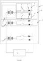
- multiple battery packs 2 may be connected in parallel branches 8.
- the battery system 1 may further be connected in parallel to an external load L to exchange electrical energy with the external load L.
- a battery pack 2 may comprise a plurality of battery cells electrically connected together, preferably in series.
- every branch 8 may be equipped with two diodes 5, 7.
- One diode 5 of the two diodes 5, 7 may be directed to allow charging of the associated battery pack 2, and the other diode 7 of the two diodes 5, 7 may be directed to allow discharging of the associated battery pack 2.
- the diodes are by definition passively controlled switches, whose conduction depends on the voltage drop across them.
- Each individual charging or discharging path in a branch 8 may further be enabled or disabled by an associated controllable switch 4, 6 that is connected in series to the respective diode 5, 7.
- the switches 4, 6 are actively controllable switches that receive respective switching orders from a controller (not represented).
- the controller may be formed as a separate element and located in the vicinity of the battery packs, or delocalised, and/or combined with further control means dedicated to the load.
- the diodes 5, 7 and switches 4, 6 may either be connected to the low side (anode) or the high side (cathode) of battery packs 2.
- Each combination of a controllable switch 4,6 and a series diode 5, 7 acts as an unidirectional switching element 3 that may be actively controlled via the controller.
- the combination of the switches 4,6 and the diodes 5,7 forms as a pair of unidirectional switching elements 3 connected in anti-parallel to each other.
- anti-parallel is meant that the unidirectional switching elements 3 are connected in parallel with each other and that they are oriented in opposite directions.
- the unidirectional switching elements 3 may further be called, based on their orientation, charging switching elements because oriented to allow charging of the associated battery pack or discharging switching elements because oriented to allow discharging of the associated battery pack.
- the combination of a switch 4 and a diode 5 forms a so-called charging switching element oriented to allow the charge (when turned on) and block the discharge of the associated battery pack.
- a switch 6 forms a so-called discharging switching element oriented to allow the discharge (when turned on) and block the charge of the associated battery pack.
- the switches 4, 6 may be of a solid-state type or mechanical type, but are not limited thereto. If an alternative switch is already present for other battery protection functions, this particular alternative switch may also be used to function as a switch 4, 6. Consequently, every battery pack 2 of battery 1 may be set in at least three states: charging, discharging, and bi-directional transfer of power.
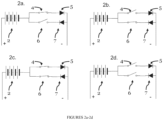
- an "idle state” may be identified as a fourth state. In this idle state, that is shown in Figure 2d , both switches 4 and 6 are kept open to prevent any charging current or discharging current to flow.
- the controller may be configured to control the switches depending on at least one parameter of the external load L and at least one parameter of the battery system.
- the controller may be configured to dynamically limit the load requested by the external load L, i.e. the vehicle, not to exceed the maximum allowable load of the single battery pack.
- the maximum allowable system current I max total of the battery system 1 at any point in time is indeed determined in dependence on the following temporal information for each individual battery pack 2 of the battery 1:
- the lowest battery voltage U min of battery system 1, at which the most restricting battery pack 2 reaches its maximum allowable current (I max ) is calculated using the formula below, wherein "n" is the number of battery packs 2 that are assembled to define the battery system 1:
- U min t max ⁇ OCV 1 t ⁇ Z 1 t ⁇ I 1 , max t ⁇ ⁇ ⁇ ⁇ ⁇ OCV n t ⁇ Z n t ⁇ I n , max t
- a battery management system may be configured to determine and/or calculate at every control cycle the abovementioned parameters OCV, Z, I max , U min , I max total and P battery . These parameters may be derived and/or measured according to known methods in the art based on sensors and/or digital processing means.
- Such a battery management system or controller may be arranged inside the battery system 1, in particular in one or more than one of the battery packs 2.
- One or more than one of the battery packs 2 may serve as a "master" battery pack 2 and comprise a BMS/controller that is also associated with one or more that one "slave” battery packs 2.
- the battery management system or controller may be arranged externally from the battery system 1 and may for example be a controller of an electric external load device, in particular of a vehicle.
- the controller may be a dedicated controller, it may alternatively be integrated in a electronic control unit, "ECU", of the vehicle.
- the maximum allowable battery current (I max total ) and/or the maximum allowable battery power P battery of battery 1, as determined by the BMS may be used to dynamically limit the load requested by the external load, not to exceed the maximum allowable load of the battery system 1.
- the dynamic determination of the maximum allowable battery current (I max total ) and/or the maximum allowable battery power P battery of battery 1 allows optimal use of a battery system 1 that is an assembly of multiple battery packs 2. Any differences in state and history of the individual battery packs 2 is effectively recognized and taken into account.
- An “ideal diode” is a dedicated circuitry configured to mimic a conventional diode without significant losses in high power applications.
- the load requested by the external load may thus be limited according to the above described method.
- the different battery packs 2 may be combined via their switching elements by the controller to suit different needs.
- full discharging may be desired during an active traction state, while allowing some regeneration during regenerative breaking, while full charging may be desired during a recharging operation while the vehicle is connected to a charging station.
- the following modes of operation may then be selected by the controller to meet the load needs:
- During a first mode of operation to provide maximum discharging power, all battery packs 2 may be configured to allow discharging current. Some regeneration may happen during that mode of operation, e.g. during regenerative braking of a vehicle.
- only the highest voltage battery pack may be configured to allow current flow in both directions by applying the bi-directional state shown in Figure 2c to that specific battery pack. If this mode of operation is maintained, once the voltage of the highest voltage battery pack reaches the level of next highest voltage battery pack, two battery packs may discharge in parallel, and so on.
- all battery packs 2 may be configured to allow charging current. Temporarily discharging may be possible for the lowest voltage battery pack 2, configured then to allow current flow in both directions by applying the bi-directional state shown in Figure 2c .
- This mode of operation mimics the first mode of operation but for charging. It allows maximum charging, some discharging and prevents uncontrolled balancing currents in between battery packs.
- multiple battery packs 2 may be set to the bi-directional state shown in Figure 2c .
- the voltage of each battery pack 2 and/or the current provided by each battery pack 2 under load may be checked before setting more than one battery pack 2 to the bi-directional state shown in Figure 2c . If voltage and current differences fall within a pre-defined range a battery pack 2 is allowed to enter the bi-directional state. In this mode, balancing is thus allowed since conditions have been met to allow it safely, namely it was checked that the battery packs are more or less charged in similar manner.
- the controller may be configured to dynamically switch between the charging state of the second mode of operation (shown in Figure 2a ) and the discharging state (shown in Figure 2b ) of the first mode of operation, on each battery pack 2 individually based on demand.
- the following measures can be taken into account:
- program storage devices e.g., digital data storage media, which are machine or computer readable and encode machine-executable or computer-executable programs of instructions, wherein said instructions perform some or all of the steps of said above-described methods.
- the program storage devices may be, e.g., digital memories, magnetic storage media such as a magnetic disks and magnetic tapes, hard drives, or optically readable digital data storage media.
- the embodiments are also intended to cover computers programmed to perform said steps of the above-described methods.
- processors may be provided through the use of dedicated hardware as well as hardware capable of executing software in association with appropriate software.
- the functions may be provided by a single dedicated processor, by a single shared processor, or by a plurality of individual processors, some of which may be shared.
- processor or “controller” should not be construed to refer exclusively to hardware capable of executing software, and may implicitly include, without limitation, digital signal processor (DSP) hardware, network processor, application specific integrated circuit (ASIC), field programmable gate array (FPGA), read only memory (ROM) for storing software, random access memory (RAM), and non-volatile storage. Other hardware, conventional and/or custom, may also be included.
- DSP digital signal processor
- ASIC application specific integrated circuit
- FPGA field programmable gate array
- ROM read only memory
- RAM random access memory
- non-volatile storage non-volatile storage.
- Other hardware conventional and/or custom, may also be included.
- any switches shown in the FIGS. are conceptual only. Their function may be carried out through the operation of program logic, through dedicated logic, through the interaction of program control and dedicated logic, or even manually, the particular technique being selectable by the implementer as more specifically understood from the context.
- any block diagrams herein represent conceptual views of illustrative circuitry embodying the principles of the invention.
- any flow charts, flow diagrams, state transition diagrams, pseudo code, and the like represent various processes which may be substantially represented in computer readable medium and so executed by a computer or processor, whether or not such computer or processor is explicitly shown.
Landscapes
- Engineering & Computer Science (AREA)
- Power Engineering (AREA)
- General Chemical & Material Sciences (AREA)
- Chemical & Material Sciences (AREA)
- Chemical Kinetics & Catalysis (AREA)
- Electrochemistry (AREA)
- Manufacturing & Machinery (AREA)
- Microelectronics & Electronic Packaging (AREA)
- Life Sciences & Earth Sciences (AREA)
- Sustainable Development (AREA)
- Sustainable Energy (AREA)
- Transportation (AREA)
- Mechanical Engineering (AREA)
- Secondary Cells (AREA)
- Charge And Discharge Circuits For Batteries Or The Like (AREA)
Description
- The present invention relates to a battery system comprising a plurality of coupled battery packs and an associated battery management method, a data storage comprising instructions to perform the associated battery management method and a computer program to perform the associated battery management method, in particular for battery systems comprising a plurality of individual battery packs.
- Battery packs are sets of battery cells electrically connected together. Combined together, a plurality of individual battery packs can form battery systems used for a large variety of applications, such as electric vehicles (mobility), but also (temporary) stationary storage, cordless power tools, consumer electronics, etcetera. Typically an electric vehicle may be a car or a two-wheeled vehicle such as a motor scooter, hereafter also named scooter, or motorcycle. Alternatively, the vehicle may also be a trike or a quad. Typically a temporary stationary storage may be an off-grid electric energy storage solution for renewable energies or servers. These applications have further in common that one or more battery packs may be hot-swapped by a user during operation, bringing up the problematic of the connection of multiple battery packs having potentially different charging states, temperatures, use history among others.
- Conventional multi-packs battery systems either apply coupling of the battery packs in series or in parallel. When the battery packs are connected in series the total voltage is increased with each additional battery pack. When the battery packs are connected in parallel, the voltage level is maintained at the voltage level of a single battery pack.
- A connection in series requires a wide operating voltage range of load or a means of transforming the voltage to a more constant level. Both increase complexity and are often impractical.
- A connection in parallel does not have this problem. However to initially couple multiple packs in parallel, the packs are required to be of very close voltage. If this is not the case, a current would flow from one pack to the other with the risks of overcurrent and overheating. To prevent this, the following two known prevention methods have been applied in the prior art alone or in combination. The first known prevention method is active balancing, wherein a controlled current is allowed to flow from one battery pack to another battery pack to mitigate a voltage difference between both battery packs. This causes conversion losses and requires time to happen. The second known prevention method is to only discharge the highest voltage battery pack until the voltage of the first lower voltage battery pack is reached. The battery packs are only coupled once the voltage difference is within a limited predetermined value. This second prevention method also requires a lot of time before battery packs can truly be coupled together. Yet these prior art solutions fail to address the issue of efficiently hot-swapping battery packs in or out of a battery system.
- Moreover, conventional single pack battery systems commonly operate with an allowable system load that is predetermined and static. For battery systems with multiple battery packs, the allowable system load, i.e. the allowable total system current and power is however more difficult to derive. Indeed, the current and power that any battery pack of the plurality of connected battery packs can deliver at a given moment, can change with its state, e.g. temperature, state of charge, use history, etc. When combining multiple battery packs to form a battery system, some of these battery packs may thus be able to provide more current and power than other battery packs due to their state. Furthermore, battery packs that are connected in series or in parallel may not share current equally, due to impedance differences between the individual battery packs and their electrical connections. In combination, these effects result in a combined allowable system current and power which is not equal to the simple sum of the individual battery packs, and changes with the individual states of each of the battery packs of the battery system. Some examples of the relevant prior art are shown in the the following documents:
WO2009111478 ,CN107769280 ,JP4987581 US2013181681 . - An objective of the present invention is to provide a battery system, and a battery management method for a battery system that are improved relative to the prior art and wherein at least one of the above stated problems is obviated or alleviated.
- The present invention is defined by the
independent apparatus claim 1. - Embodiments are based inter alia on the inventive insight that at any time the connection architecture of one or more battery packs in parallel is dynamically adjusted to the set of battery packs and their conditions. In this way the battery management is rendered more resilient and flexible, as it becomes able to cope with swaps, and even hot-swaps, of individual packs without sacrificing security nor operability.
- According to a preferred embodiment, a unidirectional switching element comprises a series combination of an actively controllable switch and a unidirectional passively controlled switch. In this way, the function of a unidirectional switching element may be obtained by combining two simple, commercially available elements, one forcing a direction of current flow, the other one being controllably on or off. Preferably the unidirectional passively controlled switch is a diode, more preferably an ideal diode. In this way, the unidirectionality of flow of the current in the combined unidirectional switching element is insured. The controllable switch may be bidirectional or unidirectional, in which case it should be oriented in the same way as the unidirectional passively controlled switch.
- A a pair of anti-parallel unidirectional switching elements comprises, connected in anti-parallel, a discharging switching element oriented such as to allow the discharge of the associated battery pack and a charging switching element oriented such as to allow the charge of the associated battery pack. In this way, a charging path or a discharging path to a battery pack may be independently controlled. In particular independent control for each direction of power transfer enables to block any undesired cross-balancing between battery packs.
- According to a preferred embodiment, the controller is configured in a first mode of operation to turn on all the discharging switching elements, turn on the charging switching element of the battery pack having the highest voltage and turn off all the other charging switching elements. During this mode of operation, discharging is emphasized, regenerative energy can still be absorbed and safety is insured. It is noted that, in a counter intuitive manner, the battery that is recharged is the battery that needs in theory least recharging. Yet that operation insures that balancing currents from the high voltage battery pack to battery packs with lower voltages are prevented during any intermittent regeneration phase. In this way, operability and safety are prioritized over energy management.
- According to a preferred embodiment, the controller is configured in a second mode of operation to turn on all the charging switching elements, turn on the discharging switching element of the battery pack having the lowest voltage and turn off all the other discharging switching elements. During this mode of operation, charging is emphasized, discharging energy can still be delivered and safety is insured. It is noted that, in a counter intuitive manner, the battery that is discharged is the battery that is the least charged. Yet, that operation insures that balancing currents from that battery pack to battery packs with higher voltages are prevented during any intermittent discharging phase. In this way, operability and safety are prioritized over energy management.
- According to a preferred embodiment, the controller is configured in a third mode of operation to, if voltage and current differences between battery packs fall within a predetermined range, turn on all charging and discharging switching elements. In this mode, balancing between cells is allowed to happen in small proportions. Alternatively, if voltage and current differences between battery packs fall outside of a predetermined range, the controller is configured in a fourth mode of operation to dynamically switch between the first and second mode of operation. Preferably before switching from one mode to the other, all switching elements are first turned off and a disconnected idle state for each battery pack is confirmed. In this way, more flexibility is achieved to cope with varying demands from the load and varying conditions of battery packs.
- According to a further developed embodiment, the controller is configured to operate according to two or more modes of operations, including at least the first mode of operation for optimal discharge of all the battery packs to the external load, the second mode for optimal charge of all battery packs from the external load, the third mode for optimal bidirectional transfer between the battery packs and the external load. In this way, the battery system may cope with frequent (hot-)swapping of battery packs and a varying external load by dynamically switching between modes of operation. It is noted that the external load may be an actual load consuming energy and/or a source generating energy. For instance the external load may be a motor with a traction phase during which the load consumes energy, said motor having also a regeneration phase during which the load provides energy for recharging the battery system. Alternatively the external load may be a pure impedance, for a hand tool for instance, or an ideal source for a charging station.
- According to a preferred embodiment, the battery management controller is configured to dynamically control the switching elements based on one or more than one parameter of the battery system and one or more than one parameter of the external load. Preferably, the one or more than one parameter of the battery system comprises one or more than one parameter for the battery packs, including any one or more of the following: a measured voltage across a battery pack, a measured current flowing through a battery pack, a derived State of Charge (SoC) of a battery pack, an estimated Open Circuit Voltage (OCV), a maximum allowable current (Imax) of a battery pack. Other well-known parameters for describing the energy state of a battery pack may yet be envisaged as well. Preferably, the one or more than one parameter of the external load includes any one or more of the following: a load current request for an electric load, a torque request for a motor, a speed request for a vehicle. Other well-known parameters for describing a use state of the load may yet be envisaged as well.
- The battery management controller is configured to dynamically calculate a maximum allowable current of the battery system based on an estimated impedance for each battery pack, a maximum allowable current for each battery pack, and an estimated open circuit voltage for each battery pack. In this way, the battery system may communicate this important variable to a load management system, to dynamically limit the output request of the load to what the battery system may deliver. This dynamic global Management of the load and the battery system improves the lifetime of the battery. Preferably, the battery management controller is configured to dynamically calculate a maximum allowable current of the battery system using the formula below:


- According to a preferred embodiment, the battery system is configured in use to accommodate the hot-swap of at least one battery pack. By hot-swap is meant the introduction or removal of a battery pack during operation of the battery system. Besides a new battery pack may have any conditions, state of charge, temperature, history. The battery system with its versatile connection architecture is able to cope with one or more hot-swaps and various battery packs in any state.
- According to a preferred embodiment, a vehicle is provided, comprising a battery system according to any of the above preferred embodiments. Preferably the vehicle is one of a car, a motor scooter, a motorcycle, a trike or a quad. Alternatively, a cordless hand tool, a stationary storage may be provided with a battery system according to any of the above preferred embodiments, these alternatives are not covered by the appended claims.
- In this way, several use scenarios may be envisaged, for instance a vehicle with traction and regeneration phases.
- The present invention is further defined by the independent method claim 11.
- In this way, despite varying conditions of the battery packs, a maximum allowable current for the total system is calculated repeatedly every control cycle to update the global status of the battery system. This information is beneficial for any load control in order to improve the battery management.
- According to a preferred embodiment, the method comprises calculating the lowest voltage of the battery system at which the most restricting battery pack reaches its maximum allowable current.
- According to a preferred embodiment, the method further comprises the step of calculating the maximum allowable current of the battery system using the formula below:


- According to the invention there is provided a data storage device encoding a program in machine-readable and machine-executable form to perform one or more steps of any one of the embodiments of the method disclosed above.
- According to the invention, there is provided a computer program comprising computer-executable instructions to perform the method, when the program is run on a computer, according to any one of the steps of any one of the embodiments disclosed above.
- In the following description preferred embodiments of the present invention are further elucidated with reference to the drawings, in which:
-
Figure 1 is an overview of a battery system comprising three battery packs; -
Figure 2a is a detailed schematic view showing a charging state; -
Figure 2b is a detailed schematic view showing a discharging state; -
Figure 2c is a detailed schematic view showing a bi-directional state; and -
Figure 2d is a detailed schematic view showing an idle state. - In the
battery system 1,multiple battery packs 2 may be connected inparallel branches 8. Thebattery system 1 may further be connected in parallel to an external load L to exchange electrical energy with the external load L.A battery pack 2 may comprise a plurality of battery cells electrically connected together, preferably in series. To allow power to flow both to and from eachbattery pack 2, everybranch 8 may be equipped with twodiodes diode 5 of the twodiodes battery pack 2, and theother diode 7 of the twodiodes battery pack 2. The diodes are by definition passively controlled switches, whose conduction depends on the voltage drop across them. Each individual charging or discharging path in abranch 8 may further be enabled or disabled by an associatedcontrollable switch 4, 6 that is connected in series to therespective diode switches 4, 6 are actively controllable switches that receive respective switching orders from a controller (not represented). The controller may be formed as a separate element and located in the vicinity of the battery packs, or delocalised, and/or combined with further control means dedicated to the load. Thediodes controllable switch 4,6 and aseries diode unidirectional switching element 3 that may be actively controlled via the controller. Due to the orientation of the diodes in opposite directions, the combination of theswitches 4,6 and thediodes unidirectional switching elements 3 connected in anti-parallel to each other. By anti-parallel is meant that theunidirectional switching elements 3 are connected in parallel with each other and that they are oriented in opposite directions. Theunidirectional switching elements 3 may further be called, based on their orientation, charging switching elements because oriented to allow charging of the associated battery pack or discharging switching elements because oriented to allow discharging of the associated battery pack. InFigure 1 the combination of aswitch 4 and adiode 5 forms a so-called charging switching element oriented to allow the charge (when turned on) and block the discharge of the associated battery pack. Similarly, the combination of a switch 6 and adiode 7 forms a so-called discharging switching element oriented to allow the discharge (when turned on) and block the charge of the associated battery pack. Theswitches 4, 6 may be of a solid-state type or mechanical type, but are not limited thereto. If an alternative switch is already present for other battery protection functions, this particular alternative switch may also be used to function as aswitch 4, 6. Consequently, everybattery pack 2 ofbattery 1 may be set in at least three states: charging, discharging, and bi-directional transfer of power. - In the charging state shown in
Figure 2a , theswitch 4 is closed to allow charging current to flow throughdiode 5. Switch 6 is kept open to prevent discharging current to flow throughdiode 7. - In the discharging state shown in
Figure 2b , the switch 6 is closed to allow discharging current to flow throughdiode 7.Switch 4 is kept open to prevent charging current to flow throughdiode 5. - In the bi-directional state shown in
Figure 2c , bothswitches 4 and 6 are closed to allow charging current to flow throughdiode 5 and discharging current to flow thoughdiode 7. - In a further preferred embodiment, an "idle state" may be identified as a fourth state. In this idle state, that is shown in
Figure 2d , bothswitches 4 and 6 are kept open to prevent any charging current or discharging current to flow. - The controller may be configured to control the switches depending on at least one parameter of the external load L and at least one parameter of the battery system. Typically to meet security constraints and efficiency constraints, in case of a single battery pack the controller may be configured to dynamically limit the load requested by the external load L, i.e. the vehicle, not to exceed the maximum allowable load of the single battery pack.
- In a more complex battery system with a plurality of battery packs, estimating the maximum allowable system current is a bigger challenge. In particular, applications where battery packs may be hot swapped provide the challenge of combining battery packs with different states of charge, temperatures, and use histories among others. This happens particularly for small vehicle applications (scooter, 3 wheelers) where the mere size of a battery pack makes it possible and necessary for a user to manually remove and replace battery packs in the battery system. For instance, a delivery person using an electric scooter provided with multiple battery packs may in between deliveries swap battery packs to improve his autonomy range.
- The flexible switching architecture of
Figure 1 enables to deal with such a situation. Additionally or alternatively according to another aspect of the invention, a method for estimating this important variable will now be described for also solving the above identified challenge of battery systems with multiple battery packs. - The maximum allowable system current Imax total of the
battery system 1 at any point in time is indeed determined in dependence on the following temporal information for eachindividual battery pack 2 of the battery 1: - the impedance of a battery pack 2 (Z(t)) , which is usually a product of the State of Charge, State of Health and temperature;
- the Open Circuit Voltage (OCV(t)) of a
battery pack 2, which is defined as the voltage of thebattery pack 2 if no current is drawn for some time; and - the maximum allowable current (Imax) of a
battery pack 2, which may be constrained for reasons like safety, lifetime, warranty, etc. - Based on this data, the lowest battery voltage Umin of
battery system 1, at which the most restrictingbattery pack 2 reaches its maximum allowable current (Imax) is calculated using the formula below, wherein "n" is the number ofbattery packs 2 that are assembled to define the battery system 1:
- The resulting lowest battery system voltage Umin of
battery system 1 may then be used to calculate the maximum allowable current (Imax total) of thebattery system 1 using the formula below:
- The maximum allowable battery power Pbattery of
battery system 1 may be the product of the lowest battery voltage Umin ofbattery system 1 and the maximum allowable current (Imax total) ofbattery system 1, defined by the formula:
- Thus, for a
battery 1 that is an assembly of three battery packs, the following formulas may be used:

- A battery management system, "BMS", also referred in the application as battery management controller, may be configured to determine and/or calculate at every control cycle the abovementioned parameters OCV, Z, Imax, Umin, Imax total and Pbattery. These parameters may be derived and/or measured according to known methods in the art based on sensors and/or digital processing means.
- Such a battery management system or controller may be arranged inside the
battery system 1, in particular in one or more than one of the battery packs 2. One or more than one of the battery packs 2 may serve as a "master"battery pack 2 and comprise a BMS/controller that is also associated with one or more that one "slave" battery packs 2. - Alternatively, the battery management system or controller may be arranged externally from the
battery system 1 and may for example be a controller of an electric external load device, in particular of a vehicle. Although the controller may be a dedicated controller, it may alternatively be integrated in a electronic control unit, "ECU", of the vehicle. - The maximum allowable battery current (Imax total) and/or the maximum allowable battery power Pbattery of
battery 1, as determined by the BMS may be used to dynamically limit the load requested by the external load, not to exceed the maximum allowable load of thebattery system 1. - The dynamic determination of the maximum allowable battery current (Imax total) and/or the maximum allowable battery power Pbattery of
battery 1 allows optimal use of abattery system 1 that is an assembly of multiple battery packs 2. Any differences in state and history of the individual battery packs 2 is effectively recognized and taken into account. - It is noted that with the use of conventional diodes comes a voltage loss. This generates heat and negatively affects system performance. To overcome this, an "ideal" diode may be implemented. An "ideal diode" is a dedicated circuitry configured to mimic a conventional diode without significant losses in high power applications.
- The load requested by the external load may thus be limited according to the above described method. Additionally, the
different battery packs 2 may be combined via their switching elements by the controller to suit different needs. In case of an electric vehicle, full discharging may be desired during an active traction state, while allowing some regeneration during regenerative breaking, while full charging may be desired during a recharging operation while the vehicle is connected to a charging station. The following modes of operation may then be selected by the controller to meet the load needs:
During a first mode of operation, to provide maximum discharging power, allbattery packs 2 may be configured to allow discharging current. Some regeneration may happen during that mode of operation, e.g. during regenerative braking of a vehicle. Yet to avoid any uncontrolled cross, balancing, current between battery packs, only the highest voltage battery pack may be configured to allow current flow in both directions by applying the bi-directional state shown inFigure 2c to that specific battery pack. If this mode of operation is maintained, once the voltage of the highest voltage battery pack reaches the level of next highest voltage battery pack, two battery packs may discharge in parallel, and so on. - During a second mode of operation, to provide maximum charging power, all
battery packs 2 may be configured to allow charging current. Temporarily discharging may be possible for the lowestvoltage battery pack 2, configured then to allow current flow in both directions by applying the bi-directional state shown inFigure 2c . This mode of operation mimics the first mode of operation but for charging. It allows maximum charging, some discharging and prevents uncontrolled balancing currents in between battery packs. - During a third mode of operation and to allow more current flow in both directions,
multiple battery packs 2 may be set to the bi-directional state shown inFigure 2c . To make sure no or minimal current flows from onebattery pack 2 to anotherbattery pack 2, the voltage of eachbattery pack 2 and/or the current provided by eachbattery pack 2 under load may be checked before setting more than onebattery pack 2 to the bi-directional state shown inFigure 2c . If voltage and current differences fall within a pre-defined range abattery pack 2 is allowed to enter the bi-directional state. In this mode, balancing is thus allowed since conditions have been met to allow it safely, namely it was checked that the battery packs are more or less charged in similar manner. - During a fourth mode of operation, to allow maximum charging power and discharging power without the voltage and current conditions of the third mode of operation being fulfilled, the controller may be configured to dynamically switch between the charging state of the second mode of operation (shown in
Figure 2a ) and the discharging state (shown inFigure 2b ) of the first mode of operation, on eachbattery pack 2 individually based on demand. To avoid a high cross current between battery packs having different charging conditions to occur the following measures can be taken into account: - a. before switching to the new state all
battery packs 2 shall first go to a disconnected state (idle state shown inFigure 2d ); - b. after confirming all
battery packs 2 have successfully reached the idle state they shall all go into the new state; and - c. these conditions shall preferably be followed for both transitions from charging state to discharging state and vice versa.
- A person skilled in the art would readily recognize that steps of various above-described methods can be performed by programmed computers. Herein, some embodiments are also intended to cover program storage devices, e.g., digital data storage media, which are machine or computer readable and encode machine-executable or computer-executable programs of instructions, wherein said instructions perform some or all of the steps of said above-described methods. The program storage devices may be, e.g., digital memories, magnetic storage media such as a magnetic disks and magnetic tapes, hard drives, or optically readable digital data storage media. The embodiments are also intended to cover computers programmed to perform said steps of the above-described methods.
- The functions of the various elements shown in the figures, including any functional blocks labelled as "processors" or "modules", may be provided through the use of dedicated hardware as well as hardware capable of executing software in association with appropriate software. When provided by a processor, the functions may be provided by a single dedicated processor, by a single shared processor, or by a plurality of individual processors, some of which may be shared. Moreover, explicit use of the term "processor" or "controller" should not be construed to refer exclusively to hardware capable of executing software, and may implicitly include, without limitation, digital signal processor (DSP) hardware, network processor, application specific integrated circuit (ASIC), field programmable gate array (FPGA), read only memory (ROM) for storing software, random access memory (RAM), and non-volatile storage. Other hardware, conventional and/or custom, may also be included. Similarly, any switches shown in the FIGS. are conceptual only. Their function may be carried out through the operation of program logic, through dedicated logic, through the interaction of program control and dedicated logic, or even manually, the particular technique being selectable by the implementer as more specifically understood from the context.
- It should be appreciated by those skilled in the art that any block diagrams herein represent conceptual views of illustrative circuitry embodying the principles of the invention. Similarly, it will be appreciated that any flow charts, flow diagrams, state transition diagrams, pseudo code, and the like represent various processes which may be substantially represented in computer readable medium and so executed by a computer or processor, whether or not such computer or processor is explicitly shown.
- Whilst the principles of the invention have been set out above in connection with specific embodiments, it is understood that this description is merely made by way of example and not as a limitation of the scope of protection which is determined by the appended claims.
Claims (15)
- A battery system (1) for connection to an external load (L) comprising:- a plurality of battery packs (2)- a plurality of unidirectional switching elements (3), and- a battery management controller,- the battery system comprising a plurality of branches (8) connected in parallel to each other, each branch (8) comprising a battery pack (2) connected in series with a pair of unidirectional switching elements (3) connected in anti-parallel, characterized in that the battery management controller is configured to dynamically calculate a maximum allowable current of the battery system based on an estimated impedance for each battery pack, a maximum allowable current for each battery pack, and an estimated open circuit voltage for each battery pack, andthe battery management controller is configured to dynamically control the unidirectional switching elements based on the calculated maximum allowable current of the battery system.
- The battery system of claim 1, wherein the unidirectional switching element (3) comprises a series combination of an actively controllable switch (4, 6) and a unidirectional passively controlled switch (5, 7).
- The battery system of the previous claim, wherein the unidirectional passively controlled switch (5,7) is a diode, more preferably an ideal diode.
- The battery system of any of the above claims, wherein the pair of anti-parallel unidirectional switching elements (3) comprises, connected in anti-parallel, a discharging switching element oriented to allow the discharge and block the charge of the associated battery pack and a charging switching element oriented to allow the charge and block the discharge of the associated battery pack.
- The battery system of the previous claim 4,wherein the controller is configured in a first mode of operation to turn on all the discharging switching elements, turn on the charging switching element of the battery pack having the highest voltage and turn off all the other charging switching elements; and/orwherein the controller is configured in a second mode of operation to turn on all the charging switching elements, turn on the discharging switching element of the battery pack having the lowest voltage and turn off all the other discharging switching elements; and/or wherein the controller is configured in a third mode of operation to, if voltage and current differences between battery packs (2) fall within a predetermined range, turn on all charging and discharging switching elements.
- The battery system of the previous claim 5, wherein the controller is configured in a fourth mode of operation to, if voltage and current differences between battery packs fall outside of a predetermined range, dynamically switch between the first and second mode of operation, wherein preferably before switching from one mode to the other, all switching elements are first turned off and a disconnected idle state for each battery pack is confirmed.
- The battery system of claim 5 or claim 6, wherein the controller is configured to operate according to two or more of the following modes of operation : the first mode of operation for maximum discharge of all the battery packs to the external load, the second mode for maximum charge of all battery packs from the external load, and the third mode for maximum bidirectional transfer between the battery packs and the external load.
- The battery system of any of the above claims, wherein the battery management controller is configured to dynamically control the switching elements based on one or more than one further parameter of the battery system and one or more than one parameter of the external load (L), wherein preferably the one or more than one further parameter of the battery system comprises one or more than one parameter for the battery packs, including any one or more of the following: a measured voltage across a battery pack, a measured current flowing through a battery pack, a derived State of Charge (SoC) of a battery pack, and/or wherein preferably the one or more than one parameter of the external load includes any one or more of the following: a load current request, a torque request, a speed request.
- The battery system of any of the above claims, wherein the battery management controller is configured to dynamically calculate the maximum allowable current of the battery system using the formula below:


- A vehicle, comprising a battery system according to any of the above claims, wherein preferably the vehicle is one of a car, a motor scooter, a motorcycle, a trike or a quad.
- A battery management method for a battery system of a plurality of battery packs according to claim 1, wherein the method comprises the steps of:- receiving an estimated impedance (Zi (t)) for each battery pack, a maximum allowable current (Ii,max ) for each battery pack, and an estimated open circuit voltage (OCV; (t)) for each battery pack,- dynamically calculating a maximum allowable current of the battery system (Imax total (t)) based on the received information, and- managing the plurality of battery packs according to the calculated maximum allowable current of the battery system (Imax total (t)), wherein managing the plurality of battery packs comprises dynamically controlling the unidirectional switching elements based on the calculated maximum allowable current of the battery system.
- A battery management method according to the previous claim, further comprising calculating the lowest voltage of the battery system at which the most restricting battery pack reaches its maximum allowable current (Umin(t)).
- A battery management method according to any of the above method claims, further comprising the step of calculating the maximum allowable current of the battery system using the formula below:


- A data storage device encoding a program in machine-readable and machine-executable form to perform one or more steps of any one of the method claims above.
- A computer program comprising computer-executable instructions to perform a method, when the program is run on a computer, according to any one of the steps of any one of the above method claims.
Applications Claiming Priority (2)
| Application Number | Priority Date | Filing Date | Title |
|---|---|---|---|
| NL2024712 | 2020-01-21 | ||
| PCT/NL2021/050036 WO2021150110A1 (en) | 2020-01-21 | 2021-01-21 | Battery system and battery management method |
Publications (2)
| Publication Number | Publication Date |
|---|---|
| EP4094341A1 EP4094341A1 (en) | 2022-11-30 |
| EP4094341B1 true EP4094341B1 (en) | 2024-03-06 |
Family
ID=74285539
Family Applications (1)
| Application Number | Title | Priority Date | Filing Date |
|---|---|---|---|
| EP21702117.9A Active EP4094341B1 (en) | 2020-01-21 | 2021-01-21 | Battery system and battery management method |
Country Status (3)
| Country | Link |
|---|---|
| EP (1) | EP4094341B1 (en) |
| ES (1) | ES2981212T3 (en) |
| WO (1) | WO2021150110A1 (en) |
Families Citing this family (7)
| Publication number | Priority date | Publication date | Assignee | Title |
|---|---|---|---|---|
| CN114274841B (en) * | 2021-08-09 | 2023-05-23 | 中车资阳机车有限公司 | Parallel direct-hanging control method for multi-branch power battery system |
| CN114784393A (en) * | 2022-04-01 | 2022-07-22 | 天时力(天津)新能源科技有限责任公司 | Battery pack series hot plug connection system based on diode protection |
| CN114872549A (en) * | 2022-05-23 | 2022-08-09 | 三一重工股份有限公司 | Battery unit, power supply and distribution system, power supply and distribution control method and vehicle |
| CN115276181A (en) * | 2022-08-24 | 2022-11-01 | 广州疆海科技有限公司 | Parallel operation control method, device and equipment of battery pack and storage medium |
| CN119305455B (en) * | 2023-07-11 | 2025-10-03 | 广东高域科技有限公司 | Power state control method and flight equipment |
| CN116811666B (en) * | 2023-08-17 | 2024-05-14 | 广州巨湾技研有限公司 | Power battery system discharge control method, system, electronic device and storage medium |
| EP4576486A1 (en) * | 2023-12-21 | 2025-06-25 | Hilti Aktiengesellschaft | Battery pack and battery management system |
Family Cites Families (8)
| Publication number | Priority date | Publication date | Assignee | Title |
|---|---|---|---|---|
| JP4987581B2 (en) * | 2007-06-15 | 2012-07-25 | 日立ビークルエナジー株式会社 | Battery control device |
| WO2009111478A2 (en) * | 2008-03-04 | 2009-09-11 | Adura Systems, Inc. | Machine battery packs and controls |
| JP5683372B2 (en) * | 2011-04-27 | 2015-03-11 | デクセリアルズ株式会社 | Charge / discharge control device, battery pack, electric device, and charge / discharge control method |
| JP6026226B2 (en) * | 2012-10-30 | 2016-11-16 | 株式会社日立情報通信エンジニアリング | Power storage system and power supply system |
| EP2980954B1 (en) * | 2013-03-28 | 2019-12-18 | Murata Manufacturing Co., Ltd. | Power storage device, power storage system, and power storage device control method |
| CN107769280A (en) * | 2016-08-19 | 2018-03-06 | 成都库仑科技有限公司 | A kind of charge-discharge circuit and charge and discharge protecting method, management system and management method based on the circuit |
| CN106451623B (en) * | 2016-10-14 | 2020-07-03 | 宁德时代新能源科技股份有限公司 | Hot-plug method and hot-plug control device, voltage balance method and device |
| JP6794960B2 (en) * | 2017-08-22 | 2020-12-02 | トヨタ自動車株式会社 | Power system |
-
2021
- 2021-01-21 WO PCT/NL2021/050036 patent/WO2021150110A1/en not_active Ceased
- 2021-01-21 EP EP21702117.9A patent/EP4094341B1/en active Active
- 2021-01-21 ES ES21702117T patent/ES2981212T3/en active Active
Also Published As
| Publication number | Publication date |
|---|---|
| ES2981212T3 (en) | 2024-10-07 |
| EP4094341A1 (en) | 2022-11-30 |
| WO2021150110A1 (en) | 2021-07-29 |
Similar Documents
| Publication | Publication Date | Title |
|---|---|---|
| EP4094341B1 (en) | Battery system and battery management method | |
| US10661679B2 (en) | Multiple chemistry battery systems for electric vehicles | |
| EP3521098B1 (en) | Motor-driven vehicle and control method for motor-driven vehicle | |
| EP2908378B1 (en) | Battery system with selective thermal management group | |
| US8330418B2 (en) | Power supply device capable of equalizing electrical properties of batteries | |
| US10836264B2 (en) | Drive system | |
| CN110949154B (en) | charging device | |
| CN110857102A (en) | Autonomous vehicle route planning | |
| KR20190133396A (en) | Power converting apparatus for charging vehicle battery and Method for controlling the same | |
| CN113745701B (en) | Power battery heating method and device, controller and vehicle | |
| CN114335812A (en) | Structure for self-heating of battery | |
| JP7041095B2 (en) | Power system | |
| EP4077021A1 (en) | Method for predicting an electric load imparted on each battery unit in an electric energy storage system | |
| CN110299887B (en) | motor drive system | |
| JP2012050157A (en) | Power storage system | |
| US20250202270A1 (en) | Electrical power converter and program | |
| US12057732B2 (en) | High voltage discharge | |
| JP2016208832A (en) | Battery control apparatus, battery module, battery pack, and battery control method | |
| JP7039520B2 (en) | Power system | |
| CN115303079A (en) | Operator-selected operation of an electric propulsion system with series/parallel voltage sources | |
| JP2016171637A (en) | Power supply system | |
| JP2009189152A (en) | Power supply system, electric vehicle, control method for power supply system, and computer-readable recording medium storing a program for causing computer to execute the control method | |
| JP2010233419A (en) | Motor drive device and electric vehicle | |
| US20170182907A1 (en) | Power control apparatus and power control system | |
| CN115833071B (en) | Multi-motor drive system and feedback energy dissipation method and system thereof |
Legal Events
| Date | Code | Title | Description |
|---|---|---|---|
| STAA | Information on the status of an ep patent application or granted ep patent |
Free format text: STATUS: UNKNOWN |
|
| STAA | Information on the status of an ep patent application or granted ep patent |
Free format text: STATUS: THE INTERNATIONAL PUBLICATION HAS BEEN MADE |
|
| PUAI | Public reference made under article 153(3) epc to a published international application that has entered the european phase |
Free format text: ORIGINAL CODE: 0009012 |
|
| STAA | Information on the status of an ep patent application or granted ep patent |
Free format text: STATUS: REQUEST FOR EXAMINATION WAS MADE |
|
| 17P | Request for examination filed |
Effective date: 20220817 |
|
| AK | Designated contracting states |
Kind code of ref document: A1 Designated state(s): AL AT BE BG CH CY CZ DE DK EE ES FI FR GB GR HR HU IE IS IT LI LT LU LV MC MK MT NL NO PL PT RO RS SE SI SK SM TR |
|
| DAV | Request for validation of the european patent (deleted) | ||
| DAX | Request for extension of the european patent (deleted) | ||
| RIC1 | Information provided on ipc code assigned before grant |
Ipc: H01M 10/44 20060101ALI20230629BHEP Ipc: H01M 10/42 20060101ALI20230629BHEP Ipc: B60L 58/21 20190101ALI20230629BHEP Ipc: H02J 7/00 20060101AFI20230629BHEP |
|
| GRAP | Despatch of communication of intention to grant a patent |
Free format text: ORIGINAL CODE: EPIDOSNIGR1 |
|
| STAA | Information on the status of an ep patent application or granted ep patent |
Free format text: STATUS: GRANT OF PATENT IS INTENDED |
|
| INTG | Intention to grant announced |
Effective date: 20230807 |
|
| GRAS | Grant fee paid |
Free format text: ORIGINAL CODE: EPIDOSNIGR3 |
|
| GRAA | (expected) grant |
Free format text: ORIGINAL CODE: 0009210 |
|
| STAA | Information on the status of an ep patent application or granted ep patent |
Free format text: STATUS: THE PATENT HAS BEEN GRANTED |
|
| AK | Designated contracting states |
Kind code of ref document: B1 Designated state(s): AL AT BE BG CH CY CZ DE DK EE ES FI FR GB GR HR HU IE IS IT LI LT LU LV MC MK MT NL NO PL PT RO RS SE SI SK SM TR |
|
| REG | Reference to a national code |
Ref country code: CH Ref legal event code: EP |
|
| REG | Reference to a national code |
Ref country code: DE Ref legal event code: R096 Ref document number: 602021010107 Country of ref document: DE |
|
| REG | Reference to a national code |
Ref country code: IE Ref legal event code: FG4D |
|
| REG | Reference to a national code |
Ref country code: LT Ref legal event code: MG9D |
|
| PG25 | Lapsed in a contracting state [announced via postgrant information from national office to epo] |
Ref country code: LT Free format text: LAPSE BECAUSE OF FAILURE TO SUBMIT A TRANSLATION OF THE DESCRIPTION OR TO PAY THE FEE WITHIN THE PRESCRIBED TIME-LIMIT Effective date: 20240306 |
|
| PG25 | Lapsed in a contracting state [announced via postgrant information from national office to epo] |
Ref country code: GR Free format text: LAPSE BECAUSE OF FAILURE TO SUBMIT A TRANSLATION OF THE DESCRIPTION OR TO PAY THE FEE WITHIN THE PRESCRIBED TIME-LIMIT Effective date: 20240607 |
|
| PG25 | Lapsed in a contracting state [announced via postgrant information from national office to epo] |
Ref country code: RS Free format text: LAPSE BECAUSE OF FAILURE TO SUBMIT A TRANSLATION OF THE DESCRIPTION OR TO PAY THE FEE WITHIN THE PRESCRIBED TIME-LIMIT Effective date: 20240606 Ref country code: HR Free format text: LAPSE BECAUSE OF FAILURE TO SUBMIT A TRANSLATION OF THE DESCRIPTION OR TO PAY THE FEE WITHIN THE PRESCRIBED TIME-LIMIT Effective date: 20240306 |
|
| REG | Reference to a national code |
Ref country code: NL Ref legal event code: FP |
|
| PG25 | Lapsed in a contracting state [announced via postgrant information from national office to epo] |
Ref country code: RS Free format text: LAPSE BECAUSE OF FAILURE TO SUBMIT A TRANSLATION OF THE DESCRIPTION OR TO PAY THE FEE WITHIN THE PRESCRIBED TIME-LIMIT Effective date: 20240606 Ref country code: NO Free format text: LAPSE BECAUSE OF FAILURE TO SUBMIT A TRANSLATION OF THE DESCRIPTION OR TO PAY THE FEE WITHIN THE PRESCRIBED TIME-LIMIT Effective date: 20240606 Ref country code: LT Free format text: LAPSE BECAUSE OF FAILURE TO SUBMIT A TRANSLATION OF THE DESCRIPTION OR TO PAY THE FEE WITHIN THE PRESCRIBED TIME-LIMIT Effective date: 20240306 Ref country code: HR Free format text: LAPSE BECAUSE OF FAILURE TO SUBMIT A TRANSLATION OF THE DESCRIPTION OR TO PAY THE FEE WITHIN THE PRESCRIBED TIME-LIMIT Effective date: 20240306 Ref country code: GR Free format text: LAPSE BECAUSE OF FAILURE TO SUBMIT A TRANSLATION OF THE DESCRIPTION OR TO PAY THE FEE WITHIN THE PRESCRIBED TIME-LIMIT Effective date: 20240607 Ref country code: FI Free format text: LAPSE BECAUSE OF FAILURE TO SUBMIT A TRANSLATION OF THE DESCRIPTION OR TO PAY THE FEE WITHIN THE PRESCRIBED TIME-LIMIT Effective date: 20240306 Ref country code: BG Free format text: LAPSE BECAUSE OF FAILURE TO SUBMIT A TRANSLATION OF THE DESCRIPTION OR TO PAY THE FEE WITHIN THE PRESCRIBED TIME-LIMIT Effective date: 20240306 |
|
| REG | Reference to a national code |
Ref country code: AT Ref legal event code: MK05 Ref document number: 1664495 Country of ref document: AT Kind code of ref document: T Effective date: 20240306 |
|
| PG25 | Lapsed in a contracting state [announced via postgrant information from national office to epo] |
Ref country code: SE Free format text: LAPSE BECAUSE OF FAILURE TO SUBMIT A TRANSLATION OF THE DESCRIPTION OR TO PAY THE FEE WITHIN THE PRESCRIBED TIME-LIMIT Effective date: 20240306 Ref country code: LV Free format text: LAPSE BECAUSE OF FAILURE TO SUBMIT A TRANSLATION OF THE DESCRIPTION OR TO PAY THE FEE WITHIN THE PRESCRIBED TIME-LIMIT Effective date: 20240306 |
|
| PG25 | Lapsed in a contracting state [announced via postgrant information from national office to epo] |
Ref country code: IS Free format text: LAPSE BECAUSE OF FAILURE TO SUBMIT A TRANSLATION OF THE DESCRIPTION OR TO PAY THE FEE WITHIN THE PRESCRIBED TIME-LIMIT Effective date: 20240706 |
|
| REG | Reference to a national code |
Ref country code: ES Ref legal event code: FG2A Ref document number: 2981212 Country of ref document: ES Kind code of ref document: T3 Effective date: 20241007 |
|
| PG25 | Lapsed in a contracting state [announced via postgrant information from national office to epo] |
Ref country code: SM Free format text: LAPSE BECAUSE OF FAILURE TO SUBMIT A TRANSLATION OF THE DESCRIPTION OR TO PAY THE FEE WITHIN THE PRESCRIBED TIME-LIMIT Effective date: 20240306 Ref country code: PT Free format text: LAPSE BECAUSE OF FAILURE TO SUBMIT A TRANSLATION OF THE DESCRIPTION OR TO PAY THE FEE WITHIN THE PRESCRIBED TIME-LIMIT Effective date: 20240708 |
|
| PG25 | Lapsed in a contracting state [announced via postgrant information from national office to epo] |
Ref country code: CZ Free format text: LAPSE BECAUSE OF FAILURE TO SUBMIT A TRANSLATION OF THE DESCRIPTION OR TO PAY THE FEE WITHIN THE PRESCRIBED TIME-LIMIT Effective date: 20240306 Ref country code: EE Free format text: LAPSE BECAUSE OF FAILURE TO SUBMIT A TRANSLATION OF THE DESCRIPTION OR TO PAY THE FEE WITHIN THE PRESCRIBED TIME-LIMIT Effective date: 20240306 |
|
| PG25 | Lapsed in a contracting state [announced via postgrant information from national office to epo] |
Ref country code: AT Free format text: LAPSE BECAUSE OF FAILURE TO SUBMIT A TRANSLATION OF THE DESCRIPTION OR TO PAY THE FEE WITHIN THE PRESCRIBED TIME-LIMIT Effective date: 20240306 |
|
| PG25 | Lapsed in a contracting state [announced via postgrant information from national office to epo] |
Ref country code: PL Free format text: LAPSE BECAUSE OF FAILURE TO SUBMIT A TRANSLATION OF THE DESCRIPTION OR TO PAY THE FEE WITHIN THE PRESCRIBED TIME-LIMIT Effective date: 20240306 |
|
| PG25 | Lapsed in a contracting state [announced via postgrant information from national office to epo] |
Ref country code: SK Free format text: LAPSE BECAUSE OF FAILURE TO SUBMIT A TRANSLATION OF THE DESCRIPTION OR TO PAY THE FEE WITHIN THE PRESCRIBED TIME-LIMIT Effective date: 20240306 |
|
| PG25 | Lapsed in a contracting state [announced via postgrant information from national office to epo] |
Ref country code: SM Free format text: LAPSE BECAUSE OF FAILURE TO SUBMIT A TRANSLATION OF THE DESCRIPTION OR TO PAY THE FEE WITHIN THE PRESCRIBED TIME-LIMIT Effective date: 20240306 Ref country code: SK Free format text: LAPSE BECAUSE OF FAILURE TO SUBMIT A TRANSLATION OF THE DESCRIPTION OR TO PAY THE FEE WITHIN THE PRESCRIBED TIME-LIMIT Effective date: 20240306 Ref country code: RO Free format text: LAPSE BECAUSE OF FAILURE TO SUBMIT A TRANSLATION OF THE DESCRIPTION OR TO PAY THE FEE WITHIN THE PRESCRIBED TIME-LIMIT Effective date: 20240306 Ref country code: PT Free format text: LAPSE BECAUSE OF FAILURE TO SUBMIT A TRANSLATION OF THE DESCRIPTION OR TO PAY THE FEE WITHIN THE PRESCRIBED TIME-LIMIT Effective date: 20240708 Ref country code: PL Free format text: LAPSE BECAUSE OF FAILURE TO SUBMIT A TRANSLATION OF THE DESCRIPTION OR TO PAY THE FEE WITHIN THE PRESCRIBED TIME-LIMIT Effective date: 20240306 Ref country code: IS Free format text: LAPSE BECAUSE OF FAILURE TO SUBMIT A TRANSLATION OF THE DESCRIPTION OR TO PAY THE FEE WITHIN THE PRESCRIBED TIME-LIMIT Effective date: 20240706 Ref country code: EE Free format text: LAPSE BECAUSE OF FAILURE TO SUBMIT A TRANSLATION OF THE DESCRIPTION OR TO PAY THE FEE WITHIN THE PRESCRIBED TIME-LIMIT Effective date: 20240306 Ref country code: CZ Free format text: LAPSE BECAUSE OF FAILURE TO SUBMIT A TRANSLATION OF THE DESCRIPTION OR TO PAY THE FEE WITHIN THE PRESCRIBED TIME-LIMIT Effective date: 20240306 Ref country code: AT Free format text: LAPSE BECAUSE OF FAILURE TO SUBMIT A TRANSLATION OF THE DESCRIPTION OR TO PAY THE FEE WITHIN THE PRESCRIBED TIME-LIMIT Effective date: 20240306 |
|
| REG | Reference to a national code |
Ref country code: DE Ref legal event code: R097 Ref document number: 602021010107 Country of ref document: DE |
|
| PLBE | No opposition filed within time limit |
Free format text: ORIGINAL CODE: 0009261 |
|
| STAA | Information on the status of an ep patent application or granted ep patent |
Free format text: STATUS: NO OPPOSITION FILED WITHIN TIME LIMIT |
|
| PG25 | Lapsed in a contracting state [announced via postgrant information from national office to epo] |
Ref country code: DK Free format text: LAPSE BECAUSE OF FAILURE TO SUBMIT A TRANSLATION OF THE DESCRIPTION OR TO PAY THE FEE WITHIN THE PRESCRIBED TIME-LIMIT Effective date: 20240306 |
|
| PG25 | Lapsed in a contracting state [announced via postgrant information from national office to epo] |
Ref country code: DK Free format text: LAPSE BECAUSE OF FAILURE TO SUBMIT A TRANSLATION OF THE DESCRIPTION OR TO PAY THE FEE WITHIN THE PRESCRIBED TIME-LIMIT Effective date: 20240306 |
|
| 26N | No opposition filed |
Effective date: 20241209 |
|
| PGFP | Annual fee paid to national office [announced via postgrant information from national office to epo] |
Ref country code: NL Payment date: 20250127 Year of fee payment: 5 |
|
| PGFP | Annual fee paid to national office [announced via postgrant information from national office to epo] |
Ref country code: DE Payment date: 20250129 Year of fee payment: 5 |
|
| PGFP | Annual fee paid to national office [announced via postgrant information from national office to epo] |
Ref country code: ES Payment date: 20250203 Year of fee payment: 5 |
|
| PG25 | Lapsed in a contracting state [announced via postgrant information from national office to epo] |
Ref country code: SI Free format text: LAPSE BECAUSE OF FAILURE TO SUBMIT A TRANSLATION OF THE DESCRIPTION OR TO PAY THE FEE WITHIN THE PRESCRIBED TIME-LIMIT Effective date: 20240306 |
|
| PGFP | Annual fee paid to national office [announced via postgrant information from national office to epo] |
Ref country code: FR Payment date: 20250127 Year of fee payment: 5 |
|
| PGFP | Annual fee paid to national office [announced via postgrant information from national office to epo] |
Ref country code: IT Payment date: 20250121 Year of fee payment: 5 Ref country code: GB Payment date: 20250127 Year of fee payment: 5 |
|
| REG | Reference to a national code |
Ref country code: CH Ref legal event code: PL |
|
| PG25 | Lapsed in a contracting state [announced via postgrant information from national office to epo] |
Ref country code: MC Free format text: LAPSE BECAUSE OF FAILURE TO SUBMIT A TRANSLATION OF THE DESCRIPTION OR TO PAY THE FEE WITHIN THE PRESCRIBED TIME-LIMIT Effective date: 20240306 Ref country code: LU Free format text: LAPSE BECAUSE OF NON-PAYMENT OF DUE FEES Effective date: 20250121 |
|
| PG25 | Lapsed in a contracting state [announced via postgrant information from national office to epo] |
Ref country code: BE Free format text: LAPSE BECAUSE OF NON-PAYMENT OF DUE FEES Effective date: 20250131 |
|
| PG25 | Lapsed in a contracting state [announced via postgrant information from national office to epo] |
Ref country code: CH Free format text: LAPSE BECAUSE OF NON-PAYMENT OF DUE FEES Effective date: 20250131 |
|
| REG | Reference to a national code |
Ref country code: BE Ref legal event code: MM Effective date: 20250131 |
|
| PG25 | Lapsed in a contracting state [announced via postgrant information from national office to epo] |
Ref country code: IE Free format text: LAPSE BECAUSE OF NON-PAYMENT OF DUE FEES Effective date: 20250121 |