EP4094177B1 - System and method for fatigue response prediction - Google Patents
System and method for fatigue response prediction Download PDFInfo
- Publication number
- EP4094177B1 EP4094177B1 EP20713469.3A EP20713469A EP4094177B1 EP 4094177 B1 EP4094177 B1 EP 4094177B1 EP 20713469 A EP20713469 A EP 20713469A EP 4094177 B1 EP4094177 B1 EP 4094177B1
- Authority
- EP
- European Patent Office
- Prior art keywords
- virtual surface
- surface profile
- model
- profile
- roughness parameters
- Prior art date
- Legal status (The legal status is an assumption and is not a legal conclusion. Google has not performed a legal analysis and makes no representation as to the accuracy of the status listed.)
- Active
Links
Images

Classifications
-
- G—PHYSICS
- G06—COMPUTING OR CALCULATING; COUNTING
- G06F—ELECTRIC DIGITAL DATA PROCESSING
- G06F30/00—Computer-aided design [CAD]
- G06F30/20—Design optimisation, verification or simulation
- G06F30/27—Design optimisation, verification or simulation using machine learning, e.g. artificial intelligence, neural networks, support vector machines [SVM] or training a model
-
- G—PHYSICS
- G06—COMPUTING OR CALCULATING; COUNTING
- G06F—ELECTRIC DIGITAL DATA PROCESSING
- G06F30/00—Computer-aided design [CAD]
- G06F30/20—Design optimisation, verification or simulation
- G06F30/23—Design optimisation, verification or simulation using finite element methods [FEM] or finite difference methods [FDM]
-
- G—PHYSICS
- G06—COMPUTING OR CALCULATING; COUNTING
- G06F—ELECTRIC DIGITAL DATA PROCESSING
- G06F9/00—Arrangements for program control, e.g. control units
- G06F9/06—Arrangements for program control, e.g. control units using stored programs, i.e. using an internal store of processing equipment to receive or retain programs
- G06F9/44—Arrangements for executing specific programs
- G06F9/455—Emulation; Interpretation; Software simulation, e.g. virtualisation or emulation of application or operating system execution engines
-
- G—PHYSICS
- G06—COMPUTING OR CALCULATING; COUNTING
- G06N—COMPUTING ARRANGEMENTS BASED ON SPECIFIC COMPUTATIONAL MODELS
- G06N3/00—Computing arrangements based on biological models
- G06N3/02—Neural networks
- G06N3/04—Architecture, e.g. interconnection topology
- G06N3/047—Probabilistic or stochastic networks
-
- G—PHYSICS
- G06—COMPUTING OR CALCULATING; COUNTING
- G06N—COMPUTING ARRANGEMENTS BASED ON SPECIFIC COMPUTATIONAL MODELS
- G06N3/00—Computing arrangements based on biological models
- G06N3/02—Neural networks
- G06N3/04—Architecture, e.g. interconnection topology
- G06N3/0475—Generative networks
-
- G—PHYSICS
- G06—COMPUTING OR CALCULATING; COUNTING
- G06N—COMPUTING ARRANGEMENTS BASED ON SPECIFIC COMPUTATIONAL MODELS
- G06N3/00—Computing arrangements based on biological models
- G06N3/02—Neural networks
- G06N3/08—Learning methods
-
- G—PHYSICS
- G06—COMPUTING OR CALCULATING; COUNTING
- G06N—COMPUTING ARRANGEMENTS BASED ON SPECIFIC COMPUTATIONAL MODELS
- G06N3/00—Computing arrangements based on biological models
- G06N3/02—Neural networks
- G06N3/08—Learning methods
- G06N3/09—Supervised learning
-
- G—PHYSICS
- G06—COMPUTING OR CALCULATING; COUNTING
- G06N—COMPUTING ARRANGEMENTS BASED ON SPECIFIC COMPUTATIONAL MODELS
- G06N3/00—Computing arrangements based on biological models
- G06N3/02—Neural networks
- G06N3/08—Learning methods
- G06N3/094—Adversarial learning
-
- G—PHYSICS
- G01—MEASURING; TESTING
- G01N—INVESTIGATING OR ANALYSING MATERIALS BY DETERMINING THEIR CHEMICAL OR PHYSICAL PROPERTIES
- G01N33/00—Investigating or analysing materials by specific methods not covered by groups G01N1/00 - G01N31/00
- G01N33/20—Metals
- G01N33/204—Structure thereof, e.g. crystal structure
- G01N33/2045—Defects
-
- G—PHYSICS
- G06—COMPUTING OR CALCULATING; COUNTING
- G06F—ELECTRIC DIGITAL DATA PROCESSING
- G06F2119/00—Details relating to the type or aim of the analysis or the optimisation
- G06F2119/04—Ageing analysis or optimisation against ageing
-
- G—PHYSICS
- G06—COMPUTING OR CALCULATING; COUNTING
- G06N—COMPUTING ARRANGEMENTS BASED ON SPECIFIC COMPUTATIONAL MODELS
- G06N3/00—Computing arrangements based on biological models
- G06N3/02—Neural networks
- G06N3/04—Architecture, e.g. interconnection topology
- G06N3/045—Combinations of networks
Definitions
- the present disclosure relates, in general, to the field of material fatigue response prediction.
- Embodiments of the present disclosure are applicable, for example, for predicting fatigue life of additively manufactured parts from surface roughness parameters.
- AM additive manufacturing
- Surface quality of a part may have a significant impact on the fatigue life of the part.
- Surface preparation and machining techniques that reduce surface roughness have been successfully employed to extend fatigue lives of parts that are subjected to cyclic stresses. While such methods may be applicable generally to external surfaces of additively manufactured parts, the internal "as-built" surfaces of complex geometry parts may prove more challenging to modify.
- Patent document US 2018/113967 A1 (AGRAWAL ANKIT [US] ET AL) 26 April 2018 (2018-04-26) pertains to the prediction of fatigue strength of steel alloys comprising deriving data like steel fatigue from material databases.
- aspects of the present disclosure are directed to techniques for prediction of fatigue response based on surface roughness that address at least some of the technical challenges mentioned above.
- a computer-implemented method for predicting a fatigue response of a material.
- the method comprises receiving a user input specifying one or more surface roughness parameters that characterize a surface of a material for which fatigue life is to be predicted.
- the method further comprises generating at least one realistic virtual surface profile from the specified one or more surface roughness parameters.
- the method further comprises predicting fatigue life of the material in dependence of a stress field applied to the generated virtual surface profile.
- the virtual surface profile may be generated utilizing machine learning based generative models, frequency pattern matching, Autoregressive Moving Average (ARMA) models, or combinations thereof.
- the prediction of the fatigue life may be carried out utilizing finite element analysis based simulations, machine learning methods, or combinations thereof.
- aspects of the present disclosure relate to prediction of fatigue response based on surface roughness.
- Surface roughness is generally poor for parts fabricated by additive manufacturing (AM), which may significantly affect the fatigue performance of such parts.
- AM additive manufacturing
- To assess surface roughness one can perform surface height measurements, which may be expensive to perform and/or not accessible to all users.
- To assess the fatigue life of a part a known approach is to not only quantify the surface roughness, but also generate a huge database of fatigue data corresponding to the different surface conditions. Generating such database currently is done through experiments, meaning that a large number of test specimens need to be manufactured with different surface conditions and then tested. Such an experimental campaign may be time consuming and expensive. Moreover, one needs to repeat it for different AM machines, process settings and powders.
- An alternative to the experimental approach is to predict the effect of surface roughness on fatigue life through simulation techniques. However, such techniques may be computationally intensive and time consuming. Furthermore, such techniques also require surface measurements, which may be difficult and expensive to perform.
- the techniques disclosed herein address at least the above described problems by automatically generating a realistic virtual surface profile based on user-specified surface roughness parameters and predicting the corresponding fatigue property in dependence of a stress field applied to the virtual surface profile.
- the proposed techniques rely on finite element analyses (FEA), advanced machine learning (ML) methods, or combinations thereof. Using the proposed techniques, one can obtain in an efficient numerical way the fatigue property corresponding to any user defined surface roughness parameters, thereby avoiding expensive and time-consuming experimental methods.
- Aspects of present disclosure may be embodied in a computer-aided engineering (CAE) or computer-aided manufacturing (CAM) package.
- CAE computer-aided engineering
- CAM computer-aided manufacturing
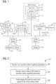
- the computing system 100 can be an electronic, computer framework comprising and/or employing any number and combination of computing devices and networks utilizing various communication technologies.
- the computing system 100 may be easily scalable, extensible, and modular, with the ability to change to different services or reconfigure some features independently of others.
- the computing system 100 may be, for example, a server, desktop computer, laptop computer, tablet computer, or smartphone.
- computing system 100 may be a cloud computing node.
- Computing system 100 may be described in the general context of computer executable instructions, such as program modules, being executed by a computing system.
- program modules may include routines, programs, objects, components, logic, data structures, and so on that perform particular tasks or implement particular abstract data types.
- Computing system 100 may be practiced in distributed cloud computing environments where tasks are performed by remote processing devices that are linked through a communications network.
- program modules may be located in both local and remote computing system storage media including memory storage devices.
- the computing system 100 has one or more processors 102, which may include, for example, one or more central processing units (CPU), graphics processing units (GPU), or any other processor known in the art.
- the processors 102 can be a single-core processor, multi-core processor, computing cluster, or any number of other configurations.
- the processors 102 also referred to as processing circuits, are coupled via a system bus 104 to a system memory 106 and various other components.
- the system memory 106 can include a read only memory or ROM 108 and a random access memory or RAM 110.
- the ROM 108 is coupled to the system bus 104 and may include a basic input/output system (BIOS), which controls certain basic functions of the computing system 100.
- BIOS basic input/output system
- the RAM 110 is read-write memory coupled to the system bus 104 for use by the processors 102.
- the system memory 106 provides temporary memory space for operations of said instructions during operation.
- the system memory 106 can include random access memory (RAM), read only memory, flash memory, or any other suitable memory systems.
- the computing system 100 comprises an I/O adapter 112 (input/output adapter) and a communications adapter 114 coupled to the system bus 104.
- the I/O adapter 112 may be a small computer system interface (SCSI) adapter that communicates with a hard disk 116 and/or any other similar component.
- SCSI small computer system interface
- the I/O adapter 112 and the hard disk 116 are collectively referred to herein as a mass storage 118.
- the mass storage 118 is an example of a tangible storage medium readable by the processors 102, where the software 120 is stored as instructions for execution by the processors 102 to cause the computing system 100 to operate, such as is described herein below with respect to the various figures. Examples of computer program product and the execution of such instruction is discussed herein in more detail.
- the communications adapter 114 interconnects the system bus 104 with a network 122, which may be an outside network, enabling the computing system 100 to communicate with other such systems.
- a portion of the system memory 106 and the mass storage 118 collectively store an operating system, which may be any appropriate operating system, to coordinate the functions of the various components shown in FIG. 1 .
- Additional input/output devices are shown as connected to the system bus 104 via a display adapter 124 and an interface adapter 126.
- the I/O adapter 112, the communications adapter 114, the display adapter 124 and the interface adapter 126 may be connected to one or more I/O buses that are connected to the system bus 104 via an intermediate bus bridge (not shown).
- a display 128 e.g., a screen or a display monitor
- the display adapter 124 which may include a graphics controller to improve the performance of graphics intensive applications and a video controller.
- Suitable I/O buses for connecting peripheral devices such as hard disk controllers, network adapters, and graphics adapters typically include common protocols, such as the Peripheral Component Interconnect (PCI).
- PCI Peripheral Component Interconnect
- the computing system 100 includes processing capability in the form of the processors 102, and, storage capability including the system memory 106 and the mass storage 118, input means such as the keyboard 130 and the mouse 132, and output capability including the display 128.
- the communications adapter 114 can transmit data using any suitable interface or protocol, such as the internet small computing system interface, among others.
- the network 122 may be a cellular network, a radio network, a wide area network (WAN), a local area network (LAN), or the Internet, among others.
- An external computing device may connect to the computing system 100 through the network 122.
- an external computing device may be an external webserver or a cloud computing node.
- FIG. 1 the block diagram of FIG. 1 is not intended to indicate that the computing system 100 is to include all of the components shown in FIG. 1 . Rather, the computing system 100 can include any appropriate fewer or additional components not illustrated in FIG. 1 (e.g., additional memory components, embedded controllers, modules, additional network interfaces, etc.). Further, the embodiments described herein with respect to computing system 100 may be implemented with any appropriate logic, wherein the logic, as referred to herein, can include any suitable hardware (e.g., a processor, an embedded controller, or an application specific integrated circuit, among others), software (e.g., an application, among others), firmware, or any suitable combination of hardware, software, and firmware, in various embodiments.
- suitable hardware e.g., a processor, an embedded controller, or an application specific integrated circuit, among others
- software e.g., an application, among others
- firmware e.g., an application, among others
- FIG. 2 illustrates a method 200 for predicting a fatigue response of a material according to an aspect of the present disclosure.
- the method 200 may be implemented, for example, in conjunction with the computing system 100 illustrated in FIG. 1 .
- Block 202 of the method 200 involves receiving a user input specifying values of one or more surface roughness parameters.
- the user may provide input on one or more roughness parameters that are typically used to characterize the surface of the material for which fatigue life is to be predicted.
- the one or more parameters may be selected, for example, from the non-limiting examples of surface roughness parameters provided below. It is to be appreciated that the disclosed techniques may be used to account for additional or different parameters.
- FIG. 3 shows an illustrative one-dimensional (1D) surface curve 300 defining a surface having microscopic asperities, where the axis 302 represents a distance across the surface (x) and the axis y represents asperity height (y).
- the surface roughness parameters can be defined as:
- block 204 of the method 200 involves generating at least one realistic virtual surface profile from the specified one or more surface roughness parameters.
- a "virtual surface profile” refers to a machine generated surface profile obtained from user-specified surface roughness parameter values using a data-driven generative method.
- a virtual surface profile is an artificial surface profile, and is not to be construed as being generated from surface measurements of a real surface.
- a virtual surface may be generated to closely resemble real surface profiles in an available data set. Accordingly, such a virtual surface profile is also described as being "realistic", while not being real.
- Example embodiments data-driven approaches for generating virtual surface profiles are illustrated below referring to FIG. 4-6 .
- block 206 of the method 200 involves predicting fatigue life of the material based on a stress field applied to the generated virtual surface profile. This may comprise generating a stress-life (S-N curve) plotting cyclic stress amplitude S against fatigue life N f defined by number of cycles to failure.
- the generated S-N curve may be graphically displayed on a display screen. Exemplary non-limiting implementations within the scope of the above-described method 200 are illustrated below referring to FIG. 7-9 .
- FIG. 4 illustrates a first example method 400 for generating one or more virtual surface profiles based on the user-specified surface roughness parameters.
- the method 400 utilizes a machine learning based generative model. Examples of such models include Generative Adversarial Networks (GAN), Variational Auto-Encoders, or their variations (e.g. WGAN-GP), among others.
- GAN Generative Adversarial Networks
- WGAN-GP Variational Auto-Encoders
- the generative model may be trained on the available data and utilized to generate novel virtual surface profiles that resemble the surface profiles in the available data.
- the method 400 utilizes a GAN.
- Block 402 of the method 400 involves obtaining, as training data, 1D surface profiles s from surface measurements and calculated roughness parameters r of a plurality of real surfaces.
- the data from real surfaces may be pre-processed, which may, for example, involve the steps of resampling the data to obtain same sampling rate throughout all the samples, splitting the data to obtain the same sample length, detrending, etc.
- Block 404 of the method 400 involves training the generative model using the training data obtained at block 402.
- s ⁇ G( z , r ) are the generated 1D surface profiles, as function of the generator G, z is latent vector and R i (*) is the function that represents the roughness parameters i .
- the objective function E is summed over the number of surface roughness parameters specified, which in this case is 9.
- Block 408 of the method 400 involves the generation of a specified number of new (virtual) 1D surface profiles s ⁇ , that closely resemble the surface profiles s in the training data, based on the modified objective function of the generative model.
- the generated virtual 1D surface profile may be smoothed to reduce sharp peaks, for example, using spectral or spline interpolation.
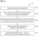
- FIG. 5 illustrates a second example method 500 for generating one or more virtual surface profiles based on the user-specified surface roughness parameters.
- the method 500 uses an Autoregressive Moving Average (ARMA) model to generate new surface profiles.
- ARMA Autoregressive Moving Average
- the basic principle of this approach is to identify a suitable mathematical model describing the surface height profile from the available data and using the same model to generate new surface profiles.
- Block 502 of the method 500 involves obtaining surface profiles from available data.
- the available data comprises surface profiles obtained from surface measurements and calculated roughness parameters of a plurality of real surfaces.
- the data from real surfaces may be pre-processed, which may, for example, involve the steps of resampling the data to obtain same sampling rate throughout all the samples, splitting the data to obtain the same sample length, detrending, etc.
- Block 504 of the method 500 involves choosing datasets having surface roughness parameters R that are already close to the user-specified surface roughness parameters R*.
- Block 506 of the method of the method 500 involves determining a mathematical model of the following form from the chosen dataset.
- y t denotes the surface height at spatial position x t and the coefficients a i and b j determine the autoregressive (AR) and moving average (MA) part of the model, respectively.
- ⁇ t denotes white noise, i.e. a random input with mean zero and fixed variance ⁇ 2 , at position x t .
- model parameters are determined from the chosen dataset, namely order of the AR and MA contribution p, q, coefficients of the AR and MA contribution a 1 , ..., a p , b 1 , ..., b q and variation of the input noise ⁇ 2 .
- these quantities may be identified using, for example, a Box-Jenkins approach in combination with a minimization of Akaike's Information Criterion (AIC).
- AIC Akaike's Information Criterion
- the Box-Jenkins approach is discussed in the publication: Box, George, & Jenkins, Gwilym (1970). Time Series Analysis: Forecasting and Control. San Francisco: Holden-Day .
- AIC Akaike's Information Criterion
- the aforementioned model parameters may be obtained by averaging the corresponding results from all datasets.
- the result is an ARMA model describing the spatial evolution of the surface height profile.
- Block 508 of the method 500 involves obtaining one or more new surface profiles z using the ARMA model developed in block 506.
- the new surface profile z would have surface roughness parameter parameters Rz, where Rz ⁇ R*.
- a virtual surface z* is generated which would have the user-specified surface roughness parameter R*.
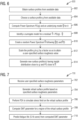
- FIG. 6 illustrates a third example method 600 for generating one or more virtual surface profiles based on the user-specified surface roughness parameters. While the method 500 shown in FIG. 5 works directly on the height data of the surface profiles, the method 600 shown in FIG. 6 identifies typical surface height frequency patterns from available data and creating new (virtual) surface profiles based on those patterns.
- Block 602 of the example method 600 involves obtaining surface profiles from available data.
- the available data comprises surface profiles obtained from surface measurements and calculated roughness parameters of a plurality of real surfaces.
- the data from real surfaces may be pre-processed, which may, for example, involve the steps of resampling the data to obtain same sampling rate throughout all the samples, splitting the data to obtain the same sample length, detrending, etc.
- Block 604 of the method 600 involves choosing a surface profile g from the available data. A particular strategy for the choice is presented at block 612.
- Block 606 of the method 600 involves computing a Power Spectrum (PS) of g , namely, PS ( g ), and an underlying model ⁇ for it via the nonlinear least squares (NLS) method. It has been observed that the following parameterized model presents a good candidate.
- PS Power Spectrum
- NLS nonlinear least squares
- the parameters a, b, c, ⁇ may be identified by NLS.
- r ⁇ is normally distributed with variance decaying exponentially for increasing frequencies. This is due to the fact that such frequencies larger than a certain threshold value are essentially non-existent. This decay motivates a model of the form r ⁇ f ⁇ N 0 , ⁇ r ⁇ f 2
- Block 610 of the method 600 involves creating a random Power Spectrum ⁇ following the trend ⁇ ( f ) and a noise term r ⁇ ( f ) from above-mentioned distribution.
- the generated surface profile will eventually have a PS close to ⁇ .
- the surface g should be chosen as the one having a roughness value that is closest to the desired surface roughness among all datasets.
- Block 614 of the method 600 involves generating one or more new (virtual) surface profiles such that the new surface profile has (a) the same height distribution and hence the same surface roughness as g' , and (b) a Power Spectrum that is very close to ⁇ and is therefore assumed to be realistic as ⁇ was identified from the data.
- the new surface profile(s) may be generated using an iterative version of the amplitude adjusted Fourier transform (AAFT).
- AAFT amplitude adjusted Fourier transform
- One or more of the methods illustrated in FIG. 4-6 may be used, individually, or in combination, to generate new (virtual) surface profiles.
- the methods of FIG. 4 and 6 may be combined to achieve machine learning generated models that resemble the training data and also achieve the frequency patterns extracted from the available data.
- a first way to accomplish the above is to proceed with the method 400 shown in FIG. 4 , and then (after block 410) add additional blocks as described for the method 600 of FIG. 6 .
- a second way to accomplish the above is to add a term in the objective function of the generative model (see block 406 of FIG. 4 ) to penalize in the generative process surface profiles whose frequency content differ from the desired one.
- a first example implementation is described of a method 700 for predicting fatigue response of a material based on surface roughness.
- a user input is received specifying values of one or more surface roughness parameters characterizing a surface of the material for which fatigue life is to be predicted.
- the specified surface roughness parameters may include one or more of the surface roughness parameters described above, or may include additional or different surface roughness parameters.
- Block 704 of the method 700 involves generating at least one virtual surface profile based on the surface roughness parameters specified in block 702.
- the virtual surface profile may be generated using one or more of the techniques illustrated above referring to FIG. 4-6 .
- the method 700 involves creating a simulation model using finite element analysis (FEA), based on the generated virtual surface profile.
- the method includes applying appropriate loads and constraints to the FEA model to simulate a stress field on the virtual surface.
- the simulated stress field may be graphically displayed on a display screen.
- the material While at a global level, the material may be assumed to exhibit a linear elastic behavior, at a local level, the material may exhibit plastic behavior due to stress concentration effects caused by surface roughness, porosity, etc.
- the method 700 computes a Smith-Watson-Topper (SWT) parameter to account for the localized plastic behavior, in order to predict fatigue life of the material.
- SWT Smith-Watson-Topper
- the SWT parameter is known in the art (see Smith, K. N., Watson, P. and Topper, T. H. (1970) A stress-strain function for the fatigue of materials. J. Mater. 5, 767-778 .), and is defined by the following equation:
- the term on the left is the SWT parameter, which is a product of the maximum stress ⁇ max and the strain value ⁇ /2 for that said maximum stress.
- N f denotes fatigue life defined by number of cycles to failure
- b is the Basquin exponent
- c is the Coffin-Mansion exponent
- ⁇ ' f , E and ⁇ ' f are constants.
- the values ⁇ max and ⁇ /2 may be computed from the FEA model, to thereby determine a value of the SWT parameter for a region of the virtual surface profile, which may be then used to determine fatigue life N f based on the above equation.
- a fatigue life of the material is predicted based on the computed SWT parameter.
- This may comprise generating an S-N curve plotting cyclic stress amplitude S against fatigue life N f defined by number of cycles to failure.
- the generated S-N curve may be graphically displayed on a display screen.
- the computed SWT parameters may be related to the S-N curve through the well-known Basquin-Coffin-Mansion equation.
- FIG. 8 illustrates a second example implementation of a method 800 for predicting fatigue response of a material based on surface roughness.
- the proposed method 800 uses a combination of machine learning (ML) and FEA based simulation to speed up the computation of the SWT parameter in order to predict fatigue life.
- ML machine learning
- FEA FEA
- a user input is received specifying values of one or more surface roughness parameters characterizing a surface of the material for which fatigue life is to be predicted.
- the specified surface roughness parameters may include one or more of the surface roughness parameters described above, or may include additional or different surface roughness parameters.
- Block 804 of the method 800 involves generating at least one virtual surface profile based on the surface roughness parameters specified in block 802.
- the virtual surface profile may be generated using one or more of the techniques illustrated above referring to FIG. 4-6 .
- a value of the SWT parameter for a region of the virtual surface profile is determined using an ML based model.
- the ML based model is trained on previously generated data points pertaining to a large number of sample virtual surface profiles. Each training data point is generated by simulating a stress field on a respective sample virtual surface profile using FEA, and computing therefrom an SWT parameter for a region of the sample virtual surface profile, similar to that described in connection with blocks 706 and 708 of FIG. 7 .
- the ML based model of FIG. 8 may be thus trained to map the input surface profile to the result of the finite element simulation (i.e., the computed value of the SWT parameter).
- the method 700 of FIG. 7 may be utilized for generating the training data points for implementing the method 800 of FIG. 8 . Once a sufficiently large number of data points are generated using the method 700, the method 800 may be implemented, to accelerate the computation of the SWT parameter.
- a fatigue life of the material is predicted based on the computed SWT parameter.
- This may comprise generating an S-N curve plotting cyclic stress amplitude S against fatigue life N f defined by number of cycles to failure.
- the generated S-N curve may be graphically displayed on a display screen.
- the computed SWT parameters may be related to the S-N curve through the well-known Basquin-Coffin-Mansion equation.
- the determination of the predicted fatigue life is greatly simplified by computing the SWT parameter directly based on ML, bypassing the more time-consuming FEA based approach.
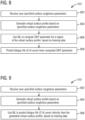
- FIG. 9 illustrates a third example implementation of a method 900 for predicting fatigue response of a material based on surface roughness.
- the proposed method 900 utilizes ML to predict fatigue life directly from the generated virtual surface profile.
- a user input is received specifying values of one or more surface roughness parameters characterizing a surface of the material for which fatigue life is to be predicted.
- the specified surface roughness parameters may include one or more of the surface roughness parameters described above, or may include additional or different surface roughness parameters.
- Block 904 of the method 900 involves generating at least one virtual surface profile based on the surface roughness parameters specified in block 902.
- the virtual surface profile may be generated using one or more of the techniques illustrated above referring to FIG. 4-6 .
- the fatigue life of the material is predicted (and may also be graphically displayed on a display screen), for example, in the form of an S-N curve, directly from the generated virtual surface profile, using the ML based model.
- the ML based model is trained on previously generated data points pertaining to a large number of sample virtual surface profiles. Each training data point is generated by simulating a stress field on a respective sample virtual surface profile using FEA, and computing therefrom an SWT parameter for a region of the sample virtual surface profile, and determining fatigue life (S-N curve) corresponding to the sample virtual surface profile from the computed SWT parameter.
- the ML based model of FIG. 9 may be thus trained to map the input surface profile to the predicted S-N curve.
- the method 700 ( FIG. 7 ) and the method 800 ( FIG. 8 ) may be utilized.
- the implementation of the method 900 is based on the understanding that the simulated stress fields contain enough information to be able to predict when a component would fail. However, this might involve a large amount of data for the ML based model to process and learn patterns from. Accordingly, the method 900 may be implemented only after a sufficiently large number of data points are generated linking the stress fields to the eventual S-N curves.
- the methods 700 and 800 may be utilized to allow the ML based model to reach to the required level of learning.
- aspects of the present disclosure may include a system, a method, and/or a computer program product at any possible technical detail level of integration
- the computer program product may include a computer readable storage medium (or media) having computer readable program instructions thereon for causing a processor to carry out aspects of the present disclosure.
- a computer readable storage medium is understood to be a non-transitory storage medium, which is not to be construed as being transitory signals per se, such as radio waves or other freely propagating electromagnetic waves, electromagnetic waves propagating through a waveguide or other transmission media (e.g., light pulses passing through a fiber-optic cable), or electrical signals transmitted through a wire.
- the computer readable storage medium can be a tangible device that can retain and store instructions for use by an instruction execution device.
- the computer readable storage medium may be, for example, but is not limited to, an electronic storage device, a magnetic storage device, an optical storage device, an electromagnetic storage device, a semiconductor storage device, or any suitable combination of the foregoing.
- a non-exhaustive list of more specific examples of the computer readable storage medium includes the following: a portable computer diskette, a hard disk, a random access memory (RAM), a read-only memory (ROM), an erasable programmable read-only memory (EPROM or Flash memory), a static random access memory (SRAM), a portable compact disc read-only memory (CD-ROM), a digital versatile disk (DVD), a memory stick, a floppy disk, a mechanically encoded device such as punch-cards or raised structures in a groove having instructions recorded thereon, and any suitable combination of the foregoing.
- RAM random access memory
- ROM read-only memory
- EPROM or Flash memory erasable programmable read-only memory
- SRAM static random access memory
- CD-ROM compact disc read-only memory
- DVD digital versatile disk
- memory stick a floppy disk
- a mechanically encoded device such as punch-cards or raised structures in a groove having instructions recorded thereon
- Computer readable program instructions described herein can be downloaded to respective computing/processing devices from a computer readable storage medium or to an external computer or external storage device via a network, for example, the Internet, a local area network, a wide area network and/or a wireless network.
- the network may comprise copper transmission cables, optical transmission fibers, wireless transmission, routers, firewalls, switches, gateway computers and/or edge servers.
- a network adapter card or network interface in each computing/processing device receives computer readable program instructions from the network and forwards the computer readable program instructions for storage in a computer readable storage medium within the respective computing/processing device.
- These computer readable program instructions may be provided to a processor of a general purpose computer, special purpose computer, or other programmable data processing apparatus to produce a machine, such that the instructions, which execute via the processor of the computer or other programmable data processing apparatus, create means for implementing the functions/acts specified in the flowchart and/or block diagram block or blocks.
- These computer readable program instructions may also be stored in a computer readable storage medium that can direct a computer, a programmable data processing apparatus, and/or other devices to function in a particular manner, such that the computer readable storage medium having instructions stored therein comprises an article of manufacture including instructions which implement aspects of the function/act specified in the flowchart and/or block diagram block or blocks.
- the computer readable program instructions may also be loaded onto a computer, other programmable data processing apparatus, or other device to cause a series of operational steps to be performed on the computer, other programmable apparatus or other device to produce a computer implemented process, such that the instructions which execute on the computer, other programmable apparatus, or other device implement the functions/acts specified in the flowchart and/or block diagram block or blocks.
- An activity performed automatically is performed in response to one or more executable instructions or device operation without user direct initiation of the activity.
Landscapes
- Engineering & Computer Science (AREA)
- Theoretical Computer Science (AREA)
- Physics & Mathematics (AREA)
- Evolutionary Computation (AREA)
- Software Systems (AREA)
- General Physics & Mathematics (AREA)
- General Engineering & Computer Science (AREA)
- Artificial Intelligence (AREA)
- Computing Systems (AREA)
- Health & Medical Sciences (AREA)
- General Health & Medical Sciences (AREA)
- Molecular Biology (AREA)
- Computational Linguistics (AREA)
- Biophysics (AREA)
- Biomedical Technology (AREA)
- Mathematical Physics (AREA)
- Life Sciences & Earth Sciences (AREA)
- Data Mining & Analysis (AREA)
- Computer Hardware Design (AREA)
- Geometry (AREA)
- Computer Vision & Pattern Recognition (AREA)
- Medical Informatics (AREA)
- Probability & Statistics with Applications (AREA)
- Management, Administration, Business Operations System, And Electronic Commerce (AREA)
- Investigating Strength Of Materials By Application Of Mechanical Stress (AREA)
Description
- The present disclosure relates, in general, to the field of material fatigue response prediction. Embodiments of the present disclosure are applicable, for example, for predicting fatigue life of additively manufactured parts from surface roughness parameters.
- Industrial use of additive manufacturing (AM) is becoming ever so common for manufacturing complex parts with high repeatability and performance. Use of AM technologies save time and resources, which are one of the advantages of AM over conventional manufacturing techniques. However, parts fabricated by AM generally have poor surface roughness. Moreover, surface roughness varies from region to region within a component based on geometry (e.g. overhang angle).
- Surface quality of a part may have a significant impact on the fatigue life of the part. Surface preparation and machining techniques that reduce surface roughness have been successfully employed to extend fatigue lives of parts that are subjected to cyclic stresses. While such methods may be applicable generally to external surfaces of additively manufactured parts, the internal "as-built" surfaces of complex geometry parts may prove more challenging to modify.
- Techniques have been developed for assessing the influence of surface roughness on fatigue performance. However, state of the art techniques require expensive and time-consuming experimentation and/or heavy computational resources.
- The publication from Belfiore et al entitled "A hybrid approach to the development of a multilayer neural network for wear and fatigue prediction in metal forming", TRIBOLOGY INTERNATIONAL, ELSEVIER LTD, AMSTERDAM, NL, vol. 40, no. 10-12, 28 August 2007 (2007-08-28), pages 1705-1717, ISSN: 0301-679X, DOI: 10.1016/J.TRIBOINT.2007.01.008 describes a method for surface damage prediction for the case of metal forming, more precisely flow forming where a workpiece coming from a primary process is plastically deformed under the action of a roller, which influences the surface fatigue of the roller.
- Patent document
US 2018/113967 A1 (AGRAWAL ANKIT [US] ET AL) 26 April 2018 (2018-04-26) pertains to the prediction of fatigue strength of steel alloys comprising deriving data like steel fatigue from material databases. - Briefly, aspects of the present disclosure are directed to techniques for prediction of fatigue response based on surface roughness that address at least some of the technical challenges mentioned above.
- According to an aspect of the present disclosure, a computer-implemented method is provided for predicting a fatigue response of a material. The method comprises receiving a user input specifying one or more surface roughness parameters that characterize a surface of a material for which fatigue life is to be predicted. The method further comprises generating at least one realistic virtual surface profile from the specified one or more surface roughness parameters. The method further comprises predicting fatigue life of the material in dependence of a stress field applied to the generated virtual surface profile.
- In accordance with specific non-limiting embodiments disclosed herein, the virtual surface profile may be generated utilizing machine learning based generative models, frequency pattern matching, Autoregressive Moving Average (ARMA) models, or combinations thereof. Furthermore, in accordance with specific non-limiting embodiments disclosed herein, the prediction of the fatigue life may be carried out utilizing finite element analysis based simulations, machine learning methods, or combinations thereof.
- Other aspects of the present disclosure implement features of the above-described method in computing systems and computer program products.
- The foregoing and other aspects of the present disclosure are best understood from the following detailed description when read in connection with the accompanying drawings. To easily identify the discussion of any element or act, the most significant digit or digits in a reference number refer to the figure number in which the element or act is first introduced.
-
FIG. 1 is a block diagram of an example of a computing system wherein aspects of the present disclosure may be implemented -
FIG. 2 is a flowchart broadly illustrating a method for predicting fatigue response based on surface roughness. -
FIG. 3 illustrates a 1D surface curve showing microscopic asperities. -
FIG. 4 is a flowchart illustrating an example method for generating a virtual surface profile by a machine learning based generative model. -
FIG. 5 is a flowchart illustrating an example method for generating a virtual surface profile by an Autoregressive Moving Average (ARMA) model. -
FIG. 6 is a flowchart illustrating an example method for generating a virtual surface profile based on frequency pattern matching. -
FIG. 7 is a flowchart illustrating a method for predicting fatigue response based on surface roughness according to a first example implementation. -
FIG. 8 is a flowchart illustrating a method for predicting fatigue response based on surface roughness according to a second example implementation. -
FIG. 9 is a flowchart illustrating a method for predicting fatigue life based on surface roughness according to a third example implementation. - Aspects of the present disclosure relate to prediction of fatigue response based on surface roughness. Surface roughness is generally poor for parts fabricated by additive manufacturing (AM), which may significantly affect the fatigue performance of such parts. To assess surface roughness, one can perform surface height measurements, which may be expensive to perform and/or not accessible to all users. To assess the fatigue life of a part, a known approach is to not only quantify the surface roughness, but also generate a huge database of fatigue data corresponding to the different surface conditions. Generating such database currently is done through experiments, meaning that a large number of test specimens need to be manufactured with different surface conditions and then tested. Such an experimental campaign may be time consuming and expensive. Moreover, one needs to repeat it for different AM machines, process settings and powders. An alternative to the experimental approach is to predict the effect of surface roughness on fatigue life through simulation techniques. However, such techniques may be computationally intensive and time consuming. Furthermore, such techniques also require surface measurements, which may be difficult and expensive to perform.
- The techniques disclosed herein address at least the above described problems by automatically generating a realistic virtual surface profile based on user-specified surface roughness parameters and predicting the corresponding fatigue property in dependence of a stress field applied to the virtual surface profile. The proposed techniques rely on finite element analyses (FEA), advanced machine learning (ML) methods, or combinations thereof. Using the proposed techniques, one can obtain in an efficient numerical way the fatigue property corresponding to any user defined surface roughness parameters, thereby avoiding expensive and time-consuming experimental methods. Aspects of present disclosure may be embodied in a computer-aided engineering (CAE) or computer-aided manufacturing (CAM) package.
- Turning now to
FIG. 1 , a computing system 100 is generally shown wherein aspects of the present disclosure may be implemented. The computing system 100 can be an electronic, computer framework comprising and/or employing any number and combination of computing devices and networks utilizing various communication technologies. The computing system 100 may be easily scalable, extensible, and modular, with the ability to change to different services or reconfigure some features independently of others. The computing system 100 may be, for example, a server, desktop computer, laptop computer, tablet computer, or smartphone. In some examples, computing system 100 may be a cloud computing node. - Computing system 100 may be described in the general context of computer executable instructions, such as program modules, being executed by a computing system. Generally, program modules may include routines, programs, objects, components, logic, data structures, and so on that perform particular tasks or implement particular abstract data types. Computing system 100 may be practiced in distributed cloud computing environments where tasks are performed by remote processing devices that are linked through a communications network. In a distributed cloud computing environment, program modules may be located in both local and remote computing system storage media including memory storage devices.
- As shown in
FIG. 1 , the computing system 100 has one ormore processors 102, which may include, for example, one or more central processing units (CPU), graphics processing units (GPU), or any other processor known in the art. Theprocessors 102 can be a single-core processor, multi-core processor, computing cluster, or any number of other configurations. Theprocessors 102, also referred to as processing circuits, are coupled via asystem bus 104 to asystem memory 106 and various other components. Thesystem memory 106 can include a read only memory orROM 108 and a random access memory orRAM 110. TheROM 108 is coupled to thesystem bus 104 and may include a basic input/output system (BIOS), which controls certain basic functions of the computing system 100. TheRAM 110 is read-write memory coupled to thesystem bus 104 for use by theprocessors 102. Thesystem memory 106 provides temporary memory space for operations of said instructions during operation. Thesystem memory 106 can include random access memory (RAM), read only memory, flash memory, or any other suitable memory systems. - The computing system 100 comprises an I/O adapter 112 (input/output adapter) and a
communications adapter 114 coupled to thesystem bus 104. The I/O adapter 112 may be a small computer system interface (SCSI) adapter that communicates with ahard disk 116 and/or any other similar component. The I/O adapter 112 and thehard disk 116 are collectively referred to herein as amass storage 118. -
Software 120 for execution on the computing system 100 may be stored in themass storage 118. Themass storage 118 is an example of a tangible storage medium readable by theprocessors 102, where thesoftware 120 is stored as instructions for execution by theprocessors 102 to cause the computing system 100 to operate, such as is described herein below with respect to the various figures. Examples of computer program product and the execution of such instruction is discussed herein in more detail. Thecommunications adapter 114 interconnects thesystem bus 104 with anetwork 122, which may be an outside network, enabling the computing system 100 to communicate with other such systems. In one embodiment, a portion of thesystem memory 106 and themass storage 118 collectively store an operating system, which may be any appropriate operating system, to coordinate the functions of the various components shown inFIG. 1 . - Additional input/output devices are shown as connected to the
system bus 104 via adisplay adapter 124 and aninterface adapter 126. In one embodiment, the I/O adapter 112, thecommunications adapter 114, thedisplay adapter 124 and theinterface adapter 126 may be connected to one or more I/O buses that are connected to thesystem bus 104 via an intermediate bus bridge (not shown). A display 128 (e.g., a screen or a display monitor) is connected to thesystem bus 104 by thedisplay adapter 124, which may include a graphics controller to improve the performance of graphics intensive applications and a video controller. Akeyboard 130, amouse 132, among other input/output devices, can be interconnected to thesystem bus 104 via theinterface adapter 126, which may include, for example, a Super I/O chip integrating multiple device adapters into a single integrated circuit. Suitable I/O buses for connecting peripheral devices such as hard disk controllers, network adapters, and graphics adapters typically include common protocols, such as the Peripheral Component Interconnect (PCI). Thus, as configured inFIG. 1 , the computing system 100 includes processing capability in the form of theprocessors 102, and, storage capability including thesystem memory 106 and themass storage 118, input means such as thekeyboard 130 and themouse 132, and output capability including thedisplay 128. - In some embodiments, the
communications adapter 114 can transmit data using any suitable interface or protocol, such as the internet small computing system interface, among others. Thenetwork 122 may be a cellular network, a radio network, a wide area network (WAN), a local area network (LAN), or the Internet, among others. An external computing device may connect to the computing system 100 through thenetwork 122. In some examples, an external computing device may be an external webserver or a cloud computing node. - It is to be understood that the block diagram of
FIG. 1 is not intended to indicate that the computing system 100 is to include all of the components shown inFIG. 1 . Rather, the computing system 100 can include any appropriate fewer or additional components not illustrated inFIG. 1 (e.g., additional memory components, embedded controllers, modules, additional network interfaces, etc.). Further, the embodiments described herein with respect to computing system 100 may be implemented with any appropriate logic, wherein the logic, as referred to herein, can include any suitable hardware (e.g., a processor, an embedded controller, or an application specific integrated circuit, among others), software (e.g., an application, among others), firmware, or any suitable combination of hardware, software, and firmware, in various embodiments. -
FIG. 2 illustrates amethod 200 for predicting a fatigue response of a material according to an aspect of the present disclosure. Themethod 200 may be implemented, for example, in conjunction with the computing system 100 illustrated inFIG. 1 .Block 202 of themethod 200 involves receiving a user input specifying values of one or more surface roughness parameters. Herein, the user may provide input on one or more roughness parameters that are typically used to characterize the surface of the material for which fatigue life is to be predicted. The one or more parameters may be selected, for example, from the non-limiting examples of surface roughness parameters provided below. It is to be appreciated that the disclosed techniques may be used to account for additional or different parameters. -
FIG. 3 shows an illustrative one-dimensional (1D)surface curve 300 defining a surface having microscopic asperities, where theaxis 302 represents a distance across the surface (x) and the axis y represents asperity height (y). Assuming the profile is represented as a set of (xi, yi) points, the surface roughness parameters can be defined as: - Arithmetical mean deviation:

- Root mean squared:

- Maximum valley depth:

- Maximum peak height:
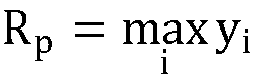
- Maximum height of the profile: Rt = Rp - Rv
- Average maximum valley depth:

- Average maximum peak height:

- Skewness:

- Kurtosis:

- Referring back to
FIG. 2 , block 204 of themethod 200 involves generating at least one realistic virtual surface profile from the specified one or more surface roughness parameters. In the context of the present specification, a "virtual surface profile" refers to a machine generated surface profile obtained from user-specified surface roughness parameter values using a data-driven generative method. In this regard, a virtual surface profile is an artificial surface profile, and is not to be construed as being generated from surface measurements of a real surface. However, a virtual surface may be generated to closely resemble real surface profiles in an available data set. Accordingly, such a virtual surface profile is also described as being "realistic", while not being real. Example embodiments data-driven approaches for generating virtual surface profiles are illustrated below referring toFIG. 4-6 . Continuing with reference toFIG. 2 , block 206 of themethod 200 involves predicting fatigue life of the material based on a stress field applied to the generated virtual surface profile. This may comprise generating a stress-life (S-N curve) plotting cyclic stress amplitude S against fatigue life Nf defined by number of cycles to failure. The generated S-N curve may be graphically displayed on a display screen. Exemplary non-limiting implementations within the scope of the above-describedmethod 200 are illustrated below referring toFIG. 7-9 . -
FIG. 4 illustrates afirst example method 400 for generating one or more virtual surface profiles based on the user-specified surface roughness parameters. Themethod 400 utilizes a machine learning based generative model. Examples of such models include Generative Adversarial Networks (GAN), Variational Auto-Encoders, or their variations (e.g. WGAN-GP), among others. The generative model may be trained on the available data and utilized to generate novel virtual surface profiles that resemble the surface profiles in the available data. In the shown example, themethod 400 utilizes a GAN. -
Block 402 of themethod 400 involves obtaining, as training data, 1D surface profiles s from surface measurements and calculated roughness parameters r of a plurality of real surfaces. The data from real surfaces may be pre-processed, which may, for example, involve the steps of resampling the data to obtain same sampling rate throughout all the samples, splitting the data to obtain the same sample length, detrending, etc.Block 404 of themethod 400 involves training the generative model using the training data obtained atblock 402. Atblock 406, the generative model is modified to request to the generator to match one or more of the surface roughness parameters specified by the user. In the case of GAN, this can be achieved, for example, by modifying the objective function that the process optimizes by adding the following term:

- In the above term, s̃ = G(z, r) are the generated 1D surface profiles, as function of the generator G, z is latent vector and Ri(*) is the function that represents the roughness parameters i. The objective function E is summed over the number of surface roughness parameters specified, which in this case is 9.
-
Block 408 of themethod 400 involves the generation of a specified number of new (virtual) 1D surface profiles s̃, that closely resemble the surface profiles s in the training data, based on the modified objective function of the generative model. As an additional step, atblock 410, the generated virtual 1D surface profile may be smoothed to reduce sharp peaks, for example, using spectral or spline interpolation. -
FIG. 5 illustrates asecond example method 500 for generating one or more virtual surface profiles based on the user-specified surface roughness parameters. Themethod 500 uses an Autoregressive Moving Average (ARMA) model to generate new surface profiles. The basic principle of this approach is to identify a suitable mathematical model describing the surface height profile from the available data and using the same model to generate new surface profiles. -
Block 502 of themethod 500 involves obtaining surface profiles from available data. The available data comprises surface profiles obtained from surface measurements and calculated roughness parameters of a plurality of real surfaces. The data from real surfaces may be pre-processed, which may, for example, involve the steps of resampling the data to obtain same sampling rate throughout all the samples, splitting the data to obtain the same sample length, detrending, etc.Block 504 of themethod 500 involves choosing datasets having surface roughness parameters R that are already close to the user-specified surface roughness parameters R*. -
Block 506 of the method of themethod 500 involves determining a mathematical model of the following form from the chosen dataset.

- In the above model, yt denotes the surface height at spatial position xt and the coefficients ai and bj determine the autoregressive (AR) and moving average (MA) part of the model, respectively. Furthermore, the quantity εt denotes white noise, i.e. a random input with mean zero and fixed variance σ 2, at position xt.
- The following model parameters are determined from the chosen dataset, namely order of the AR and MA contribution p, q, coefficients of the AR and MA contribution a 1, ..., ap, b 1, ..., bq and variation of the input noise σ 2. For each dataset, these quantities may be identified using, for example, a Box-Jenkins approach in combination with a minimization of Akaike's Information Criterion (AIC). The Box-Jenkins approach is discussed in the publication: Box, George, & Jenkins, Gwilym (1970). Time Series Analysis: Forecasting and Control. San Francisco: Holden-Day. The Akaike's Information Criterion (AIC) is discussed in the publication: Hyndman, R.J., & Athanasopoulos, G. (2018) Forecasting: principles and practice, 2nd edition, OTexts: Melbourne, Australia. OTexts.com/fpp2. Accessed on August 29, 2019.
- Under the assumption that there is a single model describing all surface profiles, the aforementioned model parameters may be obtained by averaging the corresponding results from all datasets. The result is an ARMA model describing the spatial evolution of the surface height profile.
-
Block 508 of themethod 500 involves obtaining one or more new surface profiles z using the ARMA model developed inblock 506. The new surface profile z may be obtained by specifying an initial height at x 0 = 0 (for simplicity this can be assumed to be zero) and creating a series of random white noise input εt with variance σ 2. As would be expected, the new surface profile z would have surface roughness parameter parameters Rz, where Rz≈R*. Finally, atblock 510 of themethod 500, a virtual surface z* is generated which would have the user-specified surface roughness parameter R*. The surface profile z* is determined as z* = (R*/Rz) · z. -
FIG. 6 illustrates athird example method 600 for generating one or more virtual surface profiles based on the user-specified surface roughness parameters. While themethod 500 shown inFIG. 5 works directly on the height data of the surface profiles, themethod 600 shown inFIG. 6 identifies typical surface height frequency patterns from available data and creating new (virtual) surface profiles based on those patterns. -
Block 602 of theexample method 600 involves obtaining surface profiles from available data. The available data comprises surface profiles obtained from surface measurements and calculated roughness parameters of a plurality of real surfaces. The data from real surfaces may be pre-processed, which may, for example, involve the steps of resampling the data to obtain same sampling rate throughout all the samples, splitting the data to obtain the same sample length, detrending, etc.Block 604 of themethod 600 involves choosing a surface profile g from the available data. A particular strategy for the choice is presented atblock 612.Block 606 of themethod 600 involves computing a Power Spectrum (PS) of g, namely, PS(g), and an underlying model ĝ for it via the nonlinear least squares (NLS) method. It has been observed that the following parameterized model presents a good candidate.
- In the above model, the parameters a, b, c, β may be identified by NLS.
-
Block 608 of themethod 600 involves identifying a surrogate model for the residual or noise term r̂ = PS(g) - ĝ, again via NLS. Typically, r̂ is normally distributed with variance decaying exponentially for increasing frequencies. This is due to the fact that such frequencies larger than a certain threshold value are essentially non-existent. This decay motivates a model of the form

- In the above model σr̂ (f) = γ · exp (-δ · f). It can be seen that the variance decreases if the frequency f increases.
-
Block 610 of themethod 600 involves creating a random Power Spectrum ĥ following the trend ĝ(f) and a noise term r̂(f) from above-mentioned distribution. The generated surface profile will eventually have a PS close to ĥ. -
Block 612 of themethod 600 involves scaling the profile g by a factor ω such that g' = ω · g attains a desired surface roughness value as specified by the user. In order to minimize the distortion in the data, inblock 604, the surface g should be chosen as the one having a roughness value that is closest to the desired surface roughness among all datasets. -
Block 614 of themethod 600 involves generating one or more new (virtual) surface profiles such that the new surface profile has (a) the same height distribution and hence the same surface roughness as g', and (b) a Power Spectrum that is very close to ĥ and is therefore assumed to be realistic as ĥ was identified from the data. The new surface profile(s) may be generated using an iterative version of the amplitude adjusted Fourier transform (AAFT). A discussion on AAFT is available in the publication: Schreiber, Thomas, & Andreas Schmitz. "Improved surrogate data for nonlinearity tests." Physical Review Letters 77.4 (1996): 635. - One or more of the methods illustrated in
FIG. 4-6 may be used, individually, or in combination, to generate new (virtual) surface profiles. For example, the methods ofFIG. 4 and6 may be combined to achieve machine learning generated models that resemble the training data and also achieve the frequency patterns extracted from the available data. A first way to accomplish the above is to proceed with themethod 400 shown inFIG. 4 , and then (after block 410) add additional blocks as described for themethod 600 ofFIG. 6 . A second way to accomplish the above is to add a term in the objective function of the generative model (seeblock 406 ofFIG. 4 ) to penalize in the generative process surface profiles whose frequency content differ from the desired one. - Referring now to
FIG. 7 , a first example implementation is described of amethod 700 for predicting fatigue response of a material based on surface roughness. Atblock 702 of themethod 700, a user input is received specifying values of one or more surface roughness parameters characterizing a surface of the material for which fatigue life is to be predicted. The specified surface roughness parameters may include one or more of the surface roughness parameters described above, or may include additional or different surface roughness parameters.Block 704 of themethod 700 involves generating at least one virtual surface profile based on the surface roughness parameters specified inblock 702. The virtual surface profile may be generated using one or more of the techniques illustrated above referring toFIG. 4-6 . - At
block 706, themethod 700 involves creating a simulation model using finite element analysis (FEA), based on the generated virtual surface profile. The method includes applying appropriate loads and constraints to the FEA model to simulate a stress field on the virtual surface. In some embodiments, the simulated stress field may be graphically displayed on a display screen. While at a global level, the material may be assumed to exhibit a linear elastic behavior, at a local level, the material may exhibit plastic behavior due to stress concentration effects caused by surface roughness, porosity, etc. Accordingly, atblock 708, themethod 700 computes a Smith-Watson-Topper (SWT) parameter to account for the localized plastic behavior, in order to predict fatigue life of the material. The SWT parameter, is known in the art (see Smith, K. N., Watson, P. and Topper, T. H. (1970) A stress-strain function for the fatigue of materials. J. Mater. 5, 767-778.), and is defined by the following equation:
- In the above equation, the term on the left is the SWT parameter, which is a product of the maximum stress σmax and the strain value Δε/2 for that said maximum stress. In the expression on the right, Nf denotes fatigue life defined by number of cycles to failure, b is the Basquin exponent, c is the Coffin-Mansion exponent, and σ'f , E and ε'f are constants. The values σmax and Δε/2 may be computed from the FEA model, to thereby determine a value of the SWT parameter for a region of the virtual surface profile, which may be then used to determine fatigue life Nf based on the above equation.
- Finally, at
block 710 of themethod 700, a fatigue life of the material is predicted based on the computed SWT parameter. This may comprise generating an S-N curve plotting cyclic stress amplitude S against fatigue life Nf defined by number of cycles to failure. The generated S-N curve may be graphically displayed on a display screen. The computed SWT parameters may be related to the S-N curve through the well-known Basquin-Coffin-Mansion equation. -
FIG. 8 illustrates a second example implementation of amethod 800 for predicting fatigue response of a material based on surface roughness. The proposedmethod 800 uses a combination of machine learning (ML) and FEA based simulation to speed up the computation of the SWT parameter in order to predict fatigue life. - At
block 802 of themethod 800, a user input is received specifying values of one or more surface roughness parameters characterizing a surface of the material for which fatigue life is to be predicted. The specified surface roughness parameters may include one or more of the surface roughness parameters described above, or may include additional or different surface roughness parameters.Block 804 of themethod 800 involves generating at least one virtual surface profile based on the surface roughness parameters specified inblock 802. The virtual surface profile may be generated using one or more of the techniques illustrated above referring toFIG. 4-6 . - At
block 806 of themethod 800, a value of the SWT parameter for a region of the virtual surface profile is determined using an ML based model. The ML based model is trained on previously generated data points pertaining to a large number of sample virtual surface profiles. Each training data point is generated by simulating a stress field on a respective sample virtual surface profile using FEA, and computing therefrom an SWT parameter for a region of the sample virtual surface profile, similar to that described in connection withblocks FIG. 7 . The ML based model ofFIG. 8 may be thus trained to map the input surface profile to the result of the finite element simulation (i.e., the computed value of the SWT parameter). To this end, themethod 700 ofFIG. 7 may be utilized for generating the training data points for implementing themethod 800 ofFIG. 8 . Once a sufficiently large number of data points are generated using themethod 700, themethod 800 may be implemented, to accelerate the computation of the SWT parameter. - At
block 808 of themethod 800, a fatigue life of the material is predicted based on the computed SWT parameter. This may comprise generating an S-N curve plotting cyclic stress amplitude S against fatigue life Nf defined by number of cycles to failure. The generated S-N curve may be graphically displayed on a display screen. The computed SWT parameters may be related to the S-N curve through the well-known Basquin-Coffin-Mansion equation. In case of themethod 800, the determination of the predicted fatigue life is greatly simplified by computing the SWT parameter directly based on ML, bypassing the more time-consuming FEA based approach. -
FIG. 9 illustrates a third example implementation of amethod 900 for predicting fatigue response of a material based on surface roughness. The proposedmethod 900 utilizes ML to predict fatigue life directly from the generated virtual surface profile. - At
block 902 of themethod 900, a user input is received specifying values of one or more surface roughness parameters characterizing a surface of the material for which fatigue life is to be predicted. The specified surface roughness parameters may include one or more of the surface roughness parameters described above, or may include additional or different surface roughness parameters.Block 904 of themethod 900 involves generating at least one virtual surface profile based on the surface roughness parameters specified inblock 902. The virtual surface profile may be generated using one or more of the techniques illustrated above referring toFIG. 4-6 . - At
block 906 of themethod 900, the fatigue life of the material is predicted (and may also be graphically displayed on a display screen), for example, in the form of an S-N curve, directly from the generated virtual surface profile, using the ML based model. The ML based model is trained on previously generated data points pertaining to a large number of sample virtual surface profiles. Each training data point is generated by simulating a stress field on a respective sample virtual surface profile using FEA, and computing therefrom an SWT parameter for a region of the sample virtual surface profile, and determining fatigue life (S-N curve) corresponding to the sample virtual surface profile from the computed SWT parameter. The ML based model ofFIG. 9 may be thus trained to map the input surface profile to the predicted S-N curve. - To generate the training data points for implementing the
method 900, the method 700 (FIG. 7 ) and the method 800 (FIG. 8 ) may be utilized. The implementation of themethod 900 is based on the understanding that the simulated stress fields contain enough information to be able to predict when a component would fail. However, this might involve a large amount of data for the ML based model to process and learn patterns from. Accordingly, themethod 900 may be implemented only after a sufficiently large number of data points are generated linking the stress fields to the eventual S-N curves. Themethods - Aspects of the present disclosure may include a system, a method, and/or a computer program product at any possible technical detail level of integration. The computer program product may include a computer readable storage medium (or media) having computer readable program instructions thereon for causing a processor to carry out aspects of the present disclosure. A computer readable storage medium, as used herein, is understood to be a non-transitory storage medium, which is not to be construed as being transitory signals per se, such as radio waves or other freely propagating electromagnetic waves, electromagnetic waves propagating through a waveguide or other transmission media (e.g., light pulses passing through a fiber-optic cable), or electrical signals transmitted through a wire.
- The computer readable storage medium can be a tangible device that can retain and store instructions for use by an instruction execution device. The computer readable storage medium may be, for example, but is not limited to, an electronic storage device, a magnetic storage device, an optical storage device, an electromagnetic storage device, a semiconductor storage device, or any suitable combination of the foregoing. A non-exhaustive list of more specific examples of the computer readable storage medium includes the following: a portable computer diskette, a hard disk, a random access memory (RAM), a read-only memory (ROM), an erasable programmable read-only memory (EPROM or Flash memory), a static random access memory (SRAM), a portable compact disc read-only memory (CD-ROM), a digital versatile disk (DVD), a memory stick, a floppy disk, a mechanically encoded device such as punch-cards or raised structures in a groove having instructions recorded thereon, and any suitable combination of the foregoing.
- Computer readable program instructions described herein can be downloaded to respective computing/processing devices from a computer readable storage medium or to an external computer or external storage device via a network, for example, the Internet, a local area network, a wide area network and/or a wireless network. The network may comprise copper transmission cables, optical transmission fibers, wireless transmission, routers, firewalls, switches, gateway computers and/or edge servers. A network adapter card or network interface in each computing/processing device receives computer readable program instructions from the network and forwards the computer readable program instructions for storage in a computer readable storage medium within the respective computing/processing device.
- Aspects of the present disclosure are described herein with reference to flowchart illustrations and/or block diagrams of methods, apparatus (systems), and computer program products according to embodiments of the disclosure. It will be understood that each block of the flowchart illustrations and/or block diagrams, and combinations of blocks in the flowchart illustrations and/or block diagrams, can be implemented by computer readable program instructions.
- These computer readable program instructions may be provided to a processor of a general purpose computer, special purpose computer, or other programmable data processing apparatus to produce a machine, such that the instructions, which execute via the processor of the computer or other programmable data processing apparatus, create means for implementing the functions/acts specified in the flowchart and/or block diagram block or blocks. These computer readable program instructions may also be stored in a computer readable storage medium that can direct a computer, a programmable data processing apparatus, and/or other devices to function in a particular manner, such that the computer readable storage medium having instructions stored therein comprises an article of manufacture including instructions which implement aspects of the function/act specified in the flowchart and/or block diagram block or blocks.
- The computer readable program instructions may also be loaded onto a computer, other programmable data processing apparatus, or other device to cause a series of operational steps to be performed on the computer, other programmable apparatus or other device to produce a computer implemented process, such that the instructions which execute on the computer, other programmable apparatus, or other device implement the functions/acts specified in the flowchart and/or block diagram block or blocks.
- The functions and process steps herein may be performed automatically, wholly or partially in response to user command. An activity (including a step) performed automatically is performed in response to one or more executable instructions or device operation without user direct initiation of the activity.
- The system and processes of the figures are not exclusive. Other systems and processes may be derived in accordance with the principles of the disclosure to accomplish the same objectives. Although this disclosure has been described with reference to particular embodiments, it is to be understood that the embodiments and variations shown and described herein are for illustration purposes only. Modifications to the current design may be implemented by those skilled in the art, without departing from the scope of the disclosure. The invention is defined by the appended independent claims. The dependent claims define preferred embodiments.
Claims (14)
- A computer-implemented method (200) for predicting a fatigue response of a material, comprising:Receiving a user input specifying one or more surface roughness parameters that characterize a surface of a material for which fatigue life is to be predicted (202),generating at least one realistic artificial virtual surface profile from the specified one or more surface roughness parameters using a data-driven generative method to closely resemble real surface profiles (204) by a machine learning based generative model (400), the machine learning based generative model being developed using training data (404) comprising surface profiles obtained from surface measurements and calculated roughness parameters of a plurality of real surfaces (402), andpredicting fatigue life of the material in dependence of a stress field applied to the generated virtual surface profile (206).
- The method according to claim 1, wherein the at least one virtual surface profile is generated by an Autoregressive Moving Average, "ARMA", model (500), the ARMA model being developed to describe a surface height profile (510) from available data comprising surface profiles obtained from surface measurements and calculated roughness parameters of a plurality of real surfaces (502).
- The method according to any of claims 1 and 2, wherein the at least one virtual surface profile is generated based on surface height frequency patterns (600) identified from available data comprising surface profiles obtained from surface measurements and calculated roughness parameters of a plurality of real surfaces (602).
- The method according to any of claims 1 to 3, wherein the prediction of the fatigue life of the material is based on a computation of a Smith-Watson-Topper, "SWT", parameter from the applied stress field on the virtual surface profile (700).
- The method according to claim 4, wherein the computation of the SWT parameter (700) comprises performing a finite element analysis to generate a simulated stress field on the virtual surface profile (706), and determining a value of the SWT parameter for a region of the virtual surface profile (708).
- The method according to claim 4, wherein the computation of the SWT parameter comprises determining a value of the SWT parameter for a region of the virtual surface profile using a machine learning based model (800),
Wherein the machine learning based model is trained on data points pertaining to a plurality of sample virtual surface profiles, each training data point being generated by performing finite element analysis to simulate a stress field on a respective sample virtual surface profile, and compute therefrom an SWT parameter for a region of the sample virtual surface profile (806). - The method according to any of claims 4 to 6, wherein predicting the fatigue life of the material comprises generating a stress-life (S-N) curve from the computed SWT parameter (710, 808).
- The method according to any of claims 1 to 3, wherein the fatigue life of the material is predicted based on a machine learning based model trained to predict fatigue life directly from the generated virtual surface profile (900),
wherein the machine learning based model is trained on data points pertaining to a plurality of sample virtual surface profiles, each training data point being generated by:performing finite element analysis to simulate a stress field on a respective sample virtual surface profile, and compute therefrom a Smith-Watson-Topper (SWT) parameter for a region of the sample virtual surface profile, anddetermining fatigue life corresponding to the sample virtual surface profile from the computed SWT parameter. - The method according to claim 8, predicting the fatigue life of the material comprises generating a stress-life (S-N) curve using the machine learning based model (906).
- A non-transitory computer-readable storage medium (118) including instructions that, when processed by a computer, configure the computer to perform the method (200) according to any of claims 1 to 9.
- A computing system (100) comprising:a processor (102); anda memory storing (106) instructions that, when executed by the processor (102), configure the computing system (100) to:receive a user input specifying one or more surface roughness parameters that characterize a surface of a material for which fatigue life is to be predicted (202),generate at least one realistic artificial virtual surface profile from the specified one or more surface roughness parameters using a data-driven generative method to closely resemble real surface profiles (204) by a machine learning based generative model (400), the machine learning based generative model being developed using training data (404) comprising surface profiles obtained from surface measurements and calculated roughness parameters of a plurality of real surfaces (402), andpredict fatigue life of the material in dependence of a stress field applied to the generated virtual surface profile (206).
- The computing system according to claim 11, wherein the at least one realistic virtual surface profile is generated by a machine learning based generative model, the machine learning based generative model being developed using training data comprising surface profiles obtained from surface measurements and calculated roughness parameters of a plurality of real surfaces (400).
- The computing system according to any of claims 11 and 12, wherein the at least one virtual surface profile is generated by an Autoregressive Moving Average, "ARMA", model, the ARMA model being developed to describe a surface height profile from available data comprising surface profiles obtained from surface measurements and calculated roughness parameters of a plurality of real surfaces (500).
- The computing system according to any of claims 11 to 13, wherein the at least one virtual surface profile is generated based on surface height frequency patterns identified from available data comprising surface profiles obtained from surface measurements and calculated roughness parameters of a plurality of real surfaces (600).
Applications Claiming Priority (1)
| Application Number | Priority Date | Filing Date | Title |
|---|---|---|---|
| PCT/US2020/019691 WO2021173121A1 (en) | 2020-02-25 | 2020-02-25 | System and method for fatigue response prediction |
Publications (3)
| Publication Number | Publication Date |
|---|---|
| EP4094177A1 EP4094177A1 (en) | 2022-11-30 |
| EP4094177B1 true EP4094177B1 (en) | 2025-04-02 |
| EP4094177C0 EP4094177C0 (en) | 2025-04-02 |
Family
ID=69941498
Family Applications (1)
| Application Number | Title | Priority Date | Filing Date |
|---|---|---|---|
| EP20713469.3A Active EP4094177B1 (en) | 2020-02-25 | 2020-02-25 | System and method for fatigue response prediction |
Country Status (4)
| Country | Link |
|---|---|
| US (1) | US20230062268A1 (en) |
| EP (1) | EP4094177B1 (en) |
| CN (1) | CN115176250A (en) |
| WO (1) | WO2021173121A1 (en) |
Families Citing this family (3)
| Publication number | Priority date | Publication date | Assignee | Title |
|---|---|---|---|---|
| CN114714146B (en) * | 2022-04-08 | 2023-04-07 | 北京理工大学 | Method for simultaneously predicting surface roughness and cutter abrasion |
| CN118780136B (en) * | 2024-09-09 | 2024-12-31 | 山东豪迈机械科技股份有限公司 | Tire segmented mold parameter determination method, device, equipment and readable storage medium |
| CN121525522B (en) * | 2026-01-14 | 2026-04-03 | 太行国家实验室 | Wheel disc overrun rupture rotating speed prediction method based on proxy model |
Family Cites Families (5)
| Publication number | Priority date | Publication date | Assignee | Title |
|---|---|---|---|---|
| US4860589A (en) * | 1987-12-10 | 1989-08-29 | Battelle Memorial Institute | Procedure for estimating fracture energy from fracture surface roughness |
| FR2898410B1 (en) * | 2006-03-07 | 2008-05-09 | Airbus France Sas | A METHOD OF CHARACTERIZING FATIGUE HOLDING OF A WORKPIECE FROM ITS SURFACE PROFILE |
| US10830747B2 (en) * | 2016-10-26 | 2020-11-10 | Northwestern University | System and method for predicting fatigue strength of alloys |
| CN109933952B (en) * | 2019-04-04 | 2022-09-30 | 西北工业大学 | Method for predicting fatigue life of nickel-based single crystal alloy by considering surface roughness |
| CN110763728A (en) * | 2019-11-06 | 2020-02-07 | 安徽建筑大学 | Fatigue damage assessment method based on metal surface infrared polarization thermal image characteristics |
-
2020
- 2020-02-25 EP EP20713469.3A patent/EP4094177B1/en active Active
- 2020-02-25 CN CN202080097543.3A patent/CN115176250A/en active Pending
- 2020-02-25 US US17/760,367 patent/US20230062268A1/en active Pending
- 2020-02-25 WO PCT/US2020/019691 patent/WO2021173121A1/en not_active Ceased
Also Published As
| Publication number | Publication date |
|---|---|
| US20230062268A1 (en) | 2023-03-02 |
| EP4094177A1 (en) | 2022-11-30 |
| WO2021173121A1 (en) | 2021-09-02 |
| CN115176250A (en) | 2022-10-11 |
| EP4094177C0 (en) | 2025-04-02 |
Similar Documents
| Publication | Publication Date | Title |
|---|---|---|
| CN113568821B (en) | A method, device, equipment, and medium for testing computing performance of AI chips | |
| Wang et al. | The effect of resolution on the deterministic finite element elastic-plastic rough surface contact under combined normal and tangential loading | |
| Azam et al. | A simple deterministic plastoelastohydrodynamic lubrication (PEHL) model in mixed lubrication | |
| CN111783209A (en) | An Adaptive Structural Reliability Analysis Method Combined with Learning Function and Kriging Model | |
| CN106777732B (en) | A Fatigue Reliability Analysis Method Considering Random Loads and Strength Degradation | |
| US20230062268A1 (en) | System and method for fatigue response prediction | |
| CN106096073A (en) | A kind of metal fatigue crackle life-cycle predictor method analyzing model based on the non-probability interval of damage mechanics | |
| CN118886599A (en) | Ancient building risk assessment method and device | |
| Zheng et al. | Plasto‐elastohydrodynamic lubrication performance of greased ellipsoid contact | |
| Chen et al. | Structural dynamic model updating based on multi-level weight coefficients | |
| Spinu et al. | Modelling of rough contact between linear viscoelastic materials | |
| CN118395820B (en) | Method, device, computing equipment and storage medium for correcting influence of static elastic deformation under different sideslip angles | |
| CN117973236B (en) | Correction method, system, equipment and storage medium for simulation result | |
| US20230142773A1 (en) | Method and system for real-time simulations using convergence stopping criterion | |
| CN116541978A (en) | Blade roll forming simulation method and device based on trans-scale crystal plastic model | |
| CN116187034B (en) | Uncertainty quantification-based compressor simulation credibility assessment method | |
| Alwan et al. | Improved statistical models for limited datasets in uncertainty quantification using stochastic collocation | |
| CN119294231B (en) | Intelligent second calculation method and device for rock burst, electronic equipment and storage medium | |
| CN117077487B (en) | Method and device for identifying structural overall damping based on time domain response variance parameters | |
| EP4651010A1 (en) | High resolution simulation prediction for computational fluid dynamics | |
| CN119783588B (en) | Vehicle wind tunnel simulation model building method, device, equipment and storage medium | |
| CN120124527B (en) | A model-based method and system for determining the fixed buoyancy volume of irregular underwater objects | |
| CN120235005A (en) | Multiaxial fatigue determination method, device and medium based on Crossland criterion | |
| Tian et al. | Multi-process precision surface topography characterization and simulation based on multi-Gaussian and multi-fractal model | |
| Holzinger | Leading edge erosion: A review and application of modeling strategies for the investigation of erosion-induced effects on wind turbine rotor blades |
Legal Events
| Date | Code | Title | Description |
|---|---|---|---|
| STAA | Information on the status of an ep patent application or granted ep patent |
Free format text: STATUS: UNKNOWN |
|
| STAA | Information on the status of an ep patent application or granted ep patent |
Free format text: STATUS: THE INTERNATIONAL PUBLICATION HAS BEEN MADE |
|
| PUAI | Public reference made under article 153(3) epc to a published international application that has entered the european phase |
Free format text: ORIGINAL CODE: 0009012 |
|
| STAA | Information on the status of an ep patent application or granted ep patent |
Free format text: STATUS: REQUEST FOR EXAMINATION WAS MADE |
|
| 17P | Request for examination filed |
Effective date: 20220823 |
|
| AK | Designated contracting states |
Kind code of ref document: A1 Designated state(s): AL AT BE BG CH CY CZ DE DK EE ES FI FR GB GR HR HU IE IS IT LI LT LU LV MC MK MT NL NO PL PT RO RS SE SI SK SM TR |
|
| DAV | Request for validation of the european patent (deleted) | ||
| DAX | Request for extension of the european patent (deleted) | ||
| GRAP | Despatch of communication of intention to grant a patent |
Free format text: ORIGINAL CODE: EPIDOSNIGR1 |
|
| STAA | Information on the status of an ep patent application or granted ep patent |
Free format text: STATUS: GRANT OF PATENT IS INTENDED |
|
| INTG | Intention to grant announced |
Effective date: 20240924 |
|
| GRAS | Grant fee paid |
Free format text: ORIGINAL CODE: EPIDOSNIGR3 |
|
| GRAA | (expected) grant |
Free format text: ORIGINAL CODE: 0009210 |
|
| STAA | Information on the status of an ep patent application or granted ep patent |
Free format text: STATUS: THE PATENT HAS BEEN GRANTED |
|
| AK | Designated contracting states |
Kind code of ref document: B1 Designated state(s): AL AT BE BG CH CY CZ DE DK EE ES FI FR GB GR HR HU IE IS IT LI LT LU LV MC MK MT NL NO PL PT RO RS SE SI SK SM TR |
|
| REG | Reference to a national code |
Ref country code: GB Ref legal event code: FG4D |
|
| REG | Reference to a national code |
Ref country code: CH Ref legal event code: EP |
|
| REG | Reference to a national code |
Ref country code: IE Ref legal event code: FG4D |
|
| U01 | Request for unitary effect filed |
Effective date: 20250402 |
|
| U07 | Unitary effect registered |
Designated state(s): AT BE BG DE DK EE FI FR IT LT LU LV MT NL PT RO SE SI Effective date: 20250408 |
|
| PG25 | Lapsed in a contracting state [announced via postgrant information from national office to epo] |
Ref country code: ES Free format text: LAPSE BECAUSE OF FAILURE TO SUBMIT A TRANSLATION OF THE DESCRIPTION OR TO PAY THE FEE WITHIN THE PRESCRIBED TIME-LIMIT Effective date: 20250402 |
|
| PG25 | Lapsed in a contracting state [announced via postgrant information from national office to epo] |
Ref country code: NO Free format text: LAPSE BECAUSE OF FAILURE TO SUBMIT A TRANSLATION OF THE DESCRIPTION OR TO PAY THE FEE WITHIN THE PRESCRIBED TIME-LIMIT Effective date: 20250702 Ref country code: GR Free format text: LAPSE BECAUSE OF FAILURE TO SUBMIT A TRANSLATION OF THE DESCRIPTION OR TO PAY THE FEE WITHIN THE PRESCRIBED TIME-LIMIT Effective date: 20250703 |
|
| PG25 | Lapsed in a contracting state [announced via postgrant information from national office to epo] |
Ref country code: PL Free format text: LAPSE BECAUSE OF FAILURE TO SUBMIT A TRANSLATION OF THE DESCRIPTION OR TO PAY THE FEE WITHIN THE PRESCRIBED TIME-LIMIT Effective date: 20250402 |
|
| PG25 | Lapsed in a contracting state [announced via postgrant information from national office to epo] |
Ref country code: HR Free format text: LAPSE BECAUSE OF FAILURE TO SUBMIT A TRANSLATION OF THE DESCRIPTION OR TO PAY THE FEE WITHIN THE PRESCRIBED TIME-LIMIT Effective date: 20250402 |
|
| PG25 | Lapsed in a contracting state [announced via postgrant information from national office to epo] |
Ref country code: RS Free format text: LAPSE BECAUSE OF FAILURE TO SUBMIT A TRANSLATION OF THE DESCRIPTION OR TO PAY THE FEE WITHIN THE PRESCRIBED TIME-LIMIT Effective date: 20250702 |
|
| PG25 | Lapsed in a contracting state [announced via postgrant information from national office to epo] |
Ref country code: IS Free format text: LAPSE BECAUSE OF FAILURE TO SUBMIT A TRANSLATION OF THE DESCRIPTION OR TO PAY THE FEE WITHIN THE PRESCRIBED TIME-LIMIT Effective date: 20250802 |
|
| PG25 | Lapsed in a contracting state [announced via postgrant information from national office to epo] |
Ref country code: SM Free format text: LAPSE BECAUSE OF FAILURE TO SUBMIT A TRANSLATION OF THE DESCRIPTION OR TO PAY THE FEE WITHIN THE PRESCRIBED TIME-LIMIT Effective date: 20250402 |
|
| PG25 | Lapsed in a contracting state [announced via postgrant information from national office to epo] |
Ref country code: CZ Free format text: LAPSE BECAUSE OF FAILURE TO SUBMIT A TRANSLATION OF THE DESCRIPTION OR TO PAY THE FEE WITHIN THE PRESCRIBED TIME-LIMIT Effective date: 20250402 |
|
| PG25 | Lapsed in a contracting state [announced via postgrant information from national office to epo] |
Ref country code: SK Free format text: LAPSE BECAUSE OF FAILURE TO SUBMIT A TRANSLATION OF THE DESCRIPTION OR TO PAY THE FEE WITHIN THE PRESCRIBED TIME-LIMIT Effective date: 20250402 |
|
| PLBE | No opposition filed within time limit |
Free format text: ORIGINAL CODE: 0009261 |
|
| STAA | Information on the status of an ep patent application or granted ep patent |
Free format text: STATUS: NO OPPOSITION FILED WITHIN TIME LIMIT |
|
| REG | Reference to a national code |
Ref country code: CH Ref legal event code: L10 Free format text: ST27 STATUS EVENT CODE: U-0-0-L10-L00 (AS PROVIDED BY THE NATIONAL OFFICE) Effective date: 20260211 |
|
| 26N | No opposition filed |
Effective date: 20260105 |
|
| U20 | Renewal fee for the european patent with unitary effect paid |
Year of fee payment: 7 Effective date: 20260219 |
|
| PGFP | Annual fee paid to national office [announced via postgrant information from national office to epo] |
Ref country code: GB Payment date: 20260310 Year of fee payment: 7 |