EP4094067B1 - System and method for detecting breaches in containers - Google Patents
System and method for detecting breaches in containers Download PDFInfo
- Publication number
- EP4094067B1 EP4094067B1 EP21702071.8A EP21702071A EP4094067B1 EP 4094067 B1 EP4094067 B1 EP 4094067B1 EP 21702071 A EP21702071 A EP 21702071A EP 4094067 B1 EP4094067 B1 EP 4094067B1
- Authority
- EP
- European Patent Office
- Prior art keywords
- optical sensor
- permeable
- conveyor
- pressing member
- sealed food
- Prior art date
- Legal status (The legal status is an assumption and is not a legal conclusion. Google has not performed a legal analysis and makes no representation as to the accuracy of the status listed.)
- Active
Links
Images
Classifications
-
- G—PHYSICS
- G01—MEASURING; TESTING
- G01M—TESTING STATIC OR DYNAMIC BALANCE OF MACHINES OR STRUCTURES; TESTING OF STRUCTURES OR APPARATUS, NOT OTHERWISE PROVIDED FOR
- G01M3/00—Investigating fluid-tightness of structures
- G01M3/38—Investigating fluid-tightness of structures by using light
-
- G—PHYSICS
- G01—MEASURING; TESTING
- G01M—TESTING STATIC OR DYNAMIC BALANCE OF MACHINES OR STRUCTURES; TESTING OF STRUCTURES OR APPARATUS, NOT OTHERWISE PROVIDED FOR
- G01M3/00—Investigating fluid-tightness of structures
- G01M3/02—Investigating fluid-tightness of structures by using fluid or vacuum
- G01M3/04—Investigating fluid-tightness of structures by using fluid or vacuum by detecting the presence of fluid at the leakage point
-
- G—PHYSICS
- G01—MEASURING; TESTING
- G01M—TESTING STATIC OR DYNAMIC BALANCE OF MACHINES OR STRUCTURES; TESTING OF STRUCTURES OR APPARATUS, NOT OTHERWISE PROVIDED FOR
- G01M3/00—Investigating fluid-tightness of structures
- G01M3/02—Investigating fluid-tightness of structures by using fluid or vacuum
- G01M3/04—Investigating fluid-tightness of structures by using fluid or vacuum by detecting the presence of fluid at the leakage point
- G01M3/20—Investigating fluid-tightness of structures by using fluid or vacuum by detecting the presence of fluid at the leakage point using special tracer materials, e.g. dye, fluorescent material, radioactive material
- G01M3/22—Investigating fluid-tightness of structures by using fluid or vacuum by detecting the presence of fluid at the leakage point using special tracer materials, e.g. dye, fluorescent material, radioactive material for pipes, cables or tubes; for pipe joints or seals; for valves; for welds; for containers, e.g. radiators
- G01M3/226—Investigating fluid-tightness of structures by using fluid or vacuum by detecting the presence of fluid at the leakage point using special tracer materials, e.g. dye, fluorescent material, radioactive material for pipes, cables or tubes; for pipe joints or seals; for valves; for welds; for containers, e.g. radiators for containers, e.g. radiators
- G01M3/227—Investigating fluid-tightness of structures by using fluid or vacuum by detecting the presence of fluid at the leakage point using special tracer materials, e.g. dye, fluorescent material, radioactive material for pipes, cables or tubes; for pipe joints or seals; for valves; for welds; for containers, e.g. radiators for containers, e.g. radiators for flexible or elastic containers
-
- G—PHYSICS
- G01—MEASURING; TESTING
- G01N—INVESTIGATING OR ANALYSING MATERIALS BY DETERMINING THEIR CHEMICAL OR PHYSICAL PROPERTIES
- G01N21/00—Investigating or analysing materials by the use of optical means, i.e. using sub-millimetre waves, infrared, visible or ultraviolet light
- G01N21/17—Systems in which incident light is modified in accordance with the properties of the material investigated
- G01N21/25—Colour; Spectral properties, i.e. comparison of effect of material on the light at two or more different wavelengths or wavelength bands
- G01N21/31—Investigating relative effect of material at wavelengths characteristic of specific elements or molecules, e.g. atomic absorption spectrometry
- G01N21/39—Investigating relative effect of material at wavelengths characteristic of specific elements or molecules, e.g. atomic absorption spectrometry using tunable lasers
Definitions
- the present invention relates to systems and method for detecting breaches in sealed containers, in particular sealed modified-atmosphere food containers, such as trays and packets.
- MAP Modified atmosphere packaging
- MAP typically comprises modifying the composition of the gas that is present alongside food product in a food container so that it is different from the standard atmospheric composition in a way which maximises the longevity of the food product. This will typically involve increases and decreases of the proportion of oxygen, nitrogen and/or carbon dioxide in the atmosphere within food packages.
- any incomplete sealing of the packaging reduces or nullifies entirely the increased shelf life provided by the MAP process as the atmosphere within the package is allowed to return to standard atmospheric composition.
- packages are mechanically tested.
- Mechanical testing typically comprises mechanically squeezing the container and identifying an expected response as the pressure within the sealed package increases and the package resists the mechanically squeezing.
- Such methods of mechanically testing packages are typically very slow, which can limit the maximum production speed, or require many separate lanes to keep up with faster packaging systems.
- mechanical systems are typically limited in the size of leak detectable, with breaches of 1.0mm or less often being undetectable.
- TDLAS tunable diode laser absorption spectroscopy
- PMD paramagnetic detectors
- Chemi-luminescence TDLAS offers multi-element detection capabilities, high accuracy with a wide dynamic range, low maintenance requirements, and a long life cycle.
- lasers as spectroscopic light sources allows for high resolution spectroscopy (HRS), with quantum cascade lasers (QCLs) offering access to the valuable mid infrared (MIR) part of the electromagnetic spectrum.
- HRS high resolution spectroscopy
- QCLs quantum cascade lasers
- MIR mid infrared
- Examples leak detection systems may be found in US 6427524 B1 and WO 2019076838 A1 .
- a leak detection system for detecting breaches in sealed food containers, the leak detection system comprising: a first optical sensor configured to transmit a light signal across a first testing path, said first optical sensor being sensitive to gas composition variations (i.e. of the gas impinging on light signal transmitted along the testing path); and a permeable pressing member configured to, in use, apply pressure to the sealed food container; wherein said first optical sensor is arranged such that at least a portion of the first testing path along which the light signal is transmitted is located behind the permeable pressing member relative to the side of the pressing member configured to come into contact with the sealed food container or is located within the permeable pressing member.
- a permeable pressing member is provided, which is configured to apply pressure to the sealed food container, for example with a pressing surface of the pressing member.
- a permeable pressing member allows gas to pass through the pressing surface of the pressing member. This ensures that, for example, gas expelled from a container as pressure is applied may pass through the pressing surface of the pressing member, either to the interior or to the rear of the pressing member.
- the first optical sensor is arranged such that at least a portion of the first testing path is located behind or within the permeable pressing member.
- the testing path may be arranged behind the pressing surface of the pressing member, i.e.
- gas that permeates through the pressing member may impinge upon the light transmitted along the testing path, such that it alters the optical characteristics of the transmitted light in the manner described above.
- This system provides that the testing path may be located closer to the contact point between the pressing member and the sealed food contained.
- the known systems when pressure is applied to sealed food containers, this may cause them to bulge or inflate on either side of the contact point. This is particularly problematic where the sealed food container is a bag of food product. Because of this effect, the known systems have to provide sufficient clearance between the beam path and the sealed food container such that the container itself cannot impinge upon the testing path and block the transmitted light. Indeed, the present inventors found that the known systems, in which detection is performed at the leading or trailing edge of a roller, suffers a significant drop in sensitivity as a result of the optical sensor being laterally offset from the pressing location.
- the testing path is behind or within the pressing member such that the pressing member itself prevents the container from blocking the testing path and allows for the sensor to be arranged as close as possible to the contact point with the container. Positioning the testing path closer to the contact point with the sealed food container improves sensitivity and reliability of the leak detection process.
- the first optical sensor is sensitive to gas composition variations.
- the optical sensor may be sensitive to variations in the proportion of carbon dioxide or nitrogen in the air impinging on the testing path. This provides that if a breach is present in a modified-atmosphere container, the pressing member may cause gas to be expelled from the container, which will cause a spike or drop in the proportion of one or more gasses in the vicinity of the testing path. The optical sensor is thereby able to detect this change in gas composition, from which it may be inferred that there is a breach in the sealed food container.
- the first optical sensor may transmit light along a substantially one-dimensional testing path, e.g. a laser beam path, but the path could also extend in two dimensions, e.g. a line-focussed laser could illuminate a plane, if it is desired to provide a wider testing region.
- a substantially one-dimensional testing path e.g. a laser beam path
- the path could also extend in two dimensions, e.g. a line-focussed laser could illuminate a plane, if it is desired to provide a wider testing region.
- the testing path does not exceed the length of the containers to be tested, to ensure that it can be determined which container has a breach. For this reason, a laser beam may be preferred, to provide high precision.
- the system further comprises a conveyor for conveying a sealed food container through the leak detection system.
- the conveyor may convey the sealed food container on a conveyor belt past the pressing member.
- at least a portion of the pressing surface of the pressing member may be arranged between the testing path and the conveyor.
- the pressing member may advantageously be configured to apply pressure to the sealed food container while said sealed food container moves through the leak detection system, e.g. while it is moved by the previously mentioned conveyor. This ensures that the sealed food container does not need to be halted for the testing process, which improves throughput of the system.
- suitable pressing members will be given below, but generally the pressing members will require a movable or rotatable pressing surface for contacting the sealed food containers as it moves through the system.
- the permeable pressing member is arranged opposite the conveyor such that a sealed food contained may pass between the permeable pressing member and the conveyor. That is, for example, the conveyor may move the sealed food container through the system and bring the sealed food container into a gap between the permeable pressing member and the conveyor, which causes the pressure in the sealed food container to rise as it moves through this gap.
- the system further comprises a control unit coupled to the first optical sensor, the control unit receiving a signal of the first optical sensor and determining the presence of a breach in a sealed food container based on the signal of the first optical sensor.
- the control unit may determine that there is a breach in the sealed food container once one or more threshold values are exceeded for one or more gases to which the optical sensor is sensitive.
- the determination may be based on a rate of change of gas composition.
- control unit is configured to receive information concerning the location of the sealed food container relative to the first optical sensor, and the control unit is configured to determine the location of a breach in the sealed food container based on the signal of the first optical sensor and the information concerning the location of the sealed food container.
- the information concerning the location of the sealed food container may come from a light gate arranged to detect the leading and trailing edges of a container as it passes beneath the pressing member and optical sensor.
- sensors such as weighing sensors or cameras or the like may be used to establish the location of a container within the system or upstream of the system.
- the controller may also be coupled to the conveyor and may use the speed of the conveyor to track a container location as it moves through the system.
- Determining the location of a breach is helpful for identifying faults in the upstream sealing machinery. For example, if breaches are regularly being found in the trailing edge of a container, this may be used to identify the source of a sealing error, such as debris in the corresponding end of a sealing tool.
- the control unit is configured to determine a magnitude (i.e. the size) of a breach based on the signal of the first optical sensor.
- the signal of the optical sensor may be used by detecting the peak gas composition variation, or by detecting the rate of change of gas composition, and inferring from one or both of these the size of the container breach. This may be calibrated by using sample containers with varying breach sizes to determine typical gas composition variation profiles for different breach sizes.
- the controller may decide whether a container is "good” or "bad” based on the determined magnitude of the breach. For example, very small breaches may be within acceptable tolerances for sealed food containers. Nevertheless, being able to detect and monitor the occurrence of small breaches may still be valuable for identifying problems in the sealing machinery.
- the permeable pressing member comprises a first permeable conveyor belt.
- This permeable conveyor belt may be arranged over and opposing the previously mentioned conveyor such that the sealed food container may pass between the two conveyors to cause the increase in pressure.
- a permeable conveyor belt facilitates the provision of the testing path within the pressing member. That is, the testing path may extend within the conveyor belt, e.g. between the opposing sides of the conveyor belt.
- the first permeable conveyor belt comprises an array of openings through the conveyor belt for permitting gas to permeate through the conveyor belt.
- the conveyor belt may have an array of holes or slots through the belt, which would allow gas to pass through and impinge upon the testing path.
- the first permeable conveyor belt may also comprise an array of elements that project away from the surface of the conveyor belt, i.e. the pressing surface, for contacting the sealed food container and separating a body of the conveyor belt, i.e. the bulk of the belt, from the surface of the sealed food container.
- An array of projecting elements reduces the contact area between the pressing member and the container to prevent the pressing member from inadvertently blocking any breach in the container.
- Suitable projecting elements may include bumps or elongate ridges.
- the first optical sensor is arranged such that at least a portion of the testing path is located within the first permeable conveyor belt and extends across the width of the conveyor belt, i.e. across the direction perpendicular to its direction of conveyance. This will typically provide a convenient location for the physical elements of the first optical sensor, i.e. at the lateral openings of the entrained conveyor belt, while allowing the testing path to span all or the majority of the possible contact locations.
- the permeable pressing member may comprise, for example, a permeable roller.
- the conveyor comprises a permeable conveyor, and wherein the first optical sensor or a second optical sensor sensitive to gas composition variations is configured to transmit a second light signal across a second testing path, wherein said optical sensor is arranged such that at least a portion of the second testing path along which the second light signal is transmitted is located behind or within the permeable conveyor.
- the lower conveyor on which the container sits during conveyance, also acts as a pressing member for extracting a gas sample through breaches in the container. This is particularly preferred where the sealed food container is configured to be sandwiched between the conveyor and the permeable pressing member, i.e. when the sealed container passes through a gap defined between the two.
- the permeable conveyor comprises a second permeable conveyor belt.
- the second permeable conveyor belt may have all of the features described above with respect to the first permeable conveyor belt, i.e. openings, projecting elements and arrangement of the testing path.
- the optical sensor may also be arranged such that at least a portion of the second testing path is located within the second conveyor belt and extends across the width of the conveyor belt.
- the second testing path could be formed by the same optical sensor that provides the testing path in the permeable pressing member. This may be provided by an arrangement of mirrors, e.g. for directing the light down and across within the second conveyor belt so that only one path of light is provided extending along both sides of the container, which is then received at a single optical detector that measures the received light signal.
- the second testing path could be provided by a second optical sensor different to the first optical sensor. This may help identify which side of the container the breach is located, which could help with diagnosing sealing or other manufacturing faults.
- the first optical sensor is sensitive to gas composition variations in the first testing path and the second optical sensor is sensitive to gas composition variations in the second testing path.
- the light signal along the first testing path may be separate from the light signal along the second testing path, and these light signals may be received by respective optical detectors sensitive to the light signal transmitted by the light source.
- a control unit is coupled to the second optical sensor and is configured to receive a signal from the second optical sensor, and the control unit is configured to determine the location of a breach based on the signal from the first optical sensor and the signal from the second optical sensor. As mentioned above, this allows discrimination between breaches in the top and bottom of the sealed food container, for example.
- the control unit may be configured to determine the location of a breach by comparing the signal from the first optical sensor and the signal from the second optical sensor. For example, if the gas composition variation is greater for one sensor than the other, or detected by one sensor and not the other, this may be used to infer that the breach is located in or towards the side of the container proximate that sensor.
- the permeable pressing member is adjustably mounted over the conveyor such that a distance between the pressing member and the conveyor may be varied in order to accommodate different dimensions of sealed food containers. While preferred, in alternatives, the two could be fixed relative to one another.
- the optical sensor is mounted to said permeable pressing member.
- the optical sensor may be mounted within a permeable conveyor belt. This aids in particular with adjusting the positioning of the pressing member.
- a second optical sensor is provided in a permeable conveyor, this may be likewise mounted to said conveyor, e.g. within the second conveyor belt.
- the optical sensor(s) comprise one or more light sources, preferably a laser, configured to transmit the light signal and wherein each optical sensor comprises a detector sensitive to the light signal transmitted by said light source.
- each optical sensor comprises a detector sensitive to the light signal transmitted by said light source.
- two optical sensors will be characterised by respective detectors for receiving the light after it has passed across the respective testing path and detecting gas composition variations.
- the light may, however, be transmitted by one and the same light source, e.g. using a splitter, or may be transmitted by respective light sources.
- a method of detecting breaches in sealed food containers comprising: applying pressure to a sealed food container using a permeable pressing member; detecting a variation in gas composition behind or within the permeable pressing member using an optical sensor configured to transmit a light signal across a testing path; wherein said optical sensor is arranged such that at least a portion of the testing path along which the light signal is transmitted is located behind the permeable pressing member relative to the side of the pressing member configured to come into contact with the sealed food container or is located within the permeable pressing member.
- one advantage of the present invention is that it allows more precise determination of the size and/or location of a breach in a container and so preferably this method involves making a determination as to the size and/or location of the breach.
- the method may comprise determining a magnitude of a breach in the sealed food container based on the variation in gas composition detected using the first optical sensor. This may be based on the detected size of variation or the rate of change of gas composition, as explained above.
- pressure is applied to the sealed food container using a permeable pressing member while said sealed food container moves relative to the first optical sensor, and the method further comprises determining a location of a breach in the sealed food container based on the detected variation in gas composition and the location of the sealed food container relative to the first optical sensor.
- the method further comprises detecting a variation in gas composition using a second optical sensor configured to transmit a light signal across a second testing path, wherein the sealed food container is located or passes between the first and second testing paths, and further comprises determining a location of a breach in the sealed food container based on the variation in gas composition detected by the first optical sensor and the variation in gas composition detected by the second optical sensor. That is, the two sensors may be used to determine whether a breach is closer to the first or the second optical sensor and so indicate whether the breach is in, for example, the top or bottom of the container.
- the leak detection system 1 comprises first and second opposing conveyors systems 100, 200.
- the upper conveyor 100 comprises a conveyor belt 101 entrained about a series of rollers 102a, 102b, 102c, 102d.
- the drive rollers 102a, 102b are positioned at the upstream and downstream ends of the conveyor 100 and determine the length of the conveyor, while auxiliary rollers 102c, 102d are provided to adjust the shape of the entrained conveyor belt 101.
- the conveyor belt 101 is entrained about the rollers 102a, 102b, 102c, 102d such that the lower surface of the conveyor belt is substantially flat, i.e.
- the drive rollers 102a, 102b are positioned at the same height and the lower surface extends between the drive rollers 102a, 102b without changing direction.
- the upper surface of the conveyor belt passes around auxiliary rollers 102c, 102d, located towards the centre of the conveyor, which act to space the upper surface of the conveyor from the flat lower surface. This increases the clearance between the upper and lower surfaces of the conveyor belt 101, and provides space for internal components, which will be discussed further below. While only these rollers are shown in this embodiment, it will be appreciated that additional entraining rollers may be provided as required for supporting and maintaining the shape of the conveyor belt.
- the second conveyor 200 similarly comprises a conveyor belt 201 entrained about rollers 202a, 202b 202c, 202d.
- First and second drive rollers 202a, 202b again are positioned at the upstream and downstream ends of the conveyor 200 and determine the length of the conveyor.
- the rollers 202a and 202b provide the second conveyor 200 with a substantially flat upper surface, while the auxiliary rollers 202c, 202d space the lower surface of the belt from the upper surface in order to provide space inside the conveyor for internal components.
- additional rollers may be provided as required.
- this conveyor 200 may support items being conveyed through the system, additional rollers along the length of the conveyor supporting the upper surface of the conveyor belt 201 may be required.
- the conveyors 100 and 200 oppose one another.
- the flat lower surface of the upper conveyor 100 and the flat upper surface of the lower conveyor 200 provide that a gap of substantially constant height is defined between the two opposing conveyor systems 100, 200.
- a tray 10 is conveyed towards the leak detection system 1 by an upstream conveyor (not shown) such that the tray enters between the opposing conveyors 100, 200 at an upstream end of the system 1.
- the two conveyors 100, 200 are driven by the respective sets of drive rollers 102a, 102b, 202a, 202b so that the belts 101, 102 act to convey a tray 10 through the system.
- This movement of the two conveyor belts 101, 201 causes a tray 10 to be drawn into the gap between the two conveyors 100, 200, where it is compressed by the opposing conveyor belt surfaces.
- the first conveyor belt 101 comprises a series of openings through the belt in the form of an array of slots 103. These slots 103 permit gas to pass through the conveyor belt surface 101.
- the modified atmosphere located within the tray may leak through a breach in the container and be allowed to pass through one of the slots 103.
- the second conveyor system 200 similarly includes a conveyor belt 201 with a similar array of openings for permitting the permeation of gas.
- each conveyor belt 101, 201 also comprises a series of projecting ridges 104, 204, that extend along the conveying direction of the conveyor belt. As can be seen in Figure 3 , these projecting ridges 104, 204 minimise the contact area between the conveyor belts 101 and 201 and the tray 10. This minimisation of contact area ensures that the surface of the conveyor belt 101, 102 does not inadvertently block any breaches in the sealed food containers 10.
- the first and second conveyor systems 100, 200 include a respective optical sensor 110, 210 located between the upper and lower surfaces of the respective conveyor bels 101, 201. Both optical sensors 110, 120 are located towards the upstream end of the conveyor. This ensures that, as the container 10 enters between the conveyors and is subject to applied pressure, the optical sensors are appropriately located to detect gas expelled before a significant amout of gas has escaped. This improves the sensitivity of the system.
- the first optical sensor 110, located in the first conveyor 100 comprises a light source 111 and a detector 112.
- the light source 111 may be a laser such as a diode laser or a semiconductor laser.
- the wavelength(s) or wavelength range selected for the light source should match the absorption spectra of at least one of the gases located inside the modified atmosphere tray 10.
- the wavelength(s) should be selected to match the absorption spectra of the gas in the container whose proportion differs greatest from that of ambient air.
- the detector 112 may be any optical detector able to detect the wavelengths or wavelength range selected for the light source 111 and may be, for example, a photo diode, a photo multiplier, a CCD detector, a CMOS detector or an InGaAs detector.
- the light source 111 is arranged at one lateral edge of the conveyor and is configured to transmit a light signal 113 across the width of the conveyor 100 to the detector 112 located at the opposite lateral edge of the conveyor.
- the light source 111 and detector 112 are arranged proximate the lower surface of the conveyor belt 101 so that the transmitted light 113 will pass as close as possible to a tray 10 as it passes between the conveyors 100, 200.
- the light source 111 is arranged at one lateral side of the conveyor 100 and the detector 112 is located at the opposite lateral side of the conveyor 100 so that the light signal 113 extends across substantially the entire width of the conveyor 100 to provide maximum coverage and to accommodate trays entering at different lateral positions.
- the second conveyor 200 also includes an optical sensor 210 which, as with the first optical sensor 110, comprises a light source 211 at one lateral side of the conveyor and a detector 212 at the opposing lateral side of the conveyor, such that the light source 211 transmits a light signal 213 across substantially the entire width of the conveyor 200.
- the second light source 211 and the second detector 212 are arranged such that the light signal 213 extends along a path proximate the upper surface of the lower conveyor belt 200. Again, arranging the optical sensor 210 in this manner ensures that the light signal is as close as possible to a tray 10 as it passes between the conveyors 100, 200.
- a tray 10 In use, as a tray 10 is conveyed through the leak detection system 1 between the opposing conveyors 100, 200, it will experience an applied pressure as it is squeezed between the two conveyors. This applied pressure may cause gas to leak out of any breaches in the sealed container. As the tray 10 passes between the optical sensors 110, 210, the gas that is leaking from a breached container may permeate through the conveyor belts 101 or 102 through the openings and impinge upon the light signal 113 or 213 of the respective optical sensors 110, 210. This impinging of gas from inside the sealed container may thereby cause a variation in the composition of the gas through which the corresponding light signal is travelling.
- the detector 112 or 212 may thereby detect the change in gas composition as an increase or decrease in the strength of the light signal detected in the wavelength corresponding to an absorption spectra of said gas. This change in intensity detected at the detector may be used to infer that a tray located between the optical sensors contains a breach.
- Both the first and second optical sensors 110, 210 are connected to a control unit 20 by respective wires 21, 22.
- the control unit 20 is located within the upper conveyor and the wire connecting to the second optical sensor 120 extends out of the side of the upper conveyor 100, before being routed down and into the side of the second conveyor 200 to connect to the second optical sensor 210.
- the control unit could be located outside of both conveyors.
- the control unit is connected to the detectors 112, 212 of the optical sensors 110, 210 and receives a signal indicative of gas composition of the gas impinging on the respective light signal. In this way, the control unit is able to process the gas composition data and determine the presence of a breach. For example, the control unit 20 may determine that there is a breach in the sealed food container 10 once a threshold value for CO 2 is exceeded, or when a certain rate of change of CO 2 is detected, if the container has a modified atmosphere rich in CO 2 .
- this embodiment may distinguish between a breach in the top of the container or in the bottom of the container.
- the first optical sensor 110 may detect a variation in gas composition, in which case it may be inferred that the breach is in the top of the container.
- the signals between the two optical sensors 110, 210 may be compared by the control unit 20 to determine which sensor detected the largest spike or drop in intensity, with the greater change being indicative of the breach being closer to said sensor. If, for example, an unusually high proportion of breaches are being detected in either the top or bottom of the container, this may be used to deduce that there is a particular type of upstream problem.
- container bottoms may be indicative of a problem with the lower traysealing tool or tray former.
- a high proportion of breaches in the tops of containers may be used to deduce a problem with the upper traysealing tool or with the film real.
- this embodiment may be used to determine the location of the breach along the conveying direction of the container.
- a light gate (not shown) may be arranged to detect a container passing between the first and second optical sensors 110, 210. The light gate signal may be received and the control unit 20 and compared with the signals from the optical sensors 110, 210 to determine the position of a breach along the conveying direction. For example, if a spike in CO 2 is detected by the first optical sensor and not the second optical sensor as the light gate is triggered by the container, it may be inferred that a breach is located along the upper leading edge of the container. If breaches are regularly detected in a particular location, this may be used to diagnose a fault in the upstream sealing systems.
- optical sensor 110 An alternative optical sensor arrangement is shown in Figure 5 .
- the optical sensor comprises a light source 111 located within the upper conveyor 100 and a detector 112 located in the lower conveyor 200.
- the light source 111 is located at one lateral edge of the conveyor and transmits a light signal 113, which travels along the width of the upper conveyor 100 and passes out the opposite lateral side of the conveyor 100.
- First and second mirrors 114a, 114b are provided which deflect this light signal down and into the second conveyor 200, i.e. between the upper and lower surfaces of the belt 201.
- the light signal travels across substantially the entire width of this second conveyor 200 and is received on a detector 112.
- the light source 111 is provided close to the lower surface of the upper conveyor belt 101 and the detector is located close to the upper surface of the lower conveyor belt 201 such that the light signal 113 will pass close to both the upper and lower surfaces of a tray 10 passing between the conveyors 100, 200.
- This arrangement thereby, provides a single light signal that passes along a path that extends across both conveyors 100, 200.
- This embodiment reduces the number of optical sensor components required in order to achieve sensitivity to gas composition variations proximate both the upper and lower surfaces of the tray 10.
- control unit is not shown so that the arrangement of the light signal can be more clearly seen, but the control unit may be arranged inside the lower conveyor 200 and connected to the detector 112, for example.
Landscapes
- Physics & Mathematics (AREA)
- General Physics & Mathematics (AREA)
- Examining Or Testing Airtightness (AREA)
Description
- The present invention relates to systems and method for detecting breaches in sealed containers, in particular sealed modified-atmosphere food containers, such as trays and packets.
- Modified atmosphere packaging (MAP) is widely practiced in the food packaging industry as a way of reducing spoilage of produce and increasing shelf life. MAP typically comprises modifying the composition of the gas that is present alongside food product in a food container so that it is different from the standard atmospheric composition in a way which maximises the longevity of the food product. This will typically involve increases and decreases of the proportion of oxygen, nitrogen and/or carbon dioxide in the atmosphere within food packages.
- When food is packaged using modified atmosphere packaging, any incomplete sealing of the packaging reduces or nullifies entirely the increased shelf life provided by the MAP process as the atmosphere within the package is allowed to return to standard atmospheric composition.
- In order to try to identify containers which have a breach, i.e. an opening into the package which renders them incompletely sealed, packages are mechanically tested. Mechanical testing typically comprises mechanically squeezing the container and identifying an expected response as the pressure within the sealed package increases and the package resists the mechanically squeezing. Such methods of mechanically testing packages are typically very slow, which can limit the maximum production speed, or require many separate lanes to keep up with faster packaging systems. Furthermore, mechanical systems are typically limited in the size of leak detectable, with breaches of 1.0mm or less often being undetectable.
- Laser technology has recently been developed which can accurately and precisely identify, for example, its carbon dioxide content. Such laser technology is based on a principle called tunable diode laser absorption spectroscopy (TDLAS), which measures the concentration of species in gaseous mixtures using tunable diode lasers and laser absorption spectrometry. Compared to other measurement techniques, such as paramagnetic detectors ("PMD") and Chemi-luminescence, TDLAS offers multi-element detection capabilities, high accuracy with a wide dynamic range, low maintenance requirements, and a long life cycle. The use of lasers as spectroscopic light sources allows for high resolution spectroscopy (HRS), with quantum cascade lasers (QCLs) offering access to the valuable mid infrared (MIR) part of the electromagnetic spectrum. An example of a QCL system may be found in
WO 03087787 A1 - This type of technology has been integrated into in-line systems for detecting breaches in food containers, as detailed in
WO19076838 A1 - Examples leak detection systems may be found in
US 6427524 B1 andWO 2019076838 A1 . - In accordance with a first aspect of the invention, as defined in appended claim 1, there is provided a leak detection system for detecting breaches in sealed food containers, the leak detection system comprising: a first optical sensor configured to transmit a light signal across a first testing path, said first optical sensor being sensitive to gas composition variations (i.e. of the gas impinging on light signal transmitted along the testing path); and a permeable pressing member configured to, in use, apply pressure to the sealed food container; wherein said first optical sensor is arranged such that at least a portion of the first testing path along which the light signal is transmitted is located behind the permeable pressing member relative to the side of the pressing member configured to come into contact with the sealed food container or is located within the permeable pressing member.
- In this system, a permeable pressing member is provided, which is configured to apply pressure to the sealed food container, for example with a pressing surface of the pressing member. Such a permeable pressing member allows gas to pass through the pressing surface of the pressing member. This ensures that, for example, gas expelled from a container as pressure is applied may pass through the pressing surface of the pressing member, either to the interior or to the rear of the pressing member. Further, the first optical sensor is arranged such that at least a portion of the first testing path is located behind or within the permeable pressing member. For example, the testing path may be arranged behind the pressing surface of the pressing member, i.e. relative to the side of the pressing surface that comes into contact with the sealed food, or may be arranged within the permeable pressing member, with the container coming into contact with an exterior surface of the pressing member. Accordingly, gas that permeates through the pressing member may impinge upon the light transmitted along the testing path, such that it alters the optical characteristics of the transmitted light in the manner described above.
- This system provides that the testing path may be located closer to the contact point between the pressing member and the sealed food contained. In the known systems, when pressure is applied to sealed food containers, this may cause them to bulge or inflate on either side of the contact point. This is particularly problematic where the sealed food container is a bag of food product. Because of this effect, the known systems have to provide sufficient clearance between the beam path and the sealed food container such that the container itself cannot impinge upon the testing path and block the transmitted light. Indeed, the present inventors found that the known systems, in which detection is performed at the leading or trailing edge of a roller, suffers a significant drop in sensitivity as a result of the optical sensor being laterally offset from the pressing location. In the present system, the testing path is behind or within the pressing member such that the pressing member itself prevents the container from blocking the testing path and allows for the sensor to be arranged as close as possible to the contact point with the container. Positioning the testing path closer to the contact point with the sealed food container improves sensitivity and reliability of the leak detection process.
- As mentioned above the first optical sensor is sensitive to gas composition variations. For example, the optical sensor may be sensitive to variations in the proportion of carbon dioxide or nitrogen in the air impinging on the testing path. This provides that if a breach is present in a modified-atmosphere container, the pressing member may cause gas to be expelled from the container, which will cause a spike or drop in the proportion of one or more gasses in the vicinity of the testing path. The optical sensor is thereby able to detect this change in gas composition, from which it may be inferred that there is a breach in the sealed food container.
- The first optical sensor may transmit light along a substantially one-dimensional testing path, e.g. a laser beam path, but the path could also extend in two dimensions, e.g. a line-focussed laser could illuminate a plane, if it is desired to provide a wider testing region. However, it is preferred that the testing path does not exceed the length of the containers to be tested, to ensure that it can be determined which container has a breach. For this reason, a laser beam may be preferred, to provide high precision.
- Preferably, the system further comprises a conveyor for conveying a sealed food container through the leak detection system. For example, the conveyor may convey the sealed food container on a conveyor belt past the pressing member. Here, at least a portion of the pressing surface of the pressing member may be arranged between the testing path and the conveyor.
- The pressing member may advantageously be configured to apply pressure to the sealed food container while said sealed food container moves through the leak detection system, e.g. while it is moved by the previously mentioned conveyor. This ensures that the sealed food container does not need to be halted for the testing process, which improves throughput of the system. Examples of suitable pressing members will be given below, but generally the pressing members will require a movable or rotatable pressing surface for contacting the sealed food containers as it moves through the system.
- In preferred embodiments, the permeable pressing member is arranged opposite the conveyor such that a sealed food contained may pass between the permeable pressing member and the conveyor. That is, for example, the conveyor may move the sealed food container through the system and bring the sealed food container into a gap between the permeable pressing member and the conveyor, which causes the pressure in the sealed food container to rise as it moves through this gap.
- Preferably, the system further comprises a control unit coupled to the first optical sensor, the control unit receiving a signal of the first optical sensor and determining the presence of a breach in a sealed food container based on the signal of the first optical sensor. For example, the control unit may determine that there is a breach in the sealed food container once one or more threshold values are exceeded for one or more gases to which the optical sensor is sensitive. Alternatively, the determination may be based on a rate of change of gas composition.
- In some embodiments, the control unit is configured to receive information concerning the location of the sealed food container relative to the first optical sensor, and the control unit is configured to determine the location of a breach in the sealed food container based on the signal of the first optical sensor and the information concerning the location of the sealed food container. The information concerning the location of the sealed food container may come from a light gate arranged to detect the leading and trailing edges of a container as it passes beneath the pressing member and optical sensor. In other example, sensors such as weighing sensors or cameras or the like may be used to establish the location of a container within the system or upstream of the system. The controller may also be coupled to the conveyor and may use the speed of the conveyor to track a container location as it moves through the system. Determining the location of a breach is helpful for identifying faults in the upstream sealing machinery. For example, if breaches are regularly being found in the trailing edge of a container, this may be used to identify the source of a sealing error, such as debris in the corresponding end of a sealing tool.
- In many embodiments, the control unit is configured to determine a magnitude (i.e. the size) of a breach based on the signal of the first optical sensor. For example, the signal of the optical sensor may be used by detecting the peak gas composition variation, or by detecting the rate of change of gas composition, and inferring from one or both of these the size of the container breach. This may be calibrated by using sample containers with varying breach sizes to determine typical gas composition variation profiles for different breach sizes. The controller may decide whether a container is "good" or "bad" based on the determined magnitude of the breach. For example, very small breaches may be within acceptable tolerances for sealed food containers. Nevertheless, being able to detect and monitor the occurrence of small breaches may still be valuable for identifying problems in the sealing machinery.
- In particularly preferred embodiments, the permeable pressing member comprises a first permeable conveyor belt. This permeable conveyor belt may be arranged over and opposing the previously mentioned conveyor such that the sealed food container may pass between the two conveyors to cause the increase in pressure. Advantageously, a permeable conveyor belt facilitates the provision of the testing path within the pressing member. That is, the testing path may extend within the conveyor belt, e.g. between the opposing sides of the conveyor belt.
- Preferably, the first permeable conveyor belt comprises an array of openings through the conveyor belt for permitting gas to permeate through the conveyor belt. For example, the conveyor belt may have an array of holes or slots through the belt, which would allow gas to pass through and impinge upon the testing path.
- The first permeable conveyor belt may also comprise an array of elements that project away from the surface of the conveyor belt, i.e. the pressing surface, for contacting the sealed food container and separating a body of the conveyor belt, i.e. the bulk of the belt, from the surface of the sealed food container. An array of projecting elements reduces the contact area between the pressing member and the container to prevent the pressing member from inadvertently blocking any breach in the container. Suitable projecting elements may include bumps or elongate ridges.
- In particularly preferred embodiments, the first optical sensor is arranged such that at least a portion of the testing path is located within the first permeable conveyor belt and extends across the width of the conveyor belt, i.e. across the direction perpendicular to its direction of conveyance. This will typically provide a convenient location for the physical elements of the first optical sensor, i.e. at the lateral openings of the entrained conveyor belt, while allowing the testing path to span all or the majority of the possible contact locations.
- While a first permeable conveyor belt is preferred in some embodiments, in other embodiments, the permeable pressing member may comprise, for example, a permeable roller.
- In embodiments in which a conveyor is provided for conveying the sealed container to and/or from the permeable pressing member, preferably the conveyor comprises a permeable conveyor, and wherein the first optical sensor or a second optical sensor sensitive to gas composition variations is configured to transmit a second light signal across a second testing path, wherein said optical sensor is arranged such that at least a portion of the second testing path along which the second light signal is transmitted is located behind or within the permeable conveyor. Essentially, in these embodiments, the lower conveyor, on which the container sits during conveyance, also acts as a pressing member for extracting a gas sample through breaches in the container. This is particularly preferred where the sealed food container is configured to be sandwiched between the conveyor and the permeable pressing member, i.e. when the sealed container passes through a gap defined between the two.
- Preferably, the permeable conveyor comprises a second permeable conveyor belt. The second permeable conveyor belt may have all of the features described above with respect to the first permeable conveyor belt, i.e. openings, projecting elements and arrangement of the testing path. For example, the optical sensor may also be arranged such that at least a portion of the second testing path is located within the second conveyor belt and extends across the width of the conveyor belt.
- As indicated above, the second testing path could be formed by the same optical sensor that provides the testing path in the permeable pressing member. This may be provided by an arrangement of mirrors, e.g. for directing the light down and across within the second conveyor belt so that only one path of light is provided extending along both sides of the container, which is then received at a single optical detector that measures the received light signal. Alternatively, the second testing path could be provided by a second optical sensor different to the first optical sensor. This may help identify which side of the container the breach is located, which could help with diagnosing sealing or other manufacturing faults. There may be provided two light sources for transmitting light along the two paths, or one light source with the light being split into the two paths and received at respective optical detectors.
- In embodiments in which a second optical sensor is used, preferably the first optical sensor is sensitive to gas composition variations in the first testing path and the second optical sensor is sensitive to gas composition variations in the second testing path. For example, the light signal along the first testing path may be separate from the light signal along the second testing path, and these light signals may be received by respective optical detectors sensitive to the light signal transmitted by the light source. Preferably, a control unit is coupled to the second optical sensor and is configured to receive a signal from the second optical sensor, and the control unit is configured to determine the location of a breach based on the signal from the first optical sensor and the signal from the second optical sensor. As mentioned above, this allows discrimination between breaches in the top and bottom of the sealed food container, for example. The control unit may be configured to determine the location of a breach by comparing the signal from the first optical sensor and the signal from the second optical sensor. For example, if the gas composition variation is greater for one sensor than the other, or detected by one sensor and not the other, this may be used to infer that the breach is located in or towards the side of the container proximate that sensor.
- In particularly preferred embodiments, the permeable pressing member is adjustably mounted over the conveyor such that a distance between the pressing member and the conveyor may be varied in order to accommodate different dimensions of sealed food containers. While preferred, in alternatives, the two could be fixed relative to one another.
- In many embodiments, the optical sensor is mounted to said permeable pressing member. For example, the optical sensor may be mounted within a permeable conveyor belt. This aids in particular with adjusting the positioning of the pressing member. Where a second optical sensor is provided in a permeable conveyor, this may be likewise mounted to said conveyor, e.g. within the second conveyor belt.
- Preferably, the optical sensor(s) comprise one or more light sources, preferably a laser, configured to transmit the light signal and wherein each optical sensor comprises a detector sensitive to the light signal transmitted by said light source. As mentioned above, two optical sensors will be characterised by respective detectors for receiving the light after it has passed across the respective testing path and detecting gas composition variations. The light may, however, be transmitted by one and the same light source, e.g. using a splitter, or may be transmitted by respective light sources.
- According to a second aspect of the invention, there is provided a method of detecting breaches in sealed food containers, as defined in appended claim 15, the method comprising: applying pressure to a sealed food container using a permeable pressing member; detecting a variation in gas composition behind or within the permeable pressing member using an optical sensor configured to transmit a light signal across a testing path; wherein said optical sensor is arranged such that at least a portion of the testing path along which the light signal is transmitted is located behind the permeable pressing member relative to the side of the pressing member configured to come into contact with the sealed food container or is located within the permeable pressing member.
- This corresponds to a method of using the system according to the first aspect and so all preferred features of that system apply equally to the method according to the second aspect.
- As explained above, one advantage of the present invention is that it allows more precise determination of the size and/or location of a breach in a container and so preferably this method involves making a determination as to the size and/or location of the breach.
- For example, the method may comprise determining a magnitude of a breach in the sealed food container based on the variation in gas composition detected using the first optical sensor. This may be based on the detected size of variation or the rate of change of gas composition, as explained above.
- Preferably, pressure is applied to the sealed food container using a permeable pressing member while said sealed food container moves relative to the first optical sensor, and the method further comprises determining a location of a breach in the sealed food container based on the detected variation in gas composition and the location of the sealed food container relative to the first optical sensor.
- Preferably, the method further comprises detecting a variation in gas composition using a second optical sensor configured to transmit a light signal across a second testing path, wherein the sealed food container is located or passes between the first and second testing paths, and further comprises determining a location of a breach in the sealed food container based on the variation in gas composition detected by the first optical sensor and the variation in gas composition detected by the second optical sensor. That is, the two sensors may be used to determine whether a breach is closer to the first or the second optical sensor and so indicate whether the breach is in, for example, the top or bottom of the container.
-
-
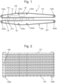
Figure 1 shows a side view of a leak detection system according to an embodiment; -
Figure 2 shows a top view of the leak detection system shown inFigure 1 ; -
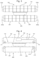
Figure 3 shows an end view of the leak detection system shown inFigures 1 and 2 ; -
Figure 4 shows an end view of the leak detection system shown inFigures 1 to 3 with the conveyor belts being omitted to reveal the positioning of the optical sensors; and -
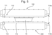
Figure 5 shows an end view of a second leak detection with the conveyor belts being omitted to reveal the positioning of the optical sensors. - A first embodiment of a leak detection system will now be described with reference to
Figures 1-4 . - The leak detection system 1 comprises first and second opposing
conveyors systems upper conveyor 100 comprises aconveyor belt 101 entrained about a series ofrollers drive rollers conveyor 100 and determine the length of the conveyor, whileauxiliary rollers conveyor belt 101. In particular, theconveyor belt 101 is entrained about therollers drive rollers drive rollers auxiliary rollers conveyor belt 101, and provides space for internal components, which will be discussed further below. While only these rollers are shown in this embodiment, it will be appreciated that additional entraining rollers may be provided as required for supporting and maintaining the shape of the conveyor belt. - The
second conveyor 200 similarly comprises aconveyor belt 201 entrained aboutrollers second drive rollers conveyor 200 and determine the length of the conveyor. Therollers second conveyor 200 with a substantially flat upper surface, while theauxiliary rollers conveyor 200 may support items being conveyed through the system, additional rollers along the length of the conveyor supporting the upper surface of theconveyor belt 201 may be required. - As mentioned above, the
conveyors upper conveyor 100 and the flat upper surface of thelower conveyor 200 provide that a gap of substantially constant height is defined between the two opposingconveyor systems tray 10 is conveyed towards the leak detection system 1 by an upstream conveyor (not shown) such that the tray enters between the opposingconveyors conveyors drive rollers belts 101, 102 act to convey atray 10 through the system. This movement of the twoconveyor belts tray 10 to be drawn into the gap between the twoconveyors - As shown in
Figure 2 , thefirst conveyor belt 101 comprises a series of openings through the belt in the form of an array ofslots 103. Theseslots 103 permit gas to pass through theconveyor belt surface 101. In particular, as thetray 10 is compressed, the modified atmosphere located within the tray may leak through a breach in the container and be allowed to pass through one of theslots 103. While not shown, thesecond conveyor system 200 similarly includes aconveyor belt 201 with a similar array of openings for permitting the permeation of gas. - As shown in
Figure 3 , eachconveyor belt ridges Figure 3 , these projectingridges conveyor belts tray 10. This minimisation of contact area ensures that the surface of theconveyor belt 101, 102 does not inadvertently block any breaches in the sealedfood containers 10. - As shown in
Figures 1 and4 , the first andsecond conveyor systems optical sensor respective conveyor bels optical sensors 110, 120 are located towards the upstream end of the conveyor. This ensures that, as thecontainer 10 enters between the conveyors and is subject to applied pressure, the optical sensors are appropriately located to detect gas expelled before a significant amout of gas has escaped. This improves the sensitivity of the system. The firstoptical sensor 110, located in thefirst conveyor 100, comprises alight source 111 and adetector 112. Thelight source 111 may be a laser such as a diode laser or a semiconductor laser. The wavelength(s) or wavelength range selected for the light source should match the absorption spectra of at least one of the gases located inside the modifiedatmosphere tray 10. Preferably, the wavelength(s) should be selected to match the absorption spectra of the gas in the container whose proportion differs greatest from that of ambient air. Thedetector 112 may be any optical detector able to detect the wavelengths or wavelength range selected for thelight source 111 and may be, for example, a photo diode, a photo multiplier, a CCD detector, a CMOS detector or an InGaAs detector. - The
light source 111 is arranged at one lateral edge of the conveyor and is configured to transmit alight signal 113 across the width of theconveyor 100 to thedetector 112 located at the opposite lateral edge of the conveyor. Thelight source 111 anddetector 112 are arranged proximate the lower surface of theconveyor belt 101 so that the transmitted light 113 will pass as close as possible to atray 10 as it passes between theconveyors light source 111 is arranged at one lateral side of theconveyor 100 and thedetector 112 is located at the opposite lateral side of theconveyor 100 so that thelight signal 113 extends across substantially the entire width of theconveyor 100 to provide maximum coverage and to accommodate trays entering at different lateral positions. - As mentioned above, the
second conveyor 200 also includes anoptical sensor 210 which, as with the firstoptical sensor 110, comprises alight source 211 at one lateral side of the conveyor and adetector 212 at the opposing lateral side of the conveyor, such that thelight source 211 transmits alight signal 213 across substantially the entire width of theconveyor 200. In this embodiment, the secondlight source 211 and thesecond detector 212 are arranged such that thelight signal 213 extends along a path proximate the upper surface of thelower conveyor belt 200. Again, arranging theoptical sensor 210 in this manner ensures that the light signal is as close as possible to atray 10 as it passes between theconveyors - In use, as a
tray 10 is conveyed through the leak detection system 1 between the opposingconveyors tray 10 passes between theoptical sensors conveyor belts 101 or 102 through the openings and impinge upon thelight signal optical sensors detector - Both the first and second
optical sensors control unit 20 byrespective wires control unit 20 is located within the upper conveyor and the wire connecting to the second optical sensor 120 extends out of the side of theupper conveyor 100, before being routed down and into the side of thesecond conveyor 200 to connect to the secondoptical sensor 210. In other embodiments, the control unit could be located outside of both conveyors. The control unit is connected to thedetectors optical sensors control unit 20 may determine that there is a breach in the sealedfood container 10 once a threshold value for CO2 is exceeded, or when a certain rate of change of CO2 is detected, if the container has a modified atmosphere rich in CO2. - Not only will this embodiment allow for detection of breaches, but it may also be used to infer a type of upstream failure. In particular, this system may distinguish between a breach in the top of the container or in the bottom of the container. For example, only the first
optical sensor 110 may detect a variation in gas composition, in which case it may be inferred that the breach is in the top of the container. Alternatively, the signals between the twooptical sensors control unit 20 to determine which sensor detected the largest spike or drop in intensity, with the greater change being indicative of the breach being closer to said sensor. If, for example, an unusually high proportion of breaches are being detected in either the top or bottom of the container, this may be used to deduce that there is a particular type of upstream problem. For example, regularly breached container bottoms may be indicative of a problem with the lower traysealing tool or tray former. Alternatively, a high proportion of breaches in the tops of containers may be used to deduce a problem with the upper traysealing tool or with the film real. - Furthermore, in combination with information concerning the location of the container, this embodiment may be used to determine the location of the breach along the conveying direction of the container. For example, a light gate (not shown) may be arranged to detect a container passing between the first and second
optical sensors control unit 20 and compared with the signals from theoptical sensors - An alternative optical sensor arrangement is shown in
Figure 5 . In this embodiment, only oneoptical sensor 110 is provided. In this embodiment, the optical sensor comprises alight source 111 located within theupper conveyor 100 and adetector 112 located in thelower conveyor 200. Thelight source 111 is located at one lateral edge of the conveyor and transmits alight signal 113, which travels along the width of theupper conveyor 100 and passes out the opposite lateral side of theconveyor 100. First andsecond mirrors second conveyor 200, i.e. between the upper and lower surfaces of thebelt 201. The light signal travels across substantially the entire width of thissecond conveyor 200 and is received on adetector 112. Thelight source 111 is provided close to the lower surface of theupper conveyor belt 101 and the detector is located close to the upper surface of thelower conveyor belt 201 such that thelight signal 113 will pass close to both the upper and lower surfaces of atray 10 passing between theconveyors conveyors tray 10. - In
Figure 5 , the control unit is not shown so that the arrangement of the light signal can be more clearly seen, but the control unit may be arranged inside thelower conveyor 200 and connected to thedetector 112, for example.
Claims (15)
- A leak detection system (1) for detecting breaches in sealed food containers, the leak detection system comprising:a first optical sensor (110) configured to transmit a light signal (113) across a first testing path, said first optical sensor being sensitive to gas composition variations; and characterised bya permeable pressing member (100) configured to, in use, apply pressure to the sealed food container;wherein said first optical sensor (110) is arranged such that at least a portion of the first testing path along which the light signal (113) is transmitted is located behind the permeable pressing member (100) relative to the side of the pressing member configured to come into contact with the sealed food container or is located within the permeable pressing member (100).
- A leak detection system according to claim 1, further comprising a conveyor (200) for conveying a sealed food container through the leak detection system, wherein preferably the permeable pressing member (100) is adjustably mounted over the conveyor (200) such that a distance between the pressing member (100) and the conveyor (200) may be varied in order to accommodate different dimensions of sealed food containers.
- A leak detection system according to any of the preceding claims, wherein the permeable pressing member (100) is configured to apply pressure to the sealed food container while said sealed food container moves through the leak detection system.
- A leak detection system according to claim 2 and claim 3, wherein the permeable pressing member (100) is arranged opposite the conveyor (200) such that a sealed food contained may pass between the permeable pressing member and the conveyor.
- A leak detection system according to any of the preceding claims, further comprising a control unit (20) coupled to the first optical sensor (110), the control unit receiving a signal of the first optical sensor (110) and determining the presence of a breach in a sealed food container based on the signal of the first optical sensor (110), wherein preferably the control unit (20) is configured to determine a magnitude of a breach based on the signal of the first optical sensor (110).
- A leak detection system according to claim 5 when dependent on claim 3 or claim 4, wherein the control unit (20) is configured to receive information concerning the location of the sealed food container relative to the first optical sensor (110), wherein the control unit (20) is configured to determine the location of a breach in the sealed food container based on the signal of the first optical sensor and the information concerning the location of the sealed food container.
- A leak detection system according to any of the preceding claims, wherein the permeable pressing member (100) comprises a first permeable conveyor belt (101), wherein preferably the first permeable conveyor belt (101) comprises an array of openings (103) through the conveyor belt (101) for permitting gas to permeate through the conveyor belt (101).
- A leak detection system according to claim 7, wherein the first permeable conveyor belt (101) comprises an array of elements (104) that project away from the surface of the conveyor belt (101) for contacting the sealed food container and separating a body of the conveyor belt (101) from the surface of the sealed food container.
- A leak detection system according to any of claims 7 to 8, wherein the first optical sensor (110) is arranged such that at least a portion of the first testing path is located within the first conveyor belt (101) and extends across the width of the conveyor belt.
- A leak detection system according to at least claim 2, wherein the conveyor (200) is a permeable conveyor, and wherein the first optical sensor (110) or a second optical sensor (210) sensitive to gas composition variations is configured to transmit a second light signal across a second testing path, wherein said optical sensor is arranged such that at least a portion of the second testing path along which the second light signal is transmitted is located behind the permeable conveyor relative to the side of the permeable conveyor configured to come into contact with the sealed food container or is located within the permeable conveyor (200), wherein preferably the permeable conveyor (200) comprises a second permeable conveyor belt (201), and wherein further preferably said optical sensor (110, 210) is arranged such that at least a portion of the second testing path is located within the second permeable conveyor belt (201) and extends across the width of said conveyor belt.
- A leak detection system according to claim 10, wherein a second optical sensor (210) sensitive to gas composition variations is configured to transmit the second light signal (213) across the second testing path, wherein the first optical sensor (110) is sensitive to gas composition variations in the first testing path and the second optical sensor (210) is sensitive to gas composition variations in the second testing path.
- A leak detection system according to claim 11 when dependent on at least claim 5, wherein the control unit (20) is coupled to the second optical sensor (210) and is configured to receive a signal from the second optical sensor (210), wherein the control unit is configured to determine the location of a breach based on the signal from the first optical sensor (110) and the signal from the second optical sensor (210), wherein preferably the control unit (20) is configured to determine the location of a breach by comparing the signal from the first optical sensor and the signal from the second optical sensor.
- A leak detection system according to any of the preceding claims, wherein the first optical sensor (110) is mounted to said permeable pressing member (100).
- A leak detection system according to any of the preceding claims, wherein the optical sensor(s) (110, 210) comprise one or more light sources (111, 211), preferably a laser, configured to transmit the light signal and wherein each optical sensor comprises a detector (112, 212) sensitive to the light signal transmitted by said light source.
- A method of detecting breaches in sealed food containers, the method comprising:applying pressure to a sealed food container using a permeable pressing member (100);detecting a variation in gas composition behind or within the permeable pressing member (100) using a first optical sensor (110) configured to transmit a light signal (113) across a first testing path;wherein said first optical sensor (110) is arranged such that at least a portion of the first testing path along which the light signal (113) is transmitted is located behind the permeable pressing member (100) relative to the side of the pressing member configured to come into contact with the sealed food container or is located within the permeable pressing member (100).
Applications Claiming Priority (2)
| Application Number | Priority Date | Filing Date | Title |
|---|---|---|---|
| GBGB2001029.4A GB202001029D0 (en) | 2020-01-24 | 2020-01-24 | System and method for detecting breaches in containers |
| PCT/GB2021/050130 WO2021148790A1 (en) | 2020-01-24 | 2021-01-21 | System and method for detecting breaches in containers |
Publications (3)
| Publication Number | Publication Date |
|---|---|
| EP4094067A1 EP4094067A1 (en) | 2022-11-30 |
| EP4094067C0 EP4094067C0 (en) | 2025-02-12 |
| EP4094067B1 true EP4094067B1 (en) | 2025-02-12 |
Family
ID=69725971
Family Applications (1)
| Application Number | Title | Priority Date | Filing Date |
|---|---|---|---|
| EP21702071.8A Active EP4094067B1 (en) | 2020-01-24 | 2021-01-21 | System and method for detecting breaches in containers |
Country Status (7)
| Country | Link |
|---|---|
| US (1) | US12352660B2 (en) |
| EP (1) | EP4094067B1 (en) |
| JP (1) | JP7819104B2 (en) |
| CN (1) | CN115210554A (en) |
| ES (1) | ES3014826T3 (en) |
| GB (1) | GB202001029D0 (en) |
| WO (1) | WO2021148790A1 (en) |
Family Cites Families (12)
| Publication number | Priority date | Publication date | Assignee | Title |
|---|---|---|---|---|
| WO2001029528A2 (en) * | 1999-10-19 | 2001-04-26 | Benthos, Inc. | Multiple sensor in-line container inspection |
| GB0208100D0 (en) | 2002-04-09 | 2002-05-22 | Univ Strathclyde | Semiconductor diode laser spectrometer arrangement |
| JP2007108101A (en) * | 2005-10-17 | 2007-04-26 | Takachiho Seiki Kk | Leakage inspection device of sealed object |
| US9228938B2 (en) * | 2009-06-29 | 2016-01-05 | Hager Environmental And Atmospheric Technologies, Llc | Method and device for remote sensing of amount of ingredients and temperature of gases |
| EP2686657B1 (en) * | 2011-03-16 | 2019-11-27 | Norden Machinery Ab | Method and arrangement for leak detection |
| CA2961453A1 (en) * | 2014-09-30 | 2016-04-07 | Ft System S.R.L. | Group and method for measuring the pressure in closed containers |
| CN106331442B (en) | 2015-07-02 | 2021-01-15 | 松下知识产权经营株式会社 | Image pickup apparatus |
| US10830660B2 (en) * | 2015-10-14 | 2020-11-10 | Cascade Technologies Holdings Limited | Leak detection of gas containers using an optical detector |
| GB2549985B (en) | 2016-05-06 | 2020-01-08 | Ishida Europe Ltd | Container leak detection |
| US11340161B2 (en) * | 2017-04-28 | 2022-05-24 | Gasporox Ab | Compact multi-wavelength TDLAS system |
| SE541253C2 (en) | 2017-10-18 | 2019-05-14 | Gasporox Ab | System and method for determining the integrity of containers by optical measurement |
| JP2022503320A (en) | 2018-03-06 | 2022-01-12 | ガスポロックス エービー | Systems and methods for determining container integrity |
-
2020
- 2020-01-24 GB GBGB2001029.4A patent/GB202001029D0/en not_active Ceased
-
2021
- 2021-01-21 WO PCT/GB2021/050130 patent/WO2021148790A1/en not_active Ceased
- 2021-01-21 US US17/794,880 patent/US12352660B2/en active Active
- 2021-01-21 CN CN202180017174.7A patent/CN115210554A/en active Pending
- 2021-01-21 JP JP2022545085A patent/JP7819104B2/en active Active
- 2021-01-21 EP EP21702071.8A patent/EP4094067B1/en active Active
- 2021-01-21 ES ES21702071T patent/ES3014826T3/en active Active
Also Published As
| Publication number | Publication date |
|---|---|
| EP4094067C0 (en) | 2025-02-12 |
| US12352660B2 (en) | 2025-07-08 |
| JP7819104B2 (en) | 2026-02-24 |
| EP4094067A1 (en) | 2022-11-30 |
| CN115210554A (en) | 2022-10-18 |
| ES3014826T3 (en) | 2025-04-25 |
| JP2023513445A (en) | 2023-03-31 |
| US20230076074A1 (en) | 2023-03-09 |
| GB202001029D0 (en) | 2020-03-11 |
| WO2021148790A1 (en) | 2021-07-29 |
Similar Documents
| Publication | Publication Date | Title |
|---|---|---|
| US10690564B2 (en) | Container leak detection | |
| EP1222449B1 (en) | Multiple sensor in-line container inspection | |
| EP3969871B1 (en) | Method and apparatus for recognizing the presence of leakages from sealed containers | |
| SE541253C2 (en) | System and method for determining the integrity of containers by optical measurement | |
| JP2021067634A (en) | Device for measuring gas concentration in packaging bag | |
| JP7505732B2 (en) | Gas concentration measuring device for packaging bags | |
| US12352660B2 (en) | System and method for detecting breaches in containers | |
| US6955256B2 (en) | Conveyor | |
| JP2004003899A (en) | Method and apparatus of visual inspection of packed foodstuff or the like | |
| KR102111369B1 (en) | Image Correction TerahertzWave Object Inspection Apparatus | |
| NL1028103C2 (en) | Density determination of packaging. | |
| JP7607919B2 (en) | Gas concentration measurement method for pillow packaging bags | |
| JP7343169B2 (en) | Gas concentration measurement method and gas concentration measurement device for sealed packaging containers | |
| JP5145030B2 (en) | Sheet flap bending state inspection device | |
| CN1119235C (en) | Method and device for checking material strip width | |
| US6878103B2 (en) | Controlling cuts in an inner liner for a group of cigarettes | |
| JP7696606B2 (en) | Laser gas concentration measuring device | |
| KR20060127956A (en) | Method and assembly for checking overlapping flat items | |
| US20080245463A1 (en) | Glue application detection system and method | |
| JP2003149074A (en) | Seal check device | |
| RU2798257C2 (en) | System and method for determining integrity of containers by optical measurement | |
| JP2021067633A (en) | Method of measuring gas concentration in packaging bag | |
| Cocola et al. | TDLAS OXYGEN SENSOR FOR MEASUREMENT ON FLOW-PACKED PRODUCTS | |
| JPS5892932A (en) | Detecting system for gaseous material |
Legal Events
| Date | Code | Title | Description |
|---|---|---|---|
| STAA | Information on the status of an ep patent application or granted ep patent |
Free format text: STATUS: UNKNOWN |
|
| STAA | Information on the status of an ep patent application or granted ep patent |
Free format text: STATUS: THE INTERNATIONAL PUBLICATION HAS BEEN MADE |
|
| PUAI | Public reference made under article 153(3) epc to a published international application that has entered the european phase |
Free format text: ORIGINAL CODE: 0009012 |
|
| STAA | Information on the status of an ep patent application or granted ep patent |
Free format text: STATUS: REQUEST FOR EXAMINATION WAS MADE |
|
| 17P | Request for examination filed |
Effective date: 20220624 |
|
| AK | Designated contracting states |
Kind code of ref document: A1 Designated state(s): AL AT BE BG CH CY CZ DE DK EE ES FI FR GB GR HR HU IE IS IT LI LT LU LV MC MK MT NL NO PL PT RO RS SE SI SK SM TR |
|
| DAV | Request for validation of the european patent (deleted) | ||
| DAX | Request for extension of the european patent (deleted) | ||
| GRAP | Despatch of communication of intention to grant a patent |
Free format text: ORIGINAL CODE: EPIDOSNIGR1 |
|
| STAA | Information on the status of an ep patent application or granted ep patent |
Free format text: STATUS: GRANT OF PATENT IS INTENDED |
|
| INTG | Intention to grant announced |
Effective date: 20240912 |
|
| GRAS | Grant fee paid |
Free format text: ORIGINAL CODE: EPIDOSNIGR3 |
|
| GRAA | (expected) grant |
Free format text: ORIGINAL CODE: 0009210 |
|
| STAA | Information on the status of an ep patent application or granted ep patent |
Free format text: STATUS: THE PATENT HAS BEEN GRANTED |
|
| AK | Designated contracting states |
Kind code of ref document: B1 Designated state(s): AL AT BE BG CH CY CZ DE DK EE ES FI FR GB GR HR HU IE IS IT LI LT LU LV MC MK MT NL NO PL PT RO RS SE SI SK SM TR |
|
| REG | Reference to a national code |
Ref country code: GB Ref legal event code: FG4D |
|
| REG | Reference to a national code |
Ref country code: CH Ref legal event code: EP |
|
| REG | Reference to a national code |
Ref country code: DE Ref legal event code: R096 Ref document number: 602021025975 Country of ref document: DE |
|
| REG | Reference to a national code |
Ref country code: IE Ref legal event code: FG4D |
|
| U01 | Request for unitary effect filed |
Effective date: 20250214 |
|
| U07 | Unitary effect registered |
Designated state(s): AT BE BG DE DK EE FI FR IT LT LU LV MT NL PT RO SE SI Effective date: 20250224 |
|
| REG | Reference to a national code |
Ref country code: ES Ref legal event code: FG2A Ref document number: 3014826 Country of ref document: ES Kind code of ref document: T3 Effective date: 20250425 |
|
| PG25 | Lapsed in a contracting state [announced via postgrant information from national office to epo] |
Ref country code: RS Free format text: LAPSE BECAUSE OF FAILURE TO SUBMIT A TRANSLATION OF THE DESCRIPTION OR TO PAY THE FEE WITHIN THE PRESCRIBED TIME-LIMIT Effective date: 20250512 |
|
| PG25 | Lapsed in a contracting state [announced via postgrant information from national office to epo] |
Ref country code: PL Free format text: LAPSE BECAUSE OF FAILURE TO SUBMIT A TRANSLATION OF THE DESCRIPTION OR TO PAY THE FEE WITHIN THE PRESCRIBED TIME-LIMIT Effective date: 20250212 |
|
| PG25 | Lapsed in a contracting state [announced via postgrant information from national office to epo] |
Ref country code: NO Free format text: LAPSE BECAUSE OF FAILURE TO SUBMIT A TRANSLATION OF THE DESCRIPTION OR TO PAY THE FEE WITHIN THE PRESCRIBED TIME-LIMIT Effective date: 20250512 Ref country code: IS Free format text: LAPSE BECAUSE OF FAILURE TO SUBMIT A TRANSLATION OF THE DESCRIPTION OR TO PAY THE FEE WITHIN THE PRESCRIBED TIME-LIMIT Effective date: 20250612 |
|
| PG25 | Lapsed in a contracting state [announced via postgrant information from national office to epo] |
Ref country code: HR Free format text: LAPSE BECAUSE OF FAILURE TO SUBMIT A TRANSLATION OF THE DESCRIPTION OR TO PAY THE FEE WITHIN THE PRESCRIBED TIME-LIMIT Effective date: 20250212 |
|
| PG25 | Lapsed in a contracting state [announced via postgrant information from national office to epo] |
Ref country code: GR Free format text: LAPSE BECAUSE OF FAILURE TO SUBMIT A TRANSLATION OF THE DESCRIPTION OR TO PAY THE FEE WITHIN THE PRESCRIBED TIME-LIMIT Effective date: 20250513 |
|
| PG25 | Lapsed in a contracting state [announced via postgrant information from national office to epo] |
Ref country code: SM Free format text: LAPSE BECAUSE OF FAILURE TO SUBMIT A TRANSLATION OF THE DESCRIPTION OR TO PAY THE FEE WITHIN THE PRESCRIBED TIME-LIMIT Effective date: 20250212 |
|
| PG25 | Lapsed in a contracting state [announced via postgrant information from national office to epo] |
Ref country code: CZ Free format text: LAPSE BECAUSE OF FAILURE TO SUBMIT A TRANSLATION OF THE DESCRIPTION OR TO PAY THE FEE WITHIN THE PRESCRIBED TIME-LIMIT Effective date: 20250212 |
|
| PG25 | Lapsed in a contracting state [announced via postgrant information from national office to epo] |
Ref country code: SK Free format text: LAPSE BECAUSE OF FAILURE TO SUBMIT A TRANSLATION OF THE DESCRIPTION OR TO PAY THE FEE WITHIN THE PRESCRIBED TIME-LIMIT Effective date: 20250212 |
|
| PLBE | No opposition filed within time limit |
Free format text: ORIGINAL CODE: 0009261 |
|
| STAA | Information on the status of an ep patent application or granted ep patent |
Free format text: STATUS: NO OPPOSITION FILED WITHIN TIME LIMIT |
|
| PGFP | Annual fee paid to national office [announced via postgrant information from national office to epo] |
Ref country code: GB Payment date: 20251127 Year of fee payment: 6 |
|
| U20 | Renewal fee for the european patent with unitary effect paid |
Year of fee payment: 6 Effective date: 20251205 |
|
| 26N | No opposition filed |
Effective date: 20251113 |
|
| PGFP | Annual fee paid to national office [announced via postgrant information from national office to epo] |
Ref country code: ES Payment date: 20260212 Year of fee payment: 6 |