EP4093996B1 - Process control systems and associated monoflanges - Google Patents
Process control systems and associated monoflanges Download PDFInfo
- Publication number
- EP4093996B1 EP4093996B1 EP21705381.8A EP21705381A EP4093996B1 EP 4093996 B1 EP4093996 B1 EP 4093996B1 EP 21705381 A EP21705381 A EP 21705381A EP 4093996 B1 EP4093996 B1 EP 4093996B1
- Authority
- EP
- European Patent Office
- Prior art keywords
- monoflange
- valve
- bleed
- bonnet
- block valve
- Prior art date
- Legal status (The legal status is an assumption and is not a legal conclusion. Google has not performed a legal analysis and makes no representation as to the accuracy of the status listed.)
- Active
Links
Images


Classifications
-
- F—MECHANICAL ENGINEERING; LIGHTING; HEATING; WEAPONS; BLASTING
- F16—ENGINEERING ELEMENTS AND UNITS; GENERAL MEASURES FOR PRODUCING AND MAINTAINING EFFECTIVE FUNCTIONING OF MACHINES OR INSTALLATIONS; THERMAL INSULATION IN GENERAL
- F16K—VALVES; TAPS; COCKS; ACTUATING-FLOATS; DEVICES FOR VENTING OR AERATING
- F16K11/00—Multiple-way valves, e.g. mixing valves; Pipe fittings incorporating such valves
- F16K11/10—Multiple-way valves, e.g. mixing valves; Pipe fittings incorporating such valves with two or more closure members not moving as a unit
- F16K11/20—Multiple-way valves, e.g. mixing valves; Pipe fittings incorporating such valves with two or more closure members not moving as a unit operated by separate actuating members
- F16K11/22—Multiple-way valves, e.g. mixing valves; Pipe fittings incorporating such valves with two or more closure members not moving as a unit operated by separate actuating members with an actuating member for each valve, e.g. interconnected to form multiple-way valves
-
- F—MECHANICAL ENGINEERING; LIGHTING; HEATING; WEAPONS; BLASTING
- F16—ENGINEERING ELEMENTS AND UNITS; GENERAL MEASURES FOR PRODUCING AND MAINTAINING EFFECTIVE FUNCTIONING OF MACHINES OR INSTALLATIONS; THERMAL INSULATION IN GENERAL
- F16K—VALVES; TAPS; COCKS; ACTUATING-FLOATS; DEVICES FOR VENTING OR AERATING
- F16K1/00—Lift valves or globe valves, i.e. cut-off apparatus with closure members having at least a component of their opening and closing motion perpendicular to the closing faces
- F16K1/02—Lift valves or globe valves, i.e. cut-off apparatus with closure members having at least a component of their opening and closing motion perpendicular to the closing faces with screw-spindle
- F16K1/04—Lift valves or globe valves, i.e. cut-off apparatus with closure members having at least a component of their opening and closing motion perpendicular to the closing faces with screw-spindle with a cut-off member rigid with the spindle, e.g. main valves
-
- F—MECHANICAL ENGINEERING; LIGHTING; HEATING; WEAPONS; BLASTING
- F16—ENGINEERING ELEMENTS AND UNITS; GENERAL MEASURES FOR PRODUCING AND MAINTAINING EFFECTIVE FUNCTIONING OF MACHINES OR INSTALLATIONS; THERMAL INSULATION IN GENERAL
- F16K—VALVES; TAPS; COCKS; ACTUATING-FLOATS; DEVICES FOR VENTING OR AERATING
- F16K1/00—Lift valves or globe valves, i.e. cut-off apparatus with closure members having at least a component of their opening and closing motion perpendicular to the closing faces
- F16K1/14—Lift valves or globe valves, i.e. cut-off apparatus with closure members having at least a component of their opening and closing motion perpendicular to the closing faces with ball-shaped valve member
-
- F—MECHANICAL ENGINEERING; LIGHTING; HEATING; WEAPONS; BLASTING
- F16—ENGINEERING ELEMENTS AND UNITS; GENERAL MEASURES FOR PRODUCING AND MAINTAINING EFFECTIVE FUNCTIONING OF MACHINES OR INSTALLATIONS; THERMAL INSULATION IN GENERAL
- F16K—VALVES; TAPS; COCKS; ACTUATING-FLOATS; DEVICES FOR VENTING OR AERATING
- F16K11/00—Multiple-way valves, e.g. mixing valves; Pipe fittings incorporating such valves
- F16K11/10—Multiple-way valves, e.g. mixing valves; Pipe fittings incorporating such valves with two or more closure members not moving as a unit
- F16K11/105—Three-way check or safety valves with two or more closure members
-
- F—MECHANICAL ENGINEERING; LIGHTING; HEATING; WEAPONS; BLASTING
- F16—ENGINEERING ELEMENTS AND UNITS; GENERAL MEASURES FOR PRODUCING AND MAINTAINING EFFECTIVE FUNCTIONING OF MACHINES OR INSTALLATIONS; THERMAL INSULATION IN GENERAL
- F16K—VALVES; TAPS; COCKS; ACTUATING-FLOATS; DEVICES FOR VENTING OR AERATING
- F16K17/00—Safety valves; Equalising valves, e.g. pressure relief valves
- F16K17/02—Safety valves; Equalising valves, e.g. pressure relief valves opening on surplus pressure on one side; closing on insufficient pressure on one side
-
- F—MECHANICAL ENGINEERING; LIGHTING; HEATING; WEAPONS; BLASTING
- F16—ENGINEERING ELEMENTS AND UNITS; GENERAL MEASURES FOR PRODUCING AND MAINTAINING EFFECTIVE FUNCTIONING OF MACHINES OR INSTALLATIONS; THERMAL INSULATION IN GENERAL
- F16K—VALVES; TAPS; COCKS; ACTUATING-FLOATS; DEVICES FOR VENTING OR AERATING
- F16K27/00—Construction of housing; Use of materials therefor
- F16K27/003—Housing formed from a plurality of the same valve elements
-
- F—MECHANICAL ENGINEERING; LIGHTING; HEATING; WEAPONS; BLASTING
- F16—ENGINEERING ELEMENTS AND UNITS; GENERAL MEASURES FOR PRODUCING AND MAINTAINING EFFECTIVE FUNCTIONING OF MACHINES OR INSTALLATIONS; THERMAL INSULATION IN GENERAL
- F16K—VALVES; TAPS; COCKS; ACTUATING-FLOATS; DEVICES FOR VENTING OR AERATING
- F16K27/00—Construction of housing; Use of materials therefor
- F16K27/02—Construction of housing; Use of materials therefor of lift valves
- F16K27/0245—Construction of housing; Use of materials therefor of lift valves with ball-shaped valve members
-
- F—MECHANICAL ENGINEERING; LIGHTING; HEATING; WEAPONS; BLASTING
- F16—ENGINEERING ELEMENTS AND UNITS; GENERAL MEASURES FOR PRODUCING AND MAINTAINING EFFECTIVE FUNCTIONING OF MACHINES OR INSTALLATIONS; THERMAL INSULATION IN GENERAL
- F16K—VALVES; TAPS; COCKS; ACTUATING-FLOATS; DEVICES FOR VENTING OR AERATING
- F16K27/00—Construction of housing; Use of materials therefor
- F16K27/02—Construction of housing; Use of materials therefor of lift valves
- F16K27/0263—Construction of housing; Use of materials therefor of lift valves multiple way valves
-
- F—MECHANICAL ENGINEERING; LIGHTING; HEATING; WEAPONS; BLASTING
- F16—ENGINEERING ELEMENTS AND UNITS; GENERAL MEASURES FOR PRODUCING AND MAINTAINING EFFECTIVE FUNCTIONING OF MACHINES OR INSTALLATIONS; THERMAL INSULATION IN GENERAL
- F16K—VALVES; TAPS; COCKS; ACTUATING-FLOATS; DEVICES FOR VENTING OR AERATING
- F16K31/00—Actuating devices; Operating means; Releasing devices
- F16K31/44—Mechanical actuating means
- F16K31/60—Handles
-
- G—PHYSICS
- G01—MEASURING; TESTING
- G01L—MEASURING FORCE, STRESS, TORQUE, WORK, MECHANICAL POWER, MECHANICAL EFFICIENCY, OR FLUID PRESSURE
- G01L19/00—Details of, or accessories for, apparatus for measuring steady or quasi-steady pressure of a fluent medium insofar as such details or accessories are not special to particular types of pressure gauges
- G01L19/0007—Fluidic connecting means
Definitions
- the present patent relates generally to process control systems and, in particular, to process control systems and associated monoflanges.
- Process control systems may include fluidic lines and different fluidic connections.
- Process control valves may be used to control fluid flow between the fluidic lines.
- non-destructive testing may be performed on welded joints between the fluidic lines and the process control valves.
- Document US 2013/092249 A1 discloses method and apparatus for unplugging hydrocarbon drains or vents including a fluidic line, a primary valve and several connected valves.
- Swagelok discloses: "Instrument Manifold Systems Instrument, Direct, and Remote-Mount Manifolds and Modular Systems", 1 February 2015 (2015-02-01), pages 1-32, XP055287593, retrieved from the Internet: URL:http://www.swagelok.de/downloads/WebCatalogs/EN/MS-02-445.pdf, [retrieved on 2016-07-12 ].
- Another document discloses: “ Double Block and Bleed with Ultra-Low Emission options", 31 December 2008 (2008-12-31), XP055273749, retrieved from the Internet: URL: http://www.parker.com/literature/Instrumentation Products Division Europe/Cat 4190_FP.pdf, [retrieved on 2016-05-19 ].
- a process control system includes a fluidic line having a longitudinal axis and including a fluidic connection having an axis angled relative to the longitudinal axis of the fluidic line.
- the process control system includes a primary block valve having an inlet port and an outlet port. The inlet port is coupled to the fluidic connection.
- the process control system includes a monoflange including a male portion forming an inlet port and including an external threaded surface.
- the monoflange includes an outlet and a flanged interface surrounding the outlet port of the monoflange.
- the monoflange includes a bleed port.
- the monoflange includes a bleed valve adapted to control fluid flow from the bleed port and a secondary block valve adapted to control fluid flow from the outlet port.
- the external threaded surface of the male portion threadably engages the outlet port of the primary block valve.
- a method includes threadably engaging an outlet port of a primary block valve with an external threaded surface of a male portion of a monoflange.
- the primary block valve has an inlet port coupled to a fluidic connection of a fluidic line.
- the monoflange includes the male portion forming an inlet port, a flanged interface surrounding an outlet port of the monoflange, and a bleed port.
- the monoflange further includes a bleed valve and a secondary block valve. The method includes actuating the secondary block valve to control fluid flow from the outlet port and actuating the bleed valve to control fluid flow from the bleed port.
- an apparatus and/or method may further include any one or more of the following:
- the primary block valve, the secondary block valve, and the bleed valve enable double block and bleed functionality.
- the secondary block valve is positioned between the male portion forming the inlet port and the bleed valve.
- the bleed valve is positioned between the flanged interface surrounding the outlet port and the secondary block valve.
- the monoflange includes an integral body.
- the integral body includes a one-piece forged valve body.
- At least one of the secondary block valve or the bleed valve includes a bonnet having a bonnet flange and the monoflange includes an external monoflange surface adjacent the corresponding bonnet. Further including a seal surrounding the bonnet and positioned between the bonnet flange and the external monoflange surface.
- the secondary block valve and, optionally, the bleed valve include a bonnet having a central bore, external threads, and a distal portion.
- a stem assembly is disposed within the central bore.
- a body of the monoflange includes a threaded bore, a valve seat, and a portion surrounding the valve seat. The external threads of the bonnet threadably engage the threaded bore and the distal portion sealingly engages the portion surrounding the valve seat.
- At least one of the secondary block valve or the bleed valve includes a bonnet, a plug, and a stem assembly including a first portion that threadably engages the bonnet and a second portion that carries the plug and is rotationally coupled to the first portion.
- the first portion includes slot and the second portion includes a head that is disposed within the slot.
- closing the secondary block valve prevents additional process fluid flow through the secondary block valve and toward the bleed valve.
- the bleed valve and the secondary block valve are positioned in a vertical plane relative to one another.
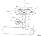
- Fig. 1 illustrates a process control system 100 assembled in accordance with a first disclosed example of the present invention.
- the process control system 100 may be used in association with oil production industries, refining industries, power generation industries, and/or chemical industries. Other applications may prove suitable.
- the process control system 100 includes a fluidic line 102, a primary block valve 104, and a monoflange 106.
- the monoflange 106 may act as a manifold.
- the primary block valve 104 and the monoflange 106 are adapted to provide double block and bleed functionality to the process control system 100.
- the primary block valve 104 may be referred to as a primary isolation valve. While the process control system 100 is shown in a vertical orientation, other configurations may prove suitable. For example, the process control system may be oriented in a horizontal orientation.
- the fluidic line 102 has a longitudinal axis 108 and includes a fluidic connection 110.
- the fluidic connection 110 is a T-connection having external threads 112.
- the fluidic connection 110 includes an axis 114 that is angled relative to the longitudinal axis 108 of the fluidic line 102.
- the axes 108, 114 are shown being substantially perpendicular relative to one another. However, the axes 108, 114 may be differently arranged. For example, the axes 108, 114 may be disposed at approximately 45° relative to one another.
- the primary block valve 104 includes an inlet port 116 and an outlet port 118.
- the inlet port 116 is coupled to the fluidic connection 110.
- the inlet port 116 has internal threads 120 that threadably engage the external threads 112 of the fluidic connection 110.
- the primary block valve 104 may be coupled to the fluidic connection 110 in different ways.
- the inlet port 116 of the primary block valve 104 may be welded to the fluidic connection 110.
- the outlet port 118 also includes internal threads 121 in the illustrated example.
- the primary block valve 104 is illustrated as a globe valve. However, the primary block valve 104 may be a different type of valve.
- the primary block valve 104 includes an actuator 122 formed as a hand wheel 124.
- the actuator 122 may be differently implemented.
- the monoflange 106 includes a male portion 126 and a flanged interface 128.
- the male portion 126 opposes the flanged interface 128.
- the male portion 126 may be formed as a boss.
- the male portion 126 forms an inlet port 130 (represented by dashed lines) and includes an external threaded surface 132 that threadably engages the outlet port 118 of the primary block valve 104.
- the threaded connection between the primary block valve 104 and the monoflange 106 couples the components together.
- the monoflange 106 can be easily fluidically coupled to the primary block valve 104 without requiring additional fluidic connections (e.g., piping) and/or without requiring a welded fluidic connection.
- a welded connection may not be present (or a number of welded connections may be reduced) in the process control system 100 as compared to some known process control systems, the disclosed examples may be field installed with less or no non-destructive testing taking place. While the above discloses threaded connections, one or more of the connections may be welded. However, other types of couplings may prove suitable.
- the flanged interface 128 surrounds an outlet port 134 of the monoflange 106 (the outlet port 134 is more clearly shown in Fig. 2 ).
- the outlet port 134 may be used to flow process fluid to another instrument, a bleed ring, and/or a diaphragm seal.
- the monoflange 106 also includes a bleed port 136 (represented by dashed lines) that may be used to bleed pressure and/or fluid from the process control system 100 during maintenance and/or another procedure. Additionally or alternatively, the outlet port 134 and/or the bleed port 136 may be adapted to be used as an instrument port, a calibration port, and/or to provide bleed ring functionality.
- the monoflange 106 also includes a bleed valve 138 and a secondary block valve 140.
- the bleed valve 138 and the secondary block valve 140 may be positioned in a vertical plane 141 relative to one another.
- the secondary block valve 140 may be referred to as a secondary isolation valve.
- the bleed valve 138 and/or the secondary block valve 140 may be outside screw and yoke (OS&Y) needle valves.
- OS&Y outside screw and yoke
- other types of valves may prove suitable.
- the secondary block valve 140 may be referred to as an isolation valve.
- the secondary block valve 140 may provide for a bubble-tight shut off.
- the bleed valve 138 may provide for a bubble-tight shut off.
- the bleed valve 138 is adapted to control fluid flow from the bleed port 136 and the secondary block valve 140 is adapted to control fluid flow from the outlet port 134.
- the monoflange 106 provides single block and bleed functionality.
- the monoflange 106 may be adapted to provide single block functionality, double block functionality, double block and bleed functionality, and/or single block and double bleed functionality.
- a corresponding number of valves and ports may be provided depending on the arrangement.
- the secondary block valve 140 is positioned between the male portion 126 forming the inlet port 130 and the bleed valve 138.
- the process control system 100 may be bleed after the secondary block valve 140 is closed.
- the bleed valve 138 is positioned between the flanged interface 128 surrounding the outlet port 134 and the secondary block valve 140.
- the monoflange 106 is shown including two outlet ports (e.g., the outlet port 134 and the bleed port 136), providing the monoflange 106 with a different number of outlet ports may prove suitable.
- the monoflange 106 may include a number of valves that corresponds to the number of outlet ports.
- the monoflange 106 includes a monoflange body 142.
- the monoflange body 142 may be integral.
- the monoflange body 142 may be a one-piece forged valve body. Forming the monoflange body 142 as an integral body and/or a one-pieced forged valve body may allow the monoflange 106 to be field installed without non-destructive testing taking place in the field.
- forming the monoflange body 142 as an integral body and/or a one-pieced forged valve body may reduce leak paths, may reduce the number of joints (e.g., less additional fluidic couplings / lines) within the process control system 100, may reduce an overall height 143 of the monoflange 106, and/or may reduce a weight of the monoflange 106. Because the monoflange 106 is relatively light, support brackets (e.g., additional support brackets) may not be used when installing the monoflange 106. Reducing the overall height of the monoflange 106 may provide the monoflange 106 with a relatively compact design and, thus, a reduced envelope size.
- a neck flange 144 is coupled to the flanged interface 128 of the monoflange 106.
- the neck flange 144 is coupled to the monoflange 106 using fasteners 146.
- the fasteners 146 are received in threaded bores 148 (the threaded bores 148 are more clearly shown in Fig. 2 ) of the monoflange body 142.
- Other components, such as instrumentation products, may be mounted (e.g., directly mounted) to the flanged interface 128.
- a layer 150 may be disposed between the neck flange 144 and the flanged interface 128.
- the layer 150 may be a gasket or a diaphragm seal.
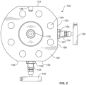
- Fig. 2 illustrates a plan view of the monoflange 106 of the process control system 100 of Fig. 1 .
- the bleed port 136 is positioned on a first side 151 of the monoflange body 142 and the secondary block valve 140 is positioned on a second side 152 of the monoflange body 142 opposite the first side 151.
- the bleed valve 138 is positioned on a third side 153 of the monoflange body 142.
- the third side 153 is positioned approximately 90° from the second side 152 on which the secondary block valve 140 is disposed. Other arrangements may prove suitable.
- the bleed valve 138 and the secondary block valve 140 include a bonnet 154.
- the bonnet 154 includes a hex 155 and the monoflange 106 has an external monoflange surface 156 adjacent the corresponding bonnet 154.
- the hex 155 may be used to secure the bonnet 154 within the body of the monoflange 106.
- a seal 157 surrounds the bonnet 154 and is positioned between the hex 155 and the external monoflange surface 156.
- the seal 157 may be adapted to prevent process fluid from flowing between the external monoflange surface 156 and the bonnet 154.
- the seal 157 may be an O-ring.
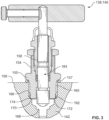
- Fig. 3 illustrates a cross-sectional view of an example implementation of at least one of the secondary block valve 140 or the bleed valve 138 that can be used with the monoflange 106 of the process control system 100 of Fig. 1 .
- the bonnet 154 includes a central bore 158, external threads 160, and a distal portion 162.
- a stem assembly 164 is disposed within the central bore 158 of the bonnet 154.
- the monoflange body 142 includes a threaded bore 166, a valve seat 168, and a portion 170 surrounding the valve seat 168.
- the valve seat 168 is formed by the monoflange body 142 and, thus, is integral to the monoflange body 142.
- the portion 170 may be a step including an inwardly tapered surface 172.
- the external threads 160 of the bonnet 154 threadably engage the threaded bore 166 of the monoflange body 142 and the distal portion 162 of the bonnet 154 sealingly engages the portion 170 surrounding the valve seat 168.
- An interface 174 between the distal portion 162 of the bonnet 154 and the portion 170 of the monoflange body 142 is a metal-to-metal seal.
- a gasket may be positioned between the distal portion 162 of the bonnet 154 and the portion 170 of the monoflange body 142.
- the interface 174 between the distal portion 162 and the portion 170 surrounding the valve seat 168 is spaced from the external threads 160 of the bonnet 154. As a result of the spacing, the external threads 160 may be isolated from the process fluid.
- Fig. 4 illustrates a cross-sectional view of another example implementation of at least one of the secondary block valve 140 or the bleed valve 138 that can be used with the monoflange 106 of the process control system 100 of Fig. 1 .
- the bonnet 154 includes the central bore 158 and the external threads 160.
- a central bore surface 176 defines the central bore 158 that includes internal bonnet threads 178 and defines a packing step 180.
- Packing 182 is disposed within the central bore 158 adjacent the packing step 180.
- a packing nut 184 is disposed within the central bore 158 and extends from the bonnet 154.
- the packing nut 184 includes external threads 186 that threadably engage the internal bonnet threads 178 of the central bore surface 178.
- the packing nut 184 includes a packing nut bore surface 188 that includes internal threads 190.
- the packing nut 184 is adapted to compress the packing 182 against the stem assembly 164.
- the stem assembly 164 is disposed within the central bore 158.
- the stem assembly 164 of Fig. 4 includes an upper stem portion 192 and a lower stem portion 194.
- the upper stem portion 192 is rotationally coupled to the lower stem portion 194.
- rotationally coupling the upper stem portion 192 and the lower stem portion 194 allows rotational movement of the upper stem portion 192 to not correspondingly rotate (or minimally rotate) the lower stem portion 194.
- the upper stem portion 192 may both rotationally and linearly move while the lower stem portion 194 linearly moves but the lower stem portion 194 may not rotationally move. Not rotating or minimally rotating the lower stem portion 194 may allow increased sealing engagement between the packing 182 and the lower stem portion 194.
- the upper stem portion 192 includes a distal end 198 having a slot 200 that includes a lateral opening 202 and an end opening 204.
- the lower stem portion 194 includes a proximal end 206 that includes a head 208 that is adapted to be received within the slot 200 of the upper stem portion 192 to rotationally couple the upper stem portion 192 and the lower stem portion 194.
- the distal end 198 of the upper stem portion 192 may include a pair of space-apart prongs 210 (the prongs 210 are more clearly shown in Fig. 5 ).
- the prongs 210 are shown defining the end opening 204.
- the proximal end 206 of the lower stem portion 194 includes a necked portion 212 that is disposed between the prongs 210.
- the head 208 of the lower stem portion 194 is passed through the lateral opening 202 to position the prongs 210 about the necked portion 212 of the lower stem portion 194.
- the head 208 of the lower stem portion 194 engages a surface of the prongs 210 to form the rotational coupling between the upper stem portion 192 and the lower stem portion 194.
- the central bore surface 176 of the bonnet 154 includes a bonnet blowout stop 214.
- the bonnet blowout stop 214 may be formed as an internal step.
- the bonnet blowout stop 214 may be internally tapered.
- the bonnet blowout stop 214 may not be internally tapered.
- the lower stem portion 194 includes a distal end 216 having a blowout shoulder 218 that is adapted to engage the bonnet blow out stop 214.
- the packing nut 184 includes a central internal portion 220 and a packing blowout stop 222.
- the packing blowout stop 222 is disposed adjacent and/or formed by the central internal portion 220.
- the distal end 198 of the upper step portion 192 includes a blowout shoulder 224 that is adapted to engage the packing blowout stop 222.
- the lower stem portion 194 includes the distal end 216 that includes a plug 228.
- the plug 228 is a ball 230 carried by the distal end 216 of the lower stem portion 194.
- Other types of plugs may prove suitable.
- Fig. 5 illustrates an isometric partial cut-away view of the secondary block valve 140 or the bleed valve 138 of Fig. 4 .
- the stem assembly 164 includes the upper and lower stem portions 192, 194 that are coupled in a manner that allow rotational and linear movement of the upper stem portion 192 to correspondingly linearly move the lower stem portion 192.
- the upper stem portion 192 being rotated does not correspondingly move the lower stem portion 192.
- the disclosed examples may be adapted to isolate and vent process media(s) using a single body for valving configurations and piping adaptations. Moreover, the disclosed examples allow weight to be reduced, the envelope size to be, external supports (bracing) may not be used to support the monoflange, and/or the visibility of the actuator handles allow users to visually see the position of the actuator handle and, thus, the valve.
Landscapes
- Engineering & Computer Science (AREA)
- General Engineering & Computer Science (AREA)
- Mechanical Engineering (AREA)
- Valve Housings (AREA)
- Lift Valve (AREA)
Description
- The present patent relates generally to process control systems and, in particular, to process control systems and associated monoflanges.
- Process control systems may include fluidic lines and different fluidic connections. Process control valves may be used to control fluid flow between the fluidic lines. Depending on the industry in which the process control systems are included, non-destructive testing may be performed on welded joints between the fluidic lines and the process control valves. Document
US 2013/092249 A1 discloses method and apparatus for unplugging hydrocarbon drains or vents including a fluidic line, a primary valve and several connected valves. Swagelok discloses: "Instrument Manifold Systems Instrument, Direct, and Remote-Mount Manifolds and Modular Systems", 1 February 2015 (2015-02-01), pages 1-32, XP055287593, retrieved from the Internet: URL:http://www.swagelok.de/downloads/WebCatalogs/EN/MS-02-445.pdf, [retrieved on 2016-07-12]. Another document discloses: "Double Block and Bleed with Ultra-Low Emission options", 31 December 2008 (2008-12-31), XP055273749, retrieved from the Internet: URL: http://www.parker.com/literature/Instrumentation Products Division Europe/Cat 4190_FP.pdf, [retrieved on 2016-05-19]. - According to claim 1 of the invention and in accordance with a first example, a process control system includes a fluidic line having a longitudinal axis and including a fluidic connection having an axis angled relative to the longitudinal axis of the fluidic line. The process control system includes a primary block valve having an inlet port and an outlet port. The inlet port is coupled to the fluidic connection. The process control system includes a monoflange including a male portion forming an inlet port and including an external threaded surface. The monoflange includes an outlet and a flanged interface surrounding the outlet port of the monoflange. The monoflange includes a bleed port. The monoflange includes a bleed valve adapted to control fluid flow from the bleed port and a secondary block valve adapted to control fluid flow from the outlet port. The external threaded surface of the male portion threadably engages the outlet port of the primary block valve.
- According to claim 1 of the invention and in accordance with a second example, a method includes threadably engaging an outlet port of a primary block valve with an external threaded surface of a male portion of a monoflange. The primary block valve has an inlet port coupled to a fluidic connection of a fluidic line. The monoflange includes the male portion forming an inlet port, a flanged interface surrounding an outlet port of the monoflange, and a bleed port. The monoflange further includes a bleed valve and a secondary block valve. The method includes actuating the secondary block valve to control fluid flow from the outlet port and actuating the bleed valve to control fluid flow from the bleed port.
- In further accordance with the foregoing first and/or second examples, an apparatus and/or method may further include any one or more of the following:
- In an example, the primary block valve, the secondary block valve, and the bleed valve enable double block and bleed functionality.
- In another example, the secondary block valve is positioned between the male portion forming the inlet port and the bleed valve.
- In another example, the bleed valve is positioned between the flanged interface surrounding the outlet port and the secondary block valve.
- In another example, the monoflange includes an integral body.
- In another example, the integral body includes a one-piece forged valve body.
- In another example, further including a neck flange coupled to the flanged interface of the monoflange.
- In another example, further including a gasket disposed between the neck flange and the flanged interface.
- In another example, further including a diaphragm seal disposed adjacent the flanged interface.
- In another example, at least one of the secondary block valve or the bleed valve includes a bonnet having a bonnet flange and the monoflange includes an external monoflange surface adjacent the corresponding bonnet. Further including a seal surrounding the bonnet and positioned between the bonnet flange and the external monoflange surface.
- According to the invention, the secondary block valve and, optionally, the bleed valve include a bonnet having a central bore, external threads, and a distal portion. A stem assembly is disposed within the central bore. A body of the monoflange includes a threaded bore, a valve seat, and a portion surrounding the valve seat. The external threads of the bonnet threadably engage the threaded bore and the distal portion sealingly engages the portion surrounding the valve seat.
- In another example, at least one of the secondary block valve or the bleed valve includes a bonnet, a plug, and a stem assembly including a first portion that threadably engages the bonnet and a second portion that carries the plug and is rotationally coupled to the first portion.
- In another example, the first portion includes slot and the second portion includes a head that is disposed within the slot.
- In another example, closing the secondary block valve prevents additional process fluid flow through the secondary block valve and toward the bleed valve.
- According to the invention, the bleed valve and the secondary block valve are positioned in a vertical plane relative to one another.
-
-
Fig. 1 illustrates a process control system assembled in accordance with a first disclosed example of the present invention. -
Fig. 2 illustrates a plan view of the monoflange of the process control system ofFig. 1 . -
Fig. 3 illustrates a cross-sectional view of an example implementation of at least one of the secondary block valve or the bleed valve that can be used with the monoflange of the process control system ofFig. 1 . -
Fig. 4 illustrates a cross-sectional view of another example implementation of at least one of the secondary block valve or the bleed valve that can be used with the monoflange of the process control system ofFig. 1 . -
Fig. 5 illustrates an isometric partial cut away view of the implementation of at least one of the secondary block valve or the bleed valve ofFig. 4 . - Referring now to the drawings,
Fig. 1 illustrates aprocess control system 100 assembled in accordance with a first disclosed example of the present invention. Theprocess control system 100 may be used in association with oil production industries, refining industries, power generation industries, and/or chemical industries. Other applications may prove suitable. - In accordance with the disclosed example, the
process control system 100 includes afluidic line 102, aprimary block valve 104, and amonoflange 106. The monoflange 106 may act as a manifold. Theprimary block valve 104 and themonoflange 106 are adapted to provide double block and bleed functionality to theprocess control system 100. Theprimary block valve 104 may be referred to as a primary isolation valve. While theprocess control system 100 is shown in a vertical orientation, other configurations may prove suitable. For example, the process control system may be oriented in a horizontal orientation. - In the example shown, the
fluidic line 102 has alongitudinal axis 108 and includes afluidic connection 110. Thefluidic connection 110 is a T-connection havingexternal threads 112. Thefluidic connection 110 includes an axis 114 that is angled relative to thelongitudinal axis 108 of thefluidic line 102. Theaxes 108, 114 are shown being substantially perpendicular relative to one another. However, theaxes 108, 114 may be differently arranged. For example, theaxes 108, 114 may be disposed at approximately 45° relative to one another. - The
primary block valve 104 includes aninlet port 116 and anoutlet port 118. Theinlet port 116 is coupled to thefluidic connection 110. In the example shown, theinlet port 116 hasinternal threads 120 that threadably engage theexternal threads 112 of thefluidic connection 110. However, theprimary block valve 104 may be coupled to thefluidic connection 110 in different ways. For example, not according to the invention, theinlet port 116 of theprimary block valve 104 may be welded to thefluidic connection 110. Theoutlet port 118 also includesinternal threads 121 in the illustrated example. - The
primary block valve 104 is illustrated as a globe valve. However, theprimary block valve 104 may be a different type of valve. - The
primary block valve 104 includes anactuator 122 formed as ahand wheel 124. However, theactuator 122 may be differently implemented. - In the example shown, the
monoflange 106 includes amale portion 126 and aflanged interface 128. Themale portion 126 opposes theflanged interface 128. Themale portion 126 may be formed as a boss. - The
male portion 126 forms an inlet port 130 (represented by dashed lines) and includes an external threadedsurface 132 that threadably engages theoutlet port 118 of theprimary block valve 104. The threaded connection between theprimary block valve 104 and the monoflange 106 couples the components together. As a result of providing themonoflange 106 with themale portion 126 having the external threaded surface, themonoflange 106 can be easily fluidically coupled to theprimary block valve 104 without requiring additional fluidic connections (e.g., piping) and/or without requiring a welded fluidic connection. Because a welded connection may not be present (or a number of welded connections may be reduced) in theprocess control system 100 as compared to some known process control systems, the disclosed examples may be field installed with less or no non-destructive testing taking place. While the above discloses threaded connections, one or more of the connections may be welded. However, other types of couplings may prove suitable. - Referring still to
Fig. 1 , theflanged interface 128 surrounds anoutlet port 134 of the monoflange 106 (theoutlet port 134 is more clearly shown inFig. 2 ). Theoutlet port 134 may be used to flow process fluid to another instrument, a bleed ring, and/or a diaphragm seal. - In the example shown, the
monoflange 106 also includes a bleed port 136 (represented by dashed lines) that may be used to bleed pressure and/or fluid from theprocess control system 100 during maintenance and/or another procedure. Additionally or alternatively, theoutlet port 134 and/or thebleed port 136 may be adapted to be used as an instrument port, a calibration port, and/or to provide bleed ring functionality. - The
monoflange 106 also includes ableed valve 138 and asecondary block valve 140. Thebleed valve 138 and thesecondary block valve 140 may be positioned in avertical plane 141 relative to one another. Thesecondary block valve 140 may be referred to as a secondary isolation valve. - In the example shown, the
bleed valve 138 and/or thesecondary block valve 140 may be outside screw and yoke (OS&Y) needle valves. However, other types of valves may prove suitable. - The
secondary block valve 140 may be referred to as an isolation valve. Thesecondary block valve 140 may provide for a bubble-tight shut off. Thebleed valve 138 may provide for a bubble-tight shut off. - The
bleed valve 138 is adapted to control fluid flow from thebleed port 136 and thesecondary block valve 140 is adapted to control fluid flow from theoutlet port 134. Thus, themonoflange 106 provides single block and bleed functionality. However, other arrangements may prove suitable. For example, themonoflange 106 may be adapted to provide single block functionality, double block functionality, double block and bleed functionality, and/or single block and double bleed functionality. A corresponding number of valves and ports may be provided depending on the arrangement. - In the example shown, the
secondary block valve 140 is positioned between themale portion 126 forming theinlet port 130 and thebleed valve 138. Theprocess control system 100 may be bleed after thesecondary block valve 140 is closed. Thebleed valve 138 is positioned between theflanged interface 128 surrounding theoutlet port 134 and thesecondary block valve 140. While themonoflange 106 is shown including two outlet ports (e.g., theoutlet port 134 and the bleed port 136), providing themonoflange 106 with a different number of outlet ports may prove suitable. Themonoflange 106 may include a number of valves that corresponds to the number of outlet ports. - The
monoflange 106 includes amonoflange body 142. Themonoflange body 142 may be integral. For example, themonoflange body 142 may be a one-piece forged valve body. Forming themonoflange body 142 as an integral body and/or a one-pieced forged valve body may allow themonoflange 106 to be field installed without non-destructive testing taking place in the field. Moreover, forming themonoflange body 142 as an integral body and/or a one-pieced forged valve body may reduce leak paths, may reduce the number of joints (e.g., less additional fluidic couplings / lines) within theprocess control system 100, may reduce anoverall height 143 of themonoflange 106, and/or may reduce a weight of themonoflange 106. Because themonoflange 106 is relatively light, support brackets (e.g., additional support brackets) may not be used when installing themonoflange 106. Reducing the overall height of themonoflange 106 may provide themonoflange 106 with a relatively compact design and, thus, a reduced envelope size. - In the example shown, a
neck flange 144 is coupled to theflanged interface 128 of themonoflange 106. Theneck flange 144 is coupled to themonoflange 106 usingfasteners 146. Thefasteners 146 are received in threaded bores 148 (the threaded bores 148 are more clearly shown inFig. 2 ) of themonoflange body 142. Other components, such as instrumentation products, may be mounted (e.g., directly mounted) to theflanged interface 128. - A
layer 150 may be disposed between theneck flange 144 and theflanged interface 128. Thelayer 150 may be a gasket or a diaphragm seal. -
Fig. 2 illustrates a plan view of themonoflange 106 of theprocess control system 100 ofFig. 1 . In the example shown, thebleed port 136 is positioned on afirst side 151 of themonoflange body 142 and thesecondary block valve 140 is positioned on asecond side 152 of themonoflange body 142 opposite thefirst side 151. Thebleed valve 138 is positioned on athird side 153 of themonoflange body 142. Thethird side 153 is positioned approximately 90° from thesecond side 152 on which thesecondary block valve 140 is disposed. Other arrangements may prove suitable. - In the example shown, the
bleed valve 138 and thesecondary block valve 140 include abonnet 154. Thebonnet 154 includes ahex 155 and themonoflange 106 has anexternal monoflange surface 156 adjacent thecorresponding bonnet 154. Thehex 155 may be used to secure thebonnet 154 within the body of themonoflange 106. Aseal 157 surrounds thebonnet 154 and is positioned between the hex 155 and theexternal monoflange surface 156. Theseal 157 may be adapted to prevent process fluid from flowing between theexternal monoflange surface 156 and thebonnet 154. Theseal 157 may be an O-ring. -
Fig. 3 illustrates a cross-sectional view of an example implementation of at least one of thesecondary block valve 140 or thebleed valve 138 that can be used with themonoflange 106 of theprocess control system 100 ofFig. 1 . In the example shown, thebonnet 154 includes acentral bore 158,external threads 160, and adistal portion 162. Astem assembly 164 is disposed within thecentral bore 158 of thebonnet 154. - In the example shown, the
monoflange body 142 includes a threadedbore 166, avalve seat 168, and aportion 170 surrounding thevalve seat 168. Thevalve seat 168 is formed by themonoflange body 142 and, thus, is integral to themonoflange body 142. Theportion 170 may be a step including an inwardly taperedsurface 172. - The
external threads 160 of thebonnet 154 threadably engage the threaded bore 166 of themonoflange body 142 and thedistal portion 162 of thebonnet 154 sealingly engages theportion 170 surrounding thevalve seat 168. Aninterface 174 between thedistal portion 162 of thebonnet 154 and theportion 170 of themonoflange body 142 is a metal-to-metal seal. However, another type of seal may prove suitable. For example, a gasket may be positioned between thedistal portion 162 of thebonnet 154 and theportion 170 of themonoflange body 142. - The
interface 174 between thedistal portion 162 and theportion 170 surrounding thevalve seat 168 is spaced from theexternal threads 160 of thebonnet 154. As a result of the spacing, theexternal threads 160 may be isolated from the process fluid. -
Fig. 4 illustrates a cross-sectional view of another example implementation of at least one of thesecondary block valve 140 or thebleed valve 138 that can be used with themonoflange 106 of theprocess control system 100 ofFig. 1 . - In the example shown, the
bonnet 154 includes thecentral bore 158 and theexternal threads 160. Acentral bore surface 176 defines thecentral bore 158 that includesinternal bonnet threads 178 and defines apacking step 180. -
Packing 182 is disposed within thecentral bore 158 adjacent thepacking step 180. - A packing
nut 184 is disposed within thecentral bore 158 and extends from thebonnet 154. The packingnut 184 includesexternal threads 186 that threadably engage theinternal bonnet threads 178 of thecentral bore surface 178. The packingnut 184 includes a packingnut bore surface 188 that includesinternal threads 190. The packingnut 184 is adapted to compress the packing 182 against thestem assembly 164. - The
stem assembly 164 is disposed within thecentral bore 158. In contrast to thestem assembly 164 ofFig. 3 , thestem assembly 164 ofFig. 4 includes anupper stem portion 192 and alower stem portion 194. Theupper stem portion 192 is rotationally coupled to thelower stem portion 194. In the example shown, rotationally coupling theupper stem portion 192 and thelower stem portion 194 allows rotational movement of theupper stem portion 192 to not correspondingly rotate (or minimally rotate) thelower stem portion 194. Thus, theupper stem portion 192 may both rotationally and linearly move while thelower stem portion 194 linearly moves but thelower stem portion 194 may not rotationally move. Not rotating or minimally rotating thelower stem portion 194 may allow increased sealing engagement between the packing 182 and thelower stem portion 194. In the example shown, rotationally coupling theupper stem portion 192 and thelower stem portion 194 allows linear movement of theupper stem portion 192 to correspondingly move thelower stem portion 194. Thus, when theupper stem portion 192 is rotated and moves in a direction generally indicated byarrow 196, via the threaded engagement with the packingnut 184, thelower stem portion 194 correspondingly moves in the direction generally indicated byarrow 196. - In the example shown, the
upper stem portion 192 includes adistal end 198 having aslot 200 that includes alateral opening 202 and anend opening 204. Thelower stem portion 194 includes aproximal end 206 that includes ahead 208 that is adapted to be received within theslot 200 of theupper stem portion 192 to rotationally couple theupper stem portion 192 and thelower stem portion 194. - The
distal end 198 of theupper stem portion 192 may include a pair of space-apart prongs 210 (theprongs 210 are more clearly shown inFig. 5 ). Theprongs 210 are shown defining theend opening 204. Theproximal end 206 of thelower stem portion 194 includes anecked portion 212 that is disposed between theprongs 210. Thehead 208 of thelower stem portion 194 is passed through thelateral opening 202 to position theprongs 210 about thenecked portion 212 of thelower stem portion 194. Thehead 208 of thelower stem portion 194 engages a surface of theprongs 210 to form the rotational coupling between theupper stem portion 192 and thelower stem portion 194. - In the example shown, the
central bore surface 176 of thebonnet 154 includes abonnet blowout stop 214. Thebonnet blowout stop 214 may be formed as an internal step. Thebonnet blowout stop 214 may be internally tapered. However, thebonnet blowout stop 214 may not be internally tapered. Thelower stem portion 194 includes adistal end 216 having ablowout shoulder 218 that is adapted to engage the bonnet blow outstop 214. - In the example shown, the packing
nut 184 includes a centralinternal portion 220 and apacking blowout stop 222. Thepacking blowout stop 222 is disposed adjacent and/or formed by the centralinternal portion 220. Thedistal end 198 of theupper step portion 192 includes a blowout shoulder 224 that is adapted to engage thepacking blowout stop 222. - The
lower stem portion 194 includes thedistal end 216 that includes aplug 228. In the example shown, theplug 228 is aball 230 carried by thedistal end 216 of thelower stem portion 194. Other types of plugs may prove suitable. -
Fig. 5 illustrates an isometric partial cut-away view of thesecondary block valve 140 or thebleed valve 138 ofFig. 4 . In the example shown, thestem assembly 164 includes the upper andlower stem portions upper stem portion 192 to correspondingly linearly move thelower stem portion 192. However, theupper stem portion 192 being rotated does not correspondingly move thelower stem portion 192. - The disclosed examples may be adapted to isolate and vent process media(s) using a single body for valving configurations and piping adaptations. Moreover, the disclosed examples allow weight to be reduced, the envelope size to be, external supports (bracing) may not be used to support the monoflange, and/or the visibility of the actuator handles allow users to visually see the position of the actuator handle and, thus, the valve.
Claims (14)
- A process control system (100) comprising:a fluidic line (102) having a longitudinal axis (108) and comprising a fluidic T-connection (110) having an axis (114) angled relative to the longitudinal axis (108) of the fluidic line (102);a primary block valve (104) having an inlet port (116) and an outlet port (118), the inlet port (116) has internal threads (120) that threadably engage external threads (112) of the fluidic T-connection (110); anda monoflange (106) comprising:a male portion (126) forming an inlet port (130) in line with the axis (114) of the fluidic T-connection (110) and comprising an external threaded surface (132);an outlet port (134) in line with the axis (114) of the fluidic T-connection (110);a flanged interface (128) surrounding the outlet port (134) of the monoflange (106);a bleed port (136);a bleed valve (138) having a valve seat (168), wherein the valve seat (168) is formed by a body (142) of the monoflange (106) and, as such, is disposed within and integral with the body (142) of the monoflange (106) and adapted to control fluid flow from the bleed port (136); anda secondary block valve (140) having a valve seat, wherein the valve seat is formed by the body (142) of the monoflange (106) and, as such, is disposed within and integral with the body (142) of the monoflange (106) and adapted to control fluid flow from the outlet port (136), the secondary block valve (140) includes a bonnet having a bonnet flange and the monoflange includes an external monoflange surface adjacent the corresponding bonnet, wherein external threads (160) of the bonnet (154) threadably engage the threaded bore (166) of the body (142) of the monoflange (106);wherein the external threaded surface (132) of the male portion (126) threadably engages the outlet port (118) of the primary block valve (104);wherein the bleed valve (138) and the secondary block valve (140) are positioned on sides of the monoflange body (142), wherein the sides of the body (142) of the monoflange (106) are positioned approximately 90° to each other; andfurther wherein the bleed valve (138) and the secondary block valve (140) are positioned in a vertical plane (141) relative to one another.
- The process control system (100) of claim 1, wherein the primary block valve (104), the secondary block valve (140), and the bleed valve (138) enable double block and bleed functionality.
- The process control system (100) of claim 1, wherein the secondary block valve (140) is positioned between the male portion (126) forming the inlet port (130) and the bleed valve (138).
- The process control system (100) of claim 1, wherein the bleed valve (138) is positioned between the flanged interface (128) surrounding the outlet port (134) and the secondary block valve (140).
- The process control system (100) of claim 1, wherein the monoflange (106) comprises an integral body (142).
- The process control system (100) of claim 5, wherein the integral body (142) comprises a one-piece forged valve body.
- The process control system (100) of claim 1, further comprising a neck flange (144) coupled to the flanged interface (128) of the monoflange (106).
- The process control system (100) of claim 7, further comprising a gasket (150) disposed between the neck flange (144) and the flanged interface (128).
- The process control system (100) of claim 1, further comprising a diaphragm seal disposed adjacent the flanged interface (128).
- The process control system (100) of claim 1, wherein the secondary block valve (140) and the bleed valve (138) comprise a bonnet (154) and the monoflange (106) comprises an external monoflange surface (156) adjacent the corresponding bonnet (154), further comprising a seal (157) surrounding the bonnet (154) and positioned between the bonnet (154) and the external monoflange surface (156).
- The process control system (100) of claim 1, wherein at least one of the secondary block valve (140) or the bleed valve (138) comprise a bonnet (154) having a central bore (158), external threads (160), and a distal portion (162), further comprising a stem assembly (164) disposed within the central bore (158), wherein a body of the monoflange (106) comprises a threaded bore (166), the valve seat (168), and a portion (170) surrounding the valve seat (168), and wherein the external threads (160) of the bonnet (154) threadably engage the threaded bore (166) and the distal portion (162) sealingly engages the portion (170) surrounding the valve seat (168).
- A method comprising:threadably engaging an outlet port (118) of a primary block valve (104) with an external threaded surface (132) of a male portion (126) of a monoflange (106), the primary block valve (104) having an inlet port (116) and an outlet port (118), the inlet port (116) has internal threads (120) that threadably engage external threads (112) of a fluidic T-connection (110) of a fluidic line (102), the monoflange (106) comprising the male portion (126) forming an inlet port (130), a flanged interface (128) surrounding an outlet port (134) of the monoflange (106), and a bleed port (136), the monoflange (106) further comprising a bleed valve (138) having a valve seat (168), wherein the valve seat (168) is formed by a body (142) of the monoflange (106) and, as such, is disposed within and integral with the body (142) of the monoflange (106) and adapted to control fluid flow from the bleed port (136), and a secondary block valve (140) having a valve seat, wherein the valve seat is formed by the body (142) of the monoflange (106) and, as such, is disposed within and integral with the body (142) of the monoflange (106) and adapted to control fluid flow from the outlet port (136), the secondary block valve (140) includes a bonnet having a bonnet flange and the monoflange includes an external monoflange surface adjacent the corresponding bonnet, wherein external threads (160) of the bonnet (154) threadably engage the threaded bore (166) of the body (142) of the monoflange (106);wherein the bleed valve (138) and the secondary block valve (140) are positioned on sides of the body (142) of the monoflange (106), wherein the sides of the body (142) of the monoflange (106) are positioned approximately 90° to each other; wherein the bleed valve (138) and the secondary block valve (140) are positioned in a vertical plane (141) relative to one another;actuating the secondary block valve (140) to control fluid flow from the outlet port (134); andactuating the bleed valve (138) to control fluid flow from the bleed port (136).
- The method of claim 12, wherein closing the secondary block valve (140) prevents additional process fluid flow through the secondary block valve (140) and toward the bleed valve (138).
- The method of claim 12, wherein the bleed valve (138) and the secondary block valve (140) are substantially coplanar.
Applications Claiming Priority (2)
| Application Number | Priority Date | Filing Date | Title |
|---|---|---|---|
| US202062964587P | 2020-01-22 | 2020-01-22 | |
| PCT/US2021/014603 WO2021150882A1 (en) | 2020-01-22 | 2021-01-22 | Process control systems and associated monoflanges |
Publications (2)
| Publication Number | Publication Date |
|---|---|
| EP4093996A1 EP4093996A1 (en) | 2022-11-30 |
| EP4093996B1 true EP4093996B1 (en) | 2025-02-26 |
Family
ID=74595453
Family Applications (1)
| Application Number | Title | Priority Date | Filing Date |
|---|---|---|---|
| EP21705381.8A Active EP4093996B1 (en) | 2020-01-22 | 2021-01-22 | Process control systems and associated monoflanges |
Country Status (4)
| Country | Link |
|---|---|
| US (1) | US11674606B2 (en) |
| EP (1) | EP4093996B1 (en) |
| CA (1) | CA3165702A1 (en) |
| WO (1) | WO2021150882A1 (en) |
Families Citing this family (1)
| Publication number | Priority date | Publication date | Assignee | Title |
|---|---|---|---|---|
| DE102023210741A1 (en) * | 2023-10-30 | 2025-04-30 | Robert Bosch Gesellschaft mit beschränkter Haftung | Assembly for a compressed gas container, compressed gas container |
Family Cites Families (12)
| Publication number | Priority date | Publication date | Assignee | Title |
|---|---|---|---|---|
| US4616677A (en) * | 1983-03-14 | 1986-10-14 | Control Devices, Incorporated | Manifold fitting for a compressed air tank |
| CA1240584A (en) * | 1986-01-28 | 1988-08-16 | Edward R. Coleman | Valve manifold |
| US20050241694A1 (en) * | 2004-04-29 | 2005-11-03 | Red Flame Hot Tap Services Ltd. | Hot tapping method, system and apparatus |
| CA2515275C (en) * | 2005-08-02 | 2009-06-30 | Ivan Mazur | Pressurized fluid line servicing tool |
| CN201802926U (en) | 2010-09-10 | 2011-04-20 | 温州市金星阀门有限公司 | Double block bleed needle valve |
| US9506569B2 (en) * | 2010-11-29 | 2016-11-29 | Hayward Industries, Inc. | Needle valve |
| WO2013039943A2 (en) | 2011-09-12 | 2013-03-21 | Saudi Arabian Oil Company | Method and apparatus for unplugging hydrocarbon drains or vents |
| GB201219770D0 (en) * | 2012-11-02 | 2012-12-19 | Bifold Fluidpower Ltd | Isolation valve assembly |
| US10222302B1 (en) | 2014-11-06 | 2019-03-05 | Mayeaux Holding Llc | Cyclonic system for enhanced separation in fluid sample probes and the like |
| CA2943900C (en) * | 2015-10-06 | 2023-05-23 | Parker-Hannifin Corporation | Monoflange valve |
| US10690261B2 (en) | 2016-12-23 | 2020-06-23 | Rosemount Inc. | Multi-pressure rated valve assembly |
| US10480701B2 (en) * | 2017-06-27 | 2019-11-19 | Craig V. Winborn | Pipeline insertion apparatus and method |
-
2021
- 2021-01-22 EP EP21705381.8A patent/EP4093996B1/en active Active
- 2021-01-22 CA CA3165702A patent/CA3165702A1/en active Pending
- 2021-01-22 US US17/156,092 patent/US11674606B2/en active Active
- 2021-01-22 WO PCT/US2021/014603 patent/WO2021150882A1/en not_active Ceased
Also Published As
| Publication number | Publication date |
|---|---|
| EP4093996A1 (en) | 2022-11-30 |
| WO2021150882A1 (en) | 2021-07-29 |
| CA3165702A1 (en) | 2021-07-29 |
| US20210222781A1 (en) | 2021-07-22 |
| US11674606B2 (en) | 2023-06-13 |
Similar Documents
| Publication | Publication Date | Title |
|---|---|---|
| EP0322406B1 (en) | Bellows valve | |
| US5269347A (en) | Fluid pressure isolator apparatus | |
| US4436279A (en) | Stem connection for gate valve | |
| US7159616B2 (en) | Dual path hydraulic coupling | |
| EP0432873A2 (en) | Pressure balanced cartridge choke valve | |
| US9347585B2 (en) | Dual seal fire safe stem packing orientation | |
| JPS623344B2 (en) | ||
| US8453676B2 (en) | Fugitive emission reducing valve arrangement | |
| US8365755B2 (en) | Ball valve isolator | |
| US11674606B2 (en) | Process control systems and associated monoflanges | |
| CA3188078C (en) | Actuator assemblies and related methods for valve systems | |
| CN100420891C (en) | Retainer lock nut for valve stem seal of fluid pressure control device | |
| WO2014209572A1 (en) | Device for sealing a valve | |
| EP1828652B1 (en) | Universal fluid valve body | |
| CN108240497B (en) | Multi-pressure-level valve assembly | |
| US20150060708A1 (en) | Bellows valve with valve body cylinder adapter | |
| US12281712B2 (en) | Boiler pressure relief valve and automatic air vent isolation assembly | |
| JPS6034845Y2 (en) | Steam and fuel oil control and purification valves | |
| US20220251924A1 (en) | Valve bonnet apparatus and systems and methods thereof | |
| US20250129852A1 (en) | Secondary seal on a safety valve | |
| US12560245B2 (en) | Inline repairable valves | |
| US20260117883A1 (en) | Relief valves for high temperature fluid | |
| CN116357779B (en) | Three-valve manifold and differential pressure transmitter | |
| CN115680797A (en) | A high-pressure oil pipeline quick-closing device |
Legal Events
| Date | Code | Title | Description |
|---|---|---|---|
| STAA | Information on the status of an ep patent application or granted ep patent |
Free format text: STATUS: UNKNOWN |
|
| STAA | Information on the status of an ep patent application or granted ep patent |
Free format text: STATUS: THE INTERNATIONAL PUBLICATION HAS BEEN MADE |
|
| PUAI | Public reference made under article 153(3) epc to a published international application that has entered the european phase |
Free format text: ORIGINAL CODE: 0009012 |
|
| STAA | Information on the status of an ep patent application or granted ep patent |
Free format text: STATUS: REQUEST FOR EXAMINATION WAS MADE |
|
| 17P | Request for examination filed |
Effective date: 20220805 |
|
| AK | Designated contracting states |
Kind code of ref document: A1 Designated state(s): AL AT BE BG CH CY CZ DE DK EE ES FI FR GB GR HR HU IE IS IT LI LT LU LV MC MK MT NL NO PL PT RO RS SE SI SK SM TR |
|
| DAV | Request for validation of the european patent (deleted) | ||
| DAX | Request for extension of the european patent (deleted) | ||
| GRAP | Despatch of communication of intention to grant a patent |
Free format text: ORIGINAL CODE: EPIDOSNIGR1 |
|
| STAA | Information on the status of an ep patent application or granted ep patent |
Free format text: STATUS: GRANT OF PATENT IS INTENDED |
|
| INTG | Intention to grant announced |
Effective date: 20240828 |
|
| GRAS | Grant fee paid |
Free format text: ORIGINAL CODE: EPIDOSNIGR3 |
|
| P01 | Opt-out of the competence of the unified patent court (upc) registered |
Free format text: CASE NUMBER: APP_66411/2024 Effective date: 20241216 |
|
| GRAA | (expected) grant |
Free format text: ORIGINAL CODE: 0009210 |
|
| STAA | Information on the status of an ep patent application or granted ep patent |
Free format text: STATUS: THE PATENT HAS BEEN GRANTED |
|
| AK | Designated contracting states |
Kind code of ref document: B1 Designated state(s): AL AT BE BG CH CY CZ DE DK EE ES FI FR GB GR HR HU IE IS IT LI LT LU LV MC MK MT NL NO PL PT RO RS SE SI SK SM TR |
|
| REG | Reference to a national code |
Ref country code: GB Ref legal event code: FG4D |
|
| REG | Reference to a national code |
Ref country code: CH Ref legal event code: EP |
|
| REG | Reference to a national code |
Ref country code: DE Ref legal event code: R096 Ref document number: 602021026744 Country of ref document: DE |
|
| REG | Reference to a national code |
Ref country code: IE Ref legal event code: FG4D |
|
| REG | Reference to a national code |
Ref country code: NL Ref legal event code: MP Effective date: 20250226 |
|
| PG25 | Lapsed in a contracting state [announced via postgrant information from national office to epo] |
Ref country code: RS Free format text: LAPSE BECAUSE OF FAILURE TO SUBMIT A TRANSLATION OF THE DESCRIPTION OR TO PAY THE FEE WITHIN THE PRESCRIBED TIME-LIMIT Effective date: 20250526 |
|
| PG25 | Lapsed in a contracting state [announced via postgrant information from national office to epo] |
Ref country code: FI Free format text: LAPSE BECAUSE OF FAILURE TO SUBMIT A TRANSLATION OF THE DESCRIPTION OR TO PAY THE FEE WITHIN THE PRESCRIBED TIME-LIMIT Effective date: 20250226 |
|
| PG25 | Lapsed in a contracting state [announced via postgrant information from national office to epo] |
Ref country code: PL Free format text: LAPSE BECAUSE OF FAILURE TO SUBMIT A TRANSLATION OF THE DESCRIPTION OR TO PAY THE FEE WITHIN THE PRESCRIBED TIME-LIMIT Effective date: 20250226 |
|
| PG25 | Lapsed in a contracting state [announced via postgrant information from national office to epo] |
Ref country code: ES Free format text: LAPSE BECAUSE OF FAILURE TO SUBMIT A TRANSLATION OF THE DESCRIPTION OR TO PAY THE FEE WITHIN THE PRESCRIBED TIME-LIMIT Effective date: 20250226 |
|
| REG | Reference to a national code |
Ref country code: LT Ref legal event code: MG9D |
|
| PG25 | Lapsed in a contracting state [announced via postgrant information from national office to epo] |
Ref country code: NO Free format text: LAPSE BECAUSE OF FAILURE TO SUBMIT A TRANSLATION OF THE DESCRIPTION OR TO PAY THE FEE WITHIN THE PRESCRIBED TIME-LIMIT Effective date: 20250526 Ref country code: IS Free format text: LAPSE BECAUSE OF FAILURE TO SUBMIT A TRANSLATION OF THE DESCRIPTION OR TO PAY THE FEE WITHIN THE PRESCRIBED TIME-LIMIT Effective date: 20250626 |
|
| PG25 | Lapsed in a contracting state [announced via postgrant information from national office to epo] |
Ref country code: NL Free format text: LAPSE BECAUSE OF FAILURE TO SUBMIT A TRANSLATION OF THE DESCRIPTION OR TO PAY THE FEE WITHIN THE PRESCRIBED TIME-LIMIT Effective date: 20250226 |
|
| PG25 | Lapsed in a contracting state [announced via postgrant information from national office to epo] |
Ref country code: HR Free format text: LAPSE BECAUSE OF FAILURE TO SUBMIT A TRANSLATION OF THE DESCRIPTION OR TO PAY THE FEE WITHIN THE PRESCRIBED TIME-LIMIT Effective date: 20250226 |
|
| PG25 | Lapsed in a contracting state [announced via postgrant information from national office to epo] |
Ref country code: LV Free format text: LAPSE BECAUSE OF FAILURE TO SUBMIT A TRANSLATION OF THE DESCRIPTION OR TO PAY THE FEE WITHIN THE PRESCRIBED TIME-LIMIT Effective date: 20250226 Ref country code: PT Free format text: LAPSE BECAUSE OF FAILURE TO SUBMIT A TRANSLATION OF THE DESCRIPTION OR TO PAY THE FEE WITHIN THE PRESCRIBED TIME-LIMIT Effective date: 20250626 |
|
| PG25 | Lapsed in a contracting state [announced via postgrant information from national office to epo] |
Ref country code: GR Free format text: LAPSE BECAUSE OF FAILURE TO SUBMIT A TRANSLATION OF THE DESCRIPTION OR TO PAY THE FEE WITHIN THE PRESCRIBED TIME-LIMIT Effective date: 20250527 Ref country code: BG Free format text: LAPSE BECAUSE OF FAILURE TO SUBMIT A TRANSLATION OF THE DESCRIPTION OR TO PAY THE FEE WITHIN THE PRESCRIBED TIME-LIMIT Effective date: 20250226 |
|
| REG | Reference to a national code |
Ref country code: AT Ref legal event code: MK05 Ref document number: 1770910 Country of ref document: AT Kind code of ref document: T Effective date: 20250226 |
|
| PG25 | Lapsed in a contracting state [announced via postgrant information from national office to epo] |
Ref country code: SE Free format text: LAPSE BECAUSE OF FAILURE TO SUBMIT A TRANSLATION OF THE DESCRIPTION OR TO PAY THE FEE WITHIN THE PRESCRIBED TIME-LIMIT Effective date: 20250226 |
|
| PG25 | Lapsed in a contracting state [announced via postgrant information from national office to epo] |
Ref country code: SM Free format text: LAPSE BECAUSE OF FAILURE TO SUBMIT A TRANSLATION OF THE DESCRIPTION OR TO PAY THE FEE WITHIN THE PRESCRIBED TIME-LIMIT Effective date: 20250226 |
|
| PG25 | Lapsed in a contracting state [announced via postgrant information from national office to epo] |
Ref country code: DK Free format text: LAPSE BECAUSE OF FAILURE TO SUBMIT A TRANSLATION OF THE DESCRIPTION OR TO PAY THE FEE WITHIN THE PRESCRIBED TIME-LIMIT Effective date: 20250226 |
|
| PG25 | Lapsed in a contracting state [announced via postgrant information from national office to epo] |
Ref country code: IT Free format text: LAPSE BECAUSE OF FAILURE TO SUBMIT A TRANSLATION OF THE DESCRIPTION OR TO PAY THE FEE WITHIN THE PRESCRIBED TIME-LIMIT Effective date: 20250226 |
|
| PG25 | Lapsed in a contracting state [announced via postgrant information from national office to epo] |
Ref country code: AT Free format text: LAPSE BECAUSE OF FAILURE TO SUBMIT A TRANSLATION OF THE DESCRIPTION OR TO PAY THE FEE WITHIN THE PRESCRIBED TIME-LIMIT Effective date: 20250226 |
|
| PG25 | Lapsed in a contracting state [announced via postgrant information from national office to epo] |
Ref country code: EE Free format text: LAPSE BECAUSE OF FAILURE TO SUBMIT A TRANSLATION OF THE DESCRIPTION OR TO PAY THE FEE WITHIN THE PRESCRIBED TIME-LIMIT Effective date: 20250226 Ref country code: CZ Free format text: LAPSE BECAUSE OF FAILURE TO SUBMIT A TRANSLATION OF THE DESCRIPTION OR TO PAY THE FEE WITHIN THE PRESCRIBED TIME-LIMIT Effective date: 20250226 |
|
| PG25 | Lapsed in a contracting state [announced via postgrant information from national office to epo] |
Ref country code: RO Free format text: LAPSE BECAUSE OF FAILURE TO SUBMIT A TRANSLATION OF THE DESCRIPTION OR TO PAY THE FEE WITHIN THE PRESCRIBED TIME-LIMIT Effective date: 20250226 |
|
| PG25 | Lapsed in a contracting state [announced via postgrant information from national office to epo] |
Ref country code: SK Free format text: LAPSE BECAUSE OF FAILURE TO SUBMIT A TRANSLATION OF THE DESCRIPTION OR TO PAY THE FEE WITHIN THE PRESCRIBED TIME-LIMIT Effective date: 20250226 |
|
| REG | Reference to a national code |
Ref country code: DE Ref legal event code: R097 Ref document number: 602021026744 Country of ref document: DE |
|
| PLBE | No opposition filed within time limit |
Free format text: ORIGINAL CODE: 0009261 |
|
| STAA | Information on the status of an ep patent application or granted ep patent |
Free format text: STATUS: NO OPPOSITION FILED WITHIN TIME LIMIT |
|
| PGFP | Annual fee paid to national office [announced via postgrant information from national office to epo] |
Ref country code: GB Payment date: 20251220 Year of fee payment: 6 |
|
| 26N | No opposition filed |
Effective date: 20251127 |