EP4093708B1 - Geothermal well stimulation and silica based deposit removal - Google Patents
Geothermal well stimulation and silica based deposit removal Download PDFInfo
- Publication number
- EP4093708B1 EP4093708B1 EP21744172.4A EP21744172A EP4093708B1 EP 4093708 B1 EP4093708 B1 EP 4093708B1 EP 21744172 A EP21744172 A EP 21744172A EP 4093708 B1 EP4093708 B1 EP 4093708B1
- Authority
- EP
- European Patent Office
- Prior art keywords
- scale
- acid
- caustic
- conduit
- composition
- Prior art date
- Legal status (The legal status is an assumption and is not a legal conclusion. Google has not performed a legal analysis and makes no representation as to the accuracy of the status listed.)
- Active
Links
Images
Classifications
-
- E—FIXED CONSTRUCTIONS
- E21—EARTH OR ROCK DRILLING; MINING
- E21B—EARTH OR ROCK DRILLING; OBTAINING OIL, GAS, WATER, SOLUBLE OR MELTABLE MATERIALS OR A SLURRY OF MINERALS FROM WELLS
- E21B37/00—Methods or apparatus for cleaning boreholes or wells
- E21B37/06—Methods or apparatus for cleaning boreholes or wells using chemical means for preventing or limiting, e.g. eliminating, the deposition of paraffins or like substances
-
- C—CHEMISTRY; METALLURGY
- C02—TREATMENT OF WATER, WASTE WATER, SEWAGE, OR SLUDGE
- C02F—TREATMENT OF WATER, WASTE WATER, SEWAGE, OR SLUDGE
- C02F1/00—Treatment of water, waste water, or sewage
- C02F1/66—Treatment of water, waste water, or sewage by neutralisation; pH adjustment
-
- C—CHEMISTRY; METALLURGY
- C02—TREATMENT OF WATER, WASTE WATER, SEWAGE, OR SLUDGE
- C02F—TREATMENT OF WATER, WASTE WATER, SEWAGE, OR SLUDGE
- C02F5/00—Softening water; Preventing scale; Adding scale preventatives or scale removers to water, e.g. adding sequestering agents
- C02F5/08—Treatment of water with complexing chemicals or other solubilising agents for softening, scale prevention or scale removal, e.g. adding sequestering agents
- C02F5/083—Mineral agents
-
- C—CHEMISTRY; METALLURGY
- C02—TREATMENT OF WATER, WASTE WATER, SEWAGE, OR SLUDGE
- C02F—TREATMENT OF WATER, WASTE WATER, SEWAGE, OR SLUDGE
- C02F5/00—Softening water; Preventing scale; Adding scale preventatives or scale removers to water, e.g. adding sequestering agents
- C02F5/08—Treatment of water with complexing chemicals or other solubilising agents for softening, scale prevention or scale removal, e.g. adding sequestering agents
- C02F5/10—Treatment of water with complexing chemicals or other solubilising agents for softening, scale prevention or scale removal, e.g. adding sequestering agents using organic substances
- C02F5/105—Treatment of water with complexing chemicals or other solubilising agents for softening, scale prevention or scale removal, e.g. adding sequestering agents using organic substances combined with inorganic substances
-
- C—CHEMISTRY; METALLURGY
- C09—DYES; PAINTS; POLISHES; NATURAL RESINS; ADHESIVES; COMPOSITIONS NOT OTHERWISE PROVIDED FOR; APPLICATIONS OF MATERIALS NOT OTHERWISE PROVIDED FOR
- C09K—MATERIALS FOR MISCELLANEOUS APPLICATIONS, NOT PROVIDED FOR ELSEWHERE
- C09K8/00—Compositions for drilling of boreholes or wells; Compositions for treating boreholes or wells, e.g. for completion or for remedial operations
- C09K8/52—Compositions for preventing, limiting or eliminating depositions, e.g. for cleaning
- C09K8/528—Compositions for preventing, limiting or eliminating depositions, e.g. for cleaning inorganic depositions, e.g. sulfates or carbonates
-
- C—CHEMISTRY; METALLURGY
- C23—COATING METALLIC MATERIAL; COATING MATERIAL WITH METALLIC MATERIAL; CHEMICAL SURFACE TREATMENT; DIFFUSION TREATMENT OF METALLIC MATERIAL; COATING BY VACUUM EVAPORATION, BY SPUTTERING, BY ION IMPLANTATION OR BY CHEMICAL VAPOUR DEPOSITION, IN GENERAL; INHIBITING CORROSION OF METALLIC MATERIAL OR INCRUSTATION IN GENERAL
- C23F—NON-MECHANICAL REMOVAL OF METALLIC MATERIAL FROM SURFACE; INHIBITING CORROSION OF METALLIC MATERIAL OR INCRUSTATION IN GENERAL; MULTI-STEP PROCESSES FOR SURFACE TREATMENT OF METALLIC MATERIAL INVOLVING AT LEAST ONE PROCESS PROVIDED FOR IN CLASS C23 AND AT LEAST ONE PROCESS COVERED BY SUBCLASS C21D OR C22F OR CLASS C25
- C23F14/00—Inhibiting incrustation in apparatus for heating liquids for physical or chemical purposes
- C23F14/02—Inhibiting incrustation in apparatus for heating liquids for physical or chemical purposes by chemical means
-
- F—MECHANICAL ENGINEERING; LIGHTING; HEATING; WEAPONS; BLASTING
- F03—MACHINES OR ENGINES FOR LIQUIDS; WIND, SPRING, OR WEIGHT MOTORS; PRODUCING MECHANICAL POWER OR A REACTIVE PROPULSIVE THRUST, NOT OTHERWISE PROVIDED FOR
- F03G—SPRING, WEIGHT, INERTIA OR LIKE MOTORS; MECHANICAL-POWER PRODUCING DEVICES OR MECHANISMS, NOT OTHERWISE PROVIDED FOR OR USING ENERGY SOURCES NOT OTHERWISE PROVIDED FOR
- F03G4/00—Devices for producing mechanical power from geothermal energy
- F03G4/02—Devices for producing mechanical power from geothermal energy with direct working fluid contact
-
- F—MECHANICAL ENGINEERING; LIGHTING; HEATING; WEAPONS; BLASTING
- F03—MACHINES OR ENGINES FOR LIQUIDS; WIND, SPRING, OR WEIGHT MOTORS; PRODUCING MECHANICAL POWER OR A REACTIVE PROPULSIVE THRUST, NOT OTHERWISE PROVIDED FOR
- F03G—SPRING, WEIGHT, INERTIA OR LIKE MOTORS; MECHANICAL-POWER PRODUCING DEVICES OR MECHANISMS, NOT OTHERWISE PROVIDED FOR OR USING ENERGY SOURCES NOT OTHERWISE PROVIDED FOR
- F03G4/00—Devices for producing mechanical power from geothermal energy
- F03G4/033—Devices for producing mechanical power from geothermal energy having a Rankine cycle
-
- F—MECHANICAL ENGINEERING; LIGHTING; HEATING; WEAPONS; BLASTING
- F03—MACHINES OR ENGINES FOR LIQUIDS; WIND, SPRING, OR WEIGHT MOTORS; PRODUCING MECHANICAL POWER OR A REACTIVE PROPULSIVE THRUST, NOT OTHERWISE PROVIDED FOR
- F03G—SPRING, WEIGHT, INERTIA OR LIKE MOTORS; MECHANICAL-POWER PRODUCING DEVICES OR MECHANISMS, NOT OTHERWISE PROVIDED FOR OR USING ENERGY SOURCES NOT OTHERWISE PROVIDED FOR
- F03G4/00—Devices for producing mechanical power from geothermal energy
- F03G4/069—Devices for producing mechanical power from geothermal energy characterised by the brine or scale treatment, e.g. brine desalination, scale deposit prevention or corrosion-proofing
-
- C—CHEMISTRY; METALLURGY
- C02—TREATMENT OF WATER, WASTE WATER, SEWAGE, OR SLUDGE
- C02F—TREATMENT OF WATER, WASTE WATER, SEWAGE, OR SLUDGE
- C02F2103/00—Nature of the water, waste water, sewage or sludge to be treated
- C02F2103/10—Nature of the water, waste water, sewage or sludge to be treated from quarries or from mining activities
-
- C—CHEMISTRY; METALLURGY
- C02—TREATMENT OF WATER, WASTE WATER, SEWAGE, OR SLUDGE
- C02F—TREATMENT OF WATER, WASTE WATER, SEWAGE, OR SLUDGE
- C02F2209/00—Controlling or monitoring parameters in water treatment
- C02F2209/001—Upstream control, i.e. monitoring for predictive control
-
- C—CHEMISTRY; METALLURGY
- C02—TREATMENT OF WATER, WASTE WATER, SEWAGE, OR SLUDGE
- C02F—TREATMENT OF WATER, WASTE WATER, SEWAGE, OR SLUDGE
- C02F2209/00—Controlling or monitoring parameters in water treatment
- C02F2209/06—Controlling or monitoring parameters in water treatment pH
-
- C—CHEMISTRY; METALLURGY
- C02—TREATMENT OF WATER, WASTE WATER, SEWAGE, OR SLUDGE
- C02F—TREATMENT OF WATER, WASTE WATER, SEWAGE, OR SLUDGE
- C02F2301/00—General aspects of water treatment
- C02F2301/04—Flow arrangements
- C02F2301/046—Recirculation with an external loop
-
- C—CHEMISTRY; METALLURGY
- C02—TREATMENT OF WATER, WASTE WATER, SEWAGE, OR SLUDGE
- C02F—TREATMENT OF WATER, WASTE WATER, SEWAGE, OR SLUDGE
- C02F2301/00—General aspects of water treatment
- C02F2301/08—Multistage treatments, e.g. repetition of the same process step under different conditions
-
- C—CHEMISTRY; METALLURGY
- C02—TREATMENT OF WATER, WASTE WATER, SEWAGE, OR SLUDGE
- C02F—TREATMENT OF WATER, WASTE WATER, SEWAGE, OR SLUDGE
- C02F2303/00—Specific treatment goals
- C02F2303/14—Maintenance of water treatment installations
-
- C—CHEMISTRY; METALLURGY
- C02—TREATMENT OF WATER, WASTE WATER, SEWAGE, OR SLUDGE
- C02F—TREATMENT OF WATER, WASTE WATER, SEWAGE, OR SLUDGE
- C02F2303/00—Specific treatment goals
- C02F2303/22—Eliminating or preventing deposits, scale removal, scale prevention
-
- C—CHEMISTRY; METALLURGY
- C02—TREATMENT OF WATER, WASTE WATER, SEWAGE, OR SLUDGE
- C02F—TREATMENT OF WATER, WASTE WATER, SEWAGE, OR SLUDGE
- C02F2305/00—Use of specific compounds during water treatment
- C02F2305/04—Surfactants, used as part of a formulation or alone
-
- C—CHEMISTRY; METALLURGY
- C02—TREATMENT OF WATER, WASTE WATER, SEWAGE, OR SLUDGE
- C02F—TREATMENT OF WATER, WASTE WATER, SEWAGE, OR SLUDGE
- C02F2307/00—Location of water treatment or water treatment device
- C02F2307/14—Treatment of water in water supply networks, e.g. to prevent bacterial growth
-
- F—MECHANICAL ENGINEERING; LIGHTING; HEATING; WEAPONS; BLASTING
- F24—HEATING; RANGES; VENTILATING
- F24T—GEOTHERMAL COLLECTORS; GEOTHERMAL SYSTEMS
- F24T10/00—Geothermal collectors
- F24T10/20—Geothermal collectors using underground water as working fluid; using working fluid injected directly into the ground, e.g. using injection wells and recovery wells
-
- F—MECHANICAL ENGINEERING; LIGHTING; HEATING; WEAPONS; BLASTING
- F24—HEATING; RANGES; VENTILATING
- F24T—GEOTHERMAL COLLECTORS; GEOTHERMAL SYSTEMS
- F24T10/00—Geothermal collectors
- F24T2010/50—Component parts, details or accessories
-
- F—MECHANICAL ENGINEERING; LIGHTING; HEATING; WEAPONS; BLASTING
- F24—HEATING; RANGES; VENTILATING
- F24T—GEOTHERMAL COLLECTORS; GEOTHERMAL SYSTEMS
- F24T50/00—Geothermal systems
-
- Y—GENERAL TAGGING OF NEW TECHNOLOGICAL DEVELOPMENTS; GENERAL TAGGING OF CROSS-SECTIONAL TECHNOLOGIES SPANNING OVER SEVERAL SECTIONS OF THE IPC; TECHNICAL SUBJECTS COVERED BY FORMER USPC CROSS-REFERENCE ART COLLECTIONS [XRACs] AND DIGESTS
- Y02—TECHNOLOGIES OR APPLICATIONS FOR MITIGATION OR ADAPTATION AGAINST CLIMATE CHANGE
- Y02E—REDUCTION OF GREENHOUSE GAS [GHG] EMISSIONS, RELATED TO ENERGY GENERATION, TRANSMISSION OR DISTRIBUTION
- Y02E10/00—Energy generation through renewable energy sources
- Y02E10/10—Geothermal energy
Definitions
- the production well and re-injection lines are known to be areas in the process in which precipitate formation is observed. Deposits in these lines can extend from centimeters to meters from the well casing. The deposits can lead to decreased plant efficiency.
- silica-based mineral accumulations are typical of the deposits found in the re-injection lines. The accumulation reduces flow rates in the re-injection, ultimately necessitating throttling back the flow from the production well and resulting in decreased energy production from the plant. Maintaining the system free of deposits to attain maximum efficiency is a major cost to geothermal plant operators.
- Conventional solutions for maintaining the re-injection lines clean and/or stimulating the well reservoir include mechanical means including the use of drilling rigs, hammer tools and machining bits that are lowered into the well. Others include pumping HF or mud acid (HCl and HF) down the well. This requires the well to be taken off line and is a very dangerous process because of the severity of HF. And fracking involves using explosives or high-pressure water. These can stimulate the ability of the formation to receive fluids but require the well to be taken out of service.
- mechanical means including the use of drilling rigs, hammer tools and machining bits that are lowered into the well.
- Others include pumping HF or mud acid (HCl and HF) down the well. This requires the well to be taken off line and is a very dangerous process because of the severity of HF.
- fracking involves using explosives or high-pressure water. These can stimulate the ability of the formation to receive fluids but require the well to be taken out of service.
- Earhart et al. US Pat. No. 4713119 described a process for removing specifically alkali metal alumina silicate scale deposits from the surface of chemical process equipment by an alternating wash of acid and base. But the Earhart process provides for direct contact of the scale with acid and base wash and drainage from the scale between washes. And it still requires the process equipment to be shut down while the treatment is going on.
- US2015210567 and JP2013212457 relate to a scale suppression apparatus.
- WO03092919 relates to cleaning and disinfection of industrial water systems.
- US2014083919 relates to a method of recovering solids from water-based effluents. There is a continuing need for processes that maintain equipment like a geothermal plant free of scale without losing valuable production time and output.
- a method of removing built up scale in a conduit of a geothermal plant is defined in claim 1.
- the built-up scale comprises a predominantly amorphous silica based scale, an alkali metal aluminosilicate-based scale, or an alkaline earth metal aluminosilicate-based scale, and the acid composition and the caustic composition do not come into direct contact with the scale but are diluted by the fluid flowing in the conduit.
- the fluid is first treated with the acid composition and in others, the fluid is first treated with the caustic composition.
- the acid and caustic compositions can be continuously fed or can be added in batches during the respective treating steps.
- the caustic composition contains 1-40 wt.% alkali, 0.5-30 wt.% chelator and 0.0-20 wt.% surfactant.
- the method comprises alternately injecting the acid composition and the caustic composition into a location such as into the production well line of the plant or into the re-injection line of the plant, wherein the injecting steps are carried out without halting operation of the geothermal plant.
- the built-up scale comprises an aluminosilicate scale, such as an alkali metal aluminosilicate or an alkaline earth metal aluminosilicate-based scale.
- the acid composition and the caustic composition do not come into direct contact with the scale but are diluted by the fluid flowing in the conduit.
- a non-limiting example of a geothermal plant for use in the process comprises a production well, a production well line leading from the well to a separator, a steam turbine running off steam from the separator, a re-injection well, and a return line for water from the separator to the re-injection well, and further comprising one or more injectors disposed in the return line, in the production well line, or in both, wherein the one or more injectors are configured to deliver an acid composition and a caustic composition into the return line, into the production well line, or into both from a reservoir or from reservoirs coupled to the one or more injectors.
- a major differentiator of this technology is that the treatment process can be practiced on-line; i.e., the well to be treated does not have to be taken out of service. Additionally, the treatments can be alternatively added to a continuous flow of the re-injected process water; i.e., the wash solutions are not required to stand in contact with the deposit for the treatment to be effective.
- An acid composition as used herein is an aqueous solution having a sufficiently low pH that injecting the acid composition into a conduit having flowing mineralized water lowers the pH of the flowing water to a pH below 7, creating a suitable condition for partially dissolving an aluminosilicate-based scale formed on the inner walls of the conduit. Lowering the pH of the flowing water in the conduit is affected also by the amount of acid composition provided in the conduit during a treatment step, and by the rate at which it is added, compared to the rate at which the flowing water is flowing.
- the acid treatment provides an environment with a low pH in the conduit, such as below pH 7.
- the pH is adjusted by the acid treatment to be less than 6, less than 5, less than 4, less than 3, less than 2, or less than 1.
- the effect of the acid treatment can be observed in that it lowers the pH of the flowing water in the conduit by at least 1 unit, by at least 2 units, by at least 3 units, by at least 4 units, by at least 5 units, or by at least 6 units.
- the acids suitable for use in the treatment include, without limitation, sulfuric acid, hydrochloric acid, nitric acid, acetic acid, formic acid, and sulfamic acid.
- sulfuric acid and hydrochloric acid are used. Mixtures of acids can also be used.
- the more hazardous hydrofluoric acid utilized in prior art applications is not used. Suitable concentrations of acid range from about 0.1 M to about 6 M.
- a Caustic composition suitable for use in caustic treatment of a pipe or conduit contains an alkali and also contains a chelator.
- a surfactant is an optional component of the caustic composition.
- the caustic composition can be formulated as a single drum product or the components can be co-fed simultaneously to the system.
- a caustic composition as used herein is an aqueous solution having a sufficiently high pH that injecting the caustic composition into a conduit having flowing water raises the pH of the flowing water to a pH above 7, creating a suitable condition for partially dissolving an aluminosilicate-based scale formed on the inner walls of the conduit.
- the extent to which the pH of the flowing water in the conduit is raised by the caustic treatment is affected also by the amount of caustic composition provided in the conduit during a treatment step, and by the rate at which it is added, compared to the rate at which the mineralized water is flowing.
- the caustic treatment provides an environment with a high pH in the conduit, such as above 7.
- the pH is adjusted by the caustic treatment to more than 8, more than 9, more than 10, more than 11, more than 12, or more than 13.
- the effect of the caustic treatment can be observed in that it raises the pH of the flowing water in the conduit by at least 1 unit, by at least 2 units, by at least 3 units, by at least 4 units, by at least 5 units, or by at least 6 units.
- Non-limiting examples of the alkali include sodium hydroxide, potassium hydroxide, and sodium carbonate.
- a strong base such as the alkali metal hydroxide is preferred.
- the alkali is provided as a solution with a concentration of about 0.1 M to about 6 M.
- the chelator functions by solubilizing predominantly calcium or magnesium ions, preventing their precipitation, which would interfere with the caustic treatment of the aluminosilicate scale in the conduit.
- the chelator component of the caustic composition contains functional groups that can form stable complexes with divalent ions like Ca 2+ and Mg 2+ and keep them out of solution.
- a wide range of functional groups can chelate calcium and magnesium in this way.
- Commonly used chelators include those having a plurality of carboxyl groups and those having a plurality of phosphonic acid groups.
- the carboxyls and phosphonic acid groups are present in salt form (carboxylate and phosphonate, respectively), the counterion corresponding to the alkali metal present in the alkali. That counterion is usually Na+ or K+.
- Non-limiting examples of chelators include the following free acids as well as their sodium and potassium salts: 1) organic acids such as gluconic acid and citric acid; 2) amino methylenecarboxylic acid derivatives such as ethylenediaminetetracetic acid (EDTA), diethylenetriaminepentaacetic acid (DTPA), and N-(2-hydroxyethyl)ethylenediaminetriacetic acid (HEDTA); other polycarboxylates such as Glutamic acid, N,N-diacetic acid (GLDA) and nitrilotriacetic acid (NTA); amino methylenephosphonic acid derivatives such as aminotris(methylenephosphonic acid) (ATMP), diethylenetriamine penta(methylene phosphonic acid) (DTPMPA), and bis(hexamethylenetriamine) penta(methylenephosphonic acid) (BHTPMP). Gluconic acid is preferred in some embodiments.
- organic acids such as gluconic acid and citric acid
- the scale in addition to the acid and caustic treatments described herein, can be conditioned before those treatments by dosing with chelator for a period of time sufficient to render the scale amenable to removal by the subsequent acid and caustic treatments.
- the surfactant component is a low-foaming surfactant that maintains performance in an alkaline environment.
- the surfactant component of the caustic cleaner when utilized, can be selected from non-ionic surfactants, amphoteric surfactants, and anionic surfactants, as well as their mixtures and their blends with non-ionic surfactants.
- Alkyl diphenyloxide disulfonates are one example of a suitable anionic surfactant, while amphoteric surfactants are exemplified by alkylether hydroxypropyl sultaines. The latter are described more fully in Nadolsky, U.S. Pat. No. 4,891 159 .
- non-ionic surfactants in such blends include linear or branched alcohol alkoxylates.
- Weight ranges for the alkali, chelator, and optional surfactant blend of the caustic composition are given in the table. wt % Most Preferred, wt.% Alkali 1.0 - 40.0 2.0 - 30.0 Chelant 0.5-30.0 1.0 - 20.0 Surfactant 0.0-20.0 0.5-10.0 Other adjunct chemistries can be added to the caustic composition such as scale and/or corrosion inhibitor compounds known to those skilled in the art.
- the scale contains major amounts of silica (as SiO2) and alumina (as Al2O3), with silica higher than alumina. While the invention is not limited by theory or mode of action, it is observed that the treatment with the acid composition (the “acid wash”) tends to dissolve out the alumina component of the scale, which raises the amount of aluminum detected in the fluid running through the conduit. And the “caustic wash” tends to dissolve out the silica component of the scale, causing a higher level of silicon to be observed in the fluid during a caustic treatment step. In this way, alternating acid and caustic treatments tends to dissolve and eliminate the scale formed in various parts of the geothermal plant, such as the production lines and the reinjection lines. This phenomenon is further illustrated in the Examples.
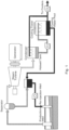
- FIG. 1 A general schematic of one kind geothermal plant is shown in Figure 1 .
- a production well provides mineralized water - in the form of steam or a combination of heated water and steam - that is led through a production line to a separator.
- the separator In the separator the pressure is reduced, causing the super-heated water from the underground pressurized foundation to become steam.
- the steam is led off to turn a steam turbine, while water from the separator and from downstream cooing tanks and condensers is recovered and led through the reinjection lines to the reinjection well.
- the water in the reinjection lines contains minerals derived from the underground formation and is responsible for the build-up of scale on the walls of the conduits in the plant. It is observed that scale builds up the most in the production line and in the reinjection line.
- Another geothermal plant is called a binary geothermal plant.
- hot water is extracted with a production well and is delivered via a production well line to a heat exchanger, where the heat of the water is used to vaporize a fluid that turns a turbine to generate electricity.
- the vapor returns through a condenser to the heat exchanger, and cooled water is injected back into the formation by a reinjection well that includes a reinjection well line.
- the geothermal plants have production well lines and reinjection well lines that tend to build up the scales described herein. Those scales can be removed or mitigated using the methods herein.
- a geothermal plant having a production well, a production well line leading form the well to a separator, a steam turbine running off steam from the separator, a re-injection well, and a return line for water from the separator to the re-injection well.
- the plant has one or more injectors disposed in the return line, in the production well line, or in both. These injectors are configured to deliver an acid composition and a caustic composition into the return line, into the production well line, or into both from a reservoir or from reservoirs coupled to the one or more injectors.
- the one or more injectors are configured to deliver alternately the acid composition and the caustic composition into the conduits of the geothermal plant.
- the caustic composition and the acid composition are injected into conduits of the geothermal plant upstream of scale deposits, so that the deposits are exposed alternately to acid and to caustic.
- the two treatments together act to dissolve both the silica and alumina contents of the scale.
- Laboratory dissolution tests can be performed to determine the required mix of the chemicals and the most effective timing of oscillating the above acid and caustic washes and rinses for a specific geothermal plant.
- the chemicals i.e. the respective acid and caustic compositions
- a lance large quill
- Flows of the calculated chemicals are injected in a series of patterns and intervals as determined by the laboratory analyses and experience.
- Treatment variables include the pH to which the flowing water in the conduit is exposed during a wash cycle, the timing of any rinse cycle between acid and caustic treatments, the length of the individual treatment or wash cycle, and the total number of cycles carried out, all of which can be optimized to remove scale (or prevent its formation) most efficiently.
- the treatments are carried out under full working conditions, that is to say under working pressure and temperature. This means it is not necessary to halt production of the well or to interrupt the process in any way to control scale build-up.
- caustic has been used to try and dissolve geothermal silica-based deposits before but with varying success.
- This method uses chelators and surfactants to enhance that part of the process. Chelators and surfactants are used to reduce the negative impacts cations in the deposits have on dissolution rates and also the re-deposition of the dissolved scales.
- the process also uses an acid step to attack and dissolve deposit components that are not caustic soluble to increase the porosity and surface area of the caustic soluble silica-based deposits.
- the cleaning process is done under full working conditions; i.e., under working pressure and temperature, without any halt in production or tear down of the plant.
- Deposit sample from a geothermal plant in New Zealand was isolated and sieved through a 10 mesh sieve. The fraction passing through the sieve was utilized in the studies. Elemental analysis of the deposit samples indicated that they comprised 66.6-68.3 wt% silicon (as SiO 2 ) and 10.8-11.2 wt% aluminum (as Al 2 O 3 ). Loss on ignition (1000 °C) was 6.8-11.3 wt%.
- Synthetic brine recipe used in the studies was as follows. Alkalinity, Total (as CaCO 3 ) 40.9 ppm Chloride (as Cl) 2016.0 ppm Sulfate (as SO 4 ) 45.3 ppm Calcium, Total (as CaCO 3 ) 43.4 ppm Silicon, Soluble (as SiO 2 ) 464.7 ppm Sodium, Soluble (as Na) 1285.0 ppm Phosphorous, Total (as PO4 ) 3.1 ppm pH 7.1
- the alkaline caustic cleaner in this testing had the following composition. 50 wt% NaOH 50% 38 wt% EDTA.Na4 24% Dowfax C6L 1% Water 25% 1g of #10 mesh sieved scale was charged to a 100 ml solution of alkaline caustic cleaner diluted to 0.25 wt% NaOH in synthetic brine solution. The solution was held for 6 hours at 90 °C during which time aliquots were collected for analysis. After which the solution was filtered and the isolated precipitate was then charged to 100 ml DI water and held at 90 °C for 5 minutes. The solution was then filtered and the isolated sample was dried at 105 °C for weight loss.
- a blank was conducted in the same fashion utilizing synthetic brine solution absent the addition of the alkaline caustic cleaner.
- the silicon content of the isolated sample solutions was determined by Hach silicomolybdate Method 8185.
- the aluminum content was determined by utilizing Hach TNT 848 vials, Method 10215 TNT Plus.
- the silicon content was analyzed and found to be 230 ppm (as SiO 2 ) after 1-hour, and gradually increased to 302 ppm after 6-hours.
- the blank solution silicon content was analyzed and found to be ⁇ 50 ppm for the duration of the 6-hour hold period.
- the aluminum content was analyzed and found to be 0.4 ppm (as Al) after 1-hour, and increased to 1.1 ppm after 6-hours.
- the blank solution aluminum content was analyzed and found to be essentially zero for the duration of the 6-hour hold period.
- the alkaline caustic cleaner in this testing was comprised the following composition. 50 wt% NaOH 50.00% 38 wt% EDTA.Na4 26.3% Water 25.00%
- the test was conducted as in Comparative Example 1 except the scale was treated with a 1 wt % solution of either sulfuric acid or hydrochloric acid diluted in synthetic brine prior to treatment with the alkaline caustic cleaner diluted to 0.25 wt% NaOH in synthetic brine solution.
- the sequence for the treatment was as follows:
- the benefit of the acid pre-treatment step was also observed in the weight loss analysis of the isolated scale sample.
- the measured weight loss was 2.6 wt%, 4.2 wt%, and 4.5 wt% for the blank, sulfuric acid pre-treatment, and hydrochloric acid pretreatment; respectively. This equates to a relative increase in weight loss versus the blank of 62% - 73%.
- These dissolution values are significantly greater than the weight loss of 1.9 wt% (12% relative to the blank) observed for the alkaline caustic cleaner alone treatment in Comparative Example I.
Landscapes
- Engineering & Computer Science (AREA)
- Chemical & Material Sciences (AREA)
- Life Sciences & Earth Sciences (AREA)
- Combustion & Propulsion (AREA)
- Chemical Kinetics & Catalysis (AREA)
- Environmental & Geological Engineering (AREA)
- General Chemical & Material Sciences (AREA)
- Organic Chemistry (AREA)
- Mining & Mineral Resources (AREA)
- Geology (AREA)
- Mechanical Engineering (AREA)
- Water Supply & Treatment (AREA)
- General Life Sciences & Earth Sciences (AREA)
- General Engineering & Computer Science (AREA)
- Hydrology & Water Resources (AREA)
- Sustainable Energy (AREA)
- Physics & Mathematics (AREA)
- Fluid Mechanics (AREA)
- Geochemistry & Mineralogy (AREA)
- Inorganic Chemistry (AREA)
- Materials Engineering (AREA)
- Metallurgy (AREA)
- Cleaning And De-Greasing Of Metallic Materials By Chemical Methods (AREA)
- Removal Of Specific Substances (AREA)
- Detergent Compositions (AREA)
- Cleaning By Liquid Or Steam (AREA)
- Solid-Sorbent Or Filter-Aiding Compositions (AREA)
- Agricultural Chemicals And Associated Chemicals (AREA)
- Cleaning In General (AREA)
- Preventing Corrosion Or Incrustation Of Metals (AREA)
Description
- In the operation of a geothermal plant constituents in the steam undergo cycling and/or temperature changes which result in the supersaturation of various species and deposit formation. For example, the production well and re-injection lines are known to be areas in the process in which precipitate formation is observed. Deposits in these lines can extend from centimeters to meters from the well casing. The deposits can lead to decreased plant efficiency. As an example, silica-based mineral accumulations are typical of the deposits found in the re-injection lines. The accumulation reduces flow rates in the re-injection, ultimately necessitating throttling back the flow from the production well and resulting in decreased energy production from the plant. Maintaining the system free of deposits to attain maximum efficiency is a major cost to geothermal plant operators.
- Another challenge is maximizing well reservoir productivity over time. Various techniques both mechanical and chemical have been described to stimulate or maintain the steam output; these include hydraulic fracturing (or fracking), matrix acidization, and chelant treatment.
- Conventional solutions for maintaining the re-injection lines clean and/or stimulating the well reservoir include mechanical means including the use of drilling rigs, hammer tools and machining bits that are lowered into the well. Others include pumping HF or mud acid (HCl and HF) down the well. This requires the well to be taken off line and is a very dangerous process because of the severity of HF. And fracking involves using explosives or high-pressure water. These can stimulate the ability of the formation to receive fluids but require the well to be taken out of service.
-
Earhart et al. US Pat. No. 4713119 described a process for removing specifically alkali metal alumina silicate scale deposits from the surface of chemical process equipment by an alternating wash of acid and base. But the Earhart process provides for direct contact of the scale with acid and base wash and drainage from the scale between washes. And it still requires the process equipment to be shut down while the treatment is going on.US2015210567 andJP2013212457 WO03092919 US2014083919 relates to a method of recovering solids from water-based effluents. There is a continuing need for processes that maintain equipment like a geothermal plant free of scale without losing valuable production time and output. - A method of removing built up scale in a conduit of a geothermal plant is defined in claim 1. Typically, the built-up scale comprises a predominantly amorphous silica based scale, an alkali metal aluminosilicate-based scale, or an alkaline earth metal aluminosilicate-based scale, and the acid composition and the caustic composition do not come into direct contact with the scale but are diluted by the fluid flowing in the conduit. In various embodiments, the fluid is first treated with the acid composition and in others, the fluid is first treated with the caustic composition. The acid and caustic compositions can be continuously fed or can be added in batches during the respective treating steps. The caustic composition contains 1-40 wt.% alkali, 0.5-30 wt.% chelator and 0.0-20 wt.% surfactant.
- The method comprises alternately injecting the acid composition and the caustic composition into a location such as into the production well line of the plant or into the re-injection line of the plant, wherein the injecting steps are carried out without halting operation of the geothermal plant.
- The built-up scale comprises an aluminosilicate scale, such as an alkali metal aluminosilicate or an alkaline earth metal aluminosilicate-based scale. The acid composition and the caustic composition do not come into direct contact with the scale but are diluted by the fluid flowing in the conduit.
- A non-limiting example of a geothermal plant for use in the process comprises a production well, a production well line leading from the well to a separator, a steam turbine running off steam from the separator, a re-injection well, and a return line for water from the separator to the re-injection well, and further comprising one or more injectors disposed in the return line, in the production well line, or in both, wherein the one or more injectors are configured to deliver an acid composition and a caustic composition into the return line, into the production well line, or into both from a reservoir or from reservoirs coupled to the one or more injectors.
- A major differentiator of this technology is that the treatment process can be practiced on-line; i.e., the well to be treated does not have to be taken out of service. Additionally, the treatments can be alternatively added to a continuous flow of the re-injected process water; i.e., the wash solutions are not required to stand in contact with the deposit for the treatment to be effective.
- The following detailed description is merely exemplary in nature and is not intended to limit the present disclosure or the application and uses thereof. Furthermore, there is no intention to be bound by any theory presented in the preceding background or the following detailed description.
- An acid composition as used herein is an aqueous solution having a sufficiently low pH that injecting the acid composition into a conduit having flowing mineralized water lowers the pH of the flowing water to a pH below 7, creating a suitable condition for partially dissolving an aluminosilicate-based scale formed on the inner walls of the conduit. Lowering the pH of the flowing water in the conduit is affected also by the amount of acid composition provided in the conduit during a treatment step, and by the rate at which it is added, compared to the rate at which the flowing water is flowing.
- So the acid treatment provides an environment with a low pH in the conduit, such as below pH 7. In various embodiments, the pH is adjusted by the acid treatment to be less than 6, less than 5, less than 4, less than 3, less than 2, or less than 1. Alternatively, the effect of the acid treatment can be observed in that it lowers the pH of the flowing water in the conduit by at least 1 unit, by at least 2 units, by at least 3 units, by at least 4 units, by at least 5 units, or by at least 6 units.
- The acids suitable for use in the treatment include, without limitation, sulfuric acid, hydrochloric acid, nitric acid, acetic acid, formic acid, and sulfamic acid. In various embodiments, sulfuric acid and hydrochloric acid are used. Mixtures of acids can also be used. In an embodiment, the more hazardous hydrofluoric acid utilized in prior art applications is not used. Suitable concentrations of acid range from about 0.1 M to about 6 M.
- A Caustic composition suitable for use in caustic treatment of a pipe or conduit contains an alkali and also contains a chelator. A surfactant is an optional component of the caustic composition. The caustic composition can be formulated as a single drum product or the components can be co-fed simultaneously to the system.
- A caustic composition as used herein is an aqueous solution having a sufficiently high pH that injecting the caustic composition into a conduit having flowing water raises the pH of the flowing water to a pH above 7, creating a suitable condition for partially dissolving an aluminosilicate-based scale formed on the inner walls of the conduit. The extent to which the pH of the flowing water in the conduit is raised by the caustic treatment is affected also by the amount of caustic composition provided in the conduit during a treatment step, and by the rate at which it is added, compared to the rate at which the mineralized water is flowing.
- The caustic treatment provides an environment with a high pH in the conduit, such as above 7. In various embodiments, the pH is adjusted by the caustic treatment to more than 8, more than 9, more than 10, more than 11, more than 12, or more than 13. Alternatively, the effect of the caustic treatment can be observed in that it raises the pH of the flowing water in the conduit by at least 1 unit, by at least 2 units, by at least 3 units, by at least 4 units, by at least 5 units, or by at least 6 units.
- Non-limiting examples of the alkali include sodium hydroxide, potassium hydroxide, and sodium carbonate. A strong base such as the alkali metal hydroxide is preferred. In non-limiting fashion, the alkali is provided as a solution with a concentration of about 0.1 M to about 6 M.
- The chelator functions by solubilizing predominantly calcium or magnesium ions, preventing their precipitation, which would interfere with the caustic treatment of the aluminosilicate scale in the conduit. The chelator component of the caustic composition contains functional groups that can form stable complexes with divalent ions like Ca2+ and Mg2+ and keep them out of solution. A wide range of functional groups can chelate calcium and magnesium in this way. Commonly used chelators include those having a plurality of carboxyl groups and those having a plurality of phosphonic acid groups. At the basic pH of the caustic composition, the carboxyls and phosphonic acid groups are present in salt form (carboxylate and phosphonate, respectively), the counterion corresponding to the alkali metal present in the alkali. That counterion is usually Na+ or K+.
- Non-limiting examples of chelators include the following free acids as well as their sodium and potassium salts: 1) organic acids such as gluconic acid and citric acid; 2) amino methylenecarboxylic acid derivatives such as ethylenediaminetetracetic acid (EDTA), diethylenetriaminepentaacetic acid (DTPA), and N-(2-hydroxyethyl)ethylenediaminetriacetic acid (HEDTA); other polycarboxylates such as Glutamic acid, N,N-diacetic acid (GLDA) and nitrilotriacetic acid (NTA); amino methylenephosphonic acid derivatives such as aminotris(methylenephosphonic acid) (ATMP), diethylenetriamine penta(methylene phosphonic acid) (DTPMPA), and bis(hexamethylenetriamine) penta(methylenephosphonic acid) (BHTPMP). Gluconic acid is preferred in some embodiments.
- In various embodiments, in addition to the acid and caustic treatments described herein, the scale can be conditioned before those treatments by dosing with chelator for a period of time sufficient to render the scale amenable to removal by the subsequent acid and caustic treatments.
- Preferably the surfactant component is a low-foaming surfactant that maintains performance in an alkaline environment. The surfactant component of the caustic cleaner, when utilized, can be selected from non-ionic surfactants, amphoteric surfactants, and anionic surfactants, as well as their mixtures and their blends with non-ionic surfactants. Alkyl diphenyloxide disulfonates are one example of a suitable anionic surfactant, while amphoteric surfactants are exemplified by alkylether hydroxypropyl sultaines. The latter are described more fully in Nadolsky,
U.S. Pat. No. 4,891 159 . - Exemplary non-ionic surfactants in such blends include linear or branched alcohol alkoxylates.
- Weight ranges for the alkali, chelator, and optional surfactant blend of the caustic composition are given in the table.
wt % Most Preferred, wt.% Alkali 1.0 - 40.0 2.0 - 30.0 Chelant 0.5-30.0 1.0 - 20.0 Surfactant 0.0-20.0 0.5-10.0 - Analysis of scale from a typical geothermal plant reveals the scale contains major amounts of silica (as SiO2) and alumina (as Al2O3), with silica higher than alumina. While the invention is not limited by theory or mode of action, it is observed that the treatment with the acid composition (the "acid wash") tends to dissolve out the alumina component of the scale, which raises the amount of aluminum detected in the fluid running through the conduit. And the "caustic wash" tends to dissolve out the silica component of the scale, causing a higher level of silicon to be observed in the fluid during a caustic treatment step. In this way, alternating acid and caustic treatments tends to dissolve and eliminate the scale formed in various parts of the geothermal plant, such as the production lines and the reinjection lines. This phenomenon is further illustrated in the Examples.
- A general schematic of one kind geothermal plant is shown in
Figure 1 . There a production well provides mineralized water - in the form of steam or a combination of heated water and steam - that is led through a production line to a separator. In the separator the pressure is reduced, causing the super-heated water from the underground pressurized foundation to become steam. The steam is led off to turn a steam turbine, while water from the separator and from downstream cooing tanks and condensers is recovered and led through the reinjection lines to the reinjection well. The water in the reinjection lines contains minerals derived from the underground formation and is responsible for the build-up of scale on the walls of the conduits in the plant. It is observed that scale builds up the most in the production line and in the reinjection line. - Another geothermal plant is called a binary geothermal plant. Here, hot water is extracted with a production well and is delivered via a production well line to a heat exchanger, where the heat of the water is used to vaporize a fluid that turns a turbine to generate electricity. The vapor returns through a condenser to the heat exchanger, and cooled water is injected back into the formation by a reinjection well that includes a reinjection well line. In various embodiments the geothermal plants have production well lines and reinjection well lines that tend to build up the scales described herein. Those scales can be removed or mitigated using the methods herein.
- In one non-limiting embodiment, a geothermal plant is thus provided having a production well, a production well line leading form the well to a separator, a steam turbine running off steam from the separator, a re-injection well, and a return line for water from the separator to the re-injection well. For carrying out the cleaning process, the plant has one or more injectors disposed in the return line, in the production well line, or in both. These injectors are configured to deliver an acid composition and a caustic composition into the return line, into the production well line, or into both from a reservoir or from reservoirs coupled to the one or more injectors. The one or more injectors are configured to deliver alternately the acid composition and the caustic composition into the conduits of the geothermal plant.
- The caustic composition and the acid composition are injected into conduits of the geothermal plant upstream of scale deposits, so that the deposits are exposed alternately to acid and to caustic. The two treatments together act to dissolve both the silica and alumina contents of the scale.
- Laboratory dissolution tests can be performed to determine the required mix of the chemicals and the most effective timing of oscillating the above acid and caustic washes and rinses for a specific geothermal plant. In a non-limiting embodiment, the chemicals (i.e. the respective acid and caustic compositions) are injected through a lance (large quill) into the main flow of the geothermal re-injection well, usually through the top of the well head above the crown head valve. Flows of the calculated chemicals are injected in a series of patterns and intervals as determined by the laboratory analyses and experience. Treatment variables include the pH to which the flowing water in the conduit is exposed during a wash cycle, the timing of any rinse cycle between acid and caustic treatments, the length of the individual treatment or wash cycle, and the total number of cycles carried out, all of which can be optimized to remove scale (or prevent its formation) most efficiently. Advantageously, the treatments are carried out under full working conditions, that is to say under working pressure and temperature. This means it is not necessary to halt production of the well or to interrupt the process in any way to control scale build-up.
- To sum up, caustic has been used to try and dissolve geothermal silica-based deposits before but with varying success. This method uses chelators and surfactants to enhance that part of the process. Chelators and surfactants are used to reduce the negative impacts cations in the deposits have on dissolution rates and also the re-deposition of the dissolved scales. The process also uses an acid step to attack and dissolve deposit components that are not caustic soluble to increase the porosity and surface area of the caustic soluble silica-based deposits. Finally, the cleaning process is done under full working conditions; i.e., under working pressure and temperature, without any halt in production or tear down of the plant.
- Deposit sample from a geothermal plant in New Zealand was isolated and sieved through a 10 mesh sieve. The fraction passing through the sieve was utilized in the studies. Elemental analysis of the deposit samples indicated that they comprised 66.6-68.3 wt% silicon (as SiO2) and 10.8-11.2 wt% aluminum (as Al2O3). Loss on ignition (1000 °C) was 6.8-11.3 wt%.
- Synthetic brine recipe used in the studies was as follows.
Alkalinity, Total (as CaCO3) 40.9 ppm Chloride (as Cl) 2016.0 ppm Sulfate (as SO4) 45.3 ppm Calcium, Total (as CaCO3) 43.4 ppm Silicon, Soluble (as SiO2) 464.7 ppm Sodium, Soluble (as Na) 1285.0 ppm Phosphorous, Total (as PO4) 3.1 ppm pH 7.1 - The alkaline caustic cleaner in this testing had the following composition.
50 wt% NaOH 50% 38 wt% EDTA.Na4 24% Dowfax C6L 1% Water 25% - A blank was conducted in the same fashion utilizing synthetic brine solution absent the addition of the alkaline caustic cleaner.
- The silicon content of the isolated sample solutions was determined by Hach silicomolybdate Method 8185. The aluminum content was determined by utilizing Hach TNT 848 vials, Method 10215 TNT Plus.
- For the alkaline caustic cleaner experiment the silicon content was analyzed and found to be 230 ppm (as SiO2) after 1-hour, and gradually increased to 302 ppm after 6-hours. The blank solution silicon content was analyzed and found to be ~50 ppm for the duration of the 6-hour hold period.
- For the alkaline caustic cleaner experiment the aluminum content was analyzed and found to be 0.4 ppm (as Al) after 1-hour, and increased to 1.1 ppm after 6-hours. The blank solution aluminum content was analyzed and found to be essentially zero for the duration of the 6-hour hold period.
- At the end of the experiment the weight loss of the isolated scale sample for the alkaline caustic cleaner experiment was 1.9 wt% compared to 1.7 wt% for the blank.
- The alkaline caustic cleaner in this testing was comprised the following composition.
50 wt% NaOH 50.00% 38 wt% EDTA.Na4 26.3% Water 25.00% - The test was conducted as in Comparative Example 1 except the scale was treated with a 1 wt % solution of either sulfuric acid or hydrochloric acid diluted in synthetic brine prior to treatment with the alkaline caustic cleaner diluted to 0.25 wt% NaOH in synthetic brine solution. The sequence for the treatment was as follows:
- 1) Treat with 100 ml acid solution for 1-hour @ 90 °C.
- 2) Filter the solution and isolate the undissolved scale fragments.
- 3) Treat the precipitate with 100 ml DI water for 5-minutes @ 90 °C.
- 4) Filter the solution and isolate the undissolved scale fragments.
- 5) Treat the precipitate with alkaline caustic cleaner for 1-hour @ 90 °C.
- 6) Filter the solution and isolate the undissolved scale fragments.
- 7) Treat the precipitate with 100 ml DI water for 5-minutes @ 90 °C.
- 8) Filter the solution and isolate the undissolved scale fragments.
- 9) Repeat steps 1-8 two additional times reusing the same treatment solutions except the DI water rinse was changed out after every treatment.
- A blank was also conducted in the same fashion as Comparative Example I using synthetic brine solution absent the addition of acid and alkaline caustic cleaner. The isolate solution samples were analyzed for silicon content as described in Comparative Example I, the results of which are summarized in Table 1.
Table 1 Silicon as ppm SiO2 Solutions Blank H2SO4 HCl Acid Cycle 1 375 147 145 Caustic Cleaner Cycle 1 363 699 717 Acid Cycle 2 325 137 146 Caustic Cleaner Cycle 2 332 757 797 Acid Cycle 3 312 142 140 Caustic Cleaner Cycle 3 176 768 782 - Based on this study it can be observed in Table 1 that the silicon content of alkaline caustic cleaner solution was ~700 ppm after 1st cycle and increased upwards of ~800 ppm after the 3rd cycle. This result was essentially the same for pretreatments with either sulfuric (H2SO4) or hydrochloric (HCl) acids. It is further noted that the silicon content in the alkaline caustic cleaner solution even after the 1st cycle was significantly increased compared to the alkaline caustic cleaner alone treatment in Comparative Example I; e.g., ~700 v ~300 ppm, respectively.
- The benefit of the acid pre-treatment step was also observed in the weight loss analysis of the isolated scale sample. In this testing the measured weight loss was 2.6 wt%, 4.2 wt%, and 4.5 wt% for the blank, sulfuric acid pre-treatment, and hydrochloric acid pretreatment; respectively. This equates to a relative increase in weight loss versus the blank of 62% - 73%. These dissolution values are significantly greater than the weight loss of 1.9 wt% (12% relative to the blank) observed for the alkaline caustic cleaner alone treatment in Comparative Example I.
- Repeat of the sulfuric acid pretreatment experiment of Example I with the following modifications.
- 1) Fresh sulfuric acid and alkaline caustic cleaner solutions were utilized in each cycle.
- 2) The treatments with the sulfuric acid solutions were shortened to 15-minutes at 90 °C.
- 3) The treatments with the DI water treatments were shortened to 2-minutes at 90 °C.
- 4) The treatments with the alkaline caustic cleaner solutions were shortened to 15-minutes at 90 °C.
- Using fresh sulfuric acid and alkaline caustic cleaner solutions in each cycle was a better model of multiple treatments of the injection well over time.
- A blank was also conducted in the same fashion as Comparative Example I utilizing synthetic brine solution absent the addition of acid and alkaline caustic cleaner. The isolate solution samples were analyzed for silicon and aluminum content as described in Comparative Example I, the results of which are summarized in Table 2. In this example the aluminum concentration in the samples was measured by ICP analysis.
Table 2 Silicon as ppm SiO2 Aluminum as ppm Al Solutions Blank H2SO4 Blank H2SO4 Acid Cycle 1 36 150 1 21 Caustic Cleaner Cycle 1 14 695 1 4 Acid Cycle 2 56 133 1 6 Caustic Cleaner Cycle 2 2 725 1 5 Acid Cycle 3 13 122 1 5 Caustic Cleaner Cycle 3 7 763 1 5 - Based on this study it can be seen in Table 2 that the benefit of pretreating the deposit with acid prior to treatment with the alkaline caustic cleaner resulted as was observed in Example II. It can also be seen that the acid treatment was more effective in dissolving the aluminum containing portion of the deposit, especially after the 1st cycle.
- Given that the subsequent alkaline caustic cleaner treatments in this example yield a greater volume of silicon containing diluent (3 x 100 ml @ ~700 ppm each) versus Example II in which the alkaline caustic cleaner solution was recycled (100 ml total @ ~750 ppm) it was hypothesized that the weight loss of the scale would be greater. This was supported by a measured weight loss of 6.2 wt % for the treated sample versus 1.9 wt% for the blank. This equates to a relative increase in weight loss versus the blank of 226%.
- The following describes the general approach of the process of Online Well Cleaning.
- 1. Water and scale analysis. Each well has different water chemistry, temperatures and therefore unique scaling elements. Step one is to analyze the water and scale.
- 2. Once the chemical and temperature profiles are established, calculations are done to determine dose rates to achieve pH levels of the continuous flow of the well. The target pHs vary due to the type of scale but are typically 1.5 to 2.5 in acid conditions and 11 to 12 for alkaline conditions.
- 3. Scale samples are also tested in the lab to determine what chelants and dissolution chemistries are needed to dissolve the scales. Bench analyses are performed. Chelants may include but are not limited to: NTA, DPTA, EDTA, GDLA, and combinations thereof.
- 4. In a typical example, the starting flow was 64 tons/hr and as silicates were determined to be an issue the chelant composition GeoSol® GS1824 was dosed for 15min at 30 L/hr to precondition the scale.
- 5. The acid composition GeoSol® 1001 was then added at 0.5% for 20 min to remove the targeted silicates. After addition of the acid composition it was flushed from the system with 200 tons of brine before the next step.
- 6. The chelant composition GeoSol® GS1824 was restarted and dosed for 45 minutes at 15 L/hr. This is to shift the aluminum laden silica scales. After the first cycle of treatment, a back pressure drop of 7.2 bar to 5.2 bar was observed and a flow increase from 64t/hr to 180 t/hr.
- 7. After 300 minutes the well was flushed with 300 tons of brine to remove the hydrophobic surface elements on the scale and the process repeated the following day.
- 8. Upon completion of treatment the flow had increased to 2001/hr ( from a starting flow of 64t/hr) and back pressure dropped from 7.2 bar to 5.9 bar.
- In short the process relies on:
- 1. Predetermination of what will dissolve the scale and is correlated with the brine chemistry and temperature (to prevent secondary precipitation reactions).
- 2. As this is often a two-step process using chelants, dispersants, acid, and alkali phases, optional intermediate steps may be needed to flush away hydrophobic secondary formations on the scale that hinder the reaction efficiency. In these phases, dispersants can be injected into the brine flow to assist flushing.
- While at least one exemplary embodiment has been presented in the foregoing detailed description, it should be appreciated that a vast number of variations exist. It should also be appreciated that the exemplary embodiment or exemplary embodiments are only examples, and are not intended to limit the scope, applicability, or configuration of the present disclosure in any way. Rather, the foregoing detailed description will provide those skilled in the art with a convenient road map for implementing an exemplary embodiment of the present disclosure. It being understood that various changes may be made in the function and arrangement of elements described in an exemplary embodiment without departing from the scope of the present disclosure as set forth in the appended claims.
Claims (7)
- Method of removing built up scale in a conduit of a geothermal plant, in which conduit a fluid comprising mineralized water is flowing and in which conduit the built up scale to be removed comprises an aluminosilicate scale, the method comprising treating the fluid in the conduit by alternately injecting into the conduit upstream of the location where it is desired to remove the scale an acid composition and a caustic composition, wherein treating is carried out without stopping the fluid flow in the conduit, and wherein the caustic composition comprises 1-40 wt.% alkali, 0.5-30 wt.% chelator, and 0.0-20 wt.% surfactant.
- The method according to claim 1, wherein the built-up scale comprises an alkali metal aluminosilicate or an alkaline earth metal aluminosilicate-based scale, and wherein the acid composition and the caustic composition do not come into direct contact with the scale but are diluted by the fluid flowing in the conduit.
- The method according to claims 1 or 2, wherein the fluid is first treated with the acid composition.
- The method according to claims 1 or 2, wherein the fluid is first treated with the caustic composition.
- The method according to any preceding claim, comprising continuously feeding the acid composition and the caustic composition into the conduit during the treating step.
- The method according to any of claims 1 to 4, comprising batch addition of the acid composition and the caustic composition into the conduit during the treating step.
- The method according to claim 1, wherein alternately treating the fluid in the conduit comprises injecting the acid composition and the caustic composition into a production well line of the plant or into a re-injection line of the plant, wherein the injecting steps are carried out without halting operation of the geothermal plant.
Priority Applications (2)
| Application Number | Priority Date | Filing Date | Title |
|---|---|---|---|
| EP24196644.9A EP4461922A3 (en) | 2020-01-21 | 2021-01-21 | Geothermal well stimulation and silica based deposit removal |
| HRP20250005TT HRP20250005T1 (en) | 2020-01-21 | 2021-01-21 | Geothermal well stimulation and silica based deposit removal |
Applications Claiming Priority (2)
| Application Number | Priority Date | Filing Date | Title |
|---|---|---|---|
| US16/747,604 US11821287B2 (en) | 2020-01-21 | 2020-01-21 | Geothermal well stimulation and silca based deposit removal |
| PCT/US2021/014280 WO2021150657A1 (en) | 2020-01-21 | 2021-01-21 | Geothermal well stimulation and silica based deposit removal |
Related Child Applications (2)
| Application Number | Title | Priority Date | Filing Date |
|---|---|---|---|
| EP24196644.9A Division-Into EP4461922A3 (en) | 2020-01-21 | 2021-01-21 | Geothermal well stimulation and silica based deposit removal |
| EP24196644.9A Division EP4461922A3 (en) | 2020-01-21 | 2021-01-21 | Geothermal well stimulation and silica based deposit removal |
Publications (3)
| Publication Number | Publication Date |
|---|---|
| EP4093708A1 EP4093708A1 (en) | 2022-11-30 |
| EP4093708A4 EP4093708A4 (en) | 2023-08-02 |
| EP4093708B1 true EP4093708B1 (en) | 2024-10-09 |
Family
ID=76857943
Family Applications (2)
| Application Number | Title | Priority Date | Filing Date |
|---|---|---|---|
| EP24196644.9A Pending EP4461922A3 (en) | 2020-01-21 | 2021-01-21 | Geothermal well stimulation and silica based deposit removal |
| EP21744172.4A Active EP4093708B1 (en) | 2020-01-21 | 2021-01-21 | Geothermal well stimulation and silica based deposit removal |
Family Applications Before (1)
| Application Number | Title | Priority Date | Filing Date |
|---|---|---|---|
| EP24196644.9A Pending EP4461922A3 (en) | 2020-01-21 | 2021-01-21 | Geothermal well stimulation and silica based deposit removal |
Country Status (9)
| Country | Link |
|---|---|
| US (2) | US11821287B2 (en) |
| EP (2) | EP4461922A3 (en) |
| JP (1) | JP2023513422A (en) |
| CL (1) | CL2022001968A1 (en) |
| HR (1) | HRP20250005T1 (en) |
| MX (1) | MX2022008851A (en) |
| PH (1) | PH12022551846A1 (en) |
| PT (1) | PT4093708T (en) |
| WO (1) | WO2021150657A1 (en) |
Families Citing this family (5)
| Publication number | Priority date | Publication date | Assignee | Title |
|---|---|---|---|---|
| JP7094047B1 (en) * | 2021-02-24 | 2022-07-01 | 日本重化学工業株式会社 | Geothermal turbine blade scale removal method and geothermal power generation method |
| CN114412416B (en) * | 2022-03-09 | 2025-06-27 | 山东省鲁南地质工程勘察院(山东省地质矿产勘查开发局第二地质大队) | A geothermal heat reservoir and transmission pipeline non-pump descaling device and use method |
| WO2024171837A1 (en) * | 2023-02-16 | 2024-08-22 | 富士電機株式会社 | Method for removing scale in geothermal power plant |
| CN121181148A (en) * | 2024-06-20 | 2025-12-23 | 埃科莱布美国股份有限公司 | Compositions and methods for treating scale |
| CN119430353A (en) * | 2024-11-26 | 2025-02-14 | 国家能源集团宁夏煤业有限责任公司 | Method for increasing the operating load of evaporator system in high-silicon salt water |
Family Cites Families (24)
| Publication number | Priority date | Publication date | Assignee | Title |
|---|---|---|---|---|
| US4500434A (en) | 1982-12-02 | 1985-02-19 | Union Oil Company Of California | Inhibiting scale precipitation from high temperature brine |
| US4713119A (en) | 1986-03-20 | 1987-12-15 | Stauffer Chemical Company | Process for removing alkali metal aluminum silicate scale deposits from surfaces of chemical process equipment |
| US4692252A (en) * | 1986-03-24 | 1987-09-08 | Vertech Treatment Systems, Inc. | Method of removing scale from wet oxidation treatment apparatus |
| US4891159A (en) | 1986-08-27 | 1990-01-02 | Miranol Inc. | Low-foam alkali-stable amphoteric surface active agents |
| JPH0814329B2 (en) * | 1986-09-18 | 1996-02-14 | 株式会社キッツ | Structure of valve seat |
| US4744908A (en) * | 1987-02-24 | 1988-05-17 | Vertech Treatment Systems, Inc. | Process for effecting chemical reactions |
| US5474097A (en) * | 1993-11-10 | 1995-12-12 | Atlantic Richfield Company | Scale removal and disposal system and method |
| US5665242A (en) * | 1995-08-25 | 1997-09-09 | Union Oil Company Of California | Inhibition of silica precipitation |
| ID17651A (en) | 1996-07-15 | 1998-01-15 | Union Oil Co | OBLIGATORS FORMING SILICATED SCALE |
| AU1943199A (en) | 1998-01-30 | 1999-08-16 | Rhodia Inc. | Low foaming surfactant compositions useful in highly alkaline caustic cleaners |
| AU2003223762B2 (en) | 2002-04-30 | 2008-12-04 | Nalco Company | Methods of simultaneously cleaning and disinfecting industrial water systems |
| US20070029252A1 (en) * | 2005-04-12 | 2007-02-08 | Dunson James B Jr | System and process for biomass treatment |
| JP4766703B2 (en) | 2008-02-27 | 2011-09-07 | 日本電信電話株式会社 | Edge node and bandwidth control method |
| US8584757B2 (en) * | 2010-04-21 | 2013-11-19 | Halliburton Energy Services, Inc. | Method and composition for treating fluids before injection into subterranean zones |
| US9976070B2 (en) * | 2010-07-19 | 2018-05-22 | Baker Hughes, A Ge Company, Llc | Method of using shaped compressed pellets in well treatment operations |
| US10822536B2 (en) | 2010-07-19 | 2020-11-03 | Baker Hughes, A Ge Company, Llc | Method of using a screen containing a composite for release of well treatment agent into a well |
| US20120217012A1 (en) * | 2011-02-24 | 2012-08-30 | John Gregory Darby | Method of introducing treatment agents into a well or flow conduit |
| PH12013502042B1 (en) * | 2011-04-19 | 2017-11-17 | Fuji Electric Co Ltd | Scale inhibition method and geothermal power generating device |
| JP2013021245A (en) * | 2011-07-14 | 2013-01-31 | Renesas Electronics Corp | Inductor |
| JP2013212457A (en) | 2012-04-02 | 2013-10-17 | Fuji Electric Co Ltd | Scale preventing apparatus, and geothermal power generation system using the apparatus, and scale preventing method |
| JP5906926B2 (en) | 2012-04-27 | 2016-04-20 | 富士電機株式会社 | Scale suppression device, geothermal power generation system using the device, and scale suppression method |
| CA2827933C (en) | 2012-09-25 | 2018-09-18 | Xiaomei Li | Method and apparatus for recovering solids from water-based effluent |
| EP3132112A4 (en) | 2014-04-14 | 2017-10-04 | Flex-chem Holding Company LLC | Stimulation of wells in nano-darcy shale formations |
| US20160243597A1 (en) * | 2015-02-24 | 2016-08-25 | PSI Pressure Systems Corp. | Magnetic mount for blasting equipment and related methods |
-
2020
- 2020-01-21 US US16/747,604 patent/US11821287B2/en active Active
-
2021
- 2021-01-21 JP JP2022544160A patent/JP2023513422A/en active Pending
- 2021-01-21 EP EP24196644.9A patent/EP4461922A3/en active Pending
- 2021-01-21 WO PCT/US2021/014280 patent/WO2021150657A1/en not_active Ceased
- 2021-01-21 MX MX2022008851A patent/MX2022008851A/en unknown
- 2021-01-21 EP EP21744172.4A patent/EP4093708B1/en active Active
- 2021-01-21 PT PT217441724T patent/PT4093708T/en unknown
- 2021-01-21 HR HRP20250005TT patent/HRP20250005T1/en unknown
- 2021-01-21 PH PH1/2022/551846A patent/PH12022551846A1/en unknown
-
2022
- 2022-07-20 CL CL2022001968A patent/CL2022001968A1/en unknown
-
2023
- 2023-11-20 US US18/513,816 patent/US12371972B2/en active Active
Also Published As
| Publication number | Publication date |
|---|---|
| MX2022008851A (en) | 2022-09-19 |
| EP4461922A3 (en) | 2024-12-11 |
| EP4093708A4 (en) | 2023-08-02 |
| US12371972B2 (en) | 2025-07-29 |
| CL2022001968A1 (en) | 2023-06-16 |
| US11821287B2 (en) | 2023-11-21 |
| NZ790942A (en) | 2024-10-25 |
| US20240263543A1 (en) | 2024-08-08 |
| WO2021150657A1 (en) | 2021-07-29 |
| HRP20250005T1 (en) | 2025-03-14 |
| EP4093708A1 (en) | 2022-11-30 |
| US20210222517A1 (en) | 2021-07-22 |
| PT4093708T (en) | 2024-12-26 |
| PH12022551846A1 (en) | 2023-12-11 |
| NZ814778A (en) | 2025-02-28 |
| EP4461922A2 (en) | 2024-11-13 |
| JP2023513422A (en) | 2023-03-31 |
Similar Documents
| Publication | Publication Date | Title |
|---|---|---|
| US12371972B2 (en) | Geothermal well stimulation and silca based deposit removal | |
| AU2022203865B2 (en) | Fluro-inorganics for inhibiting or removing silica or metal silicate deposits | |
| CA2977923A1 (en) | Composition useful in sulfate scale removal | |
| US9404067B2 (en) | Fluoro-inorganics for inhibiting or removing silica or metal silicate deposits | |
| JP7483576B2 (en) | Fluoro-inorganics for inhibiting or removing silica or metal silicate deposits | |
| CN112029489B (en) | Formula and preparation method of low-pressure gas field old well re-production blockage removing working solution | |
| US11072546B2 (en) | Decomplexation of chelated hardness at high pH | |
| CN104726082B (en) | A kind of organic base descaling agent applied to ternary composite driving and preparation method thereof | |
| CA3049343A1 (en) | Composition useful in sulfate scale removal | |
| CN106753301A (en) | Oil field barium strontium dirt blocking remover composition and preparation method thereof | |
| CN115960595B (en) | Blocking remover composition and blocking remover for calcium sulfate scale | |
| Wan et al. | Research on the Formula for Neutral Removal of Barium Sulfate Scale in Oil | |
| CN113249104B (en) | Scale inhibition and scale removal agent and preparation method thereof | |
| WO2024069313A1 (en) | Composition useful in sulfate scale removal. | |
| JP2575706B2 (en) | Prevention method of silica-based scale failure in pickling waste liquid system of steel material | |
| RU2023133604A (en) | METHOD FOR INHIBITING THE FORMATION OF OIL-BEARING FORMATION SALT DEPOSITS AND A COMPOSITION FOR ITS IMPLEMENTATION | |
| CN118185708A (en) | Alkaline cleaning agent for oil pipe deoiling and preparation method thereof | |
| NZ729498B2 (en) | Fluro-inorganics for inhibiting or removing silica or metal silicate deposits |
Legal Events
| Date | Code | Title | Description |
|---|---|---|---|
| REG | Reference to a national code |
Ref country code: HR Ref legal event code: TUEP Ref document number: P20250005T Country of ref document: HR |
|
| STAA | Information on the status of an ep patent application or granted ep patent |
Free format text: STATUS: THE INTERNATIONAL PUBLICATION HAS BEEN MADE |
|
| PUAI | Public reference made under article 153(3) epc to a published international application that has entered the european phase |
Free format text: ORIGINAL CODE: 0009012 |
|
| STAA | Information on the status of an ep patent application or granted ep patent |
Free format text: STATUS: REQUEST FOR EXAMINATION WAS MADE |
|
| 17P | Request for examination filed |
Effective date: 20220802 |
|
| AK | Designated contracting states |
Kind code of ref document: A1 Designated state(s): AL AT BE BG CH CY CZ DE DK EE ES FI FR GB GR HR HU IE IS IT LI LT LU LV MC MK MT NL NO PL PT RO RS SE SI SK SM TR |
|
| DAV | Request for validation of the european patent (deleted) | ||
| DAX | Request for extension of the european patent (deleted) | ||
| P01 | Opt-out of the competence of the unified patent court (upc) registered |
Effective date: 20230503 |
|
| A4 | Supplementary search report drawn up and despatched |
Effective date: 20230629 |
|
| RIC1 | Information provided on ipc code assigned before grant |
Ipc: C02F 103/10 20060101ALN20230623BHEP Ipc: E21B 37/06 20060101ALI20230623BHEP Ipc: F28G 9/00 20060101ALI20230623BHEP Ipc: F28F 19/00 20060101ALI20230623BHEP Ipc: F03G 7/04 20060101ALI20230623BHEP Ipc: F24T 50/00 20180101ALI20230623BHEP Ipc: F24T 10/20 20180101ALI20230623BHEP Ipc: C23F 14/02 20060101ALI20230623BHEP Ipc: C09K 8/528 20060101ALI20230623BHEP Ipc: C02F 1/66 20060101ALI20230623BHEP Ipc: C02F 5/10 20060101ALI20230623BHEP Ipc: C02F 5/08 20060101AFI20230623BHEP |
|
| STAA | Information on the status of an ep patent application or granted ep patent |
Free format text: STATUS: EXAMINATION IS IN PROGRESS |
|
| 17Q | First examination report despatched |
Effective date: 20240226 |
|
| GRAP | Despatch of communication of intention to grant a patent |
Free format text: ORIGINAL CODE: EPIDOSNIGR1 |
|
| STAA | Information on the status of an ep patent application or granted ep patent |
Free format text: STATUS: GRANT OF PATENT IS INTENDED |
|
| RIC1 | Information provided on ipc code assigned before grant |
Ipc: C02F 103/10 20060101ALN20240620BHEP Ipc: E21B 37/06 20060101ALI20240620BHEP Ipc: F28G 9/00 20060101ALI20240620BHEP Ipc: F28F 19/00 20060101ALI20240620BHEP Ipc: F03G 7/04 20060101ALI20240620BHEP Ipc: F24T 50/00 20180101ALI20240620BHEP Ipc: F24T 10/20 20180101ALI20240620BHEP Ipc: C23F 14/02 20060101ALI20240620BHEP Ipc: C09K 8/528 20060101ALI20240620BHEP Ipc: C02F 1/66 20060101ALI20240620BHEP Ipc: C02F 5/10 20060101ALI20240620BHEP Ipc: C02F 5/08 20060101AFI20240620BHEP |
|
| INTG | Intention to grant announced |
Effective date: 20240709 |
|
| GRAS | Grant fee paid |
Free format text: ORIGINAL CODE: EPIDOSNIGR3 |
|
| GRAA | (expected) grant |
Free format text: ORIGINAL CODE: 0009210 |
|
| STAA | Information on the status of an ep patent application or granted ep patent |
Free format text: STATUS: THE PATENT HAS BEEN GRANTED |
|
| AK | Designated contracting states |
Kind code of ref document: B1 Designated state(s): AL AT BE BG CH CY CZ DE DK EE ES FI FR GB GR HR HU IE IS IT LI LT LU LV MC MK MT NL NO PL PT RO RS SE SI SK SM TR |
|
| REG | Reference to a national code |
Ref country code: CH Ref legal event code: EP |
|
| REG | Reference to a national code |
Ref country code: DE Ref legal event code: R096 Ref document number: 602021019986 Country of ref document: DE |
|
| REG | Reference to a national code |
Ref country code: IE Ref legal event code: FG4D |
|
| REG | Reference to a national code |
Ref country code: NL Ref legal event code: FP |
|
| REG | Reference to a national code |
Ref country code: PT Ref legal event code: SC4A Ref document number: 4093708 Country of ref document: PT Date of ref document: 20241226 Kind code of ref document: T Free format text: AVAILABILITY OF NATIONAL TRANSLATION Effective date: 20241218 |
|
| REG | Reference to a national code |
Ref country code: LT Ref legal event code: MG9D |
|
| REG | Reference to a national code |
Ref country code: HR Ref legal event code: ODRP Ref document number: P20250005T Country of ref document: HR Payment date: 20250110 Year of fee payment: 5 |
|
| REG | Reference to a national code |
Ref country code: HR Ref legal event code: T1PR Ref document number: P20250005 Country of ref document: HR |
|
| REG | Reference to a national code |
Ref country code: AT Ref legal event code: MK05 Ref document number: 1730455 Country of ref document: AT Kind code of ref document: T Effective date: 20241009 |
|
| PGFP | Annual fee paid to national office [announced via postgrant information from national office to epo] |
Ref country code: IS Payment date: 20250108 Year of fee payment: 5 |
|
| PG25 | Lapsed in a contracting state [announced via postgrant information from national office to epo] |
Ref country code: FI Free format text: LAPSE BECAUSE OF FAILURE TO SUBMIT A TRANSLATION OF THE DESCRIPTION OR TO PAY THE FEE WITHIN THE PRESCRIBED TIME-LIMIT Effective date: 20241009 |
|
| PG25 | Lapsed in a contracting state [announced via postgrant information from national office to epo] |
Ref country code: BG Free format text: LAPSE BECAUSE OF FAILURE TO SUBMIT A TRANSLATION OF THE DESCRIPTION OR TO PAY THE FEE WITHIN THE PRESCRIBED TIME-LIMIT Effective date: 20241009 |
|
| PG25 | Lapsed in a contracting state [announced via postgrant information from national office to epo] |
Ref country code: ES Free format text: LAPSE BECAUSE OF FAILURE TO SUBMIT A TRANSLATION OF THE DESCRIPTION OR TO PAY THE FEE WITHIN THE PRESCRIBED TIME-LIMIT Effective date: 20241009 |
|
| PG25 | Lapsed in a contracting state [announced via postgrant information from national office to epo] |
Ref country code: NO Free format text: LAPSE BECAUSE OF FAILURE TO SUBMIT A TRANSLATION OF THE DESCRIPTION OR TO PAY THE FEE WITHIN THE PRESCRIBED TIME-LIMIT Effective date: 20250109 |
|
| PG25 | Lapsed in a contracting state [announced via postgrant information from national office to epo] |
Ref country code: LV Free format text: LAPSE BECAUSE OF FAILURE TO SUBMIT A TRANSLATION OF THE DESCRIPTION OR TO PAY THE FEE WITHIN THE PRESCRIBED TIME-LIMIT Effective date: 20241009 Ref country code: AT Free format text: LAPSE BECAUSE OF FAILURE TO SUBMIT A TRANSLATION OF THE DESCRIPTION OR TO PAY THE FEE WITHIN THE PRESCRIBED TIME-LIMIT Effective date: 20241009 Ref country code: GR Free format text: LAPSE BECAUSE OF FAILURE TO SUBMIT A TRANSLATION OF THE DESCRIPTION OR TO PAY THE FEE WITHIN THE PRESCRIBED TIME-LIMIT Effective date: 20250110 |
|
| PG25 | Lapsed in a contracting state [announced via postgrant information from national office to epo] |
Ref country code: PL Free format text: LAPSE BECAUSE OF FAILURE TO SUBMIT A TRANSLATION OF THE DESCRIPTION OR TO PAY THE FEE WITHIN THE PRESCRIBED TIME-LIMIT Effective date: 20241009 |
|
| PG25 | Lapsed in a contracting state [announced via postgrant information from national office to epo] |
Ref country code: RS Free format text: LAPSE BECAUSE OF FAILURE TO SUBMIT A TRANSLATION OF THE DESCRIPTION OR TO PAY THE FEE WITHIN THE PRESCRIBED TIME-LIMIT Effective date: 20250109 |
|
| PG25 | Lapsed in a contracting state [announced via postgrant information from national office to epo] |
Ref country code: SM Free format text: LAPSE BECAUSE OF FAILURE TO SUBMIT A TRANSLATION OF THE DESCRIPTION OR TO PAY THE FEE WITHIN THE PRESCRIBED TIME-LIMIT Effective date: 20241009 |
|
| PG25 | Lapsed in a contracting state [announced via postgrant information from national office to epo] |
Ref country code: DK Free format text: LAPSE BECAUSE OF FAILURE TO SUBMIT A TRANSLATION OF THE DESCRIPTION OR TO PAY THE FEE WITHIN THE PRESCRIBED TIME-LIMIT Effective date: 20241009 |
|
| REG | Reference to a national code |
Ref country code: DE Ref legal event code: R097 Ref document number: 602021019986 Country of ref document: DE |
|
| PG25 | Lapsed in a contracting state [announced via postgrant information from national office to epo] |
Ref country code: EE Free format text: LAPSE BECAUSE OF FAILURE TO SUBMIT A TRANSLATION OF THE DESCRIPTION OR TO PAY THE FEE WITHIN THE PRESCRIBED TIME-LIMIT Effective date: 20241009 |
|
| PG25 | Lapsed in a contracting state [announced via postgrant information from national office to epo] |
Ref country code: RO Free format text: LAPSE BECAUSE OF FAILURE TO SUBMIT A TRANSLATION OF THE DESCRIPTION OR TO PAY THE FEE WITHIN THE PRESCRIBED TIME-LIMIT Effective date: 20241009 |
|
| PG25 | Lapsed in a contracting state [announced via postgrant information from national office to epo] |
Ref country code: SK Free format text: LAPSE BECAUSE OF FAILURE TO SUBMIT A TRANSLATION OF THE DESCRIPTION OR TO PAY THE FEE WITHIN THE PRESCRIBED TIME-LIMIT Effective date: 20241009 |
|
| PG25 | Lapsed in a contracting state [announced via postgrant information from national office to epo] |
Ref country code: CZ Free format text: LAPSE BECAUSE OF FAILURE TO SUBMIT A TRANSLATION OF THE DESCRIPTION OR TO PAY THE FEE WITHIN THE PRESCRIBED TIME-LIMIT Effective date: 20241009 |
|
| PLBE | No opposition filed within time limit |
Free format text: ORIGINAL CODE: 0009261 |
|
| STAA | Information on the status of an ep patent application or granted ep patent |
Free format text: STATUS: NO OPPOSITION FILED WITHIN TIME LIMIT |
|
| REG | Reference to a national code |
Ref country code: CH Ref legal event code: PL |
|
| PG25 | Lapsed in a contracting state [announced via postgrant information from national office to epo] |
Ref country code: SE Free format text: LAPSE BECAUSE OF FAILURE TO SUBMIT A TRANSLATION OF THE DESCRIPTION OR TO PAY THE FEE WITHIN THE PRESCRIBED TIME-LIMIT Effective date: 20241009 |
|
| PG25 | Lapsed in a contracting state [announced via postgrant information from national office to epo] |
Ref country code: LU Free format text: LAPSE BECAUSE OF NON-PAYMENT OF DUE FEES Effective date: 20250121 Ref country code: MC Free format text: LAPSE BECAUSE OF FAILURE TO SUBMIT A TRANSLATION OF THE DESCRIPTION OR TO PAY THE FEE WITHIN THE PRESCRIBED TIME-LIMIT Effective date: 20241009 |
|
| 26N | No opposition filed |
Effective date: 20250710 |
|
| GBPC | Gb: european patent ceased through non-payment of renewal fee |
Effective date: 20250121 |
|
| PG25 | Lapsed in a contracting state [announced via postgrant information from national office to epo] |
Ref country code: BE Free format text: LAPSE BECAUSE OF NON-PAYMENT OF DUE FEES Effective date: 20250131 Ref country code: GB Free format text: LAPSE BECAUSE OF NON-PAYMENT OF DUE FEES Effective date: 20250121 |
|
| PG25 | Lapsed in a contracting state [announced via postgrant information from national office to epo] |
Ref country code: CH Free format text: LAPSE BECAUSE OF NON-PAYMENT OF DUE FEES Effective date: 20250131 |
|
| REG | Reference to a national code |
Ref country code: BE Ref legal event code: MM Effective date: 20250131 |
|
| PG25 | Lapsed in a contracting state [announced via postgrant information from national office to epo] |
Ref country code: IE Free format text: LAPSE BECAUSE OF NON-PAYMENT OF DUE FEES Effective date: 20250121 |
|
| REG | Reference to a national code |
Ref country code: HR Ref legal event code: ODRP Ref document number: P20250005 Country of ref document: HR Payment date: 20260120 Year of fee payment: 6 |
|
| PGFP | Annual fee paid to national office [announced via postgrant information from national office to epo] |
Ref country code: NL Payment date: 20260126 Year of fee payment: 6 |
|
| PGFP | Annual fee paid to national office [announced via postgrant information from national office to epo] |
Ref country code: DE Payment date: 20260128 Year of fee payment: 6 |
|
| PGFP | Annual fee paid to national office [announced via postgrant information from national office to epo] |
Ref country code: HR Payment date: 20260120 Year of fee payment: 6 |
|
| PGFP | Annual fee paid to national office [announced via postgrant information from national office to epo] |
Ref country code: IT Payment date: 20260121 Year of fee payment: 6 |
|
| PGFP | Annual fee paid to national office [announced via postgrant information from national office to epo] |
Ref country code: FR Payment date: 20260126 Year of fee payment: 6 |
|
| PGFP | Annual fee paid to national office [announced via postgrant information from national office to epo] |
Ref country code: TR Payment date: 20260120 Year of fee payment: 6 |
|
| PGFP | Annual fee paid to national office [announced via postgrant information from national office to epo] |
Ref country code: PT Payment date: 20260120 Year of fee payment: 6 |