EP4093642B1 - System and method for controlling the jerk for an automatic vehicle - Google Patents
System and method for controlling the jerk for an automatic vehicle Download PDFInfo
- Publication number
- EP4093642B1 EP4093642B1 EP21700648.5A EP21700648A EP4093642B1 EP 4093642 B1 EP4093642 B1 EP 4093642B1 EP 21700648 A EP21700648 A EP 21700648A EP 4093642 B1 EP4093642 B1 EP 4093642B1
- Authority
- EP
- European Patent Office
- Prior art keywords
- signal
- braking
- jerk
- vehicle
- module
- Prior art date
- Legal status (The legal status is an assumption and is not a legal conclusion. Google has not performed a legal analysis and makes no representation as to the accuracy of the status listed.)
- Active
Links
Images
Classifications
-
- B—PERFORMING OPERATIONS; TRANSPORTING
- B60—VEHICLES IN GENERAL
- B60W—CONJOINT CONTROL OF VEHICLE SUB-UNITS OF DIFFERENT TYPE OR DIFFERENT FUNCTION; CONTROL SYSTEMS SPECIALLY ADAPTED FOR HYBRID VEHICLES; ROAD VEHICLE DRIVE CONTROL SYSTEMS FOR PURPOSES NOT RELATED TO THE CONTROL OF A PARTICULAR SUB-UNIT
- B60W60/00—Drive control systems specially adapted for autonomous road vehicles
- B60W60/001—Planning or execution of driving tasks
- B60W60/0013—Planning or execution of driving tasks specially adapted for occupant comfort
-
- B—PERFORMING OPERATIONS; TRANSPORTING
- B60—VEHICLES IN GENERAL
- B60T—VEHICLE BRAKE CONTROL SYSTEMS OR PARTS THEREOF; BRAKE CONTROL SYSTEMS OR PARTS THEREOF, IN GENERAL; ARRANGEMENT OF BRAKING ELEMENTS ON VEHICLES IN GENERAL; PORTABLE DEVICES FOR PREVENTING UNWANTED MOVEMENT OF VEHICLES; VEHICLE MODIFICATIONS TO FACILITATE COOLING OF BRAKES
- B60T7/00—Brake-action initiating means
- B60T7/12—Brake-action initiating means for automatic initiation; for initiation not subject to will of driver or passenger
-
- B—PERFORMING OPERATIONS; TRANSPORTING
- B60—VEHICLES IN GENERAL
- B60T—VEHICLE BRAKE CONTROL SYSTEMS OR PARTS THEREOF; BRAKE CONTROL SYSTEMS OR PARTS THEREOF, IN GENERAL; ARRANGEMENT OF BRAKING ELEMENTS ON VEHICLES IN GENERAL; PORTABLE DEVICES FOR PREVENTING UNWANTED MOVEMENT OF VEHICLES; VEHICLE MODIFICATIONS TO FACILITATE COOLING OF BRAKES
- B60T13/00—Transmitting braking action from initiating means to ultimate brake actuator with power assistance or drive; Brake systems incorporating such transmitting means, e.g. air-pressure brake systems
- B60T13/10—Transmitting braking action from initiating means to ultimate brake actuator with power assistance or drive; Brake systems incorporating such transmitting means, e.g. air-pressure brake systems with fluid assistance, drive, or release
- B60T13/66—Electrical control in fluid-pressure brake systems
- B60T13/662—Electrical control in fluid-pressure brake systems characterised by specified functions of the control system components
-
- B—PERFORMING OPERATIONS; TRANSPORTING
- B60—VEHICLES IN GENERAL
- B60T—VEHICLE BRAKE CONTROL SYSTEMS OR PARTS THEREOF; BRAKE CONTROL SYSTEMS OR PARTS THEREOF, IN GENERAL; ARRANGEMENT OF BRAKING ELEMENTS ON VEHICLES IN GENERAL; PORTABLE DEVICES FOR PREVENTING UNWANTED MOVEMENT OF VEHICLES; VEHICLE MODIFICATIONS TO FACILITATE COOLING OF BRAKES
- B60T2201/00—Particular use of vehicle brake systems; Special systems using also the brakes; Special software modules within the brake system controller
- B60T2201/02—Active or adaptive cruise control system; Distance control
-
- B—PERFORMING OPERATIONS; TRANSPORTING
- B60—VEHICLES IN GENERAL
- B60W—CONJOINT CONTROL OF VEHICLE SUB-UNITS OF DIFFERENT TYPE OR DIFFERENT FUNCTION; CONTROL SYSTEMS SPECIALLY ADAPTED FOR HYBRID VEHICLES; ROAD VEHICLE DRIVE CONTROL SYSTEMS FOR PURPOSES NOT RELATED TO THE CONTROL OF A PARTICULAR SUB-UNIT
- B60W2520/00—Input parameters relating to overall vehicle dynamics
- B60W2520/10—Longitudinal speed
- B60W2520/105—Longitudinal acceleration
-
- B—PERFORMING OPERATIONS; TRANSPORTING
- B60—VEHICLES IN GENERAL
- B60W—CONJOINT CONTROL OF VEHICLE SUB-UNITS OF DIFFERENT TYPE OR DIFFERENT FUNCTION; CONTROL SYSTEMS SPECIALLY ADAPTED FOR HYBRID VEHICLES; ROAD VEHICLE DRIVE CONTROL SYSTEMS FOR PURPOSES NOT RELATED TO THE CONTROL OF A PARTICULAR SUB-UNIT
- B60W2710/00—Output or target parameters relating to a particular sub-units
- B60W2710/18—Braking system
Definitions
- the present invention relates to a system and a method for controlling the jerk in an autonomous vehicle, in particular in an autonomous vehicle for public transport of passengers.
- the driver can control the acceleration to avoid jerking during the journey of the vehicle.
- the jerk is known as the derivative of the acceleration vector with respect to time, that is, the third derivative with respect to time of the position vector.
- One object of the present invention is therefore to propose a system and a method for automatically controlling the jerk in an automatic/autonomous vehicle, which allow maintenance of high levels of safety and comfort for the passengers.
- Example of prior art system and methods for controlling jerk in automatic/autonomous vehicle are US2019023240 A1 , JP2007009885 A1 , JP2020006952 A1 , US2019232970 A1 or US9399449 A .
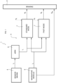
- Figure 1 shows a system 1 for controlling the jerk in an autonomous/automatic driving vehicle (not shown).
- the system 1 essentially comprises a braking system 2, a driving control module 3, sensor means 4, and processing means 5 configured to calculate, starting from the data received from the driving control module 3 and the sensor means 4, a signal for activating the braking system 2.
- the braking system 2 can be of any type, provided that it is configured to receive an electric input signal S S , S R , S EM generated by the processing means 5 or by the navigation module 3, as described in detail below.
- the sensor means 4 can comprise any type of sensors configured to measure the acceleration of the automatic/autonomous vehicle, such as for example accelerometers or an inertial unit.
- the sensor means 4 are therefore configured to generate an electric signal I A representing a value of the acceleration of the automatic/autonomous vehicle and transmit it to the processing means 5.
- the driving control module 3 may comprise an electronic unit of a known type configured to generate a plurality of signals configured to control the various actuators/vehicle control systems based on the data received from the sensors which aim to acquire vehicle operating data. Since these features are known, they will not be described in further detail.
- the control module 3 is configured to generate a braking signal I F configured to be sent to the processing means 5, under normal operating conditions of the vehicle, and an emergency braking signal S EM configured to be sent directly to the braking system 2 and to activate it accordingly.
- the emergency operation is characterized by an event that requires a braking level above the comfortable braking level, for example, an obstacle close in front of the vehicle, a failure of a main system or any other event classified as such by the safety analysis; it is the vehicle supervisor program that will have to decide based on events coded within the software.
- the processing means 5 comprise a jerk calculation module 6 configured to calculate the jerk value I J based on the signal I A received from the sensor means 4, and a plurality of operating modules 7 configured to modify the braking signal I F sent by the control module 3 based on the jerk value I J calculated by the jerk calculation module 6.
- the jerk calculation module 6 is configured to calculate the jerk value based on the acceleration signal I A processed by the sensor means through known mathematical/physical relationships.
- the modification of the signal I F by means of a respective operating module 7 can be carried out by means of a mathematical interpolation based on coefficients/tables stored in the respective operating module 7 and obtained by experimental tests.
- the signal I F can be simply limited as a function of a threshold value stored in the respective operating module 7.
- the operating modules 7 can be provided in a number proportional to the operating modes, that is to say, of gentleness or harshness in the variation of the acceleration, that are desired to be controlled in the vehicle.
- the system 1 comprises two operating modes, in particular a standard operating mode 7 and a fast operating mode 7, respectively, which can be selected based on signals U S , U R which can be emitted, for example, by the driving control module 3.
- the braking signal I F is modulated/limited as a function of the jerk signal I J to ensure the two safety conditions, i.e. that all the people standing in the vehicle are not in danger of falling during braking/acceleration, or to ensure a comfort condition, i.e. that the jerk of the vehicle shall not cause physical disturbances (e.g. nausea) to a significant percentage of the vehicle's passengers.
- the braking signal I F is modulated/limited as a function of the jerk signal I A so as to guarantee the safety condition alone, at the expense of the comfort condition.
- This situation can be useful under certain operating conditions, for example an object in the detection zone which implies a considerable braking action, yet still below the maximum braking performance, i.e. an uncomfortable but technically problem-free braking.
- processing means 5 can be realized through an electronic unit of the autonomous vehicle configured to receive the above-mentioned signals, process them in the same way based on the variables stored therein, and transmit the control signal to the braking system 2.
- This electronic unit can obviously be integrated into one of the driving 3 or braking system 2 control modules.
- the sensor means 4 detect the acceleration value I A which is used by the jerk calculation module 6 to process a jerk signal I J which is received by the operating module 7 selected on the basis of the signal Us, U R among the plurality of operating modules present.
- the latter also receives the desired braking signal I F from the control module 3.
- the selected operating module 7 will then modify the braking signal I F to provide a respective signal Ss, S R to the braking system 2, which will brake (or accelerate) accordingly. This variation will be detected by the sensor means 4 and the steps described below will be repeated continuously.
- control module 3 will send an emergency signal S EM to the braking system 2, which will brake directly, bypassing the processing of the processing means 5 described above.
- the method also comprises a step of direct emergency activation of the braking system 2, independently of the jerk signal I J , as described.
- the system described herein allows the jerk of an automatic/autonomous vehicle for public transport of people to be automatically controlled, while ensuring the safety and comfort of the passengers.
- control system described herein can be integrated into other electronic units intended for vehicle control, with consequent savings and optimizations.
- the methods of calculating the jerk or the modification of the braking signal can be any, according to the size and type of the automatic/autonomous driving vehicle for public transport of people.
- the operating modes 7 can be many, and the sensor means 4 can be of any type.
Landscapes
- Engineering & Computer Science (AREA)
- Transportation (AREA)
- Mechanical Engineering (AREA)
- Automation & Control Theory (AREA)
- Human Computer Interaction (AREA)
- Regulating Braking Force (AREA)
Description
- The present invention relates to a system and a method for controlling the jerk in an autonomous vehicle, in particular in an autonomous vehicle for public transport of passengers.
- In vehicles for public transport of people, i.e. in which some of the passengers may be standing during the vehicle's journey, it is known that the driver can control the acceleration to avoid jerking during the journey of the vehicle. In mathematics, the jerk is known as the derivative of the acceleration vector with respect to time, that is, the third derivative with respect to time of the position vector.
- This regulation becomes extremely important in autonomous vehicles that are increasingly widespread in the urban environment. It is clear that controlling the jerk is essential to increase the safety and comfort of passengers.
- One object of the present invention is therefore to propose a system and a method for automatically controlling the jerk in an automatic/autonomous vehicle, which allow maintenance of high levels of safety and comfort for the passengers.
- It is also an object of the present invention to provide a system and a method which are optimized and inexpensive.
- Example of prior art system and methods for controlling jerk in automatic/autonomous vehicle are
US2019023240 A1 ,JP2007009885 A1 JP2020006952 A1 US2019232970 A1 orUS9399449 A - The above mentioned objects are achieved by means of a system and a method according to the appended claims.
- Further features and advantages of the invention will become more apparent from the following description, given by way of illustrative, non-limiting example, with reference to the attached drawing which schematically shows a system for controlling the jerk according to the present invention.
-
Figure 1 shows a system 1 for controlling the jerk in an autonomous/automatic driving vehicle (not shown). - The system 1 essentially comprises a braking system 2, a driving control module 3, sensor means 4, and processing means 5 configured to calculate, starting from the data received from the driving control module 3 and the sensor means 4, a signal for activating the braking system 2.
- In particular, the braking system 2 can be of any type, provided that it is configured to receive an electric input signal SS, SR, SEM generated by the processing means 5 or by the navigation module 3, as described in detail below.
- The sensor means 4 can comprise any type of sensors configured to measure the acceleration of the automatic/autonomous vehicle, such as for example accelerometers or an inertial unit. The sensor means 4 are therefore configured to generate an electric signal IA representing a value of the acceleration of the automatic/autonomous vehicle and transmit it to the processing means 5.
- The driving control module 3 may comprise an electronic unit of a known type configured to generate a plurality of signals configured to control the various actuators/vehicle control systems based on the data received from the sensors which aim to acquire vehicle operating data. Since these features are known, they will not be described in further detail.
- With respect to the present invention, the control module 3 is configured to generate a braking signal IF configured to be sent to the
processing means 5, under normal operating conditions of the vehicle, and an emergency braking signal SEM configured to be sent directly to the braking system 2 and to activate it accordingly. The emergency operation is characterized by an event that requires a braking level above the comfortable braking level, for example, an obstacle close in front of the vehicle, a failure of a main system or any other event classified as such by the safety analysis; it is the vehicle supervisor program that will have to decide based on events coded within the software. - The processing means 5 comprise a jerk calculation module 6 configured to calculate the jerk value IJ based on the signal IA received from the sensor means 4, and a plurality of
operating modules 7 configured to modify the braking signal IF sent by the control module 3 based on the jerk value IJ calculated by the jerk calculation module 6. - In greater detail, the jerk calculation module 6 is configured to calculate the jerk value based on the acceleration signal IA processed by the sensor means through known mathematical/physical relationships. The modification of the signal IF by means of a
respective operating module 7 can be carried out by means of a mathematical interpolation based on coefficients/tables stored in therespective operating module 7 and obtained by experimental tests. Alternatively, the signal IF can be simply limited as a function of a threshold value stored in therespective operating module 7. - With regard to the
operating modules 7, they can be provided in a number proportional to the operating modes, that is to say, of gentleness or harshness in the variation of the acceleration, that are desired to be controlled in the vehicle. In the embodiment described herein, the system 1 comprises two operating modes, in particular astandard operating mode 7 and afast operating mode 7, respectively, which can be selected based on signals US, UR which can be emitted, for example, by the driving control module 3. - In the standard operating mode, the braking signal IF is modulated/limited as a function of the jerk signal IJ to ensure the two safety conditions, i.e. that all the people standing in the vehicle are not in danger of falling during braking/acceleration, or to ensure a comfort condition, i.e. that the jerk of the vehicle shall not cause physical disturbances (e.g. nausea) to a significant percentage of the vehicle's passengers.
- In the fast operating mode, the braking signal IF is modulated/limited as a function of the jerk signal IA so as to guarantee the safety condition alone, at the expense of the comfort condition. This situation can be useful under certain operating conditions, for example an object in the detection zone which implies a considerable braking action, yet still below the maximum braking performance, i.e. an uncomfortable but technically problem-free braking.
- It is clear that the processing means 5 can be realized through an electronic unit of the autonomous vehicle configured to receive the above-mentioned signals, process them in the same way based on the variables stored therein, and transmit the control signal to the braking system 2. This electronic unit can obviously be integrated into one of the driving 3 or braking system 2 control modules.
- The operation of the system 1 described above is as follows and is repeated continuously while the vehicle is being driven.
- As described above, the sensor means 4 detect the acceleration value IA which is used by the jerk calculation module 6 to process a jerk signal IJ which is received by the
operating module 7 selected on the basis of the signal Us, UR among the plurality of operating modules present. The latter also receives the desired braking signal IF from the control module 3. Theselected operating module 7 will then modify the braking signal IF to provide a respective signal Ss, SR to the braking system 2, which will brake (or accelerate) accordingly. This variation will be detected by the sensor means 4 and the steps described below will be repeated continuously. - If an emergency condition is detected, the control module 3 will send an emergency signal SEM to the braking system 2, which will brake directly, bypassing the processing of the processing means 5 described above.
- Based on the foregoing, it is clear that the invention of the present invention also relates to a jerk control method comprising the following steps:
- detecting an acceleration signal IA of the automatic/autonomous drive vehicle;
- calculating the jerk value of the vehicle IJ based on the acceleration signal IA detected;
- selecting a
braking modality 7 of the automatic/autonomous drive vehicle; - modifying/limiting a braking signal IF set by a control module 3 of the automatic/autonomous drive vehicle according to a selected
operating modality 7; - sending a modified braking signal Ss, SR to the braking system 2 of the automatic/autonomous vehicle.
- Parallel to the steps set out above, the method also comprises a step of direct emergency activation of the braking system 2, independently of the jerk signal IJ, as described.
- The steps of the method described above can be included in an electronic box of the vehicle, for example the ECU advantageously containing the same control module 3.
- The advantages of a jerk control system 1 and of a method according to the present invention are clearly evident from the foregoing.
- The system described herein allows the jerk of an automatic/autonomous vehicle for public transport of people to be automatically controlled, while ensuring the safety and comfort of the passengers.
- Moreover, the control system described herein can be integrated into other electronic units intended for vehicle control, with consequent savings and optimizations.
- Lastly, it is clear that modifications and variations may be made to the jerk control system 1 and the method according to the present invention, without however departing from the scope of protection defined by the claims.
- For example, it is clear that the methods of calculating the jerk or the modification of the braking signal can be any, according to the size and type of the automatic/autonomous driving vehicle for public transport of people.
- Similarly, as indicated, the
operating modes 7 can be many, and the sensor means 4 can be of any type.
Claims (11)
- A system (1) for controlling the jerk for an automatic/autonomous vehicle, said system comprising:- sensor means (4) configured to measure the acceleration of said vehicle and provide an electric signal (IA) indicating said acceleration,- a driving control module (3) of said vehicle configured to provide an electric braking signal (IF, SEM) and- a braking system (2) configured to brake said vehicle as a function of an electric input signal (Ss, SR, SEM),said system (1) comprising processing means (5) which comprise a jerk calculation module (6) configured to acquire said electric signal (IA) and calculate a jerk value (IJ) of said vehicle and a plurality of operating modules (7), each configured to acquire said electric braking signal (IF, SEM) and said jerk value (IJ), characterised in thatone of said plurality of operating modules (7) being selected by means of a selection signal (US, UR), said selected module modifying the electric braking signal (IF, SEM) as a function of said jerk value (IJ) and providing a modified electric braking signal (SS, SR) to said braking system (2).
- The system according to claim 1, wherein said selected operating module (7) limits said electric braking signal (IF, SEM) so as not to exceed a predetermined threshold value.
- The system according to claim 2, wherein said selected operating module (7) interpolates said electric braking signal (IF, SEM) by using the coefficients stored in said module.
- The system according to any one of the preceding claims, comprising a first and a second operating module (7), said second module sending a modified braking signal (SS, SR) to said braking system (2), to generate a jerk value (IJ) greater than the modified braking signal (SS, SR) with respect to said first operating module.
- The system according to any one of the preceding claims, wherein said detection means (4) comprise at least an accelerometer or an inertial unit.
- The system according to any one of the preceding claims, wherein said jerk calculation module (6) calculates said jerk value (IJ) based on mathematical/physical relationships stored in the latter.
- The system according to any one of the preceding claims, wherein said processing means (5) are integrated into said braking system (2) or into said driving control module (3).
- The system according to any one of the preceding claims, wherein said driving control module (3) is configured to send an emergency activation signal directly to said braking system (2) bypassing said processing means (5) in the case of an emergency.
- An automatic/autonomous driving vehicle for public transport of passengers, said vehicle comprising a braking system (2) and a jerk control system according to any one of the preceding claims.
- A method for controlling the jerk in an automatic/autonomous drive vehicle, comprising the following steps:• detecting an acceleration signal (IA) of an automatic/autonomous drive vehicle;• calculating the jerk value of the vehicle (IJ) based on the acceleration signal (IA) detected;• selecting a braking modality (7) of the automatic/autonomous drive vehicle;• modifying/limiting a braking signal (IF) set by a control module (3) of the automatic/autonomous drive vehicle according to a selected operating modality (7);• sending a modified braking signal (SS, SR) to the braking system (2) of said vehicle.
- The jerk control method according to claim 10, comprising a step of emergency activation of the braking system (2), said emergency activation step activating said braking system (2) independently of said jerk value (IJ).
Applications Claiming Priority (2)
| Application Number | Priority Date | Filing Date | Title |
|---|---|---|---|
| IT102020000000976A IT202000000976A1 (en) | 2020-01-20 | 2020-01-20 | SYSTEM AND METHOD FOR ADJUSTING THE STRATTONE IN AN AUTONOMOUS VEHICLE |
| PCT/IB2021/050414 WO2021148956A1 (en) | 2020-01-20 | 2021-01-20 | System and method for controlling the jerk for an automatic vehicle |
Publications (3)
| Publication Number | Publication Date |
|---|---|
| EP4093642A1 EP4093642A1 (en) | 2022-11-30 |
| EP4093642C0 EP4093642C0 (en) | 2023-11-01 |
| EP4093642B1 true EP4093642B1 (en) | 2023-11-01 |
Family
ID=70155209
Family Applications (1)
| Application Number | Title | Priority Date | Filing Date |
|---|---|---|---|
| EP21700648.5A Active EP4093642B1 (en) | 2020-01-20 | 2021-01-20 | System and method for controlling the jerk for an automatic vehicle |
Country Status (5)
| Country | Link |
|---|---|
| US (1) | US12233904B2 (en) |
| EP (1) | EP4093642B1 (en) |
| CN (1) | CN115397705A (en) |
| IT (1) | IT202000000976A1 (en) |
| WO (1) | WO2021148956A1 (en) |
Families Citing this family (1)
| Publication number | Priority date | Publication date | Assignee | Title |
|---|---|---|---|---|
| US12179727B2 (en) * | 2022-10-17 | 2024-12-31 | Ford Global Technologies, Llc | Vehicle brake control |
Family Cites Families (8)
| Publication number | Priority date | Publication date | Assignee | Title |
|---|---|---|---|---|
| JP4450220B2 (en) * | 2005-07-04 | 2010-04-14 | 株式会社デンソー | Engine control system |
| US8256851B2 (en) * | 2008-07-10 | 2012-09-04 | Robert Bosch Gmbh | Deceleration control for a vehicle |
| JP5927054B2 (en) * | 2012-06-11 | 2016-05-25 | 日立オートモティブシステムズ株式会社 | Vehicle travel control device |
| JP6493262B2 (en) * | 2016-03-18 | 2019-04-03 | 株式会社アドヴィックス | Vehicle control device |
| JP6597528B2 (en) * | 2016-09-08 | 2019-10-30 | 株式会社デンソー | Acceleration / deceleration control system, acceleration / deceleration control method |
| US20210213941A1 (en) * | 2018-09-27 | 2021-07-15 | Hitachi Automotive Systems, Ltd. | Vehicle Control Device |
| JP7135929B2 (en) * | 2019-02-20 | 2022-09-13 | トヨタ自動車株式会社 | Braking force controller |
| JP7133530B2 (en) * | 2019-10-17 | 2022-09-08 | ナブテスコオートモーティブ株式会社 | brake system |
-
2020
- 2020-01-20 IT IT102020000000976A patent/IT202000000976A1/en unknown
-
2021
- 2021-01-20 US US17/793,533 patent/US12233904B2/en active Active
- 2021-01-20 CN CN202180012441.1A patent/CN115397705A/en active Pending
- 2021-01-20 EP EP21700648.5A patent/EP4093642B1/en active Active
- 2021-01-20 WO PCT/IB2021/050414 patent/WO2021148956A1/en not_active Ceased
Also Published As
| Publication number | Publication date |
|---|---|
| EP4093642C0 (en) | 2023-11-01 |
| WO2021148956A1 (en) | 2021-07-29 |
| US12233904B2 (en) | 2025-02-25 |
| EP4093642A1 (en) | 2022-11-30 |
| US20230041429A1 (en) | 2023-02-09 |
| CN115397705A (en) | 2022-11-25 |
| IT202000000976A1 (en) | 2021-07-20 |
Similar Documents
| Publication | Publication Date | Title |
|---|---|---|
| EP3617017B1 (en) | Information processing apparatus | |
| US6607255B2 (en) | Collision mitigation by braking system | |
| US8396642B2 (en) | Adaptive cruise control system | |
| JP4354998B2 (en) | Automobile spacing control system | |
| US11392093B2 (en) | Prediction control device and method | |
| US11993276B2 (en) | Integrated control apparatus and method for normal and emergency control of vehicle | |
| US20140371981A1 (en) | Method and apparatus for operating a vehicle | |
| US10759474B2 (en) | Stowable steering wheel | |
| US20210237770A1 (en) | Vehicle control apparatus | |
| WO2019142563A1 (en) | Electronic control device | |
| CN104002811A (en) | Method for operating a motor vehicle driver assistance system with a combined longitudinal and transverse guiding function | |
| US20230192114A1 (en) | Method for Operating a Driver Assistance System of a Vehicle, Comprising Driver Moderation for Partially-Automated Functions, Driver Assistance System, and Vehicle | |
| EP2712782B1 (en) | Method and apparatus for performing driving assistance | |
| US20240025408A1 (en) | Vehicle control device | |
| WO2015057145A1 (en) | Method and system for controlling the acceleration process of a bus | |
| EP4093642B1 (en) | System and method for controlling the jerk for an automatic vehicle | |
| KR20190017339A (en) | Apparatus for storing information of autonomous vehicle and method thereof | |
| US9604610B2 (en) | Method for setting a limiting value of a vehicle state variable in the event of an accident | |
| CN102481848A (en) | Method and associated control system for controlling an adaptive heading control system | |
| CN118339068A (en) | Intelligent driving control method and device | |
| JP2000105900A (en) | Vehicle control device | |
| KR20160038158A (en) | Detecting system and Method of dangerous driving for driver tendency | |
| CN117184030A (en) | Vehicle occupant protection system self-diagnosis method and device | |
| KR101128271B1 (en) | Collision safety control device for vehicle | |
| KR20230004991A (en) | Vehicle driver erroneous operation prevention system and method |
Legal Events
| Date | Code | Title | Description |
|---|---|---|---|
| STAA | Information on the status of an ep patent application or granted ep patent |
Free format text: STATUS: UNKNOWN |
|
| STAA | Information on the status of an ep patent application or granted ep patent |
Free format text: STATUS: THE INTERNATIONAL PUBLICATION HAS BEEN MADE |
|
| PUAI | Public reference made under article 153(3) epc to a published international application that has entered the european phase |
Free format text: ORIGINAL CODE: 0009012 |
|
| STAA | Information on the status of an ep patent application or granted ep patent |
Free format text: STATUS: REQUEST FOR EXAMINATION WAS MADE |
|
| 17P | Request for examination filed |
Effective date: 20220719 |
|
| AK | Designated contracting states |
Kind code of ref document: A1 Designated state(s): AL AT BE BG CH CY CZ DE DK EE ES FI FR GB GR HR HU IE IS IT LI LT LU LV MC MK MT NL NO PL PT RO RS SE SI SK SM TR |
|
| DAV | Request for validation of the european patent (deleted) | ||
| DAX | Request for extension of the european patent (deleted) | ||
| GRAP | Despatch of communication of intention to grant a patent |
Free format text: ORIGINAL CODE: EPIDOSNIGR1 |
|
| STAA | Information on the status of an ep patent application or granted ep patent |
Free format text: STATUS: GRANT OF PATENT IS INTENDED |
|
| INTG | Intention to grant announced |
Effective date: 20230519 |
|
| GRAS | Grant fee paid |
Free format text: ORIGINAL CODE: EPIDOSNIGR3 |
|
| GRAA | (expected) grant |
Free format text: ORIGINAL CODE: 0009210 |
|
| STAA | Information on the status of an ep patent application or granted ep patent |
Free format text: STATUS: THE PATENT HAS BEEN GRANTED |
|
| AK | Designated contracting states |
Kind code of ref document: B1 Designated state(s): AL AT BE BG CH CY CZ DE DK EE ES FI FR GB GR HR HU IE IS IT LI LT LU LV MC MK MT NL NO PL PT RO RS SE SI SK SM TR |
|
| REG | Reference to a national code |
Ref country code: GB Ref legal event code: FG4D |
|
| REG | Reference to a national code |
Ref country code: CH Ref legal event code: EP |
|
| REG | Reference to a national code |
Ref country code: IE Ref legal event code: FG4D |
|
| REG | Reference to a national code |
Ref country code: DE Ref legal event code: R096 Ref document number: 602021006438 Country of ref document: DE |
|
| U01 | Request for unitary effect filed |
Effective date: 20231110 |
|
| U07 | Unitary effect registered |
Designated state(s): AT BE BG DE DK EE FI FR IT LT LU LV MT NL PT SE SI Effective date: 20231116 |
|
| U20 | Renewal fee for the european patent with unitary effect paid |
Year of fee payment: 4 Effective date: 20240115 |
|
| PG25 | Lapsed in a contracting state [announced via postgrant information from national office to epo] |
Ref country code: GR Free format text: LAPSE BECAUSE OF FAILURE TO SUBMIT A TRANSLATION OF THE DESCRIPTION OR TO PAY THE FEE WITHIN THE PRESCRIBED TIME-LIMIT Effective date: 20240202 |
|
| PG25 | Lapsed in a contracting state [announced via postgrant information from national office to epo] |
Ref country code: IS Free format text: LAPSE BECAUSE OF FAILURE TO SUBMIT A TRANSLATION OF THE DESCRIPTION OR TO PAY THE FEE WITHIN THE PRESCRIBED TIME-LIMIT Effective date: 20240301 |
|
| PG25 | Lapsed in a contracting state [announced via postgrant information from national office to epo] |
Ref country code: ES Free format text: LAPSE BECAUSE OF FAILURE TO SUBMIT A TRANSLATION OF THE DESCRIPTION OR TO PAY THE FEE WITHIN THE PRESCRIBED TIME-LIMIT Effective date: 20231101 |
|
| PG25 | Lapsed in a contracting state [announced via postgrant information from national office to epo] |
Ref country code: IS Free format text: LAPSE BECAUSE OF FAILURE TO SUBMIT A TRANSLATION OF THE DESCRIPTION OR TO PAY THE FEE WITHIN THE PRESCRIBED TIME-LIMIT Effective date: 20240301 Ref country code: GR Free format text: LAPSE BECAUSE OF FAILURE TO SUBMIT A TRANSLATION OF THE DESCRIPTION OR TO PAY THE FEE WITHIN THE PRESCRIBED TIME-LIMIT Effective date: 20240202 Ref country code: ES Free format text: LAPSE BECAUSE OF FAILURE TO SUBMIT A TRANSLATION OF THE DESCRIPTION OR TO PAY THE FEE WITHIN THE PRESCRIBED TIME-LIMIT Effective date: 20231101 |
|
| PG25 | Lapsed in a contracting state [announced via postgrant information from national office to epo] |
Ref country code: RS Free format text: LAPSE BECAUSE OF FAILURE TO SUBMIT A TRANSLATION OF THE DESCRIPTION OR TO PAY THE FEE WITHIN THE PRESCRIBED TIME-LIMIT Effective date: 20231101 Ref country code: PL Free format text: LAPSE BECAUSE OF FAILURE TO SUBMIT A TRANSLATION OF THE DESCRIPTION OR TO PAY THE FEE WITHIN THE PRESCRIBED TIME-LIMIT Effective date: 20231101 Ref country code: NO Free format text: LAPSE BECAUSE OF FAILURE TO SUBMIT A TRANSLATION OF THE DESCRIPTION OR TO PAY THE FEE WITHIN THE PRESCRIBED TIME-LIMIT Effective date: 20240201 Ref country code: HR Free format text: LAPSE BECAUSE OF FAILURE TO SUBMIT A TRANSLATION OF THE DESCRIPTION OR TO PAY THE FEE WITHIN THE PRESCRIBED TIME-LIMIT Effective date: 20231101 |
|
| PG25 | Lapsed in a contracting state [announced via postgrant information from national office to epo] |
Ref country code: CZ Free format text: LAPSE BECAUSE OF FAILURE TO SUBMIT A TRANSLATION OF THE DESCRIPTION OR TO PAY THE FEE WITHIN THE PRESCRIBED TIME-LIMIT Effective date: 20231101 |
|
| PG25 | Lapsed in a contracting state [announced via postgrant information from national office to epo] |
Ref country code: SK Free format text: LAPSE BECAUSE OF FAILURE TO SUBMIT A TRANSLATION OF THE DESCRIPTION OR TO PAY THE FEE WITHIN THE PRESCRIBED TIME-LIMIT Effective date: 20231101 |
|
| PG25 | Lapsed in a contracting state [announced via postgrant information from national office to epo] |
Ref country code: SM Free format text: LAPSE BECAUSE OF FAILURE TO SUBMIT A TRANSLATION OF THE DESCRIPTION OR TO PAY THE FEE WITHIN THE PRESCRIBED TIME-LIMIT Effective date: 20231101 Ref country code: SK Free format text: LAPSE BECAUSE OF FAILURE TO SUBMIT A TRANSLATION OF THE DESCRIPTION OR TO PAY THE FEE WITHIN THE PRESCRIBED TIME-LIMIT Effective date: 20231101 Ref country code: CZ Free format text: LAPSE BECAUSE OF FAILURE TO SUBMIT A TRANSLATION OF THE DESCRIPTION OR TO PAY THE FEE WITHIN THE PRESCRIBED TIME-LIMIT Effective date: 20231101 |
|
| REG | Reference to a national code |
Ref country code: DE Ref legal event code: R097 Ref document number: 602021006438 Country of ref document: DE |
|
| PG25 | Lapsed in a contracting state [announced via postgrant information from national office to epo] |
Ref country code: MC Free format text: LAPSE BECAUSE OF FAILURE TO SUBMIT A TRANSLATION OF THE DESCRIPTION OR TO PAY THE FEE WITHIN THE PRESCRIBED TIME-LIMIT Effective date: 20231101 |
|
| PG25 | Lapsed in a contracting state [announced via postgrant information from national office to epo] |
Ref country code: MC Free format text: LAPSE BECAUSE OF FAILURE TO SUBMIT A TRANSLATION OF THE DESCRIPTION OR TO PAY THE FEE WITHIN THE PRESCRIBED TIME-LIMIT Effective date: 20231101 |
|
| REG | Reference to a national code |
Ref country code: CH Ref legal event code: PL |
|
| PLBE | No opposition filed within time limit |
Free format text: ORIGINAL CODE: 0009261 |
|
| STAA | Information on the status of an ep patent application or granted ep patent |
Free format text: STATUS: NO OPPOSITION FILED WITHIN TIME LIMIT |
|
| 26N | No opposition filed |
Effective date: 20240802 |
|
| PG25 | Lapsed in a contracting state [announced via postgrant information from national office to epo] |
Ref country code: CH Free format text: LAPSE BECAUSE OF NON-PAYMENT OF DUE FEES Effective date: 20240131 |
|
| PG25 | Lapsed in a contracting state [announced via postgrant information from national office to epo] |
Ref country code: CH Free format text: LAPSE BECAUSE OF NON-PAYMENT OF DUE FEES Effective date: 20240131 |
|
| PG25 | Lapsed in a contracting state [announced via postgrant information from national office to epo] |
Ref country code: IE Free format text: LAPSE BECAUSE OF NON-PAYMENT OF DUE FEES Effective date: 20240120 |
|
| PG25 | Lapsed in a contracting state [announced via postgrant information from national office to epo] |
Ref country code: IE Free format text: LAPSE BECAUSE OF NON-PAYMENT OF DUE FEES Effective date: 20240120 |
|
| U20 | Renewal fee for the european patent with unitary effect paid |
Year of fee payment: 5 Effective date: 20250120 |
|
| PG25 | Lapsed in a contracting state [announced via postgrant information from national office to epo] |
Ref country code: RO Free format text: LAPSE BECAUSE OF FAILURE TO SUBMIT A TRANSLATION OF THE DESCRIPTION OR TO PAY THE FEE WITHIN THE PRESCRIBED TIME-LIMIT Effective date: 20231101 |
|
| PG25 | Lapsed in a contracting state [announced via postgrant information from national office to epo] |
Ref country code: CY Free format text: LAPSE BECAUSE OF FAILURE TO SUBMIT A TRANSLATION OF THE DESCRIPTION OR TO PAY THE FEE WITHIN THE PRESCRIBED TIME-LIMIT; INVALID AB INITIO Effective date: 20210120 |
|
| PG25 | Lapsed in a contracting state [announced via postgrant information from national office to epo] |
Ref country code: HU Free format text: LAPSE BECAUSE OF FAILURE TO SUBMIT A TRANSLATION OF THE DESCRIPTION OR TO PAY THE FEE WITHIN THE PRESCRIBED TIME-LIMIT; INVALID AB INITIO Effective date: 20210120 |
|
| GBPC | Gb: european patent ceased through non-payment of renewal fee |
Effective date: 20250120 |
|
| PG25 | Lapsed in a contracting state [announced via postgrant information from national office to epo] |
Ref country code: GB Free format text: LAPSE BECAUSE OF NON-PAYMENT OF DUE FEES Effective date: 20250120 |
|
| PG25 | Lapsed in a contracting state [announced via postgrant information from national office to epo] |
Ref country code: TR Free format text: LAPSE BECAUSE OF FAILURE TO SUBMIT A TRANSLATION OF THE DESCRIPTION OR TO PAY THE FEE WITHIN THE PRESCRIBED TIME-LIMIT Effective date: 20231101 |
|
| U20 | Renewal fee for the european patent with unitary effect paid |
Year of fee payment: 6 Effective date: 20251211 |