EP4093562B1 - Transfer machine - Google Patents
Transfer machine Download PDFInfo
- Publication number
- EP4093562B1 EP4093562B1 EP21703551.8A EP21703551A EP4093562B1 EP 4093562 B1 EP4093562 B1 EP 4093562B1 EP 21703551 A EP21703551 A EP 21703551A EP 4093562 B1 EP4093562 B1 EP 4093562B1
- Authority
- EP
- European Patent Office
- Prior art keywords
- advance
- tool holder
- rotation
- stem
- holder element
- Prior art date
- Legal status (The legal status is an assumption and is not a legal conclusion. Google has not performed a legal analysis and makes no representation as to the accuracy of the status listed.)
- Active
Links
Images



Classifications
-
- B—PERFORMING OPERATIONS; TRANSPORTING
- B21—MECHANICAL METAL-WORKING WITHOUT ESSENTIALLY REMOVING MATERIAL; PUNCHING METAL
- B21D—WORKING OR PROCESSING OF SHEET METAL OR METAL TUBES, RODS OR PROFILES WITHOUT ESSENTIALLY REMOVING MATERIAL; PUNCHING METAL
- B21D19/00—Flanging or other edge treatment, e.g. of tubes
-
- B—PERFORMING OPERATIONS; TRANSPORTING
- B21—MECHANICAL METAL-WORKING WITHOUT ESSENTIALLY REMOVING MATERIAL; PUNCHING METAL
- B21D—WORKING OR PROCESSING OF SHEET METAL OR METAL TUBES, RODS OR PROFILES WITHOUT ESSENTIALLY REMOVING MATERIAL; PUNCHING METAL
- B21D41/00—Application of procedures in order to alter the diameter of tube ends
-
- B—PERFORMING OPERATIONS; TRANSPORTING
- B21—MECHANICAL METAL-WORKING WITHOUT ESSENTIALLY REMOVING MATERIAL; PUNCHING METAL
- B21D—WORKING OR PROCESSING OF SHEET METAL OR METAL TUBES, RODS OR PROFILES WITHOUT ESSENTIALLY REMOVING MATERIAL; PUNCHING METAL
- B21D43/00—Feeding, positioning or storing devices combined with, or arranged in, or specially adapted for use in connection with, apparatus for working or processing sheet metal, metal tubes or metal profiles; Associations therewith of cutting devices
- B21D43/02—Advancing work in relation to the stroke of the die or tool
- B21D43/04—Advancing work in relation to the stroke of the die or tool by means in mechanical engagement with the work
- B21D43/14—Advancing work in relation to the stroke of the die or tool by means in mechanical engagement with the work by turning devices, e.g. turn-tables
-
- B—PERFORMING OPERATIONS; TRANSPORTING
- B23—MACHINE TOOLS; METAL-WORKING NOT OTHERWISE PROVIDED FOR
- B23Q—DETAILS, COMPONENTS, OR ACCESSORIES FOR MACHINE TOOLS, e.g. ARRANGEMENTS FOR COPYING OR CONTROLLING; MACHINE TOOLS IN GENERAL CHARACTERISED BY THE CONSTRUCTION OF PARTICULAR DETAILS OR COMPONENTS; COMBINATIONS OR ASSOCIATIONS OF METAL-WORKING MACHINES, NOT DIRECTED TO A PARTICULAR RESULT
- B23Q39/00—Metal-working machines incorporating a plurality of sub-assemblies, each capable of performing a metal-working operation
- B23Q39/04—Metal-working machines incorporating a plurality of sub-assemblies, each capable of performing a metal-working operation the sub-assemblies being arranged to operate simultaneously at different stations, e.g. with an annular work-table moved in steps
- B23Q39/042—Metal-working machines incorporating a plurality of sub-assemblies, each capable of performing a metal-working operation the sub-assemblies being arranged to operate simultaneously at different stations, e.g. with an annular work-table moved in steps with circular arrangement of the sub-assemblies
- B23Q39/044—Metal-working machines incorporating a plurality of sub-assemblies, each capable of performing a metal-working operation the sub-assemblies being arranged to operate simultaneously at different stations, e.g. with an annular work-table moved in steps with circular arrangement of the sub-assemblies having at least one tool station cooperating with each work holder, e.g. multi-spindle lathes
-
- Y—GENERAL TAGGING OF NEW TECHNOLOGICAL DEVELOPMENTS; GENERAL TAGGING OF CROSS-SECTIONAL TECHNOLOGIES SPANNING OVER SEVERAL SECTIONS OF THE IPC; TECHNICAL SUBJECTS COVERED BY FORMER USPC CROSS-REFERENCE ART COLLECTIONS [XRACs] AND DIGESTS
- Y10—TECHNICAL SUBJECTS COVERED BY FORMER USPC
- Y10T—TECHNICAL SUBJECTS COVERED BY FORMER US CLASSIFICATION
- Y10T29/00—Metal working
- Y10T29/51—Plural diverse manufacturing apparatus including means for metal shaping or assembling
- Y10T29/5124—Plural diverse manufacturing apparatus including means for metal shaping or assembling with means to feed work intermittently from one tool station to another
- Y10T29/5127—Blank turret
- Y10T29/5129—Rotary work - horizontal axis
Definitions
- the present invention refers to the field of transfer machines; in particular, the present invention relates to a transfer machine for cold plastic deformation and/or chip removal processing of at least one tubular profile. Such processed tubular profiles are then intended for the technical automotive sector or the thermo-hydraulic sector.
- Transfer machines for cold forming of tubular profiles using pneumatically or hydrodynamically actuated work units are known in the prior art. Indeed, the transfer machines of the prior art obtain the necessary thrust forces for the cold plastic deformation of tubular profiles with variable diameter and thickness by using pneumatic or hydrodynamic actuators.
- Transfer machines that use mixed actuation work units, i.e., partly electromechanical and partly pneumatic/hydrodynamic are also known. Such transfer machines require the electromechanical actuator to be replaced by at least one pneumatic and/or hydrodynamic actuator capable of generating sufficient thrust to deform the tubular profile during the deformation process.
- a transfer machine comprising circuits for pressurized fluids is not only structurally complex but also dangerous. Indeed, the mechanical components delivering pressurized fluids require higher safety standards, continuous monitoring and frequent maintenance. Compliance with such safety standards results in higher costs to ensure the correct and safe operation of the transfer machine.
- a plurality of housing seats 121 are formed in the mounting table 12 and each housing seat of such a plurality of housing seats 121 faces a respective work station.
- Each housing seat is further suitable for accommodating an electromechanical work unit of said plurality of electromechanical work units.
- Each electromechanical work unit 2;3;4;5 comprises a first advance group 21;31;41;51.
- a first advance group comprises, in turn, a first advance motor 22;32;42;52, a first advance recirculating ball screw 23;33;43;53, a first advance nut 24;34;44;54 and a first tubular stem 25;35;45;55.
- the first advance motor 22;32;42;52 is electric.
- the first advance recirculating ball screw 23;33;43;53 is moved by the first advance motor and extends along a first advance screw axis V' which is substantially orthogonal to the mounting table 12.
- the first advance nut 24;34;44;54 is engaged by the first advance recirculating ball screw and is translable along the first advance screw axis V'.
- the first tubular stem 25;35;45;55 extends between a first stem proximal end 25';35';45';55' and a first stem distal end 25";35";45”;55".
- the first stem proximal end is engaged to the first advance nut and made integral therewith while the first stem distal end is suitable for defining the advancement and/or positioning of a first tool holder element 36;46;56.
- proximal identifies an element which is close to, or that stretches towards a generic motor member.
- distal identifies an element which is far, or distanced, from the generic motor member.
- the electromechanical work unit 2 has a maximum linear stroke of 150 mm.
- the electromechanical work unit 3 is suitable for generating a rototranslational motion.
- the first advance motor 32 generates an axial thrust motion with a maximum stroke of 150 mm, while the rotation motor 321 defines the rotation of the first tool holder element 36.
- the tool holder element hub 327 is further keyed onto the first tool holder element 36 to define the rotation of said first tool holder element 36 about the tool holder element rotation axis R.
- the first tubular stem 35 comprises a first stem first portion and a first stem second portion.
- the first stem first portion extends from the first stem proximal end 35' and the first stem second portion terminates with the first stem distal end 35".
- the cross-section dimensions of the first stem first portion are different from the cross-section dimensions of the second stem second portion.
- the first stem first portion is connected to the first stem second portion by a stem connection flange.
- the electromechanical work unit 4 is suitable for generating a rototranslational motion.
- the first advance motor 42 generates an axial position motion with a maximum stroke of 100 mm, while the rotation motor 421 defines the rotation of the first tool holder element 46.
- the tool holder element hub 427 is further keyed onto the first tool holder element 46 to define the rotation of said first tool holder element 46 about the tool holder element rotation axis R.
- the second advance recirculating ball screw 531 extends along a second advance screw axis V" which is parallel to the first advance screw axis V'. Furthermore, such a second advance recirculating ball screw is moved by the second advance motor 521.
- the second advance nut 541 is engaged by the second advance recirculating ball screw 531 and is translable along the second advance screw axis V".
- the second advance flange 542 is engaged to the second advance nut 541 and made integral therewith.
- the second tubular stem 551 extends between a second stem proximal end 551' and a second stem distal end 551".
- first collar 240;340;440;540 defines an engagement surface for the first stem proximal end 25' or for a first advance flange 350;450;550 which is engaged to both the first advance nut 24;34;44;54 and the first stem proximal end 35';45';55' and made integral therewith.
- the first tool holder seat 25";35";45” is obtained at the first stem distal end 260;360;460.
- the first tool holder element 36;46 is a shaft in which a tool seat 361;461 is centrally formed suitable for housing a forming unit or a chip removal unit.
- the bellows joint allows the correction of possible misalignments between the second advance motor and the second advance recirculating ball screw. Therefore, the bellows joint facilitates the assembly of the electromechanical work unit.
- a second tool holder seat 560 suitable for housing the second tool holder element is obtained at the second stem distal end 551".
- Such a second tool holder element is removably equippable with at least one tool for plastic deformation or for chip removal of the tubular profile.
- the transfer machine further comprises a first rotation motion transmission system 413.
- a first rotation motion transmission system 413 comprises a first rotation driving pulley 414, a first rotation driven pulley 415 and a first rotation transmission belt 416.
- the first rotation driving pulley 414 is engaged to a first rotation driving shaft 411 of the first advance motor 42.
- the first rotation transmission belt 416 transmits the motion from the first rotation driving pulley 414 to the first rotation driven pulley 415.
- the first rotation driven pulley 415 is engaged to the first advancement recirculating ball screw 43 and made integral therewith.
- the first rotation driving shaft 411 extends along a first advance motor axis M' which is either parallel to or coincident with the first advance screw axis V'.
- the first tool holder element 36 is provided with a first centering tang 3431 protruding proximally towards the first advance motor 32 along the first advance screw axis V'.
- Said first centering tang 3431 is at least partially housed in a first recess 330 obtained in the first advancement recirculating ball screw 33.
- Said first recess 330 is circumferentially delimited by a first recess wall and the first centering tang 3431 is never in contact with said first recess wall.
- the first recess 330 is simply a notch for housing the first centering tang 3431 and there is no contact between the first centering tang 3431 and the first recess wall.
- the external covering frame being made of aluminum, allows obtaining an electromechanical work unit, which is light enough to be installed cantilevered in the housing of the mounting table.
- the second advantage is that the transfer machine allows a reduction in costs due to the fact that the work units are completely electromechanical.
- the structure of the transfer machine is simplified because the electromechanical work units are not equipped with oil or fluid pressure tanks, control units or oil/fluid recovery systems.
- a further cost reduction is attributable to the fact that there is no need to dispose of the waste oil produced by the use of electromechanical work units and that the transfer machine requires less monitoring and maintenance than a transfer machine with completely pneumatic or hydrodynamic actuation.
Landscapes
- Engineering & Computer Science (AREA)
- Mechanical Engineering (AREA)
- Transmission Devices (AREA)
- Press Drives And Press Lines (AREA)
- Threshing Machine Elements (AREA)
- Iron Core Of Rotating Electric Machines (AREA)
- Manufacturing And Processing Devices For Dough (AREA)
Description
- The present invention refers to the field of transfer machines; in particular, the present invention relates to a transfer machine for cold plastic deformation and/or chip removal processing of at least one tubular profile. Such processed tubular profiles are then intended for the technical automotive sector or the thermo-hydraulic sector.
- Transfer machines for cold forming of tubular profiles using pneumatically or hydrodynamically actuated work units are known in the prior art. Indeed, the transfer machines of the prior art obtain the necessary thrust forces for the cold plastic deformation of tubular profiles with variable diameter and thickness by using pneumatic or hydrodynamic actuators.
- Transfer machines that use mixed actuation work units, i.e., partly electromechanical and partly pneumatic/hydrodynamic are also known. Such transfer machines require the electromechanical actuator to be replaced by at least one pneumatic and/or hydrodynamic actuator capable of generating sufficient thrust to deform the tubular profile during the deformation process.
- The presence of supply circuits for pressurized fluids is still necessary in both of the aforesaid cases, whether the transfer machine is actuated entirely by actuators fed by pressurized fluids or has a mixed actuation integrating electromechanical and pneumatic/hydrodynamic actuators.
- It is known that the presence of conduits or supply circuits for feeding pressurized fluids complicates the design and assembly of the transfer machine. An example of a transfer machine for mechanical processing according to the prior art is described in
WO2018/172952A1 . - Disadvantageously, a transfer machine comprising circuits for pressurized fluids is not only structurally complex but also dangerous. Indeed, the mechanical components delivering pressurized fluids require higher safety standards, continuous monitoring and frequent maintenance. Compliance with such safety standards results in higher costs to ensure the correct and safe operation of the transfer machine.
- It is the object of the present invention to suggest a transfer machine for cold plastic deformation and/or chip removal processing capable of avoiding, at least in part, the drawbacks complained above relative to the transfer machines according to the prior art.
- Said object is achieved by a transfer machine for cold plastic deformation and/or chip removal processing according to
claim 1. The dependent claims describe preferred embodiments of the invention. - The features and advantages of the transfer machine according to the invention will be apparent from the following description which illustrates preferred embodiments, given by way of indicative, non-limiting examples, with reference to the accompanying figures, in which:
-
figure 1 shows a perspective view of a transfer machine according to the invention; -
figure 2 shows a further perspective view of the transfer machine infigure 1 ; -
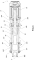
figure 3 shows an electromechanical work unit according to a further embodiment; -
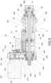
figure 4 shows the electromechanical work unit according to a further embodiment; -
figure 5 shows the electromechanical work unit according to a yet further embodiment, and -
figure 6 shows the electromechanical work unit according to a further embodiment. - In said drawings, a transfer machine according to the invention is indicated by
reference numeral 1 as a whole. - In a general embodiment, a
transfer machine 1 for cold plastic deformation and/or chip removal processing of at least one tubular profile is suggested. Such a transfer machine comprises abase 11, a mounting table 12, a rotary table 13 and a plurality ofelectromechanical work units 2;3;4;5. Thebase 11 allows the resting on a base surface B. The mounting table 12 is fixed and arranged orthogonally to the base plane B. The rotary table 13 faces the mounting table. Theelectromechanical work units 2;3;4;5 are installed on said mounting table 12. - The rotary table 13 comprises a plurality of
work stations 131, where each work station of said plurality of work stations comprises avise 132 for clamping the tubular profile. - According to an embodiment, the
vise 132 comprises a pair of half-jaws, wherein the first half-jaw of said pair of half-jaws is fixed and the second half-jaw is movable. - Advantageously, the movable half-jaw adapts to the possible variations of the diameter of the tubular profile to be processed, making the transfer machine flexible relative to the various types of tubular profiles.
- According to the invention, a plurality of
housing seats 121 are formed in the mounting table 12 and each housing seat of such a plurality ofhousing seats 121 faces a respective work station. Each housing seat is further suitable for accommodating an electromechanical work unit of said plurality of electromechanical work units. - Each
electromechanical work unit 2;3;4;5 comprises afirst advance group 21;31;41;51. Such a first advance group comprises, in turn, afirst advance motor 22;32;42;52, a first advance recirculatingball screw 23;33;43;53, afirst advance nut 24;34;44;54 and a firsttubular stem 25;35;45;55. - According to the invention, the
first advance motor 22;32;42;52 is electric. - According to the invention, the first advance recirculating
ball screw 23;33;43;53 is moved by the first advance motor and extends along a first advance screw axis V' which is substantially orthogonal to the mounting table 12. Thefirst advance nut 24;34;44;54 is engaged by the first advance recirculating ball screw and is translable along the first advance screw axis V'. The firsttubular stem 25;35;45;55 extends between a first stem proximal end 25';35';45';55' and a first stemdistal end 25";35";45";55". The first stem proximal end is engaged to the first advance nut and made integral therewith while the first stem distal end is suitable for defining the advancement and/or positioning of a firsttool holder element 36;46;56. - In the present discussion, the term "proximal" identifies an element which is close to, or that stretches towards a generic motor member. Conversely, the term "distal" identifies an element which is far, or distanced, from the generic motor member.
- The at least one tubular profile can be made of a material belonging to the steel or aluminum alloy family.
- According to an embodiment shown in the accompanying
figures 3 ,4 and6 , thefirst advance motor 22;32;52, the first advance recirculatingball screw 23;33;53, thefirst advance nut 24;34;54 and the firsttubular stem 25;35;55 are coaxial. - According to the embodiment shown in
figure 3 , theelectromechanical work unit 2 has a maximum linear stroke of 150 mm. - According to an embodiment shown in the accompanying
figures 4 and5 , the at least oneelectromechanical work unit 3;4 further comprises arotation group 311;411. Saidrotation group 311;411 comprises arotation motor 321;421, a firsttool holder element 36;46 and a rotationmotion transmission system 323;423. Therotation motor 321; 421 comprises, in turn, arotation motor shaft 322;422 which extends along a rotation motor axis M" parallel to the first advance screw axis V'. The firsttool holder element 36;46 is provided with a toolholder element hub 327;427. The rotationmotion transmission system 323;423 comprises transmission means suitable for connecting therotation motor 321;421 to the toolholder element hub 327;427. In particular, the toolholder element hub 327;427 defines the rotation of the firsttool holder element 36;46 about a tool holder element rotation axis R which is either parallel or coaxial to the first advance screw axis V'. - According to the accompanying
figures 4 and5 , the transmission means comprise arotation driving pulley 324;424, a rotation drivenpulley 325;425, and arotation transmission belt 326;426. Therotation driving pulley 324;424 is engaged to therotation driving shaft 322;422. Therotation transmission belt 326;426 allows the transmission of rotation motion from therotation driving pulley 324;424 to the rotation drivenpulley 325;425. In detail, the toolholder element hub 327; 427 is engaged to the rotation drivenpulley 325;425 and made integral therewith. - According to the embodiment shown in
figure 4 , theelectromechanical work unit 3 is suitable for generating a rototranslational motion. In particular, thefirst advance motor 32 generates an axial thrust motion with a maximum stroke of 150 mm, while therotation motor 321 defines the rotation of the firsttool holder element 36. The toolholder element hub 327 is further keyed onto the firsttool holder element 36 to define the rotation of said firsttool holder element 36 about the tool holder element rotation axis R. - According to an embodiment, the first
tubular stem 35 comprises a first stem first portion and a first stem second portion. The first stem first portion extends from the first stem proximal end 35' and the first stem second portion terminates with the first stemdistal end 35". The cross-section dimensions of the first stem first portion are different from the cross-section dimensions of the second stem second portion. Furthermore, the first stem first portion is connected to the first stem second portion by a stem connection flange. - According to the embodiment shown in
figure 5 , theelectromechanical work unit 4 is suitable for generating a rototranslational motion. In particular, thefirst advance motor 42 generates an axial position motion with a maximum stroke of 100 mm, while therotation motor 421 defines the rotation of the firsttool holder element 46. The toolholder element hub 427 is further keyed onto the firsttool holder element 46 to define the rotation of said firsttool holder element 46 about the tool holder element rotation axis R. - According to the embodiment shown in
figure 6 , the at least one electromechanical work unit 5 further comprises asecond advance group 511. Saidsecond advance group 511 comprises asecond advance motor 521, a second advance recirculatingball screw 531, asecond advance nut 541, asecond advance flange 542 and a secondtubular stem 551. - The second advance recirculating
ball screw 531 extends along a second advance screw axis V" which is parallel to the first advance screw axis V'. Furthermore, such a second advance recirculating ball screw is moved by thesecond advance motor 521. Thesecond advance nut 541 is engaged by the second advance recirculatingball screw 531 and is translable along the second advance screw axis V". Thesecond advance flange 542 is engaged to thesecond advance nut 541 and made integral therewith. The secondtubular stem 551 extends between a second stem proximal end 551' and a second stemdistal end 551". The second stem proximal end is engaged to thesecond advancement flange 542 and made integral therewith while the second stem distal end is suitable for defining the advancement and/or positioning of a second tool holder element. In particular, the secondtubular stem 551 is coaxial to the firsttubular stem 55. - The electromechanical work unit 5 shown in
figure 6 is suitable for generating two mutually independent axial motions. In detail, the first axial thrust motion is generated by means of the firsttubular stem 55 while the second axial thrust motion is generated by the secondtubular stem 551. It is worth noting that the order of performance of the two axial motions is reversible, i.e., the thrust of the firsttubular stem 55 may precede that of the secondtubular stem 551 or vice versa. - According to the embodiment shown in
figure 6 , the electromechanical work unit 5 is suitable for generating two independent axial motions to perform two different deformation processes on the tubular profile, e.g. an external deformation and an internal deformation of the tubular profile. In detail, the stroke of the firsttubular stem 55 and/or secondtubular stem 551 varies from a minimum of 49 mm to a maximum of 160 mm. - According to an embodiment, the
first advance nut 24;34;44;54 is substantially a hollow cylinder which extends between an advance nut proximal end 24';34';44';54' and a first advance nutdistal end 24";34";44";54". Thefirst advance nut 24;34;44;54 is further provided with afirst collar 240;340;440;540 which protrudes radially outwards and is formed at the first advance nut proximal end (figures 3 and5 ) or the first advance nut distal end (figures 4 and6 ). In other words, when the first collar protrudes from the first advance nut distal end, the first advance nut is substantially reverse mounted. - Advantageously, it is possible to reduce the axial dimensions of the electromechanical work unit when the first advance nut is mounted upside down.
- Furthermore, the
first collar 240;340;440;540 defines an engagement surface for the first stem proximal end 25' or for afirst advance flange 350;450;550 which is engaged to both thefirst advance nut 24;34;44;54 and the first stem proximal end 35';45';55' and made integral therewith. - According to an embodiment shown in
figures 4 and6 , thefirst advance flange 350;550 is axially symmetrical. In particular, afirst flange hole 3500;5500 is engaged by the first advance recirculatingball screw 33;53 is centrally formed in thefirst advance flange 350;550. Saidfirst flange hole 3500;5500 comprises a steppedchamfer 3501;5501 suitable for engaging thefirst advance flange 350;550 to thefirst advance nut 34;54 and make it integral therewith. Thefirst advance flange 350;550 is further delimited by a firstflange perimeter region 3502;5502 suitable for engaging thefirst advance flange 350;550 to the first stem proximal end 35';55' and make it integral therewith. - According to an embodiment, the first
tool holder seat 25";35";45" is obtained at the first stemdistal end 260;360;460. - According to the accompanying
figures 3 , the firsttool holder seat 260 is suitable for housing a plastic deformation unit or a chip removal unit. For example, the plastic deformation unit is a rolling unit, or a heading, rounding or facing unit. - According to the accompanying
figures 4 and5 , the firsttool holder seat 360;460 is suitable for housing the firsttool holder element 36;46. Such a firsttool holder element 36;46 is suitable for being removably equippable with at least one tool for cold plastic deformation or for chip removal of the tubular profile. - According to the embodiment shown in
figures 4 and5 , the firsttool holder element 36;46 is a shaft in which atool seat 361;461 is centrally formed suitable for housing a forming unit or a chip removal unit. - According to the embodiment in
figure 6 , the firsttool holder element 56 forms releasable coupling means 561, e.g. a shape coupling, by interference or bolted with the deformation unit. - According to the embodiment shown in
figure 6 , the first stemdistal end 55" is engaged to an advance flangetool holder element 543 and made integral therewith. A blindtool holder element 5430 housing the firsttool holder element 56 is obtained in the advance flange oftool holder element 543. - Advantageously, the
tool element seat 5430 promotes the centering of thefirst tool element 56 relative to the tool holderelement advance flange 543. - The tool holder
element advance flange 543 is further integral with the firsttool holder element 56 and is provided with a centeringtang 5431 which protrudes proximally towards thefirst advance motor 52 along the first advance screw axis V'. Said centeringtang 5431 is at least partially housed in arecess 530 obtained in the first advancement recirculatingball screw 53.Said recess 530 is circumferentially delimited by a recess wall and the centeringtang 5431 is never in contact with said recess wall. In other words, therecess 530 is simply a notch for housing the centeringtang 5431 and there is no contact between the centeringtang 5431 and the recess wall. - According to the embodiment shown in
figure 6 , thesecond advance motor 521 is engaged to the second advance recirculatingball screw 531 by means of a bellows joint 571. - Advantageously, the bellows joint allows the correction of possible misalignments between the second advance motor and the second advance recirculating ball screw. Therefore, the bellows joint facilitates the assembly of the electromechanical work unit.
- According to a further advantageous aspect, the bellows joint improves the torsional resistance at the interface between the second advance motor and the second advance recirculating ball screw.
- According to the accompanying
figure 6 , thesecond advance nut 541 is provided with asecond collar 5410 suitable for engaging thesecond advance nut 541 and make it integral with thesecond advance flange 542. - According to an embodiment shown in
figure 6 , a secondtool holder seat 560 suitable for housing the second tool holder element is obtained at the second stemdistal end 551". Such a second tool holder element is removably equippable with at least one tool for plastic deformation or for chip removal of the tubular profile. - According to an embodiment shown in
figure 5 , the transfer machine further comprises a first rotationmotion transmission system 413. Such a first rotationmotion transmission system 413 comprises a firstrotation driving pulley 414, a first rotation drivenpulley 415 and a firstrotation transmission belt 416. The firstrotation driving pulley 414 is engaged to a firstrotation driving shaft 411 of thefirst advance motor 42. The firstrotation transmission belt 416 transmits the motion from the firstrotation driving pulley 414 to the first rotation drivenpulley 415. Furthermore, the first rotation drivenpulley 415 is engaged to the first advancement recirculatingball screw 43 and made integral therewith. The firstrotation driving shaft 411 extends along a first advance motor axis M' which is either parallel to or coincident with the first advance screw axis V'. - According to the embodiment shown in the accompanying
figure 4 , the firsttool holder element 36 is provided with a first centeringtang 3431 protruding proximally towards thefirst advance motor 32 along the first advance screw axis V'. Said first centeringtang 3431 is at least partially housed in afirst recess 330 obtained in the first advancement recirculatingball screw 33. Saidfirst recess 330 is circumferentially delimited by a first recess wall and the first centeringtang 3431 is never in contact with said first recess wall. In other words, thefirst recess 330 is simply a notch for housing the first centeringtang 3431 and there is no contact between the first centeringtang 3431 and the first recess wall. - According to the invention, each
electromechanical work unit 2;3;4;5 comprises anexternal covering frame 200;300;400;500 made of anodized aluminum, e.g. aluminum of the 7000 series. In particular, the external covering frame is made of hard-anodized aluminum. The hard anodizing process makes it possible to obtain a hardened surface layer with a depth comprised between 20 and 35 microns. - Advantageously, the external covering frame, being made of aluminum, allows obtaining an electromechanical work unit, which is light enough to be installed cantilevered in the housing of the mounting table.
- According to a further advantageous aspect, the external covering frame, being made of anodized aluminum, allows obtaining a good compromise between superficial hardness and lightness.
- According to the invention shown in the accompanying
figures 3 ,4 and6 , thefirst advance motor 22;32;52 is a hollow shaft motor. - According to an embodiment, each
electromechanical work unit 2;3;4;5 comprises anexternal covering frame 200;300;400;500 which extends between a proximal frame portion 200';300';400';500' and adistal frame portion 200";300";400";500". Thedistal frame portion 200";300";400";500" comprises an externalcylindrical surface 201;301;401;501 proximally delimited by ashoulder 210;310;410;510, or a spacer, and distally delimited by a lockingring nut 220;320;420;520. The space region extending between theshoulder 210;310;410;510, or the spacer, and the lockingring nut 220;320;420;520 is suitable for being housed in one of the plurality ofhousing seats 121 of the mounting table 12. In particular, the lockingring nut 220;320;420;520 is screwed onto the externalcylindrical surface 201;301;401;501 until it comes into contact with the surface of the mounting table 12 facing the rotary table 13. Instead, theshoulder 210;310;410;510 abuts onto the surface of the mounting table 12 opposite to the surface facing the rotary table 13. In this manner, each electromechanical work unit is installed and locked in one of the plurality ofhousing seats 121. - Innovatively, the transfer machine according to the present invention complies with the intended purpose; indeed, it comprises fully electromechanical work units which do not suffer from the disadvantages due to the presence of pneumatic or hydrodynamic actuators discussed above. In other words, the transfer machine according to the present invention is suitable for plastically deforming a tubular profile by means of electromechanically actuated work units without the need for pneumatically or hydrodynamically actuated actuators. The force generated by the electromechanical work units is sufficient to eliminate the presence of pressurized fluid and the respective control unit.
- Furthermore, the transfer machine is safe, because it comprises only electromechanical work units capable of generating sufficient thrust force to deform the tubular profile. In other words, the electromechanical work units do not require the additional presence of pneumatic/hydrodynamic actuators or, in any case, of components subjected to the action of pressurized fluid.
- The second advantage is that the transfer machine allows a reduction in costs due to the fact that the work units are completely electromechanical. The structure of the transfer machine is simplified because the electromechanical work units are not equipped with oil or fluid pressure tanks, control units or oil/fluid recovery systems. A further cost reduction is attributable to the fact that there is no need to dispose of the waste oil produced by the use of electromechanical work units and that the transfer machine requires less monitoring and maintenance than a transfer machine with completely pneumatic or hydrodynamic actuation.
- In a further advantageous aspect, the electromechanical work unit is suitable for generating a deformation thrust of up to 7000 kg.
- A person skilled in the art may make changes and adaptations to the embodiments of the transfer machine according to the invention or can replace elements with others which are functionally equivalent to satisfy contingent needs without departing from the scope of protection of the following claims. All the features described above as belonging to one possible embodiment may be implemented independently from the other described embodiments.
Claims (16)
- A transfer machine (1) for cold plastic deformation and/or chip removal processing of at least one tubular profile, comprising:- a base (11) for resting on a base surface (B);- a mounting table (12) fixed and arranged orthogonally to the base plane (B);- a rotary table (13) facing the mounting table, and- a plurality of electromechanical work units (2; 3; 4; 5) installed on said mounting table (12),wherein the rotary table (13) comprises a plurality of work stations (131), wherein each work station of said plurality of work stations comprises a vise (132) for clamping the tubular profile,a plurality of housing seats (121) being formed in the mounting table (12), wherein each housing seat of said plurality of housing seats (121) faces a respective work station and is suitable for accommodating an electromechanical work unit of said plurality of electromechanical work units, characterised in that each electromechanical work unit (2; 3; 4; 5) comprising a first advance group (21; 31; 41; 51), wherein said first advance group comprises:- a first advance motor (22;32;42;52), wherein said first advance motor (22;32;42;52) is electric;- a first advance recirculating ball screw (23; 33; 43; 53) moved by the first advance motor and extending along a first advance screw axis (V') substantially orthogonal to the mounting table (12);- a first advance nut (24;34;44;54) engaged by the first advance recirculating ball screw and translatable along the first advance screw axis (V'), and- a first tubular stem (25;35;45;55) extending between a first stem proximal end (25';35';45';55') and a first stem distal end (25";35";45";55"), the first stem proximal end being engaged to the first advance nut and made integral therewith, the first stem distal end being suitable for defining the advancement and/or positioning of a first tool holder element (36;46;56),wherein the first advance motor (22;32;52) is a hollow shaft motor, andwherein each electromechanical work unit (2; 3; 4; 5) comprises an external covering frame (200; 300; 400; 500) made of anodized aluminum, e.g. aluminum of the 7000 series, the external covering frame allowing to obtain each electromechanical work unit light enough to be installed cantilevered in the housing seats (121) of the mounting table.
- A transfer machine (1) according to claim 1, wherein the first advance motor (22; 32; 52), the first advance recirculating ball screw (23; 33; 53), the first advance nut (24; 34; 54) and the first tubular stem (25; 35; 55) are coaxial.
- A transfer machine (1) according to any one of the preceding claims, wherein at least one electromechanical work unit (3; 4) further comprises a rotation group (311; 411) comprising:- a rotation motor (321; 421) comprising a rotation motor shaft (322; 422) extending along a rotation motor axis (M") parallel to the first advance screw axis (V');- a first tool holder element (36; 46) provided with a tool holder element hub (327; 427), and- a rotation motion transmission system (323; 423) comprising transmission means suitable for connecting the rotation motor (321; 421) to the tool holder element hub (327; 427),said tool holder element hub (327; 427) defining the rotation of the first tool holder element (36; 46) about a tool holder element rotation axis (R) either parallel or coaxial to the first advance screw axis (V').
- A transfer machine according to the preceding claim, wherein the transmission means comprise a rotation driving pulley (324; 424) engaged to the rotation driving shaft (322; 422), a rotation driven pulley (325; 425) and a rotation transmission belt (326; 426) for the transmission of the rotation motion from the rotation driving pulley (324; 424) to the rotation driven pulley (325; 425),
the tool holder element hub (327; 427) being engaged to the rotation driven pulley (325; 425) and made integral therewith. - A transfer machine (1) according to claim 1, wherein at least one electromechanical work unit (5) further comprises a second advance group (511) comprising:- a second advance motor (521);- a second advance recirculating ball screw (531) extending along a second advance screw axis (V") parallel to the first advance screw axis (V'), said second advance recirculating ball screw being further moved by the second advance motor (521);- a second advance nut (541) engaged by the second advance recirculating ball screw (531) and translatable along the second advance screw axis (V");- a second advance flange (542) engaged to the second advance nut (541) and made integral therewith, and- a second tubular stem (551) extending between a second stem proximal end (551') and a second stem distal end (551"), the second stem proximal end being engaged to the second advance flange (542) and made integral therewith, the second stem distal end being suitable for defining the advancement and/or positioning of a second tool holder element, said second tubular stem (551) being further coaxial with the first tubular stem (55).
- A transfer machine (1) according to any one of the preceding claims, wherein the first advance nut (24;34;44;54) is substantially a hollow cylinder extending between a first advance nut proximal end (24';34';44';54') and a first advance nut distal end (24";34";44";54"), the first advance nut (24;34;44;54) being further provided with a first collar (240;340;440;540) protruding radially outwards and obtained at the first advance nut proximal end or the distal at the first advance nut distal end, the first collar (240;340;440;540) defining an engagement surface for the first stem proximal end (25') or for a first advance flange (350;450;550) engaged to both the first advance nut (24;34;44;54) and the first stem proximal end (35';45';55') and made integral therewith.
- A transfer machine (1) according to claim 6, wherein the first advance flange (350;550) is axially symmetric, and a first flange hole (3500;5500) is centrally obtained in the first advance flange (350;550) engaged by the first advance recirculating ball screw (33;53), said first flange hole (3500;5500) comprising a step chamfer (3501;5501) for engaging the first advance flange (350;550) to the first advance nut (34;54) and making it integral therewith, the first advance flange (350;550) being further delimited by a first flange peripheral region (3502;5502) to engage the first advance flange (350;550) and make it integral with the first stem proximal end (35';55').
- A transfer machine (1) according to any one of the preceding claims, wherein a first tool holder seat (260; 360; 460) is obtained at the first stem distal end (25"; 35"; 45"),
said first tool holder seat (260) is suitable for housing a plastic deformation unit or a chip removal unit, or said first tool holder seat (360; 460) is suitable for housing the first tool holder element (36; 46). - A transfer machine (1) according to any one of the preceding claims, wherein the first tool holder element (36; 46) is a shaft in which a tool seat (361; 461) is obtained centrally suitable for housing a deformation unit or a chip removal unit, or the first tool holder element (56) forms releasable coupling means (561), e.g. a shape coupling, by interference or bolted with the deformation unit.
- A transfer machine (1) according to any one of the preceding claims, wherein the first stem distal end (55") is engaged to and made integral with a tool holder element advance flange (543) in which a blind tool holder element seat (5430) is obtained, housing the first tool holder element (56), the tool holder element advance flange (543) is integral with the first tool holder element (56) and is provided with a centering tang (5431) protruding proximally towards the first advance motor (52) along the first advance screw axis (V'), said centering tang (5431) being at least partially housed in a recess (530) obtained in the first advance recirculating screw (53).
- A transfer machine (1) according to any one of the preceding claims when dependent on claim 5, wherein the second advance motor (521) is engaged to the second advance recirculating ball screw (531) by means of a bellows joint (571).
- A transfer machine (1) according to any one of the preceding claims when dependent on claim 5, wherein the second advance nut (541) is provided with a second collar (5410) to engage the second advance nut (541) and make it integral with the second advance flange (542).
- A transfer machine (1) according to any one of the preceding claims when dependent on claim 5, wherein a second tool holder seat (560) is obtained at the second stem distal end (551") suitable for housing the second tool holder element, which is removably providable with at least a tool for plastic deformation or chip removal of the tubular profile.
- A transfer machine (1) according to any one of the preceding claims, further comprising a first rotation motion transmission system (413) comprising a first rotation driving pulley (414) engaged to a first rotation motor shaft (411) of the first advance motor (42), a first rotation driven pulley (415) and a first rotation transmission belt (416) for the transmission of motion from the first rotation driving pulley (414) to the first rotation driven pulley (415), the first rotation driven pulley (415) being engaged to the first advance recirculating ball screw (43) and made integral therewith, the first rotation driving shaft (411) extending along a first advance motor axis (M') either parallel to or coinciding with the first advance screw axis (V').
- A transfer machine (1) according to any one of the preceding claims when dependent on claim 3, wherein the first tool holder element (36) is provided with a first centering tang (3431) protruding proximally towards the first advance motor (32) along the first advance screw axis (V'), said first centering tang (3431) being at least partially housed in a first recess (330) obtained in the first advance recirculating ball screw (33).
- A transfer machine (1) according to any one of the preceding claims, wherein the external covering frame (200; 300; 400; 500) extends between a proximal frame portion (200'; 300'; 400'; 500') and a distal frame portion (200"; 300"; 400"; 500"), the distal frame portion (200"; 300"; 400"; 500") comprising an external cylindrical surface (201; 301; 401; 501) proximally delimited by a shoulder (210; 310; 410; 510), or by a spacer, and delimited distally by a locking ring nut (220; 320; 420; 520), the space region extending between the shoulder (210; 310; 410; 510), or the spacer, and the locking ring nut (220; 320; 420; 520) being suitable for being housed in one of the plurality of housing seats (121) of the mounting table (12).
Priority Applications (1)
| Application Number | Priority Date | Filing Date | Title |
|---|---|---|---|
| EP24184681.5A EP4438197A3 (en) | 2020-01-21 | 2021-01-19 | Transfer machine |
Applications Claiming Priority (2)
| Application Number | Priority Date | Filing Date | Title |
|---|---|---|---|
| IT102020000001054A IT202000001054A1 (en) | 2020-01-21 | 2020-01-21 | TRANSFER MACHINE |
| PCT/IB2021/050374 WO2021148936A1 (en) | 2020-01-21 | 2021-01-19 | Transfer machine |
Related Child Applications (1)
| Application Number | Title | Priority Date | Filing Date |
|---|---|---|---|
| EP24184681.5A Division EP4438197A3 (en) | 2020-01-21 | 2021-01-19 | Transfer machine |
Publications (3)
| Publication Number | Publication Date |
|---|---|
| EP4093562A1 EP4093562A1 (en) | 2022-11-30 |
| EP4093562C0 EP4093562C0 (en) | 2024-07-03 |
| EP4093562B1 true EP4093562B1 (en) | 2024-07-03 |
Family
ID=70295838
Family Applications (2)
| Application Number | Title | Priority Date | Filing Date |
|---|---|---|---|
| EP24184681.5A Withdrawn EP4438197A3 (en) | 2020-01-21 | 2021-01-19 | Transfer machine |
| EP21703551.8A Active EP4093562B1 (en) | 2020-01-21 | 2021-01-19 | Transfer machine |
Family Applications Before (1)
| Application Number | Title | Priority Date | Filing Date |
|---|---|---|---|
| EP24184681.5A Withdrawn EP4438197A3 (en) | 2020-01-21 | 2021-01-19 | Transfer machine |
Country Status (10)
| Country | Link |
|---|---|
| US (1) | US12589461B2 (en) |
| EP (2) | EP4438197A3 (en) |
| JP (1) | JP7580137B2 (en) |
| KR (1) | KR20220128380A (en) |
| CN (1) | CN115023303B (en) |
| BR (1) | BR112022014337A2 (en) |
| IT (1) | IT202000001054A1 (en) |
| MX (1) | MX2022008948A (en) |
| PL (1) | PL4093562T3 (en) |
| WO (1) | WO2021148936A1 (en) |
Families Citing this family (1)
| Publication number | Priority date | Publication date | Assignee | Title |
|---|---|---|---|---|
| CN117732951B (en) * | 2024-02-07 | 2024-05-07 | 江苏宣胜金属科技有限公司 | Steel pipe head line pressing equipment and method thereof |
Family Cites Families (35)
| Publication number | Priority date | Publication date | Assignee | Title |
|---|---|---|---|---|
| GB877166A (en) * | 1957-07-25 | 1961-09-13 | Donald Mayer King | Improvements in or relating to conveyor systems |
| US3339440A (en) * | 1964-12-28 | 1967-09-05 | Tsuda Iron Works Ltd | Multispindle automatic lathes |
| US3891343A (en) * | 1971-03-11 | 1975-06-24 | Et Ind | Spider machining apparatus |
| GB1449057A (en) * | 1973-08-09 | 1976-09-08 | Weir J H Behn Sp | Apparatus for handling flat work pieces |
| FR2346072A1 (en) * | 1975-10-02 | 1977-10-28 | Haut Rhin Manufacture Machines | TUBULAR PARTS DISTRIBUTION DEVICE SUCH AS CARTRIDGE SOCKETS |
| JPS57187131A (en) * | 1981-05-13 | 1982-11-17 | Mitsubishi Metal Corp | Formed goods setting material with turntable |
| DE3524879C1 (en) * | 1985-07-12 | 1986-07-31 | Carl Hurth Maschinen- und Zahnradfabrik GmbH & Co, 8000 München | Push-cut milling machine for machining the end faces of the teeth of gears or suchlike toothed workpieces |
| DE3787014T2 (en) * | 1987-05-14 | 1994-02-03 | Hofer Tech Corp | Multi-spindle chuck lathe. |
| US5009730A (en) * | 1988-12-05 | 1991-04-23 | Tozier Michel C | System of restoring rough tool handles |
| DE3923230C2 (en) * | 1989-07-14 | 2002-06-20 | Variomatic Gmbh & Co Kg | Device for swiveling workpiece holding devices arranged on a turntable |
| US5016334A (en) * | 1989-07-31 | 1991-05-21 | Shenyang No. 3 Machine Tool Works | Multiple spindle bar machine |
| JPH0651264B2 (en) * | 1990-03-30 | 1994-07-06 | 株式会社オーテックメカニカル | Center column type automatic base machine |
| US5076123A (en) * | 1990-07-06 | 1991-12-31 | Brittani-7, Inc. | Single spindle drive assembly |
| US5111562A (en) * | 1990-11-27 | 1992-05-12 | Versa Tech Engineering | Spindle apparatus for holding a workpiece |
| US5325581A (en) * | 1993-08-16 | 1994-07-05 | Metal Industries Research & Development Centre | Clamping and drilling device for a curved plate |
| US6389939B1 (en) * | 1994-08-26 | 2002-05-21 | Devlieg Bullard Ii, Inc. | Multiple-spindle bar machine |
| DE19904253A1 (en) * | 1999-02-03 | 2000-08-10 | Index Werke Kg Hahn & Tessky | Machine tool |
| NL1011731C2 (en) * | 1999-04-06 | 2000-10-09 | Skf Engineering & Res Services | Actuator with compact gear reduction. |
| US6119330A (en) * | 1999-04-21 | 2000-09-19 | Cheng; Chin Chung | Fully automatic cutting metal-working machine |
| DE102005039691A1 (en) * | 2005-04-19 | 2006-10-26 | Gerhard Schubert Gmbh | Method for closing a press, e.g. a deep drawing machine or stamping press, involves applying pressure and realising the moulding path pneumatically, especially with compressed air cushions between platens and their bases |
| JP4851815B2 (en) * | 2006-03-01 | 2012-01-11 | 株式会社スギノマシン | Tube expansion device |
| CN2892317Y (en) * | 2006-04-11 | 2007-04-25 | 王宏 | In-pipeline expanding tool |
| JP4928386B2 (en) * | 2007-08-22 | 2012-05-09 | 東洋機械金属株式会社 | Injection molding machine |
| WO2011116477A1 (en) * | 2010-03-23 | 2011-09-29 | Husky Injection Molding Systems Ltd. | Hybrid injection actuator for an injection molding machine |
| JP5914031B2 (en) * | 2012-02-17 | 2016-05-11 | Ntn株式会社 | Electric linear actuator |
| DE102012014747A1 (en) * | 2012-07-26 | 2014-01-30 | Winema Maschinenbau Gmbh | Rotary transfer machine |
| JP6007953B2 (en) * | 2014-09-03 | 2016-10-19 | 日本精工株式会社 | Method for suppressing change in axial rigidity of feed screw device |
| BR112017009392B1 (en) * | 2014-11-06 | 2021-01-12 | Andel Technology Polska Sp. Zo.O. | advanced device for widening pipe ends |
| JP6959944B2 (en) * | 2016-05-26 | 2021-11-05 | コヴィディエン リミテッド パートナーシップ | Robot Surgical Surgery Assembly |
| WO2018172952A1 (en) * | 2017-03-22 | 2018-09-27 | Cambridge Dynamics Limited | Machining apparatus |
| EP3417994B1 (en) * | 2017-06-21 | 2020-08-05 | Gildemeister Italiana S.p.A. | Machine tool, in particular multi-spindle turning machine |
| CN108097766B (en) * | 2017-12-20 | 2019-03-22 | 雷磊 | A kind of cylindrical tube end automatic stamping molding equipment |
| JP6991596B2 (en) * | 2020-04-06 | 2022-01-12 | 株式会社板屋製作所 | Wire forming equipment |
| JP2022187131A (en) * | 2021-06-07 | 2022-12-19 | セイコーエプソン株式会社 | Detection method and detection system |
| JP2025187131A (en) * | 2024-06-13 | 2025-12-25 | トヨタ紡織株式会社 | Drainage structure for vehicle door |
-
2020
- 2020-01-21 IT IT102020000001054A patent/IT202000001054A1/en unknown
-
2021
- 2021-01-19 WO PCT/IB2021/050374 patent/WO2021148936A1/en not_active Ceased
- 2021-01-19 EP EP24184681.5A patent/EP4438197A3/en not_active Withdrawn
- 2021-01-19 JP JP2022569302A patent/JP7580137B2/en active Active
- 2021-01-19 CN CN202180010282.1A patent/CN115023303B/en active Active
- 2021-01-19 US US17/794,521 patent/US12589461B2/en active Active
- 2021-01-19 BR BR112022014337A patent/BR112022014337A2/en not_active Application Discontinuation
- 2021-01-19 KR KR1020227027297A patent/KR20220128380A/en not_active Withdrawn
- 2021-01-19 MX MX2022008948A patent/MX2022008948A/en unknown
- 2021-01-19 PL PL21703551.8T patent/PL4093562T3/en unknown
- 2021-01-19 EP EP21703551.8A patent/EP4093562B1/en active Active
Also Published As
| Publication number | Publication date |
|---|---|
| CN115023303A (en) | 2022-09-06 |
| EP4093562C0 (en) | 2024-07-03 |
| IT202000001054A1 (en) | 2021-07-21 |
| EP4438197A2 (en) | 2024-10-02 |
| WO2021148936A1 (en) | 2021-07-29 |
| JP2023511230A (en) | 2023-03-16 |
| EP4093562A1 (en) | 2022-11-30 |
| EP4438197A3 (en) | 2024-11-27 |
| CN115023303B (en) | 2025-01-10 |
| JP7580137B2 (en) | 2024-11-11 |
| PL4093562T3 (en) | 2024-12-09 |
| BR112022014337A2 (en) | 2022-09-13 |
| US20230150082A1 (en) | 2023-05-18 |
| KR20220128380A (en) | 2022-09-20 |
| US12589461B2 (en) | 2026-03-31 |
| MX2022008948A (en) | 2022-09-07 |
Similar Documents
| Publication | Publication Date | Title |
|---|---|---|
| EP1529595B1 (en) | Index table assembly with table clamping device | |
| US8028605B2 (en) | Circular dividing table for machine tool | |
| KR101167711B1 (en) | Apparatus for expandidng tubes | |
| EP2253424B1 (en) | Power-boosting device for clamping apparatus of index table | |
| TWI412425B (en) | Work machine spindle head | |
| KR20100125401A (en) | Rotation-resistance device for machine tool main shaft drive | |
| EP2000688B1 (en) | Method for producing a forged inner ring for constant velocity universal joint and manufacturing apparatus therefor | |
| EP1961516A1 (en) | Clamp device and clamping system using such device | |
| US12589461B2 (en) | Transfer machine | |
| US7717021B2 (en) | Punch tool lift spindle | |
| US4867619A (en) | High speed spindle with adjustable tool | |
| US6227024B1 (en) | Flow forming method and device | |
| US7070491B2 (en) | Machine tool with fluid actuated helical adjustment of abrasive elements | |
| JP3204205B2 (en) | Processing jig for constant velocity universal joint | |
| US5933934A (en) | Bi-Directional electrical machine tool turret | |
| US12427565B2 (en) | Device and method for producing a spur toothing | |
| KR101728682B1 (en) | Two-stage controls the ball screw controlled by a hydraulic and spring | |
| US20070107574A1 (en) | Spindle drive support | |
| US4726214A (en) | Shrink forming apparatus | |
| CN214197008U (en) | Coupler and high-speed broaching machine applying same | |
| US20230421021A1 (en) | Axially securing a shaft component of an electric machine | |
| CN121571693A (en) | Milling equipment for automotive bearing cages based on nested rotary indexing fixtures | |
| JPH0741511B2 (en) | Fail-safe equipment for machine tools | |
| CN120362617A (en) | Internal milling device | |
| CN121156891A (en) | Multi-station automatic polishing system based on external holding type fixation |
Legal Events
| Date | Code | Title | Description |
|---|---|---|---|
| STAA | Information on the status of an ep patent application or granted ep patent |
Free format text: STATUS: UNKNOWN |
|
| STAA | Information on the status of an ep patent application or granted ep patent |
Free format text: STATUS: THE INTERNATIONAL PUBLICATION HAS BEEN MADE |
|
| PUAI | Public reference made under article 153(3) epc to a published international application that has entered the european phase |
Free format text: ORIGINAL CODE: 0009012 |
|
| STAA | Information on the status of an ep patent application or granted ep patent |
Free format text: STATUS: REQUEST FOR EXAMINATION WAS MADE |
|
| 17P | Request for examination filed |
Effective date: 20220711 |
|
| AK | Designated contracting states |
Kind code of ref document: A1 Designated state(s): AL AT BE BG CH CY CZ DE DK EE ES FI FR GB GR HR HU IE IS IT LI LT LU LV MC MK MT NL NO PL PT RO RS SE SI SK SM TR |
|
| DAV | Request for validation of the european patent (deleted) | ||
| DAX | Request for extension of the european patent (deleted) | ||
| GRAP | Despatch of communication of intention to grant a patent |
Free format text: ORIGINAL CODE: EPIDOSNIGR1 |
|
| STAA | Information on the status of an ep patent application or granted ep patent |
Free format text: STATUS: GRANT OF PATENT IS INTENDED |
|
| INTG | Intention to grant announced |
Effective date: 20230915 |
|
| GRAS | Grant fee paid |
Free format text: ORIGINAL CODE: EPIDOSNIGR3 |
|
| GRAA | (expected) grant |
Free format text: ORIGINAL CODE: 0009210 |
|
| STAA | Information on the status of an ep patent application or granted ep patent |
Free format text: STATUS: THE PATENT HAS BEEN GRANTED |
|
| AK | Designated contracting states |
Kind code of ref document: B1 Designated state(s): AL AT BE BG CH CY CZ DE DK EE ES FI FR GB GR HR HU IE IS IT LI LT LU LV MC MK MT NL NO PL PT RO RS SE SI SK SM TR |
|
| REG | Reference to a national code |
Ref country code: CH Ref legal event code: EP |
|
| REG | Reference to a national code |
Ref country code: DE Ref legal event code: R096 Ref document number: 602021015132 Country of ref document: DE |
|
| U01 | Request for unitary effect filed |
Effective date: 20240730 |
|
| U07 | Unitary effect registered |
Designated state(s): AT BE BG DE DK EE FI FR IT LT LU LV MT NL PT SE SI Effective date: 20240813 |
|
| U20 | Renewal fee for the european patent with unitary effect paid |
Year of fee payment: 5 Effective date: 20241121 |
|
| PG25 | Lapsed in a contracting state [announced via postgrant information from national office to epo] |
Ref country code: NO Free format text: LAPSE BECAUSE OF FAILURE TO SUBMIT A TRANSLATION OF THE DESCRIPTION OR TO PAY THE FEE WITHIN THE PRESCRIBED TIME-LIMIT Effective date: 20241003 |
|
| PG25 | Lapsed in a contracting state [announced via postgrant information from national office to epo] |
Ref country code: GR Free format text: LAPSE BECAUSE OF FAILURE TO SUBMIT A TRANSLATION OF THE DESCRIPTION OR TO PAY THE FEE WITHIN THE PRESCRIBED TIME-LIMIT Effective date: 20241004 |
|
| PG25 | Lapsed in a contracting state [announced via postgrant information from national office to epo] |
Ref country code: IS Free format text: LAPSE BECAUSE OF FAILURE TO SUBMIT A TRANSLATION OF THE DESCRIPTION OR TO PAY THE FEE WITHIN THE PRESCRIBED TIME-LIMIT Effective date: 20241103 |
|
| PG25 | Lapsed in a contracting state [announced via postgrant information from national office to epo] |
Ref country code: HR Free format text: LAPSE BECAUSE OF FAILURE TO SUBMIT A TRANSLATION OF THE DESCRIPTION OR TO PAY THE FEE WITHIN THE PRESCRIBED TIME-LIMIT Effective date: 20240703 Ref country code: CZ Free format text: LAPSE BECAUSE OF FAILURE TO SUBMIT A TRANSLATION OF THE DESCRIPTION OR TO PAY THE FEE WITHIN THE PRESCRIBED TIME-LIMIT Effective date: 20240703 |
|
| PG25 | Lapsed in a contracting state [announced via postgrant information from national office to epo] |
Ref country code: RS Free format text: LAPSE BECAUSE OF FAILURE TO SUBMIT A TRANSLATION OF THE DESCRIPTION OR TO PAY THE FEE WITHIN THE PRESCRIBED TIME-LIMIT Effective date: 20241003 Ref country code: ES Free format text: LAPSE BECAUSE OF FAILURE TO SUBMIT A TRANSLATION OF THE DESCRIPTION OR TO PAY THE FEE WITHIN THE PRESCRIBED TIME-LIMIT Effective date: 20240703 |
|
| PG25 | Lapsed in a contracting state [announced via postgrant information from national office to epo] |
Ref country code: RS Free format text: LAPSE BECAUSE OF FAILURE TO SUBMIT A TRANSLATION OF THE DESCRIPTION OR TO PAY THE FEE WITHIN THE PRESCRIBED TIME-LIMIT Effective date: 20241003 Ref country code: NO Free format text: LAPSE BECAUSE OF FAILURE TO SUBMIT A TRANSLATION OF THE DESCRIPTION OR TO PAY THE FEE WITHIN THE PRESCRIBED TIME-LIMIT Effective date: 20241003 Ref country code: IS Free format text: LAPSE BECAUSE OF FAILURE TO SUBMIT A TRANSLATION OF THE DESCRIPTION OR TO PAY THE FEE WITHIN THE PRESCRIBED TIME-LIMIT Effective date: 20241103 Ref country code: HR Free format text: LAPSE BECAUSE OF FAILURE TO SUBMIT A TRANSLATION OF THE DESCRIPTION OR TO PAY THE FEE WITHIN THE PRESCRIBED TIME-LIMIT Effective date: 20240703 Ref country code: GR Free format text: LAPSE BECAUSE OF FAILURE TO SUBMIT A TRANSLATION OF THE DESCRIPTION OR TO PAY THE FEE WITHIN THE PRESCRIBED TIME-LIMIT Effective date: 20241004 Ref country code: ES Free format text: LAPSE BECAUSE OF FAILURE TO SUBMIT A TRANSLATION OF THE DESCRIPTION OR TO PAY THE FEE WITHIN THE PRESCRIBED TIME-LIMIT Effective date: 20240703 Ref country code: CZ Free format text: LAPSE BECAUSE OF FAILURE TO SUBMIT A TRANSLATION OF THE DESCRIPTION OR TO PAY THE FEE WITHIN THE PRESCRIBED TIME-LIMIT Effective date: 20240703 |
|
| PG25 | Lapsed in a contracting state [announced via postgrant information from national office to epo] |
Ref country code: SM Free format text: LAPSE BECAUSE OF FAILURE TO SUBMIT A TRANSLATION OF THE DESCRIPTION OR TO PAY THE FEE WITHIN THE PRESCRIBED TIME-LIMIT Effective date: 20240703 |
|
| PG25 | Lapsed in a contracting state [announced via postgrant information from national office to epo] |
Ref country code: SK Free format text: LAPSE BECAUSE OF FAILURE TO SUBMIT A TRANSLATION OF THE DESCRIPTION OR TO PAY THE FEE WITHIN THE PRESCRIBED TIME-LIMIT Effective date: 20240703 |
|
| PLBE | No opposition filed within time limit |
Free format text: ORIGINAL CODE: 0009261 |
|
| STAA | Information on the status of an ep patent application or granted ep patent |
Free format text: STATUS: NO OPPOSITION FILED WITHIN TIME LIMIT |
|
| 26N | No opposition filed |
Effective date: 20250404 |
|
| REG | Reference to a national code |
Ref country code: CH Ref legal event code: PL |
|
| PG25 | Lapsed in a contracting state [announced via postgrant information from national office to epo] |
Ref country code: MC Free format text: LAPSE BECAUSE OF FAILURE TO SUBMIT A TRANSLATION OF THE DESCRIPTION OR TO PAY THE FEE WITHIN THE PRESCRIBED TIME-LIMIT Effective date: 20240703 |
|
| GBPC | Gb: european patent ceased through non-payment of renewal fee |
Effective date: 20250119 |
|
| PG25 | Lapsed in a contracting state [announced via postgrant information from national office to epo] |
Ref country code: GB Free format text: LAPSE BECAUSE OF NON-PAYMENT OF DUE FEES Effective date: 20250119 |
|
| PG25 | Lapsed in a contracting state [announced via postgrant information from national office to epo] |
Ref country code: CH Free format text: LAPSE BECAUSE OF NON-PAYMENT OF DUE FEES Effective date: 20250131 |
|
| PG25 | Lapsed in a contracting state [announced via postgrant information from national office to epo] |
Ref country code: RO Free format text: LAPSE BECAUSE OF NON-PAYMENT OF DUE FEES Effective date: 20240703 |
|
| U20 | Renewal fee for the european patent with unitary effect paid |
Year of fee payment: 6 Effective date: 20251125 |
|
| PG25 | Lapsed in a contracting state [announced via postgrant information from national office to epo] |
Ref country code: IE Free format text: LAPSE BECAUSE OF NON-PAYMENT OF DUE FEES Effective date: 20250119 |
|
| PG25 | Lapsed in a contracting state [announced via postgrant information from national office to epo] |
Ref country code: PL Free format text: LAPSE BECAUSE OF NON-PAYMENT OF DUE FEES Effective date: 20250119 |