EP4093024A1 - Information processing program, device, and method - Google Patents
Information processing program, device, and method Download PDFInfo
- Publication number
- EP4093024A1 EP4093024A1 EP20925729.4A EP20925729A EP4093024A1 EP 4093024 A1 EP4093024 A1 EP 4093024A1 EP 20925729 A EP20925729 A EP 20925729A EP 4093024 A1 EP4093024 A1 EP 4093024A1
- Authority
- EP
- European Patent Office
- Prior art keywords
- time
- ice
- location
- competitor
- video
- Prior art date
- Legal status (The legal status is an assumption and is not a legal conclusion. Google has not performed a legal analysis and makes no representation as to the accuracy of the status listed.)
- Withdrawn
Links
Images






Classifications
-
- H—ELECTRICITY
- H04—ELECTRIC COMMUNICATION TECHNIQUE
- H04N—PICTORIAL COMMUNICATION, e.g. TELEVISION
- H04N21/00—Selective content distribution, e.g. interactive television or video on demand [VOD]
- H04N21/40—Client devices specifically adapted for the reception of or interaction with content, e.g. set-top-box [STB]; Operations thereof
- H04N21/43—Processing of content or additional data, e.g. demultiplexing additional data from a digital video stream; Elementary client operations, e.g. monitoring of home network or synchronising decoder's clock; Client middleware
- H04N21/44—Processing of video elementary streams, e.g. splicing a video clip retrieved from local storage with an incoming video stream or rendering scenes according to encoded video stream scene graphs
- H04N21/44008—Processing of video elementary streams, e.g. splicing a video clip retrieved from local storage with an incoming video stream or rendering scenes according to encoded video stream scene graphs involving operations for analysing video streams, e.g. detecting features or characteristics in the video stream
-
- H—ELECTRICITY
- H04—ELECTRIC COMMUNICATION TECHNIQUE
- H04N—PICTORIAL COMMUNICATION, e.g. TELEVISION
- H04N21/00—Selective content distribution, e.g. interactive television or video on demand [VOD]
- H04N21/40—Client devices specifically adapted for the reception of or interaction with content, e.g. set-top-box [STB]; Operations thereof
- H04N21/43—Processing of content or additional data, e.g. demultiplexing additional data from a digital video stream; Elementary client operations, e.g. monitoring of home network or synchronising decoder's clock; Client middleware
- H04N21/4302—Content synchronisation processes, e.g. decoder synchronisation
- H04N21/4307—Synchronising the rendering of multiple content streams or additional data on devices, e.g. synchronisation of audio on a mobile phone with the video output on the TV screen
-
- A—HUMAN NECESSITIES
- A63—SPORTS; GAMES; AMUSEMENTS
- A63B—APPARATUS FOR PHYSICAL TRAINING, GYMNASTICS, SWIMMING, CLIMBING, OR FENCING; BALL GAMES; TRAINING EQUIPMENT
- A63B71/00—Games or sports accessories not covered in groups A63B1/00 - A63B69/00
- A63B71/06—Indicating or scoring devices for games or players, or for other sports activities
-
- G—PHYSICS
- G06—COMPUTING OR CALCULATING; COUNTING
- G06T—IMAGE DATA PROCESSING OR GENERATION, IN GENERAL
- G06T7/00—Image analysis
- G06T7/20—Analysis of motion
- G06T7/215—Motion-based segmentation
-
- G—PHYSICS
- G06—COMPUTING OR CALCULATING; COUNTING
- G06T—IMAGE DATA PROCESSING OR GENERATION, IN GENERAL
- G06T7/00—Image analysis
- G06T7/70—Determining position or orientation of objects or cameras
-
- H—ELECTRICITY
- H04—ELECTRIC COMMUNICATION TECHNIQUE
- H04N—PICTORIAL COMMUNICATION, e.g. TELEVISION
- H04N21/00—Selective content distribution, e.g. interactive television or video on demand [VOD]
- H04N21/40—Client devices specifically adapted for the reception of or interaction with content, e.g. set-top-box [STB]; Operations thereof
- H04N21/43—Processing of content or additional data, e.g. demultiplexing additional data from a digital video stream; Elementary client operations, e.g. monitoring of home network or synchronising decoder's clock; Client middleware
- H04N21/439—Processing of audio elementary streams
- H04N21/4394—Processing of audio elementary streams involving operations for analysing the audio stream, e.g. detecting features or characteristics in audio streams
-
- H—ELECTRICITY
- H04—ELECTRIC COMMUNICATION TECHNIQUE
- H04N—PICTORIAL COMMUNICATION, e.g. TELEVISION
- H04N21/00—Selective content distribution, e.g. interactive television or video on demand [VOD]
- H04N21/80—Generation or processing of content or additional data by content creator independently of the distribution process; Content per se
- H04N21/81—Monomedia components thereof
- H04N21/8126—Monomedia components thereof involving additional data, e.g. news, sports, stocks, weather forecasts
-
- H—ELECTRICITY
- H04—ELECTRIC COMMUNICATION TECHNIQUE
- H04N—PICTORIAL COMMUNICATION, e.g. TELEVISION
- H04N21/00—Selective content distribution, e.g. interactive television or video on demand [VOD]
- H04N21/80—Generation or processing of content or additional data by content creator independently of the distribution process; Content per se
- H04N21/85—Assembly of content; Generation of multimedia applications
- H04N21/854—Content authoring
- H04N21/8547—Content authoring involving timestamps for synchronizing content
-
- H—ELECTRICITY
- H04—ELECTRIC COMMUNICATION TECHNIQUE
- H04N—PICTORIAL COMMUNICATION, e.g. TELEVISION
- H04N7/00—Television systems
- H04N7/18—Closed-circuit television [CCTV] systems, i.e. systems in which the video signal is not broadcast
-
- A—HUMAN NECESSITIES
- A63—SPORTS; GAMES; AMUSEMENTS
- A63B—APPARATUS FOR PHYSICAL TRAINING, GYMNASTICS, SWIMMING, CLIMBING, OR FENCING; BALL GAMES; TRAINING EQUIPMENT
- A63B2220/00—Measuring of physical parameters relating to sporting activity
- A63B2220/10—Positions
- A63B2220/13—Relative positions
-
- A—HUMAN NECESSITIES
- A63—SPORTS; GAMES; AMUSEMENTS
- A63B—APPARATUS FOR PHYSICAL TRAINING, GYMNASTICS, SWIMMING, CLIMBING, OR FENCING; BALL GAMES; TRAINING EQUIPMENT
- A63B2220/00—Measuring of physical parameters relating to sporting activity
- A63B2220/80—Special sensors, transducers or devices therefor
- A63B2220/806—Video cameras
-
- A—HUMAN NECESSITIES
- A63—SPORTS; GAMES; AMUSEMENTS
- A63B—APPARATUS FOR PHYSICAL TRAINING, GYMNASTICS, SWIMMING, CLIMBING, OR FENCING; BALL GAMES; TRAINING EQUIPMENT
- A63B2220/00—Measuring of physical parameters relating to sporting activity
- A63B2220/80—Special sensors, transducers or devices therefor
- A63B2220/807—Photo cameras
-
- A—HUMAN NECESSITIES
- A63—SPORTS; GAMES; AMUSEMENTS
- A63B—APPARATUS FOR PHYSICAL TRAINING, GYMNASTICS, SWIMMING, CLIMBING, OR FENCING; BALL GAMES; TRAINING EQUIPMENT
- A63B2220/00—Measuring of physical parameters relating to sporting activity
- A63B2220/80—Special sensors, transducers or devices therefor
- A63B2220/808—Microphones
-
- A—HUMAN NECESSITIES
- A63—SPORTS; GAMES; AMUSEMENTS
- A63B—APPARATUS FOR PHYSICAL TRAINING, GYMNASTICS, SWIMMING, CLIMBING, OR FENCING; BALL GAMES; TRAINING EQUIPMENT
- A63B2220/00—Measuring of physical parameters relating to sporting activity
- A63B2220/80—Special sensors, transducers or devices therefor
- A63B2220/83—Special sensors, transducers or devices therefor characterised by the position of the sensor
-
- A—HUMAN NECESSITIES
- A63—SPORTS; GAMES; AMUSEMENTS
- A63B—APPARATUS FOR PHYSICAL TRAINING, GYMNASTICS, SWIMMING, CLIMBING, OR FENCING; BALL GAMES; TRAINING EQUIPMENT
- A63B2244/00—Sports without balls
- A63B2244/18—Skating
- A63B2244/183—Artistic or figure skating
-
- G—PHYSICS
- G06—COMPUTING OR CALCULATING; COUNTING
- G06T—IMAGE DATA PROCESSING OR GENERATION, IN GENERAL
- G06T2207/00—Indexing scheme for image analysis or image enhancement
- G06T2207/30—Subject of image; Context of image processing
- G06T2207/30221—Sports video; Sports image
-
- G—PHYSICS
- G06—COMPUTING OR CALCULATING; COUNTING
- G06T—IMAGE DATA PROCESSING OR GENERATION, IN GENERAL
- G06T2207/00—Indexing scheme for image analysis or image enhancement
- G06T2207/30—Subject of image; Context of image processing
- G06T2207/30241—Trajectory
Definitions
- the disclosed technology relates to an information processing program, an information processing device, and an information processing method.
- a predetermined point or section such as a location and a posture of a competitor is specified from a video during a sport competition.
- the predetermined point is, for example, a moment of impact on a ball in golf, baseball, tennis, or the like, a moment of jumping or landing in gymnastics or the like, or the like.
- an information processing device that specifies a decisive moment from consecutive motions of a subject and extracts the moment as an image has been proposed.
- the device receives sensor data from a sensor attached to a user or an object in contact with the user, and time information corresponding to the sensor data.
- the device specifies a time at which a predetermined motion pattern occurs in the user or the object based on the sensor data and the time information. Then, the device selects one or a plurality of images from a series of images including the user or the object photographed at predetermined time intervals according to a specified time.
- Patent Document 1 Japanese Patent Application Laid-Open ( JP-A) No. 2015-82817
- an object of the disclosed technology is to specify the takeoff-from-ice point and the landing-on-ice point of the jump in the figure skating.
- the disclosed technology acquires a sound signal collected by a microphone provided in a venue including a skating rink, and a first video obtained by photographing a competitor on the skating rink.
- the disclosed technology estimates a takeoff-from-ice time and a landing-on-ice time of a jump performed by the competitor according to a silencing and a return of an ice sound based on the sound signal.
- the disclosed technology synchronizes time information of the sound signal with time information of the first video, and acquires a trajectory of the location of the competitor on the skating rink based on the first video.
- the disclosed technology specifies each of a location corresponding to the takeoff-from-ice time and a location corresponding to the landing-on-ice time in the trajectory of a location of the competitor.
- an information processing system 100 includes an information processing device 10, a microphone 20, and a camera 22.
- the information processing system 100 performs information processing on a sound signal output from the microphone 20 and a video output from the camera 22, and specifies a jump section from a takeoff-from-ice point to a landing-on-ice point on a trajectory of a location of a competitor.
- the microphone 20 is installed in ice of a skating rink 30.
- the microphone 20 can be installed in the ice by being embedded in the skating rink 30 when ice is spread.
- the microphone 20 collects a voice in a competition venue and outputs a sound signal. Since the microphone 20 is installed in the ice, a sound component indicating cheer, music, or the like is suppressed, and a sound component indicating a frictional sound between a surface (ice) of the skating rink 30 and a blade of a skate shoe becomes dominant in a sound component included in the sound signal collected by the microphone 20. Time information is associated with each sampling point of the sound signal to be output.
- the frictional sound between the surface (ice) of the skating rink 30 and the blade of the skate shoe is an example of an ice sound.
- the camera 22 is, for example, a photographing device for motion tracking that photographs a video capable of specifying the location of the competitor 32 on the skating rink 30.
- a plurality of (For example, three) cameras 22 is installed on a ceiling, a side wall, or the like of a venue. In Fig. 1 , only one camera 22 is illustrated.
- Each camera 22 outputs a video photographed at a predetermined frame rate (For example, 120 fps).
- the output video includes a plurality of frames, and time information is associated with each frame.
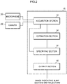
- the information processing device 10 functionally includes an acquisition section 12, an estimation section 14, an specifying section 16, and an output section 18 as illustrated in Fig. 2 .
- the acquisition section 12 acquires the sound signal output from the microphone 20 and the video output from each of the plurality of cameras 22.
- the acquisition section 12 delivers the acquired sound signal to the estimation section 14 and delivers the acquired video to the specifying section 16.
- the estimation section 14 estimates a takeoff-from-ice time and a landing-on-ice time of a jump performed by the competitor according to a silencing and a return of the ice sound based on the sound signal. For example, the estimation section 14 estimates the takeoff-from-ice time and the landing-on-ice time of the jump performed by the competitor based on a section in which a level of the sound signal is equal to or less than a predetermined threshold value. This is based on the fact that a frictional sound between the blade and the ice disappears at the time of takeoff-from-ice at the start of the jump, and the frictional sound returns at the time of landing-on-ice.
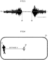
- the estimation section 14 estimates a time at which the sound signal becomes equal to or less than a threshold value TH as a takeoff-from-ice time tA.
- the estimation section 14 estimates, as a landing-on-ice time tB, the time at which the sound signal that has been equal to or less than the threshold value TH again exceeds the threshold value TH.
- the estimation section 14 may estimate the takeoff-from-ice time tA and the landing-on-ice time tB of the jump based on the sound signal from which a predetermined frequency component included in the sound signal has been removed.
- the predetermined frequency component can be, for example, a frequency component corresponding to a sound other than frictional sound between the blade and ice, such as cheers and music. As described above, in a case where the microphone 20 is installed in ice, sounds other than frictional sounds between the blade and the ice, such as cheers and music, are suppressed.
- the takeoff-from-ice time tA and the landing-on-ice time tB of the jump can be estimated with higher accuracy by removing frequency components corresponding to sounds other than frictional sounds between the blade and the ice.
- the sound signal includes a lot of cheers, music, and the like, and thus it is effective to remove a predetermined frequency component.
- the estimation section 14 delivers the estimated takeoff-from-ice time tA and landing-on-ice time tB of the jump to the specifying section 16.
- the specifying section 16 acquires a trajectory of the location of the competitor 32 on the skating rink 30 by motion tracking from the video delivered from the acquisition section 12. For example, the specifying section 16 recognizes the competitor 32 that is a target of motion tracking for each frame of the video photographed by each camera 22. For example, the specifying section 16 recognizes the competitor 32 from each frame based on characteristics such as color, shape, and the like of a wearing object worn by the competitor 32 or the competitor 32. The specifying section 16 may recognize a moving object indicated by a difference between frames as the competitor 32. Then, the specifying section 16 calculates the location of the competitor 32 recognized in each frame for each frame. Then, the specifying section 16 generates trajectory information by tracking the location of the competitor in each frame. The location of the competitor may be calculated in three dimensions or in two dimensions. In the present embodiment, a case of calculating location coordinates (x, y) of the recognized competitor 32 in a xy plane in a plan view of the skating rink 30 will be described.
- the specifying section 16 synchronizes the time information of the sound signal with the time information of the video.
- the specifying section 16 may reflect a delay time of the sound signal with respect to the video according to a distance between the competitor 32 and the microphone 20.
- the delay time is X ⁇ 3230 using the sound speed of 3230 [m/s] in ice.
- the specifying section 16 may use the delay time obtained as described above to synchronize time information obtained by subtracting the delay time from the time information of the sound signal with time information of the video.
- the specifying section 16 specifies a section from a location corresponding to the takeoff-from-ice time tA to a location corresponding to the landing-on-ice time tB as a jump section on the trajectory of the location of the competitor 32.
- each of the takeoff-from-ice time tA and the landing-on-ice time tB is time information obtained by subtracting the delay time from each of the takeoff-from-ice time tA and the landing-on-ice time tB estimated by the estimation section 14.
- the specifying section 16 specifies the location of the competitor 32 acquired from each of the frames corresponding to the time information immediately before and immediately after the takeoff-from-ice time tA in the video in which the sound signal and the time information are synchronized with each other. Then, the specifying section 16 specifies a location (hereinafter, also referred to as a "takeoff-from-ice point") corresponding to the takeoff-from-ice time tA between the specified two locations.
- a location hereinafter, also referred to as a "takeoff-from-ice point”
- the trajectory of the location of the competitor 32 is represented by a straight line corresponding to a time axis of the sound signal.
- the specifying section 16 sets a frame corresponding to time information t1 immediately before the takeoff-from-ice time tA to m1, and sets a frame corresponding to time information t2 immediately after the takeoff-from-ice time tA to m2.
- the specifying section 16 assumes that the location acquired from the frame m1 is PI, the location acquired from the frame m2 is P2, and the location of the competitor 32 changes linearly between PI and P2.
- the specifying section 16 also specifies a location (hereinafter, also referred to as a "landing-on-ice point") corresponding to the landing-on-ice time tB in the same manner as the takeoff-from-ice point.
- the specifying section 16 delivers the trajectory of the location of the competitor 32 acquired by the motion tracking and the specified locations of the takeoff-from-ice point and the landing-on-ice point to the output section 18.
- the output section 18 superimposes an image indicating the trajectory of the location of the competitor 32 on the image indicating the skating rink 30, and generates and outputs image data for displaying the specified jump section in a display mode different from other sections in the trajectory.
- the output section 18 generates image data indicating an image 38 as illustrated in Fig. 1 .
- the trajectory is indicated by a broken line
- the jump section is indicated by a solid line.
- the image 38 indicated by the output image data is displayed on, for example, a display device or the like used by a referee, and can be used for determining a rink cover or the like. It is also possible to insert the image 38 into a screen of television broadcasting or the like.
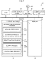
- the information processing device 10 can be realized by, for example, a computer 40 illustrated in Fig. 7 .
- the computer 40 includes a central processing unit (CPU) 41, a memory 42 as a temporary storage area, and a nonvolatile storage section 43.
- the computer 40 includes an input/output device 44 such as an input section and a display section, and a read/write (R/W) section 45 that controls reading and writing of data with respect to a storage medium 49.
- the computer 40 further includes a communication interface (I/F) 46 connected to a network such as the Internet.
- the CPU 41, the memory 42, the storage section 43, the input/output device 44, the R/W section 45, and the communication I/F 46 are connected to each other via a bus 47.
- the storage section 43 can be realized by a hard disk drive (HDD), a solid state drive (SSD), a flash memory, or the like.
- the storage section 43 as a storage medium stores an information processing program 50 for causing the computer 40 to function as the information processing device 10.
- the information processing program 50 includes an acquisition process 52, an estimation process 54, a specification process 56, and an output process 58.
- the CPU 41 reads the information processing program 50 from the storage section 43, develops the program in the memory 42, and sequentially executes the processes included in the information processing program 50.
- the CPU 41 operate as the acquisition section 12 illustrated in Fig. 2 by executing the acquisition process 52.
- the CPU 41 operates as the estimation section 14 illustrated in Fig. 2 by executing the estimation process 54.
- the CPU 41 operates as the specifying section 16 illustrated in Fig. 2 by executing the specification process 56.
- the CPU 41 operates as the output section 18 illustrated in Fig. 2 by executing the output process 58.
- the computer 40 that has executed the information processing program 50 functions as the information processing device 10.
- the CPU 41 that executes the program is hardware.
- Functions implemented by the information processing program 50 can also be implemented by, for example, a semiconductor integrated circuit, more specifically, an application specific integrated circuit (ASIC) or the like.
- a semiconductor integrated circuit more specifically, an application specific integrated circuit (ASIC) or the like.
- ASIC application specific integrated circuit
- the information processing routine is an example of an information processing method of the disclosed technology.
- Step S12 the acquisition section 12 acquires the sound signal and the video input to the information processing device 10.
- the acquisition section 12 delivers the acquired sound signal to the estimation section 14 and delivers the acquired video to the specifying section 16.
- Step S14 the estimation section 14 estimates the time when the sound signal becomes equal to or less than the threshold value TH as the takeoff-from-ice time tA, and estimates the time when the sound signal that has become equal to or less than the threshold value TH again exceeds the threshold value TH as the landing-on-ice time tB.
- the estimation section 14 delivers the estimated takeoff-from-ice time tA and landing-on-ice time tB of the jump to the specifying section 16.
- Step S16 the specifying section 16 acquires the trajectory of the location of the competitor 32 on the skating rink 30 by motion tracking from each frame of the video delivered from the acquisition section 12.
- Step S18 the specifying section 16 synchronizes the time information of the sound signal with the time information of the video. Then, the specifying section 16 specifies the location of the competitor 32 acquired from each of the frames corresponding to the time information immediately before and immediately after the takeoff-from-ice time tA in each frame of the video in which the sound signal and the time information are synchronized with each other. Then, the specifying section 16 specifies the location of the takeoff-from-ice point A corresponding to the takeoff-from-ice time tA between the specified locations.
- the specifying section 16 specifies the location of the competitor 32 acquired from each of the frames corresponding to the time information immediately before and immediately after the landing-on-ice time tB. Then, the specifying section 16 specifies the location of the landing-on-ice point B corresponding to the landing-on-ice time tB between the specified locations. A section from the specified takeoff-from-ice point A to the landing-on-ice point B is specified as the jump section. The specifying section 16 delivers the trajectory of the location of the competitor 32 acquired by the motion tracking and the specified locations of the takeoff-from-ice point and the landing-on-ice point to the output section 18.
- Step S20 the output section 18 superimposes the image indicating the trajectory of the location of the competitor 32 on the image indicating the skating rink 30, and generates and outputs image data for displaying the specified jump section in the display mode different from the image indicating the trajectory. Then, the information processing routine ends.
- the information processing device acquires the sound signal collected by the microphone provided in the venue including the skating rink and the video obtained by identifiably photographing the location of the competitor on the skating rink. Then, the information processing device estimates the takeoff-from-ice time and the landing-on-ice time of the jump performed by the competitor according to the silencing and return of the ice sound based on the sound signal. The information processing device synchronizes the time information of the sound signal with the time information of the video image, and specifies each of the location corresponding to the takeoff-from-ice time and the location corresponding to the landing-on-ice time in the trajectory of the location of the competitor on the skating rink acquired from the video by motion tracking. As a result, it is possible to specify the takeoff-from-ice point and the landing-on-ice point of a jump in figure skating without attaching a sensor or the like to the competitor.
- an information processing system 200 includes an information processing device 210, a microphone 20, a first camera 22, and a second camera 24.
- the information processing system 200 performs information processing on a sound signal output from the microphone 20 and videos output from the first camera 22 and the second camera 24, and specifies a jump section from a takeoff-from-ice point to a landing-on-ice point on a trajectory of a location of a competitor, similarly to the first embodiment.
- the information processing system 200 calculates information on the jump, such as a rotation angle of a blade at the time of landing-on-ice of the jump, using the specified the jump section.
- the first camera 22 is similar to the camera 22 in the first embodiment, and is, for example, a photographing device for motion tracking that photographs a video capable of specifying a location of a competitor 32 on a skating rink 30.
- the second camera 24 is a photographing device that identifiably photographs three-dimensional positions of a predetermined part of a wearing object worn by the competitor 32 and the competitor 32 on the skating rink 30.
- a plurality of (for example, two) second cameras 24 are installed at locations where the three-dimensional location of the predetermined part can be measured by a stereo camera system.
- Fig. 9 only one second camera 24 is illustrated.
- Each second camera 24 outputs a video photographed at a predetermined frame rate (for example, 30 fps, 60 fps, and the like).
- the output video includes a plurality of frames, and time information is associated with each frame.
- One ToF (Time-of-Flight) type camera may be used as the second camera 24.
- first camera 22 the video photographed by first camera 22
- second camera 24 the video photographed by second camera 24
- the information processing device 210 functionally includes an acquisition section 212, an estimation section 14, an specifying section 216, a calculation section 19, and an output section 218 as illustrated in Fig. 10 .
- the acquisition section 212 acquires the sound signal output from the microphone 20, the first video output from each of the plurality of first cameras 22, and the second video output from each of the plurality of second cameras 24.
- the acquisition section 212 delivers the acquired sound signal to the estimation section 14, and delivers the acquired first video and second video to the specifying section 216.
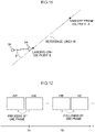
- the specifying section 216 specifies a location of each of a takeoff-from-ice point A and a landing-on-ice point B based on a takeoff-from-ice time tA and a landing-on-ice time tB estimated by the estimation section 14 and the first video. As illustrated in Fig. 11 , the specifying section 216 specifies a straight line passing through the takeoff-from-ice point A and the landing-on-ice point B as a reference line (A-B) for determining the rotation of the jump.
- A-B reference line
- the specifying section 216 delivers the trajectory of the location of the competitor 32 and the locations of the takeoff-from-ice point A and the landing-on-ice point B to the output section 218, and delivers the locations of the takeoff-from-ice point A and the landing-on-ice point B and the information of the reference line (A-B) to the calculation section 19.
- the specifying section 216 synchronizes the time information of the sound signal with the time information of the second video, and specifies a frame corresponding to the takeoff-from-ice time tA to a frame corresponding to the landing-on-ice time tB of the jump in the second video delivered from the acquisition section 212 as the jump section.
- the specifying section 216 specifies, as a start frame mS corresponding to the takeoff-from-ice time tA, a frame preceding the frame (hereinafter, referred to as a "takeoff-from-ice frame mA") of the second video of the time information synchronized with the takeoff-from-ice time tA, by a predetermined number of frames.
- the specifying section 216 specifies, as an end frame mE corresponding to the landing-on-ice time tB, a frame following the frame (hereinafter, referred to as a "landing-on-ice frame mB") of the second video of the time information synchronized with the landing-on-ice time tB, by a predetermined number of frames.
- the reason why the frames before and after the takeoff-from-ice frame mA to the landing-on-ice frame mB are included is to specify the start frame mS and the end frame mE so as to reliably include the takeoff-from-ice to the landing-on-ice.
- the predetermined number can be 1, for example.
- the specifying section 216 may use a predetermined number based on the delay time when specifying the start frame mS, and may use 1 as the predetermined number when specifying the end frame mE.
- the specifying section 216 extracts a section from the start frame mS to the end frame mE as a jump section from the second video delivered from the acquisition section 212, and delivers the section to the calculation section 19.
- the calculation section 19 three-dimensionally analyzes each of the frames of the second video included in the jump section delivered from the specifying section 216, and calculates the three-dimensional locations (x, y, z) of the predetermined part of the wearing object worn by the competitor 32 and the competitor 32.
- the predetermined part includes a distal end 34 and a terminal end 36 of a blade of a skate shoe worn by the competitor 32.
- the predetermined part may include each joint, head, and face parts such as eyes, nose, and mouth of the competitor 32.
- an existing method such as a recognition method using a shape of a predetermined part or a recognition method using a human skeleton model can be used.
- the calculation section 19 may calculate the three-dimensional location of the predetermined part using two images obtained by photographing the competitor 32 at an angle suitable for calculating the three-dimensional location among the videos photographed by each of the plurality of second cameras 24.
- the calculation section 19 calculates an absolute angle of the blade with a photographing direction of the second camera 24 as a reference using the locations of the distal end 34 and the terminal end 36 of the blade calculated from each of the frames included in the jump section. For example, the calculation section 19 can calculate an angle formed by the photographing direction of the second camera 24 or a line perpendicular to the photographing direction and a line connecting the distal end 34 and the terminal end 36 of the blade as the absolute angle of the blade.
- the calculation section 19 may determine any one of the second cameras 24 among the plurality of second cameras 24 as a main camera and calculate the absolute angle of the blade based on a photographing direction of the main second camera 24.
- the calculation section 19 converts the absolute angle of the blade into an angle (hereinafter, referred to as a "rotation angle ⁇ ") with respect to a reference line for determining insufficient rotation of the jump. Specifically, the calculation section 19 calculates the rotation angle ⁇ of the blade by subtracting the angle difference between the line with the photographing direction of the second camera 24 as a reference and the reference line (A-B) specified by the specifying section 216 from the absolute angle of the blade.
- Fig. 14 illustrates the rotation angle ⁇ calculated from each of the frames included in the jump section.
- the calculation section 19 calculates a delay time ⁇ t of the sound signal for the second video at the time of the landing-on-ice.
- the delay time is the distance X [m] ⁇ 3230 [m/s] (sound velocity in ice).
- the distance X is a distance between the location of the microphone 20 and the landing-on-ice point B.
- the calculation section 19 calculates the rotation angle of the blade at the time of the landing-on-ice based on a rotation angle ⁇ (mE) calculated from the end frame mE and a rotation angle ⁇ (mE-1) calculated from a frame mE-1 preceding the end frame mE by one frame.
- Fig. 15 is an enlarged view of a portion indicated by a broken line frame in Fig. 14 .
- the landing-on-ice time tB estimated based on the sound signal includes a corrected landing-on-ice time tB- ⁇ t in consideration of the calculated delay time ⁇ t within the time of one frame from the frame mE-1 to the frame mE.
- the delay time ⁇ t is a minute time compared to a time for one frame.
- the calculation section 19 assumes that the rotation speed during the jump is substantially constant, and linearly interpolates the rotation angle between the frame mE-1 and the frame mE using the rotation angle ⁇ (mE-1) and the rotation angle ⁇ (mE). Then, the calculation section 19 calculates a rotation angle corresponding to the corrected landing-on-ice time tB- ⁇ t as a rotation angle ⁇ (tB- ⁇ t) at the time of the landing-on-ice.
- the calculation section 19 can also calculate other information based on the three-dimensional location of the predetermined part corresponding to the jump section. For example, the calculation section 19 can calculate a location of a waist as the predetermined part, and calculate a difference between a minimum value and a maximum value of the location of the waist calculated from each frame included in the jump section as a jump height. The calculation section 19 can calculate the distance from the takeoff-from-ice point A to the landing-on-ice point B specified by the specifying section 216 as a jump distance. The calculation section 19 can calculate a rotation speed from the time from the takeoff-from-ice time tA to the landing-on-ice time tB and the change in the rotation angle in the jump section.
- the calculation section 19 can calculate a crossing speed from a time from the start frame mS to the predetermined frame and a change amount of the location of the predetermined part during that time.
- the calculation section 19 delivers the rotation angle ⁇ (tB- ⁇ t) at the time of the landing-on-ice and other calculated information to the output section 218.
- the output section 218 generates and outputs image data of an image 38 indicating the jump section on the trajectory of the location of the competitor 32.
- the output section 218 outputs information such as the rotation angle ⁇ (tB- ⁇ t) at the time of the landing-on-ice delivered from the calculation section 19.
- the rotation angle ⁇ (tB- ⁇ t) at the time of the landing-on-ice can be used for determination of insufficient rotation of the jump or the like.
- the output information can also be used as studs to be displayed on a screen of television broadcasting or the like.
- the information processing device 210 can be realized by, for example, a computer 40 illustrated in Fig. 7 .
- a storage section 43 of the computer 40 stores an information processing program 250 for causing the computer 40 to function as the information processing device 210.
- the information processing program 250 includes an acquisition process 252, an estimation process 54, a specification process 256, a calculation process 59, and an output process 258.
- a CPU 41 reads the information processing program 250 from the storage section 43, develops the program in a memory 42, and sequentially executes the processes included in the information processing program 250.
- the CPU 41 operates as the acquisition section 212 illustrated in Fig. 10 by executing the acquisition process 252.
- the CPU 41 operates as the estimation section 14 illustrated in Fig. 10 by executing the estimation process 54.
- the CPU 41 operates as the specifying section 216 illustrated in Fig. 10 by executing the specification process 256.
- the CPU 41 operates as the calculation section 19 illustrated in Fig. 10 by executing the calculation process 59.
- the CPU 41 operates as the output section 218 illustrated in Fig. 10 by executing the output process 258.
- the computer 40 that has executed the information processing program 250 functions as the information processing device 210.
- the functions implemented by the information processing program 250 can also be implemented by, for example, a semiconductor integrated circuit, more specifically, an ASIC or the like.
- the sound signal output from the microphone 20, the first video photographed by each of the plurality of first cameras 22, and the second video photographed by each of the plurality of second cameras 24 are input to the information processing device 210. Then, the information processing device 210 executes the information processing routine illustrated in Fig. 16 .
- the same step numbers are assigned to the same processes as those of the information processing routine ( Fig. 8 ) in the first embodiment, and a detailed description thereof will be omitted.
- the information processing routine is an example of an information processing method of the disclosed technology.
- Step S212 the acquisition section 212 acquires the sound signal, the first video, and the second video input to the information processing device 210.
- the acquisition section 212 delivers the acquired sound signal to the estimation section 14, and delivers the acquired first video and second video to the specifying section 216.
- the specifying section 216 specifies the straight line passing through the takeoff-from-ice point A and the landing-on-ice point B as the reference line (A-B) for determining the rotation of the jump using the location of each of the takeoff-from-ice point A and the landing-on-ice point B specified in Step S18.
- the specifying section 216 specifies, as the start frame mS corresponding to the takeoff-from-ice time tA, the frame preceding the takeoff-from-ice frame mA of the time information synchronized with the takeoff-from-ice time tA in the second video, by a predetermined number of frames (for example, one frame).
- the specifying section 216 specifies, as the end frame mE corresponding to the landing-on-ice time tB, the frame following the landing-on-ice frame mB of time information synchronized with the landing-on-ice time tB, by a predetermined number (for example, one frame).
- the specifying section 216 extracts a section from the start frame mS to the end frame mE as a jump section from the second video delivered from the acquisition section 212, and delivers the section to the calculation section 19.
- Step S222 the calculation section 19 three-dimensionally analyzes each of the frames included in the jump section delivered from the specifying section 216, and calculates a three-dimensional location (x, y, z) of a predetermined part including the distal end 34 and the terminal end 36 of the blade. Then, the calculation section 19 calculates, as the absolute angle of the blade, an angle formed by the line with the photographing direction of the second camera 24 as a reference and the line connecting the distal end 34 and the terminal end 36 of the blade. The calculation section 19 calculates the rotation angle ⁇ of the blade by subtracting the angle difference between the reference line specified by the specifying section 216 in Step S218 and the line with the photographing direction of the second camera 24 as a reference from the absolute angle of the blade.
- Step S226 the calculation section 19 calculates other information such as the jump distance and the rotation speed based on the three-dimensional location of the predetermined part corresponding to the jump section, the locations of the takeoff-from-ice point A and the landing-on-ice point B specified by the specifying section 216, and the like.
- Step S228, the output section 218 generates image data of the image 38 indicating the jump section on the trajectory of the location of the competitor 32, and outputs the image data and information such as the rotation angle ⁇ (tB- ⁇ t) at the time of the landing-on-ice calculated in Step S226. Then, the information processing routine ends.
- the information processing device estimates the takeoff-from-ice time and the landing-on-ice time from the sound signal, thereby accurately specifying the locations of the takeoff-from-ice point and the landing-on-ice point.
- the information processing device specifies a reference line for determining the rotation of the jump using the specified takeoff-from-ice point and landing-on-ice point.
- the present invention is not limited thereto.
- the program according to the disclosed technology can also be provided in a form stored in a storage medium such as a CD-ROM, a DVD-ROM, or a USB memory.
Landscapes
- Engineering & Computer Science (AREA)
- Multimedia (AREA)
- Signal Processing (AREA)
- Theoretical Computer Science (AREA)
- Computer Vision & Pattern Recognition (AREA)
- Physics & Mathematics (AREA)
- General Physics & Mathematics (AREA)
- Health & Medical Sciences (AREA)
- General Health & Medical Sciences (AREA)
- Physical Education & Sports Medicine (AREA)
- Computer Security & Cryptography (AREA)
- Image Analysis (AREA)
- Closed-Circuit Television Systems (AREA)
- User Interface Of Digital Computer (AREA)
- Studio Devices (AREA)
- Devices For Executing Special Programs (AREA)
Abstract
Description
- The disclosed technology relates to an information processing program, an information processing device, and an information processing method.
- Conventionally, a predetermined point or section such as a location and a posture of a competitor is specified from a video during a sport competition. The predetermined point is, for example, a moment of impact on a ball in golf, baseball, tennis, or the like, a moment of jumping or landing in gymnastics or the like, or the like.
- As a technology related to the specification of the predetermined point or section as described above, for example, an information processing device that specifies a decisive moment from consecutive motions of a subject and extracts the moment as an image has been proposed. The device receives sensor data from a sensor attached to a user or an object in contact with the user, and time information corresponding to the sensor data. The device specifies a time at which a predetermined motion pattern occurs in the user or the object based on the sensor data and the time information. Then, the device selects one or a plurality of images from a series of images including the user or the object photographed at predetermined time intervals according to a specified time.
- Patent Document 1: Japanese Patent Application Laid-Open (
JP-A) No. 2015-82817 - As points to be specified, locations of a takeoff-from-ice point and a landing-on-ice point of a jump of figure skating are assumed. In the figure skating, a slight change such as attaching a sensor to a competitor, or wear or shoes worn by the competitor may affect accuracy of jumping or the like. Therefore, it is difficult to specify the locations of the takeoff-from-ice point and the landing-on-ice point of the jump in the figure skating by applying the conventional technique.
- As one aspect, an object of the disclosed technology is to specify the takeoff-from-ice point and the landing-on-ice point of the jump in the figure skating.
- As one aspect, the disclosed technology acquires a sound signal collected by a microphone provided in a venue including a skating rink, and a first video obtained by photographing a competitor on the skating rink. The disclosed technology estimates a takeoff-from-ice time and a landing-on-ice time of a jump performed by the competitor according to a silencing and a return of an ice sound based on the sound signal. Then, the disclosed technology synchronizes time information of the sound signal with time information of the first video, and acquires a trajectory of the location of the competitor on the skating rink based on the first video. The disclosed technology specifies each of a location corresponding to the takeoff-from-ice time and a location corresponding to the landing-on-ice time in the trajectory of a location of the competitor.
- As one aspect, there is an effect that a takeoff-from-ice point and a landing-on-ice point of a jump in figure skating can be specified.
-
-
Fig. 1 is a block diagram illustrating a schematic configuration of an information processing system according to a first embodiment. -
Fig. 2 is a functional block of an information processing device according to the first embodiment. -
Fig. 3 is a diagram for explaining estimation of a takeoff-from-ice time and a landing-on-ice time. -
Fig. 4 is a diagram for explaining a delay time of a sound signal for a video. -
Fig. 5 is a diagram for explaining specification of a takeoff-from-ice point and a landing-on-ice point. -
Fig. 6 is a diagram for explaining specific details of the takeoff-from-ice point. -
Fig. 7 is a block diagram illustrating a schematic configuration of a computer that functions as the information processing device. -
Fig. 8 is a flowchart illustrating an example of an information processing routine according to the first embodiment. -
Fig. 9 is a block diagram illustrating a schematic configuration of an information processing system according to a second embodiment. -
Fig. 10 is a functional block of an information processing device according to the second embodiment. -
Fig. 11 is a diagram for explaining specification of a reference line. -
Fig. 12 is a diagram for explaining specification of a frame of a second video indicating a jump section. -
Fig. 13 is a diagram for explaining calculation of locations of a distal end and a terminal end of a blade as a predetermined part. -
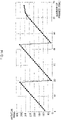
Fig. 14 is a diagram illustrating a rotation angle θ calculated from each of frames included in a jump section. -
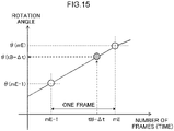
Fig. 15 is an enlarged view of a portion indicated by a broken-line frame inFig. 14 . -
Fig. 16 is a flowchart illustrating an example of an information processing routine according to the second embodiment. - Hereinafter, an example of an embodiment according to the disclosed technology will be described with reference to the drawings.
- First, an outline of an information processing system according to the first embodiment will be described. As illustrated in
Fig. 1 , aninformation processing system 100 includes aninformation processing device 10, amicrophone 20, and acamera 22. Theinformation processing system 100 performs information processing on a sound signal output from themicrophone 20 and a video output from thecamera 22, and specifies a jump section from a takeoff-from-ice point to a landing-on-ice point on a trajectory of a location of a competitor. - The microphone 20 is installed in ice of a
skating rink 30. For example, at the time of setting up theskating rink 30, themicrophone 20 can be installed in the ice by being embedded in theskating rink 30 when ice is spread. Themicrophone 20 collects a voice in a competition venue and outputs a sound signal. Since themicrophone 20 is installed in the ice, a sound component indicating cheer, music, or the like is suppressed, and a sound component indicating a frictional sound between a surface (ice) of theskating rink 30 and a blade of a skate shoe becomes dominant in a sound component included in the sound signal collected by themicrophone 20. Time information is associated with each sampling point of the sound signal to be output. The frictional sound between the surface (ice) of theskating rink 30 and the blade of the skate shoe is an example of an ice sound. - The
camera 22 is, for example, a photographing device for motion tracking that photographs a video capable of specifying the location of thecompetitor 32 on theskating rink 30. For example, a plurality of (For example, three)cameras 22 is installed on a ceiling, a side wall, or the like of a venue. InFig. 1 , only onecamera 22 is illustrated. Eachcamera 22 outputs a video photographed at a predetermined frame rate (For example, 120 fps). The output video includes a plurality of frames, and time information is associated with each frame. - The
information processing device 10 functionally includes anacquisition section 12, anestimation section 14, anspecifying section 16, and anoutput section 18 as illustrated inFig. 2 . - The
acquisition section 12 acquires the sound signal output from themicrophone 20 and the video output from each of the plurality ofcameras 22. Theacquisition section 12 delivers the acquired sound signal to theestimation section 14 and delivers the acquired video to the specifyingsection 16. - The
estimation section 14 estimates a takeoff-from-ice time and a landing-on-ice time of a jump performed by the competitor according to a silencing and a return of the ice sound based on the sound signal. For example, theestimation section 14 estimates the takeoff-from-ice time and the landing-on-ice time of the jump performed by the competitor based on a section in which a level of the sound signal is equal to or less than a predetermined threshold value. This is based on the fact that a frictional sound between the blade and the ice disappears at the time of takeoff-from-ice at the start of the jump, and the frictional sound returns at the time of landing-on-ice. As the threshold value, a value that can be generally regarded as the silencing of the sound signal may be determined. Specifically, as illustrated inFig. 3 , theestimation section 14 estimates a time at which the sound signal becomes equal to or less than a threshold value TH as a takeoff-from-ice time tA. Theestimation section 14 estimates, as a landing-on-ice time tB, the time at which the sound signal that has been equal to or less than the threshold value TH again exceeds the threshold value TH. - The
estimation section 14 may estimate the takeoff-from-ice time tA and the landing-on-ice time tB of the jump based on the sound signal from which a predetermined frequency component included in the sound signal has been removed. The predetermined frequency component can be, for example, a frequency component corresponding to a sound other than frictional sound between the blade and ice, such as cheers and music. As described above, in a case where themicrophone 20 is installed in ice, sounds other than frictional sounds between the blade and the ice, such as cheers and music, are suppressed. However, the takeoff-from-ice time tA and the landing-on-ice time tB of the jump can be estimated with higher accuracy by removing frequency components corresponding to sounds other than frictional sounds between the blade and the ice. In a case where themicrophone 20 is installed in a venue that is not in ice, the sound signal includes a lot of cheers, music, and the like, and thus it is effective to remove a predetermined frequency component. Theestimation section 14 delivers the estimated takeoff-from-ice time tA and landing-on-ice time tB of the jump to the specifyingsection 16. - The specifying
section 16 acquires a trajectory of the location of thecompetitor 32 on theskating rink 30 by motion tracking from the video delivered from theacquisition section 12. For example, the specifyingsection 16 recognizes thecompetitor 32 that is a target of motion tracking for each frame of the video photographed by eachcamera 22. For example, the specifyingsection 16 recognizes thecompetitor 32 from each frame based on characteristics such as color, shape, and the like of a wearing object worn by thecompetitor 32 or thecompetitor 32. The specifyingsection 16 may recognize a moving object indicated by a difference between frames as thecompetitor 32. Then, the specifyingsection 16 calculates the location of thecompetitor 32 recognized in each frame for each frame. Then, the specifyingsection 16 generates trajectory information by tracking the location of the competitor in each frame. The location of the competitor may be calculated in three dimensions or in two dimensions. In the present embodiment, a case of calculating location coordinates (x, y) of the recognizedcompetitor 32 in a xy plane in a plan view of theskating rink 30 will be described. - The specifying
section 16 synchronizes the time information of the sound signal with the time information of the video. At this time, the specifyingsection 16 may reflect a delay time of the sound signal with respect to the video according to a distance between thecompetitor 32 and themicrophone 20. Specifically, as illustrated inFig. 4 , in a case where the distance between thecompetitor 32 and themicrophone 20 is X [m], the delay time is X ÷ 3230 using the sound speed of 3230 [m/s] in ice. For example, the specifyingsection 16 can obtain a maximum value of a distance from the location of themicrophone 20 to an end of theskating rink 30 as X = 30 m and the delay time as 30 ÷ 3230 = 9.28 [ms]. The specifyingsection 16 may use the delay time obtained as described above to synchronize time information obtained by subtracting the delay time from the time information of the sound signal with time information of the video. - The specifying
section 16 specifies a section from a location corresponding to the takeoff-from-ice time tA to a location corresponding to the landing-on-ice time tB as a jump section on the trajectory of the location of thecompetitor 32. As described above, when the delay time of the sound signal is reflected, each of the takeoff-from-ice time tA and the landing-on-ice time tB is time information obtained by subtracting the delay time from each of the takeoff-from-ice time tA and the landing-on-ice time tB estimated by theestimation section 14. - Specifically, as illustrated in
Fig. 5 , the specifyingsection 16 specifies the location of thecompetitor 32 acquired from each of the frames corresponding to the time information immediately before and immediately after the takeoff-from-ice time tA in the video in which the sound signal and the time information are synchronized with each other. Then, the specifyingsection 16 specifies a location (hereinafter, also referred to as a "takeoff-from-ice point") corresponding to the takeoff-from-ice time tA between the specified two locations. InFig. 5 , for convenience of explanation, the trajectory of the location of thecompetitor 32 is represented by a straight line corresponding to a time axis of the sound signal. - More specifically, as illustrated in
Fig. 6 , the specifyingsection 16 sets a frame corresponding to time information t1 immediately before the takeoff-from-ice time tA to m1, and sets a frame corresponding to time information t2 immediately after the takeoff-from-ice time tA to m2. The specifyingsection 16 assumes that the location acquired from the frame m1 is PI, the location acquired from the frame m2 is P2, and the location of thecompetitor 32 changes linearly between PI and P2. In this case, the specifyingsection 16 specifies a location between PI and P2 and corresponding to a ratio of tA to a time (t2-t1) for one frame as the takeoff-from-ice point A. That is, the specifyingsection 16 can specify the takeoff-from-ice point by A= PI + (P2 - PI) × (tA - t1)/(t2 - t1). - The specifying
section 16 also specifies a location (hereinafter, also referred to as a "landing-on-ice point") corresponding to the landing-on-ice time tB in the same manner as the takeoff-from-ice point. The specifyingsection 16 delivers the trajectory of the location of thecompetitor 32 acquired by the motion tracking and the specified locations of the takeoff-from-ice point and the landing-on-ice point to theoutput section 18. - The
output section 18 superimposes an image indicating the trajectory of the location of thecompetitor 32 on the image indicating theskating rink 30, and generates and outputs image data for displaying the specified jump section in a display mode different from other sections in the trajectory. For example, theoutput section 18 generates image data indicating animage 38 as illustrated inFig. 1 . In the example of theimage 38 ofFig. 1 , the trajectory is indicated by a broken line, and the jump section is indicated by a solid line. Theimage 38 indicated by the output image data is displayed on, for example, a display device or the like used by a referee, and can be used for determining a rink cover or the like. It is also possible to insert theimage 38 into a screen of television broadcasting or the like. - The
information processing device 10 can be realized by, for example, acomputer 40 illustrated inFig. 7 . Thecomputer 40 includes a central processing unit (CPU) 41, amemory 42 as a temporary storage area, and anonvolatile storage section 43. Thecomputer 40 includes an input/output device 44 such as an input section and a display section, and a read/write (R/W)section 45 that controls reading and writing of data with respect to astorage medium 49. Thecomputer 40 further includes a communication interface (I/F) 46 connected to a network such as the Internet. TheCPU 41, thememory 42, thestorage section 43, the input/output device 44, the R/W section 45, and the communication I/F 46 are connected to each other via abus 47. - The
storage section 43 can be realized by a hard disk drive (HDD), a solid state drive (SSD), a flash memory, or the like. Thestorage section 43 as a storage medium stores aninformation processing program 50 for causing thecomputer 40 to function as theinformation processing device 10. Theinformation processing program 50 includes anacquisition process 52, an estimation process 54, aspecification process 56, and anoutput process 58. - The
CPU 41 reads theinformation processing program 50 from thestorage section 43, develops the program in thememory 42, and sequentially executes the processes included in theinformation processing program 50. TheCPU 41 operate as theacquisition section 12 illustrated inFig. 2 by executing theacquisition process 52. TheCPU 41 operates as theestimation section 14 illustrated inFig. 2 by executing the estimation process 54. TheCPU 41 operates as the specifyingsection 16 illustrated inFig. 2 by executing thespecification process 56. TheCPU 41 operates as theoutput section 18 illustrated inFig. 2 by executing theoutput process 58. As a result, thecomputer 40 that has executed theinformation processing program 50 functions as theinformation processing device 10. TheCPU 41 that executes the program is hardware. - Functions implemented by the
information processing program 50 can also be implemented by, for example, a semiconductor integrated circuit, more specifically, an application specific integrated circuit (ASIC) or the like. - Next, an operation of the
information processing system 100 according to the first embodiment will be described. When the sound signal output from themicrophone 20 and the video photographed by each of the plurality ofcameras 22 are input to theinformation processing device 10, an information processing routine illustrated inFig. 8 is executed in theinformation processing device 10. The information processing routine is an example of an information processing method of the disclosed technology. - In Step S12, the
acquisition section 12 acquires the sound signal and the video input to theinformation processing device 10. Theacquisition section 12 delivers the acquired sound signal to theestimation section 14 and delivers the acquired video to the specifyingsection 16. - Next, in Step S14, the
estimation section 14 estimates the time when the sound signal becomes equal to or less than the threshold value TH as the takeoff-from-ice time tA, and estimates the time when the sound signal that has become equal to or less than the threshold value TH again exceeds the threshold value TH as the landing-on-ice time tB. Theestimation section 14 delivers the estimated takeoff-from-ice time tA and landing-on-ice time tB of the jump to the specifyingsection 16. - Next, in Step S16, the specifying
section 16 acquires the trajectory of the location of thecompetitor 32 on theskating rink 30 by motion tracking from each frame of the video delivered from theacquisition section 12. - Next, in Step S18, the specifying
section 16 synchronizes the time information of the sound signal with the time information of the video. Then, the specifyingsection 16 specifies the location of thecompetitor 32 acquired from each of the frames corresponding to the time information immediately before and immediately after the takeoff-from-ice time tA in each frame of the video in which the sound signal and the time information are synchronized with each other. Then, the specifyingsection 16 specifies the location of the takeoff-from-ice point A corresponding to the takeoff-from-ice time tA between the specified locations. Similarly, in each frame of the video in which the sound signal and the time information are synchronized with each other, the specifyingsection 16 specifies the location of thecompetitor 32 acquired from each of the frames corresponding to the time information immediately before and immediately after the landing-on-ice time tB. Then, the specifyingsection 16 specifies the location of the landing-on-ice point B corresponding to the landing-on-ice time tB between the specified locations. A section from the specified takeoff-from-ice point A to the landing-on-ice point B is specified as the jump section. The specifyingsection 16 delivers the trajectory of the location of thecompetitor 32 acquired by the motion tracking and the specified locations of the takeoff-from-ice point and the landing-on-ice point to theoutput section 18. - Next, in Step S20, the
output section 18 superimposes the image indicating the trajectory of the location of thecompetitor 32 on the image indicating theskating rink 30, and generates and outputs image data for displaying the specified jump section in the display mode different from the image indicating the trajectory. Then, the information processing routine ends. - As described above, according to the information processing system according to the first embodiment, the information processing device acquires the sound signal collected by the microphone provided in the venue including the skating rink and the video obtained by identifiably photographing the location of the competitor on the skating rink. Then, the information processing device estimates the takeoff-from-ice time and the landing-on-ice time of the jump performed by the competitor according to the silencing and return of the ice sound based on the sound signal. The information processing device synchronizes the time information of the sound signal with the time information of the video image, and specifies each of the location corresponding to the takeoff-from-ice time and the location corresponding to the landing-on-ice time in the trajectory of the location of the competitor on the skating rink acquired from the video by motion tracking. As a result, it is possible to specify the takeoff-from-ice point and the landing-on-ice point of a jump in figure skating without attaching a sensor or the like to the competitor.
- By estimating the takeoff-from-ice time and the landing-on-ice time from the sound signal, it is possible to specify the location at a time finer than the time in the time unit of one frame as compared with the case of specifying the location from the video by motion tracking.
- Next, a second embodiment will be described. In an information processing system according to the second embodiment, the same components as those of the
information processing system 100 according to the first embodiment are denoted by the same reference numerals, and detailed description thereof will be omitted. - As illustrated in
Fig. 9 , aninformation processing system 200 according to the second embodiment includes aninformation processing device 210, amicrophone 20, afirst camera 22, and asecond camera 24. Theinformation processing system 200 performs information processing on a sound signal output from themicrophone 20 and videos output from thefirst camera 22 and thesecond camera 24, and specifies a jump section from a takeoff-from-ice point to a landing-on-ice point on a trajectory of a location of a competitor, similarly to the first embodiment. In addition, theinformation processing system 200 calculates information on the jump, such as a rotation angle of a blade at the time of landing-on-ice of the jump, using the specified the jump section. - The
first camera 22 is similar to thecamera 22 in the first embodiment, and is, for example, a photographing device for motion tracking that photographs a video capable of specifying a location of acompetitor 32 on askating rink 30. - The
second camera 24 is a photographing device that identifiably photographs three-dimensional positions of a predetermined part of a wearing object worn by thecompetitor 32 and thecompetitor 32 on theskating rink 30. A plurality of (for example, two)second cameras 24 are installed at locations where the three-dimensional location of the predetermined part can be measured by a stereo camera system. InFig. 9 , only onesecond camera 24 is illustrated. Eachsecond camera 24 outputs a video photographed at a predetermined frame rate (for example, 30 fps, 60 fps, and the like). The output video includes a plurality of frames, and time information is associated with each frame. One ToF (Time-of-Flight) type camera may be used as thesecond camera 24. - Hereinafter, the video photographed by
first camera 22 is referred to as a first video, and the video photographed bysecond camera 24 is referred to as a second video. - The
information processing device 210 functionally includes anacquisition section 212, anestimation section 14, an specifyingsection 216, acalculation section 19, and anoutput section 218 as illustrated inFig. 10 . - The
acquisition section 212 acquires the sound signal output from themicrophone 20, the first video output from each of the plurality offirst cameras 22, and the second video output from each of the plurality ofsecond cameras 24. Theacquisition section 212 delivers the acquired sound signal to theestimation section 14, and delivers the acquired first video and second video to the specifyingsection 216. - Similarly to the specifying
section 16 in the first embodiment, the specifyingsection 216 specifies a location of each of a takeoff-from-ice point A and a landing-on-ice point B based on a takeoff-from-ice time tA and a landing-on-ice time tB estimated by theestimation section 14 and the first video. As illustrated inFig. 11 , the specifyingsection 216 specifies a straight line passing through the takeoff-from-ice point A and the landing-on-ice point B as a reference line (A-B) for determining the rotation of the jump. The specifyingsection 216 delivers the trajectory of the location of thecompetitor 32 and the locations of the takeoff-from-ice point A and the landing-on-ice point B to theoutput section 218, and delivers the locations of the takeoff-from-ice point A and the landing-on-ice point B and the information of the reference line (A-B) to thecalculation section 19. - The specifying
section 216 synchronizes the time information of the sound signal with the time information of the second video, and specifies a frame corresponding to the takeoff-from-ice time tA to a frame corresponding to the landing-on-ice time tB of the jump in the second video delivered from theacquisition section 212 as the jump section. - Specifically, as illustrated in
Fig. 12 , the specifyingsection 216 specifies, as a start frame mS corresponding to the takeoff-from-ice time tA, a frame preceding the frame (hereinafter, referred to as a "takeoff-from-ice frame mA") of the second video of the time information synchronized with the takeoff-from-ice time tA, by a predetermined number of frames. The specifyingsection 216 specifies, as an end frame mE corresponding to the landing-on-ice time tB, a frame following the frame (hereinafter, referred to as a "landing-on-ice frame mB") of the second video of the time information synchronized with the landing-on-ice time tB, by a predetermined number of frames. The reason why the frames before and after the takeoff-from-ice frame mA to the landing-on-ice frame mB are included is to specify the start frame mS and the end frame mE so as to reliably include the takeoff-from-ice to the landing-on-ice. As illustrated inFig. 12 , the predetermined number can be 1, for example. - The specifying
section 216 may set the predetermined number as the number obtained by converting a delay time of the sound signal for the video described above into the number of frames. For example, in a case where a distance X [m] between thecompetitor 32 and themicrophone 20 is X = 30 m, the delay time is 30 ÷ 3230 = 9.28 [ms]. In a case where a frame rate of the second video is 30 fps or 60 fps, similarly to the example ofFig. 12 , the predetermined number may be 1, and in a case where the frame rate of the second video is 120 fps, the predetermined number may be 2. - The specifying
section 216 may use a predetermined number based on the delay time when specifying the start frame mS, and may use 1 as the predetermined number when specifying the end frame mE. - The specifying
section 216 extracts a section from the start frame mS to the end frame mE as a jump section from the second video delivered from theacquisition section 212, and delivers the section to thecalculation section 19. - The
calculation section 19 three-dimensionally analyzes each of the frames of the second video included in the jump section delivered from the specifyingsection 216, and calculates the three-dimensional locations (x, y, z) of the predetermined part of the wearing object worn by thecompetitor 32 and thecompetitor 32. As illustrated inFig. 13 , the predetermined part includes adistal end 34 and aterminal end 36 of a blade of a skate shoe worn by thecompetitor 32. The predetermined part may include each joint, head, and face parts such as eyes, nose, and mouth of thecompetitor 32. As a method of recognizing these predetermined parts from each frame, an existing method such as a recognition method using a shape of a predetermined part or a recognition method using a human skeleton model can be used. - It is assumed that the
information processing system 200 includes three or moresecond cameras 24. In this case, thecalculation section 19 may calculate the three-dimensional location of the predetermined part using two images obtained by photographing thecompetitor 32 at an angle suitable for calculating the three-dimensional location among the videos photographed by each of the plurality ofsecond cameras 24. - The
calculation section 19 calculates an absolute angle of the blade with a photographing direction of thesecond camera 24 as a reference using the locations of thedistal end 34 and theterminal end 36 of the blade calculated from each of the frames included in the jump section. For example, thecalculation section 19 can calculate an angle formed by the photographing direction of thesecond camera 24 or a line perpendicular to the photographing direction and a line connecting thedistal end 34 and theterminal end 36 of the blade as the absolute angle of the blade. Thecalculation section 19 may determine any one of thesecond cameras 24 among the plurality ofsecond cameras 24 as a main camera and calculate the absolute angle of the blade based on a photographing direction of the mainsecond camera 24. - The
calculation section 19 converts the absolute angle of the blade into an angle (hereinafter, referred to as a "rotation angle θ") with respect to a reference line for determining insufficient rotation of the jump. Specifically, thecalculation section 19 calculates the rotation angle θ of the blade by subtracting the angle difference between the line with the photographing direction of thesecond camera 24 as a reference and the reference line (A-B) specified by the specifyingsection 216 from the absolute angle of the blade.Fig. 14 illustrates the rotation angle θ calculated from each of the frames included in the jump section. - The
calculation section 19 calculates a delay time Δt of the sound signal for the second video at the time of the landing-on-ice. As described above, the delay time is the distance X [m] ÷ 3230 [m/s] (sound velocity in ice). Here, the distance X is a distance between the location of themicrophone 20 and the landing-on-ice point B. - The
calculation section 19 calculates the rotation angle of the blade at the time of the landing-on-ice based on a rotation angle θ(mE) calculated from the end frame mE and a rotation angle θ(mE-1) calculated from a frame mE-1 preceding the end frame mE by one frame. - A specific description will be given with reference to
Fig. 15. Fig. 15 is an enlarged view of a portion indicated by a broken line frame inFig. 14 . The landing-on-ice time tB estimated based on the sound signal includes a corrected landing-on-ice time tB-Δt in consideration of the calculated delay time Δt within the time of one frame from the frame mE-1 to the frame mE. Here, the delay time Δt is a minute time compared to a time for one frame. Thecalculation section 19 assumes that the rotation speed during the jump is substantially constant, and linearly interpolates the rotation angle between the frame mE-1 and the frame mE using the rotation angle θ(mE-1) and the rotation angle θ(mE). Then, thecalculation section 19 calculates a rotation angle corresponding to the corrected landing-on-ice time tB-Δt as a rotation angle θ(tB-Δt) at the time of the landing-on-ice. - The
calculation section 19 can also calculate other information based on the three-dimensional location of the predetermined part corresponding to the jump section. For example, thecalculation section 19 can calculate a location of a waist as the predetermined part, and calculate a difference between a minimum value and a maximum value of the location of the waist calculated from each frame included in the jump section as a jump height. Thecalculation section 19 can calculate the distance from the takeoff-from-ice point A to the landing-on-ice point B specified by the specifyingsection 216 as a jump distance. Thecalculation section 19 can calculate a rotation speed from the time from the takeoff-from-ice time tA to the landing-on-ice time tB and the change in the rotation angle in the jump section. Thecalculation section 19 can calculate a crossing speed from a time from the start frame mS to the predetermined frame and a change amount of the location of the predetermined part during that time. Thecalculation section 19 delivers the rotation angle θ(tB-Δt) at the time of the landing-on-ice and other calculated information to theoutput section 218. - Similarly to the
output section 18 in the first embodiment, theoutput section 218 generates and outputs image data of animage 38 indicating the jump section on the trajectory of the location of thecompetitor 32. Theoutput section 218 outputs information such as the rotation angle θ(tB-Δt) at the time of the landing-on-ice delivered from thecalculation section 19. The rotation angle θ(tB-Δt) at the time of the landing-on-ice can be used for determination of insufficient rotation of the jump or the like. The output information can also be used as studs to be displayed on a screen of television broadcasting or the like. - The
information processing device 210 can be realized by, for example, acomputer 40 illustrated inFig. 7 . Astorage section 43 of thecomputer 40 stores aninformation processing program 250 for causing thecomputer 40 to function as theinformation processing device 210. Theinformation processing program 250 includes anacquisition process 252, an estimation process 54, aspecification process 256, acalculation process 59, and anoutput process 258. - A
CPU 41 reads theinformation processing program 250 from thestorage section 43, develops the program in amemory 42, and sequentially executes the processes included in theinformation processing program 250. TheCPU 41 operates as theacquisition section 212 illustrated inFig. 10 by executing theacquisition process 252. TheCPU 41 operates as theestimation section 14 illustrated inFig. 10 by executing the estimation process 54. TheCPU 41 operates as the specifyingsection 216 illustrated inFig. 10 by executing thespecification process 256. TheCPU 41 operates as thecalculation section 19 illustrated inFig. 10 by executing thecalculation process 59. TheCPU 41 operates as theoutput section 218 illustrated inFig. 10 by executing theoutput process 258. As a result, thecomputer 40 that has executed theinformation processing program 250 functions as theinformation processing device 210. - The functions implemented by the
information processing program 250 can also be implemented by, for example, a semiconductor integrated circuit, more specifically, an ASIC or the like. - Next, an operation of the
information processing system 200 according to the second embodiment will be described. The sound signal output from themicrophone 20, the first video photographed by each of the plurality offirst cameras 22, and the second video photographed by each of the plurality ofsecond cameras 24 are input to theinformation processing device 210. Then, theinformation processing device 210 executes the information processing routine illustrated inFig. 16 . In the information processing routine illustrated inFig. 16 , the same step numbers are assigned to the same processes as those of the information processing routine (Fig. 8 ) in the first embodiment, and a detailed description thereof will be omitted. The information processing routine is an example of an information processing method of the disclosed technology. - In Step S212, the
acquisition section 212 acquires the sound signal, the first video, and the second video input to theinformation processing device 210. Theacquisition section 212 delivers the acquired sound signal to theestimation section 14, and delivers the acquired first video and second video to the specifyingsection 216. - Through Steps S14 to S18, in the next Step S218, the specifying
section 216 specifies the straight line passing through the takeoff-from-ice point A and the landing-on-ice point B as the reference line (A-B) for determining the rotation of the jump using the location of each of the takeoff-from-ice point A and the landing-on-ice point B specified in Step S18. - Next, in Step S220, the specifying
section 216 specifies, as the start frame mS corresponding to the takeoff-from-ice time tA, the frame preceding the takeoff-from-ice frame mA of the time information synchronized with the takeoff-from-ice time tA in the second video, by a predetermined number of frames (for example, one frame). The specifyingsection 216 specifies, as the end frame mE corresponding to the landing-on-ice time tB, the frame following the landing-on-ice frame mB of time information synchronized with the landing-on-ice time tB, by a predetermined number (for example, one frame). The specifyingsection 216 extracts a section from the start frame mS to the end frame mE as a jump section from the second video delivered from theacquisition section 212, and delivers the section to thecalculation section 19. - Next, in Step S222, the
calculation section 19 three-dimensionally analyzes each of the frames included in the jump section delivered from the specifyingsection 216, and calculates a three-dimensional location (x, y, z) of a predetermined part including thedistal end 34 and theterminal end 36 of the blade. Then, thecalculation section 19 calculates, as the absolute angle of the blade, an angle formed by the line with the photographing direction of thesecond camera 24 as a reference and the line connecting thedistal end 34 and theterminal end 36 of the blade. Thecalculation section 19 calculates the rotation angle θ of the blade by subtracting the angle difference between the reference line specified by the specifyingsection 216 in Step S218 and the line with the photographing direction of thesecond camera 24 as a reference from the absolute angle of the blade. - Next, in Step S224, the
calculation section 19 calculates the distance X between the location of themicrophone 20 and the landing-on-ice point B, and calculates the delay time Δt of the sound signal with respect to the video at the time of the landing-on-ice as Δt = distance X [m] ÷ 3230 [m/s] (sound velocity in ice). Then, thecalculation section 19 linearly interpolates the rotation angle between the frame mE-1 and the frame mE using the rotation angles θ(mE-1) and θ(mE), and calculates the rotation angle corresponding to the corrected landing-on-ice time tB-Δt as the rotation angle θ(tB-Δt) at the time of the landing-on-ice. - Next, in Step S226, the
calculation section 19 calculates other information such as the jump distance and the rotation speed based on the three-dimensional location of the predetermined part corresponding to the jump section, the locations of the takeoff-from-ice point A and the landing-on-ice point B specified by the specifyingsection 216, and the like. - Next, in Step S228, the
output section 218 generates image data of theimage 38 indicating the jump section on the trajectory of the location of thecompetitor 32, and outputs the image data and information such as the rotation angle θ(tB-Δt) at the time of the landing-on-ice calculated in Step S226. Then, the information processing routine ends. - As described above, according to the information processing system according to the second embodiment, similarly to the information processing device according to the first embodiment, the information processing device estimates the takeoff-from-ice time and the landing-on-ice time from the sound signal, thereby accurately specifying the locations of the takeoff-from-ice point and the landing-on-ice point. The information processing device specifies a reference line for determining the rotation of the jump using the specified takeoff-from-ice point and landing-on-ice point. As a result, it is possible to support the determination of insufficient rotation of the jump or the like with high accuracy.
- In each of the above embodiments, the aspect in which the information processing program is stored (installed) in the storage section in advance has been described, but the present invention is not limited thereto. The program according to the disclosed technology can also be provided in a form stored in a storage medium such as a CD-ROM, a DVD-ROM, or a USB memory.
-
- 10, 210
- information processing device
- 12, 212
- acquisition section
- 14
- estimation section
- 16, 216
- specifying section
- 18, 218
- output section
- 19
- calculation section
- 20
- microphone
- 22
- camera, first camera
- 24
- second camera
- 30
- skating rink
- 32
- competitor
- 34
- distal end of blade
- 36
- terminal end of blade
- 38
- image
- 40
- computer
- 41
- CPU
- 42
- memory
- 43
- storage section
- 49
- storage medium
- 50, 250
- information processing program
- 100, 200
- information processing system
Claims (20)
- An information processing program for causing a computer to execute processing, the processing comprising:acquiring a sound signal collected by a microphone provided in a venue including a skating rink and a first video obtained by photographing a competitor on the skating rink;estimating a takeoff-from-ice time and a landing-on-ice time of a jump performed by the competitor according to a silencing and a return of an ice sound based on the sound signal; andsynchronizing time information of the sound signal with time information of the first video, and specifying each of a location corresponding to the takeoff-from-ice time and a location corresponding to the landing-on-ice time in a trajectory of a location of the competitor on the skating rink based on the first video.
- The information processing program according to claim 1, wherein:the location of the competitor in the trajectory is acquired corresponding to each of frames included in the first video,the location corresponding to the takeoff-from-ice time is specified between a location acquired from a frame corresponding to time information immediately before the takeoff-from-ice time and a location acquired from a frame corresponding to time information immediately after the takeoff-from-ice time, andthe location corresponding to the landing-on-ice time is specified between a location acquired from a frame corresponding to time information immediately before the landing-on-ice time and a location acquired from a frame corresponding to time information immediately after the landing-on-ice time.
- The information processing program according to claim 1 or 2, wherein:
when the time information of the sound signal and the time information of the first video are synchronized with each other, a delay time of the sound signal with respect to the first video is reflected. - The information processing program according to any one of claims 1 to 3, the processing further comprising:
superimposing an image indicating the trajectory of the location of the competitor on an image indicating the skating rink, and outputting image data for displaying a specified jump section in a display mode that is different from other sections in the trajectory. - The information processing program according to any one of claims 1 to 4, the processing further comprising:
specifying a straight line passing through the location corresponding to the takeoff-from-ice time and the location corresponding to the landing-on-ice time as a reference line for determining rotation of the jump. - The information processing program according to claim 5, the processing further comprising:acquiring a second video obtained by identifiably photographing three-dimensional locations of a predetermined part of a wearing object worn by the competitor and the competitor on the skating rink; andsynchronizing the time information of the sound signal with time information of the second video and calculating an angle of the predetermined part with respect to the reference line based on a three-dimensional location of the predetermined part acquired by three-dimensional image analysis from each of frames corresponding to a jump section included in the second video.
- The information processing program according to claim 6, wherein:
the predetermined part is a part specifying a direction of a blade of a skate shoe worn by the competitor. - The information processing program according to any one of claims 1 to 7, wherein:
the microphone is provided in ice of the skating rink. - The information processing program according to any one of claims 1 to 8, wherein:
the takeoff-from-ice time and the landing-on-ice time are estimated based on a sound signal from which a predetermined frequency component included in the sound signal has been removed. - An information processing device, comprising:an acquisition section configured to acquire a sound signal collected by a microphone provided in a venue including a skating rink and a first video obtained by photographing a competitor on the skating rink;an estimation section configured to estimate a takeoff-from-ice time and a landing-on-ice time of a jump performed by the competitor according to a silencing and a return of an ice sound based on the sound signal; anda specifying section configured to synchronize time information of the sound signal with time information of the first video and specify each of a location corresponding to the takeoff-from-ice time and a location corresponding to the landing-on-ice time in a trajectory of a location of the competitor on the skating rink based on the first video.
- The information processing device according to claim 10, wherein:
the specifying sectionacquires the location of the competitor in the trajectory corresponding to each of frames included in the first video,specifies the location corresponding to the takeoff-from-ice time between a location acquired from a frame corresponding to time information immediately before the takeoff-from-ice time and a location acquired from a frame corresponding to time information immediately after the takeoff-from-ice time, andspecifies the location corresponding to the landing-on-ice time between a location acquired from a frame corresponding to time information immediately before the landing-on-ice time and a location acquired from a frame corresponding to time information immediately after the landing-on-ice time. - The information processing device according to claim 10 or 11, wherein:
when the time information of the sound signal and the time information of the first video are synchronized with each other, the specifying section reflects a delay time of the sound signal with respect to the first video. - The information processing device according to any one of claims 10 to 12, further comprising:
an output section configured to superimpose an image indicating the trajectory of the location of the competitor on an image indicating the skating rink, and output image data for displaying a specified jump section in a display mode that is different from other sections in the trajectory. - The information processing device according to any one of claims 10 to 13, wherein:
the specifying section further specifies a straight line passing through the location corresponding to the takeoff-from-ice time and the location corresponding to the landing-on-ice time as a reference line for determining rotation of the jump. - The information processing device according to claim 14, wherein:the acquisition section acquires a second video obtained by identifiably photographing three-dimensional locations of a predetermined part of a wearing object worn by the competitor and the competitor on the skating rink, andthe information processing device further includes a calculation section configured to synchronize the time information of the sound signal with time information of the second video and calculate an angle of the predetermined part with respect to the reference line based on a three-dimensional location of the predetermined part acquired by three-dimensional image analysis from each of frames corresponding to a jump section included in the second video.
- The information processing device according to claim 15, wherein:
the predetermined part is a part specifying a direction of a blade of a skate shoe worn by the competitor. - The information processing device according to any one of claims 10 to 16, wherein:
the microphone is provided in ice of the skating rink. - The information processing device according to any one of claims 10 to 17, wherein:
the estimation section estimates the takeoff-from-ice time and the landing-on-ice time based on a sound signal from which a predetermined frequency component included in the sound signal has been removed. - An information processing method for causing a computer to execute processing, the processing comprising:acquiring a sound signal collected by a microphone provided in a venue including a skating rink and a first video obtained by photographing a competitor on the skating rink;estimating a takeoff-from-ice time and a landing-on-ice time of a jump performed by the competitor according to a silencing and a return of an ice sound based on the sound signal; andsynchronizing time information of the sound signal with time information of the first video, and specifying each of a location corresponding to the takeoff-from-ice time and a location corresponding to the landing-on-ice time in a trajectory of a location of the competitor on the skating rink based on the first video.
- A storage medium storing an information processing program for causing a computer to execute processing, the processing comprising:acquiring a sound signal collected by a microphone provided in a venue including a skating rink and a first video obtained by photographing a competitor on the skating rink;estimating a takeoff-from-ice time and a landing-on-ice time of a jump performed by the competitor according to a silencing and a return of an ice sound based on the sound signal; andsynchronizing time information of the sound signal with time information of the first video, and specifying each of a location corresponding to the takeoff-from-ice time and a location corresponding to the landing-on-ice time in a trajectory of a location of the competitor on the skating rink based on the first video.
Applications Claiming Priority (1)
| Application Number | Priority Date | Filing Date | Title |
|---|---|---|---|
| PCT/JP2020/012122 WO2021186645A1 (en) | 2020-03-18 | 2020-03-18 | Information processing program, device, and method |
Publications (2)
| Publication Number | Publication Date |
|---|---|
| EP4093024A1 true EP4093024A1 (en) | 2022-11-23 |
| EP4093024A4 EP4093024A4 (en) | 2023-03-01 |
Family
ID=77771747
Family Applications (1)
| Application Number | Title | Priority Date | Filing Date |
|---|---|---|---|
| EP20925729.4A Withdrawn EP4093024A4 (en) | 2020-03-18 | 2020-03-18 | INFORMATION PROCESSING PROGRAM, DEVICE AND METHOD |
Country Status (6)
| Country | Link |
|---|---|
| US (1) | US20220394322A1 (en) |
| EP (1) | EP4093024A4 (en) |
| JP (1) | JP7444238B2 (en) |
| KR (1) | KR20220128433A (en) |
| CN (1) | CN115136591A (en) |
| WO (1) | WO2021186645A1 (en) |
Families Citing this family (1)
| Publication number | Priority date | Publication date | Assignee | Title |
|---|---|---|---|---|
| US12337211B2 (en) * | 2023-10-03 | 2025-06-24 | Paul V. Mackovjak | Jump height measuring device and method of use |
Family Cites Families (14)
| Publication number | Priority date | Publication date | Assignee | Title |
|---|---|---|---|---|
| US6539336B1 (en) * | 1996-12-12 | 2003-03-25 | Phatrat Technologies, Inc. | Sport monitoring system for determining airtime, speed, power absorbed and other factors such as drop distance |
| DE19614253A1 (en) * | 1996-03-05 | 1997-09-11 | Karl Leonhardtsberger | Electronic recording and reproduction method for movement paths on sports grounds or in sports or ice skating halls |
| JP4541744B2 (en) * | 2004-03-31 | 2010-09-08 | ヤマハ株式会社 | Sound image movement processing apparatus and program |
| RU2399402C2 (en) * | 2008-03-04 | 2010-09-20 | Алексей Николаевич Мишин | System for measurement of figure skater rotary motion parametres |
| JP5515671B2 (en) * | 2009-11-20 | 2014-06-11 | ソニー株式会社 | Image processing apparatus, control method thereof, and program |
| JP5924109B2 (en) | 2012-05-11 | 2016-05-25 | セイコーエプソン株式会社 | Sensor unit, motion analysis device |
| JP6213146B2 (en) | 2013-10-24 | 2017-10-18 | ソニー株式会社 | Information processing apparatus, recording medium, and information processing method |
| WO2016092933A1 (en) * | 2014-12-08 | 2016-06-16 | ソニー株式会社 | Information processing device, information processing method, and program |
| WO2016098415A1 (en) * | 2014-12-18 | 2016-06-23 | ソニー株式会社 | Information processing device, information processing method, and program |
| CN109074629A (en) * | 2015-10-29 | 2018-12-21 | Oy沃肯视觉有限公司 | Video camera is carried out using region of the networking camera to concern |
| US9812175B2 (en) * | 2016-02-04 | 2017-11-07 | Gopro, Inc. | Systems and methods for annotating a video |
| JP6882057B2 (en) | 2017-05-11 | 2021-06-02 | キヤノン株式会社 | Signal processing equipment, signal processing methods, and programs |
| JP2019033869A (en) | 2017-08-14 | 2019-03-07 | ソニー株式会社 | Information processing apparatus, information processing method, and program |
| JP7400937B2 (en) * | 2020-02-27 | 2023-12-19 | 富士通株式会社 | Information processing program, device, and method |
-
2020
- 2020-03-18 KR KR1020227028571A patent/KR20220128433A/en not_active Ceased
- 2020-03-18 EP EP20925729.4A patent/EP4093024A4/en not_active Withdrawn
- 2020-03-18 JP JP2022507936A patent/JP7444238B2/en active Active
- 2020-03-18 WO PCT/JP2020/012122 patent/WO2021186645A1/en not_active Ceased
- 2020-03-18 CN CN202080096865.6A patent/CN115136591A/en active Pending
-
2022
- 2022-08-17 US US17/890,024 patent/US20220394322A1/en not_active Abandoned
Also Published As
| Publication number | Publication date |
|---|---|
| US20220394322A1 (en) | 2022-12-08 |
| JPWO2021186645A1 (en) | 2021-09-23 |
| WO2021186645A1 (en) | 2021-09-23 |
| CN115136591A (en) | 2022-09-30 |
| KR20220128433A (en) | 2022-09-20 |
| JP7444238B2 (en) | 2024-03-06 |
| EP4093024A4 (en) | 2023-03-01 |
Similar Documents
| Publication | Publication Date | Title |
|---|---|---|
| US10771760B2 (en) | Information processing device, control method of information processing device, and storage medium | |
| JP6702329B2 (en) | Video processing device, video processing method, and program | |
| JP6641163B2 (en) | Object tracking device and its program | |
| EP2813082A1 (en) | Head pose tracking using a depth camera | |
| US20220392222A1 (en) | Information processing program, device, and method | |
| EP2819398A1 (en) | Image processing device, image processing method, and program | |
| JP5247569B2 (en) | Person tracking device, person tracking method and program | |
| WO2016036689A1 (en) | Systems and methods for providing digital video with data identifying motion | |
| US20240428455A1 (en) | Image processing apparatus, image processing method, and storage medium | |
| US20220394322A1 (en) | Information processing program, device, and method | |
| CN110490131B (en) | Positioning method and device of shooting equipment, electronic equipment and storage medium | |
| EP4071727A1 (en) | Information processing apparatus, information processing method, and program | |
| KR102907065B1 (en) | Information processing program, device, and method | |
| JP7240258B2 (en) | IMAGE PROCESSING DEVICE, CONTROL METHOD AND PROGRAM OF IMAGE PROCESSING DEVICE | |
| EP4700704A1 (en) | A device, computer program and method | |
| JP7688293B2 (en) | Information processing program, information processing method, and information processing device | |
| US20260011180A1 (en) | Image processing apparatus, image processing method, and storage medium | |
| US20250037308A1 (en) | Information processing system, information processing method, and program | |
| JP7530206B2 (en) | Information processing device, information processing method, and program | |
| CN119169497A (en) | A method, system and device for capturing optimal shots | |
| KR20250108358A (en) | Method and apparatus for analyzing golf swing motion using artificial intelligence model for screen golf | |
| JP2006227736A (en) | Image processing apparatus and image processing method |
Legal Events
| Date | Code | Title | Description |
|---|---|---|---|
| STAA | Information on the status of an ep patent application or granted ep patent |
Free format text: STATUS: THE INTERNATIONAL PUBLICATION HAS BEEN MADE |
|
| PUAI | Public reference made under article 153(3) epc to a published international application that has entered the european phase |
Free format text: ORIGINAL CODE: 0009012 |
|
| STAA | Information on the status of an ep patent application or granted ep patent |
Free format text: STATUS: REQUEST FOR EXAMINATION WAS MADE |
|
| 17P | Request for examination filed |
Effective date: 20220812 |
|
| AK | Designated contracting states |
Kind code of ref document: A1 Designated state(s): AL AT BE BG CH CY CZ DE DK EE ES FI FR GB GR HR HU IE IS IT LI LT LU LV MC MK MT NL NO PL PT RO RS SE SI SK SM TR |
|
| A4 | Supplementary search report drawn up and despatched |
Effective date: 20230127 |
|
| RIC1 | Information provided on ipc code assigned before grant |
Ipc: A63B 71/06 20060101ALI20230123BHEP Ipc: H04N 7/18 20060101AFI20230123BHEP |
|
| DAV | Request for validation of the european patent (deleted) | ||
| DAX | Request for extension of the european patent (deleted) | ||
| STAA | Information on the status of an ep patent application or granted ep patent |
Free format text: STATUS: EXAMINATION IS IN PROGRESS |
|
| 17Q | First examination report despatched |
Effective date: 20240507 |
|
| STAA | Information on the status of an ep patent application or granted ep patent |
Free format text: STATUS: THE APPLICATION HAS BEEN WITHDRAWN |
|
| 18W | Application withdrawn |
Effective date: 20240828 |