EP4093014A1 - Image capturing device - Google Patents
Image capturing device Download PDFInfo
- Publication number
- EP4093014A1 EP4093014A1 EP22165987.3A EP22165987A EP4093014A1 EP 4093014 A1 EP4093014 A1 EP 4093014A1 EP 22165987 A EP22165987 A EP 22165987A EP 4093014 A1 EP4093014 A1 EP 4093014A1
- Authority
- EP
- European Patent Office
- Prior art keywords
- image capturing
- positioning
- positioning member
- track
- memory alloy
- Prior art date
- Legal status (The legal status is an assumption and is not a legal conclusion. Google has not performed a legal analysis and makes no representation as to the accuracy of the status listed.)
- Granted
Links
Images


Classifications
-
- G—PHYSICS
- G03—PHOTOGRAPHY; CINEMATOGRAPHY; ANALOGOUS TECHNIQUES USING WAVES OTHER THAN OPTICAL WAVES; ELECTROGRAPHY; HOLOGRAPHY
- G03B—APPARATUS OR ARRANGEMENTS FOR TAKING PHOTOGRAPHS OR FOR PROJECTING OR VIEWING THEM; APPARATUS OR ARRANGEMENTS EMPLOYING ANALOGOUS TECHNIQUES USING WAVES OTHER THAN OPTICAL WAVES; ACCESSORIES THEREFOR
- G03B11/00—Filters or other obturators specially adapted for photographic purposes
- G03B11/04—Hoods or caps for eliminating unwanted light from lenses, viewfinders or focusing aids
- G03B11/043—Protective lens closures or lens caps built into cameras
-
- H—ELECTRICITY
- H04—ELECTRIC COMMUNICATION TECHNIQUE
- H04N—PICTORIAL COMMUNICATION, e.g. TELEVISION
- H04N23/00—Cameras or camera modules comprising electronic image sensors; Control thereof
- H04N23/50—Constructional details
-
- H—ELECTRICITY
- H04—ELECTRIC COMMUNICATION TECHNIQUE
- H04N—PICTORIAL COMMUNICATION, e.g. TELEVISION
- H04N23/00—Cameras or camera modules comprising electronic image sensors; Control thereof
- H04N23/50—Constructional details
- H04N23/51—Housings
-
- H—ELECTRICITY
- H04—ELECTRIC COMMUNICATION TECHNIQUE
- H04N—PICTORIAL COMMUNICATION, e.g. TELEVISION
- H04N23/00—Cameras or camera modules comprising electronic image sensors; Control thereof
- H04N23/50—Constructional details
- H04N23/55—Optical parts specially adapted for electronic image sensors; Mounting thereof
-
- H—ELECTRICITY
- H04—ELECTRIC COMMUNICATION TECHNIQUE
- H04N—PICTORIAL COMMUNICATION, e.g. TELEVISION
- H04N23/00—Cameras or camera modules comprising electronic image sensors; Control thereof
- H04N23/57—Mechanical or electrical details of cameras or camera modules specially adapted for being embedded in other devices
Definitions
- the disclosure relates to an image capturing device, and more particularly relates to an image capturing device with a privacy protection design.
- Common portable electronic devices e.g., smartphones, tablet computers, or notebook computers
- image capturing functions Normally, the image capturing module is in an off-state, but an ill-intentioned person (e.g., a cyber hacker) can still breach the portable electronic device through the Internet and control the image capturing module to remotely obtain the user's private image, which thus causes privacy leak.
- an ill-intentioned person e.g., a cyber hacker
- the disclosure provides an image capturing device capable of preventing privacy leak.
- the disclosure provides an image capturing device including a casing, an image capturing module disposed in the casing, a positioning member slidably disposed in the casing, a memory alloy spring disposed in the casing, a restoring spring disposed in the casing, a shielding member corresponding to the image capturing module and slidably disposed in the casing, and a switch slidably disposed on the casing and connected to the shielding member.
- Two ends of the memory alloy spring are respectively connected to the positioning member and the casing.
- Two ends of the restoring spring are respectively connected to the positioning member and the casing, and the memory alloy spring and the restoring spring are respectively located at two opposite sides of the positioning member.
- the shielding member is connected to the positioning member.
- the shielding member In an open state, the shielding member unblocks a light path of the image capturing module, and the memory alloy spring has a first length. In a closed state, the shielding member blocks the light path of the image capturing module, and the memory alloy spring has a second length greater than the first length.
- the shielding member may block the light path of the image capturing module, so that the image capturing module cannot receive the external light.
- the shielding member even if someone (e.g., a cyber hacker) breaches the image capturing device through the Internet and controls the image capturing module, they cannot remotely obtain the user's private image, so it is possible to prevent privacy leak.
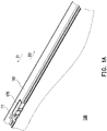
- FIG. 1A is a schematic partially enlarged view of an image capturing device in an open state according to an embodiment of the disclosure.
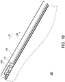
- FIG. 1B is a schematic partially enlarged view of an image capturing device in a closed state according to an embodiment of the disclosure.
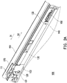
- FIG. 2A is a schematic partially omitted view of the image capturing device of FIG. 1A .
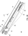
- FIG. 2B is a schematic partially omitted view of the image capturing device of FIG. 1B .
- an image capturing device 100 may be part of a portable electronic device, and the portable electronic device may be a smartphone, a tablet computer, or a notebook computer.
- the image capturing device 100 includes a casing 110, an image capturing module 120, and a shielding member 130.
- the image capturing module 120 and the shielding member 130 are both disposed in the casing 110, and the shielding member 130 is slidable with respect to the casing 110 and the image capturing module 120.
- the shielding member 130 is disposed corresponding to the image capturing module 120, and the image capturing module 120 is located at one side (e.g., the rear side) of the sliding path of the shielding member 130.
- the shielding member 130 unblocks the light path of the image capturing module 120. In other words, the light path of the image capturing module 120 is not blocked by the shielding member 130, so the image capturing module 120 may receive the external light.
- the shielding member 130 slides in a first direction D1 with respect to the casing 110 and the image capturing module 120 and blocks the light path of the image capturing module 120, so that the image capturing module 120 cannot receive the external light.
- FIG. 2B when the light path of the image capturing module 120 is blocked by the shielding member 130, even if someone (e.g., a cyber hacker) breaches the image capturing device 100 through the Internet and controls the image capturing module 120, they cannot remotely obtain the user's private image, so it is possible to prevent privacy leak.
- FIG. 3A is a schematic front view of the internal structure of the image capturing device of FIG. 2A .
- FIG. 3B is a schematic front view of the internal structure of the image capturing device of FIG. 2B .
- the shielding member 130 is rendered in broken lines in FIG. 3A and FIG. 3B .
- the image capturing device 100 further includes a positioning member 140, a memory alloy spring 150, a restoring spring 160, and a switch 170.
- the positioning member 140, the memory alloy spring 150, and the restoring spring 160 are all disposed in the casing 110, and the positioning member 140 is slidable with respect to the casing 110.
- the switch 170 is slidably disposed on the casing 110.
- a sidewall of the casing 110 is provided with a sliding groove 111 penetrating through the sidewall, and the switch 170 is slidably disposed in the sliding groove 111 for operation by the user.
- the positioning member 140 and the switch 170 are respectively connected to two end portions of the shielding member 130, and the shielding member 130, the positioning member 140, and the switch 170 may slide synchronously with respect to the casing 110.
- the memory alloy spring 150 and the restoring spring 160 are respectively located at two opposite sides of the positioning member 140. Two ends of the memory alloy spring 150 are respectively connected to the positioning member 140 and the casing 110, and two ends of the restoring spring 160 are respectively connected to the positioning member 140 and the casing 110.
- the memory alloy spring 150 may be powered to extend.
- the memory alloy spring 150 pushes the positioning member 140 to slide in the first direction D1.
- the positioning member 140 drives the shielding member 130 to slide in the first direction D1
- the shielding member 130 drives the switch 170 to slide in the first direction D1.
- the shielding member 130 blocks the light path of the image capturing module 120, as shown in FIG. 2B and FIG. 3B .
- the positioning member 140 is locked and is temporarily unable to slide with respect to the casing 110; similarly, the shielding member 130 is also temporarily unable to slide with respect to the casing 110.
- the restoring spring 160 may be a compression spring.
- the restoring spring 160 In the sliding process of the positioning member 140 in the first direction D1, the restoring spring 160 is compressed by the positioning member 140 and is elastically deformed, as shown in FIG. 3A and FIG. 3B .
- the powered and extended memory alloy spring 150 may apply an elastic force to the positioning member 140 in the first direction D1 to synchronously drive the positioning member 140, the shielding member 130, and the switch 170 to slide.
- the compressed and deformed restoring spring 160 may apply an elastic force to the positioning member 140 in a second direction D2, and the second direction D2 is opposite to the first direction D1.
- the positioning member 140 In the open state shown in FIG. 3A , the positioning member 140 is locked and is temporarily unable to slide with respect to the casing 110; similarly, the shielding member 130 is also temporarily unable to slide with respect to the casing 110.
- the memory alloy spring 150 is not powered, and the elastic force of the restoring spring 160 acting on the positioning member 140 is greater than the elastic force of the memory alloy spring 150 acting on the positioning member 140, so the memory alloy spring 150 cannot push the positioning member 140 to slide in the first direction D1.
- the elastic force of the memory alloy spring 150 acting on the positioning member 140 is greater than the elastic force of the restoring spring 160 acting on the positioning member 140 to thus unlock the positioning member 140 and drive the positioning member 140, the shielding member 130, and the switch 170 to slide in the first direction D1, so that the shielding member 130 blocks the light path of the image capturing module 120, as shown in FIG. 3B .
- the memory alloy spring 150 is powered to extend to unlock the positioning member 140.
- the extended memory alloy spring 150 may overcome the elastic force of the restoring spring 160 acting on the positioning member 140 to drive the positioning member 140 to slide in the first direction D1.
- the positioning member 140 drives the shielding member 130 to slide in the first direction D1 to block the light path of the image capturing module 120.
- the positioning member 140 In the closed state shown in FIG. 3B , the positioning member 140 is locked and is temporarily unable to slide with respect to the casing 110; similarly, the shielding member 130 is also temporarily unable to slide with respect to the casing 110.
- the memory alloy spring 150 In the switching process from the closed state shown in FIG. 3B to the open state shown in FIG. 3A , the memory alloy spring 150 is momentarily powered to unlock the positioning member 140, so that the positioning member 140 can slide with respect to the casing 110.
- the positioning member 140 After the positioning member 140 is unlocked, powering of the memory alloy spring 150 is stopped, and since the elastic force of the restoring spring 160 acting on the positioning member 140 is greater than the elastic force of the memory alloy spring 150 acting on the positioning member 140, the restoring spring 160 pushes the positioning member 140 to slide in the second direction D2, and the positioning member 140 drives the shielding member 130 to slide in the second direction D2 to unblock the light path of the image capturing module 120. At the same time, the memory alloy spring 150 is reduced from the second length L2 to the first length L1.
- the shielding member 130 includes a light transmitting part 131, a light shielding part 132 adjacent to the light transmitting part 131, and a positioning part 133 opposite to the light shielding part 132.
- the switch 170 is connected to the light shielding part 132
- the positioning member 140 is connected to the positioning part 133.
- the light transmitting part 131 may be a hole or a structure that allows light to pass through.
- the open state the light transmitting part 131 is aligned with the image capturing module 120, so that the external light may pass through the light transmitting part 131 to be received by the image capturing module 120.
- the light shielding part 132 shields the image capturing module 120. In other words, the path of the external light entering the image capturing module 120 is blocked by the light shielding part 132.
- the image capturing device 100 may be switched between the open state and the closed state and thereby exhibit excellent operating convenience.
- the positioning member 140, the shielding member 130, and the switch 170 may slide synchronously.
- the switch 170 drives the positioning member 140 to slide, and the positioning member 140 drives the shielding member 130 to slide, so that the shielding member 130 blocks or unblocks the light path of the image capturing module 120.
- the positioning member 140 In the open state shown in FIG. 3A , the positioning member 140 is locked and is temporarily unable to slide with respect to the casing 110; similarly, the shielding member 130 is also temporarily unable to slide with respect to the casing 110.
- the user may flip the switch 170 to slide in the first direction D1 to unlock the positioning member 140.
- the switch 170 also drives the positioning member 140 and the shielding member 130 to slide in the first direction D1, so that the shielding member 130 blocks the light path of the image capturing module 120, as shown in FIG. 2B and FIG. 3B .
- the restoring spring 160 In the switching process from the open state shown in FIG. 3A to the closed state shown in FIG. 3B , the restoring spring 160 is compressed by the positioning member 140 and is elastically deformed.
- the positioning member 140 In the closed state shown in FIG. 3B , the positioning member 140 is locked and is temporarily unable to slide with respect to the casing 110, so the restoring spring 160 cannot push the positioning member 140 to slide in the second direction D2.
- the shielding member 130 is also temporarily unable to slide with respect to the casing 110.
- the user may flip the switch 170 to slide in the first direction D1 to unlock the positioning member 140.
- the switch 170 is released.
- the restoring spring 160 pushes the positioning member 140 to slide in the second direction D2
- the positioning member 140 drives the shielding member 130 to slide in the second direction D2 to unblock the light path of the image capturing module 120, as shown in FIG. 2A and FIG. 3A .
- the image capturing device 100 may be switched between the open state and the closed state and thereby exhibit excellent operating convenience.
- a first operation mode is an automatic switch mode in which the image capturing device 100 is opened and closed by controlling the power-on and power-off of the memory alloy spring 150 along with the assistance of the restoring spring 160.
- a second operation mode is a manual switch mode in which the image capturing device 100 is opened and closed by flipping the switch 170 or flipping and then releasing the switch 170 along with the assistance of the restoring spring 160.
- a third operation mode is a manual-closing and automatic-opening mode in which the image capturing device 100 is closed by flipping the switch 170, and the image capturing device 100 is opened by controlling the power-on and power-off of the memory alloy spring 150 along with the assistance of the restoring spring 160.
- a fourth operation mode is an automatic-closing and manual-opening mode in which the image capturing device 100 is closed by controlling the power-on and power-off of the memory alloy spring 150, and the image capturing device 100 is opened by flipping and then releasing the switch 170 along with the assistance of the restoring spring 160.
- FIG. 4A is a schematic partially enlarged view of the positioning member and a positioning rod of FIG. 3A viewed from another viewing angle.
- FIG. 4B is a schematic partially enlarged view of the positioning member and the positioning rod of FIG. 3B viewed from another viewing angle.
- the image capturing device 100 further includes a positioning rod 180.
- the positioning rod 180 is disposed in the casing 110 and has a first end 181 and a second end 182 opposite to each other. Specifically, the first end 181 of the positioning rod 180 is pivotally connected to the casing 110, and the second end 182 is slidably connected to the positioning member 140. The second end 182 of the positioning rod 180 slides on the positioning member 140 along a predetermined annular track to limit the positioning member 140 to slide reciprocatingly within a predetermined stroke.
- the positioning member 140 has an annular positioning track 141, and the second end 182 of the positioning rod 180 is slidably connected in the positioning track 141.
- the positioning track 141 includes a first track 142, a second track 143 connected to the first track 142, a third track 144 connected to the first track 142 and the second track 143.
- the first track 142 has a first positioning point 142a
- the second track 143 has a second positioning point 143a.
- the first positioning point 142a and the second positioning point 143a are respectively located at two opposite sides of the third track 144.
- the first positioning point 142a is adjacent to the junction between the first track 142 and the third track 144
- the second positioning point 143a is adjacent to the junction between the second track 143 and the third track 144.
- the sliding path of the second end 182 of the positioning rod 180 in the positioning track 141 includes the following.
- the second end 182 of the positioning rod 180 slides from the first positioning point 142a along the first track 142 toward the second track 143, and then slides into the second track 143 and is locked at the second positioning point 143a.
- the second end 182 of the positioning rod 180 slides into the third track 144 from the second positioning point 143a, and then slides along the third track 144 toward the first track 142.
- the second end 182 of the positioning rod 180 slides into the first track 142 and is locked at the first positioning point 142a.
- FIG. 4A there is a height difference at the junction between the first track 142 and the third track 144, and the third track 144 is higher than the first track 142. Therefore, the second end 182 of the positioning rod 180 located in the first track 142 cannot slide from the first track 142 into the third track 144.
- FIG. 4B there is a height difference at the junction between the first track 142 and the second track 143, and the first track 142 is higher than the second track 143. Therefore, the second end 182 of the positioning rod 180 located in the second track 143 cannot slide from the second track 143 into the first track 142.
- the memory alloy spring 150 is not powered, the elastic force of the memory alloy spring 150 acting on the positioning member 140 is opposite to the elastic force of the restoring spring 160 acting on the positioning member 140, and the elastic force of the restoring spring 160 acting on the positioning member 140 is greater than the elastic force of the memory alloy spring 150 acting on the positioning member 140.
- the positioning member 140 is biased to slide in the second direction D2, but since the second end 182 of the positioning rod 180 structurally interferes with the positioning member 140, the second end 182 of the positioning rod 180 is locked at the first positioning point 142a of the first track 142 to prevent the positioning member 140 from sliding and ensure that the light path of the image capturing module 120 is not blocked by the shielding member 130, as shown in FIG. 2A , FIG. 3A , and FIG. 4A .
- the memory alloy spring 150 is not powered, the elastic force of the memory alloy spring 150 acting on the positioning member 140 is opposite to the elastic force of the restoring spring 160 acting on the positioning member 140, and the elastic force of the restoring spring 160 acting on the positioning member 140 is greater than the elastic force of the memory alloy spring 150 acting on the positioning member 140.
- the positioning member 140 is biased to slide in the second direction D2, but since the second end 182 of the positioning rod 180 structurally interferes with the positioning member 140, the second end 182 of the positioning rod 180 is locked at the second positioning point 143a of the second track 143 to prevent the positioning member 140 from sliding and ensure that the shielding member 130 blocks the light path of the image capturing module 120, as shown in FIG. 2B , FIG. 3B , and FIG. 4B .
- the shielding member may block the light path of the image capturing module, so that the image capturing module cannot receive the external light.
- the shielding member may block the light path of the image capturing module, so that the image capturing module cannot receive the external light.
- the shielding member even if someone (e.g., a cyber hacker) breaches the image capturing device through the Internet and controls the image capturing module, they cannot remotely obtain the user's private image, so it is possible to prevent privacy leak.
- blocking or unblocking the light path of the image capturing module may be done through the automatic switch mode, the manual switch mode, the manual-closing and automatic-opening mode, or the automatic-closing and manual-opening mode, so the image capturing device exhibits excellent operating convenience and flexibility.
Landscapes
- Engineering & Computer Science (AREA)
- Multimedia (AREA)
- Signal Processing (AREA)
- Physics & Mathematics (AREA)
- General Physics & Mathematics (AREA)
- Studio Devices (AREA)
- Separation By Low-Temperature Treatments (AREA)
- Apparatus For Radiation Diagnosis (AREA)
- Ultra Sonic Daignosis Equipment (AREA)
- Facsimile Scanning Arrangements (AREA)
- Closing And Opening Devices For Wings, And Checks For Wings (AREA)
Abstract
Description
- The disclosure relates to an image capturing device, and more particularly relates to an image capturing device with a privacy protection design.
- Common portable electronic devices (e.g., smartphones, tablet computers, or notebook computers) mostly have image capturing functions. Normally, the image capturing module is in an off-state, but an ill-intentioned person (e.g., a cyber hacker) can still breach the portable electronic device through the Internet and control the image capturing module to remotely obtain the user's private image, which thus causes privacy leak.
- The disclosure provides an image capturing device capable of preventing privacy leak.
- The disclosure provides an image capturing device including a casing, an image capturing module disposed in the casing, a positioning member slidably disposed in the casing, a memory alloy spring disposed in the casing, a restoring spring disposed in the casing, a shielding member corresponding to the image capturing module and slidably disposed in the casing, and a switch slidably disposed on the casing and connected to the shielding member. Two ends of the memory alloy spring are respectively connected to the positioning member and the casing. Two ends of the restoring spring are respectively connected to the positioning member and the casing, and the memory alloy spring and the restoring spring are respectively located at two opposite sides of the positioning member. The shielding member is connected to the positioning member. In an open state, the shielding member unblocks a light path of the image capturing module, and the memory alloy spring has a first length. In a closed state, the shielding member blocks the light path of the image capturing module, and the memory alloy spring has a second length greater than the first length.
- Based on the above, in the image capturing device of the disclosure, the shielding member may block the light path of the image capturing module, so that the image capturing module cannot receive the external light. When the light path of the image capturing module is blocked by the shielding member, even if someone (e.g., a cyber hacker) breaches the image capturing device through the Internet and controls the image capturing module, they cannot remotely obtain the user's private image, so it is possible to prevent privacy leak.
- To make the aforementioned more comprehensible, several embodiments accompanied with drawings are described in detail as follows.
-
-
FIG. 1A is a schematic partially enlarged view of an image capturing device in an open state according to an embodiment of the disclosure. -
FIG. 1B is a schematic partially enlarged view of an image capturing device in a closed state according to an embodiment of the disclosure. -
FIG. 2A is a schematic partially omitted view of the image capturing device ofFIG. 1A . -
FIG. 2B is a schematic partially omitted view of the image capturing device ofFIG. 1B . -
FIG. 3A is a schematic front view of the internal structure of the image capturing device ofFIG. 2A . -
FIG. 3B is a schematic front view of the internal structure of the image capturing device ofFIG. 2B . -
FIG. 4A is a schematic partially enlarged view of a positioning member and a positioning rod ofFIG. 3A viewed from another viewing angle. -
FIG. 4B is a schematic partially enlarged view of a positioning member and a positioning rod ofFIG. 3B viewed from another viewing angle. -
FIG. 1A is a schematic partially enlarged view of an image capturing device in an open state according to an embodiment of the disclosure.FIG. 1B is a schematic partially enlarged view of an image capturing device in a closed state according to an embodiment of the disclosure.FIG. 2A is a schematic partially omitted view of the image capturing device ofFIG. 1A .FIG. 2B is a schematic partially omitted view of the image capturing device ofFIG. 1B . Referring toFIG. 1A andFIG. 1B , in this embodiment, an image capturingdevice 100 may be part of a portable electronic device, and the portable electronic device may be a smartphone, a tablet computer, or a notebook computer. - Referring to
FIG. 1A andFIG. 2A , the image capturingdevice 100 includes acasing 110, an image capturingmodule 120, and ashielding member 130. The image capturingmodule 120 and theshielding member 130 are both disposed in thecasing 110, and theshielding member 130 is slidable with respect to thecasing 110 and theimage capturing module 120. Theshielding member 130 is disposed corresponding to the image capturingmodule 120, and theimage capturing module 120 is located at one side (e.g., the rear side) of the sliding path of theshielding member 130. In the open state shown inFIG. 2A , theshielding member 130 unblocks the light path of the image capturingmodule 120. In other words, the light path of the image capturingmodule 120 is not blocked by theshielding member 130, so the image capturingmodule 120 may receive the external light. - In the switching process from the open state shown in
FIG. 2A to the closed state shown inFIG. 2B , theshielding member 130 slides in a first direction D1 with respect to thecasing 110 and the image capturingmodule 120 and blocks the light path of theimage capturing module 120, so that the image capturingmodule 120 cannot receive the external light. As shown inFIG. 2B , when the light path of theimage capturing module 120 is blocked by the shieldingmember 130, even if someone (e.g., a cyber hacker) breaches theimage capturing device 100 through the Internet and controls theimage capturing module 120, they cannot remotely obtain the user's private image, so it is possible to prevent privacy leak. -
FIG. 3A is a schematic front view of the internal structure of the image capturing device ofFIG. 2A .FIG. 3B is a schematic front view of the internal structure of the image capturing device ofFIG. 2B . To clearly show the configuration of the internal structure, the shieldingmember 130 is rendered in broken lines inFIG. 3A andFIG. 3B . Referring toFIG. 2A andFIG. 3A , in this embodiment, theimage capturing device 100 further includes apositioning member 140, amemory alloy spring 150, a restoringspring 160, and aswitch 170. The positioningmember 140, thememory alloy spring 150, and the restoringspring 160 are all disposed in thecasing 110, and thepositioning member 140 is slidable with respect to thecasing 110. In addition, theswitch 170 is slidably disposed on thecasing 110. A sidewall of thecasing 110 is provided with a slidinggroove 111 penetrating through the sidewall, and theswitch 170 is slidably disposed in the slidinggroove 111 for operation by the user. - Referring to
FIG. 3A andFIG. 3B , the positioningmember 140 and theswitch 170 are respectively connected to two end portions of the shieldingmember 130, and the shieldingmember 130, the positioningmember 140, and theswitch 170 may slide synchronously with respect to thecasing 110. On the other hand, thememory alloy spring 150 and the restoringspring 160 are respectively located at two opposite sides of thepositioning member 140. Two ends of thememory alloy spring 150 are respectively connected to thepositioning member 140 and thecasing 110, and two ends of the restoringspring 160 are respectively connected to thepositioning member 140 and thecasing 110. - In this embodiment, the
memory alloy spring 150 may be powered to extend. When thememory alloy spring 150 extends from a first length L1 to a second length L2, thememory alloy spring 150 pushes thepositioning member 140 to slide in the first direction D1. At the same time, the positioningmember 140 drives the shieldingmember 130 to slide in the first direction D1, and the shieldingmember 130 drives theswitch 170 to slide in the first direction D1. Finally, the shieldingmember 130 blocks the light path of theimage capturing module 120, as shown inFIG. 2B andFIG. 3B . In the closed state shown inFIG. 3B , the positioningmember 140 is locked and is temporarily unable to slide with respect to thecasing 110; similarly, the shieldingmember 130 is also temporarily unable to slide with respect to thecasing 110. - On the other hand, the restoring
spring 160 may be a compression spring. In the sliding process of thepositioning member 140 in the first direction D1, the restoringspring 160 is compressed by the positioningmember 140 and is elastically deformed, as shown inFIG. 3A andFIG. 3B . Further, the powered and extendedmemory alloy spring 150 may apply an elastic force to thepositioning member 140 in the first direction D1 to synchronously drive the positioningmember 140, the shieldingmember 130, and theswitch 170 to slide. At the same time, the compressed and deformed restoringspring 160 may apply an elastic force to thepositioning member 140 in a second direction D2, and the second direction D2 is opposite to the first direction D1. - In the open state shown in
FIG. 3A , the positioningmember 140 is locked and is temporarily unable to slide with respect to thecasing 110; similarly, the shieldingmember 130 is also temporarily unable to slide with respect to thecasing 110. Specifically, thememory alloy spring 150 is not powered, and the elastic force of the restoringspring 160 acting on thepositioning member 140 is greater than the elastic force of thememory alloy spring 150 acting on thepositioning member 140, so thememory alloy spring 150 cannot push thepositioning member 140 to slide in the first direction D1. - When the
memory alloy spring 150 is powered, the elastic force of thememory alloy spring 150 acting on thepositioning member 140 is greater than the elastic force of the restoringspring 160 acting on thepositioning member 140 to thus unlock thepositioning member 140 and drive the positioningmember 140, the shieldingmember 130, and theswitch 170 to slide in the first direction D1, so that the shieldingmember 130 blocks the light path of theimage capturing module 120, as shown inFIG. 3B . From another perspective, thememory alloy spring 150 is powered to extend to unlock thepositioning member 140. In other words, the extendedmemory alloy spring 150 may overcome the elastic force of the restoringspring 160 acting on thepositioning member 140 to drive the positioningmember 140 to slide in the first direction D1. At the same time, the positioningmember 140 drives the shieldingmember 130 to slide in the first direction D1 to block the light path of theimage capturing module 120. - In the closed state shown in
FIG. 3B , the positioningmember 140 is locked and is temporarily unable to slide with respect to thecasing 110; similarly, the shieldingmember 130 is also temporarily unable to slide with respect to thecasing 110. In the switching process from the closed state shown inFIG. 3B to the open state shown inFIG. 3A , thememory alloy spring 150 is momentarily powered to unlock thepositioning member 140, so that thepositioning member 140 can slide with respect to thecasing 110. After thepositioning member 140 is unlocked, powering of thememory alloy spring 150 is stopped, and since the elastic force of the restoringspring 160 acting on thepositioning member 140 is greater than the elastic force of thememory alloy spring 150 acting on thepositioning member 140, the restoringspring 160 pushes thepositioning member 140 to slide in the second direction D2, and thepositioning member 140 drives the shieldingmember 130 to slide in the second direction D2 to unblock the light path of theimage capturing module 120. At the same time, thememory alloy spring 150 is reduced from the second length L2 to the first length L1. - Referring to
FIG. 2A andFIG. 3A , in this embodiment, the shieldingmember 130 includes alight transmitting part 131, alight shielding part 132 adjacent to thelight transmitting part 131, and apositioning part 133 opposite to thelight shielding part 132. Theswitch 170 is connected to thelight shielding part 132, and thepositioning member 140 is connected to thepositioning part 133. For example, thelight transmitting part 131 may be a hole or a structure that allows light to pass through. In the open state, thelight transmitting part 131 is aligned with theimage capturing module 120, so that the external light may pass through thelight transmitting part 131 to be received by theimage capturing module 120. As shown inFIG. 2B andFIG. 3B , in the closed state, thelight shielding part 132 shields theimage capturing module 120. In other words, the path of the external light entering theimage capturing module 120 is blocked by thelight shielding part 132. - Referring to
FIG. 2A to FIG. 3B , by controlling the power-on and power-off of thememory alloy spring 150, theimage capturing device 100 may be switched between the open state and the closed state and thereby exhibit excellent operating convenience. - Referring to
FIG. 2A to FIG. 3B , in this embodiment, the positioningmember 140, the shieldingmember 130, and theswitch 170 may slide synchronously. When the user flips theswitch 170, theswitch 170 drives thepositioning member 140 to slide, and thepositioning member 140 drives the shieldingmember 130 to slide, so that the shieldingmember 130 blocks or unblocks the light path of theimage capturing module 120. - In the open state shown in
FIG. 3A , the positioningmember 140 is locked and is temporarily unable to slide with respect to thecasing 110; similarly, the shieldingmember 130 is also temporarily unable to slide with respect to thecasing 110. The user may flip theswitch 170 to slide in the first direction D1 to unlock thepositioning member 140. At the same time, theswitch 170 also drives thepositioning member 140 and the shieldingmember 130 to slide in the first direction D1, so that the shieldingmember 130 blocks the light path of theimage capturing module 120, as shown inFIG. 2B andFIG. 3B . In the switching process from the open state shown inFIG. 3A to the closed state shown inFIG. 3B , the restoringspring 160 is compressed by the positioningmember 140 and is elastically deformed. - In the closed state shown in
FIG. 3B , the positioningmember 140 is locked and is temporarily unable to slide with respect to thecasing 110, so the restoringspring 160 cannot push thepositioning member 140 to slide in the second direction D2. Similarly, the shieldingmember 130 is also temporarily unable to slide with respect to thecasing 110. The user may flip theswitch 170 to slide in the first direction D1 to unlock thepositioning member 140. Next, theswitch 170 is released. Then, the restoringspring 160 pushes thepositioning member 140 to slide in the second direction D2, and thepositioning member 140 drives the shieldingmember 130 to slide in the second direction D2 to unblock the light path of theimage capturing module 120, as shown inFIG. 2A andFIG. 3A . - Referring to
FIG. 2A to FIG. 3B , by flipping theswitch 170 or flipping and then releasing theswitch 170, theimage capturing device 100 may be switched between the open state and the closed state and thereby exhibit excellent operating convenience. - Further, the opening (i.e., unblocking the light path of the
image capturing module 120 by the shielding member 130) and the closing (i.e., blocking the light path of theimage capturing module 120 by the shielding member 130) of theimage capturing device 100 may be done through multiple operation modes, so theimage capturing device 100 exhibits excellent operating convenience and flexibility. Specifically, a first operation mode is an automatic switch mode in which theimage capturing device 100 is opened and closed by controlling the power-on and power-off of thememory alloy spring 150 along with the assistance of the restoringspring 160. A second operation mode is a manual switch mode in which theimage capturing device 100 is opened and closed by flipping theswitch 170 or flipping and then releasing theswitch 170 along with the assistance of the restoringspring 160. A third operation mode is a manual-closing and automatic-opening mode in which theimage capturing device 100 is closed by flipping theswitch 170, and theimage capturing device 100 is opened by controlling the power-on and power-off of thememory alloy spring 150 along with the assistance of the restoringspring 160. A fourth operation mode is an automatic-closing and manual-opening mode in which theimage capturing device 100 is closed by controlling the power-on and power-off of thememory alloy spring 150, and theimage capturing device 100 is opened by flipping and then releasing theswitch 170 along with the assistance of the restoringspring 160. -
FIG. 4A is a schematic partially enlarged view of the positioning member and a positioning rod ofFIG. 3A viewed from another viewing angle.FIG. 4B is a schematic partially enlarged view of the positioning member and the positioning rod ofFIG. 3B viewed from another viewing angle. Referring toFIG. 3A andFIG. 4A , in this embodiment, theimage capturing device 100 further includes apositioning rod 180. Thepositioning rod 180 is disposed in thecasing 110 and has afirst end 181 and asecond end 182 opposite to each other. Specifically, thefirst end 181 of thepositioning rod 180 is pivotally connected to thecasing 110, and thesecond end 182 is slidably connected to thepositioning member 140. Thesecond end 182 of thepositioning rod 180 slides on thepositioning member 140 along a predetermined annular track to limit thepositioning member 140 to slide reciprocatingly within a predetermined stroke. - The positioning
member 140 has anannular positioning track 141, and thesecond end 182 of thepositioning rod 180 is slidably connected in thepositioning track 141. In this embodiment, thepositioning track 141 includes afirst track 142, asecond track 143 connected to thefirst track 142, athird track 144 connected to thefirst track 142 and thesecond track 143. Thefirst track 142 has afirst positioning point 142a, and thesecond track 143 has asecond positioning point 143a. On the other hand, thefirst positioning point 142a and thesecond positioning point 143a are respectively located at two opposite sides of thethird track 144. Thefirst positioning point 142a is adjacent to the junction between thefirst track 142 and thethird track 144, and thesecond positioning point 143a is adjacent to the junction between thesecond track 143 and thethird track 144. - Referring to
FIG. 3A to FIG. 4B , in the sliding process of thepositioning member 140 first in the first direction D1 and then in the second direction D2, the sliding path of thesecond end 182 of thepositioning rod 180 in thepositioning track 141 includes the following. Thesecond end 182 of thepositioning rod 180 slides from thefirst positioning point 142a along thefirst track 142 toward thesecond track 143, and then slides into thesecond track 143 and is locked at thesecond positioning point 143a. Next, thesecond end 182 of thepositioning rod 180 slides into thethird track 144 from thesecond positioning point 143a, and then slides along thethird track 144 toward thefirst track 142. Finally, thesecond end 182 of thepositioning rod 180 slides into thefirst track 142 and is locked at thefirst positioning point 142a. - Referring to
FIG. 4A , there is a height difference at the junction between thefirst track 142 and thethird track 144, and thethird track 144 is higher than thefirst track 142. Therefore, thesecond end 182 of thepositioning rod 180 located in thefirst track 142 cannot slide from thefirst track 142 into thethird track 144. Referring toFIG. 4B , there is a height difference at the junction between thefirst track 142 and thesecond track 143, and thefirst track 142 is higher than thesecond track 143. Therefore, thesecond end 182 of thepositioning rod 180 located in thesecond track 143 cannot slide from thesecond track 143 into thefirst track 142. Referring toFIG. 4B again, there is a height difference at the junction between thesecond track 143 and thethird track 144, and thesecond track 143 is higher than thethird track 144. Therefore, once thesecond end 182 of thepositioning rod 180 slides into thethird track 144, thesecond end 182 of thepositioning rod 180 cannot slide from thethird track 144 into thesecond track 143. - In the open state shown in
FIG. 3A , thememory alloy spring 150 is not powered, the elastic force of thememory alloy spring 150 acting on thepositioning member 140 is opposite to the elastic force of the restoringspring 160 acting on thepositioning member 140, and the elastic force of the restoringspring 160 acting on thepositioning member 140 is greater than the elastic force of thememory alloy spring 150 acting on thepositioning member 140. In other words, the positioningmember 140 is biased to slide in the second direction D2, but since thesecond end 182 of thepositioning rod 180 structurally interferes with the positioningmember 140, thesecond end 182 of thepositioning rod 180 is locked at thefirst positioning point 142a of thefirst track 142 to prevent thepositioning member 140 from sliding and ensure that the light path of theimage capturing module 120 is not blocked by the shieldingmember 130, as shown inFIG. 2A ,FIG. 3A , andFIG. 4A . - In the closed state shown in
FIG. 3B , thememory alloy spring 150 is not powered, the elastic force of thememory alloy spring 150 acting on thepositioning member 140 is opposite to the elastic force of the restoringspring 160 acting on thepositioning member 140, and the elastic force of the restoringspring 160 acting on thepositioning member 140 is greater than the elastic force of thememory alloy spring 150 acting on thepositioning member 140. In other words, the positioningmember 140 is biased to slide in the second direction D2, but since thesecond end 182 of thepositioning rod 180 structurally interferes with the positioningmember 140, thesecond end 182 of thepositioning rod 180 is locked at thesecond positioning point 143a of thesecond track 143 to prevent thepositioning member 140 from sliding and ensure that the shieldingmember 130 blocks the light path of theimage capturing module 120, as shown inFIG. 2B ,FIG. 3B , andFIG. 4B . - In summary of the above, in the image capturing device of the disclosure, the shielding member may block the light path of the image capturing module, so that the image capturing module cannot receive the external light. When the light path of the image capturing module is blocked by the shielding member, even if someone (e.g., a cyber hacker) breaches the image capturing device through the Internet and controls the image capturing module, they cannot remotely obtain the user's private image, so it is possible to prevent privacy leak. Furthermore, blocking or unblocking the light path of the image capturing module may be done through the automatic switch mode, the manual switch mode, the manual-closing and automatic-opening mode, or the automatic-closing and manual-opening mode, so the image capturing device exhibits excellent operating convenience and flexibility.
Claims (13)
- An image capturing device (100) comprising:a casing (110);an image capturing module (120) disposed in the casing (110);a positioning member (140) slidably disposed in the casing (110);a memory alloy spring (150) disposed in the casing (110), wherein two ends of the memory alloy spring (150) are respectively connected to the positioning member (140) and the casing (110);a restoring spring (160) disposed in the casing (110), wherein two ends of the restoring spring (160) are respectively connected to the positioning member (140) and the casing (110), and the memory alloy spring (150) and the restoring spring (160) are respectively located at two opposite sides of the positioning member (140);a shielding member (130) corresponding to the image capturing module (120) and slidably disposed in the casing (110), wherein the shielding member (130) is connected to the positioning member (140), and in an open state, the shielding member (130) unblocks a light path of the image capturing module (120), and the memory alloy spring (150) has a first length, and in a closed state, the shielding member (130) blocks the light path of the image capturing module (120), and the memory alloy spring (150) has a second length greater than the first length; anda switch (170) slidably disposed on the casing (110) and connected to the shielding member (130).
- The image capturing device (100) according to claim 1, further comprising:
a positioning rod (180) disposed in the casing (110) and having a first end and a second end opposite to each other, wherein the first end is pivotally connected to the casing (110), and the second end is slidably connected to the positioning member (140). - The image capturing device (100) according to claim 2, wherein the positioning member (140) has a positioning track, the second end is slidably connected in the positioning track, and the positioning track comprises a first track, a second track connected to the first track, and a third track connected to the first track and the second track, wherein the first track has a first positioning point, the second track has a second positioning point, and the first positioning point and the second positioning point are respectively located at two opposite sides of the third track.
- The image capturing device (100) according to claim 3, wherein a sliding path of the second end of the positioning rod (180) in the positioning track comprises sliding from the first positioning point along the first track toward the second track, then sliding into the second track and being lock at the second positioning point, then sliding from the second positioning point into the third track, then sliding along the third track toward the first track, and finally sliding into the first track and being locked at the first positioning point.
- The image capturing device (100) according to claim 3, wherein an elastic force of the memory alloy spring (150) acting on the positioning member (140) is opposite to an elastic force of the restoring spring (160) acting on the positioning member (140), and the elastic force of the restoring spring (160) acting on the positioning member (140) is greater than the elastic force of the memory alloy spring (150) acting on the positioning member (140), so that the second end of the positioning rod (180) is locked at the first positioning point, and the shielding member (130) unblocks the light path of the image capturing module (120).
- The image capturing device (100) according to claim 3, wherein an elastic force of the memory alloy spring (150) acting on the positioning member (140) is opposite to an elastic force of the restoring spring (160) acting on the positioning member (140), and the elastic force of the restoring spring (160) acting on the positioning member (140) is greater than the elastic force of the memory alloy spring (150) acting on the positioning member (140), so that the second end of the positioning rod (180) is locked at the second positioning point, and the shielding member (130) blocks the light path of the image capturing module (120).
- The image capturing device (100) according to claim 1, wherein the memory alloy spring (150) extends from the first length to the second length to push the positioning member (140), and the positioning member (140) drives the shielding member (130) and compresses the restoring spring (160), so that the shielding member (130) blocks the light path of the image capturing module (120).
- The image capturing device (100) according to claim 1, wherein the restoring spring (160) pushes the positioning member (140), and the positioning member (140) drives the shielding member (130), so that the shielding member (130) unblocks the light path of the image capturing module (120), and the memory alloy spring (150) is reduced from the second length to the first length.
- The image capturing device (100) according to claim 1, wherein an elastic force of the memory alloy spring (150) acting on the positioning member (140) is opposite to an elastic force of the restoring spring (160) acting on the positioning member (140), the elastic force of the memory alloy spring (150), when powered, acting on the positioning member (140) is greater than the elastic force of the restoring spring (160) acting on the positioning member (140), and the elastic force of the memory alloy spring (150), when unpowered, acting on the positioning member (140) is less than the elastic force of the restoring spring (160) acting on the positioning member (140).
- The image capturing device (100) according to claim 1, wherein the restoring spring (160) comprises a compression spring.
- The image capturing device (100) according to claim 1, wherein the shielding member (130) unblocks the light path of the image capturing module (120), and the positioning member (140) is locked, wherein in an operation mode, a force is applied to push the switch (170) to slide in a first direction to unlock the positioning member (140) and drive the shielding member (130) and the positioning member (140) to slide in the first direction, so that the shielding member (130) blocks the light path of the image capturing module (120), and in another operation mode, the memory alloy spring (150) is powered to extend to unlock the positioning member (140) and drive the positioning member (140) and the shielding member (130) to slide in the first direction, so that the shielding member (130) blocks the light path of the image capturing module (120).
- The image capturing device (100) according to claim 1, wherein the shielding member (130) blocks the light path of the image capturing module (120), the positioning member (140) is locked, and the restoring spring (160) is compressed, wherein in an operation mode, a force is applied to push the switch (170) to slide in the first direction to unlock the positioning member (140), and then the restoring spring (160) drives the positioning member (140) and the shielding member (130) to slide in a second direction opposite to the first direction, so that the shielding member (130) unblocks the light path of the image capturing module (120), and in another operation mode, the memory alloy spring (150) is powered to extend to unlock the positioning member (140), and then the restoring spring (160) drives the positioning member (140) and the shielding member (130) to slide in the second direction opposite to the first direction, so that the shielding member (130) unblocks the light path of the image capturing module (120).
- The image capturing device (100) according to claim 1, wherein the shielding member (130) comprises a light transmitting part (131), a light shielding part (132) adjacent to the light transmitting part (131), and a positioning part (133) opposite to the light shielding part (132), wherein the switch (170) is connected to the light shielding part (132), and the positioning member (140) is connected to the positioning part (133), wherein in the open state, the light transmitting part (131) is aligned with the image capturing module (120), and in the closed state, the light shielding part (132) shields the image capturing module (120).
Applications Claiming Priority (1)
| Application Number | Priority Date | Filing Date | Title |
|---|---|---|---|
| TW110118268A TWI811682B (en) | 2021-05-20 | 2021-05-20 | Image capturing device |
Publications (2)
| Publication Number | Publication Date |
|---|---|
| EP4093014A1 true EP4093014A1 (en) | 2022-11-23 |
| EP4093014B1 EP4093014B1 (en) | 2025-11-05 |
Family
ID=81346584
Family Applications (1)
| Application Number | Title | Priority Date | Filing Date |
|---|---|---|---|
| EP22165987.3A Active EP4093014B1 (en) | 2021-05-20 | 2022-03-31 | Image capturing device |
Country Status (3)
| Country | Link |
|---|---|
| US (1) | US11703742B2 (en) |
| EP (1) | EP4093014B1 (en) |
| TW (1) | TWI811682B (en) |
Cited By (1)
| Publication number | Priority date | Publication date | Assignee | Title |
|---|---|---|---|---|
| GB2625883A (en) * | 2022-11-01 | 2024-07-03 | Tymphany Hk Ltd | Shielding structure and electronic device having the same |
Citations (3)
| Publication number | Priority date | Publication date | Assignee | Title |
|---|---|---|---|---|
| KR20050006690A (en) * | 2003-07-10 | 2005-01-17 | 김영춘 | Door opening and closing device for camera lens |
| WO2020068099A1 (en) * | 2018-09-28 | 2020-04-02 | Hewlett-Packard Development Company, L.P. | Camera shutters |
| US20210081003A1 (en) * | 2019-09-13 | 2021-03-18 | Facebook Technologies, Llc | Interactive display system with multifunctional privacy switch |
Family Cites Families (7)
| Publication number | Priority date | Publication date | Assignee | Title |
|---|---|---|---|---|
| JP5277801B2 (en) * | 2008-09-04 | 2013-08-28 | カシオ計算機株式会社 | Image reproducing apparatus and program |
| US8724020B1 (en) * | 2013-12-10 | 2014-05-13 | Vysk Communications, Inc. | Microphone and camera disruption apparatus and method |
| KR102493579B1 (en) * | 2018-01-08 | 2023-01-31 | 삼성전자주식회사 | Electronic device including camera and method for controlling the electronic device |
| CN110082984B (en) * | 2018-01-25 | 2021-11-30 | 台湾东电化股份有限公司 | lens unit |
| CN111580322B (en) * | 2019-02-18 | 2025-03-28 | 新思考电机有限公司 | Aperture switching device and photographic device and electronic equipment |
| CN110244500A (en) * | 2019-05-31 | 2019-09-17 | 领先科技(东台)有限公司 | A kind of double sliding desk type camera radical occlusion devices |
| TWI710882B (en) * | 2019-12-31 | 2020-11-21 | 宏碁股份有限公司 | Portable electronic device |
-
2021
- 2021-05-20 TW TW110118268A patent/TWI811682B/en active
-
2022
- 2022-03-25 US US17/704,029 patent/US11703742B2/en active Active
- 2022-03-31 EP EP22165987.3A patent/EP4093014B1/en active Active
Patent Citations (3)
| Publication number | Priority date | Publication date | Assignee | Title |
|---|---|---|---|---|
| KR20050006690A (en) * | 2003-07-10 | 2005-01-17 | 김영춘 | Door opening and closing device for camera lens |
| WO2020068099A1 (en) * | 2018-09-28 | 2020-04-02 | Hewlett-Packard Development Company, L.P. | Camera shutters |
| US20210081003A1 (en) * | 2019-09-13 | 2021-03-18 | Facebook Technologies, Llc | Interactive display system with multifunctional privacy switch |
Cited By (2)
| Publication number | Priority date | Publication date | Assignee | Title |
|---|---|---|---|---|
| GB2625883A (en) * | 2022-11-01 | 2024-07-03 | Tymphany Hk Ltd | Shielding structure and electronic device having the same |
| GB2625883B (en) * | 2022-11-01 | 2025-02-05 | Tymphany Hk Ltd | Shielding structure and electronic device having the same |
Also Published As
| Publication number | Publication date |
|---|---|
| EP4093014B1 (en) | 2025-11-05 |
| US20220373864A1 (en) | 2022-11-24 |
| TW202246871A (en) | 2022-12-01 |
| TWI811682B (en) | 2023-08-11 |
| US11703742B2 (en) | 2023-07-18 |
Similar Documents
| Publication | Publication Date | Title |
|---|---|---|
| US9854142B2 (en) | Security door for electronic communication devices | |
| US9553408B2 (en) | USB port locking device | |
| US7991442B2 (en) | Multiple opening and closing type mobile communication terminal | |
| US9390746B2 (en) | Gate structure and electronic device using the same | |
| HUP0501059A2 (en) | Portable electronic device physical security device | |
| US20190246014A1 (en) | Shelter module | |
| EP4093014B1 (en) | Image capturing device | |
| US8274788B2 (en) | Locking mechanism and portable computer utilizing the same | |
| US10884459B1 (en) | Electronic device and moving module thereof | |
| KR102120143B1 (en) | Lens module | |
| TWI639879B (en) | Security shielding device for camera lens | |
| KR20180032157A (en) | An apparatus for locking usb cable | |
| CN105988513A (en) | Camera component | |
| CN115396568B (en) | Image pickup apparatus | |
| TWM563722U (en) | Lockable flip cover structure for electronic devices | |
| TWI831149B (en) | Electronic device with rotatable display | |
| US12101539B2 (en) | Information handling system camera shutter with secondary security by power removal | |
| KR200395863Y1 (en) | Push-Push type mobile communication terminal | |
| CN212304050U (en) | Interface panel protector and multimedia platform | |
| US12284449B2 (en) | Information handling system camera shutter with audio feedback of position change | |
| US12547051B2 (en) | Camera module and electronic device | |
| KR100592655B1 (en) | Cushion device of mobile communication terminal | |
| US12212833B2 (en) | Information handling system camera shutter with external fail safe | |
| US20260057720A1 (en) | Invisible e-lock door and electronic device using same | |
| US20240231188A1 (en) | Information handling system electromechanical camera shutter with plural apertures |
Legal Events
| Date | Code | Title | Description |
|---|---|---|---|
| PUAI | Public reference made under article 153(3) epc to a published international application that has entered the european phase |
Free format text: ORIGINAL CODE: 0009012 |
|
| STAA | Information on the status of an ep patent application or granted ep patent |
Free format text: STATUS: THE APPLICATION HAS BEEN PUBLISHED |
|
| AK | Designated contracting states |
Kind code of ref document: A1 Designated state(s): AL AT BE BG CH CY CZ DE DK EE ES FI FR GB GR HR HU IE IS IT LI LT LU LV MC MK MT NL NO PL PT RO RS SE SI SK SM TR |
|
| STAA | Information on the status of an ep patent application or granted ep patent |
Free format text: STATUS: REQUEST FOR EXAMINATION WAS MADE |
|
| 17P | Request for examination filed |
Effective date: 20221128 |
|
| RBV | Designated contracting states (corrected) |
Designated state(s): AL AT BE BG CH CY CZ DE DK EE ES FI FR GB GR HR HU IE IS IT LI LT LU LV MC MK MT NL NO PL PT RO RS SE SI SK SM TR |
|
| STAA | Information on the status of an ep patent application or granted ep patent |
Free format text: STATUS: EXAMINATION IS IN PROGRESS |
|
| 17Q | First examination report despatched |
Effective date: 20240213 |
|
| REG | Reference to a national code |
Ref legal event code: R079 Ipc: H04N0023510000 Ref country code: DE Ref legal event code: R079 Ref document number: 602022024260 Country of ref document: DE Free format text: PREVIOUS MAIN CLASS: H04N0005225000 Ipc: H04N0023510000 |
|
| GRAP | Despatch of communication of intention to grant a patent |
Free format text: ORIGINAL CODE: EPIDOSNIGR1 |
|
| STAA | Information on the status of an ep patent application or granted ep patent |
Free format text: STATUS: GRANT OF PATENT IS INTENDED |
|
| RIC1 | Information provided on ipc code assigned before grant |
Ipc: G03B 11/04 20210101ALI20250522BHEP Ipc: H04N 23/57 20230101ALI20250522BHEP Ipc: H04N 23/55 20230101ALI20250522BHEP Ipc: H04N 23/51 20230101AFI20250522BHEP |
|
| INTG | Intention to grant announced |
Effective date: 20250617 |
|
| RIN1 | Information on inventor provided before grant (corrected) |
Inventor name: WEN, CHUN-HUNG Inventor name: CHEN, CHUN-HSIEN Inventor name: SUN, HUI-PING Inventor name: CHUEH, YEN-CHOU |
|
| GRAS | Grant fee paid |
Free format text: ORIGINAL CODE: EPIDOSNIGR3 |
|
| GRAA | (expected) grant |
Free format text: ORIGINAL CODE: 0009210 |
|
| STAA | Information on the status of an ep patent application or granted ep patent |
Free format text: STATUS: THE PATENT HAS BEEN GRANTED |
|
| AK | Designated contracting states |
Kind code of ref document: B1 Designated state(s): AL AT BE BG CH CY CZ DE DK EE ES FI FR GB GR HR HU IE IS IT LI LT LU LV MC MK MT NL NO PL PT RO RS SE SI SK SM TR |
|
| REG | Reference to a national code |
Ref country code: CH Ref legal event code: F10 Free format text: ST27 STATUS EVENT CODE: U-0-0-F10-F00 (AS PROVIDED BY THE NATIONAL OFFICE) Effective date: 20251105 Ref country code: GB Ref legal event code: FG4D |
|
| REG | Reference to a national code |
Ref country code: DE Ref legal event code: R096 Ref document number: 602022024260 Country of ref document: DE |
|
| REG | Reference to a national code |
Ref country code: IE Ref legal event code: FG4D |
|
| REG | Reference to a national code |
Ref country code: NL Ref legal event code: MP Effective date: 20251105 |
|
| PGFP | Annual fee paid to national office [announced via postgrant information from national office to epo] |
Ref country code: GB Payment date: 20260209 Year of fee payment: 5 |
|
| PG25 | Lapsed in a contracting state [announced via postgrant information from national office to epo] |
Ref country code: ES Free format text: LAPSE BECAUSE OF FAILURE TO SUBMIT A TRANSLATION OF THE DESCRIPTION OR TO PAY THE FEE WITHIN THE PRESCRIBED TIME-LIMIT Effective date: 20251105 |
|
| REG | Reference to a national code |
Ref country code: LT Ref legal event code: MG9D |
|
| PG25 | Lapsed in a contracting state [announced via postgrant information from national office to epo] |
Ref country code: NO Free format text: LAPSE BECAUSE OF FAILURE TO SUBMIT A TRANSLATION OF THE DESCRIPTION OR TO PAY THE FEE WITHIN THE PRESCRIBED TIME-LIMIT Effective date: 20260205 |
|
| PGFP | Annual fee paid to national office [announced via postgrant information from national office to epo] |
Ref country code: DE Payment date: 20260204 Year of fee payment: 5 |
|
| PG25 | Lapsed in a contracting state [announced via postgrant information from national office to epo] |
Ref country code: HR Free format text: LAPSE BECAUSE OF FAILURE TO SUBMIT A TRANSLATION OF THE DESCRIPTION OR TO PAY THE FEE WITHIN THE PRESCRIBED TIME-LIMIT Effective date: 20251105 Ref country code: AT Free format text: LAPSE BECAUSE OF FAILURE TO SUBMIT A TRANSLATION OF THE DESCRIPTION OR TO PAY THE FEE WITHIN THE PRESCRIBED TIME-LIMIT Effective date: 20251105 Ref country code: FI Free format text: LAPSE BECAUSE OF FAILURE TO SUBMIT A TRANSLATION OF THE DESCRIPTION OR TO PAY THE FEE WITHIN THE PRESCRIBED TIME-LIMIT Effective date: 20251105 |
|
| REG | Reference to a national code |
Ref country code: AT Ref legal event code: MK05 Ref document number: 1855713 Country of ref document: AT Kind code of ref document: T Effective date: 20251105 |
|
| PG25 | Lapsed in a contracting state [announced via postgrant information from national office to epo] |
Ref country code: NL Free format text: LAPSE BECAUSE OF FAILURE TO SUBMIT A TRANSLATION OF THE DESCRIPTION OR TO PAY THE FEE WITHIN THE PRESCRIBED TIME-LIMIT Effective date: 20251105 |
|
| PG25 | Lapsed in a contracting state [announced via postgrant information from national office to epo] |
Ref country code: RS Free format text: LAPSE BECAUSE OF FAILURE TO SUBMIT A TRANSLATION OF THE DESCRIPTION OR TO PAY THE FEE WITHIN THE PRESCRIBED TIME-LIMIT Effective date: 20260205 |
|
| PG25 | Lapsed in a contracting state [announced via postgrant information from national office to epo] |
Ref country code: IS Free format text: LAPSE BECAUSE OF FAILURE TO SUBMIT A TRANSLATION OF THE DESCRIPTION OR TO PAY THE FEE WITHIN THE PRESCRIBED TIME-LIMIT Effective date: 20260305 |
|
| PGFP | Annual fee paid to national office [announced via postgrant information from national office to epo] |
Ref country code: FR Payment date: 20260209 Year of fee payment: 5 |
|
| PG25 | Lapsed in a contracting state [announced via postgrant information from national office to epo] |
Ref country code: PT Free format text: LAPSE BECAUSE OF FAILURE TO SUBMIT A TRANSLATION OF THE DESCRIPTION OR TO PAY THE FEE WITHIN THE PRESCRIBED TIME-LIMIT Effective date: 20260305 |
|
| PG25 | Lapsed in a contracting state [announced via postgrant information from national office to epo] |
Ref country code: PL Free format text: LAPSE BECAUSE OF FAILURE TO SUBMIT A TRANSLATION OF THE DESCRIPTION OR TO PAY THE FEE WITHIN THE PRESCRIBED TIME-LIMIT Effective date: 20251105 |
|
| PG25 | Lapsed in a contracting state [announced via postgrant information from national office to epo] |
Ref country code: LV Free format text: LAPSE BECAUSE OF FAILURE TO SUBMIT A TRANSLATION OF THE DESCRIPTION OR TO PAY THE FEE WITHIN THE PRESCRIBED TIME-LIMIT Effective date: 20251105 |
|
| PG25 | Lapsed in a contracting state [announced via postgrant information from national office to epo] |
Ref country code: BG Free format text: LAPSE BECAUSE OF FAILURE TO SUBMIT A TRANSLATION OF THE DESCRIPTION OR TO PAY THE FEE WITHIN THE PRESCRIBED TIME-LIMIT Effective date: 20251105 |
|
| PG25 | Lapsed in a contracting state [announced via postgrant information from national office to epo] |
Ref country code: LT Free format text: LAPSE BECAUSE OF FAILURE TO SUBMIT A TRANSLATION OF THE DESCRIPTION OR TO PAY THE FEE WITHIN THE PRESCRIBED TIME-LIMIT Effective date: 20251105 |
|
| PG25 | Lapsed in a contracting state [announced via postgrant information from national office to epo] |
Ref country code: SM Free format text: LAPSE BECAUSE OF FAILURE TO SUBMIT A TRANSLATION OF THE DESCRIPTION OR TO PAY THE FEE WITHIN THE PRESCRIBED TIME-LIMIT Effective date: 20251105 |
|
| PG25 | Lapsed in a contracting state [announced via postgrant information from national office to epo] |
Ref country code: DK Free format text: LAPSE BECAUSE OF FAILURE TO SUBMIT A TRANSLATION OF THE DESCRIPTION OR TO PAY THE FEE WITHIN THE PRESCRIBED TIME-LIMIT Effective date: 20251105 |
|
| PG25 | Lapsed in a contracting state [announced via postgrant information from national office to epo] |
Ref country code: IT Free format text: LAPSE BECAUSE OF FAILURE TO SUBMIT A TRANSLATION OF THE DESCRIPTION OR TO PAY THE FEE WITHIN THE PRESCRIBED TIME-LIMIT Effective date: 20251105 |
|
| PG25 | Lapsed in a contracting state [announced via postgrant information from national office to epo] |
Ref country code: EE Free format text: LAPSE BECAUSE OF FAILURE TO SUBMIT A TRANSLATION OF THE DESCRIPTION OR TO PAY THE FEE WITHIN THE PRESCRIBED TIME-LIMIT Effective date: 20251105 |
|
| PG25 | Lapsed in a contracting state [announced via postgrant information from national office to epo] |
Ref country code: CZ Free format text: LAPSE BECAUSE OF FAILURE TO SUBMIT A TRANSLATION OF THE DESCRIPTION OR TO PAY THE FEE WITHIN THE PRESCRIBED TIME-LIMIT Effective date: 20251105 |
|
| PG25 | Lapsed in a contracting state [announced via postgrant information from national office to epo] |
Ref country code: SK Free format text: LAPSE BECAUSE OF FAILURE TO SUBMIT A TRANSLATION OF THE DESCRIPTION OR TO PAY THE FEE WITHIN THE PRESCRIBED TIME-LIMIT Effective date: 20251105 |
|
| PG25 | Lapsed in a contracting state [announced via postgrant information from national office to epo] |
Ref country code: SE Free format text: LAPSE BECAUSE OF FAILURE TO SUBMIT A TRANSLATION OF THE DESCRIPTION OR TO PAY THE FEE WITHIN THE PRESCRIBED TIME-LIMIT Effective date: 20251105 |