EP4093007A1 - Image forming device - Google Patents
Image forming device Download PDFInfo
- Publication number
- EP4093007A1 EP4093007A1 EP22160434.1A EP22160434A EP4093007A1 EP 4093007 A1 EP4093007 A1 EP 4093007A1 EP 22160434 A EP22160434 A EP 22160434A EP 4093007 A1 EP4093007 A1 EP 4093007A1
- Authority
- EP
- European Patent Office
- Prior art keywords
- wireless tag
- sheet
- conductor
- image forming
- forming device
- Prior art date
- Legal status (The legal status is an assumption and is not a legal conclusion. Google has not performed a legal analysis and makes no representation as to the accuracy of the status listed.)
- Granted
Links
Images


Classifications
-
- G—PHYSICS
- G06—COMPUTING OR CALCULATING; COUNTING
- G06K—GRAPHICAL DATA READING; PRESENTATION OF DATA; RECORD CARRIERS; HANDLING RECORD CARRIERS
- G06K7/00—Methods or arrangements for sensing record carriers, e.g. for reading patterns
- G06K7/10—Methods or arrangements for sensing record carriers, e.g. for reading patterns by electromagnetic radiation, e.g. optical sensing; by corpuscular radiation
- G06K7/10009—Methods or arrangements for sensing record carriers, e.g. for reading patterns by electromagnetic radiation, e.g. optical sensing; by corpuscular radiation sensing by radiation using wavelengths larger than 0.1 mm, e.g. radio-waves or microwaves
- G06K7/10297—Methods or arrangements for sensing record carriers, e.g. for reading patterns by electromagnetic radiation, e.g. optical sensing; by corpuscular radiation sensing by radiation using wavelengths larger than 0.1 mm, e.g. radio-waves or microwaves arrangements for handling protocols designed for non-contact record carriers such as RFIDs NFCs, e.g. ISO/IEC 14443 and 18092
-
- G—PHYSICS
- G03—PHOTOGRAPHY; CINEMATOGRAPHY; ANALOGOUS TECHNIQUES USING WAVES OTHER THAN OPTICAL WAVES; ELECTROGRAPHY; HOLOGRAPHY
- G03G—ELECTROGRAPHY; ELECTROPHOTOGRAPHY; MAGNETOGRAPHY
- G03G15/00—Apparatus for electrographic processes using a charge pattern
- G03G15/50—Machine control of apparatus for electrographic processes using a charge pattern, e.g. regulating differents parts of the machine, multimode copiers, microprocessor control
- G03G15/5075—Remote control machines, e.g. by a host
- G03G15/5091—Remote control machines, e.g. by a host for user-identification or authorisation
-
- G—PHYSICS
- G06—COMPUTING OR CALCULATING; COUNTING
- G06K—GRAPHICAL DATA READING; PRESENTATION OF DATA; RECORD CARRIERS; HANDLING RECORD CARRIERS
- G06K19/00—Record carriers for use with machines and with at least a part designed to carry digital markings
- G06K19/06—Record carriers for use with machines and with at least a part designed to carry digital markings characterised by the kind of the digital marking, e.g. shape, nature, code
- G06K19/067—Record carriers with conductive marks, printed circuits or semiconductor circuit elements, e.g. credit or identity cards also with resonating or responding marks without active components
- G06K19/07—Record carriers with conductive marks, printed circuits or semiconductor circuit elements, e.g. credit or identity cards also with resonating or responding marks without active components with integrated circuit chips
- G06K19/0723—Record carriers with conductive marks, printed circuits or semiconductor circuit elements, e.g. credit or identity cards also with resonating or responding marks without active components with integrated circuit chips the record carrier comprising an arrangement for non-contact communication, e.g. wireless communication circuits on transponder cards, non-contact smart cards or RFIDs
-
- H—ELECTRICITY
- H04—ELECTRIC COMMUNICATION TECHNIQUE
- H04N—PICTORIAL COMMUNICATION, e.g. TELEVISION
- H04N1/00—Scanning, transmission or reproduction of documents or the like, e.g. facsimile transmission; Details thereof
- H04N1/00127—Connection or combination of a still picture apparatus with another apparatus, e.g. for storage, processing or transmission of still picture signals or of information associated with a still picture
- H04N1/00326—Connection or combination of a still picture apparatus with another apparatus, e.g. for storage, processing or transmission of still picture signals or of information associated with a still picture with a data reading, recognizing or recording apparatus, e.g. with a bar-code apparatus
- H04N1/00342—Connection or combination of a still picture apparatus with another apparatus, e.g. for storage, processing or transmission of still picture signals or of information associated with a still picture with a data reading, recognizing or recording apparatus, e.g. with a bar-code apparatus with a radio frequency tag transmitter or receiver
-
- H—ELECTRICITY
- H04—ELECTRIC COMMUNICATION TECHNIQUE
- H04N—PICTORIAL COMMUNICATION, e.g. TELEVISION
- H04N1/00—Scanning, transmission or reproduction of documents or the like, e.g. facsimile transmission; Details thereof
- H04N1/00912—Arrangements for controlling a still picture apparatus or components thereof not otherwise provided for
- H04N1/00925—Inhibiting an operation
-
- H—ELECTRICITY
- H04—ELECTRIC COMMUNICATION TECHNIQUE
- H04N—PICTORIAL COMMUNICATION, e.g. TELEVISION
- H04N1/00—Scanning, transmission or reproduction of documents or the like, e.g. facsimile transmission; Details thereof
- H04N1/32—Circuits or arrangements for control or supervision between transmitter and receiver or between image input and image output device, e.g. between a still-image camera and its memory or between a still-image camera and a printer device
- H04N1/32101—Display, printing, storage or transmission of additional information, e.g. ID code, date and time or title
- H04N1/32128—Display, printing, storage or transmission of additional information, e.g. ID code, date and time or title attached to the image data, e.g. file header, transmitted message header, information on the same page or in the same computer file as the image
- H04N1/32133—Display, printing, storage or transmission of additional information, e.g. ID code, date and time or title attached to the image data, e.g. file header, transmitted message header, information on the same page or in the same computer file as the image on the same paper sheet, e.g. a facsimile page header
- H04N1/32138—Display, printing, storage or transmission of additional information, e.g. ID code, date and time or title attached to the image data, e.g. file header, transmitted message header, information on the same page or in the same computer file as the image on the same paper sheet, e.g. a facsimile page header in an electronic device attached to the sheet, e.g. in an RFID tag
-
- B—PERFORMING OPERATIONS; TRANSPORTING
- B41—PRINTING; LINING MACHINES; TYPEWRITERS; STAMPS
- B41J—TYPEWRITERS; SELECTIVE PRINTING MECHANISMS, i.e. MECHANISMS PRINTING OTHERWISE THAN FROM A FORME; CORRECTION OF TYPOGRAPHICAL ERRORS
- B41J29/00—Details of, or accessories for, typewriters or selective printing mechanisms not otherwise provided for
- B41J29/38—Drives, motors, controls or automatic cut-off devices for the entire printing mechanism
-
- G—PHYSICS
- G03—PHOTOGRAPHY; CINEMATOGRAPHY; ANALOGOUS TECHNIQUES USING WAVES OTHER THAN OPTICAL WAVES; ELECTROGRAPHY; HOLOGRAPHY
- G03G—ELECTROGRAPHY; ELECTROPHOTOGRAPHY; MAGNETOGRAPHY
- G03G15/00—Apparatus for electrographic processes using a charge pattern
- G03G15/50—Machine control of apparatus for electrographic processes using a charge pattern, e.g. regulating differents parts of the machine, multimode copiers, microprocessor control
-
- H—ELECTRICITY
- H04—ELECTRIC COMMUNICATION TECHNIQUE
- H04N—PICTORIAL COMMUNICATION, e.g. TELEVISION
- H04N2201/00—Indexing scheme relating to scanning, transmission or reproduction of documents or the like, and to details thereof
- H04N2201/0008—Connection or combination of a still picture apparatus with another apparatus
- H04N2201/0034—Details of the connection, e.g. connector, interface
- H04N2201/0048—Type of connection
- H04N2201/006—Using near field communication, e.g. an inductive loop
-
- H—ELECTRICITY
- H04—ELECTRIC COMMUNICATION TECHNIQUE
- H04N—PICTORIAL COMMUNICATION, e.g. TELEVISION
- H04N2201/00—Indexing scheme relating to scanning, transmission or reproduction of documents or the like, and to details thereof
- H04N2201/32—Circuits or arrangements for control or supervision between transmitter and receiver or between image input and image output device, e.g. between a still-image camera and its memory or between a still-image camera and a printer device
- H04N2201/3201—Display, printing, storage or transmission of additional information, e.g. ID code, date and time or title
- H04N2201/3225—Display, printing, storage or transmission of additional information, e.g. ID code, date and time or title of data relating to an image, a page or a document
- H04N2201/3226—Display, printing, storage or transmission of additional information, e.g. ID code, date and time or title of data relating to an image, a page or a document of identification information or the like, e.g. ID code, index, title, part of an image, reduced-size image
Definitions
- Embodiments described herein relates to an image forming device.
- an image forming device that writes on a wireless tag and forms an image on a sheet with the wireless tag using a radio frequency identifier (RFID) technique.
- RFID radio frequency identifier
- the image forming device cannot communicate with the overlapped wireless tags. Meanwhile, the image forming device can communicate with a non-overlapped wireless tag such as a wireless tag passing through the conveying path.
- RSSI received signal strength indication
- the image forming device receives not only the radio wave from the wireless tag that is being conveyed but also the radio wave from the wireless tag attached to the sheet remaining in the tray. In this case, it is difficult for the image forming device to distinguish between the wireless tag attached to the sheet that is being conveyed and the wireless tag attached to the sheet remaining in the tray. As a result, the image forming device may incorrectly write the information to the wireless tag other than the target tag.
- One of the objects of the present invention is to improve prior art techniques and overcome at least some of the prior art problems as for instance above illustrated.
- an image forming device comprising a placement component configured to accommodate a sheet provided with a wireless tag; a wireless tag communication writer configured to write information to the wireless tag provided on the sheet; and a conductor provided in the placement component, the conductor configured to hinder communication between the wireless tag communication writer and the wireless tag.
- the conductor is provided at a position at which the conductor overlaps with the wireless tag.
- the conductor is provided in a placement component in which a sheet before information is written to the wireless tag thereof by the wireless tag communication writer is placed, but is not provided in a placement component in which a sheet after information is written to the wireless tag thereof by the wireless tag communication writer is placed.
- the conductor is provided in a placement component in which a sheet provided with the wireless tag whose identification information for uniquely identifying the wireless tag by the wireless tag communication writer is unknown is placed, but is not provided in a placement component in which a sheet provided with the wireless tag whose identification information is known is placed.
- a sheet is placed in the placement component before an image is formed thereon, or a sheet is placed in the placement component after an image is formed thereon.
- the image forming device further comprises a conveying path through which passes the wireless tag to be written and in which the wireless tag communication writer writes information to the wireless tag by emitting a radio wave from an antenna.
- the conductor is larger than the sheet.
- the conductor is larger than the wireless tag communication writer.
- the image forming device according to the first aspect of the invention further comprises two or more conductors.
- the image forming device further comprises comprising three or more conductors.
- an apparatus to reduce unintended RFID writing comprising a placement component configured to accommodate a sheet provided with an RFID tag; a wireless tag communication writer configured to write information to the RFID tag provided on the sheet; and a conductor provided in the placement component, the conductor configured to hinder communication between the wireless tag communication writer and the RFID tag.
- the conductor is provided at a position at which the conductor overlaps with the RFID tag.
- the conductor is provided in a placement component in which a sheet before information is written to the RFID tag thereof by the wireless tag communication writer is placed, but is not provided in a placement component in which a sheet after information is written to the RFID tag thereof by the wireless tag communication writer is placed.
- the conductor is provided in a placement component in which a sheet provided with the RFID tag whose identification information for uniquely identifying the RFID tag by the wireless tag communication writer is unknown is placed, but is not provided in a placement component in which a sheet provided with the RFID tag whose identification information is known is placed.
- a sheet is placed in the placement component before an image is formed thereon, or a sheet is placed in the placement component after an image is formed thereon.
- the conductor is larger than the sheet.
- the conductor is larger than the wireless tag communication writer.
- the apparatus according to the second aspect of the invention further comprises two or more conductors.
- the apparatus according to the second aspect of the invention further comprises three or more conductors.
- a method of mitigating unintended wireless tag writing in an image forming device comprising accommodating a sheet provided with a wireless tag on a placement component; configured to emitting write information from a wireless tag communication writer in the image forming device; and preventing communication between the wireless tag communication writer and the wireless tag when the sheet with the wireless tag is positioned on a placement component using a conductor provided in association with the placement component.
- an image forming device that prevents incorrectly writing information to a non-target wireless tag.
- An image forming device includes a placement unit, a wireless tag communication unit, and a conductor.
- a sheet provided with a wireless tag can be placed in the placement unit.
- the wireless tag communication unit can write information to the wireless tag provided on the sheet.
- the conductor is provided in the placement unit and hinders communication between the wireless tag communication unit and the wireless tag.
- an image forming device of an embodiment information is prevented from being incorrectly written to a non-target wireless tag.
- the image forming device of the embodiment will be described in detail.
- FIG. 1 is an external view showing an example of an overall configuration of an image forming device 100 according to the embodiment.
- the image forming device 100 is, for example, a multifunction device.
- the image forming device 100 includes a display 110, a control panel 120, a printer unit 130, a sheet storage unit 140, and an image reading unit 200.
- the printer unit 130 of the image forming device 100 may be an electrophotographic type device that fixes a toner image, or an inkjet type device.
- the image forming device 100 forms an image on a sheet by using a developer such as toner.
- the sheet is, for example, paper or label paper.
- the sheet may be a sheet to which a wireless tag is attached.
- the sheet may be any material as long as the image forming device 100 can form an image on a surface thereof.
- the wireless tag may be attached to the surface of the sheet, or the wireless tag may be embedded inside the sheet.
- the wireless tag in the present embodiment is a wireless tag using a radio frequency identifier (RFID) technique, and is also called an RF tag.
- RFID radio frequency identifier
- the display 110 is an image display device such as a liquid crystal display or an organic electro luminescence (EL) display.
- the display 110 displays various kinds of information related to the image forming device 100.
- the control panel 120 includes a plurality of buttons.
- the control panel 120 receives an operation of a user.
- the control panel 120 outputs a signal corresponding to the operation performed by the user to a control unit of the image forming device 100.
- the display 110 and the control panel 120 may be configured as an integrated touch panel.
- the printer unit 130 forms an image on the sheet based on image information generated by the image reading unit 200 or image information received via a communication path.
- the printer unit 130 forms the image by, for example, the following processing.
- the printer unit 130 forms an electrostatic latent image on a photoconductor drum based on the image information.
- the printer unit 130 forms a visible image by making the developer adhere to the electrostatic latent image.
- the toner is a specific example of the developer.
- the printer unit 130 transfers the visible image to the sheet.
- the printer unit 130 fixes the visible image on the sheet by heating and pressurizing the sheet.
- the sheet on which the image is formed may be a sheet stored in the sheet storage unit 140 or a hand-pointed sheet.
- the sheet on which the image is formed is discharged to a paper discharge unit 210.
- the sheet storage unit 140 stores a sheet used for image formation in the printer unit 130.
- the sheet storage unit 140 is provided with four paper feed cassettes.
- the image reading unit 200 reads the image information to be read as an intensity of light.
- the image reading unit 200 records the read image information.
- the recorded image information may be transmitted to another information processing device through a network.
- the recorded image information may be used to form an image on the sheet by the printer unit 130.
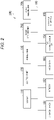
- FIG. 2 is a block diagram showing a hardware configuration of the image forming device 100 according to the embodiment.
- the image forming device 100 includes the display 110, the control panel 120, the printer unit 130, a paper feeding unit 205, a storage device 151, a memory 152, a processor 153, a wireless tag communication unit 154, an external interface 155, and the image reading unit 200.
- the display 110, the control panel 120, the printer unit 130, and the image reading unit 200 have been described above, and thus the description thereof will be omitted.
- the paper feeding unit 205 is a mechanism that feeds sheets placed in the sheet storage unit 140 and a manual feed tray described later to the printer unit 130.
- the storage device 151, the memory 152, the processor 153, the wireless tag communication unit 154, and the external interface 155 will be described.
- the functional units are connected via a system bus 160 in a data communicable manner.
- the storage device 151 is, for example, a hard disk drive or a solid state drive (SSD), and stores various kinds of data.
- the various kinds of data are a print job received from an external communication device and a software program for controlling an operation of each functional unit of the image forming device 100.
- the print job may be a job related to double-sided printing or a job related to printing of a plurality of sheets.
- the print job may include image information related to an image to be printed on the sheet.
- the memory 152 temporarily stores data used by each functional unit provided in the image forming device 100.
- the memory 152 is a random access memory (RAM), for example.
- the memory 152 may store digital data generated by the image reading unit 200.
- the memory 152 may temporarily store the print job being performed by the printer unit 130 and writing information to be written to the wireless tag.
- the processor 153 controls the operation of each functional unit of the image forming device 100.
- the processor 153 executes the processing by loading the software program stored in the storage device 151 into the memory 152, and executing the software program.
- specific processing of the processor 153 will be described with an example.
- the processor 153 controls printing on a sheet with a wireless tag based on a print job received via the external communication device or the control panel 120. Upon receiving the print job related to the sheet with the wireless tag, the processor 153 acquires write information specified in the print job and image information associated with the write information from, for example, a write information server not shown.
- the image information associated with the written information is information related to the image to be formed on the sheet. The image information does not necessarily have to be associated with the written information. In this case, the image information may be included in the print job.
- the processor 153 controls the paper feeding unit 205. The paper feeding unit 205 feeds the sheet with the wireless tag.
- the processor 153 controls the printer unit 130.
- the printer unit 130 forms an image indicated by the image information on the sheet.
- the sheet on which the image is formed is discharged to the paper discharge unit 210.
- the processor 153 controls the wireless tag communication unit 154.
- the wireless tag communication unit 154 includes an arithmetic device and a storage device.
- the wireless tag communication unit 154 writes information to the wireless tag provided on the sheet. Further, the wireless tag communication unit 154 reads information from the wireless tag provided on the sheet.
- the wireless tag communication unit 154 reads, for example, identification information (for example, Unique Identifier (UID)) that uniquely identifies the wireless tag.
- identification information for example, Unique Identifier (UID)
- Data transmission/reception with another device is performed via the external interface 155.
- the other device is, for example, an information processing device such as a personal computer, a tablet computer, or a smart device.
- the external interface 155 operates as an input interface and receives data or an instruction transmitted from the other device.
- the instruction transmitted from the other device is the print job or the like.
- the data transmitted from the other device is the write information, the image information associated with the write information, and the like.
- the external interface 155 operates as an output interface and transmits data to the other device.
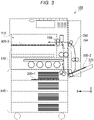
- FIG. 3 is a diagram showing an internal configuration of the image forming device 100. Further, FIG. 3 shows an example of the placement unit and an example of the conductor in the internal configuration. FIG. 3 newly shows a manual feed tray 220 and conductors 300-1, 300-2, and 300-3. The conductors 300-1, 300-2, and 300-3 are expressed as a conductor 300 when not distinguished from each other.
- the sheet storage unit 140, the manual feed tray 220, and the paper discharge unit 210 are taken as examples of the placement unit.
- the sheet storage unit 140 and the manual feed tray 220 are examples of the placement unit in which the sheet before the image is formed thereon is placed.
- the paper discharge unit 210 is an example of the placement unit in which the sheet after the image is formed thereon is placed.
- a communication range of the wireless tag communication unit 154 extends to the sheet storage unit 140, the manual feed tray 220, and the paper discharge unit 210. Therefore, in the present embodiment, by providing the conductor on the placement unit, communication between the wireless tag attached to the sheet placed on the placement unit and the wireless tag communication unit 154 is hindered. Specifically, when the sheet is placed on the conductor, impedance of the wireless tag attached to the sheet decreases, so that the communication is difficult.
- the conductor 300 is a material that easily conducts electricity, such as aluminum. Further, the conductor 300 shown in FIG. 3 is formed in a plate shape. In FIG. 3 , a side surface of the plate-shaped conductor 300 is drawn.
- the conductor 300-1 is provided in an uppermost paper feed cassette of the sheet storage unit 140.
- the conductor 300-1 hinders communication between the wireless tag attached to the sheet placed in the uppermost paper cassette and the wireless tag communication unit 154. Even if only one sheet is placed in the uppermost paper cassette, the conductor 300-1 also hinders the communication between the wireless tag attached to the sheet and the wireless tag communication unit 154.
- the conductor is provided in the uppermost paper cassette as an example, however, the conductor may be provided in another paper cassette.
- the conductor 300-2 is provided in the manual feed tray 220.
- the conductor 300-2 hinders communication between the wireless tag attached to the sheet placed in the manual feed tray 220 and the wireless tag communication unit 154. Even if only one sheet is placed on the manual feed tray 220, the conductor 300-2 also hinders the communication between the wireless tag attached to the sheet and the wireless tag communication unit 154.
- the conductor 300-3 is provided on the paper discharge unit 210.
- the conductor 300-3 hinders communication between the wireless tag attached to the sheet placed on the paper discharge unit 210 and the wireless tag communication unit 154. Even if only one sheet is placed on the paper discharge unit 210, the conductor 300-3 also hinders the communication between the wireless tag attached to the sheet and the wireless tag communication unit 154.
- the sheet to be discharged to the paper discharge unit 210 is discharged by paper discharge rollers 156. A paper discharge position of the sheet may vary depending on paper discharge momentum. Therefore, the conductor 300-3 is provided to cover the entire paper discharge unit 210.
- a direction toward the left is set as a Y-direction
- a direction from front to back is set as an X-direction.
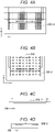
- FIGS. 4A, 4B, 4C, and 4D are views showing an installation example of the conductor 300-2 in the manual feed tray 220.
- FIGS. 4A and 4B are views of the manual feed tray 220 as seen from above.
- FIG. 4C is a view of the manual feed tray 220 as seen from front to back in the Y-direction.
- FIG. 4D is a view of the manual feed tray 220 as seen from back to front in the X-direction.
- a size of the conductor 300-2 is large enough to cover an entire sheet with a maximum sheet size on which an image can be formed by the image forming device 100. As a result, the conductor 300-2 can hinder the communication regardless of the sheet size.
- the conductor 300-2 shown in FIG. 4B is in a shape in which a portion of a region 310 is cut off, which is to prevent a paper feed roller for feeding the sheet and the conductor 300-2 from coming into contact with each other when the paper feed roller is provided in the region 310.
- a recess is prepared for providing the conductor 300-2 in the manual feed tray 220, and the conductor 300-2 is inserted in this recess, and thus the conductor 300-2 is provided such that a sheet placement surface is flat.
- FIG. 5 is a view showing an installation example of the conductor 300-1 in the sheet storage unit 140.
- the size of the conductor 300-1 is large enough to cover the entire sheet with the maximum sheet size on which an image can be formed by the image forming device 100. As a result, the conductor 300-1 can hinder the communication regardless of the sheet size.
- a metal plate for feeding paper is provided in the paper feed cassette of the sheet storage unit 140.
- the conductor 300-1 may be provided to cover the region in which the metal plate is not present.
- the conductor 300 is large enough to cover the entire sheet, and thus is always provided at a position in which the conductor overlaps with the wireless tag.
- the size of the conductor does not have to be large enough to cover the entire sheet with the maximum sheet size.
- a user may use only A4 size sheets and not use A3 size sheets.
- it is predetermined that a sheet with a size smaller than the maximum sheet size will be used, and when the position of the wireless tag on the sheet is unknown, a conductor that is large enough to cover the entire sheet with a sheet size to be used may be provided. That is, a conductor with a size corresponding to a sheet size used by a user may be provided. In this way, it is unnecessary to provide a conductor with an unnecessarily large size, and the cost of the conductor can be reduced.
- the conductor 300 may be provided to cover the region to which the wireless tag is attached instead of the entire sheet.
- FIG. 6 is a view showing an example of providing the conductor 300 to cover the position to which the wireless tag is attached instead of the entire sheet.
- regions 330 are defined as regions to each of which the wireless tag attached to the sheet is attached.
- the conductor 300-1 may be provided to cover the region 330. In this case, the conductor 300-1 can also hinder the communication with the wireless tag communication unit 154.
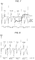
- FIG. 7 is a diagram showing RSSI before the conductor 300 is provided.
- FIG. 8 is a diagram showing RSSI after the conductor 300 is provided. Both FIGS. 7 and 8 show RSSI from when five sheets are placed in the sheet storage unit 140 to when one sheet is conveyed each time from a first sheet to a fourth sheet and an image is formed. Further, only one sheet is placed in the manual feed tray 220.
- FIG. 7 it is shown that only a signal from a RFID is received from a wireless tag attached to each of the first to third sheets. However, by conveying the fourth sheet, only the fifth sheet is placed in the sheet storage unit 140. As a result, a radio wave from the wireless tag attached to the fifth sheet is also received, so that the wireless tag communication unit 154 cannot distinguish between the fourth sheet and the fifth sheet. Thus, the wireless tag communication unit 154 may incorrectly write the write information to the wireless tag attached to the fifth sheet. A signal is received from the sheet placed in the manual feed tray 220 with almost constant radio field strength, and thus in this case as well, the write information may be incorrectly written on the wireless tag attached to the sheet placed in the manual feed tray 220.
- the sheet storage unit 140, the manual feed tray 220, and the paper discharge unit 210 are mentioned as the placement unit in which the conductor 300 is provided, but the conductor 300 may not be provided in all of these parts.
- a first configuration A the conductor 300 is provided in a placement unit in which a sheet before information is written to a wireless tag thereof by the wireless tag communication unit 154 is placed, but is not provided in a placement unit in which a sheet after information is written to a wireless tag thereof by the wireless tag communication unit 154 is placed.
- the placement unit in which the sheet before the information is written to the wireless tag thereof is placed is the sheet storage unit 140 or the manual feed tray 220.
- the placement unit in which the sheet after the information is written to the wireless tag thereof is placed is the paper discharge unit 210.
- the conductor 300 is provided in the placement unit in which a sheet provided with a wireless tag whose identification information that can uniquely identify the wireless tag by the wireless tag communication unit 154 is unknown is placed, but is not provided in the placement unit in which a sheet provided with a wireless tag whose identification information is known is placed.
- the wireless tag communication unit 154 acquires identification information from the wireless tag when writing the write information. Therefore, the configurations A and B can be implemented by the wireless tag communication unit 154 storing identification information of a wireless tag, to which the write information is written, in an own storage device.
- the placement unit in which a sheet provided with a wireless tag... unknown is placed in the configuration B is the sheet storage unit 140 or the manual feed tray 220.
- the placement unit in which a sheet provided with a wireless tag whose identification information is known is placed is the paper discharge unit 210.
- the wireless tag communication unit 154 receives signals from the wireless tag which is attached to the sheet being conveyed and to which the written information is not written and the wireless tag to which the written information is written. In this case, the wireless tag communication unit 154 writes by designating not the stored identification information (known identification information) but the un-stored identification information, that is, unknown identification information. As a result, the wireless tag to which the write information is written can be excluded, so that the write information can be prevented from being incorrectly written to the non-target wireless tag.
- the paper discharge position of the sheet discharged to the paper discharge unit 210 varies, but for example, by providing a positioning mechanism, the sheets can be discharged such that there is no variation.
- the wireless tags overlap, which makes communication difficult. Therefore, when the sheets are discharged such that there is no variation in the paper discharge position, it is sufficient for the wireless tag communication unit 154 to only store the identification information of the wireless tag attached to the first sheet.
- the information can be prevented from being incorrectly written to the non-target wireless tag.
Landscapes
- Engineering & Computer Science (AREA)
- Physics & Mathematics (AREA)
- General Physics & Mathematics (AREA)
- Multimedia (AREA)
- Signal Processing (AREA)
- Computer Networks & Wireless Communication (AREA)
- Theoretical Computer Science (AREA)
- Microelectronics & Electronic Packaging (AREA)
- Toxicology (AREA)
- Health & Medical Sciences (AREA)
- Computer Security & Cryptography (AREA)
- General Engineering & Computer Science (AREA)
- Computer Hardware Design (AREA)
- Electromagnetism (AREA)
- General Health & Medical Sciences (AREA)
- Artificial Intelligence (AREA)
- Computer Vision & Pattern Recognition (AREA)
- Facsimiles In General (AREA)
- Control Or Security For Electrophotography (AREA)
- Electrophotography Configuration And Component (AREA)
- Near-Field Transmission Systems (AREA)
Abstract
Description
- This application is based upon and claims the benefit of priority from
Japanese Patent Application No. 2021-085298, filed on May 20, 2021 - Embodiments described herein relates to an image forming device.
- There is an image forming device that writes on a wireless tag and forms an image on a sheet with the wireless tag using a radio frequency identifier (RFID) technique. When a wireless tag to be written (hereinafter, referred to as "target tag") passes through a conveying path, the image forming device writes information to the target tag by emitting a radio wave from an antenna to the target tag.
- Generally, when a plurality of sheets are placed on a placement unit such as a tray or a sheet feeding cassette on which sheets can be placed, wireless tags are overlapped. It is difficult for the overlapped wireless tags to receive the radio wave due to the overlapping. Therefore, the image forming device cannot communicate with the overlapped wireless tags. Meanwhile, the image forming device can communicate with a non-overlapped wireless tag such as a wireless tag passing through the conveying path. There is a technique of determining whether or not a tag is the target tag based on strength (received signal strength indication (RSSI)) of a radio signal transmitted from the wireless tag by using this property and writing information to the target tag.
- However, for example, when only one sheet remains in the tray, the wireless tag attached to the sheet is not overlapped. Therefore, the image forming device receives not only the radio wave from the wireless tag that is being conveyed but also the radio wave from the wireless tag attached to the sheet remaining in the tray. In this case, it is difficult for the image forming device to distinguish between the wireless tag attached to the sheet that is being conveyed and the wireless tag attached to the sheet remaining in the tray. As a result, the image forming device may incorrectly write the information to the wireless tag other than the target tag.
- One of the objects of the present invention is to improve prior art techniques and overcome at least some of the prior art problems as for instance above illustrated.
- According to a first aspect of the invention, it is provided an image forming device, comprising a placement component configured to accommodate a sheet provided with a wireless tag; a wireless tag communication writer configured to write information to the wireless tag provided on the sheet; and a conductor provided in the placement component, the conductor configured to hinder communication between the wireless tag communication writer and the wireless tag.
- Optionally, in the image forming device according to the first aspect of the invention, the conductor is provided at a position at which the conductor overlaps with the wireless tag.
- Optionally, in the image forming device according to the first aspect of the invention, the conductor is provided in a placement component in which a sheet before information is written to the wireless tag thereof by the wireless tag communication writer is placed, but is not provided in a placement component in which a sheet after information is written to the wireless tag thereof by the wireless tag communication writer is placed.
- Optionally, in the image forming device according to the first aspect of the invention, the conductor is provided in a placement component in which a sheet provided with the wireless tag whose identification information for uniquely identifying the wireless tag by the wireless tag communication writer is unknown is placed, but is not provided in a placement component in which a sheet provided with the wireless tag whose identification information is known is placed.
- Optionally, in the image forming device according to the first aspect of the invention, a sheet is placed in the placement component before an image is formed thereon, or a sheet is placed in the placement component after an image is formed thereon.
- Optionally, the image forming device according to the first aspect of the invention further comprises a conveying path through which passes the wireless tag to be written and in which the wireless tag communication writer writes information to the wireless tag by emitting a radio wave from an antenna.
- Optionally, in the image forming device according to the first aspect of the invention, the conductor is larger than the sheet.
- Optionally, in the image forming device according to the first aspect of the invention, the conductor is larger than the wireless tag communication writer.
- Optionally, the image forming device according to the first aspect of the invention further comprises two or more conductors.
- Optionally, the image forming device according to the first aspect of the invention further comprises comprising three or more conductors.
- According to a second aspect of the invention, it is provided an apparatus to reduce unintended RFID writing, comprising a placement component configured to accommodate a sheet provided with an RFID tag; a wireless tag communication writer configured to write information to the RFID tag provided on the sheet; and a conductor provided in the placement component, the conductor configured to hinder communication between the wireless tag communication writer and the RFID tag.
- Optionally, in the apparatus according to the second aspect of the invention, the conductor is provided at a position at which the conductor overlaps with the RFID tag.
- Optionally, in the apparatus according to the second aspect of the invention, the conductor is provided in a placement component in which a sheet before information is written to the RFID tag thereof by the wireless tag communication writer is placed, but is not provided in a placement component in which a sheet after information is written to the RFID tag thereof by the wireless tag communication writer is placed.
- Optionally, in the apparatus according to the second aspect of the invention, the conductor is provided in a placement component in which a sheet provided with the RFID tag whose identification information for uniquely identifying the RFID tag by the wireless tag communication writer is unknown is placed, but is not provided in a placement component in which a sheet provided with the RFID tag whose identification information is known is placed.
- Optionally, in the apparatus according to the second aspect of the invention, a sheet is placed in the placement component before an image is formed thereon, or a sheet is placed in the placement component after an image is formed thereon.
- Optionally, in the apparatus according to the second aspect of the invention, the conductor is larger than the sheet.
- Optionally, in the apparatus according to the second aspect of the invention, the conductor is larger than the wireless tag communication writer.
- Optionally, the apparatus according to the second aspect of the invention further comprises two or more conductors.
- Optionally, the apparatus according to the second aspect of the invention further comprises three or more conductors.
- According to a third aspect of the invention, it is provided a method of mitigating unintended wireless tag writing in an image forming device, comprising accommodating a sheet provided with a wireless tag on a placement component; configured to emitting write information from a wireless tag communication writer in the image forming device; and preventing communication between the wireless tag communication writer and the wireless tag when the sheet with the wireless tag is positioned on a placement component using a conductor provided in association with the placement component.
-
-
FIG. 1 is an external view showing an example of an overall configuration of an image forming device according to an embodiment. -
FIG. 2 is a block diagram showing a hardware configuration. -
FIG. 3 is a diagram showing a specific example of an internal configuration. -
FIG. 4A is a view of a manual feed tray as seen from above. -
FIG. 4B is a view of the manual feed tray as seen from above. -
FIG. 4C is a view of the manual feed tray as seen from front to back in a Y-direction. -
FIG. 4D is a view of the manual feed tray as seen from back to front in an X-direction. -
FIG. 5 is a view showing an installation example of a conductor in a sheet storage unit. -
FIG. 6 is a view showing an example of providing a conductor 300 to cover a position to which a wireless tag is attached. -
FIG. 7 is a diagram showing RSSI before the conductor is provided. -
FIG. 8 is a diagram showing RSSI after the conductor is provided. - In general, according to one embodiment, there is provided an image forming device that prevents incorrectly writing information to a non-target wireless tag.
- An image forming device according to an embodiment includes a placement unit, a wireless tag communication unit, and a conductor. A sheet provided with a wireless tag can be placed in the placement unit. The wireless tag communication unit can write information to the wireless tag provided on the sheet. The conductor is provided in the placement unit and hinders communication between the wireless tag communication unit and the wireless tag.
- In an image forming device of an embodiment, information is prevented from being incorrectly written to a non-target wireless tag. Hereinafter, the image forming device of the embodiment will be described in detail.
-
FIG. 1 is an external view showing an example of an overall configuration of animage forming device 100 according to the embodiment. Theimage forming device 100 is, for example, a multifunction device. Theimage forming device 100 includes adisplay 110, acontrol panel 120, aprinter unit 130, asheet storage unit 140, and animage reading unit 200. Theprinter unit 130 of theimage forming device 100 may be an electrophotographic type device that fixes a toner image, or an inkjet type device. - The
image forming device 100 forms an image on a sheet by using a developer such as toner. The sheet is, for example, paper or label paper. The sheet may be a sheet to which a wireless tag is attached. The sheet may be any material as long as theimage forming device 100 can form an image on a surface thereof. As the sheet to which the wireless tag is attached, the wireless tag may be attached to the surface of the sheet, or the wireless tag may be embedded inside the sheet. The wireless tag in the present embodiment is a wireless tag using a radio frequency identifier (RFID) technique, and is also called an RF tag. - The
display 110 is an image display device such as a liquid crystal display or an organic electro luminescence (EL) display. Thedisplay 110 displays various kinds of information related to theimage forming device 100. - The
control panel 120 includes a plurality of buttons. Thecontrol panel 120 receives an operation of a user. Thecontrol panel 120 outputs a signal corresponding to the operation performed by the user to a control unit of theimage forming device 100. Thedisplay 110 and thecontrol panel 120 may be configured as an integrated touch panel. - The
printer unit 130 forms an image on the sheet based on image information generated by theimage reading unit 200 or image information received via a communication path. Theprinter unit 130 forms the image by, for example, the following processing. Theprinter unit 130 forms an electrostatic latent image on a photoconductor drum based on the image information. Theprinter unit 130 forms a visible image by making the developer adhere to the electrostatic latent image. The toner is a specific example of the developer. Theprinter unit 130 transfers the visible image to the sheet. Theprinter unit 130 fixes the visible image on the sheet by heating and pressurizing the sheet. The sheet on which the image is formed may be a sheet stored in thesheet storage unit 140 or a hand-pointed sheet. The sheet on which the image is formed is discharged to apaper discharge unit 210. - The
sheet storage unit 140 stores a sheet used for image formation in theprinter unit 130. In the present embodiment, thesheet storage unit 140 is provided with four paper feed cassettes. Theimage reading unit 200 reads the image information to be read as an intensity of light. Theimage reading unit 200 records the read image information. The recorded image information may be transmitted to another information processing device through a network. The recorded image information may be used to form an image on the sheet by theprinter unit 130. -
FIG. 2 is a block diagram showing a hardware configuration of theimage forming device 100 according to the embodiment. Theimage forming device 100 includes thedisplay 110, thecontrol panel 120, theprinter unit 130, apaper feeding unit 205, astorage device 151, amemory 152, aprocessor 153, a wirelesstag communication unit 154, anexternal interface 155, and theimage reading unit 200. Thedisplay 110, thecontrol panel 120, theprinter unit 130, and theimage reading unit 200 have been described above, and thus the description thereof will be omitted. Thepaper feeding unit 205 is a mechanism that feeds sheets placed in thesheet storage unit 140 and a manual feed tray described later to theprinter unit 130. Hereinafter, thestorage device 151, thememory 152, theprocessor 153, the wirelesstag communication unit 154, and theexternal interface 155 will be described. The functional units are connected via asystem bus 160 in a data communicable manner. - The
storage device 151 is, for example, a hard disk drive or a solid state drive (SSD), and stores various kinds of data. The various kinds of data are a print job received from an external communication device and a software program for controlling an operation of each functional unit of theimage forming device 100. The print job may be a job related to double-sided printing or a job related to printing of a plurality of sheets. The print job may include image information related to an image to be printed on the sheet. - The
memory 152 temporarily stores data used by each functional unit provided in theimage forming device 100. Thememory 152 is a random access memory (RAM), for example. Thememory 152 may store digital data generated by theimage reading unit 200. Thememory 152 may temporarily store the print job being performed by theprinter unit 130 and writing information to be written to the wireless tag. - The
processor 153 controls the operation of each functional unit of theimage forming device 100. Theprocessor 153 executes the processing by loading the software program stored in thestorage device 151 into thememory 152, and executing the software program. Here, specific processing of theprocessor 153 will be described with an example. - The
processor 153 controls printing on a sheet with a wireless tag based on a print job received via the external communication device or thecontrol panel 120. Upon receiving the print job related to the sheet with the wireless tag, theprocessor 153 acquires write information specified in the print job and image information associated with the write information from, for example, a write information server not shown. The image information associated with the written information is information related to the image to be formed on the sheet. The image information does not necessarily have to be associated with the written information. In this case, the image information may be included in the print job. Theprocessor 153 controls thepaper feeding unit 205. Thepaper feeding unit 205 feeds the sheet with the wireless tag. - The
processor 153 controls theprinter unit 130. Theprinter unit 130 forms an image indicated by the image information on the sheet. The sheet on which the image is formed is discharged to thepaper discharge unit 210. Theprocessor 153 controls the wirelesstag communication unit 154. The wirelesstag communication unit 154 includes an arithmetic device and a storage device. The wirelesstag communication unit 154 writes information to the wireless tag provided on the sheet. Further, the wirelesstag communication unit 154 reads information from the wireless tag provided on the sheet. The wirelesstag communication unit 154 reads, for example, identification information (for example, Unique Identifier (UID)) that uniquely identifies the wireless tag. - Data transmission/reception with another device is performed via the
external interface 155. Here, the other device is, for example, an information processing device such as a personal computer, a tablet computer, or a smart device. Theexternal interface 155 operates as an input interface and receives data or an instruction transmitted from the other device. The instruction transmitted from the other device is the print job or the like. The data transmitted from the other device is the write information, the image information associated with the write information, and the like. Further, theexternal interface 155 operates as an output interface and transmits data to the other device. -
FIG. 3 is a diagram showing an internal configuration of theimage forming device 100. Further,FIG. 3 shows an example of the placement unit and an example of the conductor in the internal configuration.FIG. 3 newly shows amanual feed tray 220 and conductors 300-1, 300-2, and 300-3. The conductors 300-1, 300-2, and 300-3 are expressed as a conductor 300 when not distinguished from each other. In the present embodiment, thesheet storage unit 140, themanual feed tray 220, and thepaper discharge unit 210 are taken as examples of the placement unit. Thesheet storage unit 140 and themanual feed tray 220 are examples of the placement unit in which the sheet before the image is formed thereon is placed. Thepaper discharge unit 210 is an example of the placement unit in which the sheet after the image is formed thereon is placed. - A communication range of the wireless
tag communication unit 154 extends to thesheet storage unit 140, themanual feed tray 220, and thepaper discharge unit 210. Therefore, in the present embodiment, by providing the conductor on the placement unit, communication between the wireless tag attached to the sheet placed on the placement unit and the wirelesstag communication unit 154 is hindered. Specifically, when the sheet is placed on the conductor, impedance of the wireless tag attached to the sheet decreases, so that the communication is difficult. The conductor 300 is a material that easily conducts electricity, such as aluminum. Further, the conductor 300 shown inFIG. 3 is formed in a plate shape. InFIG. 3 , a side surface of the plate-shaped conductor 300 is drawn. - The conductor 300-1 is provided in an uppermost paper feed cassette of the
sheet storage unit 140. The conductor 300-1 hinders communication between the wireless tag attached to the sheet placed in the uppermost paper cassette and the wirelesstag communication unit 154. Even if only one sheet is placed in the uppermost paper cassette, the conductor 300-1 also hinders the communication between the wireless tag attached to the sheet and the wirelesstag communication unit 154. The conductor is provided in the uppermost paper cassette as an example, however, the conductor may be provided in another paper cassette. - The conductor 300-2 is provided in the
manual feed tray 220. The conductor 300-2 hinders communication between the wireless tag attached to the sheet placed in themanual feed tray 220 and the wirelesstag communication unit 154. Even if only one sheet is placed on themanual feed tray 220, the conductor 300-2 also hinders the communication between the wireless tag attached to the sheet and the wirelesstag communication unit 154. - The conductor 300-3 is provided on the
paper discharge unit 210. The conductor 300-3 hinders communication between the wireless tag attached to the sheet placed on thepaper discharge unit 210 and the wirelesstag communication unit 154. Even if only one sheet is placed on thepaper discharge unit 210, the conductor 300-3 also hinders the communication between the wireless tag attached to the sheet and the wirelesstag communication unit 154. The sheet to be discharged to thepaper discharge unit 210 is discharged bypaper discharge rollers 156. A paper discharge position of the sheet may vary depending on paper discharge momentum. Therefore, the conductor 300-3 is provided to cover the entirepaper discharge unit 210. - In
FIG. 3 described above, a direction toward the left is set as a Y-direction, and a direction from front to back is set as an X-direction. -
FIGS. 4A, 4B, 4C, and 4D are views showing an installation example of the conductor 300-2 in themanual feed tray 220.FIGS. 4A and 4B are views of themanual feed tray 220 as seen from above.FIG. 4C is a view of themanual feed tray 220 as seen from front to back in the Y-direction.FIG. 4D is a view of themanual feed tray 220 as seen from back to front in the X-direction. - As shown in
FIGS. 4A and 4B , a size of the conductor 300-2 is large enough to cover an entire sheet with a maximum sheet size on which an image can be formed by theimage forming device 100. As a result, the conductor 300-2 can hinder the communication regardless of the sheet size. The conductor 300-2 shown inFIG. 4B is in a shape in which a portion of aregion 310 is cut off, which is to prevent a paper feed roller for feeding the sheet and the conductor 300-2 from coming into contact with each other when the paper feed roller is provided in theregion 310. - As shown in
FIGS. 4C and 4D , a recess is prepared for providing the conductor 300-2 in themanual feed tray 220, and the conductor 300-2 is inserted in this recess, and thus the conductor 300-2 is provided such that a sheet placement surface is flat. -
FIG. 5 is a view showing an installation example of the conductor 300-1 in thesheet storage unit 140. The size of the conductor 300-1 is large enough to cover the entire sheet with the maximum sheet size on which an image can be formed by theimage forming device 100. As a result, the conductor 300-1 can hinder the communication regardless of the sheet size. A metal plate for feeding paper is provided in the paper feed cassette of thesheet storage unit 140. The conductor 300-1 may be provided to cover the region in which the metal plate is not present. - As described above, the conductor 300 is large enough to cover the entire sheet, and thus is always provided at a position in which the conductor overlaps with the wireless tag. The size of the conductor does not have to be large enough to cover the entire sheet with the maximum sheet size. For example, a user may use only A4 size sheets and not use A3 size sheets. In this way, it is predetermined that a sheet with a size smaller than the maximum sheet size will be used, and when the position of the wireless tag on the sheet is unknown, a conductor that is large enough to cover the entire sheet with a sheet size to be used may be provided. That is, a conductor with a size corresponding to a sheet size used by a user may be provided. In this way, it is unnecessary to provide a conductor with an unnecessarily large size, and the cost of the conductor can be reduced.
- When the position on the sheet to which the wireless tag is attached is predetermined, the conductor 300 may be provided to cover the region to which the wireless tag is attached instead of the entire sheet.
-
FIG. 6 is a view showing an example of providing the conductor 300 to cover the position to which the wireless tag is attached instead of the entire sheet. For example,regions 330 are defined as regions to each of which the wireless tag attached to the sheet is attached. The conductor 300-1 may be provided to cover theregion 330. In this case, the conductor 300-1 can also hinder the communication with the wirelesstag communication unit 154. - Next, experimental results of measuring received signal strength indication (RSSI) before and after the conductor 300 is provided will be introduced.
FIG. 7 is a diagram showing RSSI before the conductor 300 is provided.FIG. 8 is a diagram showing RSSI after the conductor 300 is provided. BothFIGS. 7 and 8 show RSSI from when five sheets are placed in thesheet storage unit 140 to when one sheet is conveyed each time from a first sheet to a fourth sheet and an image is formed. Further, only one sheet is placed in themanual feed tray 220. - Vertical axes of the graphs of
FIGS. 7 and 8 indicate RSSI, and horizontal axes indicate time. As shown inFIG. 7 , it is shown that only a signal from a RFID is received from a wireless tag attached to each of the first to third sheets. However, by conveying the fourth sheet, only the fifth sheet is placed in thesheet storage unit 140. As a result, a radio wave from the wireless tag attached to the fifth sheet is also received, so that the wirelesstag communication unit 154 cannot distinguish between the fourth sheet and the fifth sheet. Thus, the wirelesstag communication unit 154 may incorrectly write the write information to the wireless tag attached to the fifth sheet. A signal is received from the sheet placed in themanual feed tray 220 with almost constant radio field strength, and thus in this case as well, the write information may be incorrectly written on the wireless tag attached to the sheet placed in themanual feed tray 220. - Meanwhile, by providing the conductor 300, as shown in
FIG. 8 , only a signal from a RFID is received from the wireless tag attached to each of the first to third sheets. No signal is received from the wireless tag attached to the fifth sheet and the wireless tag attached to the sheet placed in themanual feed tray 220. Therefore, since the wirelesstag communication unit 154 does not make the sheets indistinguishable, information can be prevented from being incorrectly written to the non-target wireless tag. - In the above embodiment, the
sheet storage unit 140, themanual feed tray 220, and thepaper discharge unit 210 are mentioned as the placement unit in which the conductor 300 is provided, but the conductor 300 may not be provided in all of these parts. - Specifically, as a confirmation in which the conductor 300 is not provided in all of these parts, two configurations will be described specifically. In a first configuration A, the conductor 300 is provided in a placement unit in which a sheet before information is written to a wireless tag thereof by the wireless
tag communication unit 154 is placed, but is not provided in a placement unit in which a sheet after information is written to a wireless tag thereof by the wirelesstag communication unit 154 is placed. In the present embodiment, the placement unit in which the sheet before the information is written to the wireless tag thereof is placed is thesheet storage unit 140 or themanual feed tray 220. The placement unit in which the sheet after the information is written to the wireless tag thereof is placed is thepaper discharge unit 210. - In a second configuration B, the conductor 300 is provided in the placement unit in which a sheet provided with a wireless tag whose identification information that can uniquely identify the wireless tag by the wireless
tag communication unit 154 is unknown is placed, but is not provided in the placement unit in which a sheet provided with a wireless tag whose identification information is known is placed. - The wireless
tag communication unit 154 acquires identification information from the wireless tag when writing the write information. Therefore, the configurations A and B can be implemented by the wirelesstag communication unit 154 storing identification information of a wireless tag, to which the write information is written, in an own storage device. In this case, "the placement unit in which a sheet provided with a wireless tag... unknown is placed" in the configuration B is thesheet storage unit 140 or themanual feed tray 220. Further, "the placement unit in which a sheet provided with a wireless tag whose identification information is known is placed" in the configuration B is thepaper discharge unit 210. - It is assumed that the wireless
tag communication unit 154 receives signals from the wireless tag which is attached to the sheet being conveyed and to which the written information is not written and the wireless tag to which the written information is written. In this case, the wirelesstag communication unit 154 writes by designating not the stored identification information (known identification information) but the un-stored identification information, that is, unknown identification information. As a result, the wireless tag to which the write information is written can be excluded, so that the write information can be prevented from being incorrectly written to the non-target wireless tag. - As described above, the paper discharge position of the sheet discharged to the
paper discharge unit 210 varies, but for example, by providing a positioning mechanism, the sheets can be discharged such that there is no variation. In this case, when two or more sheets are discharged, the wireless tags overlap, which makes communication difficult. Therefore, when the sheets are discharged such that there is no variation in the paper discharge position, it is sufficient for the wirelesstag communication unit 154 to only store the identification information of the wireless tag attached to the first sheet. - According to the embodiment described above, since communication with the non-target wireless tag is hindered by providing the conductor in the placement unit, the information can be prevented from being incorrectly written to the non-target wireless tag.
- While certain embodiments have been described, these embodiments have been presented by way of example only, and are not intended to limit the scope of the disclosure. These embodiments can be carried out in various other forms, and various omissions, replacements, and modifications can be made thereto without departing from the scope of the disclosure as defined by the appended claims. These embodiments and modifications thereof are included in the scope of the disclosure, as well as in the scope of the disclosure described in the scope of claims and the equivalent scope thereof.
Claims (13)
- An image forming device, comprising:a placement component configured to accommodate a sheet provided with a wireless tag;a wireless tag communication writer configured to write information to the wireless tag provided on the sheet; anda conductor provided in the placement component, the conductor configured to hinder communication between the wireless tag communication writer and the wireless tag.
- A apparatus comprising:a placement component configured to accommodate a sheet provided with a wireless tag;a wireless tag communication writer configured to write information to the wireless tag provided on the sheet; anda conductor provided in the placement component, the conductor configured to hinder communication between the wireless tag communication writer and the wireless tag.
- The image forming device according to claim 1 or 2, wherein
the conductor is provided at a position at which the conductor overlaps with the wireless tag. - The image forming device according to any of claims 1 to 3, wherein
the conductor is provided in a placement component in which a sheet before information is written to the wireless tag thereof by the wireless tag communication writer is placed, but is not provided in a placement component in which a sheet after information is written to the wireless tag thereof by the wireless tag communication writer is placed. - The image forming device according to any of claims 1 to 4, wherein
the conductor is provided in a placement component in which a sheet provided with the wireless tag whose identification information for uniquely identifying the wireless tag by the wireless tag communication writer is unknown is placed, but is not provided in a placement component in which a sheet provided with the wireless tag whose identification information is known is placed. - The image forming device according to any of claims 1 to 5, wherein
a sheet is placed in the placement component before an image is formed thereon, or a sheet is placed in the placement component after an image is formed thereon. - The image forming device according to any of claims 1 to 6, further comprising:
a conveying path through which passes the wireless tag to be written and in which the wireless tag communication writer writes information to the wireless tag by emitting a radio wave from an antenna. - The image forming device according to any of claims 1 to 7, wherein
the conductor is larger than the sheet. - The image forming device according to any of claims 1 to 8, wherein
the conductor is larger than the wireless tag communication writer. - The image forming device according to any of claims 1 to 9, comprising two or more conductors.
- The image forming device according to any of claims 1 to 10, comprising three or more conductors.
- An apparatus according to any of claims 2 to 11, wherein the apparatus is to reduce united RFID writing and the wireless tag includes an RFID tag.
- A method of mitigating unintended wireless tag writing in an image forming device, comprising:accommodating a sheet provided with a wireless tag on a placement component;configured to emitting write information from a wireless tag communication writer in the image forming device; andpreventing communication between the wireless tag communication writer and the wireless tag when the sheet with the wireless tag is positioned on a placement component using a conductor provided in association with the placement component.
Applications Claiming Priority (1)
| Application Number | Priority Date | Filing Date | Title |
|---|---|---|---|
| JP2021085298A JP7701190B2 (en) | 2021-05-20 | 2021-05-20 | Image forming device |
Publications (2)
| Publication Number | Publication Date |
|---|---|
| EP4093007A1 true EP4093007A1 (en) | 2022-11-23 |
| EP4093007B1 EP4093007B1 (en) | 2024-03-27 |
Family
ID=80683089
Family Applications (1)
| Application Number | Title | Priority Date | Filing Date |
|---|---|---|---|
| EP22160434.1A Active EP4093007B1 (en) | 2021-05-20 | 2022-03-07 | Image forming device |
Country Status (4)
| Country | Link |
|---|---|
| US (2) | US11741321B2 (en) |
| EP (1) | EP4093007B1 (en) |
| JP (2) | JP7701190B2 (en) |
| CN (1) | CN115374891A (en) |
Cited By (1)
| Publication number | Priority date | Publication date | Assignee | Title |
|---|---|---|---|---|
| EP4485272A1 (en) * | 2023-06-27 | 2025-01-01 | Toshiba TEC Kabushiki Kaisha | Image forming apparatus |
Families Citing this family (4)
| Publication number | Priority date | Publication date | Assignee | Title |
|---|---|---|---|---|
| JP7701190B2 (en) * | 2021-05-20 | 2025-07-01 | 東芝テック株式会社 | Image forming device |
| JP7791692B2 (en) | 2021-11-01 | 2025-12-24 | 東芝テック株式会社 | Conductive sheet and sheet bundle package |
| JP7778537B2 (en) | 2021-11-11 | 2025-12-02 | 東芝テック株式会社 | Wireless tag communication device, image forming device, and program |
| JP2025109347A (en) * | 2024-01-12 | 2025-07-25 | 東芝テック株式会社 | Radio tag communication system |
Citations (3)
| Publication number | Priority date | Publication date | Assignee | Title |
|---|---|---|---|---|
| US20100110490A1 (en) * | 2008-10-31 | 2010-05-06 | Brother Kogyo Kabushiki Kaisha | Facsimile communication system |
| EP2192759A1 (en) * | 2008-11-26 | 2010-06-02 | Brother Kogyo Kabushiki Kaisha | Image-forming device |
| EP3709088A1 (en) * | 2019-03-15 | 2020-09-16 | Toshiba TEC Kabushiki Kaisha | Image forming apparatus and image forming method |
Family Cites Families (17)
| Publication number | Priority date | Publication date | Assignee | Title |
|---|---|---|---|---|
| JP3912031B2 (en) * | 2001-05-15 | 2007-05-09 | 株式会社デンソーウェーブ | Copy machines and facsimile machines |
| JP2004284066A (en) * | 2003-03-19 | 2004-10-14 | Ricoh Co Ltd | Printing equipment |
| US7463388B2 (en) * | 2003-05-29 | 2008-12-09 | Canon Kabushiki Kaisha | Image forming apparatus with control of image formation using read information |
| JP2007076065A (en) * | 2005-09-12 | 2007-03-29 | Ricoh Co Ltd | Image forming apparatus |
| JP4671121B2 (en) * | 2005-12-12 | 2011-04-13 | ブラザー工業株式会社 | Image forming apparatus |
| JP4959262B2 (en) | 2006-09-12 | 2012-06-20 | サトーホールディングス株式会社 | RFID printer |
| JP2010206323A (en) * | 2009-02-27 | 2010-09-16 | Toshiba Tec Corp | Rfid printer |
| CN204376890U (en) * | 2014-11-27 | 2015-06-03 | 龙尚科技(上海)有限公司 | A kind of wireless terminal module |
| US9818006B1 (en) * | 2016-05-12 | 2017-11-14 | Lexmark International, Inc. | RFID tag programming in a duplexer |
| EP3483658B1 (en) * | 2016-07-06 | 2021-07-21 | KYOCERA Document Solutions Inc. | Image formation apparatus, reader/writer, and coloring agent cartridge |
| JP2018097686A (en) * | 2016-12-14 | 2018-06-21 | 東芝テック株式会社 | Rfid reader and writer, and program |
| JP2018198036A (en) * | 2017-05-25 | 2018-12-13 | 東芝テック株式会社 | Label processor |
| US10255535B1 (en) * | 2017-12-07 | 2019-04-09 | Kabushiki Kaisha Toshiba | Image forming apparatus and control method |
| US10725409B1 (en) * | 2019-02-12 | 2020-07-28 | Toshiba Tec Kabushiki Kaisha | Fixing device, image forming apparatus and recording medium |
| JP2021039590A (en) | 2019-09-04 | 2021-03-11 | 東芝テック株式会社 | Wireless tag processing device and program |
| JP7496059B2 (en) * | 2020-06-01 | 2024-06-06 | 株式会社リコー | Image forming device |
| JP7701190B2 (en) * | 2021-05-20 | 2025-07-01 | 東芝テック株式会社 | Image forming device |
-
2021
- 2021-05-20 JP JP2021085298A patent/JP7701190B2/en active Active
- 2021-11-18 US US17/529,473 patent/US11741321B2/en active Active
-
2022
- 2022-02-09 CN CN202210122954.4A patent/CN115374891A/en active Pending
- 2022-03-07 EP EP22160434.1A patent/EP4093007B1/en active Active
-
2023
- 2023-07-14 US US18/352,292 patent/US12223381B2/en active Active
-
2025
- 2025-06-18 JP JP2025102560A patent/JP2025129170A/en active Pending
Patent Citations (3)
| Publication number | Priority date | Publication date | Assignee | Title |
|---|---|---|---|---|
| US20100110490A1 (en) * | 2008-10-31 | 2010-05-06 | Brother Kogyo Kabushiki Kaisha | Facsimile communication system |
| EP2192759A1 (en) * | 2008-11-26 | 2010-06-02 | Brother Kogyo Kabushiki Kaisha | Image-forming device |
| EP3709088A1 (en) * | 2019-03-15 | 2020-09-16 | Toshiba TEC Kabushiki Kaisha | Image forming apparatus and image forming method |
Cited By (1)
| Publication number | Priority date | Publication date | Assignee | Title |
|---|---|---|---|---|
| EP4485272A1 (en) * | 2023-06-27 | 2025-01-01 | Toshiba TEC Kabushiki Kaisha | Image forming apparatus |
Also Published As
| Publication number | Publication date |
|---|---|
| JP2022178472A (en) | 2022-12-02 |
| EP4093007B1 (en) | 2024-03-27 |
| US20230359838A1 (en) | 2023-11-09 |
| CN115374891A (en) | 2022-11-22 |
| US20220374620A1 (en) | 2022-11-24 |
| JP2025129170A (en) | 2025-09-04 |
| US11741321B2 (en) | 2023-08-29 |
| JP7701190B2 (en) | 2025-07-01 |
| US12223381B2 (en) | 2025-02-11 |
Similar Documents
| Publication | Publication Date | Title |
|---|---|---|
| US11741321B2 (en) | Image forming device | |
| US11232338B2 (en) | Radio tag communication device, radio tag communication method, and image forming apparatus | |
| EP3709088A1 (en) | Image forming apparatus and image forming method | |
| US20080317479A1 (en) | Image Forming Apparatus | |
| US20240296303A1 (en) | Image forming apparatus and communication device | |
| US11457119B2 (en) | Image forming apparatus | |
| US20210289083A1 (en) | Image forming system and image forming method | |
| US12081707B2 (en) | Printer | |
| US20230325622A1 (en) | Image forming device and warning method | |
| EP4485272B1 (en) | Image forming apparatus | |
| US12341934B2 (en) | Wireless tag communication device, image forming apparatus, and method | |
| US20250383623A1 (en) | Image forming apparatus | |
| US12212723B2 (en) | Image forming apparatus and control method using image forming data file | |
| US20250251695A1 (en) | Image forming apparatus | |
| JP2008003227A (en) | Image forming apparatus | |
| US20230043412A1 (en) | Image forming apparatus | |
| JP2025042411A (en) | Image forming device | |
| CN119165749A (en) | Image forming device |
Legal Events
| Date | Code | Title | Description |
|---|---|---|---|
| PUAI | Public reference made under article 153(3) epc to a published international application that has entered the european phase |
Free format text: ORIGINAL CODE: 0009012 |
|
| STAA | Information on the status of an ep patent application or granted ep patent |
Free format text: STATUS: THE APPLICATION HAS BEEN PUBLISHED |
|
| AK | Designated contracting states |
Kind code of ref document: A1 Designated state(s): AL AT BE BG CH CY CZ DE DK EE ES FI FR GB GR HR HU IE IS IT LI LT LU LV MC MK MT NL NO PL PT RO RS SE SI SK SM TR |
|
| STAA | Information on the status of an ep patent application or granted ep patent |
Free format text: STATUS: REQUEST FOR EXAMINATION WAS MADE |
|
| 17P | Request for examination filed |
Effective date: 20230516 |
|
| RBV | Designated contracting states (corrected) |
Designated state(s): AL AT BE BG CH CY CZ DE DK EE ES FI FR GB GR HR HU IE IS IT LI LT LU LV MC MK MT NL NO PL PT RO RS SE SI SK SM TR |
|
| RIC1 | Information provided on ipc code assigned before grant |
Ipc: H04N 1/32 20060101ALI20230928BHEP Ipc: H04N 1/00 20060101AFI20230928BHEP |
|
| GRAP | Despatch of communication of intention to grant a patent |
Free format text: ORIGINAL CODE: EPIDOSNIGR1 |
|
| STAA | Information on the status of an ep patent application or granted ep patent |
Free format text: STATUS: GRANT OF PATENT IS INTENDED |
|
| INTG | Intention to grant announced |
Effective date: 20231106 |
|
| GRAS | Grant fee paid |
Free format text: ORIGINAL CODE: EPIDOSNIGR3 |
|
| GRAA | (expected) grant |
Free format text: ORIGINAL CODE: 0009210 |
|
| STAA | Information on the status of an ep patent application or granted ep patent |
Free format text: STATUS: THE PATENT HAS BEEN GRANTED |
|
| AK | Designated contracting states |
Kind code of ref document: B1 Designated state(s): AL AT BE BG CH CY CZ DE DK EE ES FI FR GB GR HR HU IE IS IT LI LT LU LV MC MK MT NL NO PL PT RO RS SE SI SK SM TR |
|
| REG | Reference to a national code |
Ref country code: GB Ref legal event code: FG4D |
|
| REG | Reference to a national code |
Ref country code: CH Ref legal event code: EP |
|
| REG | Reference to a national code |
Ref country code: DE Ref legal event code: R096 Ref document number: 602022002502 Country of ref document: DE |
|
| REG | Reference to a national code |
Ref country code: IE Ref legal event code: FG4D |
|
| PG25 | Lapsed in a contracting state [announced via postgrant information from national office to epo] |
Ref country code: LT Free format text: LAPSE BECAUSE OF FAILURE TO SUBMIT A TRANSLATION OF THE DESCRIPTION OR TO PAY THE FEE WITHIN THE PRESCRIBED TIME-LIMIT Effective date: 20240327 |
|
| REG | Reference to a national code |
Ref country code: LT Ref legal event code: MG9D |
|
| PG25 | Lapsed in a contracting state [announced via postgrant information from national office to epo] |
Ref country code: GR Free format text: LAPSE BECAUSE OF FAILURE TO SUBMIT A TRANSLATION OF THE DESCRIPTION OR TO PAY THE FEE WITHIN THE PRESCRIBED TIME-LIMIT Effective date: 20240628 |
|
| PG25 | Lapsed in a contracting state [announced via postgrant information from national office to epo] |
Ref country code: HR Free format text: LAPSE BECAUSE OF FAILURE TO SUBMIT A TRANSLATION OF THE DESCRIPTION OR TO PAY THE FEE WITHIN THE PRESCRIBED TIME-LIMIT Effective date: 20240327 Ref country code: RS Free format text: LAPSE BECAUSE OF FAILURE TO SUBMIT A TRANSLATION OF THE DESCRIPTION OR TO PAY THE FEE WITHIN THE PRESCRIBED TIME-LIMIT Effective date: 20240627 |
|
| PG25 | Lapsed in a contracting state [announced via postgrant information from national office to epo] |
Ref country code: RS Free format text: LAPSE BECAUSE OF FAILURE TO SUBMIT A TRANSLATION OF THE DESCRIPTION OR TO PAY THE FEE WITHIN THE PRESCRIBED TIME-LIMIT Effective date: 20240627 Ref country code: NO Free format text: LAPSE BECAUSE OF FAILURE TO SUBMIT A TRANSLATION OF THE DESCRIPTION OR TO PAY THE FEE WITHIN THE PRESCRIBED TIME-LIMIT Effective date: 20240627 Ref country code: LT Free format text: LAPSE BECAUSE OF FAILURE TO SUBMIT A TRANSLATION OF THE DESCRIPTION OR TO PAY THE FEE WITHIN THE PRESCRIBED TIME-LIMIT Effective date: 20240327 Ref country code: HR Free format text: LAPSE BECAUSE OF FAILURE TO SUBMIT A TRANSLATION OF THE DESCRIPTION OR TO PAY THE FEE WITHIN THE PRESCRIBED TIME-LIMIT Effective date: 20240327 Ref country code: GR Free format text: LAPSE BECAUSE OF FAILURE TO SUBMIT A TRANSLATION OF THE DESCRIPTION OR TO PAY THE FEE WITHIN THE PRESCRIBED TIME-LIMIT Effective date: 20240628 Ref country code: FI Free format text: LAPSE BECAUSE OF FAILURE TO SUBMIT A TRANSLATION OF THE DESCRIPTION OR TO PAY THE FEE WITHIN THE PRESCRIBED TIME-LIMIT Effective date: 20240327 Ref country code: BG Free format text: LAPSE BECAUSE OF FAILURE TO SUBMIT A TRANSLATION OF THE DESCRIPTION OR TO PAY THE FEE WITHIN THE PRESCRIBED TIME-LIMIT Effective date: 20240327 |
|
| REG | Reference to a national code |
Ref country code: NL Ref legal event code: MP Effective date: 20240327 |
|
| PG25 | Lapsed in a contracting state [announced via postgrant information from national office to epo] |
Ref country code: SE Free format text: LAPSE BECAUSE OF FAILURE TO SUBMIT A TRANSLATION OF THE DESCRIPTION OR TO PAY THE FEE WITHIN THE PRESCRIBED TIME-LIMIT Effective date: 20240327 Ref country code: LV Free format text: LAPSE BECAUSE OF FAILURE TO SUBMIT A TRANSLATION OF THE DESCRIPTION OR TO PAY THE FEE WITHIN THE PRESCRIBED TIME-LIMIT Effective date: 20240327 |
|
| PG25 | Lapsed in a contracting state [announced via postgrant information from national office to epo] |
Ref country code: NL Free format text: LAPSE BECAUSE OF FAILURE TO SUBMIT A TRANSLATION OF THE DESCRIPTION OR TO PAY THE FEE WITHIN THE PRESCRIBED TIME-LIMIT Effective date: 20240327 |
|
| REG | Reference to a national code |
Ref country code: AT Ref legal event code: MK05 Ref document number: 1671006 Country of ref document: AT Kind code of ref document: T Effective date: 20240327 |
|
| PG25 | Lapsed in a contracting state [announced via postgrant information from national office to epo] |
Ref country code: NL Free format text: LAPSE BECAUSE OF FAILURE TO SUBMIT A TRANSLATION OF THE DESCRIPTION OR TO PAY THE FEE WITHIN THE PRESCRIBED TIME-LIMIT Effective date: 20240327 |
|
| PG25 | Lapsed in a contracting state [announced via postgrant information from national office to epo] |
Ref country code: IS Free format text: LAPSE BECAUSE OF FAILURE TO SUBMIT A TRANSLATION OF THE DESCRIPTION OR TO PAY THE FEE WITHIN THE PRESCRIBED TIME-LIMIT Effective date: 20240727 |
|
| PG25 | Lapsed in a contracting state [announced via postgrant information from national office to epo] |
Ref country code: PT Free format text: LAPSE BECAUSE OF FAILURE TO SUBMIT A TRANSLATION OF THE DESCRIPTION OR TO PAY THE FEE WITHIN THE PRESCRIBED TIME-LIMIT Effective date: 20240729 Ref country code: SM Free format text: LAPSE BECAUSE OF FAILURE TO SUBMIT A TRANSLATION OF THE DESCRIPTION OR TO PAY THE FEE WITHIN THE PRESCRIBED TIME-LIMIT Effective date: 20240327 |
|
| PG25 | Lapsed in a contracting state [announced via postgrant information from national office to epo] |
Ref country code: ES Free format text: LAPSE BECAUSE OF FAILURE TO SUBMIT A TRANSLATION OF THE DESCRIPTION OR TO PAY THE FEE WITHIN THE PRESCRIBED TIME-LIMIT Effective date: 20240327 |
|
| PG25 | Lapsed in a contracting state [announced via postgrant information from national office to epo] |
Ref country code: EE Free format text: LAPSE BECAUSE OF FAILURE TO SUBMIT A TRANSLATION OF THE DESCRIPTION OR TO PAY THE FEE WITHIN THE PRESCRIBED TIME-LIMIT Effective date: 20240327 Ref country code: CZ Free format text: LAPSE BECAUSE OF FAILURE TO SUBMIT A TRANSLATION OF THE DESCRIPTION OR TO PAY THE FEE WITHIN THE PRESCRIBED TIME-LIMIT Effective date: 20240327 |
|
| PG25 | Lapsed in a contracting state [announced via postgrant information from national office to epo] |
Ref country code: AT Free format text: LAPSE BECAUSE OF FAILURE TO SUBMIT A TRANSLATION OF THE DESCRIPTION OR TO PAY THE FEE WITHIN THE PRESCRIBED TIME-LIMIT Effective date: 20240327 |
|
| PG25 | Lapsed in a contracting state [announced via postgrant information from national office to epo] |
Ref country code: PL Free format text: LAPSE BECAUSE OF FAILURE TO SUBMIT A TRANSLATION OF THE DESCRIPTION OR TO PAY THE FEE WITHIN THE PRESCRIBED TIME-LIMIT Effective date: 20240327 |
|
| PG25 | Lapsed in a contracting state [announced via postgrant information from national office to epo] |
Ref country code: SK Free format text: LAPSE BECAUSE OF FAILURE TO SUBMIT A TRANSLATION OF THE DESCRIPTION OR TO PAY THE FEE WITHIN THE PRESCRIBED TIME-LIMIT Effective date: 20240327 |
|
| PG25 | Lapsed in a contracting state [announced via postgrant information from national office to epo] |
Ref country code: SM Free format text: LAPSE BECAUSE OF FAILURE TO SUBMIT A TRANSLATION OF THE DESCRIPTION OR TO PAY THE FEE WITHIN THE PRESCRIBED TIME-LIMIT Effective date: 20240327 Ref country code: SK Free format text: LAPSE BECAUSE OF FAILURE TO SUBMIT A TRANSLATION OF THE DESCRIPTION OR TO PAY THE FEE WITHIN THE PRESCRIBED TIME-LIMIT Effective date: 20240327 Ref country code: RO Free format text: LAPSE BECAUSE OF FAILURE TO SUBMIT A TRANSLATION OF THE DESCRIPTION OR TO PAY THE FEE WITHIN THE PRESCRIBED TIME-LIMIT Effective date: 20240327 Ref country code: PT Free format text: LAPSE BECAUSE OF FAILURE TO SUBMIT A TRANSLATION OF THE DESCRIPTION OR TO PAY THE FEE WITHIN THE PRESCRIBED TIME-LIMIT Effective date: 20240729 Ref country code: PL Free format text: LAPSE BECAUSE OF FAILURE TO SUBMIT A TRANSLATION OF THE DESCRIPTION OR TO PAY THE FEE WITHIN THE PRESCRIBED TIME-LIMIT Effective date: 20240327 Ref country code: IS Free format text: LAPSE BECAUSE OF FAILURE TO SUBMIT A TRANSLATION OF THE DESCRIPTION OR TO PAY THE FEE WITHIN THE PRESCRIBED TIME-LIMIT Effective date: 20240727 Ref country code: ES Free format text: LAPSE BECAUSE OF FAILURE TO SUBMIT A TRANSLATION OF THE DESCRIPTION OR TO PAY THE FEE WITHIN THE PRESCRIBED TIME-LIMIT Effective date: 20240327 Ref country code: EE Free format text: LAPSE BECAUSE OF FAILURE TO SUBMIT A TRANSLATION OF THE DESCRIPTION OR TO PAY THE FEE WITHIN THE PRESCRIBED TIME-LIMIT Effective date: 20240327 Ref country code: CZ Free format text: LAPSE BECAUSE OF FAILURE TO SUBMIT A TRANSLATION OF THE DESCRIPTION OR TO PAY THE FEE WITHIN THE PRESCRIBED TIME-LIMIT Effective date: 20240327 Ref country code: AT Free format text: LAPSE BECAUSE OF FAILURE TO SUBMIT A TRANSLATION OF THE DESCRIPTION OR TO PAY THE FEE WITHIN THE PRESCRIBED TIME-LIMIT Effective date: 20240327 |
|
| PG25 | Lapsed in a contracting state [announced via postgrant information from national office to epo] |
Ref country code: IT Free format text: LAPSE BECAUSE OF FAILURE TO SUBMIT A TRANSLATION OF THE DESCRIPTION OR TO PAY THE FEE WITHIN THE PRESCRIBED TIME-LIMIT Effective date: 20240327 |
|
| PG25 | Lapsed in a contracting state [announced via postgrant information from national office to epo] |
Ref country code: IT Free format text: LAPSE BECAUSE OF FAILURE TO SUBMIT A TRANSLATION OF THE DESCRIPTION OR TO PAY THE FEE WITHIN THE PRESCRIBED TIME-LIMIT Effective date: 20240327 |
|
| REG | Reference to a national code |
Ref country code: DE Ref legal event code: R097 Ref document number: 602022002502 Country of ref document: DE |
|
| PG25 | Lapsed in a contracting state [announced via postgrant information from national office to epo] |
Ref country code: DK Free format text: LAPSE BECAUSE OF FAILURE TO SUBMIT A TRANSLATION OF THE DESCRIPTION OR TO PAY THE FEE WITHIN THE PRESCRIBED TIME-LIMIT Effective date: 20240327 |
|
| PG25 | Lapsed in a contracting state [announced via postgrant information from national office to epo] |
Ref country code: DK Free format text: LAPSE BECAUSE OF FAILURE TO SUBMIT A TRANSLATION OF THE DESCRIPTION OR TO PAY THE FEE WITHIN THE PRESCRIBED TIME-LIMIT Effective date: 20240327 |
|
| PLBE | No opposition filed within time limit |
Free format text: ORIGINAL CODE: 0009261 |
|
| STAA | Information on the status of an ep patent application or granted ep patent |
Free format text: STATUS: NO OPPOSITION FILED WITHIN TIME LIMIT |
|
| 26N | No opposition filed |
Effective date: 20250103 |
|
| PG25 | Lapsed in a contracting state [announced via postgrant information from national office to epo] |
Ref country code: SI Free format text: LAPSE BECAUSE OF FAILURE TO SUBMIT A TRANSLATION OF THE DESCRIPTION OR TO PAY THE FEE WITHIN THE PRESCRIBED TIME-LIMIT Effective date: 20240327 |
|
| PG25 | Lapsed in a contracting state [announced via postgrant information from national office to epo] |
Ref country code: MC Free format text: LAPSE BECAUSE OF FAILURE TO SUBMIT A TRANSLATION OF THE DESCRIPTION OR TO PAY THE FEE WITHIN THE PRESCRIBED TIME-LIMIT Effective date: 20240327 |
|
| REG | Reference to a national code |
Ref country code: CH Ref legal event code: H13 Free format text: ST27 STATUS EVENT CODE: U-0-0-H10-H13 (AS PROVIDED BY THE NATIONAL OFFICE) Effective date: 20251023 |
|
| PG25 | Lapsed in a contracting state [announced via postgrant information from national office to epo] |
Ref country code: LU Free format text: LAPSE BECAUSE OF NON-PAYMENT OF DUE FEES Effective date: 20250307 |
|
| REG | Reference to a national code |
Ref country code: BE Ref legal event code: MM Effective date: 20250331 |
|
| PGFP | Annual fee paid to national office [announced via postgrant information from national office to epo] |
Ref country code: FR Payment date: 20251231 Year of fee payment: 5 |
|
| PG25 | Lapsed in a contracting state [announced via postgrant information from national office to epo] |
Ref country code: BE Free format text: LAPSE BECAUSE OF NON-PAYMENT OF DUE FEES Effective date: 20250331 |
|
| PG25 | Lapsed in a contracting state [announced via postgrant information from national office to epo] |
Ref country code: CH Free format text: LAPSE BECAUSE OF NON-PAYMENT OF DUE FEES Effective date: 20250331 |
|
| PG25 | Lapsed in a contracting state [announced via postgrant information from national office to epo] |
Ref country code: IE Free format text: LAPSE BECAUSE OF NON-PAYMENT OF DUE FEES Effective date: 20250307 |
|
| PGFP | Annual fee paid to national office [announced via postgrant information from national office to epo] |
Ref country code: GB Payment date: 20260106 Year of fee payment: 5 |
|
| PGFP | Annual fee paid to national office [announced via postgrant information from national office to epo] |
Ref country code: DE Payment date: 20260102 Year of fee payment: 5 |
|
| PG25 | Lapsed in a contracting state [announced via postgrant information from national office to epo] |
Ref country code: CY Free format text: LAPSE BECAUSE OF FAILURE TO SUBMIT A TRANSLATION OF THE DESCRIPTION OR TO PAY THE FEE WITHIN THE PRESCRIBED TIME-LIMIT Effective date: 20240327 |
|
| PG25 | Lapsed in a contracting state [announced via postgrant information from national office to epo] |
Ref country code: TR Free format text: LAPSE BECAUSE OF FAILURE TO SUBMIT A TRANSLATION OF THE DESCRIPTION OR TO PAY THE FEE WITHIN THE PRESCRIBED TIME-LIMIT Effective date: 20240327 |