EP4092994A1 - Base wireless device and wireless communication method - Google Patents
Base wireless device and wireless communication method Download PDFInfo
- Publication number
- EP4092994A1 EP4092994A1 EP22173162.3A EP22173162A EP4092994A1 EP 4092994 A1 EP4092994 A1 EP 4092994A1 EP 22173162 A EP22173162 A EP 22173162A EP 4092994 A1 EP4092994 A1 EP 4092994A1
- Authority
- EP
- European Patent Office
- Prior art keywords
- transmission
- signal
- signals
- wireless device
- stored
- Prior art date
- Legal status (The legal status is an assumption and is not a legal conclusion. Google has not performed a legal analysis and makes no representation as to the accuracy of the status listed.)
- Granted
Links
Images



Classifications
-
- H—ELECTRICITY
- H04—ELECTRIC COMMUNICATION TECHNIQUE
- H04W—WIRELESS COMMUNICATION NETWORKS
- H04W84/00—Network topologies
- H04W84/18—Self-organising networks, e.g. ad-hoc networks or sensor networks
- H04W84/20—Leader-follower arrangements
-
- H—ELECTRICITY
- H04—ELECTRIC COMMUNICATION TECHNIQUE
- H04L—TRANSMISSION OF DIGITAL INFORMATION, e.g. TELEGRAPHIC COMMUNICATION
- H04L47/00—Traffic control in data switching networks
- H04L47/70—Admission control; Resource allocation
- H04L47/80—Actions related to the user profile or the type of traffic
- H04L47/806—Broadcast or multicast traffic
-
- H—ELECTRICITY
- H04—ELECTRIC COMMUNICATION TECHNIQUE
- H04L—TRANSMISSION OF DIGITAL INFORMATION, e.g. TELEGRAPHIC COMMUNICATION
- H04L47/00—Traffic control in data switching networks
- H04L47/50—Queue scheduling
- H04L47/62—Queue scheduling characterised by scheduling criteria
- H04L47/6295—Queue scheduling characterised by scheduling criteria using multiple queues, one for each individual QoS, connection, flow or priority
-
- H—ELECTRICITY
- H04—ELECTRIC COMMUNICATION TECHNIQUE
- H04W—WIRELESS COMMUNICATION NETWORKS
- H04W28/00—Network traffic management; Network resource management
- H04W28/02—Traffic management, e.g. flow control or congestion control
- H04W28/10—Flow control between communication endpoints
- H04W28/14—Flow control between communication endpoints using intermediate storage
-
- H—ELECTRICITY
- H04—ELECTRIC COMMUNICATION TECHNIQUE
- H04L—TRANSMISSION OF DIGITAL INFORMATION, e.g. TELEGRAPHIC COMMUNICATION
- H04L47/00—Traffic control in data switching networks
- H04L47/10—Flow control; Congestion control
- H04L47/15—Flow control; Congestion control in relation to multipoint traffic
-
- H—ELECTRICITY
- H04—ELECTRIC COMMUNICATION TECHNIQUE
- H04L—TRANSMISSION OF DIGITAL INFORMATION, e.g. TELEGRAPHIC COMMUNICATION
- H04L47/00—Traffic control in data switching networks
- H04L47/50—Queue scheduling
- H04L47/62—Queue scheduling characterised by scheduling criteria
- H04L47/625—Queue scheduling characterised by scheduling criteria for service slots or service orders
- H04L47/6275—Queue scheduling characterised by scheduling criteria for service slots or service orders based on priority
-
- H—ELECTRICITY
- H04—ELECTRIC COMMUNICATION TECHNIQUE
- H04L—TRANSMISSION OF DIGITAL INFORMATION, e.g. TELEGRAPHIC COMMUNICATION
- H04L5/00—Arrangements affording multiple use of the transmission path
- H04L5/0001—Arrangements for dividing the transmission path
- H04L5/0003—Two-dimensional division
- H04L5/0005—Time-frequency
- H04L5/0007—Time-frequency the frequencies being orthogonal, e.g. OFDM(A) or DMT
- H04L5/0012—Hopping in multicarrier systems
-
- H—ELECTRICITY
- H04—ELECTRIC COMMUNICATION TECHNIQUE
- H04W—WIRELESS COMMUNICATION NETWORKS
- H04W28/00—Network traffic management; Network resource management
- H04W28/02—Traffic management, e.g. flow control or congestion control
- H04W28/0278—Traffic management, e.g. flow control or congestion control using buffer status reports
-
- H—ELECTRICITY
- H04—ELECTRIC COMMUNICATION TECHNIQUE
- H04W—WIRELESS COMMUNICATION NETWORKS
- H04W74/00—Wireless channel access
- H04W74/08—Non-scheduled access, e.g. ALOHA
- H04W74/0866—Non-scheduled access, e.g. ALOHA using a dedicated channel for access
- H04W74/0891—Non-scheduled access, e.g. ALOHA using a dedicated channel for access for synchronized access
-
- H—ELECTRICITY
- H04—ELECTRIC COMMUNICATION TECHNIQUE
- H04W—WIRELESS COMMUNICATION NETWORKS
- H04W76/00—Connection management
- H04W76/10—Connection setup
- H04W76/15—Setup of multiple wireless link connections
Definitions
- At least a part of the control unit 24, the acquisition unit 25, the transmission/reception processing unit 26, and the storage control unit 28 may be realized by an integrated circuit such as an ASIC or an FPGA. At least a part of the control unit 24, the acquisition unit 25, the transmission/reception processing unit 26, and the storage control unit 28 may be an electronic circuit including a discrete device.
- the storage control unit 28 overwrites the transmission buffer 46B, with a signal to be transmitted to a transmission destination that is different from a transmission destination of the signal stored in the transmission buffer 46A other than the transmission buffer 46B, among the plurality of transmission buffers 46.
- the signal DPB stored in the transmission buffer 46B is transmitted. Specifically, the signal DPB is transmitted from the base wireless device 14 to the remote wireless device 16B.
- FIG. 5 shows an example in which the transmission of the signal DPB fails in the hopping period Tfh(4).
- the signal DPC cannot be transmitted until after the transmission of the signal DPB has been made successfully or until after the number of retries of the transmission of the signal DPB reaches a predetermined number.
- the signal DPC may be transmitted. Therefore, as illustrated in FIG. 5 , the signal DPC may be successfully transmitted before the signal DPB is successfully transmitted. As described above, according to the present embodiment, rapid wireless communication can be realized.
- the number of transmission buffers is only one, another signal cannot be transmitted until after the transmission of one signal has been made successfully or until after the number of retries of the transmission of the signal DPB has reached a predetermined number.
- the configuration of the present invention since a plurality of transmission buffers are provided, even when transmission of one signal has failed, transmission of another signal can be carried out. Therefore, before one signal is successfully transmitted, another signal can be transmitted successfully. According to such a configuration, rapid wireless communication can be realized.
Landscapes
- Engineering & Computer Science (AREA)
- Signal Processing (AREA)
- Computer Networks & Wireless Communication (AREA)
- Mobile Radio Communication Systems (AREA)
- Information Transfer Systems (AREA)
Abstract
Description
- The present invention relates to a base wireless device and a wireless communication method.
-
JP 5497730 B2 JP 5497730 B2 - However, in the conventional system, it is not always possible to realize rapid wireless communication.
- The present invention has the object of solving the aforementioned problems.
- A base wireless device according to an aspect of the present invention includes a base wireless device that carries out transmission and reception of signals to and from a plurality of remote wireless devices, including a plurality of transmission buffers configured to store a plurality of signals to be transmitted to the plurality of remote wireless devices, the plurality of signals having transmission destinations that are different from each other, a transmission processing unit configured to transmit the signals to the plurality of remote wireless devices respectively, by transmitting the signals stored in the plurality of transmission buffers in a predetermined order, regardless of whether or not each transmission has been made successfully, and a storage control unit, wherein when a transmission of a signal stored in one of the transmission buffers has been made successfully, the storage control unit is configured to overwrite the one transmission buffer from which the transmission has been made successfully, with another signal to be transmitted to a transmission destination that is different from a transmission destination of a signal stored in a transmission buffer other than the one transmission buffer from which the transmission has been made successfully, among the plurality of transmission buffers.
- A wireless communication method according to another aspect of the present invention includes a method in which a base wireless device and a plurality of remote wireless devices carry out transmission and reception of signals to and from each other. The method includes storing, in a plurality of transmission buffers, a plurality of signals to be transmitted to the plurality of remote wireless devices, the plurality of signals having transmission destinations that are different from each other, transmitting the signals to the plurality of remote wireless devices respectively, by transmitting the signals stored in the plurality of transmission buffers in a predetermined order, regardless of whether or not each transmission has been made successfully, and overwriting, when a transmission of a signal stored in one of the transmission buffers has been made successfully, the one transmission buffer from which the transmission has been made successfully, with another signal to be transmitted to a transmission destination that is different from a transmission destination of a signal stored in a transmission buffer other than the one transmission buffer from which the transmission has been made successfully, among the plurality of transmission buffers.
- According to the present invention, it is possible to provide a base wireless device and a wireless communication method that are capable of realizing rapid wireless communication.
- The above and other objects, features, and advantages of the present invention will become more apparent from the following description when taken in conjunction with the accompanying drawings, in which a preferred embodiment of the present invention is shown by way of illustrative example.
-
-
FIG. 1 is a diagram illustrating a wireless communication system according to an embodiment; -
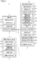
FIG. 2 is a block diagram illustrating a wireless communication system according to an embodiment; -
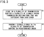
FIG. 3 is a flowchart illustrating an example of operation of a base wireless device according to an embodiment; -
FIG. 4 is a flowchart illustrating an example of operation of a base wireless device according to an embodiment; and -
FIG. 5 is a time chart illustrating an example of operation of the base wireless device according to an embodiment. - A base wireless device and a wireless communication method according to an embodiment will be described below with reference to
FIGS. 1 to 5 .FIG. 1 is a diagram illustrating a wireless communication system according to the present embodiment.FIG. 2 is a block diagram illustrating the wireless communication system according to the present embodiment. - As shown in
FIG. 1 , awireless communication system 10 according to the present embodiment may include acomputer 12, a basewireless device 14, and a remotewireless device 16. Thewireless communication system 10 may include a plurality of basewireless devices 14. Thesingle computer 12 and the plurality of basewireless devices 14 may be connected via afieldbus 17. Pairing may be performed in advance between the basewireless device 14 and the remotewireless device 16. A synchronous connection may be made between the paired basewireless device 14 and the remotewireless device 16. A plurality of remotewireless devices 16 can be synchronously connected to a single basewireless device 14. The basewireless device 14 may transmit signals to and receive signals from the plurality of remotewireless devices 16. A plurality ofnetworks 43 may be configured by synchronously connecting the plurality of remotewireless devices 16 to each of the basewireless devices 14. - The
computer 12 can monitor and control industrial equipment. As thecomputer 12, for example, a PLC (Programmable Logic Controller) may be used, but thecomputer 12 is not limited thereto. As illustrated inFIG. 2 , thecomputer 12 may include, for example, acomputation unit 18 and astorage unit 19. - The
computation unit 18 may include, for example, a processor such as a CPU (Central Processing Unit). That is, thecomputation unit 18 may include processing circuitry. Thecomputation unit 18 includes acontrol unit 20. Although components other than thecontrol unit 20 may be included in thecomputation unit 18, the components other than thecontrol unit 20 are omitted herein for the sake of simplicity of description. Thecontrol unit 20 governs the overall control of thecomputer 12. Thecontrol unit 20 may monitor and control industrial equipment. Thecontrol unit 20 may be realized by programs, which are stored in thestorage unit 19, being executed by thecomputation unit 18. At least a part of thecontrol unit 20 may be realized by an integrated circuit such as an ASIC (Application Specific Integrated Circuit) or an FPGA (Field-Programmable Gate Array). At least a part of thecontrol unit 20 may be an electronic circuit including a discrete device. - The
storage unit 19 may include a volatile memory (not illustrated) and a nonvolatile memory (not illustrated). Examples of the volatile memory may include, for example, a RAM (Random Access Memory) or the like. Examples of the nonvolatile memory may include, for example, a ROM (Read Only Memory), a flash memory, or the like. Data and the like may be stored, for example, in the volatile memory. Programs, tables, maps, and the like may be stored, for example, in the nonvolatile memory. At least a part of thestorage unit 19 may be included in the above-described processor, integrated circuit, or the like. Thestorage unit 19 may further include an HDD (Hard Disk Drive), SSD (Solid State Drive), and the like. - The
computer 12 is provided with an input/output interface 21 for realizing fieldbus connection. Thecomputer 12 may communicate with the basewireless device 14 via thefieldbus 17. - The base
wireless device 14 includes, for example, acomputation unit 22 and astorage unit 23. - The
computation unit 22 may include, for example, a processor such as a CPU. That is, thecomputation unit 22 may include a processing circuit. Thecomputation unit 22 may include acontrol unit 24, anacquisition unit 25, a transmission/reception processing unit 26, and astorage control unit 28. Thecomputation unit 22 may be equipped with other components apart from these components noted above. However, the components other than these components are omitted herein for the sake of simplicity. Thecontrol unit 24, theacquisition unit 25, the transmission/reception processing unit 26, and thestorage control unit 28 may be realized by programs, which are stored in thestorage unit 23, being executed by thecomputation unit 22. Thecontrol unit 24 governs the overall control of the basewireless device 14. At least a part of thecontrol unit 24, theacquisition unit 25, the transmission/reception processing unit 26, and thestorage control unit 28 may be realized by an integrated circuit such as an ASIC or an FPGA. At least a part of thecontrol unit 24, theacquisition unit 25, the transmission/reception processing unit 26, and thestorage control unit 28 may be an electronic circuit including a discrete device. - The
storage unit 23 may include a volatile memory (not illustrated) and a nonvolatile memory (not illustrated). Examples of the volatile memory may include, for example, a RAM or the like. Examples of the non-volatile memory may include, for example, a ROM, a flash memory, or the like. Data and the like may be stored, for example, in the volatile memory. Programs, tables, maps, and the like may be stored, for example, in the nonvolatile memory. At least a part of thestorage unit 23 may be included in the above-described processor, integrated circuit, or the like. - The
base wireless device 14 is provided with an input/output interface 29 for realizing fieldbus connection. Thebase wireless device 14 may be connected to thecomputer 12 via thefieldbus 17 as described above. - The
base wireless device 14 may be provided with acommunication unit 30 for carrying out wireless communication. Thebase wireless device 14 may carry out wireless communication with theremote wireless device 16 using thecommunication unit 30. - The
remote wireless device 16 may be provided in each of the plurality of devices 44 (seeFIG. 1 ) included in the industrial equipment. As an example of thedevice 44, there may be cited a sensor, a valve, and the like, although thedevice 44 is not limited thereto. Theremote wireless device 16 is provided with, for example, acomputation unit 32 and astorage unit 34. - The
computation unit 32 may include, for example, a processor such as a CPU. That is, thecomputation unit 32 may include a processing circuit. Thecomputation unit 32 may include acontrol unit 35 and a transmission/reception processing unit 37. Thecomputation unit 32 may be equipped with other components apart from these components noted above. However, the components other than these components are omitted herein for the sake of simplicity. Thecontrol unit 35 and the transmission/reception processing unit 37 may be realized by programs, which are stored in thestorage unit 34, being executed by thecomputation unit 32. Thecontrol unit 35 governs the overall control of theremote wireless device 16. At least a part of thecontrol unit 35 and the transmission/reception processing unit 37 may be realized by an integrated circuit such as an ASIC or an FPGA. At least a part of thecontrol unit 35 and the transmission/reception processing unit 37 may be an electronic circuit including a discrete device. - The
storage unit 34 may include a volatile memory (not illustrated) and a nonvolatile memory (not illustrated). Examples of the volatile memory may include, for example, a RAM or the like. Examples of the non-volatile memory may include, for example, a ROM, a flash memory, or the like. Data and the like may be stored, for example, in the volatile memory. Programs, tables, maps, and the like may be stored, for example, in the nonvolatile memory. At least a part of thestorage unit 34 may be included in the above-described processor, integrated circuit, or the like. - The
remote wireless device 16 is provided with acommunication unit 42 for carrying out wireless communication. Theremote wireless device 16 may carry out wireless communication with thebase wireless device 14 using thecommunication unit 42. - As described above, the
base wireless device 14 may include the transmission/reception processing unit 26. The transmission/reception processing unit 26 may include atransmission processing unit 26A and areception processing unit 26B. Thetransmission processing unit 26A performs a signal transmission process. Thereception processing unit 26B performs a signal reception process. As described above, theremote wireless device 16 may include the transmission/reception processing unit 37. The transmission/reception processing unit 26 and the transmission/reception processing unit 37 govern transmission/reception processes of signals between theremote wireless device 16 and thebase wireless device 14. Communication by a frequency hopping method may be carried out between thebase wireless device 14 and theremote wireless device 16 that are synchronously connected. That is, between the synchronously connectedbase wireless device 14 andremote wireless device 16, signal transmission and reception may be carried out by switching hopping frequencies at predetermined hopping periods Tfh(n) (seeFIG. 5 ). - As described above, the
base wireless device 14 may be provided with theacquisition unit 25. Theacquisition unit 25 may sequentially acquire signals (data packets) supplied from thecomputer 12. The signal supplied from thecomputer 12 may include information indicating theremote wireless device 16 that is a transmission destination of the signal. - As described above, the
base wireless device 14 may include thestorage unit 23. Thestorage unit 23 may include astandby buffer 45. Theacquisition unit 25 sequentially stores a plurality of signals supplied from thecomputer 12 in thestandby buffer 45. Thestandby buffer 45 may store signals acquired by theacquisition unit 25 in chronological order. - The
storage unit 23 may further include a plurality oftransmission buffers remote wireless device 16. The reference numeral 46 will be used when describing the buffers in general, whereas thereference numerals remote wireless devices 16. A plurality of signals having transmission destinations that are different from each other may be stored in the plurality of transmission buffers 46. That is, when a signal is stored in thetransmission buffer 46B, a signal to be transmitted to a transmission destination different from the transmission destination of the signal stored in thetransmission buffer 46B is stored in thetransmission buffer 46A. When a signal is stored in thetransmission buffer 46A, a signal to be transmitted to a transmission destination different from the transmission destination of the signal stored in thetransmission buffer 46A is stored in thetransmission buffer 46B. - The
transmission processing unit 26A transmits the signals stored in the plurality of transmission buffers 46 in a predetermined order, regardless of whether or not each transmission has been made successfully. Thetransmission processing unit 26A transmits the signals stored in the plurality of transmission buffers 46 in a predetermined order, so as to transmit the signals to each of the plurality ofremote wireless devices 16. - When the
remote wireless device 16 receives the signal from thebase wireless device 14, theremote wireless device 16 transmits to the base wireless device 14 a reception completion notification indicating that the signal has been received. Transmission of a signal from thebase wireless device 14 to theremote wireless device 16 and transmission of a reception completion notification from theremote wireless device 16 to thebase wireless device 14 are carried out within one hopping period. When thereception processing unit 26B receives the reception completion notification within the hopping period in which the signal is transmitted from thebase wireless device 14 to theremote wireless device 16, thecontrol unit 24 determines that the transmission of the signal to theremote wireless device 16 has been made successfully. When thereception processing unit 26B does not receive the reception completion notification within the hopping period in which the signal is transmitted from thebase wireless device 14 to theremote wireless device 16, thecontrol unit 24 determines that the transmission of the signal to theremote wireless device 16 has failed. - As described above, the
base wireless device 14 may include thestorage control unit 28. Thestorage control unit 28 stores a signal that is transmitted to aremote wireless device 16 in the transmission buffer 46. Thestorage control part 28 stores a plurality of signals having transmission destinations that are different from each other in the plurality of transmission buffers 46. When the transmission of the signal stored in the transmission buffer 46 has been made successfully, thestorage control unit 28 performs the following process. That is, in this case, thestorage control unit 28 overwrites the transmission buffer 46 from which transmission has been made successfully, with a signal to be transmitted to a transmission destination different from a transmission destination of a signal stored in a transmission buffer 46 other than the transmission buffer 46 from which transmission has been made successfully, among the plurality of transmission buffers 46. For example, when the transmission of the signal stored in thetransmission buffer 46A has been made successfully, thestorage control unit 28 performs the following control. That is, in this case, thestorage control unit 28 overwrites thetransmission buffer 46A, with a signal to be transmitted to a transmission destination that is different from a transmission destination of the signal stored in thetransmission buffer 46B other than thetransmission buffer 46A, among the plurality of transmission buffers 46. When the transmission of the signal stored in thetransmission buffer 46B has been made successfully, thestorage control unit 28 performs the following control. That is, in this case, thestorage control unit 28 overwrites thetransmission buffer 46B, with a signal to be transmitted to a transmission destination that is different from a transmission destination of the signal stored in thetransmission buffer 46A other than thetransmission buffer 46B, among the plurality of transmission buffers 46. - The
storage control unit 28 stores, in the transmission buffers 46, signals selected from the signals stored in thestandby buffer 45 in accordance with priority. For example, the earlier the time at which the signal was acquired, the higher the priority may be. That is, the priority of a signal acquired earlier by the acquisition unit 25 (acquisition time is old) may be higher than the priority of a signal acquired later by the acquisition unit 25 (acquisition time is new). - The operation of the
base wireless device 14 according to the present embodiment will be described below with reference toFIG. 3. FIG. 3 is a flowchart illustrating an example of operation of the base wireless device according to the present embodiment. The basic operation of transmitting a signal is illustrated inFIG. 3 . - In step S1, the
storage control unit 28 provided in thebase wireless device 14 stores in the plurality of transmission buffers 46 a plurality of signals having transmission destinations that are different from each other. - In step S2, the
transmission processing unit 26A provided in thebase wireless device 14 transmits the signals stored in the plurality of transmission buffers 46 in a predetermined order. The process shown inFIG. 3 may be performed repeatedly. - The operation of the
base wireless device 14 according to the present embodiment will be described below with reference toFIG. 4. FIG. 4 is a flowchart illustrating an example of operation of the base wireless device according to the present embodiment.FIG. 4 shows an example of the operation corresponding to the success or failure of the transmission of the signals stored in the transmission buffers 46. - In step S11, the
control unit 24 determines whether or not the transmission of the signal stored in thetransmission buffer 46A has been made successfully. If the transmission of the signal stored in thetransmission buffer 46A has been made successfully (YES in step S11), the process proceeds to step S12. If the transmission of the signal stored in thetransmission buffer 46A has failed (NO in step S11), the process proceeds to step S13. - In step S12, the
storage control unit 28 overwrites thetransmission buffer 46A with a new signal. That is, thestorage control unit 28 overwrites thetransmission buffer 46A with a signal to be transmitted to a transmission destination that is different from the transmission destination of the signal stored in thetransmission buffer 46B. When step S12 is completed, the process proceeds to step S13. - In step S13, the
control unit 24 determines whether or not the transmission of the signal stored in thetransmission buffer 46B has been made successfully. If the transmission of the signal stored in thetransmission buffer 46B has been made successfully (YES in step S13), the process proceeds to step S14. When the transmission of the signal stored in thetransmission buffer 46B has failed (NO in step S13), the process illustrated inFIG. 4 is completed. - In step S14, the
storage control unit 28 overwrites thetransmission buffer 46B with a new signal. That is, thestorage control unit 28 overwrites thetransmission buffer 46B with a signal to be transmitted to a transmission destination that is different from the transmission destination of the signal stored in thetransmission buffer 46A. When step S14 is completed, the process shown inFIG. 4 is completed. The process shown inFIG. 4 may be performed repeatedly. - The operation of the
base wireless device 14 according to the present embodiment will be described below with reference toFIG. 5. FIG. 5 is a time chart illustrating an example of operation of the base wireless device according to the present embodiment. -
FIG. 5 shows an example in which signals (data packets) DPA to DPC are stored in thestandby buffer 45. The signal DPA is a signal to be transmitted to aremote wireless device 16A among the plurality ofremote wireless devices 16. The signal DPB is a signal to be transmitted to aremote wireless device 16B among the plurality ofremote wireless devices 16. The signal DPC is a signal to be transmitted to aremote wireless device 16C among the plurality ofremote wireless devices 16. The symbol DP will be used when describing the signals in general, and the symbols DPA to DPC will be used when describing the individual signals. - The transmission buffer 46 stores a signal selected from the signals stored in the
standby buffer 45 in accordance with priority. The time at which the signal DPA was acquired by theacquisition unit 25 is earlier than the time at which the signal DPB was acquired by theacquisition unit 25. The time at which the signal DPB was acquired by theacquisition unit 25 is earlier than the time at which the signal DPC was acquired by theacquisition unit 25. Therefore, the priority of the signal DPA is higher than that of the signal DPB. Further, the priority of the signal DPB is higher than the priority of the signal DPC. Therefore, thestorage control unit 28 stores the signal DPA in thetransmission buffer 46A. Thestorage control unit 28 also stores the signal DPB in thetransmission buffer 46B. Since the number of transmission buffers 46 is two, the number of signals that can be simultaneously stored in a plurality of transmission buffers 46 is two. Therefore, the signal DPC is not stored in any of the transmission buffers 46 at this stage. - The signals DP stored in the plurality of transmission buffers 46 are transmitted in a predetermined order. In a hopping period Tfh(1), the signal DPA stored in the
transmission buffer 46A is transmitted. Specifically, the signal DPA is transmitted from thebase wireless device 14 to theremote wireless device 16A.FIG. 5 shows an example in which the transmission of the signal DPA fails in the hopping period Tfh(1). - In a hopping period Tfh(2) subsequent to the hopping period Tfh(1), the signal DPB stored in the
transmission buffer 46B is transmitted. Specifically, the signal DPB is transmitted from thebase wireless device 14 to theremote wireless device 16B.FIG. 5 shows an example in which the transmission of the signal DPB fails in the hopping period Tfh(2). - In a hopping period Tfh(3) subsequent to the hopping period Tfh(2), the signal DPA stored in the
transmission buffer 46A is transmitted. Specifically, the signal DPA is transmitted from thebase wireless device 14 to theremote wireless device 16A.FIG. 5 shows an example in which the transmission of the signal DPA has been made successfully in the hopping period Tfh(3). When the transmission of the signal DPA stored in thetransmission buffer 46A has been made successfully, thetransmission buffer 46A is overwritten with the signal DPC. - In a hopping period Tfh(4) subsequent to the hopping period Tfh(3), the signal DPB stored in the
transmission buffer 46B is transmitted. Specifically, the signal DPB is transmitted from thebase wireless device 14 to theremote wireless device 16B.FIG. 5 shows an example in which the transmission of the signal DPB fails in the hopping period Tfh(4). - In a hopping period Tfh(5) subsequent to the hopping period Tfh(4), the signal DPC stored in the
transmission buffer 46A is transmitted. Specifically, the signal DPC is transmitted from thebase wireless device 14 to theremote wireless device 16C.FIG. 5 shows an example in which the transmission of the signal DPC has been made successfully in the hopping period Tfh(5). - In a hopping period Tfh(6) subsequent to the hopping period Tfh(5), the signal DPB stored in the
transmission buffer 46B is transmitted. Specifically, the signal DPB is transmitted from thebase wireless device 14 to theremote wireless device 16B.FIG. 5 shows an example in which the transmission of the signal DPB has been made successfully in the hopping period Tfh(6). In this way, the transmission of the signals DP may be carried out sequentially. - If the number of transmission buffers 46 is only one, the signal DPC cannot be transmitted until after the transmission of the signal DPB has been made successfully or until after the number of retries of the transmission of the signal DPB reaches a predetermined number. In contrast, since the plurality of transmission buffers 46 are provided in the present embodiment, even if transmission of the signal DPB has failed, the signal DPC may be transmitted. Therefore, as illustrated in
FIG. 5 , the signal DPC may be successfully transmitted before the signal DPB is successfully transmitted. As described above, according to the present embodiment, rapid wireless communication can be realized. - The present invention is not limited to the above-described embodiments, and various configurations can be adopted therein without departing from the essence and gist of the present invention.
- For example, in the above-described embodiment, although an exemplary case has been described in which the number of transmission buffers 46 is two, the present invention is not necessarily limited to this feature. The number of transmission buffers 46 may be three or more.
- The above-described embodiments can be summarized in the following manner.
- The base wireless device (14) carries out transmission and reception of signals to and from the plurality of remote wireless devices (16), and includes the plurality of transmission buffers (46A, 46B) configured to store a plurality of signals to be transmitted to the plurality of remote wireless devices, the plurality of signals having transmission destinations that are different from each other, the transmission processing unit (26A) configured to transmit the signals to the plurality of remote wireless devices respectively, by transmitting the signals stored in the plurality of transmission buffers in a predetermined order, regardless of whether or not each transmission has been made successfully, and the storage control unit (28), wherein when the transmission of the signal (DPA) stored in one of the transmission buffers (46A) has been made successfully, the storage control unit is configured to overwrite the one transmission buffer (46A) from which the transmission has been made successfully, with other signal (DPC) to be transmitted to the transmission destination (16C) that is different from the transmission destination (16B) of the signal (DPB) stored in the transmission buffer (46B) other than the one transmission buffer (46A) from which the transmission has been made successfully, among the plurality of transmission buffers. If the number of transmission buffers is only one, another signal cannot be transmitted until after the transmission of one signal has been made successfully or until after the number of retries of the transmission of the signal DPB has reached a predetermined number. On the other hand, in the configuration of the present invention, since a plurality of transmission buffers are provided, even when transmission of one signal has failed, transmission of another signal can be carried out. Therefore, before one signal is successfully transmitted, another signal can be transmitted successfully. According to such a configuration, rapid wireless communication can be realized.
- The base wireless device further includes the standby buffer (45) configured to store a plurality of signals supplied from the computer (12) connected by the fieldbus (17), wherein the storage control unit stores, in the transmission buffers, signals selected from the signals stored in the standby buffer in accordance with priority. According to such a configuration, signal transmission can be accurately carried out.
- The wireless communication method in which the base wireless device and the plurality of remote wireless devices carry out transmission and reception of signals to and from each other, is provided. The method includes storing (S1), in the plurality of transmission buffers, a plurality of signals to be transmitted to the plurality of remote wireless devices, the plurality of signals having transmission destinations that are different from each other, transmitting (S2) the signals to the plurality of remote wireless devices respectively, by transmitting the signals stored in the plurality of transmission buffers in a predetermined order, regardless of whether or not each transmission has been made successfully, and overwriting (S11 to S14), when a transmission of a signal stored in one of the transmission buffers has been made successfully, the one transmission buffer from which the transmission has been made successfully, with another signal to be transmitted to a transmission destination that is different from a transmission destination of a signal stored in a transmission buffer other than the one transmission buffer from which the transmission has been made successfully, among the plurality of transmission buffers.
Claims (3)
- A base wireless device (14) that carries out transmission and reception of signals to and from a plurality of remote wireless devices (16), comprising:a plurality of transmission buffers (46A, 46B) configured to store a plurality of signals to be transmitted to the plurality of remote wireless devices, the plurality of signals having transmission destinations that are different from each other;a transmission processing unit (26A) configured to transmit the signals to the plurality of remote wireless devices respectively, by transmitting the signals stored in the plurality of transmission buffers in a predetermined order, regardless of whether or not each transmission has been made successfully; anda storage control unit (28), wherein when a transmission of a signal (DPA) stored in one of the transmission buffers (46A) has been made successfully, the storage control unit is configured to overwrite the one transmission buffer (46A) from which the transmission has been made successfully, with another signal (DPC) to be transmitted to a transmission destination (16C) that is different from a transmission destination (16B) of a signal (DPB) stored in a transmission buffer (46B) other than the one transmission buffer (46A) from which the transmission has been made successfully, among the plurality of transmission buffers.
- The base wireless device according to claim 1, further comprising a standby buffer (45) configured to store a plurality of signals supplied from a computer (12) connected by a fieldbus (17),
wherein the storage control unit stores, in the transmission buffers, signals selected from the signals stored in the standby buffer in accordance with priority. - A wireless communication method in which a base wireless device and a plurality of remote wireless devices carry out transmission and reception of signals to and from each other, the method comprising:storing (S1), in a plurality of transmission buffers, a plurality of signals to be transmitted to the plurality of remote wireless devices, the plurality of signals having transmission destinations that are different from each other;transmitting (S2) the signals to the plurality of remote wireless devices respectively, by transmitting the signals stored in the plurality of transmission buffers in a predetermined order, regardless of whether or not each transmission has been made successfully; andoverwriting (S11 to S14), when a transmission of a signal stored in one of the transmission buffers has been made successfully, the one transmission buffer from which the transmission has been made successfully, with another signal to be transmitted to a transmission destination that is different from a transmission destination of a signal stored in a transmission buffer other than the one transmission buffer from which the transmission has been made successfully, among the plurality of transmission buffers.
Applications Claiming Priority (1)
| Application Number | Priority Date | Filing Date | Title |
|---|---|---|---|
| JP2021086143A JP7760839B2 (en) | 2021-05-21 | 2021-05-21 | Base radio device and wireless communication method |
Publications (2)
| Publication Number | Publication Date |
|---|---|
| EP4092994A1 true EP4092994A1 (en) | 2022-11-23 |
| EP4092994B1 EP4092994B1 (en) | 2025-08-13 |
Family
ID=82100664
Family Applications (1)
| Application Number | Title | Priority Date | Filing Date |
|---|---|---|---|
| EP22173162.3A Active EP4092994B1 (en) | 2021-05-21 | 2022-05-13 | Base wireless device and wireless communication method |
Country Status (7)
| Country | Link |
|---|---|
| US (1) | US11916808B2 (en) |
| EP (1) | EP4092994B1 (en) |
| JP (1) | JP7760839B2 (en) |
| KR (1) | KR20220157904A (en) |
| CN (1) | CN115379596A (en) |
| ES (1) | ES3048285T3 (en) |
| IL (1) | IL293067B2 (en) |
Citations (5)
| Publication number | Priority date | Publication date | Assignee | Title |
|---|---|---|---|---|
| EP1003303A2 (en) * | 1998-11-20 | 2000-05-24 | Matsushita Electric Industrial Co., Ltd. | Device and method for time-division multiple access radio communication with data reception acknowledgement |
| US20090238110A1 (en) * | 2006-04-03 | 2009-09-24 | Kyocera Corporation | Base Station Apparatus and Method for Controlling Base Station Apparatus |
| US20130287008A1 (en) * | 2010-12-20 | 2013-10-31 | Nokia Siemens Networks Oy | Channelization Code Sharing Between Multiple Users |
| JP5497730B2 (en) | 2009-02-23 | 2014-05-21 | 三菱電機株式会社 | Wireless communication system, wireless communication apparatus, and wireless communication method |
| EP2854321A1 (en) * | 2000-04-14 | 2015-04-01 | Qualcomm Incorporated | A method and an apparatus for a quick retransmission of signals in a communication system |
Family Cites Families (9)
| Publication number | Priority date | Publication date | Assignee | Title |
|---|---|---|---|---|
| JP2856086B2 (en) * | 1994-12-26 | 1999-02-10 | 日本電気株式会社 | Satellite channel access method |
| JP3003580B2 (en) * | 1996-07-24 | 2000-01-31 | 日本電気株式会社 | Data transmitting / receiving device and data communication system using the same |
| JP2003229896A (en) * | 2002-02-01 | 2003-08-15 | Fujitsu Ltd | Packet transmission scheduling apparatus and packet transmission scheduling method |
| US6741554B2 (en) * | 2002-08-16 | 2004-05-25 | Motorola Inc. | Method and apparatus for reliably communicating information packets in a wireless communication network |
| JP4105221B2 (en) * | 2006-09-20 | 2008-06-25 | 松下電器産業株式会社 | Relay transmission device and relay transmission method |
| JP5168689B2 (en) * | 2008-03-11 | 2013-03-21 | 株式会社国際電気通信基礎技術研究所 | Wireless device and wireless network provided with the same |
| JP6303333B2 (en) * | 2013-08-28 | 2018-04-04 | 富士通株式会社 | Wireless communication apparatus and control method |
| JP6508538B2 (en) | 2016-04-04 | 2019-05-08 | Smc株式会社 | Industrial wireless communication system |
| US10009874B2 (en) * | 2016-04-04 | 2018-06-26 | Smc Corporation | Industrial wireless communications system |
-
2021
- 2021-05-21 JP JP2021086143A patent/JP7760839B2/en active Active
-
2022
- 2022-05-02 US US17/661,655 patent/US11916808B2/en active Active
- 2022-05-13 EP EP22173162.3A patent/EP4092994B1/en active Active
- 2022-05-13 ES ES22173162T patent/ES3048285T3/en active Active
- 2022-05-17 IL IL293067A patent/IL293067B2/en unknown
- 2022-05-19 KR KR1020220061543A patent/KR20220157904A/en active Pending
- 2022-05-20 CN CN202210563277.XA patent/CN115379596A/en active Pending
Patent Citations (5)
| Publication number | Priority date | Publication date | Assignee | Title |
|---|---|---|---|---|
| EP1003303A2 (en) * | 1998-11-20 | 2000-05-24 | Matsushita Electric Industrial Co., Ltd. | Device and method for time-division multiple access radio communication with data reception acknowledgement |
| EP2854321A1 (en) * | 2000-04-14 | 2015-04-01 | Qualcomm Incorporated | A method and an apparatus for a quick retransmission of signals in a communication system |
| US20090238110A1 (en) * | 2006-04-03 | 2009-09-24 | Kyocera Corporation | Base Station Apparatus and Method for Controlling Base Station Apparatus |
| JP5497730B2 (en) | 2009-02-23 | 2014-05-21 | 三菱電機株式会社 | Wireless communication system, wireless communication apparatus, and wireless communication method |
| US20130287008A1 (en) * | 2010-12-20 | 2013-10-31 | Nokia Siemens Networks Oy | Channelization Code Sharing Between Multiple Users |
Also Published As
| Publication number | Publication date |
|---|---|
| US20220377023A1 (en) | 2022-11-24 |
| KR20220157904A (en) | 2022-11-29 |
| CN115379596A (en) | 2022-11-22 |
| JP7760839B2 (en) | 2025-10-28 |
| IL293067B1 (en) | 2025-10-01 |
| IL293067B2 (en) | 2026-02-01 |
| EP4092994B1 (en) | 2025-08-13 |
| JP2022178977A (en) | 2022-12-02 |
| IL293067A (en) | 2022-12-01 |
| US11916808B2 (en) | 2024-02-27 |
| ES3048285T3 (en) | 2025-12-09 |
Similar Documents
| Publication | Publication Date | Title |
|---|---|---|
| RU2568774C2 (en) | Method of controlling operation of bus system, primarily of bus can | |
| KR102789249B1 (en) | Gateway appratus and controlling method thereof | |
| US5553095A (en) | Method and apparatus for exchanging different classes of data during different time intervals | |
| KR102707737B1 (en) | Controller diagnostic device and method thereof | |
| CN111542123B (en) | Time slot scheduling of packets in industrial wireless networks | |
| US20170262340A1 (en) | Relay device, control method of relay device, control program and recording medium | |
| KR100614638B1 (en) | Hybrid Serial Peripheral Interface Interface Suitable for High-Speed Wireless Communication and Its Method | |
| EP3914032B1 (en) | Data communication methods. | |
| US11916808B2 (en) | Base wireless device and wireless communication method | |
| WO2016204986A1 (en) | Rtu serial communication mechanism | |
| EP3082376B1 (en) | Network device discovery method and network device discovery system | |
| CN112600703B (en) | Network equipment remote access fault positioning method and device | |
| KR20190051585A (en) | Sever and network system using the same | |
| US20080256385A1 (en) | Optimization of port link recovery | |
| US9693121B2 (en) | Method for data transmission between measuring apparatuses and a data processing device in a measured data recording system | |
| US20150372837A1 (en) | Communication apparatus, control apparatus, and program | |
| CN113852568A (en) | A data transmission method and safety instrumented system | |
| JP4005044B2 (en) | Communication test equipment | |
| US20240275673A1 (en) | Configuration of an industrial communication system | |
| JP6961561B2 (en) | Wireless control system and control device | |
| KR100606886B1 (en) | Method and apparatus for call maintenance in telecommunication systems | |
| WO2023058116A1 (en) | Communication system and communication method | |
| WO2023058120A1 (en) | Radio communication device and communication method | |
| CN117376367A (en) | Synchronous processing method and device | |
| WO2023058121A1 (en) | Communication system, communication control circuit, and communication method |
Legal Events
| Date | Code | Title | Description |
|---|---|---|---|
| PUAI | Public reference made under article 153(3) epc to a published international application that has entered the european phase |
Free format text: ORIGINAL CODE: 0009012 |
|
| STAA | Information on the status of an ep patent application or granted ep patent |
Free format text: STATUS: THE APPLICATION HAS BEEN PUBLISHED |
|
| AK | Designated contracting states |
Kind code of ref document: A1 Designated state(s): AL AT BE BG CH CY CZ DE DK EE ES FI FR GB GR HR HU IE IS IT LI LT LU LV MC MK MT NL NO PL PT RO RS SE SI SK SM TR |
|
| STAA | Information on the status of an ep patent application or granted ep patent |
Free format text: STATUS: REQUEST FOR EXAMINATION WAS MADE |
|
| 17P | Request for examination filed |
Effective date: 20230519 |
|
| RBV | Designated contracting states (corrected) |
Designated state(s): AL AT BE BG CH CY CZ DE DK EE ES FI FR GB GR HR HU IE IS IT LI LT LU LV MC MK MT NL NO PL PT RO RS SE SI SK SM TR |
|
| GRAP | Despatch of communication of intention to grant a patent |
Free format text: ORIGINAL CODE: EPIDOSNIGR1 |
|
| STAA | Information on the status of an ep patent application or granted ep patent |
Free format text: STATUS: GRANT OF PATENT IS INTENDED |
|
| INTG | Intention to grant announced |
Effective date: 20250409 |
|
| RAP3 | Party data changed (applicant data changed or rights of an application transferred) |
Owner name: SMC CORPORATION |
|
| GRAS | Grant fee paid |
Free format text: ORIGINAL CODE: EPIDOSNIGR3 |
|
| GRAA | (expected) grant |
Free format text: ORIGINAL CODE: 0009210 |
|
| STAA | Information on the status of an ep patent application or granted ep patent |
Free format text: STATUS: THE PATENT HAS BEEN GRANTED |
|
| AK | Designated contracting states |
Kind code of ref document: B1 Designated state(s): AL AT BE BG CH CY CZ DE DK EE ES FI FR GB GR HR HU IE IS IT LI LT LU LV MC MK MT NL NO PL PT RO RS SE SI SK SM TR |
|
| REG | Reference to a national code |
Ref country code: GB Ref legal event code: FG4D |
|
| REG | Reference to a national code |
Ref country code: CH Ref legal event code: EP |
|
| REG | Reference to a national code |
Ref country code: DE Ref legal event code: R096 Ref document number: 602022019253 Country of ref document: DE |
|
| REG | Reference to a national code |
Ref country code: IE Ref legal event code: FG4D |
|
| REG | Reference to a national code |
Ref country code: SE Ref legal event code: TRGR |
|
| REG | Reference to a national code |
Ref country code: ES Ref legal event code: FG2A Ref document number: 3048285 Country of ref document: ES Kind code of ref document: T3 Effective date: 20251209 |
|
| REG | Reference to a national code |
Ref country code: NL Ref legal event code: MP Effective date: 20250813 |
|
| PG25 | Lapsed in a contracting state [announced via postgrant information from national office to epo] |
Ref country code: IS Free format text: LAPSE BECAUSE OF FAILURE TO SUBMIT A TRANSLATION OF THE DESCRIPTION OR TO PAY THE FEE WITHIN THE PRESCRIBED TIME-LIMIT Effective date: 20251213 |
|
| PG25 | Lapsed in a contracting state [announced via postgrant information from national office to epo] |
Ref country code: NO Free format text: LAPSE BECAUSE OF FAILURE TO SUBMIT A TRANSLATION OF THE DESCRIPTION OR TO PAY THE FEE WITHIN THE PRESCRIBED TIME-LIMIT Effective date: 20251113 |
|
| REG | Reference to a national code |
Ref country code: LT Ref legal event code: MG9D |
|
| PG25 | Lapsed in a contracting state [announced via postgrant information from national office to epo] |
Ref country code: PT Free format text: LAPSE BECAUSE OF FAILURE TO SUBMIT A TRANSLATION OF THE DESCRIPTION OR TO PAY THE FEE WITHIN THE PRESCRIBED TIME-LIMIT Effective date: 20251215 |
|
| PG25 | Lapsed in a contracting state [announced via postgrant information from national office to epo] |
Ref country code: FI Free format text: LAPSE BECAUSE OF FAILURE TO SUBMIT A TRANSLATION OF THE DESCRIPTION OR TO PAY THE FEE WITHIN THE PRESCRIBED TIME-LIMIT Effective date: 20250813 |
|
| PG25 | Lapsed in a contracting state [announced via postgrant information from national office to epo] |
Ref country code: HR Free format text: LAPSE BECAUSE OF FAILURE TO SUBMIT A TRANSLATION OF THE DESCRIPTION OR TO PAY THE FEE WITHIN THE PRESCRIBED TIME-LIMIT Effective date: 20250813 Ref country code: NL Free format text: LAPSE BECAUSE OF FAILURE TO SUBMIT A TRANSLATION OF THE DESCRIPTION OR TO PAY THE FEE WITHIN THE PRESCRIBED TIME-LIMIT Effective date: 20250813 |
|
| PG25 | Lapsed in a contracting state [announced via postgrant information from national office to epo] |
Ref country code: GR Free format text: LAPSE BECAUSE OF FAILURE TO SUBMIT A TRANSLATION OF THE DESCRIPTION OR TO PAY THE FEE WITHIN THE PRESCRIBED TIME-LIMIT Effective date: 20251114 |
|
| PG25 | Lapsed in a contracting state [announced via postgrant information from national office to epo] |
Ref country code: LV Free format text: LAPSE BECAUSE OF FAILURE TO SUBMIT A TRANSLATION OF THE DESCRIPTION OR TO PAY THE FEE WITHIN THE PRESCRIBED TIME-LIMIT Effective date: 20250813 |
|
| PG25 | Lapsed in a contracting state [announced via postgrant information from national office to epo] |
Ref country code: BG Free format text: LAPSE BECAUSE OF FAILURE TO SUBMIT A TRANSLATION OF THE DESCRIPTION OR TO PAY THE FEE WITHIN THE PRESCRIBED TIME-LIMIT Effective date: 20250813 Ref country code: PL Free format text: LAPSE BECAUSE OF FAILURE TO SUBMIT A TRANSLATION OF THE DESCRIPTION OR TO PAY THE FEE WITHIN THE PRESCRIBED TIME-LIMIT Effective date: 20250813 |
|
| PG25 | Lapsed in a contracting state [announced via postgrant information from national office to epo] |
Ref country code: RS Free format text: LAPSE BECAUSE OF FAILURE TO SUBMIT A TRANSLATION OF THE DESCRIPTION OR TO PAY THE FEE WITHIN THE PRESCRIBED TIME-LIMIT Effective date: 20251113 |
|
| REG | Reference to a national code |
Ref country code: AT Ref legal event code: MK05 Ref document number: 1825969 Country of ref document: AT Kind code of ref document: T Effective date: 20250813 |
|
| PG25 | Lapsed in a contracting state [announced via postgrant information from national office to epo] |
Ref country code: SM Free format text: LAPSE BECAUSE OF FAILURE TO SUBMIT A TRANSLATION OF THE DESCRIPTION OR TO PAY THE FEE WITHIN THE PRESCRIBED TIME-LIMIT Effective date: 20250813 |
|
| PG25 | Lapsed in a contracting state [announced via postgrant information from national office to epo] |
Ref country code: DK Free format text: LAPSE BECAUSE OF FAILURE TO SUBMIT A TRANSLATION OF THE DESCRIPTION OR TO PAY THE FEE WITHIN THE PRESCRIBED TIME-LIMIT Effective date: 20250813 |
|
| PG25 | Lapsed in a contracting state [announced via postgrant information from national office to epo] |
Ref country code: AT Free format text: LAPSE BECAUSE OF FAILURE TO SUBMIT A TRANSLATION OF THE DESCRIPTION OR TO PAY THE FEE WITHIN THE PRESCRIBED TIME-LIMIT Effective date: 20250813 |
|
| PG25 | Lapsed in a contracting state [announced via postgrant information from national office to epo] |
Ref country code: CZ Free format text: LAPSE BECAUSE OF FAILURE TO SUBMIT A TRANSLATION OF THE DESCRIPTION OR TO PAY THE FEE WITHIN THE PRESCRIBED TIME-LIMIT Effective date: 20250813 |
|
| PG25 | Lapsed in a contracting state [announced via postgrant information from national office to epo] |
Ref country code: EE Free format text: LAPSE BECAUSE OF FAILURE TO SUBMIT A TRANSLATION OF THE DESCRIPTION OR TO PAY THE FEE WITHIN THE PRESCRIBED TIME-LIMIT Effective date: 20250813 Ref country code: SK Free format text: LAPSE BECAUSE OF FAILURE TO SUBMIT A TRANSLATION OF THE DESCRIPTION OR TO PAY THE FEE WITHIN THE PRESCRIBED TIME-LIMIT Effective date: 20250813 |