EP4092939A2 - Systems and methods for nyquist error correction - Google Patents
Systems and methods for nyquist error correction Download PDFInfo
- Publication number
- EP4092939A2 EP4092939A2 EP22170597.3A EP22170597A EP4092939A2 EP 4092939 A2 EP4092939 A2 EP 4092939A2 EP 22170597 A EP22170597 A EP 22170597A EP 4092939 A2 EP4092939 A2 EP 4092939A2
- Authority
- EP
- European Patent Office
- Prior art keywords
- error
- nyquist
- decision
- generate
- output
- Prior art date
- Legal status (The legal status is an assumption and is not a legal conclusion. Google has not performed a legal analysis and makes no representation as to the accuracy of the status listed.)
- Granted
Links
Images





Classifications
-
- H—ELECTRICITY
- H03—ELECTRONIC CIRCUITRY
- H03M—CODING; DECODING; CODE CONVERSION IN GENERAL
- H03M13/00—Coding, decoding or code conversion, for error detection or error correction; Coding theory basic assumptions; Coding bounds; Error probability evaluation methods; Channel models; Simulation or testing of codes
- H03M13/37—Decoding methods or techniques, not specific to the particular type of coding provided for in groups H03M13/03 - H03M13/35
- H03M13/45—Soft decoding, i.e. using symbol reliability information
- H03M13/458—Soft decoding, i.e. using symbol reliability information by updating bit probabilities or hard decisions in an iterative fashion for convergence to a final decoding result
-
- H—ELECTRICITY
- H04—ELECTRIC COMMUNICATION TECHNIQUE
- H04L—TRANSMISSION OF DIGITAL INFORMATION, e.g. TELEGRAPHIC COMMUNICATION
- H04L1/00—Arrangements for detecting or preventing errors in the information received
- H04L1/004—Arrangements for detecting or preventing errors in the information received by using forward error control
- H04L1/0045—Arrangements at the receiver end
- H04L1/0054—Maximum-likelihood or sequential decoding, e.g. Viterbi, Fano, ZJ algorithms
-
- H—ELECTRICITY
- H03—ELECTRONIC CIRCUITRY
- H03M—CODING; DECODING; CODE CONVERSION IN GENERAL
- H03M13/00—Coding, decoding or code conversion, for error detection or error correction; Coding theory basic assumptions; Coding bounds; Error probability evaluation methods; Channel models; Simulation or testing of codes
- H03M13/29—Coding, decoding or code conversion, for error detection or error correction; Coding theory basic assumptions; Coding bounds; Error probability evaluation methods; Channel models; Simulation or testing of codes combining two or more codes or code structures, e.g. product codes, generalised product codes, concatenated codes, inner and outer codes
- H03M13/2906—Coding, decoding or code conversion, for error detection or error correction; Coding theory basic assumptions; Coding bounds; Error probability evaluation methods; Channel models; Simulation or testing of codes combining two or more codes or code structures, e.g. product codes, generalised product codes, concatenated codes, inner and outer codes using block codes
-
- H—ELECTRICITY
- H03—ELECTRONIC CIRCUITRY
- H03M—CODING; DECODING; CODE CONVERSION IN GENERAL
- H03M13/00—Coding, decoding or code conversion, for error detection or error correction; Coding theory basic assumptions; Coding bounds; Error probability evaluation methods; Channel models; Simulation or testing of codes
- H03M13/03—Error detection or forward error correction by redundancy in data representation, i.e. code words containing more digits than the source words
- H03M13/05—Error detection or forward error correction by redundancy in data representation, i.e. code words containing more digits than the source words using block codes, i.e. a predetermined number of check bits joined to a predetermined number of information bits
- H03M13/11—Error detection or forward error correction by redundancy in data representation, i.e. code words containing more digits than the source words using block codes, i.e. a predetermined number of check bits joined to a predetermined number of information bits using multiple parity bits
- H03M13/1102—Codes on graphs and decoding on graphs, e.g. low-density parity check [LDPC] codes
- H03M13/1105—Decoding
-
- H—ELECTRICITY
- H03—ELECTRONIC CIRCUITRY
- H03M—CODING; DECODING; CODE CONVERSION IN GENERAL
- H03M13/00—Coding, decoding or code conversion, for error detection or error correction; Coding theory basic assumptions; Coding bounds; Error probability evaluation methods; Channel models; Simulation or testing of codes
- H03M13/25—Error detection or forward error correction by signal space coding, i.e. adding redundancy in the signal constellation, e.g. Trellis Coded Modulation [TCM]
- H03M13/256—Error detection or forward error correction by signal space coding, i.e. adding redundancy in the signal constellation, e.g. Trellis Coded Modulation [TCM] with trellis coding, e.g. with convolutional codes and TCM
-
- H—ELECTRICITY
- H03—ELECTRONIC CIRCUITRY
- H03M—CODING; DECODING; CODE CONVERSION IN GENERAL
- H03M13/00—Coding, decoding or code conversion, for error detection or error correction; Coding theory basic assumptions; Coding bounds; Error probability evaluation methods; Channel models; Simulation or testing of codes
- H03M13/33—Synchronisation based on error coding or decoding
-
- H—ELECTRICITY
- H03—ELECTRONIC CIRCUITRY
- H03M—CODING; DECODING; CODE CONVERSION IN GENERAL
- H03M13/00—Coding, decoding or code conversion, for error detection or error correction; Coding theory basic assumptions; Coding bounds; Error probability evaluation methods; Channel models; Simulation or testing of codes
- H03M13/37—Decoding methods or techniques, not specific to the particular type of coding provided for in groups H03M13/03 - H03M13/35
- H03M13/3707—Adaptive decoding and hybrid decoding, e.g. decoding methods or techniques providing more than one decoding algorithm for one code
- H03M13/3715—Adaptation to the number of estimated errors or to the channel state
-
- H—ELECTRICITY
- H03—ELECTRONIC CIRCUITRY
- H03M—CODING; DECODING; CODE CONVERSION IN GENERAL
- H03M13/00—Coding, decoding or code conversion, for error detection or error correction; Coding theory basic assumptions; Coding bounds; Error probability evaluation methods; Channel models; Simulation or testing of codes
- H03M13/63—Joint error correction and other techniques
- H03M13/6331—Error control coding in combination with equalisation
-
- H—ELECTRICITY
- H03—ELECTRONIC CIRCUITRY
- H03M—CODING; DECODING; CODE CONVERSION IN GENERAL
- H03M13/00—Coding, decoding or code conversion, for error detection or error correction; Coding theory basic assumptions; Coding bounds; Error probability evaluation methods; Channel models; Simulation or testing of codes
- H03M13/63—Joint error correction and other techniques
- H03M13/6343—Error control coding in combination with techniques for partial response channels, e.g. recording
-
- H—ELECTRICITY
- H03—ELECTRONIC CIRCUITRY
- H03M—CODING; DECODING; CODE CONVERSION IN GENERAL
- H03M13/00—Coding, decoding or code conversion, for error detection or error correction; Coding theory basic assumptions; Coding bounds; Error probability evaluation methods; Channel models; Simulation or testing of codes
- H03M13/65—Purpose and implementation aspects
- H03M13/6502—Reduction of hardware complexity or efficient processing
-
- H—ELECTRICITY
- H04—ELECTRIC COMMUNICATION TECHNIQUE
- H04L—TRANSMISSION OF DIGITAL INFORMATION, e.g. TELEGRAPHIC COMMUNICATION
- H04L1/00—Arrangements for detecting or preventing errors in the information received
- H04L1/004—Arrangements for detecting or preventing errors in the information received by using forward error control
- H04L1/0041—Arrangements at the transmitter end
-
- H—ELECTRICITY
- H04—ELECTRIC COMMUNICATION TECHNIQUE
- H04L—TRANSMISSION OF DIGITAL INFORMATION, e.g. TELEGRAPHIC COMMUNICATION
- H04L1/00—Arrangements for detecting or preventing errors in the information received
- H04L1/004—Arrangements for detecting or preventing errors in the information received by using forward error control
- H04L1/0045—Arrangements at the receiver end
- H04L1/0052—Realisations of complexity reduction techniques, e.g. pipelining or use of look-up tables
- H04L1/0053—Realisations of complexity reduction techniques, e.g. pipelining or use of look-up tables specially adapted for power saving
-
- H—ELECTRICITY
- H04—ELECTRIC COMMUNICATION TECHNIQUE
- H04L—TRANSMISSION OF DIGITAL INFORMATION, e.g. TELEGRAPHIC COMMUNICATION
- H04L1/00—Arrangements for detecting or preventing errors in the information received
- H04L1/004—Arrangements for detecting or preventing errors in the information received by using forward error control
- H04L1/0056—Systems characterized by the type of code used
- H04L1/0057—Block codes
-
- H—ELECTRICITY
- H04—ELECTRIC COMMUNICATION TECHNIQUE
- H04L—TRANSMISSION OF DIGITAL INFORMATION, e.g. TELEGRAPHIC COMMUNICATION
- H04L1/00—Arrangements for detecting or preventing errors in the information received
- H04L1/004—Arrangements for detecting or preventing errors in the information received by using forward error control
- H04L1/0056—Systems characterized by the type of code used
- H04L1/0061—Error detection codes
-
- H—ELECTRICITY
- H04—ELECTRIC COMMUNICATION TECHNIQUE
- H04L—TRANSMISSION OF DIGITAL INFORMATION, e.g. TELEGRAPHIC COMMUNICATION
- H04L1/00—Arrangements for detecting or preventing errors in the information received
- H04L1/004—Arrangements for detecting or preventing errors in the information received by using forward error control
- H04L1/0056—Systems characterized by the type of code used
- H04L1/0071—Use of interleaving
-
- H—ELECTRICITY
- H04—ELECTRIC COMMUNICATION TECHNIQUE
- H04L—TRANSMISSION OF DIGITAL INFORMATION, e.g. TELEGRAPHIC COMMUNICATION
- H04L25/00—Baseband systems
- H04L25/02—Details ; arrangements for supplying electrical power along data transmission lines
- H04L25/03—Shaping networks in transmitter or receiver, e.g. adaptive shaping networks
- H04L25/03006—Arrangements for removing intersymbol interference
- H04L25/03178—Arrangements involving sequence estimation techniques
-
- H—ELECTRICITY
- H03—ELECTRONIC CIRCUITRY
- H03M—CODING; DECODING; CODE CONVERSION IN GENERAL
- H03M13/00—Coding, decoding or code conversion, for error detection or error correction; Coding theory basic assumptions; Coding bounds; Error probability evaluation methods; Channel models; Simulation or testing of codes
- H03M13/03—Error detection or forward error correction by redundancy in data representation, i.e. code words containing more digits than the source words
- H03M13/05—Error detection or forward error correction by redundancy in data representation, i.e. code words containing more digits than the source words using block codes, i.e. a predetermined number of check bits joined to a predetermined number of information bits
- H03M13/13—Linear codes
- H03M13/15—Cyclic codes, i.e. cyclic shifts of codewords produce other codewords, e.g. codes defined by a generator polynomial, Bose-Chaudhuri-Hocquenghem [BCH] codes
- H03M13/151—Cyclic codes, i.e. cyclic shifts of codewords produce other codewords, e.g. codes defined by a generator polynomial, Bose-Chaudhuri-Hocquenghem [BCH] codes using error location or error correction polynomials
- H03M13/1515—Reed-Solomon codes
-
- H—ELECTRICITY
- H03—ELECTRONIC CIRCUITRY
- H03M—CODING; DECODING; CODE CONVERSION IN GENERAL
- H03M13/00—Coding, decoding or code conversion, for error detection or error correction; Coding theory basic assumptions; Coding bounds; Error probability evaluation methods; Channel models; Simulation or testing of codes
- H03M13/03—Error detection or forward error correction by redundancy in data representation, i.e. code words containing more digits than the source words
- H03M13/05—Error detection or forward error correction by redundancy in data representation, i.e. code words containing more digits than the source words using block codes, i.e. a predetermined number of check bits joined to a predetermined number of information bits
- H03M13/13—Linear codes
- H03M13/15—Cyclic codes, i.e. cyclic shifts of codewords produce other codewords, e.g. codes defined by a generator polynomial, Bose-Chaudhuri-Hocquenghem [BCH] codes
- H03M13/151—Cyclic codes, i.e. cyclic shifts of codewords produce other codewords, e.g. codes defined by a generator polynomial, Bose-Chaudhuri-Hocquenghem [BCH] codes using error location or error correction polynomials
- H03M13/152—Bose-Chaudhuri-Hocquenghem [BCH] codes
-
- H—ELECTRICITY
- H03—ELECTRONIC CIRCUITRY
- H03M—CODING; DECODING; CODE CONVERSION IN GENERAL
- H03M13/00—Coding, decoding or code conversion, for error detection or error correction; Coding theory basic assumptions; Coding bounds; Error probability evaluation methods; Channel models; Simulation or testing of codes
- H03M13/03—Error detection or forward error correction by redundancy in data representation, i.e. code words containing more digits than the source words
- H03M13/05—Error detection or forward error correction by redundancy in data representation, i.e. code words containing more digits than the source words using block codes, i.e. a predetermined number of check bits joined to a predetermined number of information bits
- H03M13/13—Linear codes
- H03M13/19—Single error correction without using particular properties of the cyclic codes, e.g. Hamming codes, extended or generalised Hamming codes
Definitions
- the present invention is directed to communication systems and methods.
- the present invention is directed to communication systems and methods.
- the present invention provides a receiver that includes an error correction module.
- a syndrome value calculated based on received signals, may be used to enable the error correction module.
- the error correction module includes an error generator, a Nyquist error estimator, and a decoder.
- the decoder uses error estimation generated by the Nyquist error estimator to correct the decoded data.
- the present invention provides a receiver device that includes an equalizer configured to provide equalized signals based on received signals.
- the device also includes a detector configured to generate a first decision based on the equalized signals.
- the device also includes a demapper configured to generate a first output based at least on the first decision.
- the device further includes an error correction module configured to generate a second output based on at least the first decision and an error indicator.
- the error correction module may include a Nyquist error estimator for generating the error indicator based at least on the equalized signals and the first decision.
- the device also includes a syndrome calculator configured to calculator a syndrome value based on the first output.
- the device also includes a selector configured to select between the first output and the second output based at least on the syndrome value.
- the present invention provides an error correction device that includes an error generator configured to generate an intermediate signal based on least an input signal and a first decision.
- the first decision is based on the input signal.
- the device also includes a Nyquist error estimator that is configured to generate an error indicator using at least the intermediate signal and the first decision.
- the device also includes a decoder that is configured to generate an output based at least on the error indicator and the first decision.
- the Nyquist error estimator operates on an error event trellis with a pair of lists, and it updates the pair of lists recursively.
- the present invention provides a method for processing received data.
- the method includes receiving an input signal.
- the method also includes equalizing the input signal to provide an equalized signal.
- the method also includes generating a first decision based on the equalized signal.
- the method also includes demapping the first decision to generate a first output.
- the method also includes determining a syndrome value associated with the first output.
- the method also includes generating a second output using an error correction process if the syndrome value is non-zero.
- the error correction process includes a Nyquist error estimation process.
- the method also includes selecting between the first output and the second output using the syndrome value.
- the present invention provides a transmitter device that includes an RS symbol interleaver configured to generate RS symbols from RS codewords.
- the device also includes a first PAM-n mapper configured to generate a first set of PAM-n symbols based on the RS symbols.
- the device also includes a bit selector module configured to select a subset of bits from the first set of PAM-n symbols.
- the device also includes a parity generator configured to generate parity bits using the subset of bits.
- the device also includes a second PAM-n mapper configured to get a second set of PAM-n symbols using the parity bits.
- the device also includes a concatenation module configured to concatenate the first set of PAM-n symbols and the second set of PAM-n symbols to generate a concatenated data steam.
- the device also includes a pilot symbol insertion module configured to insert pilot symbols to the concatenated data stream.
- embodiments of the present invention provide many advantages over conventional techniques. Among other things, error detection and correction mechanism according to embodiments of the present invention provide meaningful and effective performance boost. In various implementations, a control logic activates error correction mechanisms only when needed, thereby saving power.
- Embodiments of the present invention can be implemented in conjunction with existing systems and processes.
- error correction techniques can be implemented in conjunction with existing systems.
- error correction techniques may be configured on devices that are manufactured using existing manufacturing processes and techniques, and thus can be conveniently implemented. There are other benefits as well.
- the present invention is directed to communication systems and methods.
- the present invention provides a receiver that includes an error correction module.
- a syndrome value calculated based on received signals, may be used to enable the error correction module.
- the error correction module includes an error generator, a Nyquist error estimator, and a decoder.
- the decoder uses error estimation generated by the Nyquist error estimator to correct the decoded data.
- any element in a claim that does not explicitly state "means for” performing a specified function, or “step for” performing a specific function, is not to be interpreted as a "means” or “step” clause as specified in 35 U.S.C. Section 112, Paragraph 6.
- the use of "step of' or “act of' in the Claims herein is not intended to invoke the provisions of 35 U.S.C. 112, Paragraph 6.
- communications between two entities are FEC encoded.
- pulse-amplitude modulation may be used.
- the incoming traffic received by a receiver may be encoded in a concatenated FEC scheme.
- the traffic may be first encoded by a Reed- Solomon (RS) encoder, and a suitably interleaved set of RS symbols is encoded by a second block FEC encoder.
- RS Reed- Solomon
- other encoding schemes may be used as well.
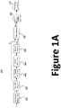
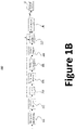
- Figures 1A and 1B illustrate two exemplary FEC encoding mechanisms that are appropriate for systems impaired by Nyquist error events. In both mechanisms, it is assumed that a first RS symbol interleaving block generates a payload u of m RS symbols from distinct RS codewords, followed by a first PAM-N mapper that generates a set of PAM-N symbols d I .
- FIG. 1A is a simplified block diagram illustrating encoder 100 according to embodiments of the present invention. This diagram is merely an example, which should not unduly limit the scope of the claims. One of ordinary skill in the art would recognize many variations, alternatives, and modifications.
- RS symbol interleaving block 101 generates a payload u of m RS symbols from distinct RS codewords, followed by PAM-N mapper 102 that generates a set of PAM-N symbols d I . Based on the d I , block 103 selects a subset of the bits (from the PAM-N bit-labeling) from which to compute FEC parity bits.
- PAM-N mapper 102 implements a binary mapping
- the subset selector 103 may select the least-significant bit of each PAM-N symbol.
- parity generator 104 e.g., systematic linear block encoder
- Parity bits p are mapped by PAM-N mapper 105.
- PAM-N mapper 105 may implement a different mapping scheme from PAM-N mapper 102.
- PAM-N mapper 105 may implement a Gray mapping.
- Concatenation is provided at block 106 that concatenate d I from block 102 and d p from block 105.
- Concatenated data [ d I , d p ] is processed at block 107 before transmission over the channel.
- block 107 comprises a 1/(1 ⁇ D) modulo-N precoder, which may be optional depending on the implementation.
- pilot symbols may be inserted at FEC block codeword boundaries (or, after every n -th codeword, for n -th small positive integer).
- the trellis termination provided by pilot symbols significantly reduces the overlap that would otherwise be required between parallel implementations of the sequence detector.
- block 120 provides pilot symbol insertion.
- pilot symbols uniquely identify the FEC encoding schemes and allows the trellis (as used by the receiver) to start and end in a known state over the span of 1 or more FEC code words.
- FIG. 1B is a simplified block diagram illustrating encoder 110 according to embodiments of the present invention. This diagram is merely an example, which should not unduly limit the scope of the claims. One of ordinary skill in the art would recognize many variations, alternatives, and modifications.
- RS symbol interleaving block 111 generates a payload u of m RS symbols from distinct RS codewords, followed by PAM-N mapper 112 that generates a set of PAM-N symbols d I .
- Block 113 is configured to, among other things, address Nyquist error events.
- block 113 with (1 ⁇ D) modulo-N filter is configured prior to the bit subset selector 114. Based on the output of the bit subset selector 114, parity generator 115 generates parity bits.
- Block 117 (e.g., with 1/(1 ⁇ D) modulo-N precoder) is configured after PAM-N mapper 116, and its state (initialized for the first PAM-N parity symbol) is based on the last symbol in d I .
- the resulting pre-coded PAM-N symbols d p are concatenated with the d I for transmission.
- Block 121 is configured after block 118 and provides pilot symbol insertion. For example, pilot symbols uniquely identify the FEC encoding schemes and allow the trellis (as used by the receiver) to start and end in a known state over the span of 1 or more FEC code words.
- FIG 2 is a simplified block diagram illustrating a receiver 200 according to embodiments of the present invention.
- This diagram is merely an example, which should not unduly limit the scope of the claims.
- receiver 200 includes other components (e.g., optical interface, input circuit, clock recovery circuits, and others) that are not shown in Figure 2 .
- block 201 is configured after input signals are received from an input circuit and performs equalization. It is appreciated that block 201 may be configured using various types of equalizers, including feed-forward equalizer (FFE).
- FFE feed-forward equalizer
- the received signal is equalized to a partial response of the form 1 + ⁇ D, where 0 ⁇ ⁇ ⁇ 1 is the amplitude of the first post-cursor inter-symbol interference (ISI).
- ISI inter-symbol interference
- Detector 202 generates a first set of decisions d ⁇ k .
- detector 202 may be a decision-feedback equalizer (DFE), a maximum-likelihood sequence detector (MLSD), or a hybrid of multiple detector types.
- DFE decision-feedback equalizer
- MLSD maximum-likelihood sequence detector
- error-event MLSD is a hybrid approach- a trellis-based Nyquist-error correcting scheme post-processes the FFE and DFE outputs in order to approximate an MLSD receiver-that was described in U.S. Patent No. 10,637,512 and U.S. Patent No. 10,404,289 , both of which are commonly owned and incorporated by reference in here.
- a Nyquist error event refers to a burst of consecutive decision errors (i.e., d ⁇ k ⁇ d k for a range of consecutive values of k), where the polarity of the decision error alternates (e.g., + - + - + -).
- Demapper 203 inverts the mapping applied in the transmitter, in order to recover a first estimate ⁇ k of the transmitted FEC codeword bits from the d ⁇ k .
- demapper 203 may include an inverse precoder.
- Block 204 calculates the syndrome of ⁇ k . If the syndrome is satisfied (i.e., all-zeros), then the payload bits from the codeword are mapped directly to the output u k (note that this is without any loss in performance whenever the detector provides decisions corresponding to the maximum likelihood sequence).
- block 210 is enabled, which includes a Nyquist-error-based sequence estimation and corresponding Nyquist-error-based soft-decision decoder.
- block 210 may be referred to as an error correction circuit that includes error generator 211, Nyquist error estimator 212, and soft FEC decoder 213.
- error generator 211 generates an intermediate signal y k that is based on signal x k and d ⁇ k as shown.
- Nyquist error estimator 212 configured to generate an error estimation using its input y k and d ⁇ k .
- Decoder 213 is configured to generate an output u k by updating decision d ⁇ k with error estimation calculated by the Nyquist error estimator 212.
- Selector 205 (e.g., implemented with a multiplexor) selects output based on the syndrome calculation performed by block 204.
- receiver 200 as illustrated provides a significant advantage in power consumption, since the frequency at which the Nyquist-error-based estimation and decoding are enabled is one-quarter or less in practice, without performance degradation.
- Detailed description below provides a Nyquist-error-based sequence estimation and an architecture for performing soft-decision decoding with a Nyquist-error-based maximum-likelihood codeword metric.
- soft-decision estimation and decoding systems for partial response channels may include a codeword interleaver, which is configured in order to spread the burst error events across multiple codewords. In turn, if the interleaving depth is sufficient, the soft-decision decoder can assume that the input errors are independent. According to certain embodiments, interleaving over codewords is not used, at least for two reasons. First, the soft-decision estimation and decoding systems only need to be enabled when the first syndrome calculation is not satisfied (e.g., the output of block 204 used as an enable signal). Second, block 213 uses a soft-decision decoding algorithm that explicitly models the correlated Nyquist error events. The first has the advantage that it reduces power consumption in the receiver, and the second has the advantage that superior performance is achievable when the decoding algorithm accurately models the correlation of errors.
- pilot symbols may be inserted at FEC block codeword boundaries (or, after every n -th codeword, for n a small positive integer).
- the trellis termination provided by pilot symbols significantly reduces the overlap that would otherwise be required between parallel implementations of the sequence detector.
- receiver 200 employs a hybrid ee-MLSD scheme that is configured as a special case of a more powerful Nyquist-error post-processing scheme, which can be suitable for both detection (i.e., hard) and estimation (i.e., soft).
- Different variants of the scheme can be used to perform the role of the detector (at the FFE output) and/or the Nyquist error estimator (to enable soft Nyquist-error-event-based FEC decoding).
- metric M ⁇ k y k ⁇ ⁇ k + ⁇ k ⁇ 1 2 , wherein y k ⁇ e k / 2
- each detector decision e.g., to enable soft-decision decoding of an FEC code
- calculations are needed to provide a list of sequences (and their associated metrics) that provide the second-best, third best (and so on) metrics.
- the list of error sequences may be converted into a reliability measure for each UI.
- Nyquist error estimation is determined using a trellis.
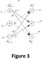
- FIG. 3 is a simplified diagram illustrating trellis 300 for a Nyquist error estimator according to embodiments of the present invention. This diagram is merely an example, which should not unduly limit the scope of the claims. One of ordinary skill in the art would recognize many variations, alternatives, and modifications. Following the definition of a Nyquist error event, the detection and estimation schemes can be interpreted to operate on a trellis 300 with three states. The "0" state is the state from/to which Nyquist error events begin/terminate.
- Nyquist-error-based detection and estimation schemes are described in terms of a pair of lists, L k + and L k ⁇ , that are updated recursively at each time k.
- the list L k + consists of the elements l 1 , k + , l 2 , k + , ... , l L k + , k + .
- Each of the l j , k + is a 3-tuple ( i j,k , s j,k , M j,k ), where i j,k is the time index associated with the start of a Nyquist error event, s j,k is the sign of the associated error at time i j,k , and M j,k is the path metric.
- L k + The elements of L k + are ordered in the following sense: if 1 ⁇ m ⁇ n ⁇ L k ⁇ , then M m,k ⁇ M n,k
- L k ⁇ consists of the elements l 1 , k ⁇ , l 2 , k ⁇ , ... , l L k ⁇ , k ⁇ , with the same properties and definitions of L k + .
- L ⁇ L k + + L k ⁇ is constant.
- dependent variables that cannot be determined unless the state metrics are known; they are referred to as "dependent" variables determined by "dependent” calculations using state metrics.
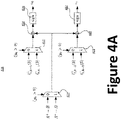
- FIGS 4A-C are simplified diagrams illustrating updating trellis metrics using multiplexors according to embodiments of the present invention. This diagram is merely an example, which should not unduly limit the scope of the claims. One of ordinary skill in the art would recognize many variations, alternatives, and modifications.
- a trellis path e.g., trellis 300
- mux selectors 411, 412, and 413 whose selection is based on the result of operation y k > 0.
- Operators 414 and 415 combine the outputs of these selectors as shown.
- At the outputs of sign operators 416 and 417 are variables a 0 and a 1 respectively.
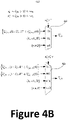
- Variables a 0 and a 1 are used for updating lists l 0 , k ⁇ 1 + and l 1 , k ⁇ 1 + as shown in Figure 4B .
- Variables s 0 + and s 0 ⁇ are both calculated using variables a 0 and a 1 respectively, and they are used as the conditions for mux selectors 421 and 422 in the outputting l 0 , k + and l 1 , k + .
- variables a 0 and a 1 are used for updating lists l 0 , k ⁇ 1 ⁇ and l 1 , k ⁇ 1 ⁇ as shown in Figure 4B .
- Variables s 0 + and s 0 ⁇ are both calculated using variables a 0 and a 1 respectively, and they are used as the conditions for mux selectors 431 and 432 in the outputting l 0 , k ⁇ and l 1 , k ⁇ .
- the ee-buffer is configured as a part of a soft decoder (e.g., decoder 213 in Figure 2 .
- the soft decoder is configured to perform the following steps:
- soft decoders can be implemented in various ways, as described in further detail below.
- the process of updating list lengths is determined using the process below:
- mux selector 503 selects its output based on variables w 0 w 1 , which implements the "if' conditions.
- List update equations may be used to update the pair of lists for the trellis. For example, at every time step k, lists L k + and L k ⁇ are updated. Intuitively, the process starts with a comparison as to whether the error event beginning at time k is more likely than the continuation of a competing error event enumerated at time k - 1.
- the next step is to ensure that the list element that is deleted is the element (from either list) with the largest metric.
- it is determined that an error event beginning at time k is to be added it is inserted into the appropriate position of the relevant list; this ensures that the lists always remain sorted with respect to their metrics.
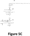
- the list L k + may be updated using the process (e.g., in the form of pseudo code) below, which may be implemented using mux selectors 521 and 522 illustrated in Figure 5B .
- the list L k ⁇ may be updated using the process (e.g., in the form of pseudo code) below, which may be implemented using mux selectors 531 and 532 illustrated in Figure 5C :
- D in the list update equations arises from the fact that when a path merging into the '0' state with negative metric is determined, future error events emerging from the '0 ' state need to be preferred relative to any surviving error events that did not pass through the same '0' state.
- each of the L paths that were unterminated at time k - 1 can merge into the error-free state; the corresponding Nyquist error events terminate at time k .
- a list E k can be stored for each time k that consists of some subset of the paths terminating at time k.
- Each element of E k includes the start index, the sign of the start of the Nyquist error, and the metric of the terminating path; the terminating index of the Nyquist error event is implied. Note that the number of elements in the E k need not be equal to L.
- One of the approaches to minimize complexity is to add to E k the elements from either the paths emanating from the " +1" or the "-1 " error state, but not both. The choice of which set of paths to add can be determined by comparing the metric of the most likely error event from each state.
- the proposed Nyquist-error-based soft-decision FEC decoder (e.g., decoder 213 in Figure 2 ) only requires that the N most likely Nyquist error events over the span of the FEC codeword be determined. This can be accomplished by tracing-through the E k for k in the span of the FEC codeword boundaries, and storing a list of the N error events with the smallest metrics. In practice, this consists of merging sorted lists at each k , discarding all but the N most likely at each k. It is to be noted that calculation of the trellis outputs (and any post-processing) is decoupled from the list update equations, and thus does not contribute to their critical path.
- a maximum sequence likelihood or a maximum symbol likelihood can be performed by post-processing ⁇ .
- maximum symbol likelihood an input decision d ⁇ k is flipped if its index falls within the span of a Nyquist error event for which the metric is negative; if it falls within the span of multiple Nyquist error events with negative metrics, then it should be flipped based on the error event with the smallest metric.
- ⁇ is post-processed to determine the set of non-overlapping Nyquist error events (with negative metrics) whose metrics sum to the smallest metric. The resulting set of error events is used to flip the corresponding values of d ⁇ k .
- a greedy algorithm (closely approximating the optimal post-processor) consists of purging ⁇ from any Nyquist error events that intersect with the most likely Nyquist error event, and then similarly purging with respect to the second most likely remaining path, and so on.
- Nyquist-error-based soft-decision FEC decoder only requires that the N most likely Nyquist error events (over the span of the FEC codeword) be determined (i.e., the list ⁇ described above). More generally, the trellis outputs E k (or the compressed list ⁇ ) can be used to directly calculate an approximation to the maximum a posteriori probability (MAP) of each symbol.
- MAP maximum a posteriori probability
- Equation 6 Equation 6
- x d ⁇ is the sequence of decisions from the detector at the FFE output
- x the sequence of FFE outputs
- e the set of all Nyquist error events. Since P ( d ⁇ +e
- Nyquist error estimation is implemented for a system that uses PAM for communication.
- PAM-4 the approach applies to any PAM-N. It is useful to differentiate two types of non-linearities.
- the g(d k , d k-1 ) represents nonlinearities with memory (e.g., a term of the form ⁇ d k , d k-1 .
- ⁇ k s k ⁇ 1 + ⁇ a k
- s k ⁇ ⁇ 1 the sign of the error
- a(k) denotes the sub-eye index corresponding to d ⁇
- the ⁇ account for the non-uniform spacing of PAM-4 levels.
- approximations may be applied to simplify the calculation of the variable ⁇ .
- a soft-decision FEC decoder processes the detector output decisions d k , the list ⁇ of the N most likely error events, and optionally the error generator output.
- Each element of the list ⁇ provides the starting index, ending index, the polarity of starting error, and the metric of the Nyquist error event.
- a Nyquist-error-based soft-decision decoder Similar in spirit to a classic Chase decoder, a Nyquist-error-based soft-decision decoder generates a set of candidate decoder inputs, and each candidate is decoded by a hard-decision decoder. For each candidate, the reliability of the decoded codeword is calculated by determining the difference between the detector output decisions d ⁇ and the decoded codeword decisions. Specifically, the difference is expressed in terms of one or more Nyquist error events, and an analytical expression may be used to calculate the resulting decoder metric. The output of the Nyquist-error-based soft-decision FEC decoder is the codeword with the smallest metric.
- a set of hard-decision decoder input candidates can be generated by flipping the detector output decisions d ⁇ (and correspondingly performing the receiver demapping on the resulting decisions) corresponding to different combinations of error events.
- N candidate codewords may be generated, each corresponding to a single error event in ⁇ .
- the N(N-1) / 2 candidate codewords may be generated, each corresponding to a unique pair of error events in ⁇ , and so on for three or more error events per codeword. It is also possible to consider flipping individual bits (e.g., either the error at the start or the end of an error event) from any subset of error events.
- the difference between the detector output decisions d ⁇ and the decoded codeword decisions must be expressed in terms of a set of Nyquist error events (i.e., for each event, the indices of the start, k s , and end, k e ).
- the candidate codeword metric is then the sum of the metrics of its constituent Nyquist error events. Note that a Nyquist error event is only valid if the resulting output decisions result in a valid PAM-N sequence, and that any invalid error event results in rejection of the candidate codeword.
- the Chase-style decoder is further restricted to only flip non-overlapping Nyquist error events, i.e., unlike the more general case, it does not consider flipping only the first or only the last position in a Nyquist error event.
- a further significant advantage is that the calculation of the codeword metric (when the syndrome is satisfied) is simply the sum of the metrics of the associated Nyquist error events (i.e., no calculation of error event metrics is required), and the error generator output can be discarded once the Nyquist error-event list has been computed.
- Figures 6A-E are plots illustrating the performance of a Nyquist error estimator at different settings, for a range of ⁇ , using the first encoding scheme with a (68; 60) extended-Hamming code (for parity generation) and with precoding disabled.
- Figures 6A-E show the performance for different settings of L and L D .
Landscapes
- Engineering & Computer Science (AREA)
- Physics & Mathematics (AREA)
- Probability & Statistics with Applications (AREA)
- Theoretical Computer Science (AREA)
- Computer Networks & Wireless Communication (AREA)
- Signal Processing (AREA)
- Power Engineering (AREA)
- Artificial Intelligence (AREA)
- Error Detection And Correction (AREA)
Abstract
Description
- The present invention is directed to communication systems and methods.
- Internet and mobile applications nowadays demand a huge amount of bandwidth for transferring photos, video, music, and other multimedia files. To meet the bandwidth and capacity demands, high-speed data communication systems are deployed. Research and development efforts have been made to improve the bandwidth of communication systems. Various types of error correction mechanisms have been developed over the years.
- Unfortunately, conventional systems and methods have been inadequate. Improved communication techniques are desired.
- The present invention is directed to communication systems and methods. In a specific embodiment, the present invention provides a receiver that includes an error correction module. A syndrome value, calculated based on received signals, may be used to enable the error correction module. The error correction module includes an error generator, a Nyquist error estimator, and a decoder. The decoder uses error estimation generated by the Nyquist error estimator to correct the decoded data. There are other embodiments as well.
- According to an embodiment, the present invention provides a receiver device that includes an equalizer configured to provide equalized signals based on received signals. The device also includes a detector configured to generate a first decision based on the equalized signals. The device also includes a demapper configured to generate a first output based at least on the first decision. The device further includes an error correction module configured to generate a second output based on at least the first decision and an error indicator. The error correction module may include a Nyquist error estimator for generating the error indicator based at least on the equalized signals and the first decision. The device also includes a syndrome calculator configured to calculator a syndrome value based on the first output. The device also includes a selector configured to select between the first output and the second output based at least on the syndrome value.
- According to another embodiment, the present invention provides an error correction device that includes an error generator configured to generate an intermediate signal based on least an input signal and a first decision. The first decision is based on the input signal. The device also includes a Nyquist error estimator that is configured to generate an error indicator using at least the intermediate signal and the first decision. The device also includes a decoder that is configured to generate an output based at least on the error indicator and the first decision. The Nyquist error estimator operates on an error event trellis with a pair of lists, and it updates the pair of lists recursively.
- According to yet another embodiment, the present invention provides a method for processing received data. The method includes receiving an input signal. The method also includes equalizing the input signal to provide an equalized signal. The method also includes generating a first decision based on the equalized signal. The method also includes demapping the first decision to generate a first output. The method also includes determining a syndrome value associated with the first output. The method also includes generating a second output using an error correction process if the syndrome value is non-zero. The error correction process includes a Nyquist error estimation process. The method also includes selecting between the first output and the second output using the syndrome value.
- According to yet another embodiment, the present invention provides a transmitter device that includes an RS symbol interleaver configured to generate RS symbols from RS codewords. The device also includes a first PAM-n mapper configured to generate a first set of PAM-n symbols based on the RS symbols. The device also includes a bit selector module configured to select a subset of bits from the first set of PAM-n symbols. The device also includes a parity generator configured to generate parity bits using the subset of bits. The device also includes a second PAM-n mapper configured to get a second set of PAM-n symbols using the parity bits. The device also includes a concatenation module configured to concatenate the first set of PAM-n symbols and the second set of PAM-n symbols to generate a concatenated data steam. The device also includes a pilot symbol insertion module configured to insert pilot symbols to the concatenated data stream.
- It is to be appreciated that embodiments of the present invention provide many advantages over conventional techniques. Among other things, error detection and correction mechanism according to embodiments of the present invention provide meaningful and effective performance boost. In various implementations, a control logic activates error correction mechanisms only when needed, thereby saving power.
- Embodiments of the present invention can be implemented in conjunction with existing systems and processes. For example, error correction techniques can be implemented in conjunction with existing systems. In various embodiments, error correction techniques may be configured on devices that are manufactured using existing manufacturing processes and techniques, and thus can be conveniently implemented. There are other benefits as well.
- The present invention achieves these benefits and others in the context of known technology. However, a further understanding of the nature and advantages of the present invention may be realized by reference to the latter portions of the specification and attached drawings.
- The following diagrams are merely examples, which should not unduly limit the scope of the claims herein. One of ordinary skill in the art would recognize many other variations, modifications, and alternatives. It is also understood that the examples and embodiments described herein are for illustrative purposes only and that various modifications or changes in light thereof will be suggested to persons skilled in the art and are to be included within the spirit and purview of this process and scope of the appended claims.
-
Figure 1A is a simplified block diagramillustrating encoder 100 according to embodiments of the present invention. -
Figure 1B is a simplified block diagramillustrating encoder 110 according to embodiments of the present invention. -
Figure 2 is a simplified block diagram illustrating areceiver 200 according to embodiments of the present invention. -
Figure 3 is a simplifieddiagram illustrating trellis 300 for a Nyquist error estimator according to embodiments of the present invention. -
Figures 4A-C are simplified diagrams illustrating list calculations using multiplexors according to embodiments of the present invention. -
Figures 5A-C are simplified diagrams illustrating dependent calculations using multiplexors according to embodiments of the present invention -
Figures 6A-E are plots illustrating the performance of a Nyquist error estimator at different settings. - The present invention is directed to communication systems and methods. In a specific embodiment, the present invention provides a receiver that includes an error correction module. A syndrome value, calculated based on received signals, may be used to enable the error correction module. The error correction module includes an error generator, a Nyquist error estimator, and a decoder. The decoder uses error estimation generated by the Nyquist error estimator to correct the decoded data. There are other embodiments as well.
- The following description is presented to enable one of ordinary skill in the art to make and use the invention and to incorporate it in the context of particular applications. Various modifications, as well as a variety of uses in different applications will be readily apparent to those skilled in the art, and the general principles defined herein may be applied to a wide range of embodiments. Thus, the present invention is not intended to be limited to the embodiments presented, but is to be accorded the widest scope consistent with the principles and novel features disclosed herein.
- In the following detailed description, numerous specific details are set forth in order to provide a more thorough understanding of the present invention. However, it will be apparent to one skilled in the art that the present invention may be practiced without necessarily being limited to these specific details. In other instances, well-known structures and devices are shown in block diagram form, rather than in detail, in order to avoid obscuring the present invention.
- The reader's attention is directed to all papers and documents which are filed concurrently with this specification and which are open to public inspection with this specification, and the contents of all such papers and documents are incorporated herein by reference. All the features disclosed in this specification, (including any accompanying claims, abstract, and drawings) may be replaced by alternative features serving the same, equivalent or similar purpose, unless expressly stated otherwise. Thus, unless expressly stated otherwise, each feature disclosed is one example only of a generic series of equivalent or similar features.
- Furthermore, any element in a claim that does not explicitly state "means for" performing a specified function, or "step for" performing a specific function, is not to be interpreted as a "means" or "step" clause as specified in 35 U.S.C.
Section 112, Paragraph 6. In particular, the use of "step of' or "act of' in the Claims herein is not intended to invoke the provisions of 35 U.S.C. 112, Paragraph 6. - Please note, if used, the labels left, right, front, back, top, bottom, forward, reverse, clockwise and counter-clockwise have been used for convenience purposes only and are not intended to imply any particular fixed direction. Instead, they are used to reflect relative locations and/or directions between various portions of an object.
- In various applications, communications between two entities (i.e., a transmitter and a receiver are connected to each other via a communication link) are FEC encoded. For example, pulse-amplitude modulation (PAM) may be used. For example, the incoming traffic received by a receiver may be encoded in a concatenated FEC scheme. For example, the traffic may be first encoded by a Reed- Solomon (RS) encoder, and a suitably interleaved set of RS symbols is encoded by a second block FEC encoder. Depending on the implementation, other encoding schemes may be used as well. To balance performance and power consumption, simple block codes that are amenable to soft-decoding with a Nyquist-error- based decoding metric, such as Hamming codes or BCH codes, may be used. For example,
Figures 1A and1B illustrate two exemplary FEC encoding mechanisms that are appropriate for systems impaired by Nyquist error events. In both mechanisms, it is assumed that a first RS symbol interleaving block generates a payload u of m RS symbols from distinct RS codewords, followed by a first PAM-N mapper that generates a set of PAM-N symbols dI. -
Figure 1A is a simplified blockdiagram illustrating encoder 100 according to embodiments of the present invention. This diagram is merely an example, which should not unduly limit the scope of the claims. One of ordinary skill in the art would recognize many variations, alternatives, and modifications. In various embodiments, RSsymbol interleaving block 101 generates a payload u of m RS symbols from distinct RS codewords, followed by PAM-N mapper 102 that generates a set of PAM-N symbols dI. Based on the dI , block 103 selects a subset of the bits (from the PAM-N bit-labeling) from which to compute FEC parity bits. For example, if PAM-N mapper 102 implements a binary mapping, thesubset selector 103 may select the least-significant bit of each PAM-N symbol. Based on the output of the bit subset selector, parity generator 104 (e.g., systematic linear block encoder) generates parity bits p. Parity bits p are mapped by PAM-N mapper 105. It is to be noted that PAM-N mapper 105 may implement a different mapping scheme from PAM-N mapper 102. For example, PAM-N mapper 105 may implement a Gray mapping. Concatenation is provided atblock 106 that concatenate dI fromblock 102 and dp fromblock 105. Concatenated data [dI , dp ] is processed atblock 107 before transmission over the channel. For example, block 107 comprises a 1/(1⊕D) modulo-N precoder, which may be optional depending on the implementation. - To simplify the implementation of sequence detection and estimation blocks, pilot symbols may be inserted at FEC block codeword boundaries (or, after every n-th codeword, for n-th small positive integer). In a high-speed parallelized implementation, the trellis termination provided by pilot symbols significantly reduces the overlap that would otherwise be required between parallel implementations of the sequence detector. As an example, block 120 provides pilot symbol insertion. For example, pilot symbols uniquely identify the FEC encoding schemes and allows the trellis (as used by the receiver) to start and end in a known state over the span of 1 or more FEC code words.
-
Figure 1B is a simplified blockdiagram illustrating encoder 110 according to embodiments of the present invention. This diagram is merely an example, which should not unduly limit the scope of the claims. One of ordinary skill in the art would recognize many variations, alternatives, and modifications. In various embodiments, RSsymbol interleaving block 111 generates a payload u of m RS symbols from distinct RS codewords, followed by PAM-N mapper 112 that generates a set of PAM-N symbols dI.Block 113 is configured to, among other things, address Nyquist error events. Due to the properties of the Nyquist error events-filtering a Nyquist error event via (1 ⊕ D) modulo-N reduces the burst to a pair of errored symbols-it can be beneficial to generate the parity on a (1 ⊕ D) modulo-N filtered version of the transmitted PAM-N information symbols dI. In various embodiments, block 113 with (1 ⊕ D) modulo-N filter is configured prior to thebit subset selector 114. Based on the output of thebit subset selector 114,parity generator 115 generates parity bits. Block 117 (e.g., with 1/(1 ⊕ D) modulo-N precoder) is configured after PAM-N mapper 116, and its state (initialized for the first PAM-N parity symbol) is based on the last symbol in dI. Atblock 118, the resulting pre-coded PAM-N symbols dp are concatenated with the dI for transmission.Block 121 is configured afterblock 118 and provides pilot symbol insertion. For example, pilot symbols uniquely identify the FEC encoding schemes and allow the trellis (as used by the receiver) to start and end in a known state over the span of 1 or more FEC code words. -
Figure 2 is a simplified block diagram illustrating areceiver 200 according to embodiments of the present invention. This diagram is merely an example, which should not unduly limit the scope of the claims. One of ordinary skill in the art would recognize many variations, alternatives, and modifications. It to be understood thatreceiver 200 includes other components (e.g., optical interface, input circuit, clock recovery circuits, and others) that are not shown inFigure 2 . In various embodiments, block 201 is configured after input signals are received from an input circuit and performs equalization. It is appreciated thatblock 201 may be configured using various types of equalizers, including feed-forward equalizer (FFE). The output ofblock 201, the received signal is equalized to a partial response of theform 1 + αD, where 0 ≤ α ≤ 1 is the amplitude of the first post-cursor inter-symbol interference (ISI). For a known transmitted sequence dk , the signal xk at the FFE output is defined inEquation 1 below:
-
Detector 202 generates a first set of decisions d̂ k . For example,detector 202 may be a decision-feedback equalizer (DFE), a maximum-likelihood sequence detector (MLSD), or a hybrid of multiple detector types. As an example, error-event MLSD (ee-MLSD) is a hybrid approach- a trellis-based Nyquist-error correcting scheme post-processes the FFE and DFE outputs in order to approximate an MLSD receiver-that was described inU.S. Patent No. 10,637,512 U.S. Patent No. 10,404,289 -
Demapper 203 inverts the mapping applied in the transmitter, in order to recover a first estimate ĉk of the transmitted FEC codeword bits from the d̂k . In various embodiments,demapper 203 may include an inverse precoder. -
Block 204 calculates the syndrome of ĉk. If the syndrome is satisfied (i.e., all-zeros), then the payload bits from the codeword are mapped directly to the output uk (note that this is without any loss in performance whenever the detector provides decisions corresponding to the maximum likelihood sequence). When the syndrome is not satisfied (i.e., it has non-zero elements), block 210 is enabled, which includes a Nyquist-error-based sequence estimation and corresponding Nyquist-error-based soft-decision decoder. For example, block 210 may be referred to as an error correction circuit that includeserror generator 211,Nyquist error estimator 212, andsoft FEC decoder 213. In various embodiments,error generator 211 generates an intermediate signal yk that is based on signal xk and d̂k as shown.Nyquist error estimator 212 configured to generate an error estimation using its input yk and d̂k .Decoder 213 is configured to generate an output uk by updating decision d̂k with error estimation calculated by theNyquist error estimator 212. Selector 205 (e.g., implemented with a multiplexor) selects output based on the syndrome calculation performed byblock 204. - It is to be appreciated that
receiver 200 as illustrated provides a significant advantage in power consumption, since the frequency at which the Nyquist-error-based estimation and decoding are enabled is one-quarter or less in practice, without performance degradation. Detailed description below provides a Nyquist-error-based sequence estimation and an architecture for performing soft-decision decoding with a Nyquist-error-based maximum-likelihood codeword metric. - Depending on the implementation, soft-decision estimation and decoding systems for partial response channels may include a codeword interleaver, which is configured in order to spread the burst error events across multiple codewords. In turn, if the interleaving depth is sufficient, the soft-decision decoder can assume that the input errors are independent. According to certain embodiments, interleaving over codewords is not used, at least for two reasons. First, the soft-decision estimation and decoding systems only need to be enabled when the first syndrome calculation is not satisfied (e.g., the output of
block 204 used as an enable signal). Second, block 213 uses a soft-decision decoding algorithm that explicitly models the correlated Nyquist error events. The first has the advantage that it reduces power consumption in the receiver, and the second has the advantage that superior performance is achievable when the decoding algorithm accurately models the correlation of errors. - To simplify the implementation of sequence detection and estimation blocks, pilot symbols may be inserted at FEC block codeword boundaries (or, after every n-th codeword, for n a small positive integer). In a high-speed parallelized implementation, the trellis termination provided by pilot symbols significantly reduces the overlap that would otherwise be required between parallel implementations of the sequence detector.
- In various embodiments,
receiver 200 employs a hybrid ee-MLSD scheme that is configured as a special case of a more powerful Nyquist-error post-processing scheme, which can be suitable for both detection (i.e., hard) and estimation (i.e., soft). Different variants of the scheme can be used to perform the role of the detector (at the FFE output) and/or the Nyquist error estimator (to enable soft Nyquist-error-event-based FEC decoding). - It is also possible to simultaneously perform the functions of the detection and estimation blocks, and this can be easily accomplished by various embodiments of the disclosure. To minimize the power consumption of the receiver, it can be worthwhile to separate their implementation, especially when the estimation block can be enabled at a reduced frequency (e.g., only when the outputs of the detector fail to satisfy a syndrome checker).
- Error correction block 210-with
error generator 211,Nyquist error estimator 212, and soft decoder 213-uses outputs from both theFFE 201 anddetector 202, as illustrated inFigure 2 . In various implementations, error signal ek is defined inEquation 2 below:

- For a system dominated by Nyquist error events, it is assumed that ∈k ∈ {0, +1, -1}. Additionally, whenever k and k-1 fall within the span of a Nyquist error event, ∈k = -∈ k-1.
- To quantify the likelihood of a sequence of Nyquist error events, metric M is defined in
Equation 3 below:
- When performing the function of a sequence detector, we wish to find the error sequence ∈k that minimizes M, subject to the constraint that |d̂k + 2∈k | ≤ (N - 1), ∀k. Note that the error sequence ∈k may consist of multiple non-overlapping Nyquist error events. It is to be appreciated that detection formulation is appropriate at the FFE output, for the purpose of minimizing the probability of symbol error when generating the set of hard decisions.
- To determine the reliability of each detector decision (e.g., to enable soft-decision decoding of an FEC code), calculations are needed to provide a list of sequences (and their associated metrics) that provide the second-best, third best (and so on) metrics. Depending on the soft decoder implementation, the list of error sequences may be converted into a reliability measure for each UI. In various embodiments, Nyquist error estimation is determined using a trellis.
-
Figure 3 is a simplifieddiagram illustrating trellis 300 for a Nyquist error estimator according to embodiments of the present invention. This diagram is merely an example, which should not unduly limit the scope of the claims. One of ordinary skill in the art would recognize many variations, alternatives, and modifications. Following the definition of a Nyquist error event, the detection and estimation schemes can be interpreted to operate on atrellis 300 with three states. The "0" state is the state from/to which Nyquist error events begin/terminate. At any fixed time k, there may be a valid error sequence that transitions from "0" (node 302) at time k-1 into "+1" (node 304) at time k, or from "0" (node 302) to "-1" (node 306), or neither. At any fixed time k, there are valid error sequences from "+1" (node 301) that terminate in state "0" (node 305). Similarly, there are valid error sequences from "-1" (node 303) that terminate in state "0" (node 306). - As an example, Nyquist-error-based detection and estimation schemes are described in terms of a pair of lists,


elements 

- For example, the following notations are made:


- The elements of

if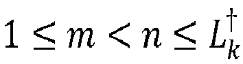
- Analogously, the list

elements 


- In the formula to follow, we interpret the Λ operator to represent logical AND, the ∥ operator to represent logical OR, and the ¬ operator to represent logical negation. There is a set of variables whose values can be computed directly from the inputs yk and d̂k , which are referred to as 'independent' calculations since they do not depend on the state metrics. In practice, this means that they can be pre-computed, which removes them from the critical path.
- There are also dependent variables that cannot be determined unless the state metrics are known; they are referred to as "dependent" variables determined by "dependent" calculations using state metrics. The variables include:


- In order to optimize the power consumption and area of the implementation, we wish to minimize the sum of the lengths of the lists


- when true, list lengths are adjusted dynamically;
- when false,

-
Figures 4A-C are simplified diagrams illustrating updating trellis metrics using multiplexors according to embodiments of the present invention. This diagram is merely an example, which should not unduly limit the scope of the claims. One of ordinary skill in the art would recognize many variations, alternatives, and modifications. As shown inFigure 4A , a trellis path (e.g., trellis 300) is navigated usingmux selectors Operators sign operators lists 

Figure 4B . Variables

mux selectors 

lists 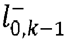

Figure 4B . Variables

mux selectors 

- As an example, below are the trellis output:
- If


- If


- If


- If


- In various implementations, the ee-buffer is configured as a part of a soft decoder (e.g.,
decoder 213 inFigure 2 . For example, the soft decoder is configured to perform the following steps: - 1. Find L elements in the ee-buffer with the smallest metrics, and denote these by ε;
- 2. For each of the L elements in ε, flip the corresponding PAM symbols and compute syndrome. If syndrome is zero, check if the associated metric is better than the current best;
- 3. For each pair of elements in ε, flip the corresponding PAM symbols and compute syndrome. If syndrome is zero and the error events are non-overlapping, check if the associated metric (i.e., the sum of the metrics from each element of the pair) is better than the current best metric; and
- 4. Output the bits associated with the valid codeword with the best metric. If no valid codewords are determined, output the hard decisions from
Demapper 203. - It is to be appreciated that soft decoders can be implemented in various ways, as described in further detail below.
- As an example, the process of updating list lengths is determined using the process below:

- As an example, the above process of updating list lengths is executed by
module 500 inFigure 5A , whereinmux selector 503 selects its output based on variables w0w1 , which implements the "if' conditions. - List update equations, which may be implemented with mux selectors illustrated in
Figures 5B and5C , may be used to update the pair of lists for the trellis. For example, at every time step k, lists

- As an example, the list

mux selectors Figure 5B .
- Similarly, the list

mux selectors Figure 5C :
- There are various implementation considerations. For example, the appearance of D in the list update equations arises from the fact that when a path merging into the '0' state with negative metric is determined, future error events emerging from the '0 ' state need to be preferred relative to any surviving error events that did not pass through the same '0' state.
- When the input decisions d̂k are the maximum likelihood decisions, then D = 0 (all error events will have non-negative metrics). This reduces the critical path of the list update equations in estimation-based applications with a first detector that generates MLSD decisions. In this case, the critical path may then be dominated by the calculation of q, which is only required if dynamic list lengths are computed (i.e., LD = 1).
- At each time k, each of the L paths that were unterminated at time k - 1 can merge into the error-free state; the corresponding Nyquist error events terminate at time k. The path metrics associated with the terminating error events can be calculated in various ways. For example, for each element in

Equation 4 below:
- Similarly for each element in


- In principle, a list Ek can be stored for each time k that consists of some subset of the paths terminating at time k. Each element of Ek includes the start index, the sign of the start of the Nyquist error, and the metric of the terminating path; the terminating index of the Nyquist error event is implied. Note that the number of elements in the Ek need not be equal to L. One of the approaches to minimize complexity is to add to Ek the elements from either the paths emanating from the " +1" or the "-1 " error state, but not both. The choice of which set of paths to add can be determined by comparing the metric of the most likely error event from each state.
- The proposed Nyquist-error-based soft-decision FEC decoder (e.g.,
decoder 213 inFigure 2 ) only requires that the N most likely Nyquist error events over the span of the FEC codeword be determined. This can be accomplished by tracing-through the Ek for k in the span of the FEC codeword boundaries, and storing a list of the N error events with the smallest metrics. In practice, this consists of merging sorted lists at each k, discarding all but the N most likely at each k. It is to be noted that calculation of the trellis outputs (and any post-processing) is decoupled from the list update equations, and thus does not contribute to their critical path. - There are certain special implementations of the Nyquist estimation process described above. First, when L =1 and LD = 1, implementation complexity is at a minimum, but the performance is degraded for α close to unity. The degradation in performance is eliminated when L = 2 and LD = 0. However, note that the critical path of the resulting implementation may be increased, due to the appearance of D in the update equations, which in turn implies that a difference of path metrics must be computed. In the special case of L = 1 and LD = 1, the difference of path metrics reduces to zero (since it is the difference of the only listed metric with itself), and thus the critical path is shorter. In practice, the degradation in performance due to forcing D=0 may be minor, in which case the increase in critical path can be avoided. In both cases, a trellis trace-back scheme can be used to generate the most likely error sequence.
- In certain implementations, a maximum sequence likelihood or a maximum symbol likelihood can be performed by post-processing ε. In the case of maximum symbol likelihood, an input decision d̂k is flipped if its index falls within the span of a Nyquist error event for which the metric is negative; if it falls within the span of multiple Nyquist error events with negative metrics, then it should be flipped based on the error event with the smallest metric. In the case of maximum sequence likelihood, ε is post-processed to determine the set of non-overlapping Nyquist error events (with negative metrics) whose metrics sum to the smallest metric. The resulting set of error events is used to flip the corresponding values of d̂k . A greedy algorithm (closely approximating the optimal post-processor) consists of purging ε from any Nyquist error events that intersect with the most likely Nyquist error event, and then similarly purging with respect to the second most likely remaining path, and so on.
- It is to be appreciated that Nyquist-error-based soft-decision FEC decoder only requires that the N most likely Nyquist error events (over the span of the FEC codeword) be determined (i.e., the list ε described above). More generally, the trellis outputs Ek (or the compressed list ε) can be used to directly calculate an approximation to the maximum a posteriori probability (MAP) of each symbol. The MAP estimation (in log-likelihood form) of the transmitted symbol at time k can be expressed in Equation 6 below:

- An approximation of Equation 6 is expressed in Equation 7 below:

- The Nyquist error estimation techniques, as implemented in various embodiments, can be generalized to applications with nonlinearities; the error generation block and the equations that describe the branch metrics (i.e., A+, A-, B, C+, C-) are modeled for the applications. For example,
Equation 8 below describes a generalized channel model:
- In various implementations, Nyquist error estimation is implemented for a system that uses PAM for communication. For simplicity of the description, it is assumed that the system implements PAM-4, although the approach applies to any PAM-N. It is useful to differentiate two types of non-linearities. First, we assume the following:


- For PAM-4, a(k) = 0 when d̂ = 0, or when d̂= 1 and yk < 0; a(k) = 1 when d̂= 1 and yk > 0, or when d̂= 2 and yk < 0; a(k) = 2 when d̂= 2 and yk > 0, or when d̂= 3. Analogously, γ 0 = δ 0/2, γ 1 = (δ 1 - δ 0)/2, and γ 1 = -δ 1/2. The error signal may be described in
Equation 10 below:
- The resulting generalized form of the 'independent' calculations are provided below:


- In various implementations, approximations may be applied to simplify the calculation of the variable β.
- As explained above, a soft-decision FEC decoder (e.g.,
decoder 213 inFigure 2 ) processes the detector output decisions dk , the list ε of the N most likely error events, and optionally the error generator output. Each element of the list ε provides the starting index, ending index, the polarity of starting error, and the metric of the Nyquist error event. - Similar in spirit to a classic Chase decoder, a Nyquist-error-based soft-decision decoder generates a set of candidate decoder inputs, and each candidate is decoded by a hard-decision decoder. For each candidate, the reliability of the decoded codeword is calculated by determining the difference between the detector output decisions d̂ and the decoded codeword decisions. Specifically, the difference is expressed in terms of one or more Nyquist error events, and an analytical expression may be used to calculate the resulting decoder metric. The output of the Nyquist-error-based soft-decision FEC decoder is the codeword with the smallest metric.
- Based on the N Nyquist error events enumerated in ε, a set of hard-decision decoder input candidates can be generated by flipping the detector output decisions d̂ (and correspondingly performing the receiver demapping on the resulting decisions) corresponding to different combinations of error events. For example, N candidate codewords may be generated, each corresponding to a single error event in ε. Similarly, the N(N-1)/2 candidate codewords may be generated, each corresponding to a unique pair of error events in ε, and so on for three or more error events per codeword. It is also possible to consider flipping individual bits (e.g., either the error at the start or the end of an error event) from any subset of error events.
- Based on the decoder output for each candidate, it is necessary to determine a codeword metric. First, the difference between the detector output decisions d̂ and the decoded codeword decisions must be expressed in terms of a set of Nyquist error events (i.e., for each event, the indices of the start, ks , and end, ke ). The candidate codeword metric is then the sum of the metrics of its constituent Nyquist error events. Note that a Nyquist error event is only valid if the resulting output decisions result in a valid PAM-N sequence, and that any invalid error event results in rejection of the candidate codeword. Each 'valid' Nyquist error event has a metric M calculated using
Equation 11 below:
- Excellent performance is possible even when the FEC decoder is only used to perform error detection (i.e., the error-correcting capacity of the FEC decoder is not exploited). In this case, the Chase-style decoder is further restricted to only flip non-overlapping Nyquist error events, i.e., unlike the more general case, it does not consider flipping only the first or only the last position in a Nyquist error event.
- In addition to the savings inherent in only performing syndrome calculation, a further significant advantage is that the calculation of the codeword metric (when the syndrome is satisfied) is simply the sum of the metrics of the associated Nyquist error events (i.e., no calculation of error event metrics is required), and the error generator output can be discarded once the Nyquist error-event list has been computed.
-
Figures 6A-E are plots illustrating the performance of a Nyquist error estimator at different settings, for a range of α, using the first encoding scheme with a (68; 60) extended-Hamming code (for parity generation) and with precoding disabled. For the detector, a Nyquist-error-based sequence detector (with L = 2 and LD = 0) is used to post-process the output of a decision-feedback equalizer. For the Nyquist-error-based sequence estimator,Figures 6A-E show the performance for different settings of L and LD. More specifically,plot 601 inFigure 6A corresponds to a PAM4 setting with α=0.5;plot 602 inFigure 6B corresponds to a PAM4 setting with α=0.625;plot 603 inFigure 6C corresponds to a PAM4 setting with α=0.75;plot 604 inFigure 6D corresponds to a PAM4 setting with α=0.875; andplot 605 inFigure 6E corresponds to a PAM4 setting with α=1. The Nyquist-error-based soft-decision FEC decoder operates in error-detection-only mode and processes an input list of N = 12 Nyquist error events, considering all possibilities of 1 or 2 error events within the span of the codeword. - While the above is a full description of the specific embodiments, various modifications, alternative constructions and equivalents may be used. Therefore, the above description and illustrations should not be taken as limiting the scope of the present invention which is defined by the appended claims.
- The following is a list of further preferred embodiments of the invention:
- Embodiment 1: A receiver device comprising:
- an equalizer configured to provide equalized signals based on received signals;
- a detector configured to generate a first decision based on the equalized signals;
- a demapper configured to generate a first output based at least on the first decision;
- an error correction module configured to generate a second output based on at least the first decision and an error indicator, the error correction module comprising a Nyquist error estimator for generating the error indicator based at least on the equalized signals and the first decision; and
- a syndrome calculator configured to calculator a syndrome value based on the first output; and
- a selector configured to select between the first output and the second output based at least on the syndrome value.
- Embodiment 2: The device of
embodiment 1 where the equalizer comprises a feedforward equalizer. - Embodiment 3: The device of
embodiment 1 wherein the error correction module is activated by a non-zero syndrome value. - Embodiment 4: The device of
embodiment 1 wherein the error correction module further comprises:- an error generator configured to generate an intermediate value based at least on the equalized signals and the first decision; and
- a decoder configured to generate the second output based at least on the error indictor and the first decision;
- wherein the Nyquist error estimator is configured to use the intermediate value in generating the error indicator.
- Embodiment 5: The device of
embodiment 4 wherein the decoder is configured to perform demapping functions. - Embodiment 6: The device of
embodiment 4 wherein the Nyquist error estimator is an error-event list trellis-based processor. - Embodiment 7: The device of
embodiment 1 wherein the detector comprises a maximum-likelihood sequence detector. - Embodiment 8: The device of
embodiment 1 wherein the detector comprises a decision feedback-equalizer. - Embodiment 9: The device of
embodiment 1 wherein the first decision is associated with an FEC codeword. - Embodiment 10: The device of
embodiment 1 wherein the demapper comprises an inverse precoder. - Embodiment 11: An error correction device comprising:
- an error generator configured to generate an intermediate signal based on least an input signal and a first decision, the first decision being based on the input signal;
- a Nyquist error estimator configured to generate an error indicator using at least the intermediate signal and the first decision; and
- a decoder configured to generate an output based at least on the error indictor and the first decision;
- wherein the Nyquist error estimator is an error-event list trellis-based processor, and Nyquist error estimator updates a set of lists recursively.
- Embodiment 12: The device of
embodiment 11 wherein the decoder comprises a demapper. - Embodiment 13: The device of
embodiment 11 wherein the set of lists comprises a first list, the first list comprising a time index, an error sign, and a path metric. - Embodiment 14: The device of
embodiment 13 wherein the first list is associated with a dynamic list length. - Embodiment 15: The device of
embodiment 11 wherein the Nyquist error estimator comprises multiplexers for implementing the trellis. - Embodiment 16: A method for processing received data comprising:
- receiving an input signal;
- equalizing the input signal to provide an equalized signal;
- generating a first decision based the equalized signal;
- demapping the first decision to generate a first output;
- determining a syndrome value associated with the first output;
generating a second output using an error correction process if the syndrome value is non-zero, the error correction process including a Nyquist error estimation process; and - selecting between the first output and the second output using the syndrome value.
- Embodiment 17: The method of embodiment 16 wherein the error correction process comprises generating an intermediate error value using the equalized signal and the first decision.
- Embodiment 18: The method of embodiment 17 wherein the Nyquist error estimation process comprises traversing an error-event trellis using a set of lists.
- Embodiment 19: The method of embodiment 18 further comprising generating the set of lists, the set of lists being associated with dynamic list lengths.
- Embodiment 20: The method of embodiment 16 further comprising performing soft decoding using a result of the Nyquist error estimation process and the first decision.
- Embodiment 21: A transmitter device comprising:
- an RS symbol interleaver configured to generate RS symbols from RS codewords;
- a first PAM-n mapper configured to generate a first set of PAM-n symbols based on the RS symbols;
- a bit selector module configured to select a subset of bits from the first set of PAM-n symbols;
- a parity generator configured to generate parity bits using the subset of bits;
- a second PAM-n mapper configured to get a second set of PAM-n symbols using the parity bits;
- a concatenation module configured to concatenate the first set of PAM-n symbols and the second set of PAM-n symbols to generate a concatenated data steam; and
- a pilot symbol insertion module configured to insert pilot symbols to the concatenated data stream.
- an RS symbol interleaver configured to generate RS symbols from RS codewords;
- Embodiment 22: The transmitter device of embodiment 21 further comprising a modulo-N precoder configured to process the concatenated data stream.
- Embodiment 23: The transmitter device of embodiment 21 further comprising a modulo-N precoder configured to process the first set of PAM-n symbols.
- Embodiment 24: The transmitter device of embodiment 21 wherein the pilot symbols indicate start and end of trellis processes.
Claims (15)
- A receiver device comprising:an equalizer configured to provide equalized signals based on received signals;a detector configured to generate a first decision based on the equalized signals;a demapper configured to generate a first output based at least on the first decision;an error correction module configured to generate a second output based on at least the first decision and an error indicator, the error correction module comprising a Nyquist error estimator for generating the error indicator based at least on the equalized signals and the first decision; anda syndrome calculator configured to calculator a syndrome value based on the first output; anda selector configured to select between the first output and the second output based at least on the syndrome value.
- The device of claim 1 where the equalizer comprises a feedforward equalizer.
- The device of claim 1 or 2 wherein the error correction module is activated by a non-zero syndrome value.
- The device of one of claims 1 to 3 wherein the error correction module further comprises:an error generator configured to generate an intermediate value based at least on the equalized signals and the first decision; anda decoder configured to generate the second output based at least on the error indictor and the first decision;wherein the Nyquist error estimator is configured to use the intermediate value in generating the error indicator.
- The device of claim 4 wherein the decoder is configured to perform demapping functions.
- The device of claim 4 wherein the Nyquist error estimator is an error-event list trellis-based processor.
- The device of one of claims 1 to 6 wherein the detector comprises a maximum-likelihood sequence detector; orwherein the detector comprises a decision feedback-equalizer; orwherein the first decision is associated with an FEC codeword; orwherein the demapper comprises an inverse precoder.
- An error correction device comprising:an error generator configured to generate an intermediate signal based on least an input signal and a first decision, the first decision being based on the input signal;a Nyquist error estimator configured to generate an error indicator using at least the intermediate signal and the first decision; anda decoder configured to generate an output based at least on the error indictor and the first decision;wherein the Nyquist error estimator is an error-event list trellis-based processor, and Nyquist error estimator updates a set of lists recursively.
- The device of claim 8 wherein the decoder comprises a demapper.
- The device of claim 8 or 9 wherein the set of lists comprises a first list, the first list comprising a time index, an error sign, and a path metric; and/or
wherein the first list is associated with a dynamic list length. - The device of one of claims 8 to 10 wherein the Nyquist error estimator comprises multiplexers for implementing the trellis.
- A method for processing received data comprising:receiving an input signal;equalizing the input signal to provide an equalized signal;generating a first decision based the equalized signal;demapping the first decision to generate a first output;determining a syndrome value associated with the first output;generating a second output using an error correction process if the syndrome value is non-zero, the error correction process including a Nyquist error estimation process; andselecting between the first output and the second output using the syndrome value.
- The method of claim 12 wherein the error correction process comprises generating an intermediate error value using the equalized signal and the first decision; and/orwherein the Nyquist error estimation process comprises traversing an error-event trellis using a set of lists; and/orfurther comprising generating the set of lists, the set of lists being associated with dynamic list lengths; orfurther comprising performing soft decoding using a result of the Nyquist error estimation process and the first decision.
- A transmitter device comprising:an RS symbol interleaver configured to generate RS symbols from RS codewords;a first PAM-n mapper configured to generate a first set of PAM-n symbols based on the RS symbols;a bit selector module configured to select a subset of bits from the first set of PAM-n symbols;a parity generator configured to generate parity bits using the subset of bits;a second PAM-n mapper configured to get a second set of PAM-n symbols using the parity bits;a concatenation module configured to concatenate the first set of PAM-n symbols and the second set of PAM-n symbols to generate a concatenated data steam; anda pilot symbol insertion module configured to insert pilot symbols to the concatenated data stream.
- The transmitter device of claim 14 further comprising a modulo-N precoder configured to process the concatenated data stream; orfurther comprising a modulo-N precoder configured to process the first set of PAM-n symbols; orwherein the pilot symbols indicate start and end of trellis processes.
Applications Claiming Priority (1)
| Application Number | Priority Date | Filing Date | Title |
|---|---|---|---|
| US17/244,259 US11368170B1 (en) | 2021-04-29 | 2021-04-29 | Systems and methods for Nyquist error correction |
Publications (3)
| Publication Number | Publication Date |
|---|---|
| EP4092939A2 true EP4092939A2 (en) | 2022-11-23 |
| EP4092939A3 EP4092939A3 (en) | 2023-02-01 |
| EP4092939B1 EP4092939B1 (en) | 2024-11-06 |
Family
ID=81850234
Family Applications (1)
| Application Number | Title | Priority Date | Filing Date |
|---|---|---|---|
| EP22170597.3A Active EP4092939B1 (en) | 2021-04-29 | 2022-04-28 | Systems and methods for nyquist error correction |
Country Status (3)
| Country | Link |
|---|---|
| US (2) | US11368170B1 (en) |
| EP (1) | EP4092939B1 (en) |
| CN (1) | CN115276898A (en) |
Citations (1)
| Publication number | Priority date | Publication date | Assignee | Title |
|---|---|---|---|---|
| US10404289B1 (en) | 2018-05-31 | 2019-09-03 | Inphi Corporation | Maximum likelihood error detection for decision feedback equalizers with PAM modulation |
Family Cites Families (13)
| Publication number | Priority date | Publication date | Assignee | Title |
|---|---|---|---|---|
| US5457704A (en) * | 1993-05-21 | 1995-10-10 | At&T Ipm Corp. | Post processing method and apparatus for symbol reliability generation |
| US5848106A (en) * | 1996-12-16 | 1998-12-08 | Ericsson, Inc. | Receiver decoder circuitry, and associated method, for decoding an encoded signal |
| US6029264A (en) * | 1997-04-28 | 2000-02-22 | The Trustees Of Princeton University | System and method for error correcting a received data stream in a concatenated system |
| US5926490A (en) * | 1997-05-23 | 1999-07-20 | Cirrus Logic, Inc. | Sampled amplitude read channel employing a remod/demod sequence detector guided by an error syndrome |
| JP3889286B2 (en) * | 2002-01-31 | 2007-03-07 | 三菱電機株式会社 | Decoding method, decoding apparatus, and digital transmission system |
| US7231575B2 (en) * | 2002-04-01 | 2007-06-12 | Intel Corporation | Apparatus for iterative hard-decision forward error correction decoding |
| US7158568B2 (en) * | 2002-04-17 | 2007-01-02 | Thomson Licensing | Equalizer/forward error correction automatic mode selector |
| US7725800B2 (en) * | 2005-08-05 | 2010-05-25 | Hitachi Global Stroage Technologies Netherlands, B.V. | Decoding techniques for correcting errors using soft information |
| US8001449B2 (en) * | 2007-07-27 | 2011-08-16 | Yao-Chung Chang | Syndrome-error mapping method for decoding linear and cyclic codes |
| US8205144B1 (en) * | 2008-10-13 | 2012-06-19 | Marvell International Ltd. | Error event processing methods and systems |
| US8656257B1 (en) * | 2012-01-11 | 2014-02-18 | Pmc-Sierra Us, Inc. | Nonvolatile memory controller with concatenated error correction codes |
| US9088447B1 (en) * | 2014-03-21 | 2015-07-21 | Mitsubishi Electric Research Laboratories, Inc. | Non-coherent transmission and equalization in doubly-selective MIMO channels |
| US10084481B2 (en) * | 2014-12-18 | 2018-09-25 | Apple Inc. | GLDPC soft decoding with hard decision inputs |
-
2021
- 2021-04-29 US US17/244,259 patent/US11368170B1/en active Active
-
2022
- 2022-04-28 EP EP22170597.3A patent/EP4092939B1/en active Active
- 2022-04-29 CN CN202210474701.3A patent/CN115276898A/en active Pending
- 2022-05-31 US US17/828,850 patent/US11916574B2/en active Active
Patent Citations (2)
| Publication number | Priority date | Publication date | Assignee | Title |
|---|---|---|---|---|
| US10404289B1 (en) | 2018-05-31 | 2019-09-03 | Inphi Corporation | Maximum likelihood error detection for decision feedback equalizers with PAM modulation |
| US10637512B2 (en) | 2018-05-31 | 2020-04-28 | Inphi Corporation | Maximum likelihood error detection for decision feedback equalizers with PAM modulation |
Also Published As
| Publication number | Publication date |
|---|---|
| US11368170B1 (en) | 2022-06-21 |
| EP4092939B1 (en) | 2024-11-06 |
| CN115276898A (en) | 2022-11-01 |
| EP4092939A3 (en) | 2023-02-01 |
| US11916574B2 (en) | 2024-02-27 |
| US20220376712A1 (en) | 2022-11-24 |
Similar Documents
| Publication | Publication Date | Title |
|---|---|---|
| US7206363B2 (en) | Method and apparatus for delayed recursion decoder | |
| EP3577765B1 (en) | Soft output decoding of polar codes using successive cancelation list (scl) decoding | |
| Tuchler et al. | Minimum mean squared error equalization using a priori information | |
| US5757821A (en) | Method and apparatus for detecting communication signals having unequal error protection | |
| EP1004181B1 (en) | Communications systems and methods employing selective recursive decoding | |
| US6178209B1 (en) | Method of estimating trellis encoded symbols utilizing simplified trellis decoding | |
| US20030108113A1 (en) | Implementing reduced-state viterbi detectors | |
| US8542724B1 (en) | Iterative joint minimum mean square error decision feedback equalizer and turbo decoder | |
| CN101345601B (en) | Interpretation method and decoder | |
| JP5868509B2 (en) | Receiver and communication method | |
| KR100988225B1 (en) | Apparatus and method for providing trellis decoded data, and equalizer / trellis decoder system | |
| Mahadevan et al. | Impact of DFE on soft-input LDPC decoding for 50G PON | |
| US5822340A (en) | Method for decoding data signals using fixed-length decision window | |
| US6587987B1 (en) | Method and apparatus for extracting reliability information from partial response channels | |
| EP4092939B1 (en) | Systems and methods for nyquist error correction | |
| US6782060B2 (en) | Method and apparatus for generating reliability information for channel decoding in a radio receiver | |
| CN115699595B (en) | Equalizing method and device | |
| US7136413B2 (en) | Method and apparatus for generation of reliability information with diversity | |
| CN103685105A (en) | Method and device for outputting soft information in maximum likelihood balance | |
| US12592722B2 (en) | Soft information generation for concatenated forward error correction in digiral signal processing | |
| US7224724B2 (en) | Reduced alphabet equalizer using iterative equalization | |
| Lee et al. | Analysis of linear turbo equalizer via EXIT chart | |
| Bodet et al. | The Benefit of Decoder-Provided Pilots in Highly Dynamic Channels | |
| Myburgh et al. | A primer on equalization, decoding and non-iterative joint equalization and decoding | |
| Myburgh | Low complexity turbo equalization using superstructures |
Legal Events
| Date | Code | Title | Description |
|---|---|---|---|
| PUAI | Public reference made under article 153(3) epc to a published international application that has entered the european phase |
Free format text: ORIGINAL CODE: 0009012 |
|
| STAA | Information on the status of an ep patent application or granted ep patent |
Free format text: STATUS: THE APPLICATION HAS BEEN PUBLISHED |
|
| AK | Designated contracting states |
Kind code of ref document: A2 Designated state(s): AL AT BE BG CH CY CZ DE DK EE ES FI FR GB GR HR HU IE IS IT LI LT LU LV MC MK MT NL NO PL PT RO RS SE SI SK SM TR |
|
| PUAL | Search report despatched |
Free format text: ORIGINAL CODE: 0009013 |
|
| AK | Designated contracting states |
Kind code of ref document: A3 Designated state(s): AL AT BE BG CH CY CZ DE DK EE ES FI FR GB GR HR HU IE IS IT LI LT LU LV MC MK MT NL NO PL PT RO RS SE SI SK SM TR |
|
| RIC1 | Information provided on ipc code assigned before grant |
Ipc: H03M 13/33 20060101ALI20221223BHEP Ipc: H03M 13/19 20060101ALI20221223BHEP Ipc: H03M 13/15 20060101ALI20221223BHEP Ipc: H03M 13/29 20060101ALI20221223BHEP Ipc: H03M 13/00 20060101ALI20221223BHEP Ipc: H04L 1/00 20060101AFI20221223BHEP |
|
| STAA | Information on the status of an ep patent application or granted ep patent |
Free format text: STATUS: REQUEST FOR EXAMINATION WAS MADE |
|
| 17P | Request for examination filed |
Effective date: 20230323 |
|
| RBV | Designated contracting states (corrected) |
Designated state(s): AL AT BE BG CH CY CZ DE DK EE ES FI FR GB GR HR HU IE IS IT LI LT LU LV MC MK MT NL NO PL PT RO RS SE SI SK SM TR |
|
| P01 | Opt-out of the competence of the unified patent court (upc) registered |
Effective date: 20230509 |
|
| RIC1 | Information provided on ipc code assigned before grant |
Ipc: H03M 13/33 20060101ALI20240426BHEP Ipc: H03M 13/19 20060101ALI20240426BHEP Ipc: H03M 13/15 20060101ALI20240426BHEP Ipc: H03M 13/29 20060101ALI20240426BHEP Ipc: H03M 13/00 20060101ALI20240426BHEP Ipc: H04L 1/00 20060101AFI20240426BHEP |
|
| GRAP | Despatch of communication of intention to grant a patent |
Free format text: ORIGINAL CODE: EPIDOSNIGR1 |
|
| STAA | Information on the status of an ep patent application or granted ep patent |
Free format text: STATUS: GRANT OF PATENT IS INTENDED |
|
| INTG | Intention to grant announced |
Effective date: 20240605 |
|
| GRAS | Grant fee paid |
Free format text: ORIGINAL CODE: EPIDOSNIGR3 |
|
| GRAA | (expected) grant |
Free format text: ORIGINAL CODE: 0009210 |
|
| STAA | Information on the status of an ep patent application or granted ep patent |
Free format text: STATUS: THE PATENT HAS BEEN GRANTED |
|
| AK | Designated contracting states |
Kind code of ref document: B1 Designated state(s): AL AT BE BG CH CY CZ DE DK EE ES FI FR GB GR HR HU IE IS IT LI LT LU LV MC MK MT NL NO PL PT RO RS SE SI SK SM TR |
|
| REG | Reference to a national code |
Ref country code: GB Ref legal event code: FG4D |
|
| REG | Reference to a national code |
Ref country code: CH Ref legal event code: EP |
|
| REG | Reference to a national code |
Ref country code: DE Ref legal event code: R096 Ref document number: 602022007363 Country of ref document: DE |
|
| REG | Reference to a national code |
Ref country code: IE Ref legal event code: FG4D |
|
| REG | Reference to a national code |
Ref country code: LT Ref legal event code: MG9D |
|
| REG | Reference to a national code |
Ref country code: NL Ref legal event code: MP Effective date: 20241106 |
|
| PG25 | Lapsed in a contracting state [announced via postgrant information from national office to epo] |
Ref country code: IS Free format text: LAPSE BECAUSE OF FAILURE TO SUBMIT A TRANSLATION OF THE DESCRIPTION OR TO PAY THE FEE WITHIN THE PRESCRIBED TIME-LIMIT Effective date: 20250306 Ref country code: PT Free format text: LAPSE BECAUSE OF FAILURE TO SUBMIT A TRANSLATION OF THE DESCRIPTION OR TO PAY THE FEE WITHIN THE PRESCRIBED TIME-LIMIT Effective date: 20250306 Ref country code: HR Free format text: LAPSE BECAUSE OF FAILURE TO SUBMIT A TRANSLATION OF THE DESCRIPTION OR TO PAY THE FEE WITHIN THE PRESCRIBED TIME-LIMIT Effective date: 20241106 |
|
| PG25 | Lapsed in a contracting state [announced via postgrant information from national office to epo] |
Ref country code: FI Free format text: LAPSE BECAUSE OF FAILURE TO SUBMIT A TRANSLATION OF THE DESCRIPTION OR TO PAY THE FEE WITHIN THE PRESCRIBED TIME-LIMIT Effective date: 20241106 Ref country code: NL Free format text: LAPSE BECAUSE OF FAILURE TO SUBMIT A TRANSLATION OF THE DESCRIPTION OR TO PAY THE FEE WITHIN THE PRESCRIBED TIME-LIMIT Effective date: 20241106 |
|
| REG | Reference to a national code |
Ref country code: AT Ref legal event code: MK05 Ref document number: 1740543 Country of ref document: AT Kind code of ref document: T Effective date: 20241106 |
|
| PG25 | Lapsed in a contracting state [announced via postgrant information from national office to epo] |
Ref country code: BG Free format text: LAPSE BECAUSE OF FAILURE TO SUBMIT A TRANSLATION OF THE DESCRIPTION OR TO PAY THE FEE WITHIN THE PRESCRIBED TIME-LIMIT Effective date: 20241106 |
|
| PG25 | Lapsed in a contracting state [announced via postgrant information from national office to epo] |
Ref country code: ES Free format text: LAPSE BECAUSE OF FAILURE TO SUBMIT A TRANSLATION OF THE DESCRIPTION OR TO PAY THE FEE WITHIN THE PRESCRIBED TIME-LIMIT Effective date: 20241106 |
|
| PG25 | Lapsed in a contracting state [announced via postgrant information from national office to epo] |
Ref country code: NO Free format text: LAPSE BECAUSE OF FAILURE TO SUBMIT A TRANSLATION OF THE DESCRIPTION OR TO PAY THE FEE WITHIN THE PRESCRIBED TIME-LIMIT Effective date: 20250206 |
|
| PG25 | Lapsed in a contracting state [announced via postgrant information from national office to epo] |
Ref country code: GR Free format text: LAPSE BECAUSE OF FAILURE TO SUBMIT A TRANSLATION OF THE DESCRIPTION OR TO PAY THE FEE WITHIN THE PRESCRIBED TIME-LIMIT Effective date: 20250207 Ref country code: LV Free format text: LAPSE BECAUSE OF FAILURE TO SUBMIT A TRANSLATION OF THE DESCRIPTION OR TO PAY THE FEE WITHIN THE PRESCRIBED TIME-LIMIT Effective date: 20241106 Ref country code: AT Free format text: LAPSE BECAUSE OF FAILURE TO SUBMIT A TRANSLATION OF THE DESCRIPTION OR TO PAY THE FEE WITHIN THE PRESCRIBED TIME-LIMIT Effective date: 20241106 |
|
| PG25 | Lapsed in a contracting state [announced via postgrant information from national office to epo] |
Ref country code: PL Free format text: LAPSE BECAUSE OF FAILURE TO SUBMIT A TRANSLATION OF THE DESCRIPTION OR TO PAY THE FEE WITHIN THE PRESCRIBED TIME-LIMIT Effective date: 20241106 |
|
| PG25 | Lapsed in a contracting state [announced via postgrant information from national office to epo] |
Ref country code: RS Free format text: LAPSE BECAUSE OF FAILURE TO SUBMIT A TRANSLATION OF THE DESCRIPTION OR TO PAY THE FEE WITHIN THE PRESCRIBED TIME-LIMIT Effective date: 20250206 |
|
| PG25 | Lapsed in a contracting state [announced via postgrant information from national office to epo] |
Ref country code: SM Free format text: LAPSE BECAUSE OF FAILURE TO SUBMIT A TRANSLATION OF THE DESCRIPTION OR TO PAY THE FEE WITHIN THE PRESCRIBED TIME-LIMIT Effective date: 20241106 |
|
| PGFP | Annual fee paid to national office [announced via postgrant information from national office to epo] |
Ref country code: DE Payment date: 20250428 Year of fee payment: 4 |
|
| PG25 | Lapsed in a contracting state [announced via postgrant information from national office to epo] |
Ref country code: DK Free format text: LAPSE BECAUSE OF FAILURE TO SUBMIT A TRANSLATION OF THE DESCRIPTION OR TO PAY THE FEE WITHIN THE PRESCRIBED TIME-LIMIT Effective date: 20241106 |
|
| PG25 | Lapsed in a contracting state [announced via postgrant information from national office to epo] |
Ref country code: EE Free format text: LAPSE BECAUSE OF FAILURE TO SUBMIT A TRANSLATION OF THE DESCRIPTION OR TO PAY THE FEE WITHIN THE PRESCRIBED TIME-LIMIT Effective date: 20241106 |
|
| PGFP | Annual fee paid to national office [announced via postgrant information from national office to epo] |
Ref country code: FR Payment date: 20250424 Year of fee payment: 4 |
|
| PG25 | Lapsed in a contracting state [announced via postgrant information from national office to epo] |
Ref country code: RO Free format text: LAPSE BECAUSE OF FAILURE TO SUBMIT A TRANSLATION OF THE DESCRIPTION OR TO PAY THE FEE WITHIN THE PRESCRIBED TIME-LIMIT Effective date: 20241106 |
|
| PG25 | Lapsed in a contracting state [announced via postgrant information from national office to epo] |
Ref country code: SK Free format text: LAPSE BECAUSE OF FAILURE TO SUBMIT A TRANSLATION OF THE DESCRIPTION OR TO PAY THE FEE WITHIN THE PRESCRIBED TIME-LIMIT Effective date: 20241106 |
|
| PG25 | Lapsed in a contracting state [announced via postgrant information from national office to epo] |
Ref country code: CZ Free format text: LAPSE BECAUSE OF FAILURE TO SUBMIT A TRANSLATION OF THE DESCRIPTION OR TO PAY THE FEE WITHIN THE PRESCRIBED TIME-LIMIT Effective date: 20241106 |
|
| PG25 | Lapsed in a contracting state [announced via postgrant information from national office to epo] |
Ref country code: IT Free format text: LAPSE BECAUSE OF FAILURE TO SUBMIT A TRANSLATION OF THE DESCRIPTION OR TO PAY THE FEE WITHIN THE PRESCRIBED TIME-LIMIT Effective date: 20241106 |
|
| REG | Reference to a national code |
Ref country code: DE Ref legal event code: R097 Ref document number: 602022007363 Country of ref document: DE |
|
| PG25 | Lapsed in a contracting state [announced via postgrant information from national office to epo] |
Ref country code: SE Free format text: LAPSE BECAUSE OF FAILURE TO SUBMIT A TRANSLATION OF THE DESCRIPTION OR TO PAY THE FEE WITHIN THE PRESCRIBED TIME-LIMIT Effective date: 20241106 |
|
| PLBE | No opposition filed within time limit |
Free format text: ORIGINAL CODE: 0009261 |
|
| STAA | Information on the status of an ep patent application or granted ep patent |
Free format text: STATUS: NO OPPOSITION FILED WITHIN TIME LIMIT |
|
| 26N | No opposition filed |
Effective date: 20250807 |
|
| REG | Reference to a national code |
Ref country code: CH Ref legal event code: H13 Free format text: ST27 STATUS EVENT CODE: U-0-0-H10-H13 (AS PROVIDED BY THE NATIONAL OFFICE) Effective date: 20251125 |
|
| PG25 | Lapsed in a contracting state [announced via postgrant information from national office to epo] |
Ref country code: LU Free format text: LAPSE BECAUSE OF NON-PAYMENT OF DUE FEES Effective date: 20250428 |
|
| PG25 | Lapsed in a contracting state [announced via postgrant information from national office to epo] |
Ref country code: MC Free format text: LAPSE BECAUSE OF FAILURE TO SUBMIT A TRANSLATION OF THE DESCRIPTION OR TO PAY THE FEE WITHIN THE PRESCRIBED TIME-LIMIT Effective date: 20241106 |
|
| REG | Reference to a national code |
Ref country code: BE Ref legal event code: MM Effective date: 20250430 |
|
| PG25 | Lapsed in a contracting state [announced via postgrant information from national office to epo] |
Ref country code: BE Free format text: LAPSE BECAUSE OF NON-PAYMENT OF DUE FEES Effective date: 20250430 |
|
| PG25 | Lapsed in a contracting state [announced via postgrant information from national office to epo] |
Ref country code: CH Free format text: LAPSE BECAUSE OF NON-PAYMENT OF DUE FEES Effective date: 20250430 |
|
| PG25 | Lapsed in a contracting state [announced via postgrant information from national office to epo] |
Ref country code: IE Free format text: LAPSE BECAUSE OF NON-PAYMENT OF DUE FEES Effective date: 20250428 |