EP4092898A1 - Modular solid-state power converter and fault protector - Google Patents
Modular solid-state power converter and fault protector Download PDFInfo
- Publication number
- EP4092898A1 EP4092898A1 EP22174646.4A EP22174646A EP4092898A1 EP 4092898 A1 EP4092898 A1 EP 4092898A1 EP 22174646 A EP22174646 A EP 22174646A EP 4092898 A1 EP4092898 A1 EP 4092898A1
- Authority
- EP
- European Patent Office
- Prior art keywords
- module
- side sub
- high side
- low side
- sub
- Prior art date
- Legal status (The legal status is an assumption and is not a legal conclusion. Google has not performed a legal analysis and makes no representation as to the accuracy of the status listed.)
- Pending
Links
Images


Classifications
-
- H—ELECTRICITY
- H02—GENERATION; CONVERSION OR DISTRIBUTION OF ELECTRIC POWER
- H02J—ELECTRIC POWER NETWORKS; CIRCUIT ARRANGEMENTS OR SYSTEMS FOR SUPPLYING OR DISTRIBUTING ELECTRIC POWER; SYSTEMS FOR STORING ELECTRIC ENERGY
- H02J1/00—Circuit arrangements for DC mains or DC distribution networks
- H02J1/08—Three-wire DC power distribution systems; Systems having more than three wires
- H02J1/082—DC supplies with two or more different DC voltage levels
-
- H—ELECTRICITY
- H02—GENERATION; CONVERSION OR DISTRIBUTION OF ELECTRIC POWER
- H02M—APPARATUS FOR CONVERSION BETWEEN AC AND AC, BETWEEN AC AND DC, OR BETWEEN DC AND DC, AND FOR USE WITH MAINS OR SIMILAR POWER SUPPLY SYSTEMS; CONVERSION OF DC OR AC INPUT POWER INTO SURGE OUTPUT POWER; CONTROL OR REGULATION THEREOF
- H02M3/00—Conversion of DC power input into DC power output
- H02M3/22—Conversion of DC power input into DC power output with intermediate conversion into AC
- H02M3/24—Conversion of DC power input into DC power output with intermediate conversion into AC by static converters
- H02M3/28—Conversion of DC power input into DC power output with intermediate conversion into AC by static converters using discharge tubes with control electrode or semiconductor devices with control electrode to produce the intermediate AC
- H02M3/325—Conversion of DC power input into DC power output with intermediate conversion into AC by static converters using discharge tubes with control electrode or semiconductor devices with control electrode to produce the intermediate AC using devices of a triode or a transistor type requiring continuous application of a control signal
- H02M3/335—Conversion of DC power input into DC power output with intermediate conversion into AC by static converters using discharge tubes with control electrode or semiconductor devices with control electrode to produce the intermediate AC using devices of a triode or a transistor type requiring continuous application of a control signal using semiconductor devices only
- H02M3/33569—Conversion of DC power input into DC power output with intermediate conversion into AC by static converters using discharge tubes with control electrode or semiconductor devices with control electrode to produce the intermediate AC using devices of a triode or a transistor type requiring continuous application of a control signal using semiconductor devices only having several active switching elements
- H02M3/33576—Conversion of DC power input into DC power output with intermediate conversion into AC by static converters using discharge tubes with control electrode or semiconductor devices with control electrode to produce the intermediate AC using devices of a triode or a transistor type requiring continuous application of a control signal using semiconductor devices only having several active switching elements having at least one active switching element at the secondary side of an isolation transformer
-
- H—ELECTRICITY
- H02—GENERATION; CONVERSION OR DISTRIBUTION OF ELECTRIC POWER
- H02J—ELECTRIC POWER NETWORKS; CIRCUIT ARRANGEMENTS OR SYSTEMS FOR SUPPLYING OR DISTRIBUTING ELECTRIC POWER; SYSTEMS FOR STORING ELECTRIC ENERGY
- H02J1/00—Circuit arrangements for DC mains or DC distribution networks
- H02J1/10—Parallel operation of DC sources
- H02J1/102—Parallel operation of DC sources being switching converters
-
- H—ELECTRICITY
- H02—GENERATION; CONVERSION OR DISTRIBUTION OF ELECTRIC POWER
- H02J—ELECTRIC POWER NETWORKS; CIRCUIT ARRANGEMENTS OR SYSTEMS FOR SUPPLYING OR DISTRIBUTING ELECTRIC POWER; SYSTEMS FOR STORING ELECTRIC ENERGY
- H02J7/00—Circuit arrangements for charging or discharging batteries or for supplying loads from batteries
- H02J7/865—Battery or charger load switching, e.g. concurrent charging and load supply
-
- H—ELECTRICITY
- H02—GENERATION; CONVERSION OR DISTRIBUTION OF ELECTRIC POWER
- H02M—APPARATUS FOR CONVERSION BETWEEN AC AND AC, BETWEEN AC AND DC, OR BETWEEN DC AND DC, AND FOR USE WITH MAINS OR SIMILAR POWER SUPPLY SYSTEMS; CONVERSION OF DC OR AC INPUT POWER INTO SURGE OUTPUT POWER; CONTROL OR REGULATION THEREOF
- H02M1/00—Details of apparatus for conversion
- H02M1/0067—Converter structures employing plural converter units, other than for parallel operation of the units on a single load
- H02M1/0074—Plural converter units whose inputs are connected in series
-
- H—ELECTRICITY
- H02—GENERATION; CONVERSION OR DISTRIBUTION OF ELECTRIC POWER
- H02M—APPARATUS FOR CONVERSION BETWEEN AC AND AC, BETWEEN AC AND DC, OR BETWEEN DC AND DC, AND FOR USE WITH MAINS OR SIMILAR POWER SUPPLY SYSTEMS; CONVERSION OF DC OR AC INPUT POWER INTO SURGE OUTPUT POWER; CONTROL OR REGULATION THEREOF
- H02M1/00—Details of apparatus for conversion
- H02M1/0067—Converter structures employing plural converter units, other than for parallel operation of the units on a single load
- H02M1/0077—Plural converter units whose outputs are connected in series
-
- H—ELECTRICITY
- H02—GENERATION; CONVERSION OR DISTRIBUTION OF ELECTRIC POWER
- H02M—APPARATUS FOR CONVERSION BETWEEN AC AND AC, BETWEEN AC AND DC, OR BETWEEN DC AND DC, AND FOR USE WITH MAINS OR SIMILAR POWER SUPPLY SYSTEMS; CONVERSION OF DC OR AC INPUT POWER INTO SURGE OUTPUT POWER; CONTROL OR REGULATION THEREOF
- H02M1/00—Details of apparatus for conversion
- H02M1/32—Means for protecting converters other than automatic disconnection
-
- H—ELECTRICITY
- H02—GENERATION; CONVERSION OR DISTRIBUTION OF ELECTRIC POWER
- H02M—APPARATUS FOR CONVERSION BETWEEN AC AND AC, BETWEEN AC AND DC, OR BETWEEN DC AND DC, AND FOR USE WITH MAINS OR SIMILAR POWER SUPPLY SYSTEMS; CONVERSION OF DC OR AC INPUT POWER INTO SURGE OUTPUT POWER; CONTROL OR REGULATION THEREOF
- H02M3/00—Conversion of DC power input into DC power output
- H02M3/22—Conversion of DC power input into DC power output with intermediate conversion into AC
- H02M3/24—Conversion of DC power input into DC power output with intermediate conversion into AC by static converters
- H02M3/28—Conversion of DC power input into DC power output with intermediate conversion into AC by static converters using discharge tubes with control electrode or semiconductor devices with control electrode to produce the intermediate AC
- H02M3/325—Conversion of DC power input into DC power output with intermediate conversion into AC by static converters using discharge tubes with control electrode or semiconductor devices with control electrode to produce the intermediate AC using devices of a triode or a transistor type requiring continuous application of a control signal
- H02M3/335—Conversion of DC power input into DC power output with intermediate conversion into AC by static converters using discharge tubes with control electrode or semiconductor devices with control electrode to produce the intermediate AC using devices of a triode or a transistor type requiring continuous application of a control signal using semiconductor devices only
- H02M3/33569—Conversion of DC power input into DC power output with intermediate conversion into AC by static converters using discharge tubes with control electrode or semiconductor devices with control electrode to produce the intermediate AC using devices of a triode or a transistor type requiring continuous application of a control signal using semiconductor devices only having several active switching elements
- H02M3/33573—Full-bridge at primary side of an isolation transformer
-
- H—ELECTRICITY
- H02—GENERATION; CONVERSION OR DISTRIBUTION OF ELECTRIC POWER
- H02J—ELECTRIC POWER NETWORKS; CIRCUIT ARRANGEMENTS OR SYSTEMS FOR SUPPLYING OR DISTRIBUTING ELECTRIC POWER; SYSTEMS FOR STORING ELECTRIC ENERGY
- H02J2105/00—Networks for supplying or distributing electric power characterised by their spatial reach or by the load
- H02J2105/30—Networks for supplying or distributing electric power characterised by their spatial reach or by the load the load networks being external to vehicles, i.e. exchanging power with vehicles
- H02J2105/32—Networks for supplying or distributing electric power characterised by their spatial reach or by the load the load networks being external to vehicles, i.e. exchanging power with vehicles for aircrafts
-
- H—ELECTRICITY
- H02—GENERATION; CONVERSION OR DISTRIBUTION OF ELECTRIC POWER
- H02M—APPARATUS FOR CONVERSION BETWEEN AC AND AC, BETWEEN AC AND DC, OR BETWEEN DC AND DC, AND FOR USE WITH MAINS OR SIMILAR POWER SUPPLY SYSTEMS; CONVERSION OF DC OR AC INPUT POWER INTO SURGE OUTPUT POWER; CONTROL OR REGULATION THEREOF
- H02M3/00—Conversion of DC power input into DC power output
- H02M3/22—Conversion of DC power input into DC power output with intermediate conversion into AC
- H02M3/24—Conversion of DC power input into DC power output with intermediate conversion into AC by static converters
- H02M3/28—Conversion of DC power input into DC power output with intermediate conversion into AC by static converters using discharge tubes with control electrode or semiconductor devices with control electrode to produce the intermediate AC
- H02M3/325—Conversion of DC power input into DC power output with intermediate conversion into AC by static converters using discharge tubes with control electrode or semiconductor devices with control electrode to produce the intermediate AC using devices of a triode or a transistor type requiring continuous application of a control signal
- H02M3/335—Conversion of DC power input into DC power output with intermediate conversion into AC by static converters using discharge tubes with control electrode or semiconductor devices with control electrode to produce the intermediate AC using devices of a triode or a transistor type requiring continuous application of a control signal using semiconductor devices only
- H02M3/33569—Conversion of DC power input into DC power output with intermediate conversion into AC by static converters using discharge tubes with control electrode or semiconductor devices with control electrode to produce the intermediate AC using devices of a triode or a transistor type requiring continuous application of a control signal using semiconductor devices only having several active switching elements
- H02M3/33576—Conversion of DC power input into DC power output with intermediate conversion into AC by static converters using discharge tubes with control electrode or semiconductor devices with control electrode to produce the intermediate AC using devices of a triode or a transistor type requiring continuous application of a control signal using semiconductor devices only having several active switching elements having at least one active switching element at the secondary side of an isolation transformer
- H02M3/33584—Bidirectional converters
Definitions
- Exemplary embodiments pertain to the art of electrical power distribution and, in particular, to a modular solid-state power converter and fault protector.
- Electric aircraft and aerospace applications may require a high voltage direct current (HVDC) system (e.g., on the order of 3 kilovolts (kV) for propulsion).
- HVDC high voltage direct current
- DC-to-DC conversion may be performed in stages to provide power to high voltage systems like the wing ice protection system (e.g., on the order of 800 V) and, ultimately, devices that require low voltage DC (LVDC) (e.g., on the order of 28 V).
- HVDC high voltage direct current
- LVDC low voltage DC
- an electrical power distribution system includes a first high side sub-module including a high side converter and a high side energy storage device.
- the first high side sub-module is electrically coupled to a high side load that requires a high voltage or medium voltage DC, the high voltage DC being higher than the medium voltage DC.
- the system also includes a first low side sub-module including a low side converter and a low side energy storage device.
- the first high side sub-module and the first low side sub-module are configured to be inductively coupled.
- the first high side sub-module and the first low side sub-module form a first module.
- the first low side sub-module may be electrically coupled to a low side load that requires a low voltage DC, the low voltage DC being lower than the medium voltage DC or to a low side battery.
- the first low side sub-module may be connected to a DC source and the first low side sub-module may be configured to transfer power to the first high side sub-module.
- the system may also include a second module including a second high side sub-module and a second low side sub-module that are inductively coupled.
- the first high side sub-module and the second high side sub-module may be connected in series to the high side load.
- the first low side sub-module and the second low side sub-module may be connected in series to a load, a battery, or a DC source.
- the first low side sub-module and the second low side sub-module may be connected in parallel to a load, a battery, or a DC source.
- the high side energy storage device or the low side energy storage device may be a direct current (DC) capacitor or a battery.
- DC direct current
- the high side DC capacitor in the first high side sub-module may be arranged to build up charge based on a fault current detection and to be outside a path of current flow based on a lack of the fault current detection.
- the first high side sub-module may include a second high side converter configured to function as an inverter based on the high side converter being configure to function as a DC-to-DC converter and the low side converter being configured to function as a rectifier.
- a method of assembling an electrical power distribution system includes assembling a first high side sub-module to include a high side converter and a high side energy storage device and electrically coupling the first high side sub-module to a high side load that requires a high voltage or medium voltage DC.
- the high voltage DC being higher than the medium voltage DC.
- the method also includes assembling a first low side sub-module to include a low side converter and a low side energy storage device and arranging the first high side sub-module and the first low side sub-module to be inductively coupled.
- the first high side sub-module and the first low side sub-module form a first module.
- the method may also include electrically coupling the first low side sub-module to a low side load that requires a low voltage DC, the low voltage DC being lower than the medium voltage DC, or connecting the first low side sub-module to a low side battery.
- the method may also include connecting the first low side sub-module to a DC source for power transfer from the first low side sub-module to the first high side sub-module.
- the method may also include assembling a second module to include a second high side sub-module and a second low side sub-module that are inductively coupled.
- the method may also include connecting the first high side sub-module and the second high side sub-module to the high side load in series.
- the method may also include connecting the first low side sub-module and the second low side sub-module to a load, a battery, or a DC source in series.
- the method may also include connecting the first low side sub-module and the second low side sub-module to a load, a battery, or a DC source in parallel.
- the high side energy storage device or the low side energy storage device may be a direct current (DC) capacitor or a battery.
- DC direct current
- the method may also include arranging the high side DC capacitor in the first high side sub-module to build up charge based on a fault current detection and to be outside a path of current flow based on a lack of the fault current detection.
- Assembling the first high side sub-module may include arranging a second high side converter to function as an inverter based on the high side converter being configured to function as a DC-to-DC converter and the low side converter being configured to function as a rectifier.
- providing the appropriate voltage needed by the various devices of a system may involve DC-to-DC conversion.
- a circuit breaker may be used to break a fault current.
- a prior approach involves a LVDC bus and a HVDC bus connected in one or more power conversion stages.
- a circuit breaker arranged prior to a converter breaks a fault current. That is, one circuit breaker is arranged between the source and load to break the fault current.
- Embodiments of the systems and methods detailed herein relate to a modular solid-state power converter and fault protector.
- the functions of converting power and addressing fault current are integrated in a number of modules with each module for conversion and fault protection being made up of a sub-module on the high or medium voltage DC (HVDC/MVDC) side and a sub-module on the LVDC side.
- Sub-modules on the HVDC/MVDC side of each module are electrically coupled to a load in series while sub-modules on the LVDC side are electrically coupled to a source, load, or battery in parallel or in series.
- HVDC/MVDC high or medium voltage DC
- HVDC e.g., 3 kV
- MVDC e.g., 800 V
- LVDC e.g., 28V
- each module is made up of a sub-module on the HVDC/MVDC side and a sub-module on the LVDC side.
- the sub-modules of a module are magnetically coupled to facilitate power transfer from the high side to the low side or from the low side to the high side over an air gap while providing galvanic isolation between the two sides.
- fault current may be limited or controlled rather than only being broken based on the fault protection integrated into each sub-module.
- FIG. 1 is a block diagram of a power transfer system 100 including modular solid-state power conversion and fault protection according to an exemplary embodiment.
- the power transfer system 100 includes a high side 110 (MVDC or HVDC) and a low side 120 (LVDC).
- the power transfer system 100 is indicated as including a number of modules 131-1 through 131-n (generally referred to as 131). Two of the modules 131-1 and 131-n are shown for explanatory purposes.
- Module 131-1 includes a high side sub-module 130 Ha (indicated as SM H1 ) and a low side sub-module 130 La (indicated as SM L1 ), and module 131-n includes a high side sub-module 130c (indicated as SM Hn ) and a low side sub-module 130d (indicated as SM Ln ), each referred to generally as high side sub-module 130 H and low side sub-module 130 L or sub-module 130.
- High side sub-module 130 Ha and low side sub-module 130 La respectively include inductors 135a and 135b, referred to as L H1 and L L1
- high side sub-module 130 Hn and low side sub-module 130 Ln respectively include inductors 135c and 135d, referred to as L Hn and L Ln .
- these are referred to as inductors 135.
- the exemplary power transfer system 100 includes any number of modules 131, and each module 131 includes a high side sub-module 130 H and a low side sub-module 130 L that are magnetically coupled by their respective inductors 135, as indicated by mutual inductance value M.
- the magnetic coupling provides galvanic isolation between the high side 110 and the low side 120 while transferring power from the high side 110 to the low side 120 or from the low side 120 to the high side 110 over an air gap 137.
- the high side sub-modules 130 H are connected in series between an input DC power source 105 and a high side load 140. Based on the series connection, the voltage and power rating of the high side sub-modules 130 H scales down in proportion to the number of high side sub-modules 130 H .
- the low side sub-modules 130 L are connected in parallel to a unit 150.
- the unit 150 is a load.
- the unit 150 is a battery.
- the unit 150 is a DC source such that power transfer is from the low side 120 to the high side 110. Based on the parallel connection, the current and power rating of the low side sub-modules 130 L scales down in proportion to the number of low side sub-modules 130 L .
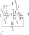
- FIG. 2 is a block diagram of a power transfer system 100 including modular solid-state power conversion and fault protection according to an exemplary embodiment.
- the exemplary embodiment shown in FIG. 2 differs from that in FIG. 1 only on the low side 120.
- the low side sub-modules 130 L are connected in series to the unit 150.
- the unit 150 may be a load, a battery, or a DC source according to alternate embodiments. Based on the series connection, voltage across each low side sub-module 130 L is scaled down in proportion to the number of low side sub-modules 130 L .
- FIG. 3 details an exemplary sub-module 130 according to one or more embodiments.
- the presence or order of the components discussed with reference to FIG. 3 may be altered according to different embodiments.
- the high side sub-module 130 H and the low side sub-module 130 L of a module 131 need not be assembled in the same way.
- the order shown in FIG. 3 may be reversed within a sub-module 130 on the low side 120.
- Converters 310 and 330 are separated by an energy storage device 320.
- the energy storage device 320 is a DC capacitor 325.
- the converters 310 and 330 may each be configured as a full bridge converter, half bridge converter, or T-type three level converter, for example.
- the DC capacitor 325 may be a single or center-tapped DC bus capacitor according to alternate embodiments.
- the role of the DC capacitor 325 or other embodiment of the energy storage device 320 in fault mitigation is further discussed with reference to FIGS. 5A and 5B .
- each sub-module 130 represents a modular solid-state power converter and fault protector according to one or more embodiments.
- An impedance network 340 may be included to enhance power transfer and improve the harmonics of the converters 310, 330 and may be implemented according to a number of alternate embodiments.
- the impedance network 340 may be a z-impedance network, a parallel inductor-capacitor (LC) network, a series LC network, or a string of LC networks.
- the impedance network 340 may be a capacitor-inductor-capacitor (CLC) network, a CLC network with coupled inductors, or an inductor-capacitor-inductor (LCL) network.
- the inductor 135 may additionally serve the function of the impedance network 340.
- the presence and function of the converts 310, 330 may be based on whether the sub-module 130 is a high side sub-module 130 H or a low side sub-module 130 L and on the direction of power transfer.
- the converter 310 of the high side sub-module 130 H is a DC-to-DC converter to convert the MVDC or HVDC to LVDC.
- the converter 330 of the high side sub-module 130 H is an inverter that transforms the LVDC to alternating current (AC) to facilitate the inductive coupling.
- the converter 330 of the low side sub-module 130 L functions as a rectifier that outputs the LVDC on the low side 120, and the converter 310 is not needed in the low side sub-module 130 L .
- the low side sub-module 130 L may include a converter 330 that performs DC-to-DC conversion and a converter 310 that functions as an inverter to produce AC that facilitates inductive coupling (i.e., coupling of magnetic flux).
- FIG. 4 details an exemplary sub-module 130 according to one or more embodiments.
- the sub-module 130 shown in FIG. 4 may be a high side sub-module 130 H for explanatory purposes.
- a battery 410 is used as the energy storage device 320 in the exemplary high side sub-module 130 H .
- a set of batteries 410 acting as the energy storage devices 320 in the set of high side sub-modules 130 H may replace a high voltage battery connected directly or via another DC-to-DC converter at the high side.
- the set of batteries 410 is easier to design and is safer and more reliable than a single high voltage battery.
- multiple battery chemistries of different ages may be mixed via the set of batteries 410 and managed in their individual high side sub-modules 130 H .
- the energy storage device 320 may have other implementations.
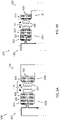
- FIGS. 5A and 5B show aspects of an exemplary power transfer system 100 to illustrate fault handling according to an exemplary embodiment.
- One module 131 with a high side sub-module 130 H and a low side sub-module 130L is shown.
- the exemplary high side sub-module 130 H includes converts 310 and 330 implemented as full bridge converters, a DC capacitor 325 implemented as a single DC bus capacitor, and a mutually coupled inductor 135 that also serves as the impedance network 440.
- the low side sub-module 130 L includes an inductor 135 (functioning as the impedance network 440, as well), a converter 330 serving as a rectifier and implemented as a full bridge converter, and a DC capacitor 325.
- FIG. 5A shows a path of the load current i on the high side 110 during normal operation.
- the DC capacitor 325 of the high side sub-module 130 H transfers power to the low side 120 using the full bridge inverter (converter 330). Based on the amount of power transfer, the voltage of the DC capacitor 325 decreases over time and must be charged back to a nominal voltage.
- FIG. 5B shows a path of the load current i on the high side 110 during recharge of the DC capacitor 325 of the high side sub-module 130 H or during a fault condition.
- FIG. 5A it may be determined that the DC capacitor 325 of the high side sub-module 130 H must be charged. Alternately, a fault may be detected. Fault detection is performed according to known and previously used techniques and is not detailed herein.
- the flow path of the load current i is switched to include the DC capacitor 325 of the high side sub-module 130 H .
- the path shown in FIG. 5B is taken momentarily.
- the path shown in FIG. 5B is maintained until the fault is fully cleared.
- the DC capacitor 325 in the high side sub-module 130 H is used to absorb the fault current and disrupt power transfer to the low side 120 during the fault condition. Because this capability is in each high side sub-module 130 H , modular fault protection, rather than a single break in the circuit, is facilitated.
Landscapes
- Engineering & Computer Science (AREA)
- Power Engineering (AREA)
- Dc-Dc Converters (AREA)
Abstract
Description
- Exemplary embodiments pertain to the art of electrical power distribution and, in particular, to a modular solid-state power converter and fault protector.
- Electrical power distribution presents a challenge in applications with an increasing demand for power and with loads that require different levels of power. Electric aircraft and aerospace applications, for example, may require a high voltage direct current (HVDC) system (e.g., on the order of 3 kilovolts (kV) for propulsion). DC-to-DC conversion may be performed in stages to provide power to high voltage systems like the wing ice protection system (e.g., on the order of 800 V) and, ultimately, devices that require low voltage DC (LVDC) (e.g., on the order of 28 V).
- In one embodiment, an electrical power distribution system includes a first high side sub-module including a high side converter and a high side energy storage device. The first high side sub-module is electrically coupled to a high side load that requires a high voltage or medium voltage DC, the high voltage DC being higher than the medium voltage DC. The system also includes a first low side sub-module including a low side converter and a low side energy storage device. The first high side sub-module and the first low side sub-module are configured to be inductively coupled. The first high side sub-module and the first low side sub-module form a first module.
- In embodiments, the first low side sub-module may be electrically coupled to a low side load that requires a low voltage DC, the low voltage DC being lower than the medium voltage DC or to a low side battery.
- In this or other embodiments, the first low side sub-module may be connected to a DC source and the first low side sub-module may be configured to transfer power to the first high side sub-module.
- In this or other embodiments, the system may also include a second module including a second high side sub-module and a second low side sub-module that are inductively coupled.
- In this or other embodiments, the first high side sub-module and the second high side sub-module may be connected in series to the high side load.
- The first low side sub-module and the second low side sub-module may be connected in series to a load, a battery, or a DC source.
- In embodiments, the first low side sub-module and the second low side sub-module may be connected in parallel to a load, a battery, or a DC source.
- In embodiments, the high side energy storage device or the low side energy storage device may be a direct current (DC) capacitor or a battery.
- In embodiments, the high side DC capacitor in the first high side sub-module may be arranged to build up charge based on a fault current detection and to be outside a path of current flow based on a lack of the fault current detection.
- In embodiments, the first high side sub-module may include a second high side converter configured to function as an inverter based on the high side converter being configure to function as a DC-to-DC converter and the low side converter being configured to function as a rectifier.
- In another aspect, a method of assembling an electrical power distribution system includes assembling a first high side sub-module to include a high side converter and a high side energy storage device and electrically coupling the first high side sub-module to a high side load that requires a high voltage or medium voltage DC. The high voltage DC being higher than the medium voltage DC. The method also includes assembling a first low side sub-module to include a low side converter and a low side energy storage device and arranging the first high side sub-module and the first low side sub-module to be inductively coupled. The first high side sub-module and the first low side sub-module form a first module.
- In embodiments, the method may also include electrically coupling the first low side sub-module to a low side load that requires a low voltage DC, the low voltage DC being lower than the medium voltage DC, or connecting the first low side sub-module to a low side battery.
- In other embodiments, the method may also include connecting the first low side sub-module to a DC source for power transfer from the first low side sub-module to the first high side sub-module.
- The method may also include assembling a second module to include a second high side sub-module and a second low side sub-module that are inductively coupled.
- The method may also include connecting the first high side sub-module and the second high side sub-module to the high side load in series.
- The method may also include connecting the first low side sub-module and the second low side sub-module to a load, a battery, or a DC source in series.
- The method may also include connecting the first low side sub-module and the second low side sub-module to a load, a battery, or a DC source in parallel.
- The high side energy storage device or the low side energy storage device may be a direct current (DC) capacitor or a battery.
- The method may also include arranging the high side DC capacitor in the first high side sub-module to build up charge based on a fault current detection and to be outside a path of current flow based on a lack of the fault current detection.
- Assembling the first high side sub-module may include arranging a second high side converter to function as an inverter based on the high side converter being configured to function as a DC-to-DC converter and the low side converter being configured to function as a rectifier.
- The following descriptions should not be considered limiting in any way. With reference to the accompanying drawings, like elements are numbered alike:
-
FIG. 1 is a block diagram of a power transfer system including modular solid-state power conversion and fault protection according to an exemplary embodiment; -
FIG. 2 is a block diagram of a power transfer system including modular solid-state power conversion and fault protection according to an exemplary embodiment; -
FIG. 3 details an exemplary sub-module according to one or more embodiments; and -
FIG. 4 details an exemplary sub-module according to one or more embodiments; -
FIG. 5A illustrates current flow through a high side sub-module during normal operation; and -
FIG. 5B illustrates current flow through the high side sub-module during a fault condition. - A detailed description of one or more embodiments of the disclosed apparatus and method are presented herein by way of exemplification and not limitation with reference to the Figures.
- As previously noted, providing the appropriate voltage needed by the various devices of a system (e.g., an aircraft) may involve DC-to-DC conversion. Additionally, a circuit breaker may be used to break a fault current. A prior approach involves a LVDC bus and a HVDC bus connected in one or more power conversion stages. A circuit breaker arranged prior to a converter breaks a fault current. That is, one circuit breaker is arranged between the source and load to break the fault current.
- Embodiments of the systems and methods detailed herein relate to a modular solid-state power converter and fault protector. The functions of converting power and addressing fault current are integrated in a number of modules with each module for conversion and fault protection being made up of a sub-module on the high or medium voltage DC (HVDC/MVDC) side and a sub-module on the LVDC side. Sub-modules on the HVDC/MVDC side of each module are electrically coupled to a load in series while sub-modules on the LVDC side are electrically coupled to a source, load, or battery in parallel or in series. HVDC (e.g., 3 kV), MVDC (e.g., 800 V), LVDC (e.g., 28V) are not limited by a particular range of voltages but may be defined relative to each other. As previously noted, each module is made up of a sub-module on the HVDC/MVDC side and a sub-module on the LVDC side. The sub-modules of a module are magnetically coupled to facilitate power transfer from the high side to the low side or from the low side to the high side over an air gap while providing galvanic isolation between the two sides. As detailed, fault current may be limited or controlled rather than only being broken based on the fault protection integrated into each sub-module.
-
FIG. 1 is a block diagram of apower transfer system 100 including modular solid-state power conversion and fault protection according to an exemplary embodiment. Thepower transfer system 100 includes a high side 110 (MVDC or HVDC) and a low side 120 (LVDC). Thepower transfer system 100 is indicated as including a number of modules 131-1 through 131-n (generally referred to as 131). Two of the modules 131-1 and 131-n are shown for explanatory purposes. Module 131-1 includes a high side sub-module 130Ha (indicated as SMH1) and a low side sub-module 130La (indicated as SML1), and module 131-n includes ahigh side sub-module 130c (indicated as SMHn) and alow side sub-module 130d (indicated as SMLn), each referred to generally ashigh side sub-module 130H andlow side sub-module 130L orsub-module 130.High side sub-module 130Ha andlow side sub-module 130La respectively includeinductors high side sub-module 130Hn andlow side sub-module 130Ln respectively includeinductors inductors 135. - Thus, the exemplary
power transfer system 100 includes any number ofmodules 131, and eachmodule 131 includes ahigh side sub-module 130H and alow side sub-module 130L that are magnetically coupled by theirrespective inductors 135, as indicated by mutual inductance value M. The magnetic coupling provides galvanic isolation between thehigh side 110 and thelow side 120 while transferring power from thehigh side 110 to thelow side 120 or from thelow side 120 to thehigh side 110 over anair gap 137. - As shown in
FIG. 1 , on thehigh side 110, the high side sub-modules 130H are connected in series between an inputDC power source 105 and ahigh side load 140. Based on the series connection, the voltage and power rating of the high side sub-modules 130H scales down in proportion to the number ofhigh side sub-modules 130H. On thelow side 120, thelow side sub-modules 130L are connected in parallel to aunit 150. According to an exemplary embodiment, theunit 150 is a load. According to an alternate embodiment, theunit 150 is a battery. According to yet another exemplary embodiment, theunit 150 is a DC source such that power transfer is from thelow side 120 to thehigh side 110. Based on the parallel connection, the current and power rating of thelow side sub-modules 130L scales down in proportion to the number oflow side sub-modules 130L. -
FIG. 2 is a block diagram of apower transfer system 100 including modular solid-state power conversion and fault protection according to an exemplary embodiment. The exemplary embodiment shown inFIG. 2 differs from that inFIG. 1 only on thelow side 120. Specifically, thelow side sub-modules 130L are connected in series to theunit 150. As previously noted, theunit 150 may be a load, a battery, or a DC source according to alternate embodiments. Based on the series connection, voltage across eachlow side sub-module 130L is scaled down in proportion to the number oflow side sub-modules 130L. -
FIG. 3 details an exemplary sub-module 130 according to one or more embodiments. The presence or order of the components discussed with reference toFIG. 3 may be altered according to different embodiments. Further, the high side sub-module 130H and thelow side sub-module 130L of amodule 131 need not be assembled in the same way. For example, the order shown inFIG. 3 may be reversed within a sub-module 130 on thelow side 120.Converters energy storage device 320. In the exemplary embodiment shown inFIG. 3 , theenergy storage device 320 is aDC capacitor 325. Theconverters DC capacitor 325 may be a single or center-tapped DC bus capacitor according to alternate embodiments. The role of theDC capacitor 325 or other embodiment of theenergy storage device 320 in fault mitigation is further discussed with reference toFIGS. 5A and 5B . Based on one or both of theconverters - An
impedance network 340 may be included to enhance power transfer and improve the harmonics of theconverters impedance network 340 may be a z-impedance network, a parallel inductor-capacitor (LC) network, a series LC network, or a string of LC networks. According to additional alternates, theimpedance network 340 may be a capacitor-inductor-capacitor (CLC) network, a CLC network with coupled inductors, or an inductor-capacitor-inductor (LCL) network. According to yet another embodiment, as shown inFIGS. 5A and 5B , for example, theinductor 135 may additionally serve the function of theimpedance network 340. - The presence and function of the
converts low side sub-module 130L and on the direction of power transfer. When power transfer is from the high side sub-module 130H to thelow side sub-module 130L, theconverter 310 of the high side sub-module 130H is a DC-to-DC converter to convert the MVDC or HVDC to LVDC. Theconverter 330 of the high side sub-module 130H is an inverter that transforms the LVDC to alternating current (AC) to facilitate the inductive coupling. In this case, theconverter 330 of the low side sub-module 130L functions as a rectifier that outputs the LVDC on thelow side 120, and theconverter 310 is not needed in thelow side sub-module 130L. This is the exemplary arrangement shown inFIGS. 5A and 5B . As another example, when power transfer is from the low side sub-module 130L to the high side sub-module130H, the low side sub-module 130L may include aconverter 330 that performs DC-to-DC conversion and aconverter 310 that functions as an inverter to produce AC that facilitates inductive coupling (i.e., coupling of magnetic flux). -
FIG. 4 details an exemplary sub-module 130 according to one or more embodiments. The sub-module 130 shown inFIG. 4 may be a high side sub-module 130H for explanatory purposes. Abattery 410 is used as theenergy storage device 320 in the exemplaryhigh side sub-module 130H. A set ofbatteries 410 acting as theenergy storage devices 320 in the set of high side sub-modules 130H may replace a high voltage battery connected directly or via another DC-to-DC converter at the high side. The set ofbatteries 410 is easier to design and is safer and more reliable than a single high voltage battery. In addition, multiple battery chemistries of different ages may be mixed via the set ofbatteries 410 and managed in their individualhigh side sub-modules 130H. In further alternate embodiments, theenergy storage device 320 may have other implementations. -
FIGS. 5A and 5B show aspects of an exemplarypower transfer system 100 to illustrate fault handling according to an exemplary embodiment. Onemodule 131 with a high side sub-module 130H and a low side sub-module 130L is shown. The exemplary high side sub-module 130H includesconverts DC capacitor 325 implemented as a single DC bus capacitor, and a mutually coupledinductor 135 that also serves as the impedance network 440. Thelow side sub-module 130L includes an inductor 135 (functioning as the impedance network 440, as well), aconverter 330 serving as a rectifier and implemented as a full bridge converter, and aDC capacitor 325. -
FIG. 5A shows a path of the load current i on thehigh side 110 during normal operation. TheDC capacitor 325 of the high side sub-module 130H transfers power to thelow side 120 using the full bridge inverter (converter 330). Based on the amount of power transfer, the voltage of theDC capacitor 325 decreases over time and must be charged back to a nominal voltage. -
FIG. 5B shows a path of the load current i on thehigh side 110 during recharge of theDC capacitor 325 of the high side sub-module 130H or during a fault condition. During normal operation, shown inFIG. 5A , it may be determined that theDC capacitor 325 of the high side sub-module 130H must be charged. Alternately, a fault may be detected. Fault detection is performed according to known and previously used techniques and is not detailed herein. - In either the case (i.e., to charge the
DC capacitor 325 on thehigh side 110 or based on fault detection), the flow path of the load current i is switched to include theDC capacitor 325 of thehigh side sub-module 130H. When the purpose is to charge theDC capacitor 325 of thehigh side 110, the path shown inFIG. 5B is taken momentarily. When a fault is detected, the path shown inFIG. 5B is maintained until the fault is fully cleared. By switching from the current path shown inFIG. 5A to the one shown inFIG. 5B , theDC capacitor 325 in the high side sub-module 130H is used to absorb the fault current and disrupt power transfer to thelow side 120 during the fault condition. Because this capability is in each high side sub-module 130H, modular fault protection, rather than a single break in the circuit, is facilitated. - The terminology used herein is for the purpose of describing particular embodiments only and is not intended to be limiting of the present disclosure. As used herein, the singular forms "a", "an" and "the" are intended to include the plural forms as well, unless the context clearly indicates otherwise. It will be further understood that the terms "comprises" and/or "comprising," when used in this specification, specify the presence of stated features, integers, steps, operations, elements, and/or components, but do not preclude the presence or addition of one or more other features, integers, steps, operations, element components, and/or groups thereof.
- While the present disclosure has been described with reference to an exemplary embodiment or embodiments, it will be understood by those skilled in the art that various changes may be made without departing from the scope of the invention as defined by the claims. In addition, many modifications may be made to adapt a particular situation or material to the teachings of the present disclosure without departing from the scope of the claims. Therefore, it is intended that the present disclosure not be limited to the particular embodiment disclosed as the best mode contemplated for carrying out this present disclosure, but that the present disclosure will include all embodiments falling within the scope of the claims.
Claims (15)
- An electrical power distribution system comprising:a first high side sub-module (130Ha) including a high side converter (310) and a high side energy storage device (320), wherein the first high side sub-module is electrically coupled to a high side load (140) that requires a high voltage or medium voltage DC, the high voltage DC being higher than the medium voltage DC; anda first low side sub-module (130La) including a low side converter (330) and a low side energy storage device, wherein the first high side sub-module and the first low side sub-module are configured to be inductively coupled and the first high side sub-module and the first low side sub-module form a first module.
- The system according to claim 1, wherein the first low side sub-module is electrically coupled to a low side load that requires a low voltage DC, the low voltage DC being lower than the medium voltage DC or to a low side battery, or wherein the first low side sub-module is connected to a DC source and the first low side sub-module is configured to transfer power to the first high side sub-module.
- The system according to claim 1 or 2, further comprising a second module including a second high side sub-module and a second low side sub-module that are inductively coupled.
- The system according to claim 3, wherein the first high side sub-module and the second high side sub-module are connected in series to the high side load.
- The system according to claim 3, wherein the first low side sub-module and the second low side sub-module are connected in series to a load, a battery, or a DC source, or wherein the first low side sub-module and the second low side sub-module are connected in parallel to a load, a battery, or a DC source.
- The system according to any preceding claim, wherein the high side energy storage device or the low side energy storage device is a direct current, DC, capacitor or a battery.
- The system according to any preceding claim, wherein the high side DC capacitor in the first high side sub-module is arranged to build up charge based on a fault current detection and to be outside a path of current flow based on a lack of the fault current detection.
- The system according to any preceding claim, wherein the first high side sub-module includes a second high side converter configured to function as an inverter based on the high side converter being configure to function as a DC-to-DC converter and the low side converter being configured to function as a rectifier.
- A method of assembling an electrical power distribution system, the method comprising:assembling a first high side sub-module to include a high side converter and a high side energy storage device;electrically coupling the first high side sub-module to a high side load that requires a high voltage or medium voltage DC, the high voltage DC being higher than the medium voltage DC;assembling a first low side sub-module to include a low side converter and a low side energy storage device; andarranging the first high side sub-module and the first low side sub-module to be inductively coupled, wherein the first high side sub-module and the first low side sub-module form a first module.
- The method according to claim 9, further comprising electrically coupling the first low side sub-module to a low side load that requires a low voltage DC, the low voltage DC being lower than the medium voltage DC, or connecting the first low side sub-module to a low side battery, or further comprising connecting the first low side sub-module to a DC source for power transfer from the first low side sub-module to the first high side sub-module.
- The method according to claim 9 or 10, further comprising assembling a second module to include a second high side sub-module and a second low side sub-module that are inductively coupled.
- The method according to claim 11, further comprising connecting the first high side sub-module and the second high side sub-module to the high side load in series.
- The method according to claim 11 or 12, further comprising connecting the first low side sub-module and the second low side sub-module to a load, a battery, or a DC source in series, or further comprising connecting the first low side sub-module and the second low side sub-module to a load, a battery, or a DC source in parallel.
- The method according to any of claims 9 to 13, further comprising arranging the high side DC capacitor in the first high side sub-module to build up charge based on a fault current detection and to be outside a path of current flow based on a lack of the fault current detection.
- The method according to any of claims 9 to 14, wherein the assembling the first high side sub-module includes arranging a second high side converter to function as an inverter based on the high side converter being configure to function as a DC-to-DC converter and the low side converter being configured to function as a rectifier.
Applications Claiming Priority (1)
| Application Number | Priority Date | Filing Date | Title |
|---|---|---|---|
| US17/327,119 US11728738B2 (en) | 2021-05-21 | 2021-05-21 | Modular solid-state power converter and fault protector |
Publications (1)
| Publication Number | Publication Date |
|---|---|
| EP4092898A1 true EP4092898A1 (en) | 2022-11-23 |
Family
ID=81750432
Family Applications (1)
| Application Number | Title | Priority Date | Filing Date |
|---|---|---|---|
| EP22174646.4A Pending EP4092898A1 (en) | 2021-05-21 | 2022-05-20 | Modular solid-state power converter and fault protector |
Country Status (2)
| Country | Link |
|---|---|
| US (1) | US11728738B2 (en) |
| EP (1) | EP4092898A1 (en) |
Families Citing this family (1)
| Publication number | Priority date | Publication date | Assignee | Title |
|---|---|---|---|---|
| GB2640491A (en) * | 2024-02-29 | 2025-10-29 | Airbus Operations Ltd | A sleeve for a pair of wiring harnesses |
Citations (3)
| Publication number | Priority date | Publication date | Assignee | Title |
|---|---|---|---|---|
| US20070195557A1 (en) * | 2006-02-21 | 2007-08-23 | Ut-Battelle Llc | Triple voltage DC-to-DC converter and method |
| EP3696931A1 (en) * | 2019-02-15 | 2020-08-19 | Hamilton Sundstrand Corporation | Dual active bridge energy storage module systems |
| US20210067047A1 (en) * | 2019-02-04 | 2021-03-04 | Ford Global Technologies, Llc | Vehicle power control systems |
Family Cites Families (5)
| Publication number | Priority date | Publication date | Assignee | Title |
|---|---|---|---|---|
| DE102010008978B4 (en) | 2010-02-24 | 2012-10-04 | Rainer Marquardt | Circuit arrangement for modular drive converter |
| WO2015005155A1 (en) * | 2013-07-08 | 2015-01-15 | 株式会社村田製作所 | Power conversion circuit, power transmission system, and power conversion system |
| CA2947465A1 (en) | 2015-11-18 | 2017-05-18 | General Electric Company | A system and method for fault ride through |
| US10454393B2 (en) | 2016-07-25 | 2019-10-22 | The Boeing Company | Balancing current within a parallel modular converter system |
| DE102018201206A1 (en) | 2018-01-26 | 2019-08-01 | Siemens Aktiengesellschaft | Modular arrangement of an inverter and aircraft with such an arrangement |
-
2021
- 2021-05-21 US US17/327,119 patent/US11728738B2/en active Active
-
2022
- 2022-05-20 EP EP22174646.4A patent/EP4092898A1/en active Pending
Patent Citations (3)
| Publication number | Priority date | Publication date | Assignee | Title |
|---|---|---|---|---|
| US20070195557A1 (en) * | 2006-02-21 | 2007-08-23 | Ut-Battelle Llc | Triple voltage DC-to-DC converter and method |
| US20210067047A1 (en) * | 2019-02-04 | 2021-03-04 | Ford Global Technologies, Llc | Vehicle power control systems |
| EP3696931A1 (en) * | 2019-02-15 | 2020-08-19 | Hamilton Sundstrand Corporation | Dual active bridge energy storage module systems |
Also Published As
| Publication number | Publication date |
|---|---|
| US11728738B2 (en) | 2023-08-15 |
| US20220376626A1 (en) | 2022-11-24 |
Similar Documents
| Publication | Publication Date | Title |
|---|---|---|
| CN109428490B (en) | Multi-cell power conversion system | |
| EP3213382B1 (en) | System for handling short circuits on an electrical network | |
| US20080252142A1 (en) | Apparatus for Electrical Power Transmission | |
| EP3985821A1 (en) | Power grid | |
| US20180219479A1 (en) | Bipolar high-voltage network and method for operating a bipolar high-voltage network | |
| CN115362610B (en) | SST system with multiple LVDC outputs | |
| US11967859B2 (en) | Power factor correction circuit, power factor correction assembly and on-line uninterruptible power supply comprising same | |
| EP3411946B1 (en) | Bidirectional dc-dc resonant converter | |
| EP2913905B1 (en) | DC power transmission systems and method of assembling the same | |
| KR20110107817A (en) | Series connection of on-off regulators for energy transmission within the battery system | |
| CN105322607B (en) | For providing voltage, there is the series connection device and drive arrangement of group current transformer | |
| CN103384073A (en) | Battery system, method for charging battery modules, and method for balancing battery modules | |
| US9225255B2 (en) | Power supply system, comprising a converter connected to a network and a transformer connected in parallel relative to the converter to limit the homopolar current, and a drive chain comprising such a power supply system | |
| US10903648B2 (en) | Wind park with multiple wind turbines | |
| KR102467712B1 (en) | Power supply system and method | |
| CN116054577A (en) | Energy systems for electric vehicles | |
| CN109792158A (en) | Hybrid Active Power Link Module Apparatus and Related Systems and Methods | |
| JPH10136552A (en) | Overcurrent protection circuit for non-isolated battery discharge controller | |
| US11728738B2 (en) | Modular solid-state power converter and fault protector | |
| WO2011158051A1 (en) | System and method for charge balancing and/or charging electrical energy-storing units | |
| KR20140117743A (en) | Battery device and energy storage system including the same | |
| US20250007270A1 (en) | Ultra-Efficient And Self-Healing Solid State Circuit Breaker | |
| EP3002864A1 (en) | Power converter and control method | |
| CN111987919B (en) | Power Converters | |
| US11108236B2 (en) | Electrical energy storage module, associated system and method |
Legal Events
| Date | Code | Title | Description |
|---|---|---|---|
| PUAI | Public reference made under article 153(3) epc to a published international application that has entered the european phase |
Free format text: ORIGINAL CODE: 0009012 |
|
| STAA | Information on the status of an ep patent application or granted ep patent |
Free format text: STATUS: THE APPLICATION HAS BEEN PUBLISHED |
|
| AK | Designated contracting states |
Kind code of ref document: A1 Designated state(s): AL AT BE BG CH CY CZ DE DK EE ES FI FR GB GR HR HU IE IS IT LI LT LU LV MC MK MT NL NO PL PT RO RS SE SI SK SM TR |
|
| STAA | Information on the status of an ep patent application or granted ep patent |
Free format text: STATUS: REQUEST FOR EXAMINATION WAS MADE |
|
| 17P | Request for examination filed |
Effective date: 20230523 |
|
| RBV | Designated contracting states (corrected) |
Designated state(s): AL AT BE BG CH CY CZ DE DK EE ES FI FR GB GR HR HU IE IS IT LI LT LU LV MC MK MT NL NO PL PT RO RS SE SI SK SM TR |