EP4092894A1 - Power supply monitoring and switching control - Google Patents
Power supply monitoring and switching control Download PDFInfo
- Publication number
- EP4092894A1 EP4092894A1 EP22173864.4A EP22173864A EP4092894A1 EP 4092894 A1 EP4092894 A1 EP 4092894A1 EP 22173864 A EP22173864 A EP 22173864A EP 4092894 A1 EP4092894 A1 EP 4092894A1
- Authority
- EP
- European Patent Office
- Prior art keywords
- magnitude
- output voltage
- soft start
- switching period
- power supply
- Prior art date
- Legal status (The legal status is an assumption and is not a legal conclusion. Google has not performed a legal analysis and makes no representation as to the accuracy of the status listed.)
- Withdrawn
Links
- 238000012544 monitoring process Methods 0.000 title claims description 5
- 238000000034 method Methods 0.000 claims description 50
- 230000003213 activating effect Effects 0.000 claims description 21
- 230000004044 response Effects 0.000 claims description 9
- 230000004913 activation Effects 0.000 claims description 5
- 238000001514 detection method Methods 0.000 claims description 5
- 238000006243 chemical reaction Methods 0.000 abstract description 4
- 238000004891 communication Methods 0.000 description 24
- 238000010586 diagram Methods 0.000 description 21
- 239000000758 substrate Substances 0.000 description 18
- 230000033228 biological regulation Effects 0.000 description 11
- 238000012545 processing Methods 0.000 description 11
- 239000003990 capacitor Substances 0.000 description 6
- 230000006870 function Effects 0.000 description 5
- 230000007423 decrease Effects 0.000 description 4
- 230000015654 memory Effects 0.000 description 4
- 239000004020 conductor Substances 0.000 description 3
- 230000005669 field effect Effects 0.000 description 3
- 230000008569 process Effects 0.000 description 3
- 230000011664 signaling Effects 0.000 description 3
- 230000007704 transition Effects 0.000 description 3
- 238000004590 computer program Methods 0.000 description 2
- 230000008878 coupling Effects 0.000 description 2
- 238000010168 coupling process Methods 0.000 description 2
- 238000005859 coupling reaction Methods 0.000 description 2
- 230000001419 dependent effect Effects 0.000 description 2
- 230000000694 effects Effects 0.000 description 2
- 238000010295 mobile communication Methods 0.000 description 2
- 230000003287 optical effect Effects 0.000 description 2
- 230000009467 reduction Effects 0.000 description 2
- OKTJSMMVPCPJKN-UHFFFAOYSA-N Carbon Chemical compound [C] OKTJSMMVPCPJKN-UHFFFAOYSA-N 0.000 description 1
- 230000009471 action Effects 0.000 description 1
- 238000013473 artificial intelligence Methods 0.000 description 1
- 230000008901 benefit Effects 0.000 description 1
- 230000005540 biological transmission Effects 0.000 description 1
- 229910052799 carbon Inorganic materials 0.000 description 1
- 230000008859 change Effects 0.000 description 1
- 238000007796 conventional method Methods 0.000 description 1
- 230000003247 decreasing effect Effects 0.000 description 1
- 230000007812 deficiency Effects 0.000 description 1
- 238000005265 energy consumption Methods 0.000 description 1
- 238000005516 engineering process Methods 0.000 description 1
- 239000000463 material Substances 0.000 description 1
- 238000005259 measurement Methods 0.000 description 1
- 230000004048 modification Effects 0.000 description 1
- 238000012986 modification Methods 0.000 description 1
- 230000010355 oscillation Effects 0.000 description 1
- 239000000126 substance Substances 0.000 description 1
- 230000001988 toxicity Effects 0.000 description 1
- 231100000419 toxicity Toxicity 0.000 description 1
Images




Classifications
-
- H—ELECTRICITY
- H02—GENERATION; CONVERSION OR DISTRIBUTION OF ELECTRIC POWER
- H02M—APPARATUS FOR CONVERSION BETWEEN AC AND AC, BETWEEN AC AND DC, OR BETWEEN DC AND DC, AND FOR USE WITH MAINS OR SIMILAR POWER SUPPLY SYSTEMS; CONVERSION OF DC OR AC INPUT POWER INTO SURGE OUTPUT POWER; CONTROL OR REGULATION THEREOF
- H02M1/00—Details of apparatus for conversion
-
- H—ELECTRICITY
- H02—GENERATION; CONVERSION OR DISTRIBUTION OF ELECTRIC POWER
- H02M—APPARATUS FOR CONVERSION BETWEEN AC AND AC, BETWEEN AC AND DC, OR BETWEEN DC AND DC, AND FOR USE WITH MAINS OR SIMILAR POWER SUPPLY SYSTEMS; CONVERSION OF DC OR AC INPUT POWER INTO SURGE OUTPUT POWER; CONTROL OR REGULATION THEREOF
- H02M1/00—Details of apparatus for conversion
- H02M1/0003—Details of control, feedback or regulation circuits
- H02M1/0006—Arrangements for supplying an adequate voltage to the control circuit of converters
-
- H—ELECTRICITY
- H02—GENERATION; CONVERSION OR DISTRIBUTION OF ELECTRIC POWER
- H02M—APPARATUS FOR CONVERSION BETWEEN AC AND AC, BETWEEN AC AND DC, OR BETWEEN DC AND DC, AND FOR USE WITH MAINS OR SIMILAR POWER SUPPLY SYSTEMS; CONVERSION OF DC OR AC INPUT POWER INTO SURGE OUTPUT POWER; CONTROL OR REGULATION THEREOF
- H02M1/00—Details of apparatus for conversion
- H02M1/08—Circuits specially adapted for the generation of control voltages for semiconductor devices incorporated in static converters
-
- H—ELECTRICITY
- H02—GENERATION; CONVERSION OR DISTRIBUTION OF ELECTRIC POWER
- H02M—APPARATUS FOR CONVERSION BETWEEN AC AND AC, BETWEEN AC AND DC, OR BETWEEN DC AND DC, AND FOR USE WITH MAINS OR SIMILAR POWER SUPPLY SYSTEMS; CONVERSION OF DC OR AC INPUT POWER INTO SURGE OUTPUT POWER; CONTROL OR REGULATION THEREOF
- H02M1/00—Details of apparatus for conversion
- H02M1/08—Circuits specially adapted for the generation of control voltages for semiconductor devices incorporated in static converters
- H02M1/088—Circuits specially adapted for the generation of control voltages for semiconductor devices incorporated in static converters for the simultaneous control of series or parallel connected semiconductor devices
-
- H—ELECTRICITY
- H02—GENERATION; CONVERSION OR DISTRIBUTION OF ELECTRIC POWER
- H02M—APPARATUS FOR CONVERSION BETWEEN AC AND AC, BETWEEN AC AND DC, OR BETWEEN DC AND DC, AND FOR USE WITH MAINS OR SIMILAR POWER SUPPLY SYSTEMS; CONVERSION OF DC OR AC INPUT POWER INTO SURGE OUTPUT POWER; CONTROL OR REGULATION THEREOF
- H02M1/00—Details of apparatus for conversion
- H02M1/36—Means for starting or stopping converters
-
- H—ELECTRICITY
- H02—GENERATION; CONVERSION OR DISTRIBUTION OF ELECTRIC POWER
- H02M—APPARATUS FOR CONVERSION BETWEEN AC AND AC, BETWEEN AC AND DC, OR BETWEEN DC AND DC, AND FOR USE WITH MAINS OR SIMILAR POWER SUPPLY SYSTEMS; CONVERSION OF DC OR AC INPUT POWER INTO SURGE OUTPUT POWER; CONTROL OR REGULATION THEREOF
- H02M3/00—Conversion of DC power input into DC power output
- H02M3/02—Conversion of DC power input into DC power output without intermediate conversion into AC
- H02M3/04—Conversion of DC power input into DC power output without intermediate conversion into AC by static converters
- H02M3/10—Conversion of DC power input into DC power output without intermediate conversion into AC by static converters using discharge tubes with control electrode or semiconductor devices with control electrode
- H02M3/145—Conversion of DC power input into DC power output without intermediate conversion into AC by static converters using discharge tubes with control electrode or semiconductor devices with control electrode using devices of a triode or transistor type requiring continuous application of a control signal
- H02M3/155—Conversion of DC power input into DC power output without intermediate conversion into AC by static converters using discharge tubes with control electrode or semiconductor devices with control electrode using devices of a triode or transistor type requiring continuous application of a control signal using semiconductor devices only
- H02M3/156—Conversion of DC power input into DC power output without intermediate conversion into AC by static converters using discharge tubes with control electrode or semiconductor devices with control electrode using devices of a triode or transistor type requiring continuous application of a control signal using semiconductor devices only with automatic control of output voltage or current, e.g. switching regulators
- H02M3/157—Conversion of DC power input into DC power output without intermediate conversion into AC by static converters using discharge tubes with control electrode or semiconductor devices with control electrode using devices of a triode or transistor type requiring continuous application of a control signal using semiconductor devices only with automatic control of output voltage or current, e.g. switching regulators with digital control
-
- H—ELECTRICITY
- H02—GENERATION; CONVERSION OR DISTRIBUTION OF ELECTRIC POWER
- H02M—APPARATUS FOR CONVERSION BETWEEN AC AND AC, BETWEEN AC AND DC, OR BETWEEN DC AND DC, AND FOR USE WITH MAINS OR SIMILAR POWER SUPPLY SYSTEMS; CONVERSION OF DC OR AC INPUT POWER INTO SURGE OUTPUT POWER; CONTROL OR REGULATION THEREOF
- H02M3/00—Conversion of DC power input into DC power output
- H02M3/02—Conversion of DC power input into DC power output without intermediate conversion into AC
- H02M3/04—Conversion of DC power input into DC power output without intermediate conversion into AC by static converters
- H02M3/10—Conversion of DC power input into DC power output without intermediate conversion into AC by static converters using discharge tubes with control electrode or semiconductor devices with control electrode
- H02M3/145—Conversion of DC power input into DC power output without intermediate conversion into AC by static converters using discharge tubes with control electrode or semiconductor devices with control electrode using devices of a triode or transistor type requiring continuous application of a control signal
- H02M3/155—Conversion of DC power input into DC power output without intermediate conversion into AC by static converters using discharge tubes with control electrode or semiconductor devices with control electrode using devices of a triode or transistor type requiring continuous application of a control signal using semiconductor devices only
- H02M3/156—Conversion of DC power input into DC power output without intermediate conversion into AC by static converters using discharge tubes with control electrode or semiconductor devices with control electrode using devices of a triode or transistor type requiring continuous application of a control signal using semiconductor devices only with automatic control of output voltage or current, e.g. switching regulators
- H02M3/158—Conversion of DC power input into DC power output without intermediate conversion into AC by static converters using discharge tubes with control electrode or semiconductor devices with control electrode using devices of a triode or transistor type requiring continuous application of a control signal using semiconductor devices only with automatic control of output voltage or current, e.g. switching regulators including plural semiconductor devices as final control devices for a single load
-
- H—ELECTRICITY
- H02—GENERATION; CONVERSION OR DISTRIBUTION OF ELECTRIC POWER
- H02M—APPARATUS FOR CONVERSION BETWEEN AC AND AC, BETWEEN AC AND DC, OR BETWEEN DC AND DC, AND FOR USE WITH MAINS OR SIMILAR POWER SUPPLY SYSTEMS; CONVERSION OF DC OR AC INPUT POWER INTO SURGE OUTPUT POWER; CONTROL OR REGULATION THEREOF
- H02M1/00—Details of apparatus for conversion
- H02M1/0003—Details of control, feedback or regulation circuits
- H02M1/0025—Arrangements for modifying reference values, feedback values or error values in the control loop of a converter
-
- Y—GENERAL TAGGING OF NEW TECHNOLOGICAL DEVELOPMENTS; GENERAL TAGGING OF CROSS-SECTIONAL TECHNOLOGIES SPANNING OVER SEVERAL SECTIONS OF THE IPC; TECHNICAL SUBJECTS COVERED BY FORMER USPC CROSS-REFERENCE ART COLLECTIONS [XRACs] AND DIGESTS
- Y02—TECHNOLOGIES OR APPLICATIONS FOR MITIGATION OR ADAPTATION AGAINST CLIMATE CHANGE
- Y02B—CLIMATE CHANGE MITIGATION TECHNOLOGIES RELATED TO BUILDINGS, e.g. HOUSING, HOUSE APPLIANCES OR RELATED END-USER APPLICATIONS
- Y02B70/00—Technologies for an efficient end-user side electric power management and consumption
- Y02B70/10—Technologies improving the efficiency by using switched-mode power supplies [SMPS], i.e. efficient power electronics conversion e.g. power factor correction or reduction of losses in power supplies or efficient standby modes
Definitions
- One type of conventional power converter is a voltage regulator.
- a controller in the voltage regulator compares the magnitude of a generated output voltage to a setpoint reference voltage. Based on a respective error voltage derived from the comparison, the controller modifies a respective switching frequency and/or pulse width modulation associated with activating high side switch circuitry and low side switch circuitry in the voltage regulator.
- Conventional power converters can be configured to receive a voltage value (such as a so-called VID value) indicating a desired output voltage setting.
- the VID voltage value may vary over time depending on system operation.
- the conventional voltage regulator uses the VID value as the setpoint reference voltage. Accordingly, a device generating the VID value is able to control a magnitude of the output voltage.
- a conventional voltage regulator includes so-called soft start capability.
- soft start capability includes controlling a rate of ramping a voltage applied to a respective load, preventing damage to it.
- clean energy or green technology
- clean energy includes any evolving methods and materials to reduce an overall toxicity on the environment from energy consumption.
- raw energy such as received from green energy sources or non-green energy sources
- an appropriate form such as desired AC voltage, DC voltage, etc.
- energy is stored in a respective one or more battery resource.
- energy is received from a voltage generator or voltage source.
- a power converter is programmed to implement a minimum fixed ON-time value of respective high side switch circuitry.
- the fixed ON-time value may be implemented during a standard operational mode as well as during implementation of a soft start mode. If a fixed frequency controller implements a programmed minimum ON-time value without skipping PWM pulses during soft start, a plateau voltage effect typically exists on the voltage ramp where a magnitude of the voltage at the plateau is the equivalent of the minimum duty cycle times voltage input.
- the magnitude of the output voltage generally cannot be controlled to a desired value for lower magnitudes of the output voltage near (where the plateau exists).
- this issue is more prominently seen as the minimum ON time is enforced for much longer.
- This so-called voltage plateau effect prevents regulation of the output voltage at lower voltage levels, resulting in limited power converter performance.
- Embodiments herein include novel ways of controlling a switching period during implementation of a minimum ON-time value to produce an output voltage via a power supply.
- embodiments herein include an apparatus such as a power supply including a soft start manager.
- the soft start manager controls generation of an output voltage.
- the soft start manager receives input (such as one or more parameters of information) from the power supply; the input (such as an input parameter) is associated with generation of an output voltage that powers a load.
- the soft start manager monitors a magnitude of the input associated with one or more parameters. Based at least in part on the magnitude of the input, the soft start manager controls a switching period applied to switch circuitry in the power supply.
- the input can be any suitable one or more parameters associated with the power supply.
- the input parameter monitored by the soft start manager is a magnitude of the output voltage.
- the input parameter is a duty cycle of activating the switch circuitry in the power supply.
- the duty cycle represents a ratio value of an input voltage and the output voltage; the power supply converts the input voltage into the output voltage.
- the switch circuitry of the power supply as discussed herein is high side switch circuitry.
- the power supply is programmed to implement a minimum pulse width of activating the high side switch circuitry during soft start of the output voltage. Control of the switching period during soft start provides better regulation of the output voltage.
- the power supply includes or implements a PID (Proportional-Integral-Derivative) controller to convert an input voltage into the output voltage; the soft start manager modifies settings of the PID controller of the power supply based on the monitored parameters (such as magnitude of the output voltage, duty cycle, input voltage, etc.).
- PID Proportional-Integral-Derivative
- Further embodiments herein include, via the soft start manager, controlling activation of the switch circuitry and generation of the output voltage during soft start of ramping the output voltage up or down to a target voltage.
- Still further example embodiments herein include, via the soft start manager, varying a magnitude of the switching period applied to the switch circuitry in the power supply depending on the magnitude of the output voltage.
- the soft start manager controls ramping of the magnitude of the switching period over time; the ramping of the switching period results in ramping of the magnitude of the output voltage.
- the ramping of the magnitude of the switching period over time substantially aligns or coincides with ramping of a magnitude of the output voltage. In other words, a magnitude of the output voltage ramps as a magnitude of the switching period is ramped over time.
- a magnitude of the switching period is inversely related to the magnitude of the output voltage. For example, the switching period is larger for lower output voltage magnitudes. Note that the operations as discussed herein can be implemented in any type of controller such as current mode controller, voltage mode controller, etc.
- Yet further embodiments herein include, via the soft start manager, monitor an input voltage used by the power supply to produce the output voltage; and control the switching period applied to the switch circuitry in the power supply based on the magnitude of the input voltage and/or the magnitude of the output voltage.
- the soft start manager implements hysteresis during control of the switching period.
- the soft start manager repeatedly communicates switching period control information to the power supply.
- the soft start manager receives feedback from the power supply; the feedback indicates a status of executing the switching period control information by the power supply.
- each of the received interrupt requests causes the soft start manager to execute instructions to control/adjust the switching period applied to the switch circuitry in the power supply.
- any of the resources as discussed herein can include one or more computerized devices, mobile communication devices, servers, base stations, wireless communication equipment, communication management systems, workstations, user equipment, handheld or laptop computers, or the like to carry out and/or support any or all of the method operations disclosed herein.
- one or more computerized devices or processors can be programmed and/or configured to operate as explained herein to carry out the different embodiments as described herein.
- One such embodiment comprises a computer program product including a non-transitory computer-readable storage medium (i.e., any computer readable hardware storage medium) on which software instructions are encoded for subsequent execution.
- the instructions when executed in a computerized device (hardware) having a processor, program and/or cause the processor (hardware) to perform the operations disclosed herein.
- Such arrangements are typically provided as software, code, instructions, and/or other data (e.g., data structures) arranged or encoded on a non-transitory computer readable storage medium such as an optical medium (e.g., CD-ROM), floppy disk, hard disk, memory stick, memory device, etc., or other a medium such as firmware in one or more ROM, RAM, PROM, etc., or as an Application Specific Integrated Circuit (ASIC), etc.
- the software or firmware or other such configurations can be installed onto a computerized device to cause the computerized device to perform the techniques explained herein.
- embodiments herein are directed to methods, systems, computer program products, etc., that support operations as discussed herein.
- One embodiment herein includes a computer readable storage medium and/or system having instructions stored thereon.
- the instructions when executed by computer processor hardware, cause the computer processor hardware (such as one or more co-located or disparately located processor devices) to: during soft start: receive an input parameter from a power supply, the input parameter associated with generation of an output voltage that powers a load; monitor a magnitude of the input parameter; and based at least in part on the magnitude of the input parameter, control a switching period applied to switch circuitry in the power supply.
- the computer processor hardware such as one or more co-located or disparately located processor devices
- system, method, apparatus, instructions on computer readable storage media, etc., as discussed herein also can be embodied strictly as a software program, firmware, as a hybrid of software, hardware and/or firmware, or as hardware alone such as within a processor (hardware or software), or within an operating system or a within a software application.
- embodiments herein include an apparatus to control a period of operating switches in a power supply to generate an output voltage.
- the apparatus includes a power converter and a soft start manager such as implemented via hardware, software, or a combination of hardware and software.
- High side switch circuitry in the power converter requires activation equal to or greater than a minimal ON-time value.
- Operation of the soft start manager provides improved regulation of the power converter, especially at lower voltage magnitudes.
- the soft start manager receives input (one or more parameters such as output voltage, duty cycle, input voltage, etc.) associated with a power converter.
- the input is an input parameter.
- the power converter converts the input voltage into an output voltage that powers a load.
- the soft start manager monitors a magnitude of the received input (such as one or more parameters, namely, output voltage, duty cycle, input voltage, etc.). Based at least in part on the magnitude of the monitored one or more input parameters, the soft start manager controls a switching period applied to switch circuitry in the power supply. Control of the switching period provides improved power conversion.
- FIG. 1 is an example general diagram of a power supply and corresponding soft start manager according to embodiments herein.
- the power system 100 includes soft start manager 141, power supply 135, and dynamic load 118.
- Power supply 135 includes controller 140 and power converter 165.
- Power converter 165 includes one or more switches 125 controlled by the controller 140 via control signals 105.
- the power converter 165 converts the input voltage 121 (such as any suitable DC input voltage) into the output voltage 123 (such as any suitable DCC output voltage).
- the output voltage 123 (Vout) and corresponding generated output current (i.e., I LOAD ) supply power to the load 118.
- the soft start manager 141 receives one or more signals such as feedback signals (input 102 such as one or more input parameters) associated with the power converter 165.
- the soft start manager 141 receives input 102 such as one or more parameters (output voltage, duty cycle, input voltage, etc.) associated with the power supply 135.
- the soft start manager 141 controls generation of the output voltage 123 based on current operational conditions of the power supply 135. For example, the soft start manager 141 receives input 102 (such as feedback) from the power supply 135. The soft start manager 141 monitors a magnitude of the input 102 (one or more parameters associated with power supply 135).
- the soft start manager 141 controls one or more parameters such as including a switching period (such as captured by controller information 104) applied to one or more switches 125 in the power supply 135, providing improved regulation of generating the output voltage 123.
- the controller 140 is configured to receive a control value TON-MIN, indicating a minimum ON-time value in which to control respective high side switch circuitry in the power supply 135. Implementation of the control TON-MIN ensures proper operation of the power supply 135 and prevents damage to the power supply 135.
- the power supply 135 operates at any suitable switching frequency between 50KHz and 2MHz or other any other suitable switching frequency ranges.
- embodiments herein include, via the soft start manager 141, creating a monotonic soft start ramp of the output voltage 123 and enforcing minimum PWM pulse widths (as indicated by the ON-time value TON-MIN) by modulating the switching period of controlling switches 125 in the power supply 135. Modulation of the switching period during soft start provides accurate generation of the output voltage 123, even at low voltage magnitudes, where a longer switching period allows the small duty cycle to be more easily generated and the low current ripple is more easily tolerated.
- the soft start manager 141 implements a switching period that is greater than the switching period implemented during nominal operation (such as a non-soft start mode when the voltage is above a threshold level and soft start ramping is not needed). In other words, as discussed herein, the soft start manager 141 implements the longer switching periods during soft start ramping of the output voltage 123.
- FIG. 2 is an example diagram illustrating operation of a power converter and generation of an output voltage according to embodiments herein.
- the power converter 165 and corresponding power supply 135 can be configured as any suitable type of power converter or power converter system.
- the power converter phase 165-1 is configured as a buck converter.
- Power converter phase 165-1 includes voltage source 220 (providing input voltage 121), switch Q1 (high side switch circuitry 125-1), switch Q2 (low side switch circuitry 125-2), inductor 144-1, and output capacitor 136 (such as one or more capacitors).
- Switches 125 can be implemented in any suitable manner.
- each of the switches 125 is a so-called field effect transistor. Any suitable type of switches 125 can be used to provide switching as discussed herein.
- the power supply 100 includes any number of power converters 165 (voltage regulators such as power converter 165-1, power converter 165-2, etc.) disposed in parallel to produce the output voltage 123.
- Each voltage converter such as power converter 165-2 operates in a similar manner as power converter 165-1.
- the power converters 165 can be operated in or out of phase with respect to each other.
- the power converter 165-1 in FIG. 2 is shown as a buck converter configuration, note again that the power converter 165 can be instantiated as any suitable type of voltage converter and include any number of phases, providing regulation of a respective output voltage 123 as described herein.
- the switch Q1 of power converter 165-1 is connected in series with switch Q2 between the input voltage source 220 and corresponding ground reference.
- the drain node (D) of the switch Q1 is connected to the voltage source 220 to receive input voltage 121.
- the switch controller 140 drives the gate node (G) of switch Q1 with control signal 105-1.
- the source node (S) of the switch Q1 is connected to the drain node (D) of the switch Q2 at node 296.
- the switch controller 140 drives the gate node (G) of switch Q2 with control signal 105-2.
- the source node (S) of the switch Q2 is connected to ground.
- the power converter 165-1 further includes inductor 144-1.
- Inductor 144-1 extends from the node 296 to the output capacitor 136 and dynamic load 118.
- the node 296 coupling the source (S) node of switch Q1 and the drain (D) node of switch Q2 provides output current through the inductor 144, resulting in generation of the output voltage 123 and corresponding output current I LOAD powering the load 118 and energizing capacitors 136.
- the magnitude of the current I LOAD is equal to a magnitude of the output current through inductor 144-1.
- Output capacitor 136 reduces a ripple voltage associated with the output voltage 123.
- the controller 140 controls switching of the switches Q1 and Q2 based on one or more feedback parameters.
- the controller 140 can be configured to receive output voltage feedback signal 123-1 derived from the output voltage 123 supplied to power the load 118 as previously discussed in FIG. 1 .
- the output voltage feedback signal 123-1 can be the output voltage 123 itself or a proportional derivative voltage value thereof using a resistor divider.
- the controller 140 compares the output voltage feedback signal 123-1 (such as output voltage 123 itself or derivative, or proportional signal) to the reference voltage setpoint 235.
- the reference voltage setpoint 235 is a desired setpoint in which to control a magnitude of the output voltage 123 during load-line regulation implemented by the power supply 135.
- the voltage manager 118-M in or associated with the dynamic load 118 provides control information or feedback (such as a VID value) indicating a desired reference voltage setpoint 235.
- control information or feedback such as a VID value
- the voltage manager 118-M can be configured to provide feedback to the controller 140 indicating a magnitude in which to produce the output voltage 123.
- the feedback such as VID value is used to produce the reference voltage setpoint 235.
- the amplifier or comparator 250 produces a respective error voltage 255 based on a difference between the output voltage feedback signal 123-1 and the reference voltage 235.
- a magnitude of the error voltage 255 generated by the amplifier or comparator 250 varies depending upon the degree to which the magnitude of the output voltage 123 is in or out of regulation (with respect to the reference voltage setpoint 235).
- the controller 140 includes PID controller 258 (control function).
- the PID controller 258 includes a P-component (Proportional component), I-component (Integral component), and a D-component (Derivative component) as known in the art to control operation of switches 125 (Q1 and Q2).
- the output of the PID can proportionally control the duty cycle or ON-time of the PWM, and the PWM pulses may be generated at a fixed or variable switching period or frequency.
- the output of the PID sets the target average current or peak current in the inductor 144-1, and the PWM pulse is dependent on the current sense information, such that the duty cycle or ON time of the PWM is generated based on the PID output and the current sense, with the PWM pulses being generated at fixed or variable switching period or frequency.
- control information 104 includes PID settings (so-called tuning parameters such as gain value Kp applied to the P-component stage, a gain value Ki applied to the I-component stage, and a gain value Kd applied to the D-component stage) produced by the soft start manager 141.
- PID settings (gain value Kp, gain value Ki, gain value Kd) vary depending on the monitored input 102 and conditions associated with producing the output voltage 123.
- the PWM (Pulse Width Modulation) generator 260 of the controller 140 controls operation of switching the switches Q1 and Q2 based upon the magnitude of the signal 256 (such as control output) from the PID controller 258.
- the PWM generator 260 increases a duty cycle or frequency of activating the high side switch Q1 (thus decreasing a duty cycle of activating the low-side switch Q2) in a respective switch control cycle.
- the PWM generator 260 decreases a duty cycle or frequency of activating the high side switch circuitry Q1 (thus increasing a duty cycle of activating the low-side switch Q2) in a respective switching control cycle.
- the controller 140 controls each of the switches Q1 and Q2 ON and OFF at different times to prevent short-circuiting of the input voltage 121 to the ground reference voltage. For example, for a first portion of the control cycle, when the switch Q1 is activated to an ON state, the switch Q2 is deactivated to an OFF state. Conversely, when the switch Q1 is deactivated to an OFF state, the switch Q2 is activated to an ON state.
- controller 140 (via PWM generator 260) implements a dead time (both switches Q1 and Q2 OFF) between state ON-OFF and OFF-ON state transitions to prevent shorting of the input voltage 121 to the ground reference.
- the controller 140 controls generation of the output voltage 123 such that the output voltage 123 remains within a desired voltage range with respect to the reference voltage setpoint 235.
- the magnitude of current 122 through the inductor 144-1 increases when the high-side switch Q1 (such as one or more field effect transistor or other suitable component) is ON and low-side switch Q2 (such as one or more field effect transistor or other suitable component) is OFF; the magnitude of current 122 through the inductor 144-1 decreases when the high-side switch Q1 is OFF and Q2 is ON.
- the high-side switch Q1 such as one or more field effect transistor or other suitable component
- low-side switch Q2 such as one or more field effect transistor or other suitable component
- control information 104 received from the soft start manager 141 includes data indicating a switching period of producing the respective control signals 105.
- the soft start manager 141 monitors the input 102 such as one or more of the magnitude of the output voltage 123, magnitude of the input voltage 121, duty cycle of operating switches 125, etc.
- control of the switching period (or switching frequency) of generating control signals 105 can be achieved in any of multiple different ways.
- FIG. 3 is an example diagram illustrating control of a switching period according to embodiments herein.
- the processor 355 (hardware) implements control function 348 and the soft start manager 141.
- an entity 108 such as an enable pin associated with the processor 355 receives signal 301, causing startup of the control function 348.
- the control function 348 In response to receiving the input 301, the control function 348 generates a respective interrupt request 302.
- the interrupt request causes execution of the soft start manager 141 to change a magnitude of the output voltage 123 to a desired value. This may include ramping a magnitude of the output voltage 123.
- the soft start manager 141 monitors the one or more input parameters such as output voltage 123, input voltage 121, duty cycle, etc., associated with generating the output voltage 123. Based on the one or more monitored parameters, the soft start manager generates control information 104-1 such as settings (such as one or more of switching period settings, PID settings, etc.) to be applied to the controller 140.
- control information 104-1 such as settings (such as one or more of switching period settings, PID settings, etc.) to be applied to the controller 140.
- the soft start manager 141 Via communications 104-1 and corresponding control information from the soft start manager 141 to the controller 140, the soft start manager 141 notifies the controller 140 of an initial switching period value to be applied to the control signals 105.
- the initial setting (magnitude) of the switching period depends on a magnitude (or current bias) of the output voltage 123. Note that the output voltage 123 may start at any suitable magnitude or voltage value.
- the controller 141 acknowledges receipt of the initial switching period value and control of the signals 105 using the initial switching period value as indicated by communication 104-1.
- the controller 141 generates the control signals with an ON-time pulse width value (of activating the high side switch circuitry 125-1) equal to or greater than the minimal pulse width (TON-MIN) to protect the power stage.
- the soft start manager 141 notifies the controller to decrement a magnitude of the switching period currently used to generate the controls signals 105.
- the controller 141 acknowledges receipt of the decrement command and implemented reduction in the initial switching period value (used to produce the control signals 105) as indicated by communication 104-2.
- the controller 141 generates the control signals with an ON-time pulse width value (of activating the high side switch circuitry 125-1) equal to or greater than the minimal pulse width (TON-MIN) to protect the power stage.
- the application of reduced switching period increases a magnitude of the output voltage 123.
- the soft start manager 141 notifies the controller to further decrement a magnitude of the switching period currently used to generate the controls signals 105.
- the controller 141 acknowledges receipt of the decrement command and implemented reduction in the initial switching period value (used to produce the control signals 105) as indicated by communication 104-3. For example, the controller 140 notifies the soft start manager 141 when a programmed count is reached, and applied switching period is decremented by programmed slope time unit. In one embodiment, the controller 141 generates the control signals with an ON-time pulse width value (of activating the high side switch circuitry 125-1) equal to or greater than the minimal pulse width (TON-MIN). The application of reduced switching period further increases a magnitude of the output voltage 123.
- the soft start manager 141 communicates switching period control information to the power supply 135.
- the soft start manager 141 receives feedback from the power supply 135; the feedback indicates a status of executing the switching period control information by the power supply.
- the controller 140 notifies the soft start manager 141 that the target switching period has been reached.
- the soft start manager 141 notifies the controller 140 that ramping has completed and that the controller 140 is able to operate in a free mode in which the counter controls the switching frequency and/or pulse width (PW) to generate the output voltage 123 without being controlled by the soft start manager 141. In other words, after completion of soft start, the controller no longer relies on the soft start manager 141 to control the switching period.
- PW pulse width
- the interrupt requests continue to provide a ramp downward until initial max period has ramped to a target steady state switching period, avoiding occurrence of glitches or large undesirable variations (voltage error) in in the output voltage 123.
- the firmware executed by the processor 355 (such as control function 348 and/or soft start manager 141) disables interrupt request generation when the ramp down of the switching period is completed.
- any faults will return the switching period back to the initial maximum switching period value for a retry.
- different PID settings such as gain value Kp, gain value Ki, gain value Kd
- gain value Kp, gain value Ki, gain value Kd are applied during soft start and ramping of the switching period to account for the changes in the switching period (switching frequency) used to generate the control signals 105.
- FIGS. 4-6 Additional details of controlling the switching period are shown in the following FIGS. 4-6 .
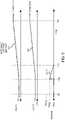
- FIG. 4 is an example timing diagram illustrating ramp control of a switching period during a first instance of a soft start according to embodiments herein.
- control information 104-11 such as one or more communications 104-1, 104-2 104-3, etc., from the soft start manager 141 to the controller 140 in a manner as previously discussed
- the controller 140 controls the switching period according to a ramp to ramp up the output voltage 123.
- the controller 140 implements a control rule of preventing a magnitude of the pulse width (PW) of activating the high side switch circuitry from falling below the threshold level TON-MIN.
- the switching period must be greater than a magnitude of the minimum ON-time value TON-MIN.
- the output voltage 123 is set to voltage V12.
- the soft start manager 141 starts the switching period (TPERIOD) at an initial value of TP402 at time T41.
- the soft start manager 141 ramps down a magnitude of the switching period used to produce the control signals 105 between time T41 (start value of TP402) and T42 (end value of TP401).
- the magnitude of the output voltage 123 ramps up in accordance with the reference voltage setpoint 235.
- the controller 140 Via implementation of the control information 104-11 indicating to ramp down the switching period (such as received in one or more communications), the controller 140 provides accurate regulation generating the magnitude of the output voltage 123 based on the reference voltage setpoint 235. In other words, as shown in in FIG. 4 , the magnitude of the output voltage 123 closely tracks the reference voltage setpoint 235 even at lower voltage levels between T41 and T43 without an undesirable plateau 456.
- the soft start manager 141 discontinues controlling the switching period TPERIOD via control information 104-11 and the controller 140 implements an appropriate switching frequency and pulse width (pulse width PW greater than TON-MIN) to control high side switch circuitry 125-1 to generate the output voltage 123.
- the soft start manager 141 starts from an initial switching period TP402 (corresponding to voltage magnitude V12) to a desired fixed switching period TP401 during the soft start (such as at least between time T41 and time T42).
- TP402 corresponding to voltage magnitude V12
- TP401 desired fixed switching period
- larger switching periods are implemented during the beginning of the ramp (such as nearer time T41) where the undesirable minimum pulse width plateau 456 would otherwise exist.
- the magnitude of the switching period decreases to value TP401, after which, the strict control is no longer needed.
- FIGS. 5 and 6 illustrate modification of the switching period ramp control when the initial magnitude of output voltage 123 is higher.
- the duration of ramping the switching period during soft start is shorter and a magnitude of the ramp starts at a lower value.
- FIG. 5 is an example timing diagram illustrating ramp control of a switching period during a second instance of a soft start according to embodiments herein.
- control information 104-12 (such as one or more communications 104-1, 104-2 104-3, etc.) from the soft start manager 141 to the controller 140
- the controller 140 controls a ramping of the switching period to ramp up the output voltage 123.
- the controller 140 implements a control rule of preventing a magnitude of the pulse width of activating the high side switch circuitry from falling below the threshold level TON-MIN.
- the output voltage 123 starts at a bias voltage of V22 (which is greater than V12).
- the output voltage 123 is set to voltage V22.
- the soft start manager 141 starts the switching period (TPERIOD) at an initial value of TP502 at time T52.
- the soft start manager 141 ramps down a magnitude of the switching period between time T52 (start value of TP502) and T53 (end value of TP401).
- the controller 140 provides accurate regulation generating the magnitude of the output voltage 123 based on the reference voltage setpoint 235. In other words, the magnitude of the output voltage 123 closely tracks the reference voltage setpoint 235 even at lower voltage levels between T52 and T53 without a plateau.
- the soft start manager 141 discontinues controlling the switching period TPERIOD via control information 104-12 and the controller 140 implements an appropriate switching frequency and pulse width (pulse width PW greater than TON-MIN) to control high side switch circuitry 125-1 to generate the output voltage 123.
- the soft start manager 141 starts from an initial switching period TP502 (corresponding to voltage V22) to a desired fixed switching period TP401 during the soft start (such as at least between time T52 and time T53).
- TP502 corresponding to voltage V22
- TP401 a desired fixed switching period
- larger switching periods are implemented during the beginning of the ramp (such as near time T52) where the undesirable minimum pulse width plateau would otherwise exist.
- FIG. 6 is an example timing diagram illustrating ramp control of a switching period during a third instance of a soft start according to embodiments herein.
- control information 104-13 (such as one or more communications 104-1, 104-2 104-3, etc.,) from the soft start manager 141 to the controller 140
- the controller 140 controls the switching period of generating the control signals during soft start to ramp up the output voltage 123.
- the controller 140 implements a control rule of preventing a magnitude of the pulse width of activating the high side switch circuitry from falling below the threshold level TON-MIN.
- the output voltage starts at a bias voltage of V32.
- the output voltage 123 is set to voltage V32.
- the soft start manager 141 starts the switching period (TPERIOD) at an appropriate initial value of TP602 (commensurate with the magnitude of the output voltage 123 being V32) at time T62.
- the soft start manager 141 ramps down a magnitude of the switching period between time T62 (start value of TP602) and T63 (end value of TP401).
- the controller 140 provides accurate regulation generating the magnitude of the output voltage 123 based on the reference voltage setpoint 235. In other words, the magnitude of the output voltage 123 closely tracks the reference voltage setpoint 235 even at lower voltage levels between T62 and T63 without a plateau.
- the soft start manager 141 discontinues controlling the switching period TPERIOD via control information 104-13 and the controller 140 implements an appropriate switching frequency and pulse width (pulse width PW greater than TON-MIN) to control high side switch circuitry 125-1 to generate the output voltage 123.
- the soft start manager 141 starts from an initial switching period TP602 (corresponding to voltage V32) to a desired fixed switching period TP401 during the soft start (such as at least between time T62 and time T63).
- TP602 corresponding to voltage V32
- TP401 a desired fixed switching period
- larger switching periods are implemented during the beginning of the ramp (such as near time T62) where the undesirable minimum pulse width plateau would otherwise exist.
- FIG. 7 is an example diagram illustrating implementation of soft start control according to embodiments herein.
- the soft start controller 741 varies the switching period TPERIOD during the soft start ramp to allow enforcement of the minimum pulse width. By varying the off time with the fixed minimum on time the ramp can be smoothed and avoid a plateau at the beginning of the ramp where typically with a fixed frequency and minimum on time would create one.
- the soft start manager 141 includes multiplexer 735, comparator 745, interrupt request generator 765, soft start controller 741, and threshold generator resource 725.
- the multiplexer 735 receives telemetry information such as output voltage and/or duty cycle.
- the soft start controller 741 selects which source to interrupt on and sets a comparator threshold TL-X from that source to generate the interrupt request such as signal 767.
- An interrupt handler in the soft start controller 741 (such as firmware) changes the switching period TPERIOD of generating control signals 105. Then sets second higher threshold from same source to create hysteresis. When dropping below threshold, the period is extended to its maximum and returned to its intended fixed frequency when above the hysteresis threshold.
- the soft start manager 141 receives input such as one or more of the output voltage 123, duty cycle 723 (ratio of pulse width of activating the high side switch circuitry with respect to the switching period or ratio of the output voltage 123 divided by the input voltage 121), etc.
- the magnitude of the monitored one or more parameters such as output voltage, duty cycle, etc., provides an indication whether the soft start controller 741 needs to implement switching period control as discussed herein such that the output voltage 123 closely tracks the reference voltage setpoint.
- the switch circuitry 125 of the power supply includes high side switch circuitry 125-1 (see FIG. 2 ).
- the selected switching period TPERIOD varies depending on magnitudes of the monitored one or more parameters.
- FIG. 7A illustrates generation of control signals 105 according to embodiments herein.
- the controller 140 can be configured to implement or include a PID (Proportional-Integral-Derivative) controller to convert the input voltage 121 into the output voltage 123; the soft start manager 141 potentially modifies settings (such as settings of gain value Kp, gain value Ki, gain value Kd) of the PID controller of the power supply 135 based on the monitored one or more parameters such as magnitude of the output voltage, duty cycle, etc.
- PID Proportional-Integral-Derivative
- the dynamic load manager 118-M or other suitable entity can be configured to generate a respective target voltage value VID indicating a respective magnitude of generating the output voltage 123.
- the soft start manager 141 varies a magnitude of the switching period (TPERIOD) applied to the switch circuitry 125 in the power supply 135 depending on the magnitude of the output voltage 123 or other suitable parameter such as duty cycle.
- the soft start manager 141 controls a magnitude of the switching period of generating the control signals 105 to be inversely related to the magnitude of the output voltage 123. For example, as shown via map information 750-1, the soft start manager 141 implements larger switching periods as the magnitude of the output voltage 123 decreases. This ensures accurate regulation at even lower magnitudes of the output voltage 123.
- the soft start controller 741 sets multiplexer 735 to monitor a magnitude of the output voltage 123.
- the soft start controller 741 also sets an appropriate value for the threshold value TL-X via control of the threshold generator resource 725. Based on a comparison of the magnitude of the monitored output voltage 123 to one or more different threshold values, the soft start controller 741 generates compare signal 755 indicating whether the magnitude of the output voltage 123 is greater than or less than the threshold value. In one embodiment, if the magnitude of the output voltage falls below a threshold value, the interrupt request generator 765 generates an interrupt request indicating the condition to the soft start controller 741.
- the soft start controller 741 implements the switching period (a.k.a., TPERIOD) settings in the map information 750-1 to control the switching period of control signals 105. For example, if the magnitude of the monitored output voltage 123 is between 150-200 mVDC, the soft start controller 141 sets the switching period (i.e., TPERIOD) to 2.5 microseconds; if the magnitude of the monitored output voltage 123 is between 100-150 mVDC, the soft start controller 141 sets the switching period to 3.33 microseconds; if the magnitude of the monitored output voltage 123 is between 50-100 mVDC, the soft start controller 141 sets the switching period to 5 microseconds; if the magnitude of the monitored output voltage 123 is between 0-50 mVDC, the soft start controller 141 sets the switching period to 10 microseconds; and so on.
- TPERIOD switching period
- further embodiments herein include implementing hysteresis to provide more stable operation of the soft start manager. For example, assume that the magnitude of the output voltage transitions from 175 mVDC to 125 mVDC. Using a threshold value of 150 mVDC to monitor the output voltage 123, the transition of the output voltage 123 from 175 mVDC to 125 mVDC triggers the soft start manager 141 to generate control information 104 that changes a switching period of controlling switches 125 from around 2.5 uS to 3.3 uS as indicated by map information 750-1. However, to prevent undesirable oscillations, the soft start manager 141 requires the magnitude of the output voltage 123 to raise above an adjusted threshold level of 160mvDC to switch from implementing a switching period of 3.3 uS to 2.5 uS.
- the power system 100 includes map information 750-2 indicating how to control settings of the switching period depending on a magnitude of the monitored duty cycle 723 in lieu of or in addition to the map information 750-1.
- the soft start manager 141 and corresponding soft start controller 741 can be configured to monitor the duty cycle 723 associated with control signal 105-1 and control a magnitude of the corresponding switching period TPERIOD based on the measurement of the duty cycle via implementation of map information 750 2.
- embodiments herein include, via the soft start manager 141, receiving one or more interrupt requests from the interrupt request generator 765 in response to detection (via comparator 745) of a condition in which the magnitude of the input (such as output voltage 123 or other suitable value) falls below a threshold value or in a particular range.
- Each of the received interrupt requests causes the soft start controller 741 of the soft start manager 141 to execute instructions to control (via generation of the control information 104) the switching period applied to the switch circuitry in the power supply 135.
- FIG. 8 is an example block diagram of a computer device for implementing any of the operations as discussed herein according to embodiments herein.
- computer system 800 (such as implemented by any of one or more resources such as controller 140, soft start manager 141, etc.) of the present example includes an interconnect 811 that couples computer readable storage media 812 such as a non-transitory type of media (or hardware storage media) in which digital information can be stored and retrieved, a processor 813 (e.g., computer processor hardware such as one or more processor devices), I/O interface 814, and a communications interface 817.
- computer readable storage media 812 such as a non-transitory type of media (or hardware storage media) in which digital information can be stored and retrieved
- processor 813 e.g., computer processor hardware such as one or more processor devices
- I/O interface 814 e.g., I/O interface 814
- I/O interface 814 provides connectivity to any suitable circuitry such as one or more voltage converters 165.
- Computer readable storage medium 812 can be any hardware storage resource or device such as memory, optical storage, hard drive, floppy disk, etc. In one embodiment, the computer readable storage medium 812 stores instructions and/or data used by the frequency controller application 340-1 to perform any of the operations as described herein.
- communications interface 817 enables the computer system 800 and processor 813 to communicate over a resource such as network 190 to retrieve information from remote sources and communicate with other computers.
- Soft start manager application 141-1 e.g., software, firmware, etc.
- Soft start manager application 141-1 can be configured to include instructions to implement any of the operations as discussed herein.
- processor 813 accesses computer readable storage media 812 via the use of interconnect 811 in order to launch, run, execute, interpret or otherwise perform the instructions in soft start manager application 141-1 stored on computer readable storage medium 812.
- Execution of the soft start manager application 141-1 produces processing functionality such as soft start manager process 141-2 in processor 813.
- the soft start manager process 141-2 associated with processor 813 represents one or more aspects of executing soft start manager application 141-1 within or upon the processor 813 in the computer system 800.
- computer system 800 can be a micro-controller device, logic, hardware processor, hybrid analog/digital circuitry, etc., configured to control a power supply and perform any of the operations as described herein.
- FIG. 9 is an example diagram illustrating a method of controlling a power converter according to embodiments herein.
- the soft start manager 141 receives input 102 (such as one or more magnitude output f the output voltage 123, duty cycle information, etc.) from a power supply 135.
- the input 102 is associated with generation of an output voltage 123 that powers a load 118.
- the soft start manager 141 In processing operation 920, the soft start manager 141 a magnitude of the input 102.
- the soft start manager 141 controls a switching period applied to switch circuitry 125 in the power supply 135.
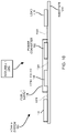
- FIG. 10 is an example diagram illustrating assembly of a power converter circuit on a circuit board according to embodiments herein.
- assembler 1040 receives a substrate 1010 (such as a circuit board).
- the assembler 1040 affixes (couples) the soft start manager 141, dynamic load 118, and power supply 135 (and corresponding components such as controller 140, power converter 165, etc.) to the substrate 1010.
- the assembler 1040 couples the soft start manager 141 to the power converter 135.
- the assembler 1040 couples the controller 140 to the power converter 165.
- components such as the controller 140, power converter 165, and corresponding components such as soft start manager 141, etc., associated with the power supply 135 can be affixed or coupled to the substrate 1010 in any suitable manner.
- one or more of the components in power system 100 can be soldered to the substrate, inserted into sockets disposed on the substrate 1010, etc.
- Circuit paths 1020, 1021, 1022, etc. may be disposed in cables providing connectivity between the different components such as between power supply 135 and the load 118.
- the dynamic load 118 is disposed on its own substrate independent of substrate 1010; the substrate of the dynamic load 118 is directly or indirectly connected to the substrate 1010.
- the soft start manager 141, controller 140, or any portion of the power supply 135 can be disposed on a standalone smaller board plugged into a socket of the substrate 1010.
- the assembler 1040 couples the power converter 165 to the load 118.
- the circuit path 1022 conveys the output voltage 123 (and corresponding output current) generated from the power converter 165 to the load 118.
- embodiments herein include a system comprising: a substrate 1010 (such as a circuit board, standalone board, mother board, standalone board destined to be coupled to a mother board, host, etc.); a soft start manager 141; a power converter 165 including corresponding components as described herein; and a dynamic load 118.
- the dynamic load 118 is powered based on conveyance of output voltage 123 and corresponding current conveyed over one or more circuit paths 1022 from the power converter 165 to the dynamic load 118.
- the dynamic load 118 can be any suitable circuit or hardware such as one or more CPUs (Central Processing Units), GPUs (Graphics Processing Unit) and ASICs (Application Specific Integrated Circuits such those including one or more Artificial Intelligence Accelerators), which can be located on the substrate 1010 or disposed at a remote location.
- CPUs Central Processing Units
- GPUs Graphics Processing Unit
- ASICs Application Specific Integrated Circuits such those including one or more Artificial Intelligence Accelerators
- An algorithm as described herein, and generally, is considered to be a self-consistent sequence of operations or similar processing leading to a desired result.
- operations or processing involve physical manipulation of physical quantities.
- quantities may take the form of electrical or magnetic signals capable of being stored, transferred, combined, compared or otherwise manipulated. It has been convenient at times, principally for reasons of common usage, to refer to such signals as bits, data, values, elements, symbols, characters, terms, numbers, numerals or the like. It should be understood, however, that all of these and similar terms are to be associated with appropriate physical quantities and are merely convenient labels.
Landscapes
- Engineering & Computer Science (AREA)
- Power Engineering (AREA)
- Dc-Dc Converters (AREA)
Abstract
Description
- One type of conventional power converter is a voltage regulator. In general, to maintain an output voltage within a desired range, a controller in the voltage regulator compares the magnitude of a generated output voltage to a setpoint reference voltage. Based on a respective error voltage derived from the comparison, the controller modifies a respective switching frequency and/or pulse width modulation associated with activating high side switch circuitry and low side switch circuitry in the voltage regulator.
- Conventional power converters can be configured to receive a voltage value (such as a so-called VID value) indicating a desired output voltage setting. The VID voltage value may vary over time depending on system operation. The conventional voltage regulator uses the VID value as the setpoint reference voltage. Accordingly, a device generating the VID value is able to control a magnitude of the output voltage.
- Further, in certain instances, a conventional voltage regulator includes so-called soft start capability. In general, soft start capability includes controlling a rate of ramping a voltage applied to a respective load, preventing damage to it.
- A method as defined in claim 1 and an apparatus as defined in claim 13 are provided. The dependent claims define further embodiments.
- Implementation of clean energy (or green technology) is very important to reduce human impact on the environment. In general, clean energy includes any evolving methods and materials to reduce an overall toxicity on the environment from energy consumption.
- This disclosure includes the observation that raw energy, such as received from green energy sources or non-green energy sources, typically needs to be converted into an appropriate form (such as desired AC voltage, DC voltage, etc.) before it can be used to power end devices such as servers, computers, mobile communication devices, wireless base stations, etc. In certain instances, energy is stored in a respective one or more battery resource. Alternatively, energy is received from a voltage generator or voltage source.
- Regardless of whether energy is received from green energy sources or non-green energy sources, it is desirable to make most efficient use of raw energy (such as storage and subsequent distribution) provided by such sources to reduce our impact on the environment. This disclosure contributes to reducing our carbon footprint and providing better use of energy via more efficient energy conversion.
- This disclosure further includes the observation that conventional implementation of soft start capability in a power converter suffers from deficiencies. For example, in certain instances, a power converter is programmed to implement a minimum fixed ON-time value of respective high side switch circuitry. The fixed ON-time value may be implemented during a standard operational mode as well as during implementation of a soft start mode. If a fixed frequency controller implements a programmed minimum ON-time value without skipping PWM pulses during soft start, a plateau voltage effect typically exists on the voltage ramp where a magnitude of the voltage at the plateau is the equivalent of the minimum duty cycle times voltage input.
- In other words, the magnitude of the output voltage generally cannot be controlled to a desired value for lower magnitudes of the output voltage near (where the plateau exists). With slower ramp slew rates, this issue is more prominently seen as the minimum ON time is enforced for much longer. This so-called voltage plateau effect prevents regulation of the output voltage at lower voltage levels, resulting in limited power converter performance.
- Embodiments herein include novel ways of controlling a switching period during implementation of a minimum ON-time value to produce an output voltage via a power supply.
- More specifically, embodiments herein include an apparatus such as a power supply including a soft start manager. The soft start manager controls generation of an output voltage. For example, the soft start manager receives input (such as one or more parameters of information) from the power supply; the input (such as an input parameter) is associated with generation of an output voltage that powers a load.
- The soft start manager monitors a magnitude of the input associated with one or more parameters. Based at least in part on the magnitude of the input, the soft start manager controls a switching period applied to switch circuitry in the power supply.
- Note that the input (such as one or more input parameters) can be any suitable one or more parameters associated with the power supply. For example, in one embodiment, the input parameter monitored by the soft start manager is a magnitude of the output voltage. Additionally, or alternatively, the input parameter is a duty cycle of activating the switch circuitry in the power supply.
- In one embodiment, the duty cycle represents a ratio value of an input voltage and the output voltage; the power supply converts the input voltage into the output voltage.
- In yet further example embodiments, the switch circuitry of the power supply as discussed herein is high side switch circuitry. In one embodiment, the power supply is programmed to implement a minimum pulse width of activating the high side switch circuitry during soft start of the output voltage. Control of the switching period during soft start provides better regulation of the output voltage.
- In further example embodiments, the power supply includes or implements a PID (Proportional-Integral-Derivative) controller to convert an input voltage into the output voltage; the soft start manager modifies settings of the PID controller of the power supply based on the monitored parameters (such as magnitude of the output voltage, duty cycle, input voltage, etc.).
- Further embodiments herein include, via the soft start manager, controlling activation of the switch circuitry and generation of the output voltage during soft start of ramping the output voltage up or down to a target voltage.
- Still further example embodiments herein include, via the soft start manager, varying a magnitude of the switching period applied to the switch circuitry in the power supply depending on the magnitude of the output voltage.
- In yet further example embodiments, the soft start manager controls ramping of the magnitude of the switching period over time; the ramping of the switching period results in ramping of the magnitude of the output voltage. In one embodiment, the ramping of the magnitude of the switching period over time substantially aligns or coincides with ramping of a magnitude of the output voltage. In other words, a magnitude of the output voltage ramps as a magnitude of the switching period is ramped over time.
- In further example embodiments, a magnitude of the switching period is inversely related to the magnitude of the output voltage. For example, the switching period is larger for lower output voltage magnitudes. Note that the operations as discussed herein can be implemented in any type of controller such as current mode controller, voltage mode controller, etc.
- Yet further embodiments herein include, via the soft start manager, monitor an input voltage used by the power supply to produce the output voltage; and control the switching period applied to the switch circuitry in the power supply based on the magnitude of the input voltage and/or the magnitude of the output voltage.
- To provide stable operation of generating the output voltage, the soft start manager implements hysteresis during control of the switching period.
- In yet further example embodiments, the soft start manager repeatedly communicates switching period control information to the power supply. The soft start manager receives feedback from the power supply; the feedback indicates a status of executing the switching period control information by the power supply.
- Further example embodiments herein include, via the soft start manager, receiving one or more interrupt request notifications in response to detection of a condition in which the magnitude of the input parameter falls below a threshold value. In such an instance, each of the received interrupt requests causes the soft start manager to execute instructions to control/adjust the switching period applied to the switch circuitry in the power supply.
- These and other more specific embodiments are disclosed in more detail below.
- Note that although embodiments as discussed herein are applicable to power converters, the concepts disclosed herein may be advantageously applied to any other suitable topologies as well as general power supply control applications.
- Note that any of the resources as discussed herein can include one or more computerized devices, mobile communication devices, servers, base stations, wireless communication equipment, communication management systems, workstations, user equipment, handheld or laptop computers, or the like to carry out and/or support any or all of the method operations disclosed herein. In other words, one or more computerized devices or processors can be programmed and/or configured to operate as explained herein to carry out the different embodiments as described herein.
- Yet other embodiments herein include software programs to perform the steps and operations summarized above and disclosed in detail below. One such embodiment comprises a computer program product including a non-transitory computer-readable storage medium (i.e., any computer readable hardware storage medium) on which software instructions are encoded for subsequent execution. The instructions, when executed in a computerized device (hardware) having a processor, program and/or cause the processor (hardware) to perform the operations disclosed herein. Such arrangements are typically provided as software, code, instructions, and/or other data (e.g., data structures) arranged or encoded on a non-transitory computer readable storage medium such as an optical medium (e.g., CD-ROM), floppy disk, hard disk, memory stick, memory device, etc., or other a medium such as firmware in one or more ROM, RAM, PROM, etc., or as an Application Specific Integrated Circuit (ASIC), etc. The software or firmware or other such configurations can be installed onto a computerized device to cause the computerized device to perform the techniques explained herein.
- Accordingly, embodiments herein are directed to methods, systems, computer program products, etc., that support operations as discussed herein.
- One embodiment herein includes a computer readable storage medium and/or system having instructions stored thereon.
- The instructions, when executed by computer processor hardware, cause the computer processor hardware (such as one or more co-located or disparately located processor devices) to: during soft start: receive an input parameter from a power supply, the input parameter associated with generation of an output voltage that powers a load; monitor a magnitude of the input parameter; and based at least in part on the magnitude of the input parameter, control a switching period applied to switch circuitry in the power supply.
- The ordering of the steps above has been added for clarity sake. Note that any of the processing steps as discussed herein can be performed in any suitable order.
- Other embodiments of the present disclosure include software programs and/or respective hardware to perform any of the method embodiment steps and operations summarized above and disclosed in detail below.
- It is to be understood that the system, method, apparatus, instructions on computer readable storage media, etc., as discussed herein also can be embodied strictly as a software program, firmware, as a hybrid of software, hardware and/or firmware, or as hardware alone such as within a processor (hardware or software), or within an operating system or a within a software application.
- As discussed herein, techniques herein are well suited for use in the field of implementing one or more voltage converters to deliver current to a load. However, it should be noted that embodiments herein are not limited to use in such applications and that the techniques discussed herein are well suited for other applications as well.
- Additionally, note that although each of the different features, techniques, configurations, etc., herein may be discussed in different places of this disclosure, it is intended, where suitable, that each of the concepts can optionally be executed independently of each other or in combination with each other. Accordingly, the one or more present inventions as described herein can be embodied and viewed in many different ways.
- Also, note that this preliminary discussion of embodiments herein (BRIEF DESCRIPTION OF EMBODIMENTS) purposefully does not specify every embodiment and/or incrementally novel aspect of the present disclosure or claimed invention(s). Instead, this brief description only presents general embodiments and corresponding points of novelty over conventional techniques. For additional details and/or possible perspectives (permutations) of the invention(s), the reader is directed to the Detailed Description section (which is a further summary of embodiments) and corresponding figures of the present disclosure as further discussed below.
-
-
FIG. 1 is an example general diagram of a power supply and implementation of soft start management according to embodiments herein. -
FIG. 2 is an example diagram illustrating operation of a power converter and corresponding generation of an output voltage according to embodiments herein. -
FIG. 3 is an example diagram illustrating control of a switching period according to embodiments herein. -
FIG. 4 is an example timing diagram illustrating ramp control of a switching period during a first instance of implementing soft start control according to embodiments herein. -
FIG. 5 is an example timing diagram illustrating ramp control of a switching period during a second instance of implementing soft start control according to embodiments herein. -
FIG. 6 is an example timing diagram illustrating ramp control of a switching period during a third instance of implementing soft start control according to embodiments herein. -
FIG. 7 is an example diagram illustrating implementation of soft start control depending on one or more monitored parameters according to embodiments herein. - FIG. 7A is an example timing diagram illustrating generation of multiple control signals according to embodiments herein.
-
FIG. 8 is an example diagram illustrating computer processor hardware and related software instructions that execute methods according to embodiments herein. -
FIG. 9 is an example diagram illustrating a method according to embodiments herein. -
FIG. 10 is an example diagram illustrating assembly of a circuit according to embodiments herein. - The foregoing and other objects, features, and advantages of the invention will be apparent from the following more particular description of preferred embodiments herein, as illustrated in the accompanying drawings in which like reference characters refer to the same parts throughout the different views. The drawings are not necessarily to scale, with emphasis instead being placed upon illustrating the embodiments, principles, concepts, etc.
- As previously discussed, embodiments herein include an apparatus to control a period of operating switches in a power supply to generate an output voltage. The apparatus includes a power converter and a soft start manager such as implemented via hardware, software, or a combination of hardware and software. High side switch circuitry in the power converter requires activation equal to or greater than a minimal ON-time value. Operation of the soft start manager provides improved regulation of the power converter, especially at lower voltage magnitudes.
- More specifically, during operation, the soft start manager receives input (one or more parameters such as output voltage, duty cycle, input voltage, etc.) associated with a power converter. In one embodiment, the input is an input parameter. As its name suggests, the power converter converts the input voltage into an output voltage that powers a load. The soft start manager monitors a magnitude of the received input (such as one or more parameters, namely, output voltage, duty cycle, input voltage, etc.). Based at least in part on the magnitude of the monitored one or more input parameters, the soft start manager controls a switching period applied to switch circuitry in the power supply. Control of the switching period provides improved power conversion.
- Now, more specifically,
FIG. 1 is an example general diagram of a power supply and corresponding soft start manager according to embodiments herein. - In this example embodiment, the
power system 100 includessoft start manager 141,power supply 135, anddynamic load 118. -
Power supply 135 includescontroller 140 andpower converter 165. -
Power converter 165 includes one ormore switches 125 controlled by thecontroller 140 via control signals 105. - During operation, via control of
switches 125 based at least in part on thecontrol information 104 produced by thesoft start manager 141, thepower converter 165 converts the input voltage 121 (such as any suitable DC input voltage) into the output voltage 123 (such as any suitable DCC output voltage). The output voltage 123 (Vout) and corresponding generated output current (i.e., ILOAD) supply power to theload 118. - As further shown, the
soft start manager 141 receives one or more signals such as feedback signals (input 102 such as one or more input parameters) associated with thepower converter 165. For example, thesoft start manager 141 receivesinput 102 such as one or more parameters (output voltage, duty cycle, input voltage, etc.) associated with thepower supply 135. - As further discussed herein, the
soft start manager 141 controls generation of theoutput voltage 123 based on current operational conditions of thepower supply 135. For example, thesoft start manager 141 receives input 102 (such as feedback) from thepower supply 135. Thesoft start manager 141 monitors a magnitude of the input 102 (one or more parameters associated with power supply 135). - Based at least in part on the magnitude of the
input 102, thesoft start manager 141 controls one or more parameters such as including a switching period (such as captured by controller information 104) applied to one ormore switches 125 in thepower supply 135, providing improved regulation of generating theoutput voltage 123. - In one embodiment, the
controller 140 is configured to receive a control value TON-MIN, indicating a minimum ON-time value in which to control respective high side switch circuitry in thepower supply 135. Implementation of the control TON-MIN ensures proper operation of thepower supply 135 and prevents damage to thepower supply 135. - Note that the
power supply 135 operates at any suitable switching frequency between 50KHz and 2MHz or other any other suitable switching frequency ranges. - As further discussed herein, embodiments herein include, via the
soft start manager 141, creating a monotonic soft start ramp of theoutput voltage 123 and enforcing minimum PWM pulse widths (as indicated by the ON-time value TON-MIN) by modulating the switching period of controllingswitches 125 in thepower supply 135. Modulation of the switching period during soft start provides accurate generation of theoutput voltage 123, even at low voltage magnitudes, where a longer switching period allows the small duty cycle to be more easily generated and the low current ripple is more easily tolerated. In one embodiment, as discussed herein, thesoft start manager 141 implements a switching period that is greater than the switching period implemented during nominal operation (such as a non-soft start mode when the voltage is above a threshold level and soft start ramping is not needed). In other words, as discussed herein, thesoft start manager 141 implements the longer switching periods during soft start ramping of theoutput voltage 123. -
FIG. 2 is an example diagram illustrating operation of a power converter and generation of an output voltage according to embodiments herein. - As previously discussed, the
power converter 165 andcorresponding power supply 135 can be configured as any suitable type of power converter or power converter system. - In this non-limiting example embodiment, the power converter phase 165-1 is configured as a buck converter. Power converter phase 165-1 includes voltage source 220 (providing input voltage 121), switch Q1 (high side switch circuitry 125-1), switch Q2 (low side switch circuitry 125-2), inductor 144-1, and output capacitor 136 (such as one or more capacitors).
- Switches 125 (Q1, Q2, etc.) can be implemented in any suitable manner. In one embodiment, each of the
switches 125 is a so-called field effect transistor. Any suitable type ofswitches 125 can be used to provide switching as discussed herein. - Note that the
power supply 100 includes any number of power converters 165 (voltage regulators such as power converter 165-1, power converter 165-2, etc.) disposed in parallel to produce theoutput voltage 123. Each voltage converter such as power converter 165-2 operates in a similar manner as power converter 165-1. Thepower converters 165 can be operated in or out of phase with respect to each other. - Although the power converter 165-1 in
FIG. 2 is shown as a buck converter configuration, note again that thepower converter 165 can be instantiated as any suitable type of voltage converter and include any number of phases, providing regulation of arespective output voltage 123 as described herein. - As further shown in this example embodiment, the switch Q1 of power converter 165-1 is connected in series with switch Q2 between the
input voltage source 220 and corresponding ground reference. - For example, the drain node (D) of the switch Q1 is connected to the
voltage source 220 to receiveinput voltage 121. Theswitch controller 140 drives the gate node (G) of switch Q1 with control signal 105-1. - The source node (S) of the switch Q1 is connected to the drain node (D) of the switch Q2 at
node 296. Theswitch controller 140 drives the gate node (G) of switch Q2 with control signal 105-2. The source node (S) of the switch Q2 is connected to ground. - As previously discussed, the power converter 165-1 further includes inductor 144-1. Inductor 144-1 extends from the
node 296 to theoutput capacitor 136 anddynamic load 118. - Via switching of the switches Q1 and Q2 via respective control signal 105-1 (applied to gate G of switch Q1) and control signal 105-2 (applied to gate G of switch Q2), the
node 296 coupling the source (S) node of switch Q1 and the drain (D) node of switch Q2 provides output current through the inductor 144, resulting in generation of theoutput voltage 123 and corresponding output current ILOAD powering theload 118 and energizingcapacitors 136. - In general, the magnitude of the current ILOAD is equal to a magnitude of the output current through inductor 144-1.
Output capacitor 136 reduces a ripple voltage associated with theoutput voltage 123. - In further example embodiments, as previously discussed, the
controller 140 controls switching of the switches Q1 and Q2 based on one or more feedback parameters. For example, thecontroller 140 can be configured to receive output voltage feedback signal 123-1 derived from theoutput voltage 123 supplied to power theload 118 as previously discussed inFIG. 1 . The output voltage feedback signal 123-1 can be theoutput voltage 123 itself or a proportional derivative voltage value thereof using a resistor divider. - Referring again to
FIG. 2 , via thecomparator 250, thecontroller 140 compares the output voltage feedback signal 123-1 (such asoutput voltage 123 itself or derivative, or proportional signal) to thereference voltage setpoint 235. - As previously discussed, the
reference voltage setpoint 235 is a desired setpoint in which to control a magnitude of theoutput voltage 123 during load-line regulation implemented by thepower supply 135. - In one embodiment, the voltage manager 118-M in or associated with the
dynamic load 118 provides control information or feedback (such as a VID value) indicating a desiredreference voltage setpoint 235. In other words, the voltage manager 118-M can be configured to provide feedback to thecontroller 140 indicating a magnitude in which to produce theoutput voltage 123. In further example embodiments, the feedback such as VID value is used to produce thereference voltage setpoint 235. - As further shown, the amplifier or
comparator 250 produces arespective error voltage 255 based on a difference between the output voltage feedback signal 123-1 and thereference voltage 235. A magnitude of theerror voltage 255 generated by the amplifier orcomparator 250 varies depending upon the degree to which the magnitude of theoutput voltage 123 is in or out of regulation (with respect to the reference voltage setpoint 235). - In one non-limiting example embodiment, the
controller 140 includes PID controller 258 (control function). ThePID controller 258 includes a P-component (Proportional component), I-component (Integral component), and a D-component (Derivative component) as known in the art to control operation of switches 125 (Q1 and Q2). In voltage mode control, the output of the PID can proportionally control the duty cycle or ON-time of the PWM, and the PWM pulses may be generated at a fixed or variable switching period or frequency. In current mode control, the output of the PID sets the target average current or peak current in the inductor 144-1, and the PWM pulse is dependent on the current sense information, such that the duty cycle or ON time of the PWM is generated based on the PID output and the current sense, with the PWM pulses being generated at fixed or variable switching period or frequency. - In further example embodiments, the
control information 104 includes PID settings (so-called tuning parameters such as gain value Kp applied to the P-component stage, a gain value Ki applied to the I-component stage, and a gain value Kd applied to the D-component stage) produced by thesoft start manager 141. Note that the PID settings (gain value Kp, gain value Ki, gain value Kd) vary depending on the monitoredinput 102 and conditions associated with producing theoutput voltage 123. - As further shown, the PWM (Pulse Width Modulation)
generator 260 of thecontroller 140 controls operation of switching the switches Q1 and Q2 based upon the magnitude of the signal 256 (such as control output) from thePID controller 258. - For example, in general, if the error voltage 255 (and control signal 256) indicates that the output voltage 123 (of the power converter 165-1) becomes less than a magnitude of the
reference voltage setpoint 235, thePWM generator 260 increases a duty cycle or frequency of activating the high side switch Q1 (thus decreasing a duty cycle of activating the low-side switch Q2) in a respective switch control cycle. - Conversely, if the
error voltage 256 indicates that the output voltage 123 (of the power converter 165-1) becomes greater than a magnitude of thereference voltage setpoint 235, thePWM generator 260 decreases a duty cycle or frequency of activating the high side switch circuitry Q1 (thus increasing a duty cycle of activating the low-side switch Q2) in a respective switching control cycle. - As is known in the art, the
controller 140 controls each of the switches Q1 and Q2 ON and OFF at different times to prevent short-circuiting of theinput voltage 121 to the ground reference voltage. For example, for a first portion of the control cycle, when the switch Q1 is activated to an ON state, the switch Q2 is deactivated to an OFF state. Conversely, when the switch Q1 is deactivated to an OFF state, the switch Q2 is activated to an ON state. - Note that the controller 140 (via PWM generator 260) implements a dead time (both switches Q1 and Q2 OFF) between state ON-OFF and OFF-ON state transitions to prevent shorting of the
input voltage 121 to the ground reference. - Via variations in the pulse with modulation (and/or frequency modulation) of controlling the respective switches Q1 and Q2, the
controller 140 controls generation of theoutput voltage 123 such that theoutput voltage 123 remains within a desired voltage range with respect to thereference voltage setpoint 235. - The magnitude of current 122 through the inductor 144-1 increases when the high-side switch Q1 (such as one or more field effect transistor or other suitable component) is ON and low-side switch Q2 (such as one or more field effect transistor or other suitable component) is OFF; the magnitude of current 122 through the inductor 144-1 decreases when the high-side switch Q1 is OFF and Q2 is ON.
- As previously discussed, the
control information 104 received from thesoft start manager 141 includes data indicating a switching period of producing the respective control signals 105. For example, as previously discussed, thesoft start manager 141 monitors theinput 102 such as one or more of the magnitude of theoutput voltage 123, magnitude of theinput voltage 121, duty cycle of operatingswitches 125, etc. As further discussed below, the control of the switching period (or switching frequency) of generatingcontrol signals 105 can be achieved in any of multiple different ways. -
FIG. 3 is an example diagram illustrating control of a switching period according to embodiments herein. - As shown in this example embodiment, the processor 355 (hardware) implements
control function 348 and thesoft start manager 141. - Initially, an
entity 108 such as an enable pin associated with theprocessor 355 receivessignal 301, causing startup of thecontrol function 348. In response to receiving theinput 301, thecontrol function 348 generates a respective interruptrequest 302. The interrupt request causes execution of thesoft start manager 141 to change a magnitude of theoutput voltage 123 to a desired value. This may include ramping a magnitude of theoutput voltage 123. - The
soft start manager 141 monitors the one or more input parameters such asoutput voltage 123,input voltage 121, duty cycle, etc., associated with generating theoutput voltage 123. Based on the one or more monitored parameters, the soft start manager generates control information 104-1 such as settings (such as one or more of switching period settings, PID settings, etc.) to be applied to thecontroller 140. - Via communications 104-1 and corresponding control information from the
soft start manager 141 to thecontroller 140, thesoft start manager 141 notifies thecontroller 140 of an initial switching period value to be applied to the control signals 105. In one embodiment, as further shown inFIGS. 4-6 , the initial setting (magnitude) of the switching period depends on a magnitude (or current bias) of theoutput voltage 123. Note that theoutput voltage 123 may start at any suitable magnitude or voltage value. - Via communications 304-1 (such as an interrupt request or other suitable signaling to the soft start manager 141), the
controller 141 acknowledges receipt of the initial switching period value and control of thesignals 105 using the initial switching period value as indicated by communication 104-1. In one embodiment, thecontroller 141 generates the control signals with an ON-time pulse width value (of activating the high side switch circuitry 125-1) equal to or greater than the minimal pulse width (TON-MIN) to protect the power stage. - Via communications 104-2 and corresponding control information, the
soft start manager 141 notifies the controller to decrement a magnitude of the switching period currently used to generate the controls signals 105. - Via communications 304-2 (such as an interrupt request or other suitable signaling to the soft start manager 141), the
controller 141 acknowledges receipt of the decrement command and implemented reduction in the initial switching period value (used to produce the control signals 105) as indicated by communication 104-2. In one embodiment, thecontroller 141 generates the control signals with an ON-time pulse width value (of activating the high side switch circuitry 125-1) equal to or greater than the minimal pulse width (TON-MIN) to protect the power stage. The application of reduced switching period increases a magnitude of theoutput voltage 123. - Via communications 104-3 and corresponding control information, the
soft start manager 141 notifies the controller to further decrement a magnitude of the switching period currently used to generate the controls signals 105. - Via communications 304-3 (such as an interrupt request or other suitable signaling to the soft start manager 141), the
controller 141 acknowledges receipt of the decrement command and implemented reduction in the initial switching period value (used to produce the control signals 105) as indicated by communication 104-3. For example, thecontroller 140 notifies thesoft start manager 141 when a programmed count is reached, and applied switching period is decremented by programmed slope time unit. In one embodiment, thecontroller 141 generates the control signals with an ON-time pulse width value (of activating the high side switch circuitry 125-1) equal to or greater than the minimal pulse width (TON-MIN). The application of reduced switching period further increases a magnitude of theoutput voltage 123. - Thus, the
soft start manager 141 communicates switching period control information to thepower supply 135. Thesoft start manager 141 receives feedback from thepower supply 135; the feedback indicates a status of executing the switching period control information by the power supply. - Further, via communications 310, the
controller 140 notifies thesoft start manager 141 that the target switching period has been reached. - Via
communications 320, thesoft start manager 141 notifies thecontroller 140 that ramping has completed and that thecontroller 140 is able to operate in a free mode in which the counter controls the switching frequency and/or pulse width (PW) to generate theoutput voltage 123 without being controlled by thesoft start manager 141. In other words, after completion of soft start, the controller no longer relies on thesoft start manager 141 to control the switching period. - In this manner, the interrupt requests continue to provide a ramp downward until initial max period has ramped to a target steady state switching period, avoiding occurrence of glitches or large undesirable variations (voltage error) in in the
output voltage 123. In one embodiment, as shown in subsequentFIGS. 4-6 , the firmware executed by the processor 355 (such ascontrol function 348 and/or soft start manager 141) disables interrupt request generation when the ramp down of the switching period is completed. - In one embodiment, any faults will return the switching period back to the initial maximum switching period value for a retry. As previously discussed, in one embodiment, different PID settings (such as gain value Kp, gain value Ki, gain value Kd) are applied during soft start and ramping of the switching period to account for the changes in the switching period (switching frequency) used to generate the control signals 105.
- Additional details of controlling the switching period are shown in the following
FIGS. 4-6 . -
FIG. 4 is an example timing diagram illustrating ramp control of a switching period during a first instance of a soft start according to embodiments herein. - In one embodiment, via generation and communication of control information 104-11 (such as one or more communications 104-1, 104-2 104-3, etc.,) from the
soft start manager 141 to thecontroller 140 in a manner as previously discussed, thecontroller 140 controls the switching period according to a ramp to ramp up theoutput voltage 123. In other words, thecontroller 140 implements a control rule of preventing a magnitude of the pulse width (PW) of activating the high side switch circuitry from falling below the threshold level TON-MIN. The switching period must be greater than a magnitude of the minimum ON-time value TON-MIN. - More specifically, at time T41, the
output voltage 123 is set to voltage V12. In response to the input 101 (or other suitable command information) indicating to ramp theoutput voltage 123 from current voltage magnitude V12 to a target value such as magnitude VTARGET42, thesoft start manager 141 starts the switching period (TPERIOD) at an initial value of TP402 at time T41. In a manner as discussed herein, in accordance with control information 104-11, thesoft start manager 141 ramps down a magnitude of the switching period used to produce the control signals 105 between time T41 (start value of TP402) and T42 (end value of TP401). As further shown, the magnitude of theoutput voltage 123 ramps up in accordance with thereference voltage setpoint 235. Via implementation of the control information 104-11 indicating to ramp down the switching period (such as received in one or more communications), thecontroller 140 provides accurate regulation generating the magnitude of theoutput voltage 123 based on thereference voltage setpoint 235. In other words, as shown in inFIG. 4 , the magnitude of theoutput voltage 123 closely tracks thereference voltage setpoint 235 even at lower voltage levels between T41 and T43 without anundesirable plateau 456. - After time T42, the
soft start manager 141 discontinues controlling the switching period TPERIOD via control information 104-11 and thecontroller 140 implements an appropriate switching frequency and pulse width (pulse width PW greater than TON-MIN) to control high side switch circuitry 125-1 to generate theoutput voltage 123. - Thus, in one embodiment, the
soft start manager 141 starts from an initial switching period TP402 (corresponding to voltage magnitude V12) to a desired fixed switching period TP401 during the soft start (such as at least between time T41 and time T42). During the ramping down of the switching period, larger switching periods are implemented during the beginning of the ramp (such as nearer time T41) where the undesirable minimumpulse width plateau 456 would otherwise exist. Eventually, the magnitude of the switching period decreases to value TP401, after which, the strict control is no longer needed. - Following
FIGS. 5 and6 illustrate modification of the switching period ramp control when the initial magnitude ofoutput voltage 123 is higher. In such an instance, the duration of ramping the switching period during soft start is shorter and a magnitude of the ramp starts at a lower value. -
FIG. 5 is an example timing diagram illustrating ramp control of a switching period during a second instance of a soft start according to embodiments herein. - In one embodiment, via generation and communication of control information 104-12 (such as one or more communications 104-1, 104-2 104-3, etc.) from the
soft start manager 141 to thecontroller 140, thecontroller 140 controls a ramping of the switching period to ramp up theoutput voltage 123. In other words, thecontroller 140 implements a control rule of preventing a magnitude of the pulse width of activating the high side switch circuitry from falling below the threshold level TON-MIN. - More specifically, between time T51 and T52, the
output voltage 123 starts at a bias voltage of V22 (which is greater than V12). At time T52, theoutput voltage 123 is set to voltage V22. In response to input indicating to soft start ramp theoutput voltage 123 from voltage V22 to a target value such as VTARGET52, thesoft start manager 141 starts the switching period (TPERIOD) at an initial value of TP502 at time T52. In a manner as discussed herein, in accordance with control information 104-12, thesoft start manager 141 ramps down a magnitude of the switching period between time T52 (start value of TP502) and T53 (end value of TP401). As further shown, the magnitude of theoutput voltage 123 ramps up (or tracks) in accordance with thereference voltage setpoint 235. Via implementation of the control information 104-12 indicating to ramp down the switching period between time T52 and T53 (such as received in one or more communications), thecontroller 140 provides accurate regulation generating the magnitude of theoutput voltage 123 based on thereference voltage setpoint 235. In other words, the magnitude of theoutput voltage 123 closely tracks thereference voltage setpoint 235 even at lower voltage levels between T52 and T53 without a plateau. - After time T53, the
soft start manager 141 discontinues controlling the switching period TPERIOD via control information 104-12 and thecontroller 140 implements an appropriate switching frequency and pulse width (pulse width PW greater than TON-MIN) to control high side switch circuitry 125-1 to generate theoutput voltage 123. - Thus, in one embodiment, the
soft start manager 141 starts from an initial switching period TP502 (corresponding to voltage V22) to a desired fixed switching period TP401 during the soft start (such as at least between time T52 and time T53). During the ramping down of the switching period used to generatecontrol signals 105, larger switching periods are implemented during the beginning of the ramp (such as near time T52) where the undesirable minimum pulse width plateau would otherwise exist. -
FIG. 6 is an example timing diagram illustrating ramp control of a switching period during a third instance of a soft start according to embodiments herein. - In one embodiment, via generation and communication of control information 104-13 (such as one or more communications 104-1, 104-2 104-3, etc.,) from the
soft start manager 141 to thecontroller 140, thecontroller 140 controls the switching period of generating the control signals during soft start to ramp up theoutput voltage 123. In other words, thecontroller 140 implements a control rule of preventing a magnitude of the pulse width of activating the high side switch circuitry from falling below the threshold level TON-MIN. - More specifically, between time T61 and T62, the output voltage starts at a bias voltage of V32. At time T62, the
output voltage 123 is set to voltage V32. In response to input indicating to soft start ramp theoutput voltage 123 from voltage V32 to a target value such as VTARGET62, thesoft start manager 141 starts the switching period (TPERIOD) at an appropriate initial value of TP602 (commensurate with the magnitude of theoutput voltage 123 being V32) at time T62. In a manner as discussed herein, in accordance with control information 104-13, thesoft start manager 141 ramps down a magnitude of the switching period between time T62 (start value of TP602) and T63 (end value of TP401). As further shown, the magnitude of theoutput voltage 123 ramps up in accordance with thereference voltage setpoint 235. Via implementation of the control information 104-13 indicating to ramp down the switching period (such as received in one or more communications), thecontroller 140 provides accurate regulation generating the magnitude of theoutput voltage 123 based on thereference voltage setpoint 235. In other words, the magnitude of theoutput voltage 123 closely tracks thereference voltage setpoint 235 even at lower voltage levels between T62 and T63 without a plateau. - After time T63, the
soft start manager 141 discontinues controlling the switching period TPERIOD via control information 104-13 and thecontroller 140 implements an appropriate switching frequency and pulse width (pulse width PW greater than TON-MIN) to control high side switch circuitry 125-1 to generate theoutput voltage 123. - Thus, in one embodiment, the
soft start manager 141 starts from an initial switching period TP602 (corresponding to voltage V32) to a desired fixed switching period TP401 during the soft start (such as at least between time T62 and time T63). During the ramping down of the switching period, larger switching periods are implemented during the beginning of the ramp (such as near time T62) where the undesirable minimum pulse width plateau would otherwise exist. -
FIG. 7 is an example diagram illustrating implementation of soft start control according to embodiments herein. - As previously discussed, embodiments herein include generating a monotonic startup voltage ramp and enforcing a minimum pulse width PW = TON-MIN during soft start. The
soft start controller 741 varies the switching period TPERIOD during the soft start ramp to allow enforcement of the minimum pulse width. By varying the off time with the fixed minimum on time the ramp can be smoothed and avoid a plateau at the beginning of the ramp where typically with a fixed frequency and minimum on time would create one. - In this example embodiment, the
soft start manager 141 includesmultiplexer 735,comparator 745, interruptrequest generator 765,soft start controller 741, andthreshold generator resource 725. - In one embodiment, the
multiplexer 735 receives telemetry information such as output voltage and/or duty cycle. Thesoft start controller 741 selects which source to interrupt on and sets a comparator threshold TL-X from that source to generate the interrupt request such assignal 767. An interrupt handler in the soft start controller 741 (such as firmware) changes the switching period TPERIOD of generating control signals 105. Then sets second higher threshold from same source to create hysteresis. When dropping below threshold, the period is extended to its maximum and returned to its intended fixed frequency when above the hysteresis threshold. - Now, more specifically, via the input of
multiplexer 735, thesoft start manager 141 receives input such as one or more of theoutput voltage 123, duty cycle 723 (ratio of pulse width of activating the high side switch circuitry with respect to the switching period or ratio of theoutput voltage 123 divided by the input voltage 121), etc. - The magnitude of the monitored one or more parameters such as output voltage, duty cycle, etc., provides an indication whether the
soft start controller 741 needs to implement switching period control as discussed herein such that theoutput voltage 123 closely tracks the reference voltage setpoint. - As previously discussed, the
switch circuitry 125 of the power supply includes high side switch circuitry 125-1 (seeFIG. 2 ). Thepower supply 135 implements a minimum pulse width PW = TON-MIN of activating the high side switch circuitry 125-1 during soft start of theoutput voltage 123. The selected switching period TPERIOD varies depending on magnitudes of the monitored one or more parameters. - Note that FIG. 7A illustrates generation of
control signals 105 according to embodiments herein. As discussed herein, thesoft start manager 141 and corresponding switched-capacitor converter 741 controls a magnitude of the switching period, TPERIOD, during certain conditions such as when theoutput voltage 123 falls below a threshold value of 200 mVDC or other suitable value as indicated by map information 750-1. While implementing the minimum pulse width PW = TON-MIN, thesoft start manager 141 varies a magnitude of the switching period TPERIOD based on any of one or more monitored parameters as previously discussed. - In a similar manner as previously discussed, the
controller 140 can be configured to implement or include a PID (Proportional-Integral-Derivative) controller to convert theinput voltage 121 into theoutput voltage 123; thesoft start manager 141 potentially modifies settings (such as settings of gain value Kp, gain value Ki, gain value Kd) of the PID controller of thepower supply 135 based on the monitored one or more parameters such as magnitude of the output voltage, duty cycle, etc. - Yet further, note that the dynamic load manager 118-M or other suitable entity can be configured to generate a respective target voltage value VID indicating a respective magnitude of generating the
output voltage 123. Thesoft start manager 141 varies a magnitude of the switching period (TPERIOD) applied to theswitch circuitry 125 in thepower supply 135 depending on the magnitude of theoutput voltage 123 or other suitable parameter such as duty cycle. - In one embodiment, the
soft start manager 141 controls a magnitude of the switching period of generating the control signals 105 to be inversely related to the magnitude of theoutput voltage 123. For example, as shown via map information 750-1, thesoft start manager 141 implements larger switching periods as the magnitude of theoutput voltage 123 decreases. This ensures accurate regulation at even lower magnitudes of theoutput voltage 123. - More specifically, in one embodiment, the
soft start controller 741 sets multiplexer 735 to monitor a magnitude of theoutput voltage 123. Thesoft start controller 741 also sets an appropriate value for the threshold value TL-X via control of thethreshold generator resource 725. Based on a comparison of the magnitude of the monitoredoutput voltage 123 to one or more different threshold values, thesoft start controller 741 generates comparesignal 755 indicating whether the magnitude of theoutput voltage 123 is greater than or less than the threshold value. In one embodiment, if the magnitude of the output voltage falls below a threshold value, the interruptrequest generator 765 generates an interrupt request indicating the condition to thesoft start controller 741. - In one embodiment, the
soft start controller 741 implements the switching period (a.k.a., TPERIOD) settings in the map information 750-1 to control the switching period of control signals 105. For example, if the magnitude of the monitoredoutput voltage 123 is between 150-200 mVDC, thesoft start controller 141 sets the switching period (i.e., TPERIOD) to 2.5 microseconds; if the magnitude of the monitoredoutput voltage 123 is between 100-150 mVDC, thesoft start controller 141 sets the switching period to 3.33 microseconds; if the magnitude of the monitoredoutput voltage 123 is between 50-100 mVDC, thesoft start controller 141 sets the switching period to 5 microseconds; if the magnitude of the monitoredoutput voltage 123 is between 0-50 mVDC, thesoft start controller 141 sets the switching period to 10 microseconds; and so on. - Note that further embodiments herein include implementing hysteresis to provide more stable operation of the soft start manager. For example, assume that the magnitude of the output voltage transitions from 175 mVDC to 125 mVDC. Using a threshold value of 150 mVDC to monitor the
output voltage 123, the transition of theoutput voltage 123 from 175 mVDC to 125 mVDC triggers thesoft start manager 141 to generatecontrol information 104 that changes a switching period of controllingswitches 125 from around 2.5 uS to 3.3 uS as indicated by map information 750-1. However, to prevent undesirable oscillations, thesoft start manager 141 requires the magnitude of theoutput voltage 123 to raise above an adjusted threshold level of 160mvDC to switch from implementing a switching period of 3.3 uS to 2.5 uS. - In further example embodiments, during soft start, the
power system 100 includes map information 750-2 indicating how to control settings of the switching period depending on a magnitude of the monitoredduty cycle 723 in lieu of or in addition to the map information 750-1. Thus, in a similar manner as previously discussed, thesoft start manager 141 and correspondingsoft start controller 741 can be configured to monitor theduty cycle 723 associated with control signal 105-1 and control a magnitude of the corresponding switching period TPERIOD based on the measurement of the duty cycle via implementation of map information 750 2. - Thus, embodiments herein include, via the
soft start manager 141, receiving one or more interrupt requests from the interruptrequest generator 765 in response to detection (via comparator 745) of a condition in which the magnitude of the input (such asoutput voltage 123 or other suitable value) falls below a threshold value or in a particular range. Each of the received interrupt requests causes thesoft start controller 741 of thesoft start manager 141 to execute instructions to control (via generation of the control information 104) the switching period applied to the switch circuitry in thepower supply 135. -
FIG. 8 is an example block diagram of a computer device for implementing any of the operations as discussed herein according to embodiments herein. - As shown, computer system 800 (such as implemented by any of one or more resources such as
controller 140,soft start manager 141, etc.) of the present example includes aninterconnect 811 that couples computerreadable storage media 812 such as a non-transitory type of media (or hardware storage media) in which digital information can be stored and retrieved, a processor 813 (e.g., computer processor hardware such as one or more processor devices), I/O interface 814, and acommunications interface 817. - I/
O interface 814 provides connectivity to any suitable circuitry such as one ormore voltage converters 165. - Computer
readable storage medium 812 can be any hardware storage resource or device such as memory, optical storage, hard drive, floppy disk, etc. In one embodiment, the computerreadable storage medium 812 stores instructions and/or data used by the frequency controller application 340-1 to perform any of the operations as described herein. - Further in this example embodiment,
communications interface 817 enables thecomputer system 800 andprocessor 813 to communicate over a resource such asnetwork 190 to retrieve information from remote sources and communicate with other computers. - As shown, computer
readable storage media 812 is encoded with soft start manager application 141-1 (e.g., software, firmware, etc.) executed byprocessor 813. Soft start manager application 141-1 can be configured to include instructions to implement any of the operations as discussed herein. - During operation of one embodiment,
processor 813 accesses computerreadable storage media 812 via the use ofinterconnect 811 in order to launch, run, execute, interpret or otherwise perform the instructions in soft start manager application 141-1 stored on computerreadable storage medium 812. - Execution of the soft start manager application 141-1 produces processing functionality such as soft start manager process 141-2 in
processor 813. In other words, the soft start manager process 141-2 associated withprocessor 813 represents one or more aspects of executing soft start manager application 141-1 within or upon theprocessor 813 in thecomputer system 800. - In accordance with different embodiments, note that
computer system 800 can be a micro-controller device, logic, hardware processor, hybrid analog/digital circuitry, etc., configured to control a power supply and perform any of the operations as described herein. - Functionality supported by the different resources will now be discussed via flowchart in
FIG. 9 . Note that the steps in the flowcharts below can be executed in any suitable order. -
FIG. 9 is an example diagram illustrating a method of controlling a power converter according to embodiments herein. - In
processing operation 910, thesoft start manager 141 receives input 102 (such as one or more magnitude output f theoutput voltage 123, duty cycle information, etc.) from apower supply 135. Theinput 102 is associated with generation of anoutput voltage 123 that powers aload 118. - In
processing operation 920, the soft start manager 141 a magnitude of theinput 102. - In
processing operation 930, based at least in part on the magnitude of theinput 101, thesoft start manager 141 controls a switching period applied to switchcircuitry 125 in thepower supply 135. -
FIG. 10 is an example diagram illustrating assembly of a power converter circuit on a circuit board according to embodiments herein. - In this example embodiment,
assembler 1040 receives a substrate 1010 (such as a circuit board). - The
assembler 1040 affixes (couples) thesoft start manager 141,dynamic load 118, and power supply 135 (and corresponding components such ascontroller 140,power converter 165, etc.) to thesubstrate 1010. - Via circuit paths 1020 (such as one or more traces, electrical conductors, cables, wires, etc.), the
assembler 1040 couples thesoft start manager 141 to thepower converter 135. - Via circuit paths 1021 (such as one or more traces, electrical conductors, cables, wires, etc.), the
assembler 1040 couples thecontroller 140 to thepower converter 165. Note that components such as thecontroller 140,power converter 165, and corresponding components such assoft start manager 141, etc., associated with thepower supply 135 can be affixed or coupled to thesubstrate 1010 in any suitable manner. For example, one or more of the components inpower system 100 can be soldered to the substrate, inserted into sockets disposed on thesubstrate 1010, etc. - Note further that the
substrate 1010 is optional.Circuit paths power supply 135 and theload 118. - In one nonlimiting example embodiment, the
dynamic load 118 is disposed on its own substrate independent ofsubstrate 1010; the substrate of thedynamic load 118 is directly or indirectly connected to thesubstrate 1010. Thesoft start manager 141,controller 140, or any portion of thepower supply 135 can be disposed on a standalone smaller board plugged into a socket of thesubstrate 1010. - In further example embodiments, via one or more circuit paths 1022 (such as one or more traces, cables, connectors, wires, conductors, electrically conductive paths, etc.), the
assembler 1040 couples thepower converter 165 to theload 118. In one embodiment, thecircuit path 1022 conveys the output voltage 123 (and corresponding output current) generated from thepower converter 165 to theload 118. - Accordingly, embodiments herein include a system comprising: a substrate 1010 (such as a circuit board, standalone board, mother board, standalone board destined to be coupled to a mother board, host, etc.); a
soft start manager 141; apower converter 165 including corresponding components as described herein; and adynamic load 118. As previously discussed, thedynamic load 118 is powered based on conveyance ofoutput voltage 123 and corresponding current conveyed over one ormore circuit paths 1022 from thepower converter 165 to thedynamic load 118. - Note that the
dynamic load 118 can be any suitable circuit or hardware such as one or more CPUs (Central Processing Units), GPUs (Graphics Processing Unit) and ASICs (Application Specific Integrated Circuits such those including one or more Artificial Intelligence Accelerators), which can be located on thesubstrate 1010 or disposed at a remote location. - Some embodiments are defined by the following examples:
- Example 1. An apparatus comprising:
a soft start manager operative to:- receive input parameter from a power supply, the input associated with generation of an output voltage that powers a load;
- monitor a magnitude of the input parameter; and
- based at least in part on the magnitude of the input parameter, control a switching period applied to switch circuitry in the power supply to soft start ramp the output voltage.
- Example 2. The apparatus as in example 1, wherein the input parameter is a magnitude of the output voltage.
- Example 3. The apparatus as in example 1, wherein the input parameter is a duty cycle of activating the switch circuitry.
- Example 4. The apparatus as in any one of examples 1 to 3, wherein the switch circuitry is high side switch circuitry; and
wherein the power supply is configured to implement a minimum pulse width of activating the high side switch circuitry during soft start of the output voltage. - Example 5. The apparatus as in any one of examples 1 to 4, wherein the power supply includes a controller to convert an input voltage into the output voltage.
- Example 6. The apparatus as in any one of examples 1 to 5, wherein the soft start manager is further operative to control activation of the switch circuitry and generation of the output voltage during soft start of ramping the output voltage to a target voltage.
- Example 7. The apparatus as in any one of examples 1 to 6, wherein the soft start manager is further operative to:
vary a magnitude of the selected switching period applied to the switch circuitry in the power supply depending on the magnitude of the output voltage. - Example 8. The apparatus as in any one of examples 1 to 7, wherein the soft start manager is further operative to control ramping of the magnitude of the switching period over time, the ramping of the switching period resulting in soft start ramping of the magnitude of the output voltage.
- Example 9. The apparatus as in example 8, wherein the ramping of the magnitude of the switching period over time aligns with the soft start ramping of a magnitude of the output voltage.
- Example 10. The apparatus as in any one of examples 1 to 9, wherein a magnitude of the switching period is inversely related to the magnitude of the output voltage.
- Example 11. The apparatus as in any one of examples 1 to 10, wherein the soft start manager is further operative to:
- monitor an input voltage used by the power supply to produce the output voltage; and
- control the switching period applied to the switch circuitry in the power supply based on a combination of the magnitude of the input voltage and the magnitude of the output voltage.
- Example 12. The apparatus as in any one of examples 1 to 11, wherein the soft start manager is further operative to implement hysteresis during control of the switching period.
- Example 13. The apparatus as in any one of examples 1 to 12, wherein the soft start manager is further operative to: i) communicate switching period control information to the power supply, and ii) receive feedback from the power supply, the feedback indicating a status of executing the switching period control information by the power supply.
- Example 14. The apparatus as in any one of examples 1 to 13, wherein the soft start manager is further operative to receive an interrupt request in response to detection of a condition in which the magnitude of the input parameter falls below a threshold value.
- Example 15. A system comprising:
- a circuit substrate;
- the apparatus of any one of examples 1 to 14, the apparatus coupled to the circuit substrate; and
- wherein the load is coupled to the substrate.
- Example 16. A method comprising:
- receiving a circuit substrate; and
- coupling the apparatus of any one of examples 1 to 14 to the circuit substrate.
- Example 17. A method comprising:
via a soft start manager:- receiving an input parameter from a power supply, the input parameter associated with generation of an output voltage that powers a load;
- monitoring a magnitude of the input parameter; and
- based at least in part on the magnitude of the input parameter, controlling a switching period applied to switch circuitry in the power supply to soft start ramp the output voltage.
- Example 18. The method as in example 17, wherein the input parameter is a magnitude of the output voltage.
- Example 19. The method as in example 17 or 18, wherein the input parameter is a duty cycle of activating the switch circuitry.
- Example 20. The method as in any one of examples 17 to 19, wherein the switch circuitry is high side switch circuitry; and
wherein the power supply is configured to implement a minimum pulse width of activating the high side switch circuitry during soft start of the output voltage. - Example 21. The method as in any one of examples 17 to 20, wherein the power supply includes a controller to convert an input voltage into the output voltage.
- Example 22. The method as in any one of examples 17 to 21 further comprising:
controlling activation of the switch circuitry and generation of the output voltage during soft start of ramping the output voltage to target voltage. - Example 23. The method as in any one of examples 17 to 22 further comprising:
varying a magnitude of the selected switching period applied to the switch circuitry in the power supply depending on the magnitude of the output voltage. - Example 24. The method as in any one of examples 17 to 23 further comprising:
controlling ramping of the magnitude of the switching period over time, the ramping of the switching period resulting in ramping of the magnitude of the output voltage. - Example 25. The method as in example 24, wherein the ramping of the magnitude of the switching period over time aligns with ramping of a magnitude of the output voltage.
- Example 26. The method as in any one of examples 17 to 25, wherein a magnitude of the switching period is inversely related to the magnitude of the output voltage.
- Example 27. The method as in any one of examples 17 to 26 further comprising:
- monitoring an input voltage used by the power supply to produce the output voltage; and
- controlling the switching period applied to the switch circuitry in the power supply based on the magnitude of the input voltage and the magnitude of the output voltage.
- Example 28. The method as in any one of examples 17 to 27 further comprising:
implementing hysteresis during control of the switching period. - Example 29. The method as in any one of examples 17 to 28 further comprising:
- communicating switching period control information to the power supply; and
- receiving feedback from the power supply, the feedback indicating a status of executing the switching period control information by the power supply.
- Example 30. The method as in any one of examples 17 to 29 further comprising:
receiving an interrupt request in response to detection of a condition in which the magnitude of the input parameter falls below a threshold value. - Example 31. Computer-readable storage media having instructions stored thereon, the instructions, when executed by computer processor hardware, cause the computer processor hardware to:
- receive an input parameter from a power supply, the input parameter associated with generation of an output voltage that powers a load;
- monitor a magnitude of the input parameter; and
- based at least in part on the magnitude of the input parameter, control a switching period applied to switch circuitry in the power supply to soft start ramp the output voltage.
- Example 32. Computer-readable storage media having instructions stored thereon, the instructions, when executed by computer processor hardware, cause the computer processor hardware to execute the method of any one of examples 17 to 30.
- Example 32. The apparatus as in any one of examples 1 to 16, wherein the soft start manager implements a switching period during the soft start ramp that is greater than a switching period implemented during non-soft start operation.
- Note again that techniques herein are well suited for use in circuit applications such as those that implement power conversion. However, it should be noted that embodiments herein are not limited to use in such applications and that the techniques discussed herein are well suited for other applications as well.
- Based on the description set forth herein, numerous specific details have been set forth to provide a thorough understanding of claimed subject matter. However, it will be understood by those skilled in the art that claimed subject matter may be practiced without these specific details. In other instances, methods, apparatuses, systems, etc., that would be known by one of ordinary skill have not been described in detail so as not to obscure claimed subject matter. Some portions of the detailed description have been presented in terms of algorithms or symbolic representations of operations on data bits or binary digital signals stored within a computing system memory, such as a computer memory. These algorithmic descriptions or representations are examples of techniques used by those of ordinary skill in the data processing arts to convey the substance of their work to others skilled in the art. An algorithm as described herein, and generally, is considered to be a self-consistent sequence of operations or similar processing leading to a desired result. In this context, operations or processing involve physical manipulation of physical quantities. Typically, although not necessarily, such quantities may take the form of electrical or magnetic signals capable of being stored, transferred, combined, compared or otherwise manipulated. It has been convenient at times, principally for reasons of common usage, to refer to such signals as bits, data, values, elements, symbols, characters, terms, numbers, numerals or the like. It should be understood, however, that all of these and similar terms are to be associated with appropriate physical quantities and are merely convenient labels. Unless specifically stated otherwise, as apparent from the following discussion, it is appreciated that throughout this specification discussions utilizing terms such as "processing," "computing," "calculating," "determining" or the like refer to actions or processes of a computing platform, such as a computer or a similar electronic computing device, that manipulates or transforms data represented as physical electronic or magnetic quantities within memories, registers, or other information storage devices, transmission devices, or display devices of the computing platform.
- While this invention has been particularly shown and described with references to preferred embodiments thereof, it will be understood by those skilled in the art that various changes in form and details may be made therein without departing from the spirit and scope of the present application as defined by the appended claims. Such variations are intended to be covered by the scope of this present application. As such, the foregoing description of embodiments of the present application is not intended to be limiting. Rather, any limitations to the invention are presented in the following claims.
Claims (15)
- A method comprising:
via a soft start manager:receiving an input parameter from a power supply, the input parameter associated with generation of an output voltage that powers a load;monitoring a magnitude of the input parameter; andbased at least in part on the magnitude of the input parameter, controlling a switching period applied to switch circuitry in the power supply to soft start ramp the output voltage. - The method as in claim 1, wherein the input parameter is one of a magnitude of the output voltage or a duty cycle of activating the switch circuitry.
- The method as in claim 1 or 2, wherein the switch circuitry is high side switch circuitry; and
wherein the power supply is configured to implement a minimum pulse width of activating the high side switch circuitry during soft start of the output voltage. - The method as in any one of claims 1 to 3, wherein the power supply includes a controller to convert an input voltage into the output voltage.
- The method as in any one of claims 1 to 4 further comprising:
controlling activation of the switch circuitry and generation of the output voltage during soft start of ramping the output voltage to target voltage. - The method as in any one of claims 1 to 5 further comprising:
varying a magnitude of the selected switching period applied to the switch circuitry in the power supply depending on the magnitude of the output voltage. - The method as in any one of claims 1 to 6 further comprising:
controlling ramping of the magnitude of the switching period over time, the ramping of the switching period resulting in ramping of the magnitude of the output voltage. - The method as in claim 7, wherein the ramping of the magnitude of the switching period over time aligns with ramping of a magnitude of the output voltage.
- The method as in any one of claims 1 to 8, wherein a magnitude of the switching period is inversely related to the magnitude of the output voltage.
- The method as in any one of claims 1 to 9 further comprising:monitoring an input voltage used by the power supply to produce the output voltage; andcontrolling the switching period applied to the switch circuitry in the power supply based on the magnitude of the input voltage and the magnitude of the output voltage.
- The method as in any one of claims 1 to 10 further comprising:
implementing hysteresis during control of the switching period. - The method as in any one of claims 1 to 11 further comprising:communicating switching period control information to the power supply; andreceiving feedback from the power supply, the feedback indicating a status of executing the switching period control information by the power supply.
- The method as in any one of claims 1 to 12 further comprising:
receiving an interrupt request in response to detection of a condition in which the magnitude of the input parameter falls below a threshold value. - An apparatus comprising:
a soft start manager operative to:receive input parameter from a power supply, the input associated with generation of an output voltage that powers a load;monitor a magnitude of the input parameter; andbased at least in part on the magnitude of the input parameter, control a switching period applied to switch circuitry in the power supply to soft start ramp the output voltage. - The apparatus as in claim 14, wherein the apparatus is configured to perform the method of any one of claims 1 to 13.
Applications Claiming Priority (1)
| Application Number | Priority Date | Filing Date | Title |
|---|---|---|---|
| US17/323,412 US11757343B2 (en) | 2021-05-18 | 2021-05-18 | Power supply monitoring and switching control |
Publications (1)
| Publication Number | Publication Date |
|---|---|
| EP4092894A1 true EP4092894A1 (en) | 2022-11-23 |
Family
ID=81748735
Family Applications (1)
| Application Number | Title | Priority Date | Filing Date |
|---|---|---|---|
| EP22173864.4A Withdrawn EP4092894A1 (en) | 2021-05-18 | 2022-05-17 | Power supply monitoring and switching control |
Country Status (3)
| Country | Link |
|---|---|
| US (1) | US11757343B2 (en) |
| EP (1) | EP4092894A1 (en) |
| CN (1) | CN115378225A (en) |
Families Citing this family (3)
| Publication number | Priority date | Publication date | Assignee | Title |
|---|---|---|---|---|
| US12046989B2 (en) * | 2021-12-21 | 2024-07-23 | Infineon Technologies Austria Ag | Power system and ripple voltage reduction |
| US11646663B1 (en) * | 2022-02-25 | 2023-05-09 | Hong Kong Applied Science and Technology Research Institute Company Limited | Adaptive dead-time control of a synchronous buck converter |
| US20240283272A1 (en) * | 2023-02-16 | 2024-08-22 | Advanced Energy Industries, Inc. | Adaptive output start-up ramp |
Citations (3)
| Publication number | Priority date | Publication date | Assignee | Title |
|---|---|---|---|---|
| US20040113600A1 (en) * | 2002-11-14 | 2004-06-17 | Rohm Co., Ltd. | Switching power supply unit and controller IC thereof |
| US10666142B2 (en) * | 2017-11-20 | 2020-05-26 | Infineon Technologies Ag | Switching converter using pulse-width modulation and current-mode control |
| JP6837344B2 (en) * | 2017-02-07 | 2021-03-03 | ローム株式会社 | DC / DC converter and its control circuit, control method, in-vehicle electrical equipment |
Family Cites Families (7)
| Publication number | Priority date | Publication date | Assignee | Title |
|---|---|---|---|---|
| JP2005051956A (en) * | 2003-07-31 | 2005-02-24 | Rohm Co Ltd | Dc-dc converter |
| CN101841238B (en) * | 2010-04-12 | 2012-11-21 | 无锡中星微电子有限公司 | Boost DC/DC converter and logic control circuit therein |
| CN107431430A (en) * | 2014-10-24 | 2017-12-01 | 德克萨斯仪器股份有限公司 | The soft start controller of converter |
| US10298123B2 (en) * | 2017-06-06 | 2019-05-21 | Infineon Technologies Austria Ag | Power supply control and use of generated ramp signal to control activation |
| CN111725982A (en) * | 2019-03-21 | 2020-09-29 | 深圳卓运半导体有限公司 | Soft start device and method for DC-DC converter |
| TWI700241B (en) * | 2019-12-27 | 2020-08-01 | 新唐科技股份有限公司 | Sensor membrane structure and method for forming the same |
| KR102204422B1 (en) * | 2020-10-15 | 2021-01-19 | 주식회사 파워엘에스아이 | Adaptive soft start and soft stop device for converter |
-
2021
- 2021-05-18 US US17/323,412 patent/US11757343B2/en active Active
-
2022
- 2022-05-17 CN CN202210540516.XA patent/CN115378225A/en active Pending
- 2022-05-17 EP EP22173864.4A patent/EP4092894A1/en not_active Withdrawn
Patent Citations (3)
| Publication number | Priority date | Publication date | Assignee | Title |
|---|---|---|---|---|
| US20040113600A1 (en) * | 2002-11-14 | 2004-06-17 | Rohm Co., Ltd. | Switching power supply unit and controller IC thereof |
| JP6837344B2 (en) * | 2017-02-07 | 2021-03-03 | ローム株式会社 | DC / DC converter and its control circuit, control method, in-vehicle electrical equipment |
| US10666142B2 (en) * | 2017-11-20 | 2020-05-26 | Infineon Technologies Ag | Switching converter using pulse-width modulation and current-mode control |
Also Published As
| Publication number | Publication date |
|---|---|
| US20220376598A1 (en) | 2022-11-24 |
| US11757343B2 (en) | 2023-09-12 |
| CN115378225A (en) | 2022-11-22 |
Similar Documents
| Publication | Publication Date | Title |
|---|---|---|
| EP4164105A1 (en) | Power supply and emulated current mode control | |
| US11075577B2 (en) | Power supply control and use of generated ramp signal | |
| US11689103B2 (en) | Power supply monitoring and switching frequency control | |
| US11757343B2 (en) | Power supply monitoring and switching control | |
| US11594961B2 (en) | Power supply system and control in a dynamic load configuration | |
| US11601052B2 (en) | Current emulation in a power supply | |
| EP4164104B1 (en) | Power supply and emulated current mode control | |
| EP4135177A1 (en) | Power conversion, fault management, and notification | |
| CN114362523A (en) | Multi-dimensional pulse width modulation control | |
| US20220052603A1 (en) | Power converter control and parameter sampling | |
| US11837959B2 (en) | Power supply system and control in a dynamic load configuration | |
| CN115149566B (en) | Power supply, filter control and dynamic adaptive voltage positioning | |
| US11404961B2 (en) | On-time compensation in a power converter | |
| US11785687B2 (en) | Power converter and synchronous-asynchronous mode control | |
| EP4156486A1 (en) | Power supply and power converter booster | |
| US11462988B1 (en) | Power supply system and current control based on consumption by dynamic loads | |
| US12046989B2 (en) | Power system and ripple voltage reduction | |
| US20220271692A1 (en) | Motor winding monitoring and switching control |
Legal Events
| Date | Code | Title | Description |
|---|---|---|---|
| PUAI | Public reference made under article 153(3) epc to a published international application that has entered the european phase |
Free format text: ORIGINAL CODE: 0009012 |
|
| STAA | Information on the status of an ep patent application or granted ep patent |
Free format text: STATUS: THE APPLICATION HAS BEEN PUBLISHED |
|
| AK | Designated contracting states |
Kind code of ref document: A1 Designated state(s): AL AT BE BG CH CY CZ DE DK EE ES FI FR GB GR HR HU IE IS IT LI LT LU LV MC MK MT NL NO PL PT RO RS SE SI SK SM TR |
|
| STAA | Information on the status of an ep patent application or granted ep patent |
Free format text: STATUS: REQUEST FOR EXAMINATION WAS MADE |
|
| 17P | Request for examination filed |
Effective date: 20230523 |
|
| RBV | Designated contracting states (corrected) |
Designated state(s): AL AT BE BG CH CY CZ DE DK EE ES FI FR GB GR HR HU IE IS IT LI LT LU LV MC MK MT NL NO PL PT RO RS SE SI SK SM TR |
|
| STAA | Information on the status of an ep patent application or granted ep patent |
Free format text: STATUS: EXAMINATION IS IN PROGRESS |
|
| 17Q | First examination report despatched |
Effective date: 20240820 |
|
| STAA | Information on the status of an ep patent application or granted ep patent |
Free format text: STATUS: THE APPLICATION HAS BEEN WITHDRAWN |
|
| 18W | Application withdrawn |
Effective date: 20241220 |