EP4092874A1 - Wireless power transfer to an extravehicular mobility unit - Google Patents
Wireless power transfer to an extravehicular mobility unit Download PDFInfo
- Publication number
- EP4092874A1 EP4092874A1 EP22168508.4A EP22168508A EP4092874A1 EP 4092874 A1 EP4092874 A1 EP 4092874A1 EP 22168508 A EP22168508 A EP 22168508A EP 4092874 A1 EP4092874 A1 EP 4092874A1
- Authority
- EP
- European Patent Office
- Prior art keywords
- emu
- battery
- resonant coil
- resonant
- receiver
- Prior art date
- Legal status (The legal status is an assumption and is not a legal conclusion. Google has not performed a legal analysis and makes no representation as to the accuracy of the status listed.)
- Pending
Links
Images


Classifications
-
- H—ELECTRICITY
- H02—GENERATION; CONVERSION OR DISTRIBUTION OF ELECTRIC POWER
- H02J—ELECTRIC POWER NETWORKS; CIRCUIT ARRANGEMENTS OR SYSTEMS FOR SUPPLYING OR DISTRIBUTING ELECTRIC POWER; SYSTEMS FOR STORING ELECTRIC ENERGY
- H02J50/00—Circuit arrangements or systems for wireless supply or distribution of electric power
- H02J50/10—Circuit arrangements or systems for wireless supply or distribution of electric power using inductive coupling
- H02J50/12—Circuit arrangements or systems for wireless supply or distribution of electric power using inductive coupling of the resonant type
-
- B—PERFORMING OPERATIONS; TRANSPORTING
- B64—AIRCRAFT; AVIATION; COSMONAUTICS
- B64G—COSMONAUTICS; VEHICLES OR EQUIPMENT THEREFOR
- B64G6/00—Space suits
-
- H—ELECTRICITY
- H02—GENERATION; CONVERSION OR DISTRIBUTION OF ELECTRIC POWER
- H02J—ELECTRIC POWER NETWORKS; CIRCUIT ARRANGEMENTS OR SYSTEMS FOR SUPPLYING OR DISTRIBUTING ELECTRIC POWER; SYSTEMS FOR STORING ELECTRIC ENERGY
- H02J50/00—Circuit arrangements or systems for wireless supply or distribution of electric power
- H02J50/005—Mechanical details of housing or structure aiming to accommodate the power transfer means, e.g. mechanical integration of coils, antennas or transducers into emitting or receiving devices
-
- H—ELECTRICITY
- H02—GENERATION; CONVERSION OR DISTRIBUTION OF ELECTRIC POWER
- H02J—ELECTRIC POWER NETWORKS; CIRCUIT ARRANGEMENTS OR SYSTEMS FOR SUPPLYING OR DISTRIBUTING ELECTRIC POWER; SYSTEMS FOR STORING ELECTRIC ENERGY
- H02J7/00—Circuit arrangements for charging or discharging batteries or for supplying loads from batteries
-
- H—ELECTRICITY
- H02—GENERATION; CONVERSION OR DISTRIBUTION OF ELECTRIC POWER
- H02J—ELECTRIC POWER NETWORKS; CIRCUIT ARRANGEMENTS OR SYSTEMS FOR SUPPLYING OR DISTRIBUTING ELECTRIC POWER; SYSTEMS FOR STORING ELECTRIC ENERGY
- H02J7/00—Circuit arrangements for charging or discharging batteries or for supplying loads from batteries
- H02J7/70—Circuit arrangements for charging or discharging batteries or for supplying loads from batteries characterised by the mechanical construction
- H02J7/731—Circuit arrangements for charging or discharging batteries or for supplying loads from batteries characterised by the mechanical construction specially adapted for holding portable devices containing batteries
-
- H—ELECTRICITY
- H02—GENERATION; CONVERSION OR DISTRIBUTION OF ELECTRIC POWER
- H02J—ELECTRIC POWER NETWORKS; CIRCUIT ARRANGEMENTS OR SYSTEMS FOR SUPPLYING OR DISTRIBUTING ELECTRIC POWER; SYSTEMS FOR STORING ELECTRIC ENERGY
- H02J2105/00—Networks for supplying or distributing electric power characterised by their spatial reach or by the load
- H02J2105/30—Networks for supplying or distributing electric power characterised by their spatial reach or by the load the load networks being external to vehicles, i.e. exchanging power with vehicles
- H02J2105/32—Networks for supplying or distributing electric power characterised by their spatial reach or by the load the load networks being external to vehicles, i.e. exchanging power with vehicles for aircrafts
Definitions
- Exemplary embodiments pertain to the art of power management in space and, in particular, to wireless power transfer to an extravehicular mobility unit (EMU).
- EMU extravehicular mobility unit
- an extravehicular mobility unit includes a resonant coil on a surface of the EMU to be coupled to a second resonant coil affixed to a structure via a resonant magnetic field and a receiver in the EMU coupled to the resonant coil to provide a direct current (DC) voltage based on the resonant magnetic field.
- a battery in the EMU is charged based on the DC voltage.
- the EMU also includes a power distribution module coupled to the battery to distribute power to one or more systems in the EMU.
- the one or more systems include a regulator and one or more fans.
- the EMU also includes a controller connected to the receiver to direct the DC voltage from the receiver to the battery or to the power distribution module.
- the battery supplies the power distribution module based on the controller directing the DC voltage from the receiver to charge the battery.
- the resonant coil is affixed on an outer surface of a primary life support system (PLSS) of the EMU.
- PLSS primary life support system
- the resonant coil is affixed on a surface of a display and control module (DCM) of the EMU.
- DCM display and control module
- a method of assembling an extravehicular mobility unit includes affixing a resonant coil on a surface of the EMU, the resonant coil being coupled to a second resonant coil, which is affixed to a structure, via a resonant magnetic field.
- the method also includes coupling a receiver in the EMU to the resonant coil so that the receiver provides a direct current (DC) voltage based on the resonant magnetic field.
- a battery in the EMU is charged based on the DC voltage.
- the method also includes coupling a power distribution module to the battery.
- the power distribution module distributes power based on the battery to one or more systems in the EMU.
- the one or more systems include a regulator and one or more fans.
- the method also includes arranging a controller to direct the DC voltage from the receiver to the battery or to the power distribution module.
- the battery supplies the power distribution module based on the controller directing the DC voltage from the receiver to charge the battery.
- the method also includes affixing the resonant coil on an outer surface of a primary life support system (PLSS) of the EMU.
- PLSS primary life support system
- the method also includes affixing the resonant coil on an outer surface of a display and control module (DCM) of the EMU.
- DCM display and control module
- a system for power transfer in space includes a power transfer unit affixed to a structure.
- the power transfer unit includes a first resonant coil, a transmitter coupled to the first resonant coil, and an extravehicular mobility unit (EMU).
- the EMU includes a second resonant coil to be coupled to the first resonant coil via a resonant magnetic field, and a receiver coupled to the second resonant coil to provide a direct current (DC) voltage based on the resonant magnetic field.
- a battery in the EMU is charged based on the DC voltage.
- the EMU further comprises a power distribution module coupled to the battery to distribute power to one or more systems of the EMU.
- the one or more systems include a regulator and one or more fans.
- the EMU further comprises a controller connected to the receiver to direct the DC voltage from the receiver to the battery or to the power distribution module.
- the battery supplies the power distribution module based on the controller directing the DC voltage from the receiver to charge the battery.
- the structure is in an airlock of a space vehicle, a space station, or a planetary habitat.
- the structure is part of a planetary rover.
- the second resonant coil is on an outer surface of a primary life support system (PLSS) of the EMU
- PLSS primary life support system
- the second resonant coil is on an outer surface of a display and control module (DCM) of the EMU
- the duration of extravehicular activity may be limited by depletion of consumables or power.
- a battery in the EMU is removed and recharged. This requires that the astronaut wearing the EMU re-enter a space vehicle or habitat to have the life support functions that are provided by the EMU during extravehicular activity.
- the battery need not be removed but a physical connection must be made between a charger in the spacecraft and the EMU This requires a perfect electrical connection on all pins to operate.
- Embodiments of the systems and methods detailed herein relate to wireless power transfer to an EMU Power transfer to the EMU is facilitated via a resonant magnetic field. Thus, both a physical connection and removal of the battery are avoided.
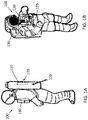
- FIGS. 1A and 1B show different aspects of an EMU 100 to which power is transferred wirelessly according to one or more embodiments.
- FIG. 1A shows a side view of the EMU 100.
- the EMU 100 is made up of several components such as a hard torso, arm and leg attachments, and a helmet.
- Systems that are affixed as part of the EMU 100 include a primary life support system (PLSS) 120 and a display and control module (DCM) 130. Together, the components of the EMU 100 create a habitable environment for a wearer performing extravehicular activity in space.
- PLSS primary life support system
- DCM display and control module
- an EMU power transfer unit 110 may be included in the PLSS 120 100 according to an exemplary embodiment.
- the EMU power transfer unit 110 includes a coil 105 that facilitates magnetic power transfer to the EMU 100 from a power transfer unit 210 ( FIG. 2 ).
- FIG. 1B shows an isometric view of the EMU 100.
- the DCM 130 is visible in the view shown in FIG. 1B .
- a coil 105 of the EMU power transfer unit 110 may be on an outer surface of the DCM 130 rather than on the outer surface of the PLSS 120 according to the exemplary embodiment shown in FIG. 1B .
- the EMU power transfer unit 110 may be within the DCM 130, for example.
- the locations of the EMU power transfer unit 110 and the coil 105 are not limited by the illustrated examples. As long as the coil 105 is exposed to facilitate wireless power transfer, other factors such as space, wiring density, and wire routing may drive the determination of where to locate the EMU power transfer unit 110 and the coil 105 within the EMU 100.
- the EMU power transfer unit 110 is further detailed with reference to FIG. 4 .
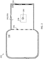
- FIG. 2 shows aspects of space habitat 200 that facilitates wireless power transfer to an EMU 100 according to one or more embodiments.
- the space habitat 200 may be a space vehicle, a space station, or a habitat on a planetary surface according to alternate embodiments.
- the space habitat 200 includes an airlock 220, which is a volume between an exterior hatch 230 leading to/from space or a planetary surface and an interior hatch 235 leading to/from an interior volume 240 of the space habitat 200.
- the airlock 220 may include a power transfer unit 210 with a coil 205 that facilitates wireless power transfer to an EMU.
- the power transfer unit 210 may be mounted to a structure 250 (e.g., wall 255) within the airlock 220, as shown, and is further discussed with reference to FIG. 4 .
- FIG. 3 shows a rover 300 that facilitates wireless power transfer to an EMU 100 according to one or more embodiments.
- the rover may include a seat 310 or other structure 250, as indicated.
- the rover 300 may include a power transfer unit 210 with a coil 205 in addition or alternately to the airlock 220.
- the seat 310 is shown as the exemplary structure 250 that includes the power transfer unit 210 and coil 205 in FIG. 3 , the example is not intended to limit the location of the power transfer unit 210 and coil 205 within the rover 300.
- FIG. 4 is a block diagram of a wireless power transfer system 400 that facilitates wireless power transfer to an EMU 100 according to one or more embodiments.
- the EMU power transfer unit 110 includes the coil 105 that is mounted on a surface of the EMU 100 as shown in FIG. 1B , for example.
- the EMU power transfer unit 110 also includes a power receiver 410.
- the coil 105 of the EMU 100 is magnetically coupled to the coil 205 of the power transfer unit 210, as shown.
- the resonant magnetic field generated by the coil 205 is converted to a current by the coil 105.
- the power receiver 410 may include a rectifier and other known components that convert an alternating current (AC) resonant magnetic field into a direct current (DC) voltage for use in the EMU 100.
- the power receiver 410 may include known components such as a resonant tank circuit, including the coil 105, and a high frequency rectifier.
- the power receiver 410 may be connected directly to an EMU battery 420 to charge the EMU battery 420 based on the power transfer from the power transfer unit 210 to the EMU power transfer unit 110.
- the EMU battery 420 may be connected to a power distribution module 430 that distributes power from the EMU battery 420 to various devices or loads in the EMU 100 (e.g., regulator, fans).
- an optional controller 415 may be included. The controller 415 may direct the DC voltage from the power receiver 410 to the EMU battery 420 for subsequent transfer to the power distribution module 430, as previously discussed. Under predefined conditions, the controller 415 may direct the DC voltage from the power receiver 410 directly to the power distribution module 430, bypassing charging of the EMU battery 420 according to this alternate embodiment.
- the power transfer unit 210 includes a power transmitter 440 that is coupled to the coil 205.
- the power transmitter 440 may be connected to a power bus of the space habitat 200 (e.g., space vehicle, space station, planetary habitat) or rover 300, for example.
- the power transmitter 440 may convert DC voltage from the space habitat 200 or rover 300 into an AC resonant magnetic field using known components such as an inverter and resonant tank circuit that includes the coil 205.
- the EMU power transfer unit 110 within the EMU 100 and the power transfer unit 210 that may be affixed to a structure 250 in an airlock 220 or on a rover 300 for example, an astronaut wearing the EMU 100 need not end the extravehicular activity and return to the interior volume 240 of a space habitat 200 when battery capacity is reaching exhaustion.
- the EMU battery 420 may have to be removed for charging according to prior approaches. This requires entering the interior volume 240 so that life support systems of the EMU 100 that require power may be shut down without endangering the astronaut. Because wireless charging does not require removal of the EMU battery 420 or shut down of the systems of the EMU 100, the charging or alternate power transfer may take place outside the interior volume 420 and extravehicular activity may be resumed with reduced interruption.
Landscapes
- Engineering & Computer Science (AREA)
- Power Engineering (AREA)
- Computer Networks & Wireless Communication (AREA)
- Remote Sensing (AREA)
- Aviation & Aerospace Engineering (AREA)
- Charge And Discharge Circuits For Batteries Or The Like (AREA)
Abstract
Description
- Exemplary embodiments pertain to the art of power management in space and, in particular, to wireless power transfer to an extravehicular mobility unit (EMU).
- In space applications, management of consumables (e.g., air, water) and power presents different challenges than in earth-based applications. When an astronaut is outside the space vehicle (i.e., performing extravehicular activity) on the surface of a planet or performing a spacewalk, for example, a depletion of any consumables or battery capacity may require termination of the extravehicular activity.
- In one embodiment, an extravehicular mobility unit (EMU) includes a resonant coil on a surface of the EMU to be coupled to a second resonant coil affixed to a structure via a resonant magnetic field and a receiver in the EMU coupled to the resonant coil to provide a direct current (DC) voltage based on the resonant magnetic field. A battery in the EMU is charged based on the DC voltage.
- Additionally or alternatively, in this or other embodiments, the EMU also includes a power distribution module coupled to the battery to distribute power to one or more systems in the EMU.
- Additionally or alternatively, in this or other embodiments, the one or more systems include a regulator and one or more fans.
- Additionally or alternatively, in this or other embodiments, the EMU also includes a controller connected to the receiver to direct the DC voltage from the receiver to the battery or to the power distribution module. The battery supplies the power distribution module based on the controller directing the DC voltage from the receiver to charge the battery.
- Additionally or alternatively, in this or other embodiments, the resonant coil is affixed on an outer surface of a primary life support system (PLSS) of the EMU.
- Additionally or alternatively, in this or other embodiments, the resonant coil is affixed on a surface of a display and control module (DCM) of the EMU.
- In another embodiment, a method of assembling an extravehicular mobility unit (EMU) includes affixing a resonant coil on a surface of the EMU, the resonant coil being coupled to a second resonant coil, which is affixed to a structure, via a resonant magnetic field. The method also includes coupling a receiver in the EMU to the resonant coil so that the receiver provides a direct current (DC) voltage based on the resonant magnetic field. A battery in the EMU is charged based on the DC voltage.
- Additionally or alternatively, in this or other embodiments, the method also includes coupling a power distribution module to the battery. The power distribution module distributes power based on the battery to one or more systems in the EMU.
- Additionally or alternatively, in this or other embodiments, the one or more systems include a regulator and one or more fans.
- Additionally or alternatively, in this or other embodiments, the method also includes arranging a controller to direct the DC voltage from the receiver to the battery or to the power distribution module. The battery supplies the power distribution module based on the controller directing the DC voltage from the receiver to charge the battery.
- Additionally or alternatively, in this or other embodiments, the method also includes affixing the resonant coil on an outer surface of a primary life support system (PLSS) of the EMU.
- Additionally or alternatively, in this or other embodiments, the method also includes affixing the resonant coil on an outer surface of a display and control module (DCM) of the EMU.
- In yet another embodiment, a system for power transfer in space includes a power transfer unit affixed to a structure. The power transfer unit includes a first resonant coil, a transmitter coupled to the first resonant coil, and an extravehicular mobility unit (EMU). The EMU includes a second resonant coil to be coupled to the first resonant coil via a resonant magnetic field, and a receiver coupled to the second resonant coil to provide a direct current (DC) voltage based on the resonant magnetic field. A battery in the EMU is charged based on the DC voltage.
- Additionally or alternatively, in this or other embodiments, the EMU further comprises a power distribution module coupled to the battery to distribute power to one or more systems of the EMU.
- Additionally or alternatively, in this or other embodiments, the one or more systems include a regulator and one or more fans.
- Additionally or alternatively, in this or other embodiments, the EMU further comprises a controller connected to the receiver to direct the DC voltage from the receiver to the battery or to the power distribution module. The battery supplies the power distribution module based on the controller directing the DC voltage from the receiver to charge the battery.
- Additionally or alternatively, in this or other embodiments, the structure is in an airlock of a space vehicle, a space station, or a planetary habitat.
- Additionally or alternatively, in this or other embodiments, the structure is part of a planetary rover.
- Additionally or alternatively, in this or other embodiments, the second resonant coil is on an outer surface of a primary life support system (PLSS) of the EMU
- Additionally or alternatively, in this or other embodiments, the second resonant coil is on an outer surface of a display and control module (DCM) of the EMU
- The following descriptions should not be considered limiting in any way. With reference to the accompanying drawings, like elements are numbered alike:
-
FIG. 1A shows a side view of an extravehicular mobility unit (EMU) to which power is wirelessly transferred according to one or more embodiments; -
FIG. 1B shows an isometric view of the EMU inFIG. 1A ; -
FIG. 2 shows aspects of space habitat that facilitates wireless power transfer to an EMU according to one or more embodiments; -
FIG. 3 shows a rover that facilitates wireless power transfer to an EMU according to one or more embodiments; and -
FIG. 4 is a block diagram of a system that facilitates wireless power transfer to an EMU according to one or more embodiments. - A detailed description of one or more embodiments of the disclosed apparatus and method are presented herein by way of exemplification and not limitation with reference to the Figures.
- As previously noted, in space applications, the duration of extravehicular activity may be limited by depletion of consumables or power. According to one prior approach, a battery in the EMU is removed and recharged. This requires that the astronaut wearing the EMU re-enter a space vehicle or habitat to have the life support functions that are provided by the EMU during extravehicular activity. According to another approach, the battery need not be removed but a physical connection must be made between a charger in the spacecraft and the EMU This requires a perfect electrical connection on all pins to operate. Embodiments of the systems and methods detailed herein relate to wireless power transfer to an EMU Power transfer to the EMU is facilitated via a resonant magnetic field. Thus, both a physical connection and removal of the battery are avoided.
-
FIGS. 1A and 1B show different aspects of an EMU 100 to which power is transferred wirelessly according to one or more embodiments.FIG. 1A shows a side view of the EMU 100. The EMU 100 is made up of several components such as a hard torso, arm and leg attachments, and a helmet. Systems that are affixed as part of the EMU 100 include a primary life support system (PLSS) 120 and a display and control module (DCM) 130. Together, the components of the EMU 100 create a habitable environment for a wearer performing extravehicular activity in space. As shown inFIG. 1A , an EMUpower transfer unit 110 may be included in the PLSS 120 100 according to an exemplary embodiment. The EMUpower transfer unit 110 includes acoil 105 that facilitates magnetic power transfer to the EMU 100 from a power transfer unit 210 (FIG. 2 ). -
FIG. 1B shows an isometric view of theEMU 100. TheDCM 130 is visible in the view shown inFIG. 1B . As indicated, acoil 105 of the EMUpower transfer unit 110 may be on an outer surface of theDCM 130 rather than on the outer surface of thePLSS 120 according to the exemplary embodiment shown inFIG. 1B . The EMUpower transfer unit 110 may be within theDCM 130, for example. The locations of the EMUpower transfer unit 110 and thecoil 105 are not limited by the illustrated examples. As long as thecoil 105 is exposed to facilitate wireless power transfer, other factors such as space, wiring density, and wire routing may drive the determination of where to locate the EMUpower transfer unit 110 and thecoil 105 within theEMU 100. The EMUpower transfer unit 110 is further detailed with reference toFIG. 4 . -
FIG. 2 shows aspects ofspace habitat 200 that facilitates wireless power transfer to anEMU 100 according to one or more embodiments. Thespace habitat 200 may be a space vehicle, a space station, or a habitat on a planetary surface according to alternate embodiments. In each embodiment, thespace habitat 200 includes anairlock 220, which is a volume between anexterior hatch 230 leading to/from space or a planetary surface and aninterior hatch 235 leading to/from aninterior volume 240 of thespace habitat 200. Theairlock 220 may include apower transfer unit 210 with acoil 205 that facilitates wireless power transfer to an EMU. Thepower transfer unit 210 may be mounted to a structure 250 (e.g., wall 255) within theairlock 220, as shown, and is further discussed with reference toFIG. 4 . -
FIG. 3 shows arover 300 that facilitates wireless power transfer to anEMU 100 according to one or more embodiments. The rover may include a seat 310 or other structure 250, as indicated. As the expanded front view of the back of the seat 310 shows, therover 300 may include apower transfer unit 210 with acoil 205 in addition or alternately to theairlock 220. While the seat 310 is shown as the exemplary structure 250 that includes thepower transfer unit 210 andcoil 205 inFIG. 3 , the example is not intended to limit the location of thepower transfer unit 210 andcoil 205 within therover 300. -
FIG. 4 is a block diagram of a wirelesspower transfer system 400 that facilitates wireless power transfer to anEMU 100 according to one or more embodiments. As shown, the EMUpower transfer unit 110 includes thecoil 105 that is mounted on a surface of theEMU 100 as shown inFIG. 1B , for example. The EMUpower transfer unit 110 also includes apower receiver 410. Thecoil 105 of theEMU 100 is magnetically coupled to thecoil 205 of thepower transfer unit 210, as shown. The resonant magnetic field generated by thecoil 205 is converted to a current by thecoil 105. Thepower receiver 410 may include a rectifier and other known components that convert an alternating current (AC) resonant magnetic field into a direct current (DC) voltage for use in theEMU 100. Thepower receiver 410 may include known components such as a resonant tank circuit, including thecoil 105, and a high frequency rectifier. - The
power receiver 410 may be connected directly to anEMU battery 420 to charge theEMU battery 420 based on the power transfer from thepower transfer unit 210 to the EMUpower transfer unit 110. As also indicated, theEMU battery 420 may be connected to apower distribution module 430 that distributes power from theEMU battery 420 to various devices or loads in the EMU 100 (e.g., regulator, fans). As shown inFIG. 4 , according to an alternate embodiment, anoptional controller 415 may be included. Thecontroller 415 may direct the DC voltage from thepower receiver 410 to theEMU battery 420 for subsequent transfer to thepower distribution module 430, as previously discussed. Under predefined conditions, thecontroller 415 may direct the DC voltage from thepower receiver 410 directly to thepower distribution module 430, bypassing charging of theEMU battery 420 according to this alternate embodiment. - The
power transfer unit 210 includes apower transmitter 440 that is coupled to thecoil 205. Thepower transmitter 440 may be connected to a power bus of the space habitat 200 (e.g., space vehicle, space station, planetary habitat) orrover 300, for example. Thepower transmitter 440 may convert DC voltage from thespace habitat 200 orrover 300 into an AC resonant magnetic field using known components such as an inverter and resonant tank circuit that includes thecoil 205. - Based on the wireless power transfer that is facilitated by the EMU
power transfer unit 110 within theEMU 100 and thepower transfer unit 210 that may be affixed to a structure 250 in anairlock 220 or on arover 300, for example, an astronaut wearing theEMU 100 need not end the extravehicular activity and return to theinterior volume 240 of aspace habitat 200 when battery capacity is reaching exhaustion. As previously noted, theEMU battery 420 may have to be removed for charging according to prior approaches. This requires entering theinterior volume 240 so that life support systems of theEMU 100 that require power may be shut down without endangering the astronaut. Because wireless charging does not require removal of theEMU battery 420 or shut down of the systems of theEMU 100, the charging or alternate power transfer may take place outside theinterior volume 420 and extravehicular activity may be resumed with reduced interruption. - The terminology used herein is for the purpose of describing particular embodiments only and is not intended to be limiting of the present disclosure. As used herein, the singular forms "a", "an" and "the" are intended to include the plural forms as well, unless the context clearly indicates otherwise. It will be further understood that the terms "comprises" and/or "comprising," when used in this specification, specify the presence of stated features, integers, steps, operations, elements, and/or components, but do not preclude the presence or addition of one or more other features, integers, steps, operations, element components, and/or groups thereof.
- While the present disclosure has been described with reference to an exemplary embodiment or embodiments, it will be understood by those skilled in the art that various changes may be made and equivalents may be substituted for elements thereof without departing from the scope of the present disclosure. In addition, many modifications may be made to adapt a particular situation or material to the teachings of the present disclosure without departing from the essential scope thereof. Therefore, it is intended that the present disclosure not be limited to the particular embodiment disclosed as the best mode contemplated for carrying out this present disclosure, but that the present disclosure will include all embodiments falling within the scope of the claims.
Claims (15)
- An extravehicular mobility unit, EMU (100), comprising:a resonant coil (105) on a surface of the EMU configured to be coupled to a second resonant coil (205) affixed to a structure via a resonant magnetic field;a receiver (410) in the EMU coupled to the resonant coil and configured to provide a direct current, DC, voltage based on the resonant magnetic field; anda battery (420) in the EMU configured to be charged based on the DC voltage.
- The EMU according to claim 1, further comprising a power distribution module (430) coupled to the battery and configured to distribute power to one or more systems in the EMU.
- The EMU according to claim 2, wherein the one or more systems include a regulator and one or more fans.
- The EMU according to claim 2 or 3, further comprising a controller (415) connected to the receiver and configured to direct the DC voltage from the receiver to the battery or to the power distribution module, wherein the battery is configured to supply the power distribution module based on the controller directing the DC voltage from the receiver to charge the battery.
- The EMU according to any preceding claim, wherein the resonant coil is affixed on an outer surface of a primary life support system, PLSS (120), of the EMU; or wherein the resonant coil is affixed on a surface of a display and control module, DCM (130), of the EMU.
- A method of assembling an extravehicular mobility unit, EMU (100), the method comprisingaffixing a resonant coil (105) on a surface of the EMU, the resonant coil being configured to be coupled to a second resonant coil (205), which is affixed to a structure, via a resonant magnetic field;coupling a receiver (410) in the EMU to the resonant coil and configuring the receiver to provide a direct current, DC, voltage based on the resonant magnetic field; andconfiguring a battery (420) in the EMU to be charged based on the DC voltage.
- The method according to claim 6, further comprising coupling a power distribution module (430) to the battery, wherein the power distribution module is configured to distribute power based on the battery to one or more systems in the EMU
- The method according to claim 7, wherein the one or more systems include a regulator and one or more fans.
- The method according to claim 7 or 8, further comprising arranging a controller (415) to direct the DC voltage from the receiver to the battery or to the power distribution module, wherein the battery is configured to supply the power distribution module based on the controller directing the DC voltage from the receiver to charge the battery.
- The method according to any of claims 6 to 9, further comprising affixing the resonant coil on an outer surface of a primary life support system, PLSS (120), of the EMU or affixing the resonant coil on an outer surface of a display and control module, DCM (130), of the EMU.
- A system for power transfer in space, the system comprising:
a power transfer unit (110) affixed to a structure, the power transfer unit comprising:a first resonant coil (205); anda transmitter (440) coupled to the first resonant coil (205); andthe extravehicular mobility unit (EMU) of any of claims 1 to 5, wherein the resonant coil of the EMU is configured to be coupled to the first resonant coil (205) via a resonant magnetic field. - The system according to claim 11, wherein the structure is in an airlock of a space vehicle, a space station, or a planetary habitat (200).
- The system according to claim 11 or 12, wherein the structure is part of a planetary rover (300).
- The system according to any of claims 11 to 13, wherein the second resonant coil is on an outer surface of a primary life support system, PLSS (120), of the EMU
- The system according to any of claims 11 to 13, wherein the second resonant coil is on an outer surface of a display and control module, DCM (130), of the EMU
Applications Claiming Priority (1)
| Application Number | Priority Date | Filing Date | Title |
|---|---|---|---|
| US17/322,284 US11611241B2 (en) | 2021-05-17 | 2021-05-17 | Wireless power transfer to an extravehicular mobility unit |
Publications (1)
| Publication Number | Publication Date |
|---|---|
| EP4092874A1 true EP4092874A1 (en) | 2022-11-23 |
Family
ID=81326095
Family Applications (1)
| Application Number | Title | Priority Date | Filing Date |
|---|---|---|---|
| EP22168508.4A Pending EP4092874A1 (en) | 2021-05-17 | 2022-04-14 | Wireless power transfer to an extravehicular mobility unit |
Country Status (4)
| Country | Link |
|---|---|
| US (1) | US11611241B2 (en) |
| EP (1) | EP4092874A1 (en) |
| JP (1) | JP7826104B2 (en) |
| CN (1) | CN115360832A (en) |
Citations (2)
| Publication number | Priority date | Publication date | Assignee | Title |
|---|---|---|---|---|
| US20130005251A1 (en) * | 2007-12-21 | 2013-01-03 | Cynetic Designs Ltd. | Vehicle seat inductive charger and data transmitter |
| US20170179750A1 (en) * | 2015-12-17 | 2017-06-22 | Motorola Solutions, Inc. | Method and device for wireless power transfer |
Family Cites Families (21)
| Publication number | Priority date | Publication date | Assignee | Title |
|---|---|---|---|---|
| US4842224A (en) * | 1987-10-20 | 1989-06-27 | The United States Of American As Represented By The Administrator, National Aeronautics And Space Administration | Suitport extra-vehicular access facility |
| JP2000198498A (en) | 1999-01-05 | 2000-07-18 | Nissan Motor Co Ltd | Space exploration vehicle |
| EP1891741A4 (en) * | 2005-06-08 | 2011-08-24 | Powercast Corp | ELECTRIC POWER SUPPLY OF A RADIO FREQUENCY ENERGY COLLECTION DEVICE |
| US8791600B2 (en) * | 2007-12-21 | 2014-07-29 | Roger J. Soar | Vehicle seat inductive charger and data transmitter |
| US20100090866A1 (en) * | 2008-10-13 | 2010-04-15 | Howard Chen | Optical Distress Beacon For Use In Space Environments |
| US20110278943A1 (en) | 2010-05-11 | 2011-11-17 | Searete Llc, A Limited Liability Corporation Of The State Of Delaware | System including wearable power receiver and wearable power-output device |
| US9870859B2 (en) * | 2012-07-15 | 2018-01-16 | Access Business Group International Llc | Variable mode wireless power supply systems |
| FR2995170B1 (en) * | 2012-08-28 | 2014-09-12 | Eblatas | ELECTRONIC DEVICE FOR DIVING EQUIPMENT. |
| CN103224038B (en) | 2013-03-01 | 2015-07-08 | 北京航空航天大学 | Two-round energy recovery system of extra vehicular activity space suit life support system |
| EP2994976B1 (en) | 2013-05-10 | 2018-07-11 | Cynetic Designs Ltd | Inductively coupled wireless power and data for a garment via a dongle |
| US11304500B2 (en) * | 2014-01-15 | 2022-04-19 | Lat Enterprises, Inc. | Wearable and replaceable pouch or skin for holding a portable battery pack |
| US9711994B2 (en) | 2014-01-31 | 2017-07-18 | Semiconductor Energy Laboratory Co., Ltd. | Electronic device and its operation system |
| US9500868B2 (en) * | 2014-07-10 | 2016-11-22 | Honeywell International Inc. | Space suit helmet display system |
| US9878787B2 (en) | 2015-07-15 | 2018-01-30 | Elwha Llc | System and method for operating unmanned aircraft |
| US10305296B2 (en) * | 2016-03-04 | 2019-05-28 | Hamilton Sundstrand Corporation | Intelligent battery self repair |
| US20170279292A1 (en) * | 2016-03-28 | 2017-09-28 | Intel Corporation | Multimode operation of wireless power system with single receiver |
| US10298060B2 (en) * | 2016-09-14 | 2019-05-21 | The United States Of America As Represented By The Administrator Of The National Aeronautics And Space Administration | Inductive power transfer for aerospace flight systems |
| US11760434B2 (en) * | 2019-01-07 | 2023-09-19 | Polaris Industries Inc. | Recreational vehicles with heated components |
| US20200326537A1 (en) * | 2019-04-11 | 2020-10-15 | Hypergiant Industries, Inc. | Gesture control of heads-up display |
| US20210250667A1 (en) * | 2020-02-06 | 2021-08-12 | Hamilton Sundstrand Corporation | Discrete spectral sensing for wireless, near-zero power health monitoring of a spacesuit hard upper torso |
| US20210351619A1 (en) * | 2020-05-06 | 2021-11-11 | Hamilton Sundstrand Corporation | Inductive power transfer in deep space and remote applications |
-
2021
- 2021-05-17 US US17/322,284 patent/US11611241B2/en active Active
-
2022
- 2022-04-14 EP EP22168508.4A patent/EP4092874A1/en active Pending
- 2022-04-19 CN CN202210411428.XA patent/CN115360832A/en active Pending
- 2022-04-21 JP JP2022069811A patent/JP7826104B2/en active Active
Patent Citations (2)
| Publication number | Priority date | Publication date | Assignee | Title |
|---|---|---|---|---|
| US20130005251A1 (en) * | 2007-12-21 | 2013-01-03 | Cynetic Designs Ltd. | Vehicle seat inductive charger and data transmitter |
| US20170179750A1 (en) * | 2015-12-17 | 2017-06-22 | Motorola Solutions, Inc. | Method and device for wireless power transfer |
Also Published As
| Publication number | Publication date |
|---|---|
| JP7826104B2 (en) | 2026-03-09 |
| JP2022176893A (en) | 2022-11-30 |
| CN115360832A (en) | 2022-11-18 |
| US11611241B2 (en) | 2023-03-21 |
| US20220368158A1 (en) | 2022-11-17 |
Similar Documents
| Publication | Publication Date | Title |
|---|---|---|
| US11967837B2 (en) | Bidirectional wireless power transfer with auxiliary devices | |
| US6489745B1 (en) | Contactless power supply | |
| JP6707611B2 (en) | Wireless charging device with built-in auxiliary power supply and auxiliary power supply | |
| JP6065838B2 (en) | Wireless power feeding system and wireless power feeding method | |
| EP2867978B1 (en) | Wireless energy transfer for rechargeable batteries | |
| US20040189246A1 (en) | System and method for inductive charging a wireless mouse | |
| KR20220030262A (en) | Modular Electric Battery-Powered Systems and Methods | |
| US20160294204A1 (en) | Adaptive battery pack | |
| US20140077758A1 (en) | Apparatus for inductive charging of portable devices in vehicles | |
| US7615900B1 (en) | Power generator for electronic devices | |
| WO2008072014A1 (en) | Battery charger | |
| CN109149684A (en) | a wireless charging device | |
| EP4092874A1 (en) | Wireless power transfer to an extravehicular mobility unit | |
| WO2019134736A1 (en) | Solar panel cleaning apparatus and method | |
| US6915145B2 (en) | Self-rechargeable portable telephone | |
| EP3907855B1 (en) | Inductive power transfer in deep space and remote applications | |
| US20250033493A1 (en) | Multi-output battery electric vehicle charger with switched mode power supply | |
| US20240204563A1 (en) | System and method to provide portable and continous power supply with re-charging feature | |
| KR20150132967A (en) | Bag having apparatus for charging auxiliary battery | |
| CN115923543A (en) | Energy transfer system and method including fully integrated supply device | |
| CN106253406A (en) | A kind of wireless charging terminal under water | |
| US20220149657A1 (en) | Power receiving device, movable unit, wireless power transmission system, and movable unit system | |
| CN201018297Y (en) | Field vehicle-mounted charging type portable B-ultrasonic machine uninterruptible power supply apparatus | |
| JP3248909U (en) | Digital signage with battery | |
| US20240006921A1 (en) | Power supply mat, power supply vehicle, and noncontact power supply system |
Legal Events
| Date | Code | Title | Description |
|---|---|---|---|
| PUAI | Public reference made under article 153(3) epc to a published international application that has entered the european phase |
Free format text: ORIGINAL CODE: 0009012 |
|
| STAA | Information on the status of an ep patent application or granted ep patent |
Free format text: STATUS: THE APPLICATION HAS BEEN PUBLISHED |
|
| AK | Designated contracting states |
Kind code of ref document: A1 Designated state(s): AL AT BE BG CH CY CZ DE DK EE ES FI FR GB GR HR HU IE IS IT LI LT LU LV MC MK MT NL NO PL PT RO RS SE SI SK SM TR |
|
| STAA | Information on the status of an ep patent application or granted ep patent |
Free format text: STATUS: REQUEST FOR EXAMINATION WAS MADE |
|
| 17P | Request for examination filed |
Effective date: 20230516 |
|
| RBV | Designated contracting states (corrected) |
Designated state(s): AL AT BE BG CH CY CZ DE DK EE ES FI FR GB GR HR HU IE IS IT LI LT LU LV MC MK MT NL NO PL PT RO RS SE SI SK SM TR |
|
| STAA | Information on the status of an ep patent application or granted ep patent |
Free format text: STATUS: EXAMINATION IS IN PROGRESS |
|
| 17Q | First examination report despatched |
Effective date: 20240711 |