EP4092841A1 - Plug connector and connector set with a lever extension - Google Patents
Plug connector and connector set with a lever extension Download PDFInfo
- Publication number
- EP4092841A1 EP4092841A1 EP22173953.5A EP22173953A EP4092841A1 EP 4092841 A1 EP4092841 A1 EP 4092841A1 EP 22173953 A EP22173953 A EP 22173953A EP 4092841 A1 EP4092841 A1 EP 4092841A1
- Authority
- EP
- European Patent Office
- Prior art keywords
- lever
- connector
- extension
- plug
- plug connector
- Prior art date
- Legal status (The legal status is an assumption and is not a legal conclusion. Google has not performed a legal analysis and makes no representation as to the accuracy of the status listed.)
- Pending
Links
Images



Classifications
-
- H—ELECTRICITY
- H01—ELECTRIC ELEMENTS
- H01R—ELECTRICALLY-CONDUCTIVE CONNECTIONS; STRUCTURAL ASSOCIATIONS OF A PLURALITY OF MUTUALLY-INSULATED ELECTRICAL CONNECTING ELEMENTS; COUPLING DEVICES; CURRENT COLLECTORS
- H01R13/00—Details of coupling devices of the kinds covered by groups H01R12/70 or H01R24/00 - H01R33/00
- H01R13/46—Bases; Cases
- H01R13/502—Bases; Cases composed of different pieces
-
- H—ELECTRICITY
- H01—ELECTRIC ELEMENTS
- H01R—ELECTRICALLY-CONDUCTIVE CONNECTIONS; STRUCTURAL ASSOCIATIONS OF A PLURALITY OF MUTUALLY-INSULATED ELECTRICAL CONNECTING ELEMENTS; COUPLING DEVICES; CURRENT COLLECTORS
- H01R13/00—Details of coupling devices of the kinds covered by groups H01R12/70 or H01R24/00 - H01R33/00
- H01R13/62—Means for facilitating engagement or disengagement of coupling parts or for holding them in engagement
- H01R13/629—Additional means for facilitating engagement or disengagement of coupling parts, e.g. aligning or guiding means, levers, gas pressure electrical locking indicators, manufacturing tolerances
- H01R13/62933—Comprising exclusively pivoting lever
- H01R13/62955—Pivoting lever comprising supplementary/additional locking means
-
- H—ELECTRICITY
- H01—ELECTRIC ELEMENTS
- H01R—ELECTRICALLY-CONDUCTIVE CONNECTIONS; STRUCTURAL ASSOCIATIONS OF A PLURALITY OF MUTUALLY-INSULATED ELECTRICAL CONNECTING ELEMENTS; COUPLING DEVICES; CURRENT COLLECTORS
- H01R13/00—Details of coupling devices of the kinds covered by groups H01R12/70 or H01R24/00 - H01R33/00
- H01R13/62—Means for facilitating engagement or disengagement of coupling parts or for holding them in engagement
- H01R13/639—Additional means for holding or locking coupling parts together, after engagement, e.g. separate keylock, retainer strap
-
- H—ELECTRICITY
- H01—ELECTRIC ELEMENTS
- H01R—ELECTRICALLY-CONDUCTIVE CONNECTIONS; STRUCTURAL ASSOCIATIONS OF A PLURALITY OF MUTUALLY-INSULATED ELECTRICAL CONNECTING ELEMENTS; COUPLING DEVICES; CURRENT COLLECTORS
- H01R13/00—Details of coupling devices of the kinds covered by groups H01R12/70 or H01R24/00 - H01R33/00
- H01R13/62—Means for facilitating engagement or disengagement of coupling parts or for holding them in engagement
- H01R13/629—Additional means for facilitating engagement or disengagement of coupling parts, e.g. aligning or guiding means, levers, gas pressure electrical locking indicators, manufacturing tolerances
-
- H—ELECTRICITY
- H01—ELECTRIC ELEMENTS
- H01R—ELECTRICALLY-CONDUCTIVE CONNECTIONS; STRUCTURAL ASSOCIATIONS OF A PLURALITY OF MUTUALLY-INSULATED ELECTRICAL CONNECTING ELEMENTS; COUPLING DEVICES; CURRENT COLLECTORS
- H01R13/00—Details of coupling devices of the kinds covered by groups H01R12/70 or H01R24/00 - H01R33/00
- H01R13/62—Means for facilitating engagement or disengagement of coupling parts or for holding them in engagement
- H01R13/629—Additional means for facilitating engagement or disengagement of coupling parts, e.g. aligning or guiding means, levers, gas pressure electrical locking indicators, manufacturing tolerances
- H01R13/62933—Comprising exclusively pivoting lever
-
- H—ELECTRICITY
- H01—ELECTRIC ELEMENTS
- H01R—ELECTRICALLY-CONDUCTIVE CONNECTIONS; STRUCTURAL ASSOCIATIONS OF A PLURALITY OF MUTUALLY-INSULATED ELECTRICAL CONNECTING ELEMENTS; COUPLING DEVICES; CURRENT COLLECTORS
- H01R13/00—Details of coupling devices of the kinds covered by groups H01R12/70 or H01R24/00 - H01R33/00
- H01R13/62—Means for facilitating engagement or disengagement of coupling parts or for holding them in engagement
- H01R13/629—Additional means for facilitating engagement or disengagement of coupling parts, e.g. aligning or guiding means, levers, gas pressure electrical locking indicators, manufacturing tolerances
- H01R13/62933—Comprising exclusively pivoting lever
- H01R13/62961—Pivoting lever having extendable handle
-
- H—ELECTRICITY
- H01—ELECTRIC ELEMENTS
- H01R—ELECTRICALLY-CONDUCTIVE CONNECTIONS; STRUCTURAL ASSOCIATIONS OF A PLURALITY OF MUTUALLY-INSULATED ELECTRICAL CONNECTING ELEMENTS; COUPLING DEVICES; CURRENT COLLECTORS
- H01R13/00—Details of coupling devices of the kinds covered by groups H01R12/70 or H01R24/00 - H01R33/00
- H01R13/62—Means for facilitating engagement or disengagement of coupling parts or for holding them in engagement
- H01R13/629—Additional means for facilitating engagement or disengagement of coupling parts, e.g. aligning or guiding means, levers, gas pressure electrical locking indicators, manufacturing tolerances
- H01R13/62933—Comprising exclusively pivoting lever
- H01R13/62944—Pivoting lever comprising gear teeth
Definitions
- the present invention relates to a plug connector for plugging together with a counter connector, and to a connector set.
- Plug connectors and connector sets are known from prior art, and different demands are made on them.
- these plug connectors (the same applies to the connector sets which are not always explicitly mentioned hereinafter) receive a number of plug contacts that increases by tendency, whereby the forces to be spent for plugging together the plug connector and the counter connector increase. Simultaneously, a reduction in size of the plug connector is strived for.
- the plug connectors and connector sets from prior art can include a lever.
- the force required for plugging together can thus be applied by the user via the lever.
- the lever can increase the size of the plug connector.
- the plug connector comprises a connector housing and a lever device with a lever that is movable from a plug position into a securing position and with a coupling member that is movable by the lever and that may be engaged with the counter connector, wherein a lever extension is attached to the lever, the lever extension being extendable and/or retractable with respect to the lever, wherein in a securing position of the lever, a swivel movement of the lever out of the securing position is blocked by the retracted lever extension, and wherein the connector housing comprises a guiding member, by which a shifting-in of the lever extension is blocked if the lever is moved out of the plug position and is not in the securing position.
- This object is furthermore achieved by the invention for the connector set mentioned in the beginning in that it comprises a plug connector according to the invention and a counter connector with coupling elements which can be engaged with the coupling of the plug connector.
- the plug connector according to the invention and the connector set according to the invention have the advantage that by the lever extension, the force a user has to spend for plugging together can be reduced, wherein the plug connector or the connector set, respectively, do not increase the structural size of the plug connector in a retracted state.
- the plug connector according to the invention and the connector set according to the invention thus have an improved operability with a reduced size.
- the plug connector and the connector set can be further improved by the following embodiments described more in detail. Additional technical features of these embodiments can be arbitrarily combined or else omitted if the technical effect provided by the omitted technical feature is not relevant.
- the coupling of the plug connector can be formed by a gearwheel or individual teeth of such a gearwheel. Equally, the coupling can be formed by one single tooth, beam or the like extending away from the axis of rotation.
- the guiding member represents a limit stop for the lever extension which prevents the lever extension from being retracted.
- the lever extension can block a swivel movement of the lever out of this securing position either directly or indirectly.
- the lever extension can in particular be part of the lever device.
- the guiding member can be designed as a restraint guiding by which the lever extension is shifted with respect to the lever along a swivel movement.
- the position of the lever extension compared to the lever i. e. whether and to what extent it is retracted or extended, can thus not be freely adjusted by the user but is predetermined by the guiding member. An operating error originating from the lever extension is thus nearly excluded.
- the plug connector according to the invention can be further improved by the guiding member comprising at least one link at the connector housing in which the lever extension is guided.
- the connector housing can include two symmetrically arranged links. These can be preferably arranged oppositely at the connector housing and each be accessible along a direction parallel to the axis of rotation of the lever device.
- a cross-section of the link can be semicircular or rectangular, the link being preferably designed complimentarily to a guiding element, for example a guiding pin, which can be provided at the lever extension and is guided in the link.
- the guiding member can also be a sliding path or sliding surface formed at the outer side of the connector housing.
- a pocket in which the lever extension is received in its retracted state can be provided at the connector housing.
- the pocket can be a radial pocket.
- a pocket is to be understood as a recess in the connector housing. In a radial pocket, this recess extends in the radial direction, preferably away from the axis of rotation.
- the pocket can preferably be rectangular or cuboid.
- two symmetric pockets are provided at the connector housing.
- the pockets can be arranged both symmetrically in themselves and symmetrically with respect to each other.
- the pocket can conically expand away from the axis of rotation of the lever device, or taper towards the axis of rotation, respectively.
- the guiding member can end in the pocket.
- the guiding member can be interrupted, and the pocket can follow the interruption. In other words, the guiding member can pass over into the pocket.
- the pocket can thus be formed by an extension of the link, where this extension can extend substantially perpendicularly to the original direction of the link.
- the link can also end in the pocket.
- the lever extension In the securing position, the lever extension can be insertable into the pocket.
- the insertion is effected by shifting-in and in particular blocking the lever.
- the swivel movement of the lever device can be blocked in a positively engaging manner. Consequently, it is advantageous for the lever extension to be formed complementarily to the pocket at least in sections.
- the pushing-in of the lever extension into the pocket is effected along a direction perpendicular to the swivel movement. Walls of the pocket extending in the radial direction can thus serve as a limit stop for sections of the lever extension.
- These sections of the lever extension can also be referred to as arms or legs of the lever extension.
- the arms or legs of the lever extension are received in the pocket or the pockets with a slight clearance.
- Both the lever and the lever extension preferably have an approximately U-shaped design.
- the lever can be held at the free ends of its shape at the connector housing in a swiveling manner.
- the lever extension also preferably has a U-shaped design, but it is held at the lever in a swiveling manner.
- the lever and the lever extension can embody the lever device wherein further elements can be provided.
- the lever extension can have two legs and the connector housing two opposed pockets, wherein the legs of the lever extension can be insertable into the pockets in the securing position.
- the retracted lever extension does not project over the lever.
- the lever extension thus permits, in its extended state by a longer mechanical lever, to generate a higher plug force with the same operating force, i. e. the force spent by the user, than without the lever extension.
- the structural size of the plug connector can be reduced by retracting the lever extension.
- the lever extension can be located completely within the cubature of the lever.
- the lever can have a mounting for the lever extension accessible through a mounting opening and substantially completely enclose the lever extension.
- a stroke by which the lever extension is extended with respect to the lever can depend on an angular position of the lever device.
- the lever extension can have a maximum stroke which results from the change of the length of the lever device between the retracted state and the extended state of the lever extension.
- the lever extension is extended by the maximum stroke, the highest plug force can be reached.
- the stroke by which the lever extension is extended with respect to the lever can thus be advantageous for the stroke by which the lever extension is extended with respect to the lever to increase as the lever device is transferred from the plug position towards the securing position.
- a restraint guiding of the lever extension by the guiding member designed in this manner has the advantage that the required length of the lever device can be individually adapted to the plug connector used.
- a lower plug force is required than in a second phase.
- the connector housing is plugged together with a counter connector housing which requires less force than the plugging together of a plurality of electric contacts in the second phase.
- the increase of the stroke can be linear or nonlinear, depending on the angle of rotation of the lever device. Equally, a two-stage increase of the length of the mechanical lever (which is achieved by extending the lever extension) is possible, for example in a case where a first set of contact elements is to contact the corresponding counter contact elements before a second set of contact elements is contacted.
- the lever extension can be held at the lever to be linearly shiftable towards an axis of rotation.
- the lever extension is shiftable in the securing position of the lever device. This has the advantage that in an orderly performed swivel movement of the lever, no component of the force performing the swivel movement actuates the lever extension, i. e. shifts the latter with respect to the lever towards the axis of rotation or away from it. The swivel movement of the lever device is thus completely independent of the linear movement of the lever extension while it is being retracted or extended.
- the lever extension can have a loss prevention device by which the lever extension can be captively held at the lever.
- the loss prevention device can be embodied to be releasable so that the lever extension can be removed from the lever.
- the loss prevention device can comprise several latching stages to latch the lever extension, for example, in a retracted state. This has the advantage that the lever extension is secured in its retracted state and cannot release itself from it, i. e. not without the action of a force by the user.
- the lever extension can provide a lever restraint for the relevant positions, such as the retracted state and the extended state, which restrains the movement between the lever and the lever extension, wherein a predetermined force is sufficient to release the lever restraint.
- the loss prevention device can be a lever latching edge which stops against a further edge of the lever, wherein this latching can preferably be only releasable upon the actuation of a release element.
- the connector housing can include a restraining or latching element by which a swivel movement of the lever in the securing position out of the securing position is restrained or blocked.
- the lever and/or the lever extension was preferably assumed. Nevertheless, other shapes of these two elements are also conceivable.
- the lever could have the shape of a W, or more general, the shape of a comb, wherein such a lever can be fastened to the axis of rotation by means of each one of its teeth.
- the lever extension can also have a corresponding shape.
- the plug connector can also have more than one link according to the invention, wherein maximally only two can be provided at the side faces, and further links can be formed in the connector housing.
- the connector set according to the invention can comprise any embodiment of the above described plug connector.
- the lever extension of the plug connector can preferably be a housing retention which can only be transferred to its retracted state with a correct plug connection between the plug connector and the counter connector.
- Such a lever extension can thus represent a CPA (contact positioning assurance).
- FIG. 1 a connector set 1 with a plug connector 3 from prior art is described.
- the connector set 1 according to the invention or the plug connector 3 according to the invention of the following Figures 3 to 11 can also include basic elements of this connector set 1 or plug connector 3 from prior art.
- a repeating description of technical features is therefore largely omitted in the drawings. If technical features in different drawings differ from each other as to their functions, this is explicitly described.
- a connector set 1 from prior art is shown, the connector set 1 comprising a plug connector 3 and a counter connector 5.
- a lever 7 is held at a connector housing 11 of the plug connector 3 to be rotating about an axis of rotation 9.
- the lever 7 has a U-shaped design and includes two lever arms 7a which partially grip around the connector housing 11.
- the lever 7 is integrally formed in the shown embodiment and can also be referred to as lever device 13.
- a coupling 15 is furthermore provided near the axis of rotation 9 which can be caused to engage with corresponding elements of the counter connector 5 and thus permit a facilitated plugging together of the plug connector 3 with the counter connector 5.
- the lever 7 has a lever length L.
- the latter is measured from one end 17 of the lever 7 to the axis of rotation 9.
- the lever length L corresponds to the length of a lever arm as it is used for the calculation by the lever principle.
- the lever 7 can, for example, collide in the region of feed cables 19 with them and aggravate handling.
- the required lever length L leads to a projection 21a beyond the connector housing 11 which enlarges the required installation volume of the shown connector set 1.
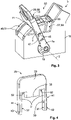
- a plug connector 3 according to the invention is shown which can, for example, also be plugged together with the counter connector 5 shown in Fig. 1 and Fig. 2 (cf. Figs. 13 and 14 ).
- the plug connector 3 includes a lever device 13 which comprises the lever 7 and a lever extension 29 attached to the lever 7 which can be extended and/or retracted with respect to the lever 7.
- the lever extension 29 can also be U-shaped.
- the lever extension 29 is separately shown in Fig. 4 .
- the lever extension 29 includes two arms 31 and one basis 33.
- the basis 33 also includes a latching region 35.
- the embodiment of the lever extension 29 shown in Fig. 4 includes a guiding pin 39 on the inner side 37 of the arms 31.
- latching elements 43 are provided on an outer side 41 of the arms 31. They have a semicircular cross-section only by way of example. Other cross-sections of the latching elements 43, for example in the form of a pyramid or a sawtooth (both not shown), are also conceivable.
- lever extension 29 received in the lever 7 of the plug connector 3 of Fig. 3 corresponds to that of Fig. 4 , however, without the guiding pin 39. To differentiate between them, this lever extension of the first embodiment is designated with reference numeral 29a.
- the lever extension 29 of Fig. 4 corresponds to the lever extension of the second embodiment which is designated with reference numeral 29b.
- the latching elements 43 represent a loss prevention device 47 in connection with openings 45 in the lever arm 7a by which the lever extension 29 is captively held at the lever 7.
- the lever extension 29 is shiftably held at the lever 7 linearly radially towards the axis of rotation 9 of the lever device 13.
- the connector housing 11 includes two guiding members 49 which are embodied as sliding surface 51.
- This guiding member 49 takes care that, when the lever 7 is moved out of the plug position 23 and is not in the securing position 25, a shifting of the lever extension 29 into the lever 7 is blocked. This is done by means of two support surfaces 52 which are indicated in Fig. 4 .
- the guiding member 49 is interrupted in an upper region 53 of the connector housing 11.
- a pocket 57 follows this interruption 55.
- a pocket can be understood as a recess in the connector housing.
- the guiding member 49 ends in the pocket 57 by means of or at the interruption 55.
- the pocket 57 can in particular be a radial pocket 58.
- lever extension 29 is in the extended state 59 and projects beyond the lever 7.
- the plug connector 3 according to the invention is shown in a side view, wherein the lever arrangement 29 is cut in the region of a sidewall of the connector housing 11.
- the connector housing 11 is not cut, but the lever 7 and the lever extension 29 are.
- the axis of rotation 9 is not shown in all figures.
- This retracted state 61 of the lever extension 29 is also shown in the perspective representation of the plug connector 3 according to the invention of Fig. 8 .
- the lever 7 is drawn in a semi-transparent manner for illustration purposes.
- the lever is in its securing position 25.
- the connector housing 11 also includes a restraining or latching element 69.
- the latter blocks the lever 7 at a latching tongue 71 which is also shown in Fig. 3 .
- the positive engagement 65 between the latching tongue 71 and the restraining or latching element 69 prevents the swivel movement 63.
- the guiding member 49 comprises a link 73.
- a guiding pin 39 (cf. Fig. 4 ) is guided.
- two guiding pins 39 are provided, one on each side of the connector housing 11.
- Fig. 9 the lever extension 29 is received in the lever 7 in its retracted state 61, the lever being in the plug position 23.
- the link 73 represents a restraint guiding 75. By this restraint guiding 75, a stroke 77 by which the lever extension 29 is extended with respect to the lever 7 depends on an angular position 79 of the lever device 13.
- the angular position 79 of the lever device 13 can vary between the plug position 23 ( Fig. 9 ) and the securing position 25 ( Figs. 11 and 12 ).
- a schematic dependence of the stroke 77 on the angular position 79 is shown in a diagram 81 not drawn to scale in Fig. 9 .
- the stroke 77 increases to a maximum value (marked by "max") and remains at this maximum value until the securing position 25 is reached.
- the lever extension 29 can be retracted into the pocket 57, in the securing position 25, both a stroke 77 of 0 (as is shown in Fig. 9 ) and a maximum stroke 77 are possible.
- the latter marks the extended state 59 of the lever extension 29.
- lever arrangement 13 or the lever 7, respectively reaches the securing position 25, wherein the lever extension 29 is still in its extended state 59. This is shown in Fig. 11 . In this position, the guiding pin 39, however, is no longer blocked by the link 73 since the latter is interrupted at the pocket 57.
- the interruption 55 permits to transfer the lever extension 29 to the retracted state 61, wherein at least some sections of the lever extension 29 are here received in the pocket 57.
- a positive engagement 65 between the pocket 57 and the lever extension 29 in its retracted state 61 which blocks a swivel movement 63 is created.
- the embodiment of the link 73 shown in Figs. 10 to 12 differs from the link 73 of Fig. 9 .
- the link 73 of Fig. 9 is schematically shown in a dotted line and designated with reference numeral 73a.
- Figs. 13 and 14 the two exemplary embodiments of the plug connector 3 according to the invention are shown in a corresponding connector set 1 according to the invention. These figures are to illustrate the advantages over the solutions from prior art which are shown in Figs. 1 and 2 .
- the connector set 1 according to the invention does not contact the feed cables 19 which increases operability.
- FIG. 14 A further advantage of the connector set 1 according to the invention is shown in Fig. 14 in which the lever 7 is in its securing position 25, and the lever extension 29 (concealed by the lever 7) is in its retracted state 61.
- a projection 21b that can be achieved with the solution according to the invention is clearly smaller than the projection 21 a of the solution from prior art ( Fig. 2 ), so that a smaller installation space is required.
Landscapes
- Details Of Connecting Devices For Male And Female Coupling (AREA)
Abstract
Description
- The present invention relates to a plug connector for plugging together with a counter connector, and to a connector set.
- Plug connectors and connector sets are known from prior art, and different demands are made on them. For example, these plug connectors (the same applies to the connector sets which are not always explicitly mentioned hereinafter) receive a number of plug contacts that increases by tendency, whereby the forces to be spent for plugging together the plug connector and the counter connector increase. Simultaneously, a reduction in size of the plug connector is strived for.
- To overcome the plug forces, the plug connectors and connector sets from prior art can include a lever. The force required for plugging together can thus be applied by the user via the lever. However, the lever can increase the size of the plug connector.
- It is thus the object of the present invention to provide a plug connector or connector set, respectively, which meets the demands both on the plug force and a maximum size.
- The present invention achieves this object for the plug connector mentioned in the beginning in that the plug connector comprises a connector housing and a lever device with a lever that is movable from a plug position into a securing position and with a coupling member that is movable by the lever and that may be engaged with the counter connector, wherein a lever extension is attached to the lever, the lever extension being extendable and/or retractable with respect to the lever, wherein in a securing position of the lever, a swivel movement of the lever out of the securing position is blocked by the retracted lever extension, and wherein the connector housing comprises a guiding member, by which a shifting-in of the lever extension is blocked if the lever is moved out of the plug position and is not in the securing position.
- This object is furthermore achieved by the invention for the connector set mentioned in the beginning in that it comprises a plug connector according to the invention and a counter connector with coupling elements which can be engaged with the coupling of the plug connector.
- The plug connector according to the invention and the connector set according to the invention have the advantage that by the lever extension, the force a user has to spend for plugging together can be reduced, wherein the plug connector or the connector set, respectively, do not increase the structural size of the plug connector in a retracted state. The plug connector according to the invention and the connector set according to the invention thus have an improved operability with a reduced size.
- The plug connector and the connector set can be further improved by the following embodiments described more in detail. Additional technical features of these embodiments can be arbitrarily combined or else omitted if the technical effect provided by the omitted technical feature is not relevant.
- The coupling of the plug connector can be formed by a gearwheel or individual teeth of such a gearwheel. Equally, the coupling can be formed by one single tooth, beam or the like extending away from the axis of rotation.
- If the lever is neither in the plug position nor in the securing position, the guiding member represents a limit stop for the lever extension which prevents the lever extension from being retracted.
- If the lever is in the securing position and the lever extension retracted, the lever extension can block a swivel movement of the lever out of this securing position either directly or indirectly. The lever extension can in particular be part of the lever device.
- In a further advantageous embodiment of the plug connector according to the invention, the guiding member can be designed as a restraint guiding by which the lever extension is shifted with respect to the lever along a swivel movement. The position of the lever extension compared to the lever, i. e. whether and to what extent it is retracted or extended, can thus not be freely adjusted by the user but is predetermined by the guiding member. An operating error originating from the lever extension is thus nearly excluded.
- The plug connector according to the invention can be further improved by the guiding member comprising at least one link at the connector housing in which the lever extension is guided. In particular, the connector housing can include two symmetrically arranged links. These can be preferably arranged oppositely at the connector housing and each be accessible along a direction parallel to the axis of rotation of the lever device. A cross-section of the link can be semicircular or rectangular, the link being preferably designed complimentarily to a guiding element, for example a guiding pin, which can be provided at the lever extension and is guided in the link.
- The guiding member can also be a sliding path or sliding surface formed at the outer side of the connector housing.
- In a further advantageous embodiment, a pocket in which the lever extension is received in its retracted state can be provided at the connector housing. The pocket can be a radial pocket. A pocket is to be understood as a recess in the connector housing. In a radial pocket, this recess extends in the radial direction, preferably away from the axis of rotation. The pocket can preferably be rectangular or cuboid. Preferably, two symmetric pockets are provided at the connector housing. The pockets can be arranged both symmetrically in themselves and symmetrically with respect to each other. The pocket can conically expand away from the axis of rotation of the lever device, or taper towards the axis of rotation, respectively.
- The guiding member can end in the pocket. The guiding member can be interrupted, and the pocket can follow the interruption. In other words, the guiding member can pass over into the pocket. In case of a link, the pocket can thus be formed by an extension of the link, where this extension can extend substantially perpendicularly to the original direction of the link. The link can also end in the pocket.
- In the securing position, the lever extension can be insertable into the pocket. Preferably, the insertion is effected by shifting-in and in particular blocking the lever.
- With the lever extension being retracted or shifted in the pocket, preferably the pockets, the swivel movement of the lever device can be blocked in a positively engaging manner. Consequently, it is advantageous for the lever extension to be formed complementarily to the pocket at least in sections. The pushing-in of the lever extension into the pocket is effected along a direction perpendicular to the swivel movement. Walls of the pocket extending in the radial direction can thus serve as a limit stop for sections of the lever extension. These sections of the lever extension can also be referred to as arms or legs of the lever extension. Preferably, the arms or legs of the lever extension are received in the pocket or the pockets with a slight clearance.
- Both the lever and the lever extension preferably have an approximately U-shaped design. The lever can be held at the free ends of its shape at the connector housing in a swiveling manner. The lever extension also preferably has a U-shaped design, but it is held at the lever in a swiveling manner. The lever and the lever extension can embody the lever device wherein further elements can be provided.
- In particular, the lever extension can have two legs and the connector housing two opposed pockets, wherein the legs of the lever extension can be insertable into the pockets in the securing position.
- According to the invention, it can be in particular advantageous if the retracted lever extension does not project over the lever. The lever extension thus permits, in its extended state by a longer mechanical lever, to generate a higher plug force with the same operating force, i. e. the force spent by the user, than without the lever extension. Simultaneously, the structural size of the plug connector can be reduced by retracting the lever extension. Preferably, the lever extension can be located completely within the cubature of the lever. Correspondingly, the lever can have a mounting for the lever extension accessible through a mounting opening and substantially completely enclose the lever extension.
- In a further advantageous embodiment, a stroke by which the lever extension is extended with respect to the lever can depend on an angular position of the lever device. With such an unambiguous association between the angular position of the lever device and the stroke by which the lever extension is extended, a variable plug force adapted to the plug connector's geometry and the plug connector's type can be generated depending on the angular position of the lever device at a constant force which is transferred by the user to the lever device.
- In the plug connector according to the invention, the lever extension can have a maximum stroke which results from the change of the length of the lever device between the retracted state and the extended state of the lever extension. When the lever extension is extended by the maximum stroke, the highest plug force can be reached.
- In one embodiment of the plug connector according to the invention, it can thus be advantageous for the stroke by which the lever extension is extended with respect to the lever to increase as the lever device is transferred from the plug position towards the securing position. A restraint guiding of the lever extension by the guiding member designed in this manner has the advantage that the required length of the lever device can be individually adapted to the plug connector used.
- Thus, merely by way of example, in a first phase of the plugging together of a plug connector with a counter connector, a lower plug force is required than in a second phase. In the first phase, the connector housing is plugged together with a counter connector housing which requires less force than the plugging together of a plurality of electric contacts in the second phase. To be able to spend the increasing required force with a constant force by the user, by the restraint guiding of the lever extension, the latter is extended whereby the mechanical lever is extended and a higher plug force is permitted.
- The increase of the stroke can be linear or nonlinear, depending on the angle of rotation of the lever device. Equally, a two-stage increase of the length of the mechanical lever (which is achieved by extending the lever extension) is possible, for example in a case where a first set of contact elements is to contact the corresponding counter contact elements before a second set of contact elements is contacted.
- Preferably, the lever extension can be held at the lever to be linearly shiftable towards an axis of rotation. In a particularly preferred manner, the lever extension is shiftable in the securing position of the lever device. This has the advantage that in an orderly performed swivel movement of the lever, no component of the force performing the swivel movement actuates the lever extension, i. e. shifts the latter with respect to the lever towards the axis of rotation or away from it. The swivel movement of the lever device is thus completely independent of the linear movement of the lever extension while it is being retracted or extended.
- In a further embodiment, the lever extension can have a loss prevention device by which the lever extension can be captively held at the lever. Thus, an unintentional loss of the lever extension can be prevented. The loss prevention device can be embodied to be releasable so that the lever extension can be removed from the lever. Furthermore, the loss prevention device can comprise several latching stages to latch the lever extension, for example, in a retracted state. This has the advantage that the lever extension is secured in its retracted state and cannot release itself from it, i. e. not without the action of a force by the user.
- The lever extension can provide a lever restraint for the relevant positions, such as the retracted state and the extended state, which restrains the movement between the lever and the lever extension, wherein a predetermined force is sufficient to release the lever restraint. In contrast, the loss prevention device can be a lever latching edge which stops against a further edge of the lever, wherein this latching can preferably be only releasable upon the actuation of a release element.
- In a further advantageous embodiment, the connector housing can include a restraining or latching element by which a swivel movement of the lever in the securing position out of the securing position is restrained or blocked.
- This has the advantage that the lever is, after it has reached the securing position, temporarily secured in this position even if the lever extension is not yet in its retracted state. The restraining or latching element of the connector housing thus secures the lever device in the securing position and can be understood as a primary retention, whereas the retracted lever extension can be understood as a secondary retention.
- In the above embodiments, a U-shape of the lever and/or the lever extension was preferably assumed. Nevertheless, other shapes of these two elements are also conceivable. For example, the lever could have the shape of a W, or more general, the shape of a comb, wherein such a lever can be fastened to the axis of rotation by means of each one of its teeth. The lever extension can also have a corresponding shape. Correspondingly, the plug connector can also have more than one link according to the invention, wherein maximally only two can be provided at the side faces, and further links can be formed in the connector housing.
- The connector set according to the invention can comprise any embodiment of the above described plug connector. The lever extension of the plug connector can preferably be a housing retention which can only be transferred to its retracted state with a correct plug connection between the plug connector and the counter connector. Such a lever extension can thus represent a CPA (contact positioning assurance).
- If in this disclosure, the singular (plural) of features is mentioned, the plural (singular) of said technical features is not excluded.
- Below, the invention will be illustrated more in detail with reference to drawings. In the drawings, special embodiments of the invention are described which are mentioned merely by way of example. Technical features of the drawings can be arbitrarily combined with each other according to the invention. A redundant description of technical features is omitted in the drawings. Equal technical features and features having the same function are provided with the same reference numeral.
- In the drawings:
- Fig. 1
- shows a connector set from prior art with a plug connector in a plug position;
- Fig. 2
- shows the connector set of
Fig. 1 with the plug connector in a securing position; - Fig. 3
- shows a plug connector according to the invention with a lever device in an intermediate position;
- Fig. 4
- shows a lever extension according to the invention;
- Fig. 5
- shows the plug connector of
Fig. 3 in a sectional representation; - Fig. 6
- shows the plug connector of
Fig. 3 with the lever in the securing position in a sectional representation; - Fig. 7
- shows the plug connector of
Fig. 6 with a retracted lever extension in a sectional representation; - Fig. 8
- shows the plug connector of
Fig. 7 in a perspective view; - Fig. 9
- shows a second embodiment of the plug connector according to the invention in a perspective representation with the lever device in a plug position, and a stroke-angular position diagram;
- Fig. 10
- shows the plug connector according to the invention of the second embodiment in a sectional representation and with the lever device in an intermediate position;
- Fig. 11
- shows the plug connector of
Fig. 10 with the lever device in its securing position in a sectional representation; - Fig. 12
- shows the plug connector of
Fig. 11 with a retracted lever extension; - Fig. 13
- shows the connector set of
Fig. 1 with the plug connector according to the invention; and - Fig. 14
- shows the connector set of
Fig. 2 with the plug connector according to the invention. - Below, a connector set 1 with a
plug connector 3 from prior art is described. The connector set 1 according to the invention or theplug connector 3 according to the invention of the followingFigures 3 to 11 can also include basic elements of this connector set 1 or plugconnector 3 from prior art. A repeating description of technical features is therefore largely omitted in the drawings. If technical features in different drawings differ from each other as to their functions, this is explicitly described. - In
Fig. 1 , a connector set 1 from prior art is shown, the connector set 1 comprising aplug connector 3 and acounter connector 5. - At the
plug connector 3, alever 7 is held at aconnector housing 11 of theplug connector 3 to be rotating about an axis ofrotation 9. Thelever 7 has a U-shaped design and includes twolever arms 7a which partially grip around theconnector housing 11. - The
lever 7 is integrally formed in the shown embodiment and can also be referred to aslever device 13. - At the
lever 7, acoupling 15 is furthermore provided near the axis ofrotation 9 which can be caused to engage with corresponding elements of thecounter connector 5 and thus permit a facilitated plugging together of theplug connector 3 with thecounter connector 5. - To permit a required plug force F acting from the
plug connector 3 via thecoupling 15 to thecounter connector 5, thelever 7 has a lever length L. The latter is measured from oneend 17 of thelever 7 to the axis ofrotation 9. The lever length L corresponds to the length of a lever arm as it is used for the calculation by the lever principle. - As can be seen when comparing
Fig. 1 and Fig. 2 , upon the actuation of thelever 7 from theplug position 23 to the securingposition 25 with aswivel movement 27, which is represented symbolically, theplug connector 3 andcounter connector 5 are plugged into each other since thecoupling 15 grips behind a non-depicted coupling element of thecounter connector 5 during theswivel movement 27, and theplug connector 3 and thecounter connector 5 are mutually moved towards each other. The axis ofrotation 9 of theplug connector 3 moves towards thecounter connector 5 in the process, where the exact path the axis of rotation follows is irrelevant. - The required lever length L of
plug connectors 3 from prior art, however, can lead to a number of disadvantages. - The
lever 7 can, for example, collide in the region offeed cables 19 with them and aggravate handling. - Furthermore, the required lever length L leads to a
projection 21a beyond theconnector housing 11 which enlarges the required installation volume of the shownconnector set 1. - In the following drawings, a
plug connector 3 according to the invention is shown which can, for example, also be plugged together with thecounter connector 5 shown inFig. 1 and Fig. 2 (cf.Figs. 13 and 14 ). - Basic elements, such as the
connector housing 11, thelever arms 7a, the axis ofrotation 9, and thecoupling 15, are unchanged compared to previously shown embodiments from prior art. - The
plug connector 3 according to the invention, however, includes alever device 13 which comprises thelever 7 and alever extension 29 attached to thelever 7 which can be extended and/or retracted with respect to thelever 7. Thelever extension 29 can also be U-shaped. - The
lever extension 29 is separately shown inFig. 4 . Thelever extension 29 includes twoarms 31 and onebasis 33. Thebasis 33 also includes a latchingregion 35. - The embodiment of the
lever extension 29 shown inFig. 4 includes a guidingpin 39 on theinner side 37 of thearms 31. On anouter side 41 of thearms 31, latchingelements 43 are provided. They have a semicircular cross-section only by way of example. Other cross-sections of the latchingelements 43, for example in the form of a pyramid or a sawtooth (both not shown), are also conceivable. - The
lever extension 29 received in thelever 7 of theplug connector 3 ofFig. 3 corresponds to that ofFig. 4 , however, without the guidingpin 39. To differentiate between them, this lever extension of the first embodiment is designated with reference numeral 29a. Thelever extension 29 ofFig. 4 corresponds to the lever extension of the second embodiment which is designated with reference numeral 29b. - The latching
elements 43 represent aloss prevention device 47 in connection withopenings 45 in thelever arm 7a by which thelever extension 29 is captively held at thelever 7. Thelever extension 29 is shiftably held at thelever 7 linearly radially towards the axis ofrotation 9 of thelever device 13. - The
connector housing 11 includes two guidingmembers 49 which are embodied as slidingsurface 51. This guidingmember 49 takes care that, when thelever 7 is moved out of theplug position 23 and is not in the securingposition 25, a shifting of thelever extension 29 into thelever 7 is blocked. This is done by means of twosupport surfaces 52 which are indicated inFig. 4 . - The guiding
member 49 is interrupted in anupper region 53 of theconnector housing 11. Apocket 57 follows thisinterruption 55. A pocket can be understood as a recess in the connector housing. The guidingmember 49 ends in thepocket 57 by means of or at theinterruption 55. Thepocket 57 can in particular be a radial pocket 58. - In
Fig. 3 , thelever extension 29 is in the extended state 59 and projects beyond thelever 7. - In
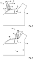
Figures 5 to 7 described hereinafter, theplug connector 3 according to the invention is shown in a side view, wherein thelever arrangement 29 is cut in the region of a sidewall of theconnector housing 11. Theconnector housing 11 is not cut, but thelever 7 and thelever extension 29 are. For a better overview, the axis ofrotation 9 is not shown in all figures. - One can see in
Fig. 5 that thelever extension 29 rests on the guidingmember 49 and prevents a retraction of thelever extension 29 into thelever 7. This movement is blocked by the guidingmember 49, i. e. the slidingsurface 51. Furthermore, one can also see in this representation that in the region of theinterruption 55, the guidingmember 49 ends in thepocket 57. - If the
lever device 13 is moved with theswivel movement 27, thelever extension 29 is no longer in contact with the guidingmember 49 in the region of theinterruption 55, as is shown inFig. 6 . By retracting thelever extension 29 towards the axis ofrotation 9, the retracted state 61 of thelever extension 29 shown inFig. 7 is reached. - This retracted state 61 of the
lever extension 29 is also shown in the perspective representation of theplug connector 3 according to the invention ofFig. 8 . In the latter, thelever 7 is drawn in a semi-transparent manner for illustration purposes. InFigures 7 and 8 , the lever is in its securingposition 25. - By the retracted
lever extension 29, i. e. since thelever extension 29 is in its retracted state 61, aswivel movement 63 of thelever 7 out of the securingposition 25 towards the plug position 23 (cf.Fig. 1 andFig. 9 ) is blocked by apositive engagement 65 between thepocket 57 and thelever extension 29 in the retracted state 61. In the retracted state 61, thelever extension 29 does not project beyond thelever 7 and is completely within itscubature 67. - One can furthermore see that the latching
elements 43 of thearms 31 of thelever extension 29 are received inopenings 45 of the lever 7 (only one of which can be seen inFig. 8 ), which represent theloss prevention device 47. Theconnector housing 11 also includes a restraining or latchingelement 69. The latter blocks thelever 7 at a latchingtongue 71 which is also shown inFig. 3 . Thepositive engagement 65 between the latchingtongue 71 and the restraining or latchingelement 69 prevents theswivel movement 63. - Thus, the
swivel movement 63 of thelever 7 in the securingposition 25 is blocked on the one hand by the restraining or latchingelement 69 and the corresponding latchingtongue 71, and on the other hand by the retractedlever extension 29. - The swivel movement 27 (cf.
Fig. 5 ) of thelever 7 is blocked by theconnector housing 11 or also by thepositive engagement 65 of the retractedlever extension 29 with thepocket 57. - In
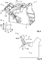
Figures 9 to 13 , another embodiment of theplug connector 3 according to the invention is shown. In this embodiment, the guidingmember 49 comprises alink 73. In this link, a guiding pin 39 (cf.Fig. 4 ) is guided. Preferably, two guidingpins 39 are provided, one on each side of theconnector housing 11. - In
Fig. 9 , thelever extension 29 is received in thelever 7 in its retracted state 61, the lever being in theplug position 23. This provides space advantages which will be described later with respect toFig. 13 . Thelink 73 represents a restraint guiding 75. By this restraint guiding 75, astroke 77 by which thelever extension 29 is extended with respect to thelever 7 depends on anangular position 79 of thelever device 13. - The
angular position 79 of thelever device 13 can vary between the plug position 23 (Fig. 9 ) and the securing position 25 (Figs. 11 and 12 ). A schematic dependence of thestroke 77 on theangular position 79 is shown in a diagram 81 not drawn to scale inFig. 9 . Starting from theplug position 23, thestroke 77 increases to a maximum value (marked by "max") and remains at this maximum value until the securingposition 25 is reached. Since in the securingposition 25, thelever extension 29 can be retracted into thepocket 57, in the securingposition 25, both astroke 77 of 0 (as is shown inFig. 9 ) and amaximum stroke 77 are possible. The latter marks the extended state 59 of thelever extension 29. - Thus, in a
swivel movement 27 of thelever 7 from theplug position 23 to the securingposition 25, thelever extension 29 is extended. - This is already the case in a position between the
plug position 23 and the securingposition 25 as is shown inFig. 10 , wherein thefurther swivel movement 27 is effected with thelever extension 29 in its extended state 59. - Finally, the
lever arrangement 13 or thelever 7, respectively, reaches the securingposition 25, wherein thelever extension 29 is still in its extended state 59. This is shown inFig. 11 . In this position, the guidingpin 39, however, is no longer blocked by thelink 73 since the latter is interrupted at thepocket 57. - As is shown in
Fig. 12 , theinterruption 55, where thepocket 57 is adjacent to thelink 73, permits to transfer thelever extension 29 to the retracted state 61, wherein at least some sections of thelever extension 29 are here received in thepocket 57. In the second embodiment of theplug connector 3 according to the invention, too, thus apositive engagement 65 between thepocket 57 and thelever extension 29 in its retracted state 61 which blocks aswivel movement 63 is created. - It should be pointed out that the embodiment of the
link 73 shown inFigs. 10 to 12 differs from thelink 73 ofFig. 9 . InFig. 10 , thelink 73 ofFig. 9 is schematically shown in a dotted line and designated withreference numeral 73a. - In
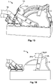
Figs. 13 and 14 , the two exemplary embodiments of theplug connector 3 according to the invention are shown in a corresponding connector set 1 according to the invention. These figures are to illustrate the advantages over the solutions from prior art which are shown inFigs. 1 and 2 . In theplug position 23 of thelever 7 ofFig. 13 , at theend 17 of thelever arrangement 13, the connector set 1 according to the invention does not contact thefeed cables 19 which increases operability. - A further advantage of the connector set 1 according to the invention is shown in
Fig. 14 in which thelever 7 is in its securingposition 25, and the lever extension 29 (concealed by the lever 7) is in its retracted state 61. Aprojection 21b that can be achieved with the solution according to the invention is clearly smaller than theprojection 21 a of the solution from prior art (Fig. 2 ), so that a smaller installation space is required. -
- 1
- connector set
- 3
- plug connector
- 5
- counter connector
- 7
- lever
- 7a
- lever arms
- 9
- axis of rotation
- 11
- connector housing
- 13
- lever device
- 15
- coupling
- 17
- end of the lever
- 19
- feed cables
- 21a
- projection (prior art)
- 21b
- projection (invention)
- 23
- plug position
- 25
- securing position
- 27
- swivel movement
- 29
- lever extension
- 29a
- lever extension of the first embodiment
- 29b
- lever extension of the second embodiment
- 31
- arm
- 33
- basis
- 35
- latching region
- 37
- inner side
- 39
- guiding pin
- 41
- outer side
- 43
- latching elements
- 45
- opening
- 47
- loss prevention device
- 49
- guiding member
- 51
- sliding surface
- 52
- support surface
- 53
- upper region
- 55
- interruption
- 57
- 58
- radial pocket
- 59
- extended state
- 61
- retracted state
- 63
- swivel movement
- 65
- positive engagement
- 67
- cubature
- 69
- restraining or latching element
- 71
- latching tongue
- 73
- link
- 73a
- link
- 75
- restraint guiding
- 77
- stroke
- 79
- angular position
- 81
- diagram
- F
- plug force
- L
- lever length
Claims (15)
- Plug connector (3) for plugging together with a counter connector (5), the plug connector (3) comprising:- a connector housing (11); and- a lever device (13) with a lever (7) that is configured to be transferred from a plug position (23) to a securing position (25), and with a coupling (15) that is movable by the lever (7) and that may be engaged with the counter connector (5),wherein a lever extension (29) is attached to the lever (7), which is extendable and/or retractable with respect to the lever (7), wherein in the securing position (25) of the lever (7), a swivel movement (63) of the lever (7) out of the securing position (25) is blocked by the retracted lever extension (29), and wherein the connector housing (11) comprises a guiding member (49) by which a shifting-in of the lever extension (29) is blocked if the lever (7) is moved out of the plug position (23) and is not in the securing position (25).
- Plug connector (3) according to claim 1, wherein the guiding member (49) is designed as a restraint guiding (75) by which the lever extension (29) is shifted with respect to the lever (7) along a swivel movement (27, 63) of the lever (7).
- Plug connector (3) according to claim 1 or 2, wherein the guiding member (49) comprises at least one link (73) at the connector housing (11) in which the lever extension (29) is guided.
- Plug connector (3) according to one of claims 1 to 3, wherein at the connector housing (11), a pocket (57) is provided in which the lever extension (29) is received in its retracted state (61).
- Plug connector (3) according to claim 4, wherein the guiding member (49) ends in the pocket (57).
- Plug connector (3) according to claim 4 or 5, wherein in the securing position (25), the lever extension (29) being adapted to be inserted into the pocket (57).
- Plug connector (3) according to one of claims 4 to 6, wherein the lever extension (29) includes two legs (30), and the connector housing (11) includes two opposed pockets (57), and wherein the legs (30) of the lever extension (29) is adapted to be inserted into the pockets (57) in the securing position (25).
- Plug connector (3) according to one of claims 1 to 7, wherein the retracted lever extension (29) does not project beyond the lever (7).
- Plug connector (3) according to one of claims 1 to 8, wherein a stroke (77) by which the lever extension (29) is extended with respect to the lever (7) depends on an angular position (79) of the lever device (13).
- Plug connector (3) according to claim 9, wherein the stroke (77) by which the lever extension (29) is extended with respect to the lever (7) increases during the transfer of the lever device (13) from the plug position (23) towards the securing position (25).
- Plug connector (3) according to one of claims 1 to 10, wherein the lever extension (29) is shiftably held at the lever (7) linearly towards an axis of rotation (9) of the lever device (13).
- Plug connector (3) according to one of claims 1 to 11, wherein the lever extension (29) includes a loss prevention device (47) by which the lever extension (29) is held captively at the lever (7).
- Plug connector (3) according to one of claims 1 to 12, wherein the connector housing (11) includes a restraining or latching element (69) by which a swivel movement (63) of the lever (7) in the securing position (25) out of the securing position (25) is restrained or blocked.
- Connector set (1), comprising a plug connector (3) according to one of claims 1 to 13, and a counter connector (5) with coupling elements that are adapted to be engaged with the coupling (15) of the plug connector (1).
- Connector set (1) according to claim 14, wherein the lever extension (29) of the plug connector (1) is a housing retention which is adapted to be only be transferred to the retracted state (61) with a correct plug connection between the plug connector (3) and the counter connector.
Applications Claiming Priority (1)
| Application Number | Priority Date | Filing Date | Title |
|---|---|---|---|
| DE102021112898.6A DE102021112898A1 (en) | 2021-05-18 | 2021-05-18 | Plug and plug set with a lever extension |
Publications (1)
| Publication Number | Publication Date |
|---|---|
| EP4092841A1 true EP4092841A1 (en) | 2022-11-23 |
Family
ID=81748536
Family Applications (1)
| Application Number | Title | Priority Date | Filing Date |
|---|---|---|---|
| EP22173953.5A Pending EP4092841A1 (en) | 2021-05-18 | 2022-05-18 | Plug connector and connector set with a lever extension |
Country Status (6)
| Country | Link |
|---|---|
| US (1) | US12040575B2 (en) |
| EP (1) | EP4092841A1 (en) |
| JP (1) | JP7434411B2 (en) |
| KR (1) | KR102732501B1 (en) |
| CN (1) | CN115377728B (en) |
| DE (1) | DE102021112898A1 (en) |
Families Citing this family (3)
| Publication number | Priority date | Publication date | Assignee | Title |
|---|---|---|---|---|
| DE102022118993A1 (en) * | 2022-07-28 | 2024-02-08 | Te Connectivity Germany Gmbh | Housing arrangement for an electrical plug with a plug-in aid as well as electrical plug and plug arrangement |
| DE102023105353A1 (en) * | 2023-03-03 | 2024-09-05 | Te Connectivity Solutions Gmbh | Plug-in arrangement |
| EP4550587A1 (en) * | 2023-10-31 | 2025-05-07 | Aptiv Technologies AG | Serration feature based clearance compensation mechanism for an electrical connector |
Citations (6)
| Publication number | Priority date | Publication date | Assignee | Title |
|---|---|---|---|---|
| JPH07220805A (en) * | 1994-02-01 | 1995-08-18 | Ryosei Denso Kk | Connector with lever |
| US5829994A (en) * | 1996-01-26 | 1998-11-03 | The Whitaker Corporation | Lever-type connector |
| US20030190836A1 (en) * | 2002-03-04 | 2003-10-09 | Sumitomo Wiring Systems, Ltd. | Connector having an operable member |
| WO2007044393A2 (en) * | 2005-10-06 | 2007-04-19 | Fci Americas Technology, Inc. | Electrical connector |
| JP2010146950A (en) * | 2008-12-22 | 2010-07-01 | Sumitomo Wiring Syst Ltd | Lever-type connector |
| WO2012007343A1 (en) * | 2010-07-16 | 2012-01-19 | Tyco Electronics France Sas | Connection with connection position assurance (cpa) device on locking element |
Family Cites Families (8)
| Publication number | Priority date | Publication date | Assignee | Title |
|---|---|---|---|---|
| US7175451B2 (en) * | 2005-03-15 | 2007-02-13 | Tyco Electronics Corporation | Lever mated connector assembly with a position assurance device |
| CN101427424A (en) * | 2006-02-21 | 2009-05-06 | 泰科电子公司 | Lever mated connector assembly |
| US7563114B2 (en) * | 2006-02-21 | 2009-07-21 | Tyco Electronics Corporation | Lever mated connector assembly with a low profile position assurance member |
| KR101479054B1 (en) * | 2013-10-21 | 2015-01-07 | 주식회사 유라코퍼레이션 | Connector |
| FR3017003B1 (en) | 2014-01-28 | 2017-10-27 | Delphi Int Operations Luxembourg Sarl | CONNECTION LEVER CONNECTION LEVER |
| IT201700057059A1 (en) | 2017-05-25 | 2018-11-25 | Tyco Electronics Amp Italia Srl | ELECTRIC CONNECTOR WITH TELESCOPIC STRUCTURE |
| DE102017223810B3 (en) | 2017-12-27 | 2019-03-28 | Te Connectivity Germany Gmbh | Plug with an extendable lever arrangement |
| FR3084532B1 (en) | 2018-07-27 | 2023-05-12 | Delphi Int Operations Luxembourg Sarl | CONNECTOR WITH CONNECTION ASSISTANCE LEVER AND METHOD FOR PACKAGING SUCH A CONNECTOR |
-
2021
- 2021-05-18 DE DE102021112898.6A patent/DE102021112898A1/en active Pending
-
2022
- 2022-05-13 JP JP2022079194A patent/JP7434411B2/en active Active
- 2022-05-16 KR KR1020220059583A patent/KR102732501B1/en active Active
- 2022-05-16 CN CN202210533691.6A patent/CN115377728B/en active Active
- 2022-05-17 US US17/746,415 patent/US12040575B2/en active Active
- 2022-05-18 EP EP22173953.5A patent/EP4092841A1/en active Pending
Patent Citations (6)
| Publication number | Priority date | Publication date | Assignee | Title |
|---|---|---|---|---|
| JPH07220805A (en) * | 1994-02-01 | 1995-08-18 | Ryosei Denso Kk | Connector with lever |
| US5829994A (en) * | 1996-01-26 | 1998-11-03 | The Whitaker Corporation | Lever-type connector |
| US20030190836A1 (en) * | 2002-03-04 | 2003-10-09 | Sumitomo Wiring Systems, Ltd. | Connector having an operable member |
| WO2007044393A2 (en) * | 2005-10-06 | 2007-04-19 | Fci Americas Technology, Inc. | Electrical connector |
| JP2010146950A (en) * | 2008-12-22 | 2010-07-01 | Sumitomo Wiring Syst Ltd | Lever-type connector |
| WO2012007343A1 (en) * | 2010-07-16 | 2012-01-19 | Tyco Electronics France Sas | Connection with connection position assurance (cpa) device on locking element |
Also Published As
| Publication number | Publication date |
|---|---|
| DE102021112898A1 (en) | 2022-11-24 |
| KR20220156451A (en) | 2022-11-25 |
| JP2022177809A (en) | 2022-12-01 |
| US20220376435A1 (en) | 2022-11-24 |
| KR102732501B1 (en) | 2024-11-19 |
| CN115377728A (en) | 2022-11-22 |
| JP7434411B2 (en) | 2024-02-20 |
| CN115377728B (en) | 2026-01-13 |
| US12040575B2 (en) | 2024-07-16 |
Similar Documents
| Publication | Publication Date | Title |
|---|---|---|
| US12040575B2 (en) | Plug connector and connector set with a lever extension | |
| EP2235799B1 (en) | Electrical connector | |
| US7563114B2 (en) | Lever mated connector assembly with a low profile position assurance member | |
| EP2947722A1 (en) | Connector assembly with male terminal protector | |
| US9979131B2 (en) | Electrical connector assembly with improved locking device | |
| CN102891385B (en) | Electrical connector | |
| EP3016213A1 (en) | CPA device for direct mating and unmating | |
| KR20120110029A (en) | Connector terminal position assurance device | |
| CN101427424A (en) | Lever mated connector assembly | |
| EP2871722A2 (en) | Terminal position assurance with dual primary lock reinforcement and independent secondary lock | |
| CN110571567B (en) | Staged release electrical connector assembly | |
| US20020039863A1 (en) | Electrical connector assembly with secondary terminal lock | |
| CN114122838A (en) | Connecting device with plug connector and mating plug connector | |
| EP2840665B1 (en) | Arrangement for facilitated connection or separation of a connector and a mating connector | |
| EP3136517B1 (en) | Connector for motor vehicles and method for mounting such a connector | |
| CN112510436A (en) | Electric connector with connector position assurance device | |
| EP2685570B1 (en) | Electrical plug-in connector assembly with locking member | |
| EP3171462A1 (en) | Electric connector with secondary locking member and electric connector assembly | |
| US12126108B2 (en) | Connector having first housing and second housing connectable to each other | |
| EP2380243B1 (en) | Electrical connector assembly | |
| US20260058406A1 (en) | Telescopic lever with connector position assurance (cpa) function | |
| US20250219330A1 (en) | High voltage shielded electrical connector | |
| JP2931273B2 (en) | Electrical connector | |
| JP2002305055A (en) | Connector | |
| EP3487010B1 (en) | Electrical connector |
Legal Events
| Date | Code | Title | Description |
|---|---|---|---|
| PUAI | Public reference made under article 153(3) epc to a published international application that has entered the european phase |
Free format text: ORIGINAL CODE: 0009012 |
|
| STAA | Information on the status of an ep patent application or granted ep patent |
Free format text: STATUS: THE APPLICATION HAS BEEN PUBLISHED |
|
| AK | Designated contracting states |
Kind code of ref document: A1 Designated state(s): AL AT BE BG CH CY CZ DE DK EE ES FI FR GB GR HR HU IE IS IT LI LT LU LV MC MK MT NL NO PL PT RO RS SE SI SK SM TR |
|
| STAA | Information on the status of an ep patent application or granted ep patent |
Free format text: STATUS: REQUEST FOR EXAMINATION WAS MADE |
|
| 17P | Request for examination filed |
Effective date: 20230331 |
|
| RBV | Designated contracting states (corrected) |
Designated state(s): AL AT BE BG CH CY CZ DE DK EE ES FI FR GB GR HR HU IE IS IT LI LT LU LV MC MK MT NL NO PL PT RO RS SE SI SK SM TR |
|
| STAA | Information on the status of an ep patent application or granted ep patent |
Free format text: STATUS: EXAMINATION IS IN PROGRESS |
|
| 17Q | First examination report despatched |
Effective date: 20241121 |