EP4092615A1 - Image processing method and apparatus and storage medium - Google Patents
Image processing method and apparatus and storage medium Download PDFInfo
- Publication number
- EP4092615A1 EP4092615A1 EP21218062.4A EP21218062A EP4092615A1 EP 4092615 A1 EP4092615 A1 EP 4092615A1 EP 21218062 A EP21218062 A EP 21218062A EP 4092615 A1 EP4092615 A1 EP 4092615A1
- Authority
- EP
- European Patent Office
- Prior art keywords
- image
- channel
- color
- denoised
- images
- Prior art date
- Legal status (The legal status is an assumption and is not a legal conclusion. Google has not performed a legal analysis and makes no representation as to the accuracy of the status listed.)
- Granted
Links
Images


Classifications
-
- G—PHYSICS
- G06—COMPUTING OR CALCULATING; COUNTING
- G06T—IMAGE DATA PROCESSING OR GENERATION, IN GENERAL
- G06T5/00—Image enhancement or restoration
- G06T5/70—Denoising; Smoothing
-
- G—PHYSICS
- G06—COMPUTING OR CALCULATING; COUNTING
- G06T—IMAGE DATA PROCESSING OR GENERATION, IN GENERAL
- G06T5/00—Image enhancement or restoration
- G06T5/10—Image enhancement or restoration using non-spatial domain filtering
-
- G—PHYSICS
- G06—COMPUTING OR CALCULATING; COUNTING
- G06T—IMAGE DATA PROCESSING OR GENERATION, IN GENERAL
- G06T5/00—Image enhancement or restoration
- G06T5/20—Image enhancement or restoration using local operators
-
- G—PHYSICS
- G06—COMPUTING OR CALCULATING; COUNTING
- G06T—IMAGE DATA PROCESSING OR GENERATION, IN GENERAL
- G06T5/00—Image enhancement or restoration
- G06T5/50—Image enhancement or restoration using two or more images, e.g. averaging or subtraction
-
- G—PHYSICS
- G06—COMPUTING OR CALCULATING; COUNTING
- G06T—IMAGE DATA PROCESSING OR GENERATION, IN GENERAL
- G06T7/00—Image analysis
- G06T7/90—Determination of colour characteristics
-
- H—ELECTRICITY
- H04—ELECTRIC COMMUNICATION TECHNIQUE
- H04N—PICTORIAL COMMUNICATION, e.g. TELEVISION
- H04N9/00—Details of colour television systems
- H04N9/64—Circuits for processing colour signals
- H04N9/67—Circuits for processing colour signals for matrixing
-
- G—PHYSICS
- G06—COMPUTING OR CALCULATING; COUNTING
- G06T—IMAGE DATA PROCESSING OR GENERATION, IN GENERAL
- G06T2207/00—Indexing scheme for image analysis or image enhancement
- G06T2207/10—Image acquisition modality
- G06T2207/10024—Color image
-
- G—PHYSICS
- G06—COMPUTING OR CALCULATING; COUNTING
- G06T—IMAGE DATA PROCESSING OR GENERATION, IN GENERAL
- G06T2207/00—Indexing scheme for image analysis or image enhancement
- G06T2207/20—Special algorithmic details
- G06T2207/20048—Transform domain processing
- G06T2207/20052—Discrete cosine transform [DCT]
-
- G—PHYSICS
- G06—COMPUTING OR CALCULATING; COUNTING
- G06T—IMAGE DATA PROCESSING OR GENERATION, IN GENERAL
- G06T2207/00—Indexing scheme for image analysis or image enhancement
- G06T2207/20—Special algorithmic details
- G06T2207/20212—Image combination
- G06T2207/20221—Image fusion; Image merging
Definitions
- the present application relates to the technical field of images, in particular to an image processing method and apparatus and a storage medium.
- the present application provides an image processing method and apparatus and a storage medium.
- an image processing method including:
- obtaining the target image based on the denoised images includes:
- fusing the first channel image in all the channel images and the first denoised image corresponding to the first channel image to obtain the composite image includes:
- weighting the color components corresponding to the first channel image and the color components corresponding to the first denoised image based on the composition weights to obtain the weighted color component includes:
- denoising the channel images formed by the color components of the respective channels in the second color space respectively to obtain the denoised images corresponding to the respective channel images includes:
- converting the channel images from the spatial domain to the spectral domain respectively includes: carrying out discrete cosine transform on the channel images respectively to convert the respective channel images from the spatial domain to the spectral domain.
- the color components corresponding to the first channel image are used to represent luminance of the original image; and the color components corresponding to the second channel image are used to represent color of the original image.
- an image processing apparatus including:
- the processor is configured to implement the steps in any image processing method in the above first aspect during execution.
- a non-transitory computer-readable storage medium When instructions in the storage medium are executed by a processor of an image processing apparatus, the apparatus is capable of executing any image processing method in the above first aspect.
- a computer program product including a computer program executable by a programmable device, in which the computer program has code portions implementing any image processing method in the above first aspect when executed by the programmable device.
- the original image may be converted from the first color space to the second color space. Since the correlation between the color components of the respective channels in the second color space of the original image is smaller than the correlation between the color components of the respective channels in the first color space, by utilizing the conversion between the color spaces, the correlation between the color components of the respective channels corresponding to the original image can be weakened, so that the channel images formed by the color components of the respective channels can be denoised respectively, thereby realizing denoising of the color components of different channels at the same time. The operation is convenient, and denoising effect can be improved, thereby ensuring the quality of the finally obtained target image.
- channels of a collected image have a large correlation in an original color space and most of current denoising methods are limited to a fixed color space, so that a color component corresponding to one channel can be subjected to denoising at a time.
- a color component corresponding to one channel can be subjected to denoising at a time.
- one of a luminance component or a color component can be denoised, so that the obtained image has poor quality.
- FIG. 1 is a flow chart of an image processing method shown according to an example. As shown in FIG. 1 , the method includes the following steps:
- step 101 converting an original image represented by a first color space into the original image represented by a second color space, where a correlation between color components of respective channels in the second color space of the original image is smaller than a correlation between color components of respective channels in the first color space.
- step 102 denoising channel images formed by the color components of the respective channels in the second color space respectively to obtain denoised images corresponding to the respective channel images; and in step 103, obtaining a target image based on the denoised images.
- the image processing method involved in the example of the present application may be applied to an electronic device.
- the electronic device includes a mobile terminal and a fixed terminal.
- the mobile terminal includes: a mobile phone, a tablet computer, a notebook computer, etc.
- the fixed terminal includes: a personal computer.
- the image processing method may also run on a network-side device.
- the network-side device includes a server, a processing center, etc.
- the electronic device may also be a camera that can be used alone, or a camera that can be embedded in a terminal device.
- the original image may be an image collected by an image collection module of the electronic device, or an image pre-stored on the electronic device, or an image acquired by the electronic device from other devices, which is not specifically limited here.
- the original image may be an image with noise represented by the first color space.
- the original image represented by the first color space may be converted into the original image represented by the second color space.
- the first color space may include: an RGB color space.
- R represents a red channel
- G represents a green channel
- B represents a blue channel.
- the second color space may include: an L ⁇ color space, L represents a luminance component, ⁇ and ⁇ represent two chroma components, ⁇ represents a yellow-blue opponent channel, and ⁇ represents a red-green opponent channel.
- the first color space may further include: an LMS color space, L represents a first main component, M represents a second main component, and S represents a third main component.
- the first color space may include: an HSV color space, H represents hue, S represents saturation, and V represents value.
- the channel images formed by the color components of the respective channels in the second color space can be denoised respectively to obtain the denoised images corresponding to the respective channel images.
- the second color space has a first channel, a second channel and a third channel.
- color components in the first channel, the second channel and the third channel can be denoised respectively, so that three denoised images can be obtained.
- the original image can be converted from the RGB color space to the LMS color space, and then converted from the LMS color space to the L ⁇ color space.
- L, M and S represent values of the LMS color space
- R, G and B represent values of the RGB color space.
- L, M and S represent values of the LMS color space; and L, ⁇ and ⁇ represent values of the L ⁇ color space.
- the logarithm of the color components of the channels in the LMS color space is found respectively in order to converge data and make color distribution more in line with the perception of human eyes.
- the three channels of the color image (original image) can be separated, and the color image can be converted to the LMS color space, and then converted to the L ⁇ color space by orthogonalization and decorrelation. Then, the L, ⁇ and ⁇ channels are subjected to denoising respectively after domain conversion, and the target image in the L ⁇ color space is converted into a required color space format, so that the denoised color image can be obtained.
- the denoising after domain conversion mainly as follows: the original image is converted from a spatial domain to a spectral domain by discrete cosine transform, adaptive Gaussian smoothing is carried out on the image converted to the spectral domain, and then inverse discrete cosine transform is carried out on the image subjected to Gaussian smoothing to obtain the denoised image.
- noise can be separated more effectively by using the adaptive Gaussian smoothing operation.
- the original image may be converted from the first color space to the second color space. Since the correlation between the color components of the respective channels in the second color space of the original image is smaller than the correlation between the color components of the respective channels in the first color space, by utilizing the conversion between the color spaces, the correlation between the color components of the respective channels corresponding to the original image can be weakened, so that the channel images formed by the color components of the respective channels can be denoised respectively, and the denoising of the color components of different channels at the same time can be realized.
- the operation is convenient, and denoising effect can be improved, such that the quality of the finally obtained target image can be ensured.
- the target image represented by the second color space can be converted into the target image represented by a target color space.
- the target image can be converted from the L ⁇ color space to the LMS color space, and then converted from the LMS color space to the RGB color space.
- L M S 1 1 1 1 1 1 ⁇ 1 1 ⁇ 2 0 1 3 0 0 0 1 6 0 0 0 1 2 L ⁇ ⁇ in formula (3), L, M and S represent values of the LMS color space; and L, ⁇ and ⁇ represent values of the L ⁇ color space.
- the target color space may include: the LMS color space, the HSV color space and the like, which is not specifically limited here.
- denoising the channel images formed by the color components of the respective channels in the second color space respectively to obtain the denoised images corresponding to the respective channel images includes:
- converting the channel images from the spatial domain to the spectral domain respectively includes: carrying out discrete cosine transform on the channel images respectively to convert the respective channel images from the spatial domain to the spectral domain.
- discrete cosine transform can be carried out on the color components of the respective channels in the second color space so that the channel images formed by the color components of the respective channels can be converted from the spatial domain to the spectral domain, and Gaussian smoothing can be carried out on the channel images in the spectral domain respectively.
- Gaussian smoothing inverse discrete cosine transform is carried out on the channel images subjected to Gaussian smoothing to obtain the denoised images corresponding to the respective channel images.
- a low-frequency part, an intermediate-frequency part and a high-frequency part in the respective channel images are distributed in a set order from an upper left corner to a lower right corner of the respective channel images.
- adaptive Gaussian smoothing can be carried out on the respective channel images in the spectral domain, which is equivalent to carrying out different threshold limited filtrations on different spatial frequencies, for example, an adaptive threshold can be set for the high-frequency part.
- inverse discrete cosine transform is carried out on the channel images subjected to Gaussian smoothing to obtain the denoised images corresponding to the respective channel images.
- T ( ⁇ , ⁇ ) represents distribution of the spectral domain of the single-channel image subjected to adaptive Gaussian smoothing
- ⁇ and ⁇ represent base coordinates in the spectral domain
- O ( r, ⁇ ) represents the single-channel image
- r and ⁇ represent base coordinates in the spatial domain
- D [ ] represents a discrete cosine transform function
- Gauss ( r - r 0 , ⁇ ) represents a function whose value varies with radius by taking the upper left corner of the single-channel image as the center of a circle
- r 0 represents a distance of variation of the center of the circle, that is, a distance from
- the single-channel image may be any channel image in the second color space. Taking the second color space being the L ⁇ color space as an example, the single-channel image may be any of an L channel image, a ⁇ channel image and a ⁇ channel image.
- O' ( r, ⁇ ) represents the denoised single-channel image
- T ( ⁇ , ⁇ ) represents distribution of the spectral domain of the single-channel image subjected to adaptive Gaussian smoothing
- D -1 [ ] represents an inverse discrete cosine transform function
- the channel images converted to the spectral domain are denoised respectively.
- the discrete cosine transform and the Gaussian smoothing of the spectral domain are used to denoise the channel images respectively, so that a good denoising effect can be realized.
- obtaining the target image based on the denoised images includes:
- the first channel image and the first denoised image corresponding to the first channel image can be fused to obtain the composite image.
- the first channel image may be the L channel image; and the second channel image may include the ⁇ channel image and the ⁇ channel image. That is, in an implementation process, the original L channel image and the denoised image of the L channel image can be fused to obtain the composite image.
- the fusing process may be as follows: color components for forming the composite image is obtained by means of summing and averaging the respective color components in the first channel image and the respective color components in the first denoised image, so that the composite image is obtained.
- the first channel image and the first denoised image may also be fused based on other manners, which are not specifically limited here.
- the target image may be obtained based on the composite image and the second denoised image corresponding to the second channel image other than the first channel image.
- the color components of the composite image and the color components of the second denoised image may be used as the color components of the respective channels of the target image respectively.
- the color components of the composite image may be determined as the color components of the L channel
- the color components of the first denoised image may be determined as the color components of the ⁇ channel
- the color components of the second denoised image may be determined as the color components of the ⁇ channel.
- the target image is obtained based on the composite image and the second denoised image corresponding to the second channel image other than the first channel image, so that the obtained target image is more natural and more in line with the perception of human eyes.
- a number of the first channel images may be at least one, a number of the second channel images may also be at least one, and here, the number of the first channel images and the number of the second channel images may be the same or different.
- the number of the first channel images may be one, and the number of the second channel images may be two.
- the number of the first channel images may be two, and the number of the second channel images may be one.
- the number of the first channel images and the number of the second channel images are both one, which will not be illustrated one by one here.
- image quality parameters of the composite image may be determined, and whether the image quality parameters are greater than preset standard quality parameters may be determined.
- the target image is obtained based on the composite image and the second denoised image corresponding to the second channel image other than the first channel image.
- the image quality parameters may include: image luminance, image saturation, image color, or other parameters, which are not specifically limited here.
- the standard quality parameters may be set according to needs, for example, may be set according to empirical values, or may also be set according to historical image parameters, or furthermore, may further be set according to user needs, which are not specifically limited here.
- fusing the first channel image in all the channel images and the first denoised image corresponding to the first channel image to obtain the composite image includes:
- the first channel image and the first denoised image may be weighted based on the composition weights to obtain the weighted color component, and the composite image is formed based on the weighted color component.
- the original image of the first channel (first channel image) and the denoised image (first denoised image) may be composited first to obtain the composite image, and the proportions of the first channel image and the first denoised image in the composite image may be controlled by setting the composition weights, so that image details can be reserved on the basis of denoising of the composite image, such that the high-quality composite image is obtained.
- weighting the color components corresponding to the first channel image and the color components corresponding to the first denoised image based on the composition weights to obtain the weighted color component includes:
- the first composition weight and the second composition weight may be preset, or may also be determined according to current image parameters of the first channel image and the second denoised image.
- the current image parameters of the first channel image and the second denoised image may be acquired, and then input into a pre-trained parameter determination model to obtain corresponding first composition weight and second composition weight.
- the parameter determination model may be obtained by training based on a neural network model.
- the first composition weight and the second composition weight may be customized, or the first composition weight and the second composition weight may also be determined according to historical empirical values.
- manners for determining the first composition weight and the second composition weight will not be enumerated one by one.
- the original image of the first channel (first channel image) and the denoised image (first denoised image) may be composited first to obtain the composite image, and the proportions of the first channel image and the first denoised image may be controlled by setting coefficients (the first composition weight and the second composition weight), so that image details can be reserved on the basis of denoising of the composite image, such that the high-quality composite image is obtained.
- the type of the first channel image may be different from the type of the second channel image.
- the color components corresponding to the first channel image are used to represent the luminance of the original image
- the color components corresponding to the second channel image are used to represent the color of the original image.
- the color components corresponding to the first channel image are used to represent the color of the original image
- the color components corresponding to the second channel image are used to represent the luminance of the original image.
- the type of the first channel image may be the same as the type of the second channel image.
- the color components corresponding to the first channel image and the second channel image are both used to represent the luminance of the original image; or, the color components corresponding to the first channel image and the second channel image are both used to represent the color of the original image.
- the color components corresponding to the first channel image are used to represent the luminance of the original image.
- the color components corresponding to the second channel image are used to represent the color of the original image.
- the image processing method adds a manner for reducing color noise, and the denoising effect is optimized and regulated by using Gaussian smoothing filtration.
- FIG. 2 is a flow chart of another image processing method shown according to an example. As shown in FIG. 2 , the method includes the following steps:
- step 201 an original image represented by a first color space is input.
- step 202 the original image is converted from the first color space to a third color space.
- step 203 the original image is converted from the third color space to a second color space.
- the original image can be converted from the RGB color space to the LMS color space, and then converted from the LMS color space to the L ⁇ color space.
- step 204 discrete cosine transform is carried out on a first channel image.
- the first channel image may be the L channel image.
- step 205 Gaussian smoothing is carried out on a discrete cosine transform result corresponding to the first channel image.
- step 206 inverse discrete cosine transform is carried out on a Gaussian smoothing result corresponding to the first channel image to obtain a first denoised image.
- step 207 the first channel image and the first denoised image are fused to obtain a composite image.
- step 208 discrete cosine transform is carried out on a second channel image other than the first channel image.
- the first channel image may include: the L channel image
- the second channel image may include: the ⁇ channel image and the ⁇ channel image.
- the first channel image may include: the ⁇ channel image; and the second channel image may include: the L channel image and the ⁇ channel image.
- the first channel image may include: the ⁇ channel image and the ⁇ channel image, and the second channel image may include: the L channel image.
- the types of the first channel image and the second channel image may be set according to needs and will not be illustrated one by one here.
- step 209 Gaussian smoothing is carried out on a discrete cosine transform result corresponding to the second channel image.
- step 210 inverse discrete cosine transform is carried out on a Gaussian smoothing result corresponding to the second channel image to obtain a second denoised image.
- step 211 a target image represented by the second color space is obtained based on the composite image and the second denoised image.
- step 212 the target image represented by the second color space is converted into the target image represented by a target color space.
- step 213 the target image represented by the target color space is output.
- the respective channels are subjected to decorrelation by utilizing the orthogonality of the color spaces, so that the correlation between the respective channels of the image is greatly reduced, which is beneficial to the denoising effect.
- the original image is converted from the spatial domain to the spectral domain by discrete cosine transform, adaptive Gaussian smoothing is carried out on the image converted to the spectral domain, and then inverse discrete cosine transform is carried out on the image subjected to Gaussian smoothing to obtain the denoised image, so that a good denoising effect can be realized.
- the image processing method adds a manner for reducing color noise, and the denoising effect can be optimized by using Gaussian smoothing filtration.
- FIG. 3 is a block diagram of an image processing apparatus shown according to an example. As shown in FIG. 3 , the apparatus 300 mainly includes:
- a conversion module 301 configured to convert an original image represented by a first color space into the original image represented by a second color space, where a correlation between color components of respective channels in the second color space of the original image is smaller than a correlation between color components of respective channels in the first color space;
- a denoising module 302 configured to denoise channel images formed by the color components of the respective channels in the second color space respectively to obtain denoised images corresponding to the respective channel images
- an acquisition module 303 configured to obtain a target image based on the denoised images.
- the acquisition module 303 is configured to:
- the acquisition module 303 is configured to:
- the acquisition module 303 is configured to:
- the denoising module 302 is configured to:
- the denoising module is configured to:
- the color components corresponding to the first channel image are used to represent the luminance of the original image.
- the color components corresponding to the second channel image are used to represent the color of the original image.
- FIG. 4 is a block diagram of an apparatus 1200 for image processing shown according to an example.
- the apparatus 1200 may be a mobile phone, a computer, a digital broadcasting terminal, a message transceiving device, a game console, a tablet device, a medical device, a fitness device, a personal digital assistant or the like.
- the apparatus 1200 may include one or more of the following components: a processing component 1202, a memory 1204, an electrical component 1206, a multimedia component 1208, an audio component 1210, an input/output (I/O) interface 1212, a sensor component 1214 and a communication component 1216.
- a processing component 1202 a memory 1204, an electrical component 1206, a multimedia component 1208, an audio component 1210, an input/output (I/O) interface 1212, a sensor component 1214 and a communication component 1216.
- the processing component 1202 generally controls overall operations of the apparatus 1200, such as operations associated with display, telephone calls, data communication, camera operations and recording operations.
- the processing component 1202 may include one or more processors 1220 to execute instructions to complete all or part of the steps of the above method.
- the processing component 1202 may include one or more modules to facilitate the interaction between the processing component 1202 and other components.
- the processing component 1202 may include a multimedia module to facilitate the interaction between the multimedia component 1208 and the processing component 1202.
- the memory 1204 is configured to store various types of data to support operations in the apparatus 1200. Examples of these data include instructions for any application or method operating on the apparatus 1200, contact data, phone book data, messages, pictures, videos and the like.
- the memory 1204 may be implemented by any type of volatile or non-volatile storage device or a combination of them, such as a static random access memory (SRAM), an electrically erasable programmable read-only memory (EEPROM), an erasable programmable read-only memory (EPROM), a programmable read-only memory (PROM), a read-only memory (ROM), a magnetic memory, a flash memory, a magnetic disk or an optical disk.
- SRAM static random access memory
- EEPROM electrically erasable programmable read-only memory
- EPROM erasable programmable read-only memory
- PROM programmable read-only memory
- ROM read-only memory
- magnetic memory a magnetic memory
- flash memory a flash memory
- the electrical component 1206 provides electric power to various components of the apparatus 1200.
- the electrical component 1206 may include a power supply management system, one or more power supplies, and other components associated with generation, management and distribution of power for the apparatus 1200.
- the multimedia component 1208 includes a screen that provides an output interface between the apparatus 1200 and the user.
- the screen may include a liquid crystal display (LCD) and a touch panel (TP). If the screen includes the touch panel, the screen may be implemented as a touch screen to receive input signals from the user.
- the touch panel includes one or more touch sensors to sense touch, slide and gestures on the touch panel. The touch sensor may sense the boundary of a touch or slide operation, and also detect the duration and pressure related to the touch or slide operation.
- the multimedia component 1208 includes a front camera and/or a rear camera. When the apparatus 1200 is in an operation mode, such as a shooting mode or a video mode, the front camera and/or the rear camera can receive external multimedia data.
- Each of the front camera and the rear camera may be a fixed optical lens system or have focal length and optical zoom capabilities.
- the audio component 1210 is configured to output and/or input audio signals.
- the audio component 1210 includes a microphone (MIC).
- the microphone is configured to receive an external audio signal.
- the received audio signal may be further stored in the memory 1204 or transmitted via the communication component 1216.
- the audio component 1210 further includes a speaker for outputting audio signals.
- the I/O interface 1212 provides an interface between the processing component 1202 and a peripheral interface module.
- the above peripheral interface module may be a keyboard, a click wheel, buttons and the like. These buttons may include, but are not limited to: a home button, a volume button, a start button and a lock button.
- the sensor component 1214 includes one or more sensors for providing various aspects of state evaluation to the apparatus 1200.
- the sensor component 1214 may detect an on/off state of the apparatus 1200 and the relative positioning of the components.
- the components are a display and a keypad of the apparatus 1200.
- the sensor component 1214 may also detect the position change of the apparatus 1200 or a component of the apparatus 1200, the presence or absence of contact between a user and the apparatus 1200, the orientation or acceleration/deceleration of the apparatus 1200, and the temperature change of the apparatus 1200.
- the sensor component 1214 may include a proximity sensor configured to detect the presence of nearby objects when there is no physical contact.
- the sensor component 1214 may further include a light sensor, such as a CMOS or CCD image sensor, for use in imaging application.
- the sensor component 1214 may further include an acceleration sensor, a gyroscope sensor, a magnetic sensor, a pressure sensor or a temperature sensor.
- the communication component 1216 is configured to facilitate wired or wireless communication between the apparatus 1200 and other devices.
- the apparatus 1200 may access a wireless network based on a communication standard, such as WiFi, 4G or 5G, or a combination of them.
- the communication component 1216 receives a broadcast signal from an external broadcast management system or broadcasts related information via a broadcast channel.
- the communication component 1216 further includes a near field communication (NFC) module to facilitate short-range communication.
- the NFC module can be implemented based on radio frequency identification (RFID) technology, infrared data association (IrDA) technology, ultra-wideband (UWB) technology, Bluetooth (BT) technology and other technologies.
- RFID radio frequency identification
- IrDA infrared data association
- UWB ultra-wideband
- Bluetooth Bluetooth
- the apparatus 1200 may be implemented by one or more application specific integrated circuits (ASICs), digital signal processors (DSPs), digital signal processing devices (DSPDs), programmable logic devices (PLDs), field programmable gate arrays (FPGAs), controllers, microcontrollers, microprocessors or other electronic elements, and is used to execute the above method.
- ASICs application specific integrated circuits
- DSPs digital signal processors
- DSPDs digital signal processing devices
- PLDs programmable logic devices
- FPGAs field programmable gate arrays
- controllers microcontrollers, microprocessors or other electronic elements, and is used to execute the above method.
- a non-transitory computer-readable storage medium including instructions is further provided, for example, a memory 1204 including instructions.
- the above instructions may be executed by the processor 1220 of the apparatus 1200 to complete the above method.
- the non-transitory computer-readable storage medium may be an ROM, a random access memory (RAM), a CD-ROM, a magnetic tape, a floppy disk, an optical data storage device or the like.
- a non-transitory computer-readable storage medium When instructions in the storage medium are executed by a processor of an image processing apparatus, the image processing apparatus is capable of executing an image processing method.
- the method includes:
- denoising channel images formed by the color components of the respective channels in the second color space respectively to obtain denoised images corresponding to the respective channel images; and obtaining a target image based on the denoised images.
- FIG. 5 is a block diagram of another apparatus 1300 for image processing shown according to an example.
- the apparatus 1300 may be provided as a server.
- the apparatus 1300 includes a processing component 1322 which further includes one or more processors, and a memory resource represented by a memory 1332, for storing instructions executable by the processing component 1322, such as applications.
- Applications stored in the memory 1332 may include one or more modules each corresponding to a set of instructions.
- the processing component 1322 is configured to execute instructions to execute the above image processing method. The method includes:
- denoising channel images formed by the color components of the respective channels in the second color space respectively to obtain denoised images corresponding to the respective channel images; and obtaining a target image based on the denoised images.
- the apparatus 1300 may further include a power supply component 1326 configured to execute power supply management of the apparatus 1300, a wired or wireless network interface 1350 configured to connect the apparatus 1300 to the network, and an input/output (I/O) interface 1358.
- the apparatus 1300 can operate based on an operating system stored in the memory 1332, for example, Windows Server TM , Mac OS X TM , Unix TM , Linux TM , FreeBSD TM or the like.
Landscapes
- Engineering & Computer Science (AREA)
- Physics & Mathematics (AREA)
- General Physics & Mathematics (AREA)
- Theoretical Computer Science (AREA)
- Multimedia (AREA)
- Signal Processing (AREA)
- Computer Vision & Pattern Recognition (AREA)
- Image Processing (AREA)
Abstract
Description
- The present application relates to the technical field of images, in particular to an image processing method and apparatus and a storage medium.
- In related art, in order to improve the quality of a collected image, after the image is collected, it is necessary to carry out denoising on the collected image. As the image processing techniques play an increasingly important role in the fields of artificial intelligence (AI) recognition, fingerprint detection, automatic driving, etc., the influence of a denoising algorithm is increasing day by day.
- The present application provides an image processing method and apparatus and a storage medium.
- According to a first aspect of examples of the present application, provided is an image processing method, including:
- converting an original image represented by a first color space into the original image represented by a second color space, where a correlation between color components of channels in the second color space of the original image is smaller than a correlation between color components of channels in the first color space; and
- denoising channel images formed by the color components of the respective channels in the second color space respectively to obtain denoised images corresponding to the respective channel images; and
- obtaining a target image based on the denoised images.
- Optionally, obtaining the target image based on the denoised images includes:
- fusing a first channel image in all the channel images and a first denoised image corresponding to the first channel image to obtain a composite image; and
- obtaining the target image based on the composite image and a second denoised image corresponding to a second channel image other than the first channel image.
- Optionally, fusing the first channel image in all the channel images and the first denoised image corresponding to the first channel image to obtain the composite image includes:
- weighting color components corresponding to the first channel image and color components corresponding to the first denoised image based on composition weights to obtain a weighted color component; and
- fusing based on the weighted color component to form the composite image.
- Optionally, weighting the color components corresponding to the first channel image and the color components corresponding to the first denoised image based on the composition weights to obtain the weighted color component includes:
- weighting the color components of the respective channels of the first channel image based on a first composition weight to obtain a first weighted component;
- weighting the color components of the respective channels corresponding to the first denoised image based on a second composition weight to obtain a second weighted component; and
- determining a sum of the first weighted component and the second weighted component as the weighted color component.
- Optionally, denoising the channel images formed by the color components of the respective channels in the second color space respectively to obtain the denoised images corresponding to the respective channel images includes:
- converting the channel images from a spatial domain to a spectral domain respectively; and
- denoising the channel images converted to the spectral domain respectively to obtain the denoised images corresponding to the respective channel images.
- Optionally, converting the channel images from the spatial domain to the spectral domain respectively includes:
carrying out discrete cosine transform on the channel images respectively to convert the respective channel images from the spatial domain to the spectral domain. - Optionally, the color components corresponding to the first channel image are used to represent luminance of the original image; and
the color components corresponding to the second channel image are used to represent color of the original image. - According to a second aspect of examples of the present application, provided is an image processing apparatus, including:
- a processor; and
- a memory storing executable instructions of the processor.
- The processor is configured to implement the steps in any image processing method in the above first aspect during execution.
- According to a third aspect of examples of the present application, provided is a non-transitory computer-readable storage medium. When instructions in the storage medium are executed by a processor of an image processing apparatus, the apparatus is capable of executing any image processing method in the above first aspect.
- According to a fourth aspect of examples of the present application, provided is a computer program product, including a computer program executable by a programmable device, in which the computer program has code portions implementing any image processing method in the above first aspect when executed by the programmable device.
- Technical solutions provided by the examples of the present application may include the following beneficial effects:
- In the examples of the present application, the original image may be converted from the first color space to the second color space. Since the correlation between the color components of the respective channels in the second color space of the original image is smaller than the correlation between the color components of the respective channels in the first color space, by utilizing the conversion between the color spaces, the correlation between the color components of the respective channels corresponding to the original image can be weakened, so that the channel images formed by the color components of the respective channels can be denoised respectively, thereby realizing denoising of the color components of different channels at the same time. The operation is convenient, and denoising effect can be improved, thereby ensuring the quality of the finally obtained target image.
- Understandably, the above general description and the following detailed description are exemplary and explanatory and cannot limit the present application.
- The accompanying drawings here are incorporated into the specification and constitute a part of the specification, show the examples that comply with the present application, and are used to explain the principle of the present application together with the specification.
-
FIG. 1 is a flow chart of an image processing method shown according to an example. -
FIG. 2 is a flow chart of another image processing method shown according to an example. -
FIG. 3 is a block diagram of an image processing apparatus shown according to an example. -
FIG. 4 is a block diagram of an apparatus for image processing shown according to an example. -
FIG. 5 is a block diagram of another apparatus for image processing shown according to an example. - Some examples will be illustrated in detail here, and examples of the application are shown in the drawings. When the following description involves the drawings, unless otherwise indicated, the same numeral in different drawings indicates the same or similar elements. The implementation modes described in the following examples do not represent all implementation modes consistent with the present application. On the contrary, they are merely examples of apparatuses and methods consistent with some aspects of the present application as described in detail in the appended claims.
- In related art, channels of a collected image have a large correlation in an original color space and most of current denoising methods are limited to a fixed color space, so that a color component corresponding to one channel can be subjected to denoising at a time. For example, one of a luminance component or a color component can be denoised, so that the obtained image has poor quality.
- An example of the present application provides an image processing method.
FIG. 1 is a flow chart of an image processing method shown according to an example. As shown inFIG. 1 , the method includes the following steps: - In
step 101, converting an original image represented by a first color space into the original image represented by a second color space, where a correlation between color components of respective channels in the second color space of the original image is smaller than a correlation between color components of respective channels in the first color space. - In
step 102, denoising channel images formed by the color components of the respective channels in the second color space respectively to obtain denoised images corresponding to the respective channel images; and instep 103, obtaining a target image based on the denoised images. - The image processing method involved in the example of the present application may be applied to an electronic device. Here, the electronic device includes a mobile terminal and a fixed terminal. The mobile terminal includes: a mobile phone, a tablet computer, a notebook computer, etc. The fixed terminal includes: a personal computer. In other optional examples, the image processing method may also run on a network-side device. The network-side device includes a server, a processing center, etc. Certainly, the electronic device may also be a camera that can be used alone, or a camera that can be embedded in a terminal device.
- In the example of the present application, the original image may be an image collected by an image collection module of the electronic device, or an image pre-stored on the electronic device, or an image acquired by the electronic device from other devices, which is not specifically limited here. In some examples, the original image may be an image with noise represented by the first color space.
- In the example of the present application, after the original image with noise is acquired, the original image represented by the first color space may be converted into the original image represented by the second color space.
- Here, the first color space may include: an RGB color space. R represents a red channel, G represents a green channel, and B represents a blue channel. The second color space may include: an Lαβ color space, L represents a luminance component, α and β represent two chroma components, α represents a yellow-blue opponent channel, and β represents a red-green opponent channel. Certainly, in other examples, the first color space may further include: an LMS color space, L represents a first main component, M represents a second main component, and S represents a third main component. In another example, the first color space may include: an HSV color space, H represents hue, S represents saturation, and V represents value. As long as the correlation between the color components of the respective channels in the second color space is smaller than the correlation between the color components of the respective channels in the first color space, there is no specific limitation here.
- In the example of the present application, after the original image represented by the first color space is converted into the original image represented by the second color space, the channel images formed by the color components of the respective channels in the second color space can be denoised respectively to obtain the denoised images corresponding to the respective channel images.
- Taking the second color space being the Lαβ color space as an example, the second color space has a first channel, a second channel and a third channel. In an implementation process, color components in the first channel, the second channel and the third channel can be denoised respectively, so that three denoised images can be obtained.
- In some other examples, taking the first color space being the RGB color space and the second color space being the Lαβ color space as an example, in an implementation process, the original image can be converted from the RGB color space to the LMS color space, and then converted from the LMS color space to the Lαβ color space.
- A formula of conversion from the RGB color space to the LMS color space is as follows:

- in formula (1), L, M and S represent values of the LMS color space; and R, G and B represent values of the RGB color space.
- A formula of conversion from the LMS color space to the Lαβ color space is as follows:
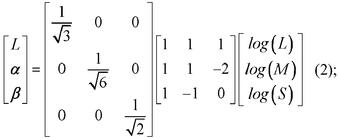
- in formula (2), L, M and S represent values of the LMS color space; and L, α and β represent values of the Lαβ color space. Here, the logarithm of the color components of the channels in the LMS color space is found respectively in order to converge data and make color distribution more in line with the perception of human eyes.
- Here, based on the orthogonality of the color space, the three channels of the color image (original image) can be separated, and the color image can be converted to the LMS color space, and then converted to the Lαβ color space by orthogonalization and decorrelation. Then, the L, α and β channels are subjected to denoising respectively after domain conversion, and the target image in the Lαβ color space is converted into a required color space format, so that the denoised color image can be obtained. The denoising after domain conversion mainly as follows: the original image is converted from a spatial domain to a spectral domain by discrete cosine transform, adaptive Gaussian smoothing is carried out on the image converted to the spectral domain, and then inverse discrete cosine transform is carried out on the image subjected to Gaussian smoothing to obtain the denoised image. In the example of the present application, noise can be separated more effectively by using the adaptive Gaussian smoothing operation.
- In the examples of the present application, the original image may be converted from the first color space to the second color space. Since the correlation between the color components of the respective channels in the second color space of the original image is smaller than the correlation between the color components of the respective channels in the first color space, by utilizing the conversion between the color spaces, the correlation between the color components of the respective channels corresponding to the original image can be weakened, so that the channel images formed by the color components of the respective channels can be denoised respectively, and the denoising of the color components of different channels at the same time can be realized. The operation is convenient, and denoising effect can be improved, such that the quality of the finally obtained target image can be ensured.
- In some other examples, after the target image is obtained, since the target image is represented by the second color space, in the implementation process, the target image represented by the second color space can be converted into the target image represented by a target color space. Taking the second color space being the Lαβ color space and the target color space being the RGB color space as an example, the target image can be converted from the Lαβ color space to the LMS color space, and then converted from the LMS color space to the RGB color space.
- A formula of conversion from the Lαβ color space to the LMS color space is as follows:

- A formula of conversion from the LMS color space to the RGB color space is as follows:

- In some other examples, the target color space may include: the LMS color space, the HSV color space and the like, which is not specifically limited here.
- In some examples, denoising the channel images formed by the color components of the respective channels in the second color space respectively to obtain the denoised images corresponding to the respective channel images includes:
- converting the channel images from a spatial domain to a spectral domain respectively; and
- denoising the channel images converted to the spectral domain respectively to obtain the denoised images corresponding to the respective channel images.
- In some examples, converting the channel images from the spatial domain to the spectral domain respectively includes:
carrying out discrete cosine transform on the channel images respectively to convert the respective channel images from the spatial domain to the spectral domain. - For example, after the original image is converted to the second color space, discrete cosine transform can be carried out on the color components of the respective channels in the second color space so that the channel images formed by the color components of the respective channels can be converted from the spatial domain to the spectral domain, and Gaussian smoothing can be carried out on the channel images in the spectral domain respectively. After the Gaussian smoothing, inverse discrete cosine transform is carried out on the channel images subjected to Gaussian smoothing to obtain the denoised images corresponding to the respective channel images.
- Here, after the channel images are converted from the spatial domain to the spectral domain, a low-frequency part, an intermediate-frequency part and a high-frequency part in the respective channel images are distributed in a set order from an upper left corner to a lower right corner of the respective channel images. At the moment, adaptive Gaussian smoothing can be carried out on the respective channel images in the spectral domain, which is equivalent to carrying out different threshold limited filtrations on different spatial frequencies, for example, an adaptive threshold can be set for the high-frequency part. After Gaussian smoothing is carried out on the respective channel images, inverse discrete cosine transform is carried out on the channel images subjected to Gaussian smoothing to obtain the denoised images corresponding to the respective channel images.
- Taking a single-channel image converted to the second color space (for example, the Lαβ color space) being O(r,θ) as an example, the distribution of the spectral domain after the adaptive Gaussian smoothing is:

- The single-channel image may be any channel image in the second color space. Taking the second color space being the Lαβ color space as an example, the single-channel image may be any of an L channel image, a α channel image and a β channel image.
- A denoised single-channel image is:

- in formula (6), O'(r,θ) represents the denoised single-channel image; T(ρ,ϕ) represents distribution of the spectral domain of the single-channel image subjected to adaptive Gaussian smoothing; and D -1[ ] represents an inverse discrete cosine transform function.
- In the example of the present application, after the respective channel images are converted from the spatial domain to the spectral domain, the channel images converted to the spectral domain are denoised respectively. Based on denoising after domain conversion, the discrete cosine transform and the Gaussian smoothing of the spectral domain are used to denoise the channel images respectively, so that a good denoising effect can be realized.
- In some examples, obtaining the target image based on the denoised images includes:
- fusing a first channel image in all the channel images and a first denoised image corresponding to the first channel image to obtain a composite image; and
- the target image is obtained based on the composite image and a second denoised image corresponding to a second channel image other than the first channel image.
- In the example of the present application, after the first channel image is denoised, the first channel image and the first denoised image corresponding to the first channel image can be fused to obtain the composite image. Taking the second color space being the Lαβ color space as an example, the first channel image may be the L channel image; and the second channel image may include the α channel image and the β channel image. That is, in an implementation process, the original L channel image and the denoised image of the L channel image can be fused to obtain the composite image.
- In the example of the present application, the fusing process may be as follows: color components for forming the composite image is obtained by means of summing and averaging the respective color components in the first channel image and the respective color components in the first denoised image, so that the composite image is obtained. In other optional examples, the first channel image and the first denoised image may also be fused based on other manners, which are not specifically limited here.
- After the composite image is obtained, the target image may be obtained based on the composite image and the second denoised image corresponding to the second channel image other than the first channel image. For example, the color components of the composite image and the color components of the second denoised image may be used as the color components of the respective channels of the target image respectively.
- Still taking the second color space being the Lαβ color space as an example, the color components of the composite image may be determined as the color components of the L channel, the color components of the first denoised image may be determined as the color components of the α channel, and the color components of the second denoised image may be determined as the color components of the β channel.
- In the example of the present application, after the first channel image and the first denoised image are fused to obtain the composite image, the target image is obtained based on the composite image and the second denoised image corresponding to the second channel image other than the first channel image, so that the obtained target image is more natural and more in line with the perception of human eyes.
- In some other examples, a number of the first channel images may be at least one, a number of the second channel images may also be at least one, and here, the number of the first channel images and the number of the second channel images may be the same or different. For example, the number of the first channel images may be one, and the number of the second channel images may be two. For another example, the number of the first channel images may be two, and the number of the second channel images may be one. For still another example, the number of the first channel images and the number of the second channel images are both one, which will not be illustrated one by one here.
- In some other examples, after the composite image is obtained, image quality parameters of the composite image may be determined, and whether the image quality parameters are greater than preset standard quality parameters may be determined. When the image quality parameters of the composite image are greater than the standard quality parameters, the target image is obtained based on the composite image and the second denoised image corresponding to the second channel image other than the first channel image. By limiting the quality parameters, the quality of the finally obtained target image can be ensured.
- In some other examples, the image quality parameters may include: image luminance, image saturation, image color, or other parameters, which are not specifically limited here. The standard quality parameters may be set according to needs, for example, may be set according to empirical values, or may also be set according to historical image parameters, or furthermore, may further be set according to user needs, which are not specifically limited here.
- In some examples, fusing the first channel image in all the channel images and the first denoised image corresponding to the first channel image to obtain the composite image includes:
- weighting color components corresponding to the first channel image and color components corresponding to the first denoised image based on composition weights to obtain a weighted color component; and
- fusing based on the weighted color component to form the composite image.
- In the example of the present application, the first channel image and the first denoised image may be weighted based on the composition weights to obtain the weighted color component, and the composite image is formed based on the weighted color component.
- Here, the original image of the first channel (first channel image) and the denoised image (first denoised image) may be composited first to obtain the composite image, and the proportions of the first channel image and the first denoised image in the composite image may be controlled by setting the composition weights, so that image details can be reserved on the basis of denoising of the composite image, such that the high-quality composite image is obtained.
- In some examples, weighting the color components corresponding to the first channel image and the color components corresponding to the first denoised image based on the composition weights to obtain the weighted color component includes:
- weighting the color components of the respective channels of the first channel image based on a first composition weight to obtain a first weighted component;
- weighting the color components of the respective channels corresponding to the first denoised image based on a second composition weight to obtain a second weighted component; and
- determining a sum of the first weighted component and the second weighted component as the weighted color component.
- Here, the first composition weight and the second composition weight may be preset, or may also be determined according to current image parameters of the first channel image and the second denoised image. For example, the current image parameters of the first channel image and the second denoised image may be acquired, and then input into a pre-trained parameter determination model to obtain corresponding first composition weight and second composition weight. The parameter determination model may be obtained by training based on a neural network model. Certainly, in other examples, the first composition weight and the second composition weight may be customized, or the first composition weight and the second composition weight may also be determined according to historical empirical values. Here, manners for determining the first composition weight and the second composition weight will not be enumerated one by one.
- In some other examples, the composite image may be expressed as:

- Still taking the second color space being the Lαβ color space as an example, in the example of the present application, the original image of the first channel (first channel image) and the denoised image (first denoised image) may be composited first to obtain the composite image, and the proportions of the first channel image and the first denoised image may be controlled by setting coefficients (the first composition weight and the second composition weight), so that image details can be reserved on the basis of denoising of the composite image, such that the high-quality composite image is obtained.
- In some other examples, the type of the first channel image may be different from the type of the second channel image. For example, the color components corresponding to the first channel image are used to represent the luminance of the original image, and the color components corresponding to the second channel image are used to represent the color of the original image. For another example, the color components corresponding to the first channel image are used to represent the color of the original image, and the color components corresponding to the second channel image are used to represent the luminance of the original image.
- In some other examples, the type of the first channel image may be the same as the type of the second channel image. For example, the color components corresponding to the first channel image and the second channel image are both used to represent the luminance of the original image; or, the color components corresponding to the first channel image and the second channel image are both used to represent the color of the original image.
- In some examples, the color components corresponding to the first channel image are used to represent the luminance of the original image. The color components corresponding to the second channel image are used to represent the color of the original image.
- In the present application, since the color components corresponding to the first channel image are used to represent the luminance of the original image and the color components corresponding to the second channel image are used to represent the color of the original image, by denoising different channel images at the same time respectively, the luminance noise and the color noise can be reduced at the same time. Compared with the original denoising method of cameras based on camera image signal processing (ISP), the image processing method adds a manner for reducing color noise, and the denoising effect is optimized and regulated by using Gaussian smoothing filtration.
-
FIG. 2 is a flow chart of another image processing method shown according to an example. As shown inFIG. 2 , the method includes the following steps: - In
step 201, an original image represented by a first color space is input. - In
step 202, the original image is converted from the first color space to a third color space. - In
step 203, the original image is converted from the third color space to a second color space. - Taking the first color space being the RGB color space, the second color space being the Lαβ color space and the third color space being the LMS color space as an example, in an implementation process, the original image can be converted from the RGB color space to the LMS color space, and then converted from the LMS color space to the Lαβ color space.
- In
step 204, discrete cosine transform is carried out on a first channel image. - Here, taking the second color space being the Lαβ color space as an example, the first channel image may be the L channel image.
- In
step 205, Gaussian smoothing is carried out on a discrete cosine transform result corresponding to the first channel image. - In
step 206, inverse discrete cosine transform is carried out on a Gaussian smoothing result corresponding to the first channel image to obtain a first denoised image. - In
step 207, the first channel image and the first denoised image are fused to obtain a composite image. - In
step 208, discrete cosine transform is carried out on a second channel image other than the first channel image. - Here, taking the second color space being the Lαβ color space as an example, the first channel image may include: the L channel image, and the second channel image may include: the α channel image and the β channel image. In some other examples, the first channel image may include: the α channel image; and the second channel image may include: the L channel image and the β channel image. In some other examples, the first channel image may include: the α channel image and the β channel image, and the second channel image may include: the L channel image. The types of the first channel image and the second channel image may be set according to needs and will not be illustrated one by one here.
- In
step 209, Gaussian smoothing is carried out on a discrete cosine transform result corresponding to the second channel image. - In
step 210, inverse discrete cosine transform is carried out on a Gaussian smoothing result corresponding to the second channel image to obtain a second denoised image. - In
step 211, a target image represented by the second color space is obtained based on the composite image and the second denoised image. - In
step 212, the target image represented by the second color space is converted into the target image represented by a target color space. - In
step 213, the target image represented by the target color space is output. - In the example of the present application, the respective channels are subjected to decorrelation by utilizing the orthogonality of the color spaces, so that the correlation between the respective channels of the image is greatly reduced, which is beneficial to the denoising effect. The original image is converted from the spatial domain to the spectral domain by discrete cosine transform, adaptive Gaussian smoothing is carried out on the image converted to the spectral domain, and then inverse discrete cosine transform is carried out on the image subjected to Gaussian smoothing to obtain the denoised image, so that a good denoising effect can be realized. By denoising different channel images at the same time respectively, the luminance noise and the color noise can be reduced at the same time. Compared with the original denoising method of cameras based on camera ISP, the image processing method adds a manner for reducing color noise, and the denoising effect can be optimized by using Gaussian smoothing filtration.
-
FIG. 3 is a block diagram of an image processing apparatus shown according to an example. As shown inFIG. 3 , theapparatus 300 mainly includes: - a
conversion module 301, configured to convert an original image represented by a first color space into the original image represented by a second color space, where a correlation between color components of respective channels in the second color space of the original image is smaller than a correlation between color components of respective channels in the first color space; - a
denoising module 302, configured to denoise channel images formed by the color components of the respective channels in the second color space respectively to obtain denoised images corresponding to the respective channel images; and - an
acquisition module 303, configured to obtain a target image based on the denoised images. - In some examples, the
acquisition module 303 is configured to: - fuse a first channel image in all the channel images and a first denoised image corresponding to the first channel image to obtain a composite image; and
- obtain the target image based on the composite image and a second denoised image corresponding to a second channel image other than the first channel image.
- In some examples, the
acquisition module 303 is configured to: - weight color components corresponding to the first channel image and color components corresponding to the first denoised image based on composition weights to obtain a weighted color component; and
- fusing based on the weighted color component to form the composite image.
- In some examples, the
acquisition module 303 is configured to: - weight the color components of the respective channels corresponding to the first channel image based on a first composition weight to obtain a first weighted component;
- weight the color components of the respective channels corresponding to the first denoised image based on a second composition weight to obtain a second weighted component; and
- determine a sum of the first weighted component and the second weighted component as the weighted color component.
- In some examples, the
denoising module 302 is configured to: - convert the channel images from a spatial domain to a spectral domain respectively; and
- denoise the channel images converted to the spectral domain respectively to obtain the denoised images corresponding to the respective channel images.
- In some examples, the denoising module is configured to:
- carry out discrete cosine transform on the channel images respectively to convert the respective channel images from the spatial domain to the spectral domain.
- In some examples, the color components corresponding to the first channel image are used to represent the luminance of the original image. The color components corresponding to the second channel image are used to represent the color of the original image.
- For the apparatus in the above examples, the specific manner in which each module executes the operation has been described in detail in the examples related to the method, and the detailed description will not be provided here.
-
FIG. 4 is a block diagram of anapparatus 1200 for image processing shown according to an example. For example, theapparatus 1200 may be a mobile phone, a computer, a digital broadcasting terminal, a message transceiving device, a game console, a tablet device, a medical device, a fitness device, a personal digital assistant or the like. - Referring to
FIG. 4 , theapparatus 1200 may include one or more of the following components: aprocessing component 1202, amemory 1204, anelectrical component 1206, amultimedia component 1208, anaudio component 1210, an input/output (I/O)interface 1212, asensor component 1214 and acommunication component 1216. - The
processing component 1202 generally controls overall operations of theapparatus 1200, such as operations associated with display, telephone calls, data communication, camera operations and recording operations. Theprocessing component 1202 may include one ormore processors 1220 to execute instructions to complete all or part of the steps of the above method. In addition, theprocessing component 1202 may include one or more modules to facilitate the interaction between theprocessing component 1202 and other components. For example, theprocessing component 1202 may include a multimedia module to facilitate the interaction between themultimedia component 1208 and theprocessing component 1202. - The
memory 1204 is configured to store various types of data to support operations in theapparatus 1200. Examples of these data include instructions for any application or method operating on theapparatus 1200, contact data, phone book data, messages, pictures, videos and the like. Thememory 1204 may be implemented by any type of volatile or non-volatile storage device or a combination of them, such as a static random access memory (SRAM), an electrically erasable programmable read-only memory (EEPROM), an erasable programmable read-only memory (EPROM), a programmable read-only memory (PROM), a read-only memory (ROM), a magnetic memory, a flash memory, a magnetic disk or an optical disk. - The
electrical component 1206 provides electric power to various components of theapparatus 1200. Theelectrical component 1206 may include a power supply management system, one or more power supplies, and other components associated with generation, management and distribution of power for theapparatus 1200. - The
multimedia component 1208 includes a screen that provides an output interface between theapparatus 1200 and the user. In some examples, the screen may include a liquid crystal display (LCD) and a touch panel (TP). If the screen includes the touch panel, the screen may be implemented as a touch screen to receive input signals from the user. The touch panel includes one or more touch sensors to sense touch, slide and gestures on the touch panel. The touch sensor may sense the boundary of a touch or slide operation, and also detect the duration and pressure related to the touch or slide operation. In some examples, themultimedia component 1208 includes a front camera and/or a rear camera. When theapparatus 1200 is in an operation mode, such as a shooting mode or a video mode, the front camera and/or the rear camera can receive external multimedia data. Each of the front camera and the rear camera may be a fixed optical lens system or have focal length and optical zoom capabilities. - The
audio component 1210 is configured to output and/or input audio signals. For example, theaudio component 1210 includes a microphone (MIC). When theapparatus 1200 is in an operation mode, such as a call mode, a recording mode and a voice recognition mode, the microphone is configured to receive an external audio signal. The received audio signal may be further stored in thememory 1204 or transmitted via thecommunication component 1216. In some examples, theaudio component 1210 further includes a speaker for outputting audio signals. - The I/
O interface 1212 provides an interface between theprocessing component 1202 and a peripheral interface module. The above peripheral interface module may be a keyboard, a click wheel, buttons and the like. These buttons may include, but are not limited to: a home button, a volume button, a start button and a lock button. - The
sensor component 1214 includes one or more sensors for providing various aspects of state evaluation to theapparatus 1200. For example, thesensor component 1214 may detect an on/off state of theapparatus 1200 and the relative positioning of the components. For example, the components are a display and a keypad of theapparatus 1200. Thesensor component 1214 may also detect the position change of theapparatus 1200 or a component of theapparatus 1200, the presence or absence of contact between a user and theapparatus 1200, the orientation or acceleration/deceleration of theapparatus 1200, and the temperature change of theapparatus 1200. Thesensor component 1214 may include a proximity sensor configured to detect the presence of nearby objects when there is no physical contact. Thesensor component 1214 may further include a light sensor, such as a CMOS or CCD image sensor, for use in imaging application. In some examples, thesensor component 1214 may further include an acceleration sensor, a gyroscope sensor, a magnetic sensor, a pressure sensor or a temperature sensor. - The
communication component 1216 is configured to facilitate wired or wireless communication between theapparatus 1200 and other devices. Theapparatus 1200 may access a wireless network based on a communication standard, such as WiFi, 4G or 5G, or a combination of them. In an example, thecommunication component 1216 receives a broadcast signal from an external broadcast management system or broadcasts related information via a broadcast channel. In an example, thecommunication component 1216 further includes a near field communication (NFC) module to facilitate short-range communication. For example, the NFC module can be implemented based on radio frequency identification (RFID) technology, infrared data association (IrDA) technology, ultra-wideband (UWB) technology, Bluetooth (BT) technology and other technologies. - In an example, the
apparatus 1200 may be implemented by one or more application specific integrated circuits (ASICs), digital signal processors (DSPs), digital signal processing devices (DSPDs), programmable logic devices (PLDs), field programmable gate arrays (FPGAs), controllers, microcontrollers, microprocessors or other electronic elements, and is used to execute the above method. - In an example, further provided is a non-transitory computer-readable storage medium including instructions is further provided, for example, a
memory 1204 including instructions. The above instructions may be executed by theprocessor 1220 of theapparatus 1200 to complete the above method. For example, the non-transitory computer-readable storage medium may be an ROM, a random access memory (RAM), a CD-ROM, a magnetic tape, a floppy disk, an optical data storage device or the like. - Provided is a non-transitory computer-readable storage medium. When instructions in the storage medium are executed by a processor of an image processing apparatus, the image processing apparatus is capable of executing an image processing method. The method includes:
- converting an original image represented by a first color space into the original image represented by a second color space, where a correlation between color components of respective channels in the second color space of the original image is smaller than a correlation between color components of respective channels in the first color space;
- denoising channel images formed by the color components of the respective channels in the second color space respectively to obtain denoised images corresponding to the respective channel images; and obtaining a target image based on the denoised images.
-
FIG. 5 is a block diagram of anotherapparatus 1300 for image processing shown according to an example. For example, theapparatus 1300 may be provided as a server. Referring toFIG. 5 , theapparatus 1300 includes aprocessing component 1322 which further includes one or more processors, and a memory resource represented by amemory 1332, for storing instructions executable by theprocessing component 1322, such as applications. Applications stored in thememory 1332 may include one or more modules each corresponding to a set of instructions. In addition, theprocessing component 1322 is configured to execute instructions to execute the above image processing method. The method includes: - converting an original image represented by a first color space into the original image represented by a second color space, where a correlation between color components of respective channels in the second color space of the original image is smaller than a correlation between color components of respective channels in the first color space;
- denoising channel images formed by the color components of the respective channels in the second color space respectively to obtain denoised images corresponding to the respective channel images; and obtaining a target image based on the denoised images.
- The
apparatus 1300 may further include apower supply component 1326 configured to execute power supply management of theapparatus 1300, a wired orwireless network interface 1350 configured to connect theapparatus 1300 to the network, and an input/output (I/O)interface 1358. Theapparatus 1300 can operate based on an operating system stored in thememory 1332, for example, Windows Server™, Mac OS X™, Unix™, Linux™, FreeBSD™ or the like. - Those skilled in the art will easily think of other implementation solutions of the present application after considering the description and practicing the present application disclosed herein. The present application is intended to cover any variations, uses or adaptive changes of the present application. These variations, uses or adaptive changes follow the general principles of the present application and include common knowledge or conventional technical means in the technical field that are not disclosed in the present application. The description and the examples are regarded to be exemplary, and the true scope of the present application are defined by the following claims.
- It should be understood that the present application is not limited to the precise structure that has been described above and shown in the accompanying drawings, and various modifications and changes can be made without departing from its scope. The scope of the present application is limited by the appended claims.
Claims (14)
- An image processing method, comprising:converting (101) an original image represented by a first color space into the original image represented by a second color space, wherein a correlation between color components of respective channels in the second color space of the original image is smaller than a correlation between color components of respective channels in the first color space; anddenoising (102) channel images formed by the color components of the respective channels in the second color space respectively to obtain denoised images corresponding to the respective channel images; andobtaining (103) a target image based on the denoised images.
- The method according to claim 1, wherein obtaining (103) the target image based on the denoised images comprises:fusing (207) a first channel image in all the channel images and a first denoised image corresponding to the first channel image to obtain a composite image; andobtaining (211) the target image based on the composite image and a second denoised image corresponding to a second channel image other than the first channel image.
- The method according to claim 2, wherein fusing (207) the first channel image in all the channel images and the first denoised image corresponding to the first channel image to obtain the composite image comprises:weighting color components corresponding to the first channel image and color components corresponding to the first denoised image based on composition weights to obtain a weighted color component; andfusing based on the weighted color component to form the composite image.
- The method according to claim 3, wherein weighting the color components corresponding to the first channel image and the color components corresponding to the first denoised image based on the composition weights to obtain the weighted color component comprises:weighting the color components of the respective channels of the first channel image based on a first composition weight to obtain a first weighted component;weighting the color components of the respective channels corresponding to the first denoised image based on a second composition weight to obtain a second weighted component; anddetermining a sum of the first weighted component and the second weighted component as the weighted color component.
- The method according to any of claims 1 to 4, wherein denoising (102) the channel images formed by the color components of the respective channels in the second color space respectively to obtain the denoised images corresponding to the respective channel images comprises:converting the channel images from a spatial domain to a spectral domain respectively; anddenoising the channel images converted to the spectral domain respectively to obtain the denoised images corresponding to the respective channel images;preferably, converting the channel images from the spatial domain to the spectral domain respectively comprises:
carrying out (204, 208) discrete cosine transform on the channel images respectively to convert the respective channel images from the spatial domain to the spectral domain. - The method according to any of claims 2 to 5, wherein the color components corresponding to the first channel image are used to represent luminance of the original image; and
the color components corresponding to the second channel image are used to represent color of the original image. - An image processing apparatus (1200, 1300), comprising:a processor (1220); anda memory (1204, 1332) storing executable instructions of the processor (1220);wherein the processor (1220):converts an original image represented by a first color space into the original image represented by a second color space, wherein a correlation between color components of respective channels in the second color space of the original image is smaller than a correlation between color components of respective channels in the first color space; anddenoises channel images formed by the color components of the respective channels in the second color space respectively to obtain denoised images corresponding to the respective channel images; andobtains a target image based on the denoised images.
- The image processing apparatus (1200, 1300) according to claim 7, wherein the processor (1220):fuses a first channel image in all the channel images and a first denoised image corresponding to the first channel image to obtain a composite image; andobtains the target image based on the composite image and a second denoised image corresponding to a second channel image other than the first channel image.
- The image processing apparatus (1200, 1300) according to claim 8, wherein the processor (1220):weights color components corresponding to the first channel image and color components corresponding to the first denoised image based on composition weights to obtain a weighted color component; andfusing based on the weighted color component to form the composite image.
- The image processing apparatus (1200, 1300) according to claim 9, wherein the processor (1220):weights the color components of the respective channels of the first channel image based on a first composition weight to obtain a first weighted component;weights the color components of the respective channels corresponding to the first denoised image based on a second composition weight to obtain a second weighted component; anddetermines a sum of the first weighted component and the second weighted component as the weighted color component.
- The image processing apparatus (1200, 1300) according to any of claims 7-10, wherein the processor (1220):converts the channel images from a spatial domain to a spectral domain respectively; anddenoises the channel images converted to the spectral domain respectively to obtain the denoised images corresponding to the respective channel images;preferably, the processor (1220):
carries out discrete cosine transform on the channel images respectively to convert the respective channel images from the spatial domain to the spectral domain. - The image processing apparatus (1200, 1300) according to any of claims 8 to 11, wherein the color components corresponding to the first channel image are used to represent luminance of the original image; and
the color components corresponding to the second channel image are used to represent color of the original image. - A non-transitory computer-readable storage medium, wherein when instructions in the storage medium are executed by a processor of an image processing apparatus, the apparatus implements the image processing method according to any of claims 1 to 6.
- A computer program product, comprising a computer program executable by a programmable device, wherein the computer program has code portions implementing the image processing method according to any of claims 1 to 6 when executed by the programmable device.
Applications Claiming Priority (1)
| Application Number | Priority Date | Filing Date | Title |
|---|---|---|---|
| CN202110540203.XA CN115375553A (en) | 2021-05-18 | 2021-05-18 | Image processing method, device and storage medium |
Publications (2)
| Publication Number | Publication Date |
|---|---|
| EP4092615A1 true EP4092615A1 (en) | 2022-11-23 |
| EP4092615B1 EP4092615B1 (en) | 2025-04-02 |
Family
ID=79171052
Family Applications (1)
| Application Number | Title | Priority Date | Filing Date |
|---|---|---|---|
| EP21218062.4A Active EP4092615B1 (en) | 2021-05-18 | 2021-12-29 | Image processing method and apparatus and storage medium |
Country Status (3)
| Country | Link |
|---|---|
| US (1) | US12260524B2 (en) |
| EP (1) | EP4092615B1 (en) |
| CN (1) | CN115375553A (en) |
Families Citing this family (1)
| Publication number | Priority date | Publication date | Assignee | Title |
|---|---|---|---|---|
| TWI779900B (en) * | 2021-10-25 | 2022-10-01 | 瑞昱半導體股份有限公司 | Image processing system and related image processing method for image enhancement based on region control and multiple processing branch |
Citations (1)
| Publication number | Priority date | Publication date | Assignee | Title |
|---|---|---|---|---|
| US20090285480A1 (en) * | 2008-05-15 | 2009-11-19 | Microsoft Corporation | Multi-channel edge-aware chrominance noise reduction |
Family Cites Families (5)
| Publication number | Priority date | Publication date | Assignee | Title |
|---|---|---|---|---|
| US8879841B2 (en) * | 2011-03-01 | 2014-11-04 | Fotonation Limited | Anisotropic denoising method |
| CN104486607B (en) * | 2014-12-31 | 2016-08-24 | 上海富瀚微电子股份有限公司 | A kind of method and device of image chroma noise reduction |
| CN104978720A (en) * | 2015-07-01 | 2015-10-14 | 深圳先进技术研究院 | Video image raindrop removal method and apparatus |
| CN109389560B (en) * | 2018-09-27 | 2022-07-01 | 深圳开阳电子股份有限公司 | Adaptive weighted filtering image noise reduction method and device and image processing equipment |
| CN109886885B (en) * | 2019-01-23 | 2021-03-02 | 齐鲁工业大学 | An image enhancement method and system based on Lab color space and Retinex |
-
2021
- 2021-05-18 CN CN202110540203.XA patent/CN115375553A/en active Pending
- 2021-12-29 EP EP21218062.4A patent/EP4092615B1/en active Active
- 2021-12-30 US US17/565,753 patent/US12260524B2/en active Active
Patent Citations (1)
| Publication number | Priority date | Publication date | Assignee | Title |
|---|---|---|---|---|
| US20090285480A1 (en) * | 2008-05-15 | 2009-11-19 | Microsoft Corporation | Multi-channel edge-aware chrominance noise reduction |
Non-Patent Citations (2)
| Title |
|---|
| GUOSHEN YU ET AL: "DCT image denoising: a simple and effective image denoising algorithm", IMAGE PROCESSING ON LINE, vol. 1, 24 October 2011 (2011-10-24), XP055551468, DOI: 10.5201/ipol.2011.ys-dct * |
| NAI-XIONG LIAN ET AL: "Image Denoising Using Optimal Color Space Projection", ACOUSTICS, SPEECH AND SIGNAL PROCESSING, 2006. ICASSP 2006 PROCEEDINGS . 2006 IEEE INTERNATIONAL CONFERENCE ON TOULOUSE, FRANCE 14-19 MAY 2006, PISCATAWAY, NJ, USA,IEEE, PISCATAWAY, NJ, USA, 2006, pages II-93 - II-96, XP031100547, ISBN: 978-1-4244-0469-8, DOI: 10.1109/ICASSP.2006.1660287 * |
Also Published As
| Publication number | Publication date |
|---|---|
| CN115375553A (en) | 2022-11-22 |
| US12260524B2 (en) | 2025-03-25 |
| EP4092615B1 (en) | 2025-04-02 |
| US20220375037A1 (en) | 2022-11-24 |
Similar Documents
| Publication | Publication Date | Title |
|---|---|---|
| US11475243B2 (en) | Training method and device for an image enhancement model, and storage medium | |
| US12254544B2 (en) | Image-text fusion method and apparatus, and electronic device | |
| WO2020093837A1 (en) | Method for detecting key points in human skeleton, apparatus, electronic device, and storage medium | |
| KR101649596B1 (en) | Method, apparatus, program, and recording medium for skin color adjustment | |
| US11989863B2 (en) | Method and device for processing image, and storage medium | |
| US20230009389A1 (en) | One-hand operation method and electronic device | |
| EP4148731B1 (en) | Audio processing method and electronic device | |
| CN110069974B (en) | Highlight image processing method and device and electronic equipment | |
| CN115330610B (en) | Image processing method, device, electronic device and storage medium | |
| US12250456B2 (en) | Video processing method and electronic device | |
| CN105791790A (en) | Image processing method and apparatus | |
| CN106303156A (en) | Method, application and mobile terminal to video denoising | |
| CN105635574B (en) | The treating method and apparatus of image | |
| WO2023273050A1 (en) | Living body detection method and apparatus, electronic device, and storage medium | |
| US12260524B2 (en) | Image processing method and storage medium | |
| KR101750058B1 (en) | Apparatus and method for generating high dynamic range image | |
| CN106982327A (en) | Image processing method and device | |
| US11899929B2 (en) | Method for customizing key of foldable device, device, and storage medium | |
| CN116934607A (en) | Image white balance processing method and device, electronic equipment and storage medium | |
| CN116805976A (en) | Video processing method, device and storage medium | |
| CN106023114B (en) | Image processing method and device | |
| CN116721024B (en) | Image processing method, device, electronic equipment and storage medium | |
| CN119784596A (en) | Image processing method and device, electronic device, and storage medium | |
| CN120378757A (en) | White balance processing method, white balance processing device, electronic equipment and storage medium | |
| CN120612375A (en) | Image processing method, device, and electronic device storage medium |
Legal Events
| Date | Code | Title | Description |
|---|---|---|---|
| PUAI | Public reference made under article 153(3) epc to a published international application that has entered the european phase |
Free format text: ORIGINAL CODE: 0009012 |
|
| STAA | Information on the status of an ep patent application or granted ep patent |
Free format text: STATUS: REQUEST FOR EXAMINATION WAS MADE |
|
| 17P | Request for examination filed |
Effective date: 20211229 |
|
| AK | Designated contracting states |
Kind code of ref document: A1 Designated state(s): AL AT BE BG CH CY CZ DE DK EE ES FI FR GB GR HR HU IE IS IT LI LT LU LV MC MK MT NL NO PL PT RO RS SE SI SK SM TR |
|
| RBV | Designated contracting states (corrected) |
Designated state(s): AL AT BE BG CH CY CZ DE DK EE ES FI FR GB GR HR HU IE IS IT LI LT LU LV MC MK MT NL NO PL PT RO RS SE SI SK SM TR |
|
| REG | Reference to a national code |
Ref country code: DE Ref legal event code: R079 Free format text: PREVIOUS MAIN CLASS: G06T0005000000 Ipc: G06T0005700000 Ref document number: 602021028469 Country of ref document: DE |
|
| GRAP | Despatch of communication of intention to grant a patent |
Free format text: ORIGINAL CODE: EPIDOSNIGR1 |
|
| STAA | Information on the status of an ep patent application or granted ep patent |
Free format text: STATUS: GRANT OF PATENT IS INTENDED |
|
| RIC1 | Information provided on ipc code assigned before grant |
Ipc: H04N 9/67 20060101ALI20240920BHEP Ipc: G06T 5/20 20060101ALI20240920BHEP Ipc: G06T 5/10 20060101ALI20240920BHEP Ipc: G06T 5/70 20240101AFI20240920BHEP |
|
| INTG | Intention to grant announced |
Effective date: 20241025 |
|
| P01 | Opt-out of the competence of the unified patent court (upc) registered |
Free format text: CASE NUMBER: APP_2494/2025 Effective date: 20250115 |
|
| GRAS | Grant fee paid |
Free format text: ORIGINAL CODE: EPIDOSNIGR3 |
|
| GRAA | (expected) grant |
Free format text: ORIGINAL CODE: 0009210 |
|
| STAA | Information on the status of an ep patent application or granted ep patent |
Free format text: STATUS: THE PATENT HAS BEEN GRANTED |
|
| AK | Designated contracting states |
Kind code of ref document: B1 Designated state(s): AL AT BE BG CH CY CZ DE DK EE ES FI FR GB GR HR HU IE IS IT LI LT LU LV MC MK MT NL NO PL PT RO RS SE SI SK SM TR |
|
| REG | Reference to a national code |
Ref country code: GB Ref legal event code: FG4D |
|
| REG | Reference to a national code |
Ref country code: CH Ref legal event code: EP |
|
| REG | Reference to a national code |
Ref country code: IE Ref legal event code: FG4D |
|
| REG | Reference to a national code |
Ref country code: DE Ref legal event code: R096 Ref document number: 602021028469 Country of ref document: DE |
|
| REG | Reference to a national code |
Ref country code: NL Ref legal event code: MP Effective date: 20250402 |
|
| PG25 | Lapsed in a contracting state [announced via postgrant information from national office to epo] |
Ref country code: NL Free format text: LAPSE BECAUSE OF FAILURE TO SUBMIT A TRANSLATION OF THE DESCRIPTION OR TO PAY THE FEE WITHIN THE PRESCRIBED TIME-LIMIT Effective date: 20250402 |
|
| REG | Reference to a national code |
Ref country code: AT Ref legal event code: MK05 Ref document number: 1782029 Country of ref document: AT Kind code of ref document: T Effective date: 20250402 |
|
| PG25 | Lapsed in a contracting state [announced via postgrant information from national office to epo] |
Ref country code: FI Free format text: LAPSE BECAUSE OF FAILURE TO SUBMIT A TRANSLATION OF THE DESCRIPTION OR TO PAY THE FEE WITHIN THE PRESCRIBED TIME-LIMIT Effective date: 20250402 Ref country code: ES Free format text: LAPSE BECAUSE OF FAILURE TO SUBMIT A TRANSLATION OF THE DESCRIPTION OR TO PAY THE FEE WITHIN THE PRESCRIBED TIME-LIMIT Effective date: 20250402 Ref country code: PT Free format text: LAPSE BECAUSE OF FAILURE TO SUBMIT A TRANSLATION OF THE DESCRIPTION OR TO PAY THE FEE WITHIN THE PRESCRIBED TIME-LIMIT Effective date: 20250804 |
|
| REG | Reference to a national code |
Ref country code: LT Ref legal event code: MG9D |
|
| PG25 | Lapsed in a contracting state [announced via postgrant information from national office to epo] |
Ref country code: NO Free format text: LAPSE BECAUSE OF FAILURE TO SUBMIT A TRANSLATION OF THE DESCRIPTION OR TO PAY THE FEE WITHIN THE PRESCRIBED TIME-LIMIT Effective date: 20250702 Ref country code: GR Free format text: LAPSE BECAUSE OF FAILURE TO SUBMIT A TRANSLATION OF THE DESCRIPTION OR TO PAY THE FEE WITHIN THE PRESCRIBED TIME-LIMIT Effective date: 20250703 |
|
| PG25 | Lapsed in a contracting state [announced via postgrant information from national office to epo] |
Ref country code: PL Free format text: LAPSE BECAUSE OF FAILURE TO SUBMIT A TRANSLATION OF THE DESCRIPTION OR TO PAY THE FEE WITHIN THE PRESCRIBED TIME-LIMIT Effective date: 20250402 |
|
| PG25 | Lapsed in a contracting state [announced via postgrant information from national office to epo] |
Ref country code: BG Free format text: LAPSE BECAUSE OF FAILURE TO SUBMIT A TRANSLATION OF THE DESCRIPTION OR TO PAY THE FEE WITHIN THE PRESCRIBED TIME-LIMIT Effective date: 20250402 |
|
| PG25 | Lapsed in a contracting state [announced via postgrant information from national office to epo] |
Ref country code: HR Free format text: LAPSE BECAUSE OF FAILURE TO SUBMIT A TRANSLATION OF THE DESCRIPTION OR TO PAY THE FEE WITHIN THE PRESCRIBED TIME-LIMIT Effective date: 20250402 |
|
| PG25 | Lapsed in a contracting state [announced via postgrant information from national office to epo] |
Ref country code: AT Free format text: LAPSE BECAUSE OF FAILURE TO SUBMIT A TRANSLATION OF THE DESCRIPTION OR TO PAY THE FEE WITHIN THE PRESCRIBED TIME-LIMIT Effective date: 20250402 |
|
| PG25 | Lapsed in a contracting state [announced via postgrant information from national office to epo] |
Ref country code: RS Free format text: LAPSE BECAUSE OF FAILURE TO SUBMIT A TRANSLATION OF THE DESCRIPTION OR TO PAY THE FEE WITHIN THE PRESCRIBED TIME-LIMIT Effective date: 20250702 |
|
| PG25 | Lapsed in a contracting state [announced via postgrant information from national office to epo] |
Ref country code: IS Free format text: LAPSE BECAUSE OF FAILURE TO SUBMIT A TRANSLATION OF THE DESCRIPTION OR TO PAY THE FEE WITHIN THE PRESCRIBED TIME-LIMIT Effective date: 20250802 |
|
| PG25 | Lapsed in a contracting state [announced via postgrant information from national office to epo] |
Ref country code: LV Free format text: LAPSE BECAUSE OF FAILURE TO SUBMIT A TRANSLATION OF THE DESCRIPTION OR TO PAY THE FEE WITHIN THE PRESCRIBED TIME-LIMIT Effective date: 20250402 |
|
| REG | Reference to a national code |
Ref country code: DE Ref legal event code: R097 Ref document number: 602021028469 Country of ref document: DE |
|
| PGFP | Annual fee paid to national office [announced via postgrant information from national office to epo] |
Ref country code: GB Payment date: 20251127 Year of fee payment: 5 |
|
| PG25 | Lapsed in a contracting state [announced via postgrant information from national office to epo] |
Ref country code: DK Free format text: LAPSE BECAUSE OF FAILURE TO SUBMIT A TRANSLATION OF THE DESCRIPTION OR TO PAY THE FEE WITHIN THE PRESCRIBED TIME-LIMIT Effective date: 20250402 Ref country code: SM Free format text: LAPSE BECAUSE OF FAILURE TO SUBMIT A TRANSLATION OF THE DESCRIPTION OR TO PAY THE FEE WITHIN THE PRESCRIBED TIME-LIMIT Effective date: 20250402 |
|
| PG25 | Lapsed in a contracting state [announced via postgrant information from national office to epo] |
Ref country code: CZ Free format text: LAPSE BECAUSE OF FAILURE TO SUBMIT A TRANSLATION OF THE DESCRIPTION OR TO PAY THE FEE WITHIN THE PRESCRIBED TIME-LIMIT Effective date: 20250402 |
|
| PG25 | Lapsed in a contracting state [announced via postgrant information from national office to epo] |
Ref country code: EE Free format text: LAPSE BECAUSE OF FAILURE TO SUBMIT A TRANSLATION OF THE DESCRIPTION OR TO PAY THE FEE WITHIN THE PRESCRIBED TIME-LIMIT Effective date: 20250402 |
|
| PG25 | Lapsed in a contracting state [announced via postgrant information from national office to epo] |
Ref country code: SK Free format text: LAPSE BECAUSE OF FAILURE TO SUBMIT A TRANSLATION OF THE DESCRIPTION OR TO PAY THE FEE WITHIN THE PRESCRIBED TIME-LIMIT Effective date: 20250402 |
|
| PG25 | Lapsed in a contracting state [announced via postgrant information from national office to epo] |
Ref country code: IT Free format text: LAPSE BECAUSE OF FAILURE TO SUBMIT A TRANSLATION OF THE DESCRIPTION OR TO PAY THE FEE WITHIN THE PRESCRIBED TIME-LIMIT Effective date: 20250402 |
|
| PLBE | No opposition filed within time limit |
Free format text: ORIGINAL CODE: 0009261 |
|
| STAA | Information on the status of an ep patent application or granted ep patent |
Free format text: STATUS: NO OPPOSITION FILED WITHIN TIME LIMIT |
|
| PG25 | Lapsed in a contracting state [announced via postgrant information from national office to epo] |
Ref country code: RO Free format text: LAPSE BECAUSE OF FAILURE TO SUBMIT A TRANSLATION OF THE DESCRIPTION OR TO PAY THE FEE WITHIN THE PRESCRIBED TIME-LIMIT Effective date: 20250402 |
|
| REG | Reference to a national code |
Ref country code: CH Ref legal event code: L10 Free format text: ST27 STATUS EVENT CODE: U-0-0-L10-L00 (AS PROVIDED BY THE NATIONAL OFFICE) Effective date: 20260211 |
|
| 26N | No opposition filed |
Effective date: 20260105 |