EP4092439A1 - System and method for reconstruction using a high-resolution phase in magnetic resonance images - Google Patents
System and method for reconstruction using a high-resolution phase in magnetic resonance images Download PDFInfo
- Publication number
- EP4092439A1 EP4092439A1 EP22152878.9A EP22152878A EP4092439A1 EP 4092439 A1 EP4092439 A1 EP 4092439A1 EP 22152878 A EP22152878 A EP 22152878A EP 4092439 A1 EP4092439 A1 EP 4092439A1
- Authority
- EP
- European Patent Office
- Prior art keywords
- space data
- partial
- image
- phase
- space
- Prior art date
- Legal status (The legal status is an assumption and is not a legal conclusion. Google has not performed a legal analysis and makes no representation as to the accuracy of the status listed.)
- Granted
Links
Images




Classifications
-
- G—PHYSICS
- G01—MEASURING; TESTING
- G01R—MEASURING ELECTRIC VARIABLES; MEASURING MAGNETIC VARIABLES
- G01R33/00—Arrangements or instruments for measuring magnetic variables
- G01R33/20—Arrangements or instruments for measuring magnetic variables involving magnetic resonance
- G01R33/44—Arrangements or instruments for measuring magnetic variables involving magnetic resonance using nuclear magnetic resonance [NMR]
- G01R33/48—NMR imaging systems
- G01R33/54—Signal processing systems, e.g. using pulse sequences ; Generation or control of pulse sequences; Operator console
- G01R33/56—Image enhancement or correction, e.g. subtraction or averaging techniques, e.g. improvement of signal-to-noise ratio and resolution
- G01R33/561—Image enhancement or correction, e.g. subtraction or averaging techniques, e.g. improvement of signal-to-noise ratio and resolution by reduction of the scanning time, i.e. fast acquiring systems, e.g. using echo-planar pulse sequences
-
- G—PHYSICS
- G06—COMPUTING OR CALCULATING; COUNTING
- G06T—IMAGE DATA PROCESSING OR GENERATION, IN GENERAL
- G06T12/00—Tomographic reconstruction from projections
- G06T12/10—Image preprocessing, e.g. calibration, positioning of sources or scatter correction
-
- A—HUMAN NECESSITIES
- A61—MEDICAL OR VETERINARY SCIENCE; HYGIENE
- A61B—DIAGNOSIS; SURGERY; IDENTIFICATION
- A61B5/00—Measuring for diagnostic purposes; Identification of persons
- A61B5/05—Detecting, measuring or recording for diagnosis by means of electric currents or magnetic fields; Measuring using microwaves or radio waves
- A61B5/055—Detecting, measuring or recording for diagnosis by means of electric currents or magnetic fields; Measuring using microwaves or radio waves involving electronic [EMR] or nuclear [NMR] magnetic resonance, e.g. magnetic resonance imaging
-
- A—HUMAN NECESSITIES
- A61—MEDICAL OR VETERINARY SCIENCE; HYGIENE
- A61B—DIAGNOSIS; SURGERY; IDENTIFICATION
- A61B5/00—Measuring for diagnostic purposes; Identification of persons
- A61B5/72—Signal processing specially adapted for physiological signals or for diagnostic purposes
- A61B5/7235—Details of waveform analysis
- A61B5/7253—Details of waveform analysis characterised by using transforms
- A61B5/726—Details of waveform analysis characterised by using transforms using Wavelet transforms
-
- A—HUMAN NECESSITIES
- A61—MEDICAL OR VETERINARY SCIENCE; HYGIENE
- A61B—DIAGNOSIS; SURGERY; IDENTIFICATION
- A61B5/00—Measuring for diagnostic purposes; Identification of persons
- A61B5/72—Signal processing specially adapted for physiological signals or for diagnostic purposes
- A61B5/7235—Details of waveform analysis
- A61B5/7264—Classification of physiological signals or data, e.g. using neural networks, statistical classifiers, expert systems or fuzzy systems
- A61B5/7267—Classification of physiological signals or data, e.g. using neural networks, statistical classifiers, expert systems or fuzzy systems involving training the classification device
-
- G—PHYSICS
- G01—MEASURING; TESTING
- G01R—MEASURING ELECTRIC VARIABLES; MEASURING MAGNETIC VARIABLES
- G01R33/00—Arrangements or instruments for measuring magnetic variables
- G01R33/20—Arrangements or instruments for measuring magnetic variables involving magnetic resonance
- G01R33/44—Arrangements or instruments for measuring magnetic variables involving magnetic resonance using nuclear magnetic resonance [NMR]
- G01R33/46—NMR spectroscopy
- G01R33/4616—NMR spectroscopy using specific RF pulses or specific modulation schemes, e.g. stochastic excitation, adiabatic RF pulses, composite pulses, binomial pulses, Shinnar-le-Roux pulses, spectrally selective pulses not being used for spatial selection
-
- G—PHYSICS
- G01—MEASURING; TESTING
- G01R—MEASURING ELECTRIC VARIABLES; MEASURING MAGNETIC VARIABLES
- G01R33/00—Arrangements or instruments for measuring magnetic variables
- G01R33/20—Arrangements or instruments for measuring magnetic variables involving magnetic resonance
- G01R33/44—Arrangements or instruments for measuring magnetic variables involving magnetic resonance using nuclear magnetic resonance [NMR]
- G01R33/48—NMR imaging systems
- G01R33/4818—MR characterised by data acquisition along a specific k-space trajectory or by the temporal order of k-space coverage, e.g. centric or segmented coverage of k-space
-
- G—PHYSICS
- G01—MEASURING; TESTING
- G01R—MEASURING ELECTRIC VARIABLES; MEASURING MAGNETIC VARIABLES
- G01R33/00—Arrangements or instruments for measuring magnetic variables
- G01R33/20—Arrangements or instruments for measuring magnetic variables involving magnetic resonance
- G01R33/44—Arrangements or instruments for measuring magnetic variables involving magnetic resonance using nuclear magnetic resonance [NMR]
- G01R33/48—NMR imaging systems
- G01R33/54—Signal processing systems, e.g. using pulse sequences ; Generation or control of pulse sequences; Operator console
- G01R33/56—Image enhancement or correction, e.g. subtraction or averaging techniques, e.g. improvement of signal-to-noise ratio and resolution
- G01R33/5602—Image enhancement or correction, e.g. subtraction or averaging techniques, e.g. improvement of signal-to-noise ratio and resolution by filtering or weighting based on different relaxation times within the sample, e.g. T1 weighting using an inversion pulse
-
- G—PHYSICS
- G01—MEASURING; TESTING
- G01R—MEASURING ELECTRIC VARIABLES; MEASURING MAGNETIC VARIABLES
- G01R33/00—Arrangements or instruments for measuring magnetic variables
- G01R33/20—Arrangements or instruments for measuring magnetic variables involving magnetic resonance
- G01R33/44—Arrangements or instruments for measuring magnetic variables involving magnetic resonance using nuclear magnetic resonance [NMR]
- G01R33/48—NMR imaging systems
- G01R33/54—Signal processing systems, e.g. using pulse sequences ; Generation or control of pulse sequences; Operator console
- G01R33/56—Image enhancement or correction, e.g. subtraction or averaging techniques, e.g. improvement of signal-to-noise ratio and resolution
- G01R33/5608—Data processing and visualization specially adapted for MR, e.g. for feature analysis and pattern recognition on the basis of measured MR data, segmentation of measured MR data, edge contour detection on the basis of measured MR data, for enhancing measured MR data in terms of signal-to-noise ratio by means of noise filtering or apodization, for enhancing measured MR data in terms of resolution by means for deblurring, windowing, zero filling, or generation of gray-scaled images, colour-coded images or images displaying vectors instead of pixels
-
- G—PHYSICS
- G06—COMPUTING OR CALCULATING; COUNTING
- G06T—IMAGE DATA PROCESSING OR GENERATION, IN GENERAL
- G06T7/00—Image analysis
- G06T7/0002—Inspection of images, e.g. flaw detection
-
- G—PHYSICS
- G01—MEASURING; TESTING
- G01R—MEASURING ELECTRIC VARIABLES; MEASURING MAGNETIC VARIABLES
- G01R33/00—Arrangements or instruments for measuring magnetic variables
- G01R33/20—Arrangements or instruments for measuring magnetic variables involving magnetic resonance
- G01R33/44—Arrangements or instruments for measuring magnetic variables involving magnetic resonance using nuclear magnetic resonance [NMR]
- G01R33/48—NMR imaging systems
- G01R33/4818—MR characterised by data acquisition along a specific k-space trajectory or by the temporal order of k-space coverage, e.g. centric or segmented coverage of k-space
- G01R33/4824—MR characterised by data acquisition along a specific k-space trajectory or by the temporal order of k-space coverage, e.g. centric or segmented coverage of k-space using a non-Cartesian trajectory
-
- G—PHYSICS
- G06—COMPUTING OR CALCULATING; COUNTING
- G06T—IMAGE DATA PROCESSING OR GENERATION, IN GENERAL
- G06T2207/00—Indexing scheme for image analysis or image enhancement
- G06T2207/10—Image acquisition modality
- G06T2207/10072—Tomographic images
- G06T2207/10088—Magnetic resonance imaging [MRI]
Definitions
- the field of the disclosure relates generally to systems and methods of magnetic resonance imaging (MRI), and more particularly, to techniques of image reconstruction in MRI.
- MRI magnetic resonance imaging
- MRI has proven useful in diagnosis of many diseases. MRI provides detailed images of soft tissues, abnormal tissues such as tumors, and other structures, which cannot be readily imaged by other imaging modalities, such as computed tomography (CT). Further, MRI operates without exposing patients to ionizing radiation experienced in modalities such as CT and x-rays.
- CT computed tomography
- the MR signals acquired with an MRI system are signal samples of the subject of the examination in Fourier space, or what is often referred to in the art as "k-space".
- k-space a partial k-space is often sampled in order to increase the efficiency of the acquisition and/or to suppress artifacts.
- Reconstructing a partially-sampled k-space dataset results in an image that is contaminated by truncation artifacts in the form of both blurring and a characteristic ringing that severely degrades the diagnostic value of the MR image.
- a method for producing an image of a subject with a magnetic resonance imaging (MRI) system includes acquiring, a first set of partial k-space data from the subject and generating a phase corrected image based on a phase correction factor and the first set of the partial k-space data.
- the method further includes transforming the phase corrected image into a second set of partial k-space data and reconstructing the image of the subject from the second set of the partial k-space data and a weighting function.
- a magnetic resonance imaging (MRI) system includes a magnet configured to generate a polarizing magnetic field about at least a portion of a subject arranged in the MRI system and a gradient coil assembly including a plurality of gradient coils configured to apply at least one gradient field to the polarizing magnetic field.
- the MRI system also includes a radio frequency (RF) system configured to apply an RF field to the subject and to receive magnetic resonance signals from the subject.
- the MRI system further includes a processing system programmed to acquire a first set of partial k-space data from the subject.
- the processing system is also programmed to generate a phase corrected image based on a phase correction factor and the first set of the partial k-space data and transform the phase corrected image into a second set of partial k-space data.
- the processing system is further programmed to reconstruct the image of the subject from the second set of the partial k-space data and a weighting function.
- a method of MR imaging includes acquiring a first set of k-space data for less than all of k-space from a subject and reconstructing the k-space data into a crude image.
- the method also includes generating a phase corrected image based on a phase correction factor and the first set of k-space data and transforming the phase corrected image into a second set of k-space data.
- the method further includes reconstructing, from the second set of the k-space data and a weighting function, the image of the subj ect.
- circuit and “circuitry” and “controller” may include either a single component or a plurality of components, which are either active and/or passive and are connected or otherwise coupled together to provide the described function.
- MRI magnetic resonance imaging
- an obj ect is placed in a magnet.
- magnetic moments of nuclei such as protons, attempt to align with the magnetic field but process about the magnetic field in a random order at the nuclei's Larmor frequency.
- the magnetic field of the magnet is referred to as B0 and extends in the longitudinal or z direction.
- a magnetic field (referred to as an excitation field B1), which is in the x-y plane and near the Larmor frequency, is generated by a radio-frequency (RF) coil and may be used to rotate, or "tip," the net magnetic moment M z of the nuclei from the z direction to the transverse or x-y plane.
- RF radio-frequency
- a signal which is referred to as a MR signal, is emitted by the nuclei, after the excitation signal B1 is terminated.
- magnetic field gradient pulses G x , G y , and G z
- the gradient pulses are used to scan through the k space, the space of spatial frequencies or inverse of distances.
- a Fourier relationship exists between the acquired MR signals and an image of the object, and therefore the image of the object can be derived by reconstructing the MR signals.
- the images of the object may include two dimensional (2D) or three-dimensional (3D) images.
- FIG. 1 is a schematic diagram of a magnetic resonance imaging (MRI) system 10. Operation of the system 10 may be controlled from an operator console 12, which includes an input device 13, a control panel 14, and a display screen 16.
- the input device 13 may be a mouse, joystick, keyboard, track ball, touch activated screen, light wand, voice control, and/or other input device.
- the input device 13 may be used for interactive geometry prescription.
- the console 12 communicates through a link 18 with a computer system 20 that enables an operator to control the production and display of images on the display screen 16.
- the link 18 may be a wireless or wired connection.
- the computer system 20 may include modules that communicate with each other through a backplane 20a.
- the modules of the computer system 20 may include an image processor module 22, a central processing unit (CPU) module 24, and a memory module 26 that may include a frame buffer for storing image data arrays, for example.
- the computer system 20 may be linked to archival media devices, permanent or back-up memory storage or a network for storage of image data and programs and communicates with MRI system control 32 through a high-speed signal link 34.
- the MRI system control 32 may be separate from or integral with the computer system 20.
- the computer system 20 and the MRI system control 32 collectively form an "MRI controller" 33 or "controller".
- the MRI system control 32 includes modules connected by a backplane 32a. These modules include a CPU module 36 as well as a pulse generator module 38.
- the CPU module 36 connects to the operator console 12 through a data link 40.
- the MRI system control 32 receives commands from the operator through the data link 40 to indicate the scan sequence that is to be performed.
- the CPU module 36 operates the system components to carry out the desired scan sequence and produces data which indicates the timing, strength and shape of the RF pulses produced, and the timing and length of the data acquisition window.
- the CPU module 36 connects to components that are operated by the MRI controller 32, including the pulse generator module 38 which controls a gradient amplifier 42, a physiological acquisition controller (PAC) 44, and a scan room interface circuit 46.
- PAC physiological acquisition controller
- the CPU module 36 receives patient data from the physiological acquisition controller 44, which receives signals from sensors connected to the subject, such as ECG signals received from electrodes attached to the patient.
- the CPU module 36 receives, via the scan room interface circuit 46, signals from the sensors associated with the condition of the patient and the magnet system.
- the scan room interface circuit 46 also enables the MRI controller 33 to command a patient positioning system 48 to move the patient to a desired position for scanning.
- a whole-body RF coil 56 is used for transmitting the waveform towards subject anatomy.
- the whole body-RF coil 56 may be a body coil.
- An RF coil may also be a local coil that may be placed in more proximity to the subject anatomy than a body coil.
- the RF coil 56 may also be a surface coil.
- RF coils containing RF receiver channels may be used for receiving the signals from the subject anatomy. Typical surface coil would have eight receiving channels; however, different number of channels are possible. Using the combination of both a body coil 56 and a surface coil is known to provide better image quality.
- the pulse generator module 38 may operate the gradient amplifiers 42 to achieve desired timing and shape of the gradient pulses that are produced during the scan.
- the gradient waveforms produced by the pulse generator module 38 may be applied to the gradient amplifier system 42 having Gx, Gy, and Gz amplifiers.
- Each gradient amplifier excites a corresponding physical gradient coil in a gradient coil assembly 50, to produce the magnetic field gradients used for spatially encoding acquired signals.
- Gx corresponds to a flow/frequency encoding gradient
- Gy corresponds to a phase encoding gradient
- Gz corresponds to a slice select gradient.
- the gradient coil assembly 50 may form part of a magnet assembly 52, which also includes a polarizing magnet 54 (which, in operation, provides a longitudinal magnetic field B 0 throughout a target volume 55 that is enclosed by the magnet assembly 52 and a whole-body RF coil 56 (which, in operation, provides a transverse magnetic field B1 that is generally perpendicular to B0 throughout the target volume 55.
- a transceiver module 58 in the MRI system control 32 produces pulses that may be amplified by an RF amplifier 60 and coupled to the RF coil 56 by a transmit/receive switch 62.
- the resulting signals emitted by the excited nuclei in the subject anatomy may be sensed by receiving coils (not shown) and provided to a preamplifier 64 through the transmit/receive switch 62.
- the amplified MR signals are demodulated, filtered, and digitized in the receiver section of the transceiver 58.
- the transmit/receive switch 62 is controlled by a signal from the pulse generator module 38 to electrically connect the RF amplifier 60 to the coil 56 during the transmit mode and to connect the preamplifier 64 to the receiving coil during the receive mode.
- Computer readable media may include, for example, structures configured so that electrical, optical, or magnetic states may be fixed in a manner perceptible and reproducible by a conventional computer (e.g., text or images printed to paper or displayed on a screen, optical discs, or other optical storage media, "flash” memory, EEPROM, SDRAM, or other electrical storage media; floppy or other magnetic discs, magnetic tape, or other magnetic storage media).
- a scan is complete when an array of raw k-space data has been acquired in the computer readable media 66.
- This raw k-space data is rearranged into separate k-space data arrays for each image to be reconstructed, and each of these k-space data arrays is input to an array processor 68, which operates to reconstruct the data into an array of image data, using a reconstruction algorithm such as a Fourier transform.
- the full k-space data is obtained, it represents entire volume of the subject body and the k-space so obtained may be referred as the reference k-space.
- the image may be referred as the partial k-space.
- This image data is conveyed through the data link 34 to the computer system 20 and stored in memory. In response to the commands received from the operator console 12, this image data may be archived in a long-term storage or may be further processed by the image processor 22 and conveyed to the operator console 12 and presented on the display 16.
- MR signals are represented by complex numbers, where each location at the k-space is represented by a complex number, with I and Q quadrature MR signals being the real and imaginary components.
- Complex MR images may be reconstructed based on I and Q quadrature MR signals, using processes such as Fourier transform of the k-space MR data.
- Complex MR images are MR images with each pixel represented by a complex number, which also has a real component and an imaginary component.
- asymmetric sampling in the frequency and phase encoding directions or dimensions is referred to as fractional echo and partial number of acquisition (NEX), respectively, and is widely used in both 2D and 3D MR imaging.
- NEX fractional echo and partial number of acquisition
- These undersampling techniques are typically used to shorten echo times (e.g. to increase SNR or alter tissue contrast), to shorten repetition times (e.g. to reduce scan time), and/or to suppress unwanted artifacts (such as fineline artifact in fast-spin echo (FSE) imaging or off-resonance artifacts in gradient recalled echo (GRE) and echo planar imaging (EPI)).
- FSE fast-spin echo
- GRE gradient recalled echo
- EPI echo planar imaging
- Asymmetric sampling of k-space introduces truncation artifacts into the reconstructed images, both in the form of blurring and ringing.
- phase estimate is often derived from the central, symmetrically-sampled portion of k-space, and is limited in several important ways.
- the phase estimate is contaminated by thermal noise, which is especially problematic in low-signal image regions and/or when this phase estimate performed on a per-channel (or per-view) basis.
- this phase estimate is inherently bandlimited, and must be further low-pass filtered upon application to prevent the introduction of additional truncation artifacts. Therefore, high spatial frequency phase information is not corrected, leaving residual blurring in the final reconstructed image.
- the application of this low-frequency phase estimate also tends to bias the noise in the reconstructed image, which would otherwise tend to be normally distributed.
- the appearance of this biased noise signal in the reconstructed image degrades the image contrast, especially in low-signal regions, and the altered distribution of this noise degrades noise-averaging performance (as in multi-NEX EPI-diffusion) and/or complicate downstream denoising efforts, which are generally based on an assumed noise model.
- phase information is discarded during reconstruction, making them unsuitable for phase-sensitive applications, such as Dixon chemical shift imaging, phase-sensitive inversion recovery imaging, and generation of phase-sensitive maps based on the phases of the images.
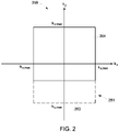
- FIG. 2 is a schematic diagram of a partial sampling pattern or truncation pattern 259 of a full k-space 261.
- a full k-space 261 is defined by the maximum kx or ky values k x , max and k y , max , which is defined by maximum frequency- or phase-encoding gradients.
- part of the high spatial frequency data 263 is not acquired.
- Truncation may be in the kx dimension and/or the ky dimension, and may be in the kz dimension in a three-dimension (3D) acquisition.
- the full k-space 261 is truncated into a partial k-space 264.
- Truncation 2 is the full k-space 261 truncated in the ky dimension, where negative high spatial frequency data are not acquired during the image acquisition of the partial k-space 264.
- Truncation may be asymmetrical, where the k-space is truncated asymmetrically in a dimension.
- the partial k-space 264 shown in FIG. 2 is asymmetrical truncated in the ky dimension.
- Truncation reduces high-spatial frequency data and causes truncation artifacts.
- Truncation along the axes of a 2D Cartesian coordinate system as shown in FIG. 2 is illustrated as an example only.
- FIG. 3 is a schematic diagram of k-space sampling patterns in accordance with an embodiment of the present technique.
- plot 352 shows a projection reconstruction acquisition
- plot 354 shows a three-dimensional Fourier transformation (3DFT) acquisition.
- 3DFT three-dimensional Fourier transformation
- the outer circles in both plots 352 and 354 relates to full acquisition/sampling or full k-space.
- plot 352 has only 2 planes k x and k y
- plot 354 has 3 planes k x , k y and k z .
- the k x plane in plot 354 corresponds to an axis that will come out of the central dot 356.
- the data that is acquired is represented by the shaded bars 360.
- the systems and methods described herein may also be used for removal of truncation artifacts in images based on k-space data from a k-space that is asymmetrically truncated along the axes of a 2D/3D Cartesian coordinate system, a 2D/3D non-Cartesian coordinate system such as a polar, spherical, or cylindrical coordinate system, or a combination thereof.
- the partial sampling pattern is the k-space being asymmetrically truncated in a radial dimension.
- the k-space data are acquired as a stack of radial lines in the kx-ky planes along the kz direction and a partial sampling pattern is the k-space being asymmetrically truncated in a radial dimension in the kx-ky plane and asymmetrically truncated in the kz dimension.
- FIG. 4 is a schematic diagram of a conventional homodyne method 100 for reconstructing partial k-space data.
- method 100 initially a partial asymmetric k-space data set M pk (k x , k y ) (102) and a central symmetric k-space data set M s (k x , k y ) (104) is generated.
- a phase correction factor needs to be applied before the k-space symmetry can be exploited to synthesize the missing data from the partial k-space data M pk (k x , k y ).
- This phase estimate is derived from the central, symmetrically-sampled k-space data M s (k x , k y ).
- the method 100 includes defining a pre-weighting function W(k y ) (106).
- the partial k-space data is then multiplied by the pre-weighting function by a multiplier block 108.
- the weighted partial k-space data from the multiplier block 108 is then inverse Fourier transformed to produce an weighted image m pk (x, y)*w(x, y) (112).
- central symmetric k-space data set M s (k x , k y ) is inverse Fourier transformed to produce the image m s (x, y) (110).
- the phase correction factor is then used to correct the weighted image by multiplying p *(x, y) with m pk (x, y)*w(x, y) by another multiplier block 114.
- a desired image 116 is then obtained by taking the real part of the result of the multiplier block 114.
- the conventional Homodyne reconstruction method uses low-resolution phase for phase correction, resulting in severe artifacts in regions with rapid phase change due to motion, chemical shift, air-tissue interfaces, etc. Therefore, the reconstruction method in the present invention derives a high-resolution denoised phase from zero-filled complex data with deep learning and/or other methods, then applies the high-resolution phase during the phase correction step to minimize these artifacts.
- high-resolution phase refers to a phase having high resolution compared to the phase determined with conventional Homodyne reconstruction method or the phase determined with centralized symmetric k-space data.
- FIG. 5 is a schematic diagram of a method 200 for reconstructing partial k-space data, in accordance with an embodiment of the present technique.
- the method 200 may also be referred to as a modified homodyne reconstruction method.
- a partial asymmetric k-space data set M(k x , k y ) i.e., a first set of partial k-space data 202 is generated.
- a crude image m z (x, y) 204 is then generated from the partial asymmetric k-space data set 202.
- the crude image 204 may be reconstructed by zero-filling the partial k-space data with zeros at locations corresponding to the skipped k-space locations to derive full k-space data, and then reconstructing the crude image based on the zero-filled k-space data.
- the full k-space data for the crude image may be reconstructed by methods other than zero-filling, such as interpolation.
- the method further includes determining a high-resolution denoised phase ⁇ p(x,y) 206.
- the high-resolution denoised phase ⁇ p(x,y) 206 is determined from the crude image 204 using deep learning (DL) techniques (e.g., a neural network 220).
- the high-resolution denoised phase 206 is determined in radians and may also be referred to as a phase correction factor.
- other denoising method 222 such as principal component analysis (PCA), Wavelet Analysis, Total Variance, etc. may also be used to generate the high-resolution denoised phase 206.
- PCA principal component analysis
- Wavelet Analysis Wavelet Analysis
- Total Variance Total Variance
- the high-resolution denoised phase 206 may be determined using an external pre-acquired high resolution image 224.
- the phase corrected image 210 is then Fourier transformed to produce a truncated phase corrected k-space data set M z * (k x , k y ), i.e., a second set of partial k-space data 212.
- the method 200 includes defining a pre-weighting function W(k y ) (214).
- the pre-weighting function is chosen to emphasize a subspace of the acquisition space or for a better reconstruction of a portion of the data.
- the pre-weighting function represents spectral sampling density.
- phase corrected k-space data set 212 is then multiplied with the pre-weighting function 214 by a multiplier block 216.
- a desired image 218 is then obtained by taking the real part of the result of the multiplier block 216.
- FIG. 6 is a schematic diagram of an exemplary neural network model 300 that may be used in the embodiment of Fig. 5 for determining high-resolution denoised phase.
- the neural network model 300 may include a convolutional neural network 302.
- the neural network 302 accepts a MR phase image 304 contaminated with corrupted phase information (i.e., a corrupted image) and returns a pristine phase image 306, where the background phase 308 has been substantially denoised.
- Inputs and outputs to the neural network 302 may also be complex images, magnitude and phase image pairs, or real or imaginary image pairs.
- the neural network 302 may trained with a loss function, which is a function measuring the inference error by the neural network 302.
- the loss function may be expressed as min(f1(input) - f2(output)), where f1 and f2 are functions of the input and the output to the neural network 302, respectively.
- the loss function includes constraints based on prior knowledge of the phase information. For example, prior knowledge is that phase aliasing or phase wrapping may be caused by the computation method of phases.
- phase sensitive imaging applications where phase is used to encode a physical phenomenon, such as flow, motion, or temperature, prior knowledge includes physical law. Phase that behaves against physical law is penalized by the loss function. For example, in flow imaging or quantitative susceptibility measurements (QSM), flow is divergence free. In thermal imaging, heat is expected to dissipate relatively uniformly. For displacement imaging such as elastography, the displacement is expected to obey physical law of motion.
- QSM quantitative susceptibility measurements
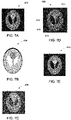
- FIGs. 7A-7E provide a comparison of k-space data reconstruction using conventional homodyne method with the modified homodyne technique presented herein.
- FIG. 7A is a phantom image 402 corresponding to a fully sampled k-space.
- FIG. 7B is a phase image 404 of the phantom image 402.
- FIG. 7C is a zero filled phantom image 406 corresponding to a partial k-space data set.
- FIG. 7D is a phantom image 408 after phase correction corresponding to a conventional homodyne method as described in Fig. 5 .
- FIG. 7E is a phase corrected phantom image 410 according to the modified homodyne technique presented herein.
- Figs. 7A-7E are simulated phantom images.
- the phantom image 408 generated with the conventional homodyne method includes artifacts 412, 414, 416 and 418 corresponding to the regions of rapid phase change. These artifacts are minimized in the phantom image 410 ( Fig. 7E ) generated with the proposed modified Homodyne reconstruction method which looks very similar to the phantom image 402 generated with fully sampled k-space.
- FIG. 8A is a simulated abdominal image 502 after phase correction corresponding to a conventional homodyne method as described in Fig. 5 .
- FIG. 8B is a phase corrected simulated abdominal image 504 according to the modified homodyne technique presented herein.
- the artifacts 506, 508, 510 corresponding to rapid phase change in Fig. 8A have been minimized to a great extent in image 504 of Fig. 8B .
- the abdominal image generated using the conventional Homodyne is quite inferior to the abdominal image of the modified Homodyne technique with high resolution phase according to an embodiment of the present technique.
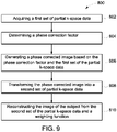
- Fig. 9 is a flow chart 800 depicting a method for producing an image of a subject with a magnetic resonance imaging (MRI) system.
- the method includes acquiring a first set of partial k-space data from the subject at step 802.
- the first set of k-space data is for less than all of k-space from the subject.
- the first set of partial k-space data include k-space data from a partial k-space that is truncated in at least one k-space dimension.
- the method includes determining a phase correction factor.
- the phase correction factor may be determined from the first set of the partial k-space data.
- a crude image is reconstructed from the first set of the partial k-space data.
- the crude image is reconstructed by zero-filling the first set of partial k-space data with zeros at locations corresponding to the skipped k-space locations to derive full k-space data, and then reconstructing the crude image based on the zero-filled k-space data.
- a neural network model a wavelet transform algorithm, a principal component analysis (PCA) algorithm or a total variance (TV) algorithm is used with the crude image to determine the phase correction factor.
- the neural network model is trained with a pair of pristine images and corrupted images, wherein the corrupted images include corrupted phase information, the pristine images are the corrupted images with the corrupted phase information reduced.
- the phase correction factor may be determined from an external image which is a pre-acquired high resolution image.
- the crude image and the phase correction factor is multiplied to generate a phase corrected image at step 806.
- the method includes transforming the phase corrected image into a second set of partial k-space data. The transformation may be performed by applying a Fast Fourier Transform (FFT) on the phase corrected image.
- FFT Fast Fourier Transform
- the method includes reconstructing the image of the subject, from the second set of the partial k-space data and a weighting function.
- the weighting function refers to spectral sampling density and may include a Hanning window function. First, the weighting function is multiplied with the second set of the partial k-space data to and then the real portion of the result is used as the desired image of the subject.
- One advantage of the present technique is that it systematically minimizes common artifacts in MRI images such as in regions with rapid phase variations and can be broadly applied to improve the image quality of out-of-phase water-fat imaging, diffusion imaging, gradient echo imaging, etc. Further, since the technique uses a partial k-space data, efficiency of the MRI acquisition is improved.
Landscapes
- Physics & Mathematics (AREA)
- Health & Medical Sciences (AREA)
- Engineering & Computer Science (AREA)
- Life Sciences & Earth Sciences (AREA)
- High Energy & Nuclear Physics (AREA)
- Nuclear Medicine, Radiotherapy & Molecular Imaging (AREA)
- General Health & Medical Sciences (AREA)
- General Physics & Mathematics (AREA)
- Condensed Matter Physics & Semiconductors (AREA)
- Radiology & Medical Imaging (AREA)
- Artificial Intelligence (AREA)
- Heart & Thoracic Surgery (AREA)
- Surgery (AREA)
- Veterinary Medicine (AREA)
- Public Health (AREA)
- Animal Behavior & Ethology (AREA)
- Signal Processing (AREA)
- Molecular Biology (AREA)
- Medical Informatics (AREA)
- Biomedical Technology (AREA)
- Pathology (AREA)
- Biophysics (AREA)
- Computer Vision & Pattern Recognition (AREA)
- Psychiatry (AREA)
- Physiology (AREA)
- Spectroscopy & Molecular Physics (AREA)
- Theoretical Computer Science (AREA)
- Mathematical Physics (AREA)
- Fuzzy Systems (AREA)
- Evolutionary Computation (AREA)
- Quality & Reliability (AREA)
- Magnetic Resonance Imaging Apparatus (AREA)
Abstract
Description
- The field of the disclosure relates generally to systems and methods of magnetic resonance imaging (MRI), and more particularly, to techniques of image reconstruction in MRI.
- MRI has proven useful in diagnosis of many diseases. MRI provides detailed images of soft tissues, abnormal tissues such as tumors, and other structures, which cannot be readily imaged by other imaging modalities, such as computed tomography (CT). Further, MRI operates without exposing patients to ionizing radiation experienced in modalities such as CT and x-rays.
- The MR signals acquired with an MRI system are signal samples of the subject of the examination in Fourier space, or what is often referred to in the art as "k-space". In MR imaging, a partial k-space is often sampled in order to increase the efficiency of the acquisition and/or to suppress artifacts. Reconstructing a partially-sampled k-space dataset results in an image that is contaminated by truncation artifacts in the form of both blurring and a characteristic ringing that severely degrades the diagnostic value of the MR image.
- Therefore, there is a need for an improved magnetic resonance imaging system and method.
- In accordance with an embodiment of the present technique, a method for producing an image of a subject with a magnetic resonance imaging (MRI) system is presented. The method includes acquiring, a first set of partial k-space data from the subject and generating a phase corrected image based on a phase correction factor and the first set of the partial k-space data. The method further includes transforming the phase corrected image into a second set of partial k-space data and reconstructing the image of the subject from the second set of the partial k-space data and a weighting function.
- In accordance with another embodiment of the present technique, a magnetic resonance imaging (MRI) system is presented. The MRI system includes a magnet configured to generate a polarizing magnetic field about at least a portion of a subject arranged in the MRI system and a gradient coil assembly including a plurality of gradient coils configured to apply at least one gradient field to the polarizing magnetic field. The MRI system also includes a radio frequency (RF) system configured to apply an RF field to the subject and to receive magnetic resonance signals from the subject. The MRI system further includes a processing system programmed to acquire a first set of partial k-space data from the subject. The processing system is also programmed to generate a phase corrected image based on a phase correction factor and the first set of the partial k-space data and transform the phase corrected image into a second set of partial k-space data. The processing system is further programmed to reconstruct the image of the subject from the second set of the partial k-space data and a weighting function.
- In accordance with yet another embodiment of the present technique, a method of MR imaging is presented. The method includes acquiring a first set of k-space data for less than all of k-space from a subject and reconstructing the k-space data into a crude image. The method also includes generating a phase corrected image based on a phase correction factor and the first set of k-space data and transforming the phase corrected image into a second set of k-space data. The method further includes reconstructing, from the second set of the k-space data and a weighting function, the image of the subj ect.
- These and other features, aspects, and advantages of the present invention will become better understood when the following detailed description is read with reference to the accompanying drawings in which like characters represent like parts throughout the drawings, wherein:
-
FIG. 1 is a schematic diagram of an exemplary magnetic resonance imaging (MRI) system; -
FIG. 2 is a schematic diagram of a partial k-space sampling, in accordance with an embodiment of the present technique; -
FIG. 3 is a schematic diagram of k-space sampling patterns, in accordance with an embodiment of the present technique; -
FIG. 4 is a schematic diagram of a conventional homodyne method for reconstructing partial k-space data; -
FIG. 5 is a schematic diagram of a method for reconstructing partial k-space data, in accordance with an embodiment of the present technique; -
FIG. 6 is an exemplary neural network model for the method shown inFIG. 5 , in accordance with an embodiment of the present technique. -
FIG. 7A is a phantom image corresponding to a fully sampled k-space data; -
FIG. 7B is a phase image of the phantom image ofFig. 7A ; -
FIG. 7C is a zero filled phantom image corresponding to a partial k-space data set; -
FIG. 7D is a phantom image after phase correction corresponding to a conventional homodyne method; -
FIG. 7E is a phase corrected phantom image according to the modified homodyne technique, in accordance with an embodiment of the present technique; -
FIG. 8A is a simulated abdominal image after phase correction corresponding to a conventional homodyne method; -
FIG. 8B is a phase corrected simulated abdominal image according to the modified homodyne technique, in accordance with an embodiment of the present technique; and -
FIG. 9 is a flow chart depicting a method for producing an image of a subject with a magnetic resonance imaging (MRI) system, in accordance with an embodiment of the present technique. - One or more specific embodiments will be described below. In an effort to provide a concise description of these embodiments, all features of an actual implementation may not be described in the specification. It should be appreciated that in the development of any such actual implementation, as in any engineering or design project, numerous implementation-specific decisions must be made to achieve the developers' specific goals, such as compliance with system-related and business-related constraints, which may vary from one implementation to another. Moreover, it should be appreciated that such a development effort might be complex and time consuming, but would nevertheless be a routine undertaking of design, fabrication, and manufacture for those of ordinary skill having the benefit of this disclosure.
- When introducing elements of various embodiments of the present embodiments, the articles "a," "an," "the," and "said" are intended to mean that there are one or more of the elements. The terms "comprising," "including," and "having" are intended to be inclusive and mean that there may be additional elements other than the listed elements. Furthermore, any numerical examples in the following discussion are intended to be non-limiting, and thus additional numerical values, ranges, and percentages are within the scope of the disclosed embodiments. Furthermore, the terms "circuit" and "circuitry" and "controller" may include either a single component or a plurality of components, which are either active and/or passive and are connected or otherwise coupled together to provide the described function.
- In magnetic resonance imaging (MRI), an obj ect is placed in a magnet. When the object is in the magnetic field generated by the magnet, magnetic moments of nuclei, such as protons, attempt to align with the magnetic field but process about the magnetic field in a random order at the nuclei's Larmor frequency. The magnetic field of the magnet is referred to as B0 and extends in the longitudinal or z direction. In acquiring a MR image, a magnetic field (referred to as an excitation field B1), which is in the x-y plane and near the Larmor frequency, is generated by a radio-frequency (RF) coil and may be used to rotate, or "tip," the net magnetic moment Mz of the nuclei from the z direction to the transverse or x-y plane. A signal, which is referred to as a MR signal, is emitted by the nuclei, after the excitation signal B1 is terminated. To use the MR signals to generate an image of an object, magnetic field gradient pulses (Gx, Gy, and Gz) are used. The gradient pulses are used to scan through the k space, the space of spatial frequencies or inverse of distances. A Fourier relationship exists between the acquired MR signals and an image of the object, and therefore the image of the object can be derived by reconstructing the MR signals. The images of the object may include two dimensional (2D) or three-dimensional (3D) images.
- Embodiments of the present disclosure will now be described, by way of an example, with reference to the figures, in which
FIG. 1 is a schematic diagram of a magnetic resonance imaging (MRI)system 10. Operation of thesystem 10 may be controlled from anoperator console 12, which includes aninput device 13, acontrol panel 14, and adisplay screen 16. Theinput device 13 may be a mouse, joystick, keyboard, track ball, touch activated screen, light wand, voice control, and/or other input device. Theinput device 13 may be used for interactive geometry prescription. Theconsole 12 communicates through alink 18 with acomputer system 20 that enables an operator to control the production and display of images on thedisplay screen 16. Thelink 18 may be a wireless or wired connection. Thecomputer system 20 may include modules that communicate with each other through a backplane 20a. The modules of thecomputer system 20 may include animage processor module 22, a central processing unit (CPU)module 24, and amemory module 26 that may include a frame buffer for storing image data arrays, for example. Thecomputer system 20 may be linked to archival media devices, permanent or back-up memory storage or a network for storage of image data and programs and communicates withMRI system control 32 through a high-speed signal link 34. TheMRI system control 32 may be separate from or integral with thecomputer system 20. Thecomputer system 20 and theMRI system control 32 collectively form an "MRI controller" 33 or "controller". - In the exemplary embodiment, the
MRI system control 32 includes modules connected by a backplane 32a. These modules include aCPU module 36 as well as apulse generator module 38. TheCPU module 36 connects to theoperator console 12 through adata link 40. TheMRI system control 32 receives commands from the operator through the data link 40 to indicate the scan sequence that is to be performed. TheCPU module 36 operates the system components to carry out the desired scan sequence and produces data which indicates the timing, strength and shape of the RF pulses produced, and the timing and length of the data acquisition window. TheCPU module 36 connects to components that are operated by theMRI controller 32, including thepulse generator module 38 which controls agradient amplifier 42, a physiological acquisition controller (PAC) 44, and a scanroom interface circuit 46. - In one example, the
CPU module 36 receives patient data from thephysiological acquisition controller 44, which receives signals from sensors connected to the subject, such as ECG signals received from electrodes attached to the patient. TheCPU module 36 receives, via the scanroom interface circuit 46, signals from the sensors associated with the condition of the patient and the magnet system. The scanroom interface circuit 46 also enables theMRI controller 33 to command apatient positioning system 48 to move the patient to a desired position for scanning. - A whole-body RF coil 56 is used for transmitting the waveform towards subject anatomy. The whole body-RF coil 56 may be a body coil. An RF coil may also be a local coil that may be placed in more proximity to the subject anatomy than a body coil. The RF coil 56 may also be a surface coil. RF coils containing RF receiver channels may be used for receiving the signals from the subject anatomy. Typical surface coil would have eight receiving channels; however, different number of channels are possible. Using the combination of both a body coil 56 and a surface coil is known to provide better image quality.
- The
pulse generator module 38 may operate thegradient amplifiers 42 to achieve desired timing and shape of the gradient pulses that are produced during the scan. The gradient waveforms produced by thepulse generator module 38 may be applied to thegradient amplifier system 42 having Gx, Gy, and Gz amplifiers. Each gradient amplifier excites a corresponding physical gradient coil in agradient coil assembly 50, to produce the magnetic field gradients used for spatially encoding acquired signals. Specifically, Gx corresponds to a flow/frequency encoding gradient, Gy corresponds to a phase encoding gradient and Gz corresponds to a slice select gradient. Thegradient coil assembly 50 may form part of amagnet assembly 52, which also includes a polarizing magnet 54 (which, in operation, provides a longitudinal magnetic field B0 throughout a target volume 55 that is enclosed by themagnet assembly 52 and a whole-body RF coil 56 (which, in operation, provides a transverse magnetic field B1 that is generally perpendicular to B0 throughout the target volume 55. Atransceiver module 58 in theMRI system control 32 produces pulses that may be amplified by anRF amplifier 60 and coupled to the RF coil 56 by a transmit/receiveswitch 62. The resulting signals emitted by the excited nuclei in the subject anatomy may be sensed by receiving coils (not shown) and provided to apreamplifier 64 through the transmit/receiveswitch 62. The amplified MR signals are demodulated, filtered, and digitized in the receiver section of thetransceiver 58. The transmit/receiveswitch 62 is controlled by a signal from thepulse generator module 38 to electrically connect theRF amplifier 60 to the coil 56 during the transmit mode and to connect thepreamplifier 64 to the receiving coil during the receive mode. - The MR signals produced from excitation of the target are digitized by the
transceiver module 58. TheMR system control 32 then processes the digitized signals by Fourier transform to produce k-space data, which is transferred to amemory module 66, or other computer readable media, via theMRI system control 32. "Computer readable media" may include, for example, structures configured so that electrical, optical, or magnetic states may be fixed in a manner perceptible and reproducible by a conventional computer (e.g., text or images printed to paper or displayed on a screen, optical discs, or other optical storage media, "flash" memory, EEPROM, SDRAM, or other electrical storage media; floppy or other magnetic discs, magnetic tape, or other magnetic storage media). - A scan is complete when an array of raw k-space data has been acquired in the computer
readable media 66. This raw k-space data is rearranged into separate k-space data arrays for each image to be reconstructed, and each of these k-space data arrays is input to anarray processor 68, which operates to reconstruct the data into an array of image data, using a reconstruction algorithm such as a Fourier transform. When the full k-space data is obtained, it represents entire volume of the subject body and the k-space so obtained may be referred as the reference k-space. Similarly, when only the partial k-space data is obtained, the image may be referred as the partial k-space. This image data is conveyed through the data link 34 to thecomputer system 20 and stored in memory. In response to the commands received from theoperator console 12, this image data may be archived in a long-term storage or may be further processed by theimage processor 22 and conveyed to theoperator console 12 and presented on thedisplay 16. - MR signals are represented by complex numbers, where each location at the k-space is represented by a complex number, with I and Q quadrature MR signals being the real and imaginary components. Complex MR images may be reconstructed based on I and Q quadrature MR signals, using processes such as Fourier transform of the k-space MR data. Complex MR images are MR images with each pixel represented by a complex number, which also has a real component and an imaginary component. The magnitude M of the received MR signal may be determined as the square root of the sum of the squares of the / and Q quadrature components of the received MR signal as in Eq. (3) below:

- In MRI, asymmetric sampling in the frequency and phase encoding directions or dimensions is referred to as fractional echo and partial number of acquisition (NEX), respectively, and is widely used in both 2D and 3D MR imaging. These undersampling techniques are typically used to shorten echo times (e.g. to increase SNR or alter tissue contrast), to shorten repetition times (e.g. to reduce scan time), and/or to suppress unwanted artifacts (such as fineline artifact in fast-spin echo (FSE) imaging or off-resonance artifacts in gradient recalled echo (GRE) and echo planar imaging (EPI)). Asymmetric sampling of k-space introduces truncation artifacts into the reconstructed images, both in the form of blurring and ringing. Various image reconstruction techniques have been devised, therefore, for reconstructing partial k-space data, such as conjugate synthesis, homodyne, and projection onto convex sets (POCS). These known techniques rely on some intrinsic estimate of the underlying image phase, which can be subsequently removed (or "corrected"), allowing the synthesis of the missing or unsampled data based on the principle of Hermitian symmetry of real-valued signals. This phase estimate is often derived from the central, symmetrically-sampled portion of k-space, and is limited in several important ways. First, the phase estimate is contaminated by thermal noise, which is especially problematic in low-signal image regions and/or when this phase estimate performed on a per-channel (or per-view) basis. Secondly, this phase estimate is inherently bandlimited, and must be further low-pass filtered upon application to prevent the introduction of additional truncation artifacts. Therefore, high spatial frequency phase information is not corrected, leaving residual blurring in the final reconstructed image. The application of this low-frequency phase estimate also tends to bias the noise in the reconstructed image, which would otherwise tend to be normally distributed. The appearance of this biased noise signal in the reconstructed image degrades the image contrast, especially in low-signal regions, and the altered distribution of this noise degrades noise-averaging performance (as in multi-NEX EPI-diffusion) and/or complicate downstream denoising efforts, which are generally based on an assumed noise model. Further, the known partial k-space reconstruction techniques tend to exhibit various strengths and weaknesses, and the choice of method tends to result in various performance tradeoffs. POCS, for example, tends to localize reconstruction artifacts, whereas homodyne tends to result in contrast errors. Finally, in the case of homodyne and conjugate synthesis, the phase information is discarded during reconstruction, making them unsuitable for phase-sensitive applications, such as Dixon chemical shift imaging, phase-sensitive inversion recovery imaging, and generation of phase-sensitive maps based on the phases of the images.
-
FIG. 2 is a schematic diagram of a partial sampling pattern ortruncation pattern 259 of a full k-space 261. A full k-space 261 is defined by the maximum kx or ky values k x,max and k y,max , which is defined by maximum frequency- or phase-encoding gradients. In partial sampling, part of the highspatial frequency data 263 is not acquired. Truncation may be in the kx dimension and/or the ky dimension, and may be in the kz dimension in a three-dimension (3D) acquisition. The full k-space 261 is truncated into a partial k-space 264. The partial k-space 264 shown inFIG. 2 is the full k-space 261 truncated in the ky dimension, where negative high spatial frequency data are not acquired during the image acquisition of the partial k-space 264. Truncation may be asymmetrical, where the k-space is truncated asymmetrically in a dimension. The partial k-space 264 shown inFIG. 2 is asymmetrical truncated in the ky dimension. Truncation reduces high-spatial frequency data and causes truncation artifacts. Truncation along the axes of a 2D Cartesian coordinate system as shown inFIG. 2 is illustrated as an example only. -
FIG. 3 is a schematic diagram of k-space sampling patterns in accordance with an embodiment of the present technique. InFig. 3 ,plot 352 shows a projection reconstruction acquisition whereasplot 354 shows a three-dimensional Fourier transformation (3DFT) acquisition. In general, the outer circles in bothplots plot 352 has only 2 planes kx and ky whereasplot 354 has 3 planes kx, ky and kz. The kx plane inplot 354 corresponds to an axis that will come out of thecentral dot 356. In general, in partial sampling, only a part of the high spatial frequency data is acquired which is represented by asmaller circle 358 inplot 352. Similarly, inplot 354, the data that is acquired is represented by the shaded bars 360. The systems and methods described herein may also be used for removal of truncation artifacts in images based on k-space data from a k-space that is asymmetrically truncated along the axes of a 2D/3D Cartesian coordinate system, a 2D/3D non-Cartesian coordinate system such as a polar, spherical, or cylindrical coordinate system, or a combination thereof. For example, the partial sampling pattern is the k-space being asymmetrically truncated in a radial dimension. In another example, the k-space data are acquired as a stack of radial lines in the kx-ky planes along the kz direction and a partial sampling pattern is the k-space being asymmetrically truncated in a radial dimension in the kx-ky plane and asymmetrically truncated in the kz dimension. -
FIG. 4 is a schematic diagram of aconventional homodyne method 100 for reconstructing partial k-space data. Inmethod 100, initially a partial asymmetric k-space data set Mpk(kx, ky) (102) and a central symmetric k-space data set Ms(kx, ky) (104) is generated. As discussed earlier, a phase correction factor needs to be applied before the k-space symmetry can be exploited to synthesize the missing data from the partial k-space data Mpk(kx, ky). This phase estimate is derived from the central, symmetrically-sampled k-space data Ms(kx, ky). - Further, the
method 100 includes defining a pre-weighting function W(ky) (106). The partial k-space data is then multiplied by the pre-weighting function by amultiplier block 108. The weighted partial k-space data from themultiplier block 108 is then inverse Fourier transformed to produce an weighted image mpk(x, y)*w(x, y) (112). Similarly, central symmetric k-space data set Ms(kx, ky) is inverse Fourier transformed to produce the image ms(x, y) (110). The phase correction factor p*(x, y) is a unit amplitude/magnitude image with a phase that is the conjugate of ms(x, y) and is given as:
multiplier block 114. A desiredimage 116 is then obtained by taking the real part of the result of themultiplier block 114. - As shown in
Figure 4 , the conventional Homodyne reconstruction method uses low-resolution phase for phase correction, resulting in severe artifacts in regions with rapid phase change due to motion, chemical shift, air-tissue interfaces, etc. Therefore, the reconstruction method in the present invention derives a high-resolution denoised phase from zero-filled complex data with deep learning and/or other methods, then applies the high-resolution phase during the phase correction step to minimize these artifacts. It should be noted that the term high-resolution phase refers to a phase having high resolution compared to the phase determined with conventional Homodyne reconstruction method or the phase determined with centralized symmetric k-space data. -
FIG. 5 is a schematic diagram of amethod 200 for reconstructing partial k-space data, in accordance with an embodiment of the present technique. Themethod 200 may also be referred to as a modified homodyne reconstruction method. Inmethod 200, initially a partial asymmetric k-space data set M(kx, ky) i.e., a first set of partial k-space data 202 is generated. A crude image mz(x, y) 204 is then generated from the partial asymmetric k-space data set 202. Thecrude image 204 may be reconstructed by zero-filling the partial k-space data with zeros at locations corresponding to the skipped k-space locations to derive full k-space data, and then reconstructing the crude image based on the zero-filled k-space data. The full k-space data for the crude image may be reconstructed by methods other than zero-filling, such as interpolation. - The method further includes determining a high-resolution denoised phase <p(x,y) 206. In one embodiment, the high-resolution denoised phase <p(x,y) 206 is determined from the
crude image 204 using deep learning (DL) techniques (e.g., a neural network 220). The high-resolutiondenoised phase 206 is determined in radians and may also be referred to as a phase correction factor. Besides DL methods,other denoising method 222 such as principal component analysis (PCA), Wavelet Analysis, Total Variance, etc.) may also be used to generate the high-resolutiondenoised phase 206. In yet another embodiment, the high-resolutiondenoised phase 206 may be determined using an external pre-acquiredhigh resolution image 224. A multiplier block 207 multiplies the crude image with the high-resolution denoised phase to generate a phase corrected image mz *(x, y) (210) given by:
- The phase corrected
image 210 is then Fourier transformed to produce a truncated phase corrected k-space data set Mz*(k x , k y ), i.e., a second set of partial k-space data 212. Further, themethod 200 includes defining a pre-weighting function W(ky) (214). In general, the pre-weighting function is chosen to emphasize a subspace of the acquisition space or for a better reconstruction of a portion of the data. In one embodiment, the pre-weighting function represents spectral sampling density. In another embodiment, the pre-weighting function W(ky) may be determined as

- The phase corrected k-
space data set 212 is then multiplied with thepre-weighting function 214 by amultiplier block 216. A desiredimage 218 is then obtained by taking the real part of the result of themultiplier block 216. -
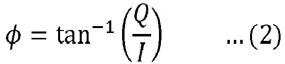
FIG. 6 is a schematic diagram of an exemplaryneural network model 300 that may be used in the embodiment ofFig. 5 for determining high-resolution denoised phase. Theneural network model 300 may include a convolutionalneural network 302. Theneural network 302 accepts aMR phase image 304 contaminated with corrupted phase information (i.e., a corrupted image) and returns apristine phase image 306, where thebackground phase 308 has been substantially denoised. Inputs and outputs to theneural network 302 may also be complex images, magnitude and phase image pairs, or real or imaginary image pairs. In one embodiment, theneural network 302 may trained with a loss function, which is a function measuring the inference error by theneural network 302. The loss function may be expressed as min(f1(input) - f2(output)), where f1 and f2 are functions of the input and the output to theneural network 302, respectively. In some embodiment, the loss function includes constraints based on prior knowledge of the phase information. For example, prior knowledge is that phase aliasing or phase wrapping may be caused by the computation method of phases. The phase calculated based on the equation of phase Φ(x, y) =
-
FIGs. 7A-7E provide a comparison of k-space data reconstruction using conventional homodyne method with the modified homodyne technique presented herein.FIG. 7A is aphantom image 402 corresponding to a fully sampled k-space.FIG. 7B is aphase image 404 of thephantom image 402.FIG. 7C is a zero filledphantom image 406 corresponding to a partial k-space data set.FIG. 7D is aphantom image 408 after phase correction corresponding to a conventional homodyne method as described inFig. 5 . Further,FIG. 7E is a phase correctedphantom image 410 according to the modified homodyne technique presented herein. It should be noted that all the images presented inFigs. 7A-7E are simulated phantom images. As can be seen fromFig. 7D , thephantom image 408 generated with the conventional homodyne method includesartifacts Fig. 7E ) generated with the proposed modified Homodyne reconstruction method which looks very similar to thephantom image 402 generated with fully sampled k-space. -
Figs. 8A-8B provide another comparison of k-space data reconstruction using conventional homodyne method with the modified homodyne technique presented herein.FIG. 8A is a simulatedabdominal image 502 after phase correction corresponding to a conventional homodyne method as described inFig. 5 . Further,FIG. 8B is a phase corrected simulatedabdominal image 504 according to the modified homodyne technique presented herein. As can be seen from, theartifacts Fig. 8A have been minimized to a great extent inimage 504 ofFig. 8B . In other words, the abdominal image generated using the conventional Homodyne is quite inferior to the abdominal image of the modified Homodyne technique with high resolution phase according to an embodiment of the present technique. -
Fig. 9 is aflow chart 800 depicting a method for producing an image of a subject with a magnetic resonance imaging (MRI) system. The method includes acquiring a first set of partial k-space data from the subject atstep 802. In one embodiment, the first set of k-space data is for less than all of k-space from the subject. In other words, the first set of partial k-space data include k-space data from a partial k-space that is truncated in at least one k-space dimension. Atstep 804, the method includes determining a phase correction factor. The phase correction factor may be determined from the first set of the partial k-space data. To determine the phase correction factor from the partial k-space data, first a crude image is reconstructed from the first set of the partial k-space data. In one embodiment, the crude image is reconstructed by zero-filling the first set of partial k-space data with zeros at locations corresponding to the skipped k-space locations to derive full k-space data, and then reconstructing the crude image based on the zero-filled k-space data. - Thereafter, one of a neural network model, a wavelet transform algorithm, a principal component analysis (PCA) algorithm or a total variance (TV) algorithm is used with the crude image to determine the phase correction factor. In one embodiment, the neural network model is trained with a pair of pristine images and corrupted images, wherein the corrupted images include corrupted phase information, the pristine images are the corrupted images with the corrupted phase information reduced. In another embodiment, the phase correction factor may be determined from an external image which is a pre-acquired high resolution image. Further, the crude image and the phase correction factor is multiplied to generate a phase corrected image at
step 806. Atstep 808, the method includes transforming the phase corrected image into a second set of partial k-space data. The transformation may be performed by applying a Fast Fourier Transform (FFT) on the phase corrected image. - At
step 810, the method includes reconstructing the image of the subject, from the second set of the partial k-space data and a weighting function. In one embodiment, the weighting function refers to spectral sampling density and may include a Hanning window function. First, the weighting function is multiplied with the second set of the partial k-space data to and then the real portion of the result is used as the desired image of the subject. - One advantage of the present technique is that it systematically minimizes common artifacts in MRI images such as in regions with rapid phase variations and can be broadly applied to improve the image quality of out-of-phase water-fat imaging, diffusion imaging, gradient echo imaging, etc. Further, since the technique uses a partial k-space data, efficiency of the MRI acquisition is improved.
- This written description uses examples to disclose the invention, including the best mode, and also to enable any person skilled in the art to practice the invention, including making and using any devices or systems and performing any incorporated methods. The patentable scope of the invention is defined by the claims, and may include other examples that occur to those skilled in the art. Such other examples are intended to be within the scope of the claims if they have structural elements that do not differ from the literal language of the claims, or if they include equivalent structural elements with insubstantial differences from the literal languages of the claims.
Claims (15)
- A method for producing an image of a subj ect with a magnetic resonance imaging (MRI) system, the method comprising:acquiring, using the MRI system, a first set of partial k-space data from the subj ect;generating a phase corrected image based on a phase correction factor and the first set of the partial k-space data;transforming the phase corrected image into a second set of partial k-space data;reconstructing, from the second set of the partial k-space data and a weighting function, the image of the subject.
- The method of claim 1, wherein the phase correction factor is determined from the first set of the partial k-space data or a pre-acquired high resolution image.
- The method of claim 1 comprising reconstructing a crude image from the first set of the partial k-space data.
- The method of claim 3, wherein crude image is reconstructed by zero-filling the first set of partial k-space data with zeros at locations corresponding to the skipped k-space locations to derive full k-space data, and then reconstructing the crude image based on the zero-filled k-space data.
- The method of claim 4, comprises using one of a neural network model, a wavelet transform algorithm, a principal component analysis (PCA) algorithm or a total variance (TV) algorithm with the crude image to determine the phase correction factor.
- The method of claim 5, wherein the neural network model is trained with a pair of pristine images and corrupted images, wherein the corrupted images include corrupted phase information, the pristine images are the corrupted images with the corrupted phase information reduced.
- The method of claim 5, wherein the neural network model is trained with a loss function including a constraint based on prior knowledge of phase information.
- The method of claim 1, wherein the first set of partial k-space data include k-space data from a partial k-space that is truncated in at least one k-space dimension.
- The method of claim 1, wherein generating the phase corrected image based on the phase correction factor and the first set of the partial k-space data comprises multiplying the crude image with the phase correction factor.
- The method of claim 1, wherein the image of the subject is reconstructed by determining a real portion of a multiplication result of the weighting function and the second set of the partial k-space data.
- The method of claim 1, wherein the weighting function represents a spectral sampling density.
- A magnetic resonance imaging (MRI) system, comprising.a magnet configured to generate a polarizing magnetic field about at least a portion of a subject arranged in the MRI system;a gradient coil assembly including a plurality of gradient coils configured to apply at least one gradient field to the polarizing magnetic field;a radio frequency (RF) system configured to apply an RF field to the subject and to receive magnetic resonance signals from the subject;a processing system programmed to:acquire a first set of partial k-space data from the subject;generate a phase corrected image based on a phase correction factor and the first set of the partial k-space data;transform the phase corrected image into a second set of partial k-space data;reconstruct, from the second set of the partial k-space data and a weighting function, the image of the subject.
- The MRI system of claim 12, wherein the processing system is programmed to determine the phase correction factor from the first set of the partial k-space data or a pre-acquired high resolution image.
- The MRI system of claim 12, wherein the processing system is programmed to reconstruct a crude image from the first set of the partial k-space data.
- A method of MR imaging comprising:acquiring a first set of k-space data for less than all of k-space from a subject;reconstructing the k-space data into a crude image;generating a phase corrected image based on a phase correction factor and the first set of k-space data;transforming the phase corrected image into a second set of k-space data;reconstructing, from the second set of the k-space data and a weighting function, the image of the subject.
Applications Claiming Priority (1)
| Application Number | Priority Date | Filing Date | Title |
|---|---|---|---|
| US17/172,644 US12201412B2 (en) | 2021-02-10 | 2021-02-10 | System and method for reconstruction using a high-resolution phase in magnetic resonance images |
Publications (2)
| Publication Number | Publication Date |
|---|---|
| EP4092439A1 true EP4092439A1 (en) | 2022-11-23 |
| EP4092439B1 EP4092439B1 (en) | 2024-12-11 |
Family
ID=80001467
Family Applications (1)
| Application Number | Title | Priority Date | Filing Date |
|---|---|---|---|
| EP22152878.9A Active EP4092439B1 (en) | 2021-02-10 | 2022-01-24 | System and method for reconstruction using a high-resolution phase in magnetic resonance images |
Country Status (3)
| Country | Link |
|---|---|
| US (1) | US12201412B2 (en) |
| EP (1) | EP4092439B1 (en) |
| CN (1) | CN114913255B (en) |
Families Citing this family (5)
| Publication number | Priority date | Publication date | Assignee | Title |
|---|---|---|---|---|
| US11763429B2 (en) * | 2021-05-19 | 2023-09-19 | GE Precision Healthcare LLC | Deep learning based medical system and method for image acquisition |
| EP4160244A1 (en) * | 2021-09-29 | 2023-04-05 | Siemens Healthcare GmbH | Partial fourier magnetic resonance imaging method with neural networks |
| CN115639510A (en) * | 2022-10-09 | 2023-01-24 | 深圳市联影高端医疗装备创新研究院 | Magnetic resonance imaging method, spectroscopic imaging method, apparatus, device, and storage medium |
| CN115754859A (en) * | 2022-10-31 | 2023-03-07 | 中科微影(浙江)医疗科技有限公司 | MRI reconstruction method based on K space sampling |
| CN119313770B (en) * | 2024-12-16 | 2025-03-14 | 浙江大学 | Image reconstruction method for correcting magnetic resonance imaging distortion and magnetic resonance imaging system |
Citations (1)
| Publication number | Priority date | Publication date | Assignee | Title |
|---|---|---|---|---|
| US20120074940A1 (en) * | 2010-09-28 | 2012-03-29 | Tokunori Kimura | Magnetic resonance imaging apparatus and magnetic resonance imaging method |
Family Cites Families (14)
| Publication number | Priority date | Publication date | Assignee | Title |
|---|---|---|---|---|
| US7277597B2 (en) * | 2003-06-17 | 2007-10-02 | The Board Of Trustees Of The Leland Stanford Junior University | Partial k-space reconstruction for radial k-space trajectories in magnetic resonance imaging |
| US7652474B2 (en) | 2007-05-02 | 2010-01-26 | Griswold Mark A | Conjugate symmetry in parallel imaging |
| CN104838279B (en) * | 2012-12-06 | 2018-03-30 | 皇家飞利浦有限公司 | Local artefacts with unconspicuous side effect reduce |
| US9329250B2 (en) * | 2013-03-14 | 2016-05-03 | Wisconsin Alumni Resesarch Foundation | System and method for combined chemical species separation and high resolution R2* mapping with magnetic resonance imaging |
| US10068328B2 (en) * | 2015-12-22 | 2018-09-04 | Siemens Healthcare Gmbh | Sparse iterative phase correction for MR partial fourier reconstruction |
| CN106597333B (en) * | 2016-12-30 | 2019-05-31 | 上海联影医疗科技有限公司 | A kind of magnetic resonance parallel imaging method and magnetic resonance imaging system |
| EP3447520A1 (en) * | 2017-08-22 | 2019-02-27 | Koninklijke Philips N.V. | Data-driven correction of phase depending artefacts in a magnetic resonance imaging system |
| US10901061B2 (en) * | 2018-06-01 | 2021-01-26 | The General Hospital Corporation | Accelerated diffusion-weighted magnetic resonance imaging with self-navigated, phase corrected tilted kernel reconstruction of phase encoded and point spread function encoded k-space |
| CN109239631B (en) | 2018-08-03 | 2021-02-23 | 上海东软医疗科技有限公司 | Magnetic resonance imaging method and device |
| US10635943B1 (en) | 2018-08-07 | 2020-04-28 | General Electric Company | Systems and methods for noise reduction in medical images with deep neural networks |
| US10915990B2 (en) | 2018-10-18 | 2021-02-09 | General Electric Company | Systems and methods for denoising medical images with deep learning network |
| CN109658471B (en) | 2018-12-20 | 2023-07-25 | 上海联影医疗科技股份有限公司 | Method and system for medical image reconstruction |
| EP3730964A1 (en) * | 2019-04-26 | 2020-10-28 | Siemens Healthcare GmbH | Computer implemented method and system for magnetic resonance imaging |
| DE102020209913A1 (en) * | 2020-08-05 | 2021-07-22 | Siemens Healthcare Gmbh | Computer-implemented method for correcting phase-based artifacts in magnetic resonance, correction system, computer program and electronically readable data carrier |
-
2021
- 2021-02-10 US US17/172,644 patent/US12201412B2/en active Active
-
2022
- 2022-01-24 EP EP22152878.9A patent/EP4092439B1/en active Active
- 2022-01-28 CN CN202210110223.8A patent/CN114913255B/en active Active
Patent Citations (1)
| Publication number | Priority date | Publication date | Assignee | Title |
|---|---|---|---|---|
| US20120074940A1 (en) * | 2010-09-28 | 2012-03-29 | Tokunori Kimura | Magnetic resonance imaging apparatus and magnetic resonance imaging method |
Non-Patent Citations (2)
| Title |
|---|
| JOSEPH SURESH PAUL ET AL: "A higher dimensional homodyne filter for phase sensitive partial Fourier reconstruction of magnetic resonance imaging", MAGNETIC RESONANCE IMAGING, vol. 33, no. 9, 25 June 2015 (2015-06-25), TARRYTOWN, NY, US, pages 1114 - 1125, XP055626475, ISSN: 0730-725X, DOI: 10.1016/j.mri.2015.06.005 * |
| PEIBEI CAO ET AL: "Partial Fourier MRI Reconstruction Using Convolutional Neural Networks", PROCEEDINGS OF THE INTERNATIONAL SOCIETY FOR MAGNETIC RESONANCE IN MEDICINE, 28TH ANNUAL MEETING AND EXHIBITION, 8-14 AUGUST 2020, vol. 28, 3627, 24 July 2020 (2020-07-24), XP040717542 * |
Also Published As
| Publication number | Publication date |
|---|---|
| US12201412B2 (en) | 2025-01-21 |
| US20220248972A1 (en) | 2022-08-11 |
| CN114913255A (en) | 2022-08-16 |
| EP4092439B1 (en) | 2024-12-11 |
| CN114913255B (en) | 2025-05-16 |
Similar Documents
| Publication | Publication Date | Title |
|---|---|---|
| CN111513716B (en) | Method and system for magnetic resonance image reconstruction using an extended sensitivity model and a deep neural network | |
| EP4092439B1 (en) | System and method for reconstruction using a high-resolution phase in magnetic resonance images | |
| US11143730B2 (en) | System and method for parallel magnetic resonance imaging | |
| US9778336B2 (en) | System and method for rapid, multi-shot segmented magnetic resonance imaging | |
| US9588207B2 (en) | System for reconstructing MRI images acquired in parallel | |
| US7592808B1 (en) | System and method for reducing MR scan time using partial fourier acquisition and compressed sensing | |
| US10520573B2 (en) | System and method for performing wave-encoded magnetic resonance imaging of an object | |
| US9360542B2 (en) | System and method for spectrally-resolved three-dimensional magnetic resonance imaging without frequency-encoding gradients | |
| US7372269B2 (en) | Magnetic resonance imaging method and apparatus | |
| US11002815B2 (en) | System and method for reducing artifacts in echo planar magnetic resonance imaging | |
| US8482279B2 (en) | System and method of parallel imaging for magnetic resonance imaging near metallic implants | |
| US8421459B2 (en) | System and method for reducing blurring artifacts in multi-spectral MR imaging near metal | |
| US10605881B2 (en) | Magnetic resonance imaging apparatus and image processing method | |
| CN110389310B (en) | Method and control device for generating magnetic resonance recordings | |
| US11393073B2 (en) | Magnetic resonance imaging apparatus and noise elimination method | |
| US11009577B2 (en) | System and method for Nyquist ghost correction in medical imaging | |
| US20150204957A1 (en) | System and method for fully phase-encoded magnetic resonance imaging using multiband radio frequency excitation | |
| CN114663537A (en) | Deep learning system and method for removing truncation artifacts in magnetic resonance images | |
| US12078696B2 (en) | Silent calibration for magnetic resonance imaging | |
| US12487307B2 (en) | Distortion-free diffusion and quantitative magnetic resonance imaging with blip up-down acquisition of spin- and gradient-echoes | |
| US20240385267A1 (en) | Single coil deep learning based magnetic resonance imaging system and method | |
| US12092715B2 (en) | Magnetic resonance imaging system and method | |
| US11519990B1 (en) | Magnetic resonance imaging system and method | |
| JP2008099717A (en) | Magnetic resonance imaging system | |
| CN120477741A (en) | Method and system for enhancing acceleration of MRI scans using adama excitation |
Legal Events
| Date | Code | Title | Description |
|---|---|---|---|
| PUAI | Public reference made under article 153(3) epc to a published international application that has entered the european phase |
Free format text: ORIGINAL CODE: 0009012 |
|
| STAA | Information on the status of an ep patent application or granted ep patent |
Free format text: STATUS: REQUEST FOR EXAMINATION WAS MADE |
|
| 17P | Request for examination filed |
Effective date: 20220124 |
|
| AK | Designated contracting states |
Kind code of ref document: A1 Designated state(s): AL AT BE BG CH CY CZ DE DK EE ES FI FR GB GR HR HU IE IS IT LI LT LU LV MC MK MT NL NO PL PT RO RS SE SI SK SM TR |
|
| P01 | Opt-out of the competence of the unified patent court (upc) registered |
Effective date: 20230528 |
|
| REG | Reference to a national code |
Ref country code: DE Ref legal event code: R079 Free format text: PREVIOUS MAIN CLASS: G01R0033561000 Ipc: G01R0033480000 Ref country code: DE Ref legal event code: R079 Ref document number: 602022008501 Country of ref document: DE Free format text: PREVIOUS MAIN CLASS: G01R0033561000 Ipc: G01R0033480000 |
|
| RIC1 | Information provided on ipc code assigned before grant |
Ipc: G01R 33/56 20060101ALI20240226BHEP Ipc: G01R 33/561 20060101ALI20240226BHEP Ipc: G01R 33/48 20060101AFI20240226BHEP |
|
| GRAP | Despatch of communication of intention to grant a patent |
Free format text: ORIGINAL CODE: EPIDOSNIGR1 |
|
| STAA | Information on the status of an ep patent application or granted ep patent |
Free format text: STATUS: GRANT OF PATENT IS INTENDED |
|
| INTG | Intention to grant announced |
Effective date: 20240409 |
|
| GRAJ | Information related to disapproval of communication of intention to grant by the applicant or resumption of examination proceedings by the epo deleted |
Free format text: ORIGINAL CODE: EPIDOSDIGR1 |
|
| STAA | Information on the status of an ep patent application or granted ep patent |
Free format text: STATUS: REQUEST FOR EXAMINATION WAS MADE |
|
| GRAP | Despatch of communication of intention to grant a patent |
Free format text: ORIGINAL CODE: EPIDOSNIGR1 |
|
| STAA | Information on the status of an ep patent application or granted ep patent |
Free format text: STATUS: GRANT OF PATENT IS INTENDED |
|
| INTC | Intention to grant announced (deleted) | ||
| INTG | Intention to grant announced |
Effective date: 20240802 |
|
| GRAS | Grant fee paid |
Free format text: ORIGINAL CODE: EPIDOSNIGR3 |
|
| GRAA | (expected) grant |
Free format text: ORIGINAL CODE: 0009210 |
|
| STAA | Information on the status of an ep patent application or granted ep patent |
Free format text: STATUS: THE PATENT HAS BEEN GRANTED |
|
| AK | Designated contracting states |
Kind code of ref document: B1 Designated state(s): AL AT BE BG CH CY CZ DE DK EE ES FI FR GB GR HR HU IE IS IT LI LT LU LV MC MK MT NL NO PL PT RO RS SE SI SK SM TR |
|
| REG | Reference to a national code |
Ref country code: GB Ref legal event code: FG4D |
|
| REG | Reference to a national code |
Ref country code: CH Ref legal event code: EP |
|
| REG | Reference to a national code |
Ref country code: DE Ref legal event code: R096 Ref document number: 602022008501 Country of ref document: DE |
|
| REG | Reference to a national code |
Ref country code: IE Ref legal event code: FG4D |
|
| REG | Reference to a national code |
Ref country code: LT Ref legal event code: MG9D |
|
| PG25 | Lapsed in a contracting state [announced via postgrant information from national office to epo] |
Ref country code: HR Free format text: LAPSE BECAUSE OF FAILURE TO SUBMIT A TRANSLATION OF THE DESCRIPTION OR TO PAY THE FEE WITHIN THE PRESCRIBED TIME-LIMIT Effective date: 20241211 |
|
| PG25 | Lapsed in a contracting state [announced via postgrant information from national office to epo] |
Ref country code: FI Free format text: LAPSE BECAUSE OF FAILURE TO SUBMIT A TRANSLATION OF THE DESCRIPTION OR TO PAY THE FEE WITHIN THE PRESCRIBED TIME-LIMIT Effective date: 20241211 |
|
| PG25 | Lapsed in a contracting state [announced via postgrant information from national office to epo] |
Ref country code: BG Free format text: LAPSE BECAUSE OF FAILURE TO SUBMIT A TRANSLATION OF THE DESCRIPTION OR TO PAY THE FEE WITHIN THE PRESCRIBED TIME-LIMIT Effective date: 20241211 |
|
| REG | Reference to a national code |
Ref country code: NL Ref legal event code: MP Effective date: 20241211 |
|
| PG25 | Lapsed in a contracting state [announced via postgrant information from national office to epo] |
Ref country code: ES Free format text: LAPSE BECAUSE OF FAILURE TO SUBMIT A TRANSLATION OF THE DESCRIPTION OR TO PAY THE FEE WITHIN THE PRESCRIBED TIME-LIMIT Effective date: 20241211 |
|
| PG25 | Lapsed in a contracting state [announced via postgrant information from national office to epo] |
Ref country code: NO Free format text: LAPSE BECAUSE OF FAILURE TO SUBMIT A TRANSLATION OF THE DESCRIPTION OR TO PAY THE FEE WITHIN THE PRESCRIBED TIME-LIMIT Effective date: 20250311 |
|
| PG25 | Lapsed in a contracting state [announced via postgrant information from national office to epo] |
Ref country code: GR Free format text: LAPSE BECAUSE OF FAILURE TO SUBMIT A TRANSLATION OF THE DESCRIPTION OR TO PAY THE FEE WITHIN THE PRESCRIBED TIME-LIMIT Effective date: 20250312 Ref country code: LV Free format text: LAPSE BECAUSE OF FAILURE TO SUBMIT A TRANSLATION OF THE DESCRIPTION OR TO PAY THE FEE WITHIN THE PRESCRIBED TIME-LIMIT Effective date: 20241211 |
|
| PG25 | Lapsed in a contracting state [announced via postgrant information from national office to epo] |
Ref country code: RS Free format text: LAPSE BECAUSE OF FAILURE TO SUBMIT A TRANSLATION OF THE DESCRIPTION OR TO PAY THE FEE WITHIN THE PRESCRIBED TIME-LIMIT Effective date: 20250311 |
|
| PG25 | Lapsed in a contracting state [announced via postgrant information from national office to epo] |
Ref country code: NL Free format text: LAPSE BECAUSE OF FAILURE TO SUBMIT A TRANSLATION OF THE DESCRIPTION OR TO PAY THE FEE WITHIN THE PRESCRIBED TIME-LIMIT Effective date: 20241211 |
|
| REG | Reference to a national code |
Ref country code: AT Ref legal event code: MK05 Ref document number: 1750793 Country of ref document: AT Kind code of ref document: T Effective date: 20241211 |
|
| PG25 | Lapsed in a contracting state [announced via postgrant information from national office to epo] |
Ref country code: SM Free format text: LAPSE BECAUSE OF FAILURE TO SUBMIT A TRANSLATION OF THE DESCRIPTION OR TO PAY THE FEE WITHIN THE PRESCRIBED TIME-LIMIT Effective date: 20241211 |
|
| PG25 | Lapsed in a contracting state [announced via postgrant information from national office to epo] |
Ref country code: PL Free format text: LAPSE BECAUSE OF FAILURE TO SUBMIT A TRANSLATION OF THE DESCRIPTION OR TO PAY THE FEE WITHIN THE PRESCRIBED TIME-LIMIT Effective date: 20241211 |
|
| PG25 | Lapsed in a contracting state [announced via postgrant information from national office to epo] |
Ref country code: IS Free format text: LAPSE BECAUSE OF FAILURE TO SUBMIT A TRANSLATION OF THE DESCRIPTION OR TO PAY THE FEE WITHIN THE PRESCRIBED TIME-LIMIT Effective date: 20250411 |
|
| PG25 | Lapsed in a contracting state [announced via postgrant information from national office to epo] |
Ref country code: PT Free format text: LAPSE BECAUSE OF FAILURE TO SUBMIT A TRANSLATION OF THE DESCRIPTION OR TO PAY THE FEE WITHIN THE PRESCRIBED TIME-LIMIT Effective date: 20250411 |
|
| PG25 | Lapsed in a contracting state [announced via postgrant information from national office to epo] |
Ref country code: EE Free format text: LAPSE BECAUSE OF FAILURE TO SUBMIT A TRANSLATION OF THE DESCRIPTION OR TO PAY THE FEE WITHIN THE PRESCRIBED TIME-LIMIT Effective date: 20241211 |
|
| PG25 | Lapsed in a contracting state [announced via postgrant information from national office to epo] |
Ref country code: AT Free format text: LAPSE BECAUSE OF FAILURE TO SUBMIT A TRANSLATION OF THE DESCRIPTION OR TO PAY THE FEE WITHIN THE PRESCRIBED TIME-LIMIT Effective date: 20241211 Ref country code: RO Free format text: LAPSE BECAUSE OF FAILURE TO SUBMIT A TRANSLATION OF THE DESCRIPTION OR TO PAY THE FEE WITHIN THE PRESCRIBED TIME-LIMIT Effective date: 20241211 |
|
| PG25 | Lapsed in a contracting state [announced via postgrant information from national office to epo] |
Ref country code: SK Free format text: LAPSE BECAUSE OF FAILURE TO SUBMIT A TRANSLATION OF THE DESCRIPTION OR TO PAY THE FEE WITHIN THE PRESCRIBED TIME-LIMIT Effective date: 20241211 |
|
| PG25 | Lapsed in a contracting state [announced via postgrant information from national office to epo] |
Ref country code: CZ Free format text: LAPSE BECAUSE OF FAILURE TO SUBMIT A TRANSLATION OF THE DESCRIPTION OR TO PAY THE FEE WITHIN THE PRESCRIBED TIME-LIMIT Effective date: 20241211 |
|
| PG25 | Lapsed in a contracting state [announced via postgrant information from national office to epo] |
Ref country code: IT Free format text: LAPSE BECAUSE OF FAILURE TO SUBMIT A TRANSLATION OF THE DESCRIPTION OR TO PAY THE FEE WITHIN THE PRESCRIBED TIME-LIMIT Effective date: 20241211 |
|
| REG | Reference to a national code |
Ref country code: CH Ref legal event code: PL |
|
| PG25 | Lapsed in a contracting state [announced via postgrant information from national office to epo] |
Ref country code: SE Free format text: LAPSE BECAUSE OF FAILURE TO SUBMIT A TRANSLATION OF THE DESCRIPTION OR TO PAY THE FEE WITHIN THE PRESCRIBED TIME-LIMIT Effective date: 20241211 |
|
| REG | Reference to a national code |
Ref country code: DE Ref legal event code: R097 Ref document number: 602022008501 Country of ref document: DE |
|
| PG25 | Lapsed in a contracting state [announced via postgrant information from national office to epo] |
Ref country code: LU Free format text: LAPSE BECAUSE OF NON-PAYMENT OF DUE FEES Effective date: 20250124 Ref country code: MC Free format text: LAPSE BECAUSE OF FAILURE TO SUBMIT A TRANSLATION OF THE DESCRIPTION OR TO PAY THE FEE WITHIN THE PRESCRIBED TIME-LIMIT Effective date: 20241211 |
|
| PG25 | Lapsed in a contracting state [announced via postgrant information from national office to epo] |
Ref country code: DK Free format text: LAPSE BECAUSE OF FAILURE TO SUBMIT A TRANSLATION OF THE DESCRIPTION OR TO PAY THE FEE WITHIN THE PRESCRIBED TIME-LIMIT Effective date: 20241211 |
|
| PG25 | Lapsed in a contracting state [announced via postgrant information from national office to epo] |
Ref country code: BE Free format text: LAPSE BECAUSE OF NON-PAYMENT OF DUE FEES Effective date: 20250131 |
|
| PLBE | No opposition filed within time limit |
Free format text: ORIGINAL CODE: 0009261 |
|
| STAA | Information on the status of an ep patent application or granted ep patent |
Free format text: STATUS: NO OPPOSITION FILED WITHIN TIME LIMIT |
|
| PG25 | Lapsed in a contracting state [announced via postgrant information from national office to epo] |
Ref country code: CH Free format text: LAPSE BECAUSE OF NON-PAYMENT OF DUE FEES Effective date: 20250131 |
|
| REG | Reference to a national code |
Ref country code: BE Ref legal event code: MM Effective date: 20250131 |
|
| 26N | No opposition filed |
Effective date: 20250912 |
|
| PGFP | Annual fee paid to national office [announced via postgrant information from national office to epo] |
Ref country code: GB Payment date: 20251219 Year of fee payment: 5 |
|
| PGFP | Annual fee paid to national office [announced via postgrant information from national office to epo] |
Ref country code: FR Payment date: 20251217 Year of fee payment: 5 |
|
| PG25 | Lapsed in a contracting state [announced via postgrant information from national office to epo] |
Ref country code: IE Free format text: LAPSE BECAUSE OF NON-PAYMENT OF DUE FEES Effective date: 20250124 |
|
| PGFP | Annual fee paid to national office [announced via postgrant information from national office to epo] |
Ref country code: DE Payment date: 20251217 Year of fee payment: 5 |