EP4092326A1 - Nozzle tip with shielded core air for dual combustion systems - Google Patents
Nozzle tip with shielded core air for dual combustion systems Download PDFInfo
- Publication number
- EP4092326A1 EP4092326A1 EP22173883.4A EP22173883A EP4092326A1 EP 4092326 A1 EP4092326 A1 EP 4092326A1 EP 22173883 A EP22173883 A EP 22173883A EP 4092326 A1 EP4092326 A1 EP 4092326A1
- Authority
- EP
- European Patent Office
- Prior art keywords
- fuel
- conduit
- air
- fuel conduit
- nozzle assembly
- Prior art date
- Legal status (The legal status is an assumption and is not a legal conclusion. Google has not performed a legal analysis and makes no representation as to the accuracy of the status listed.)
- Granted
Links
Images

Classifications
-
- F—MECHANICAL ENGINEERING; LIGHTING; HEATING; WEAPONS; BLASTING
- F23—COMBUSTION APPARATUS; COMBUSTION PROCESSES
- F23R—GENERATING COMBUSTION PRODUCTS OF HIGH PRESSURE OR HIGH VELOCITY, e.g. GAS-TURBINE COMBUSTION CHAMBERS
- F23R3/00—Continuous combustion chambers using liquid or gaseous fuel
- F23R3/28—Continuous combustion chambers using liquid or gaseous fuel characterised by the fuel supply
-
- F—MECHANICAL ENGINEERING; LIGHTING; HEATING; WEAPONS; BLASTING
- F23—COMBUSTION APPARATUS; COMBUSTION PROCESSES
- F23R—GENERATING COMBUSTION PRODUCTS OF HIGH PRESSURE OR HIGH VELOCITY, e.g. GAS-TURBINE COMBUSTION CHAMBERS
- F23R3/00—Continuous combustion chambers using liquid or gaseous fuel
- F23R3/28—Continuous combustion chambers using liquid or gaseous fuel characterised by the fuel supply
- F23R3/283—Attaching or cooling of fuel injecting means including supports for fuel injectors, stems, or lances
-
- F—MECHANICAL ENGINEERING; LIGHTING; HEATING; WEAPONS; BLASTING
- F02—COMBUSTION ENGINES; HOT-GAS OR COMBUSTION-PRODUCT ENGINE PLANTS
- F02C—GAS-TURBINE PLANTS; AIR INTAKES FOR JET-PROPULSION PLANTS; CONTROLLING FUEL SUPPLY IN AIR-BREATHING JET-PROPULSION PLANTS
- F02C7/00—Features, components parts, details or accessories, not provided for in, or of interest apart form groups F02C1/00 - F02C6/00; Air intakes for jet-propulsion plants
- F02C7/22—Fuel supply systems
-
- F—MECHANICAL ENGINEERING; LIGHTING; HEATING; WEAPONS; BLASTING
- F02—COMBUSTION ENGINES; HOT-GAS OR COMBUSTION-PRODUCT ENGINE PLANTS
- F02C—GAS-TURBINE PLANTS; AIR INTAKES FOR JET-PROPULSION PLANTS; CONTROLLING FUEL SUPPLY IN AIR-BREATHING JET-PROPULSION PLANTS
- F02C7/00—Features, components parts, details or accessories, not provided for in, or of interest apart form groups F02C1/00 - F02C6/00; Air intakes for jet-propulsion plants
- F02C7/22—Fuel supply systems
- F02C7/222—Fuel flow conduits, e.g. manifolds
-
- F—MECHANICAL ENGINEERING; LIGHTING; HEATING; WEAPONS; BLASTING
- F23—COMBUSTION APPARATUS; COMBUSTION PROCESSES
- F23R—GENERATING COMBUSTION PRODUCTS OF HIGH PRESSURE OR HIGH VELOCITY, e.g. GAS-TURBINE COMBUSTION CHAMBERS
- F23R3/00—Continuous combustion chambers using liquid or gaseous fuel
- F23R3/28—Continuous combustion chambers using liquid or gaseous fuel characterised by the fuel supply
- F23R3/34—Feeding into different combustion zones
- F23R3/346—Feeding into different combustion zones for staged combustion
-
- F—MECHANICAL ENGINEERING; LIGHTING; HEATING; WEAPONS; BLASTING
- F23—COMBUSTION APPARATUS; COMBUSTION PROCESSES
- F23R—GENERATING COMBUSTION PRODUCTS OF HIGH PRESSURE OR HIGH VELOCITY, e.g. GAS-TURBINE COMBUSTION CHAMBERS
- F23R3/00—Continuous combustion chambers using liquid or gaseous fuel
- F23R3/28—Continuous combustion chambers using liquid or gaseous fuel characterised by the fuel supply
- F23R3/36—Supply of different fuels
-
- F—MECHANICAL ENGINEERING; LIGHTING; HEATING; WEAPONS; BLASTING
- F05—INDEXING SCHEMES RELATING TO ENGINES OR PUMPS IN VARIOUS SUBCLASSES OF CLASSES F01-F04
- F05D—INDEXING SCHEME FOR ASPECTS RELATING TO NON-POSITIVE-DISPLACEMENT MACHINES OR ENGINES, GAS-TURBINES OR JET-PROPULSION PLANTS
- F05D2220/00—Application
- F05D2220/30—Application in turbines
- F05D2220/32—Application in turbines in gas turbines
- F05D2220/323—Application in turbines in gas turbines for aircraft propulsion, e.g. jet engines
-
- F—MECHANICAL ENGINEERING; LIGHTING; HEATING; WEAPONS; BLASTING
- F23—COMBUSTION APPARATUS; COMBUSTION PROCESSES
- F23R—GENERATING COMBUSTION PRODUCTS OF HIGH PRESSURE OR HIGH VELOCITY, e.g. GAS-TURBINE COMBUSTION CHAMBERS
- F23R2900/00—Special features of, or arrangements for continuous combustion chambers; Combustion processes therefor
- F23R2900/00004—Preventing formation of deposits on surfaces of gas turbine components, e.g. coke deposits
Definitions
- This disclosure relates generally to fuel injection for gas turbine engines, and more particularly to applications with dual fuel injection. There is always a need in the art for improvements fuel nozzles in the aerospace industry.
- a nozzle assembly comprises a first fuel conduit defined between a nozzle body and a fuel swirler and extending along a longitudinal axis from an inlet of the first fuel conduit to an outlet of the fuel nozzle assembly.
- a second fuel conduit is defined between the fuel swirler and a heat shield and extending along the fuel swirler along the longitudinal axis from an inlet of the second fuel conduit to the outlet of the fuel nozzle assembly.
- An air conduit extends through the heat shield along the longitudinal axis from an inlet of the air conduit to the outlet of the fuel nozzle assembly.
- first fuel conduit and the second fuel conduit are annular and the second fuel conduit is positioned radially inward from the first fuel conduit.
- the air conduit is cylindrical and positioned radially inward from the second fuel conduit.
- an inlet of the air conduit is upstream of both the first fuel inlet and the second fuel inlets.
- the heat shield is an inner heat shield and the fuel nozzle assembly further comprises an outer heat shield mounted to the nozzle body.
- the outer heat shield further includes an air cap radially outward of the outer heat shield forming an insulative air gap therebetween.
- the air cap further includes an outer air conduit defined therein.
- a feed arm mounted to the outer nozzle body. At least a portion of the first fuel conduit is contained within the feed arm, such that the first fuel conduit passes laterally through the nozzle body into an annular space between the nozzle body and fuel swirler. At least a portion of the second fuel conduit is contained within the feed arm, such that the second fuel conduit passes from the feed arm, through a lateral port through the outer nozzle body, and into an annular space between the fuel swirler and the inner heat shield.
- an upstream seal and a downstream seal seal between the feed arm and the nozzle body, and are positioned such that the portion of the first fuel conduit contained within the feed arm is positioned between the upstream seal and the downstream seal.
- an upstream portion of the inner heat shield is sealed to the fuel swirler to prevent backflow from the second fuel conduit into a compressor space upstream of the inner air conduit.
- an upstream end of the inner air conduit is larger in diameter than a downstream end of the of the inner air conduit, and the upstream end of the inner air conduit is shorter axial length than the downstream portion of the inner air conduit.
- the inner air conduit extends from a position upstream of the inlet of the second fuel conduit, to a position at the downstream end of the first fuel conduit.
- the second fuel conduit extends along a majority of the axial length of the first fuel conduit.
- the first fuel conduit is configured for issuing first fuel as a swirling, atomized spray into a combustor space
- the second fuel conduit includes a hydrogen gas fuel conduit.
- the first fuel conduit and the second fuel conduit are fluidly isolated within the nozzle body.
- the air conduit is devoid of any air swirlers.
- the method includes combusting a first fuel from a first fuel conduit in a fuel nozzle, staging off flow of the first fuel through the first fuel conduit, staging on flow of a second fuel through a second fuel conduit and combusting the second fuel from the second fuel conduit, during the combusting the second fuel from the second fuel conduit, cooling the first fuel conduit with flow of the second fuel through the second fuel conduit.
- the cooling of the first fuel conduit further includes maintaining a temperature of the first fuel conduit below a break down temperature above which the first fuel forms coke deposits.
- the method further includes preventing back flow from the second fuel conduit into a compressor space upstream of an air conduit, where the air conduit is defined within a heat shield radially inboard of the second fuel conduit.
- the method further includes thermally insulating the second fuel conduit from hot compressor air within the air conduit with the heat shield.
- FIG. 1 a partial view of an embodiment of a system in accordance with the disclosure is shown in Fig. 1 and is designated generally by reference character 100.
- the systems and methods described herein can be used to improve fuel mixing and combustion.
- an aircraft 1 can include an engine 10, where the engine can be a propulsive energy engine (e.g. creating thrust for the aircraft 1), or a non-propulsive energy engine, and a fuel system 100.
- a compressor 14 supplies pressurized air to a primary gas path 12 (e.g. as shown in Fig. 1 ) of the aircraft engine 10, the primary gas path 12 including fluidly in series a combustor and nozzle manifold for issuing fluid to the combustor.
- the nozzle manifold can include a nozzle assembly 100 defining a longitudinal nozzle axis A, and comprising an annular first fuel conduit 102 defined between an outer nozzle body 104 and a fuel swirler 106 configured to issue first fuel 108 as a swirling, atomized spray 110 into a combustor space 112.
- the first fuel conduit 102 can extend from an upstream first fuel conduit inlet 114 to an outlet 116.
- An annular second fuel conduit 118 is defined between the fuel swirler 106 and an inner heat shield 120 configured to issue second fuel 122 into the combustor space 112 to mix with the first fuel 108.
- the first fuel conduit 102 and the second fuel conduit 118 can be fluidly isolated from one another.
- the second fuel conduit 118 can extend from an upstream second fuel conduit inlet 124 to the outlet 116.
- the second fuel inlet 124 is upstream of the first fuel inlet 114, relative to axis A.
- the second fuel conduit 118 can be positioned radially inward from the first fuel conduit 102.
- the first fuel 108 and the second fuel 122 can include any suitable combination of fuels, such as a liquid fuel (e.g. kerosene and/or biofuel) and or a gaseous fuel (e.g. at least a portion of hydrogen gas, and/or natural gas, or pure hydrogen gas), or both the first and second fuels 108, 122 can be liquid fuels.
- a cylindrical air conduit 126 is defined within a heat shield 120, extending downstream from an upstream air inlet 128 to the outlet 116 and can be positioned radially inward from the second fuel conduit 118.
- the upstream air inlet 128 is upstream of both the first fuel inlet 114 and the second fuel inlet 124, relative to axis A.
- the air conduit 126 can be devoid of any air swirlers or any other mixing features disposed therein.
- an upstream end 130 of the air conduit 126 can be larger in diameter d1 than a downstream end 132 of the of the air conduit 126 (e.g. d2 ), and the upstream end 130 of the air conduit 126 can have a shorter axial length l1 than the downstream portion 132 of the air conduit 126 (e.g. l2 ).
- the second fuel conduit 118 can extend along a majority of the axial length l 3 of the first fuel conduit 102 (e.g. 14 ), for example at least half the axial length of the second fuel conduit 118, or at least 75% of the axial length of the second fuel conduit 102 ( l4 ). Extending the second fuel conduit 118 over a greater length of the nozzle body 104 ( l5 ) and providing a relatively narrow passage, the second fuel 122 within the second fuel conduit 118 will act to cool the surrounding nozzle components for a longer period of time and more efficiently, than having a shorter second fuel conduit, for example.
- the air conduit 126 can extend from a position 134 upstream of the second fuel conduit inlet 124, to a position 136 at the downstream end of the first fuel conduit 102, for example extending beyond both the first and second fuel conduits 102, 118, and along the entire axial length l5 of the nozzle body 104.
- the size, shape, and orientation of each of the air and/or fuel conduits relative to one another can be optimized to achieve specific benefits and/or nozzle performance as needed or desired, without departing from the scope of this disclosure.
- the nozzle 100 includes a second heat shield, e.g. an outer heat shield 138 mounted to the nozzle body 104.
- An air cap 140 is mounted to and radially outward of the outer heat shield 138 forming an insulative air gap 142 between the air cap 140 and the outer heat shield 138.
- the air cap 140 can include an outer air conduit (e.g. orifices 144) defined therein. Both the inner and outer air conduits 126, 144 deliver air that may or may not be compressed to the nozzle 100 to combine with the first and second fuels 108, 122.
- any suitable number of orifices can be used in the inner and outer air conduits 126, 144, and the size, shape and area of the air conduits 126, 144 can be optimized for the desired air to fuel ratio for ignition and operation, as appreciated by those having ordinary skill in the art.
- a feed arm 146 is mounted to the outer nozzle body 104 for issuing the first and second fuel 108, 122 to the nozzle body. At least a portion 148 of the first fuel conduit 102 is contained within the feed arm 146, such that the first fuel conduit 102 passes laterally through a lateral port 150 in the outer heat shield 138 into an annular space 151 between the outer nozzle body 104 and the fuel swirler 106. Similarly, at least a portion 152 of the second fuel conduit 118 is contained within the feed arm 146, such that the second fuel conduit 118 passes from the feed arm 146, through a lateral port 154 through the outer nozzle body 104 and fuel swirler 106, and into an annular space 156 between the fuel swirler 106 and the heat shield 120.
- the second fuel conduit 118 is injected from the feed arm 146 into the nozzle body 104 within the second fuel conduit 118, and not directly into the air conduit 126. Instead, an upstream portion 158 of the inner heat shield 120 is sealed to the fuel swirler 106 to keep the second fuel 122 fluidly isolated from the inner air conduit 126 altogether within the nozzle body 104, and to prevent backflow from the second fuel conduit 118 into a compressor space 160 upstream of the inner air conduit 126.
- the second fuel 122 should not mix with the high pressure, high velocity hot air (e.g. air in air conduit 126) either within the engine compressor space 160, or within the air conduit 126 to avoid combustion of the second fuel 122 anywhere outside of the combustor space 112.
- An upstream seal 162 and a downstream seal 164 are configured to seal between the feed arm 146 and the outer nozzle body 104. As shown, the seals 162, 164 can be positioned such that the portion 148 of the first fuel conduit 102 contained within the feed arm 146 is situated between the upstream seal 162 and the downstream seal 164. Any number of additional seals may be included as needed, and in any suitable position.
- the method includes combusting first fuel 108 from the first fuel conduit 102 in the fuel nozzle 100; staging off flow of the first fuel 108 through the first fuel conduit 102; staging on flow of second fuel 122 through the second fuel conduit 118 and combusting the second fuel 122 from the second fuel conduit 118; and during the combusting the second fuel 122, cooling the first fuel conduit 102 with flow of the second fuel 122 through the second fuel conduit 118.
- the method includes issuing air through any one of inner air conduit 126 and/or outer air conduit (orifices 144), without passing the air through any air swirlers or mixing features within the respective air conduits 126, 144.
- Cooling the first fuel 108 can further include maintaining a temperature of the first fuel conduit 102 below a break down temperature, above which the first fuel 108 forms coke deposits. Preventing coking in the nozzle 100 can improve nozzle performance and overall workable life of the nozzle 108.
- the method can further include preventing back flow of second fuel 122 from the second fuel conduit 118 into the compressor space 160 upstream of the inner air conduit 126.
- the method can further include thermally insulating the second fuel conduit 118 from hot air within the air conduit 118 with the heat shield 120.
Landscapes
- Engineering & Computer Science (AREA)
- Chemical & Material Sciences (AREA)
- Combustion & Propulsion (AREA)
- Mechanical Engineering (AREA)
- General Engineering & Computer Science (AREA)
- Fuel-Injection Apparatus (AREA)
Abstract
Description
- This disclosure relates generally to fuel injection for gas turbine engines, and more particularly to applications with dual fuel injection. There is always a need in the art for improvements fuel nozzles in the aerospace industry.
- In one aspect of the present disclosure, there is provided a nozzle assembly comprises a first fuel conduit defined between a nozzle body and a fuel swirler and extending along a longitudinal axis from an inlet of the first fuel conduit to an outlet of the fuel nozzle assembly. A second fuel conduit is defined between the fuel swirler and a heat shield and extending along the fuel swirler along the longitudinal axis from an inlet of the second fuel conduit to the outlet of the fuel nozzle assembly. An air conduit extends through the heat shield along the longitudinal axis from an inlet of the air conduit to the outlet of the fuel nozzle assembly.
- In embodiments, the first fuel conduit and the second fuel conduit are annular and the second fuel conduit is positioned radially inward from the first fuel conduit. The air conduit is cylindrical and positioned radially inward from the second fuel conduit. In certain embodiments, an inlet of the air conduit is upstream of both the first fuel inlet and the second fuel inlets.
- In certain embodiments, the heat shield is an inner heat shield and the fuel nozzle assembly further comprises an outer heat shield mounted to the nozzle body. In certain such embodiments, the outer heat shield further includes an air cap radially outward of the outer heat shield forming an insulative air gap therebetween. In embodiments, the air cap further includes an outer air conduit defined therein.
- In embodiments, a feed arm mounted to the outer nozzle body. At least a portion of the first fuel conduit is contained within the feed arm, such that the first fuel conduit passes laterally through the nozzle body into an annular space between the nozzle body and fuel swirler. At least a portion of the second fuel conduit is contained within the feed arm, such that the second fuel conduit passes from the feed arm, through a lateral port through the outer nozzle body, and into an annular space between the fuel swirler and the inner heat shield.
- In embodiments, an upstream seal and a downstream seal seal between the feed arm and the nozzle body, and are positioned such that the portion of the first fuel conduit contained within the feed arm is positioned between the upstream seal and the downstream seal. In embodiments, an upstream portion of the inner heat shield is sealed to the fuel swirler to prevent backflow from the second fuel conduit into a compressor space upstream of the inner air conduit.
- In certain embodiments, an upstream end of the inner air conduit is larger in diameter than a downstream end of the of the inner air conduit, and the upstream end of the inner air conduit is shorter axial length than the downstream portion of the inner air conduit. In certain embodiments, the inner air conduit extends from a position upstream of the inlet of the second fuel conduit, to a position at the downstream end of the first fuel conduit. In certain such embodiments, the second fuel conduit extends along a majority of the axial length of the first fuel conduit.
- The first fuel conduit is configured for issuing first fuel as a swirling, atomized spray into a combustor space, and the second fuel conduit includes a hydrogen gas fuel conduit. The first fuel conduit and the second fuel conduit are fluidly isolated within the nozzle body. In embodiments, the air conduit is devoid of any air swirlers.
- In another aspect of the present disclosure, there is provided a method of thermal management for fuel injection. In certain embodiments, the method includes combusting a first fuel from a first fuel conduit in a fuel nozzle, staging off flow of the first fuel through the first fuel conduit, staging on flow of a second fuel through a second fuel conduit and combusting the second fuel from the second fuel conduit, during the combusting the second fuel from the second fuel conduit, cooling the first fuel conduit with flow of the second fuel through the second fuel conduit.
- In embodiments, the cooling of the first fuel conduit further includes maintaining a temperature of the first fuel conduit below a break down temperature above which the first fuel forms coke deposits. In certain embodiments, the method further includes preventing back flow from the second fuel conduit into a compressor space upstream of an air conduit, where the air conduit is defined within a heat shield radially inboard of the second fuel conduit. In certain embodiments, the method further includes thermally insulating the second fuel conduit from hot compressor air within the air conduit with the heat shield.
- These and other features of the systems and methods of the subject disclosure will become more readily apparent to those skilled in the art from the following detailed description taken in conjunction with the drawings.
- So that those skilled in the art to which the subject disclosure appertains will readily understand how to make and use the devices and methods of the subject disclosure without undue experimentation, embodiments thereof will be described in detail herein below with reference to certain figures, wherein:
-
Fig. 1 is a schematic view of an embodiment of an aircraft in accordance with this disclosure; and -
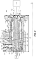
Fig. 2 is a schematic perspective view of an embodiment of a nozzle assembly constructed in accordance with the present disclosure, showing an arrangement of air and fuel conduits. - Reference will now be made to the drawings wherein like reference numerals identify similar structural features or aspects of the subject disclosure. For purposes of explanation and illustration, and not limitation, a partial view of an embodiment of a system in accordance with the disclosure is shown in
Fig. 1 and is designated generally byreference character 100. The systems and methods described herein can be used to improve fuel mixing and combustion. - In certain embodiments, referring to
Fig. 1 , anaircraft 1 can include anengine 10, where the engine can be a propulsive energy engine (e.g. creating thrust for the aircraft 1), or a non-propulsive energy engine, and afuel system 100. Acompressor 14 supplies pressurized air to a primary gas path 12 (e.g. as shown inFig. 1 ) of theaircraft engine 10, theprimary gas path 12 including fluidly in series a combustor and nozzle manifold for issuing fluid to the combustor. - With reference to
Fig. 2 , the nozzle manifold can include anozzle assembly 100 defining a longitudinal nozzle axis A, and comprising an annularfirst fuel conduit 102 defined between an outer nozzle body 104 and afuel swirler 106 configured to issuefirst fuel 108 as a swirling, atomizedspray 110 into acombustor space 112. Thefirst fuel conduit 102 can extend from an upstream firstfuel conduit inlet 114 to anoutlet 116. An annularsecond fuel conduit 118 is defined between thefuel swirler 106 and aninner heat shield 120 configured to issuesecond fuel 122 into thecombustor space 112 to mix with thefirst fuel 108. Within the nozzle body 104, thefirst fuel conduit 102 and thesecond fuel conduit 118 can be fluidly isolated from one another. - The
second fuel conduit 118 can extend from an upstream secondfuel conduit inlet 124 to theoutlet 116. In embodiments, thesecond fuel inlet 124 is upstream of thefirst fuel inlet 114, relative to axis A. As shown, thesecond fuel conduit 118 can be positioned radially inward from thefirst fuel conduit 102. In embodiments, thefirst fuel 108 and thesecond fuel 122 can include any suitable combination of fuels, such as a liquid fuel (e.g. kerosene and/or biofuel) and or a gaseous fuel (e.g. at least a portion of hydrogen gas, and/or natural gas, or pure hydrogen gas), or both the first andsecond fuels - A
cylindrical air conduit 126 is defined within aheat shield 120, extending downstream from anupstream air inlet 128 to theoutlet 116 and can be positioned radially inward from thesecond fuel conduit 118. Theupstream air inlet 128 is upstream of both thefirst fuel inlet 114 and thesecond fuel inlet 124, relative to axis A. In certain embodiments, theair conduit 126 can be devoid of any air swirlers or any other mixing features disposed therein. As shown, anupstream end 130 of theair conduit 126 can be larger in diameter d1 than adownstream end 132 of the of the air conduit 126 (e.g. d2), and theupstream end 130 of theair conduit 126 can have a shorter axial length l1 than thedownstream portion 132 of the air conduit 126 (e.g. l2). - In certain embodiments, the
second fuel conduit 118 can extend along a majority of the axial length l3 of the first fuel conduit 102 (e.g. 14), for example at least half the axial length of thesecond fuel conduit 118, or at least 75% of the axial length of the second fuel conduit 102 (l4). Extending thesecond fuel conduit 118 over a greater length of the nozzle body 104 (l5) and providing a relatively narrow passage, thesecond fuel 122 within thesecond fuel conduit 118 will act to cool the surrounding nozzle components for a longer period of time and more efficiently, than having a shorter second fuel conduit, for example. Theair conduit 126 can extend from aposition 134 upstream of the secondfuel conduit inlet 124, to aposition 136 at the downstream end of thefirst fuel conduit 102, for example extending beyond both the first andsecond fuel conduits - The
nozzle 100 includes a second heat shield, e.g. anouter heat shield 138 mounted to the nozzle body 104. Anair cap 140 is mounted to and radially outward of theouter heat shield 138 forming aninsulative air gap 142 between theair cap 140 and theouter heat shield 138. Theair cap 140 can include an outer air conduit (e.g. orifices 144) defined therein. Both the inner andouter air conduits nozzle 100 to combine with the first andsecond fuels outer air conduits air conduits - A
feed arm 146 is mounted to the outer nozzle body 104 for issuing the first andsecond fuel portion 148 of thefirst fuel conduit 102 is contained within thefeed arm 146, such that thefirst fuel conduit 102 passes laterally through alateral port 150 in theouter heat shield 138 into anannular space 151 between the outer nozzle body 104 and thefuel swirler 106. Similarly, at least aportion 152 of thesecond fuel conduit 118 is contained within thefeed arm 146, such that thesecond fuel conduit 118 passes from thefeed arm 146, through alateral port 154 through the outer nozzle body 104 andfuel swirler 106, and into anannular space 156 between thefuel swirler 106 and theheat shield 120. - As shown, the
second fuel conduit 118 is injected from thefeed arm 146 into the nozzle body 104 within thesecond fuel conduit 118, and not directly into theair conduit 126. Instead, anupstream portion 158 of theinner heat shield 120 is sealed to thefuel swirler 106 to keep thesecond fuel 122 fluidly isolated from theinner air conduit 126 altogether within the nozzle body 104, and to prevent backflow from thesecond fuel conduit 118 into acompressor space 160 upstream of theinner air conduit 126. Thesecond fuel 122 should not mix with the high pressure, high velocity hot air (e.g. air in air conduit 126) either within theengine compressor space 160, or within theair conduit 126 to avoid combustion of thesecond fuel 122 anywhere outside of thecombustor space 112. - An
upstream seal 162 and adownstream seal 164 are configured to seal between thefeed arm 146 and the outer nozzle body 104. As shown, theseals portion 148 of thefirst fuel conduit 102 contained within thefeed arm 146 is situated between theupstream seal 162 and thedownstream seal 164. Any number of additional seals may be included as needed, and in any suitable position. - In another aspect of the present disclosure, there is provided a method of thermal management for fuel injection, for example in
nozzle 100. In certain embodiments, the method includes combustingfirst fuel 108 from thefirst fuel conduit 102 in thefuel nozzle 100; staging off flow of thefirst fuel 108 through thefirst fuel conduit 102; staging on flow ofsecond fuel 122 through thesecond fuel conduit 118 and combusting thesecond fuel 122 from thesecond fuel conduit 118; and during the combusting thesecond fuel 122, cooling thefirst fuel conduit 102 with flow of thesecond fuel 122 through thesecond fuel conduit 118. The method includes issuing air through any one ofinner air conduit 126 and/or outer air conduit (orifices 144), without passing the air through any air swirlers or mixing features within therespective air conduits - Cooling the
first fuel 108 can further include maintaining a temperature of thefirst fuel conduit 102 below a break down temperature, above which thefirst fuel 108 forms coke deposits. Preventing coking in thenozzle 100 can improve nozzle performance and overall workable life of thenozzle 108. The method can further include preventing back flow ofsecond fuel 122 from thesecond fuel conduit 118 into thecompressor space 160 upstream of theinner air conduit 126. The method can further include thermally insulating thesecond fuel conduit 118 from hot air within theair conduit 118 with theheat shield 120. - The methods and systems of the present disclosure, as described above and shown in the drawings, provide for additional safety features in dual fuel nozzles using second fuel sources, by preventing unwanted back flow into the compressor, as well as limiting the possibility self-ignition of the second fuel by sealing against contact between the second fuel and the high velocity hot compressor air. While the apparatus and methods of the subject disclosure have been shown and described, those skilled in the art will readily appreciate that changes and/or modifications may be made thereto without departing from the scope of the subject disclosure.
Claims (15)
- A fuel nozzle assembly (100) for an aircraft engine (10), comprising:a first fuel conduit (102) defined between a nozzle body (104) and a fuel swirler (106) and extending along a longitudinal axis (A) from an inlet (114) of the first fuel conduit (102) to an outlet (116) of the fuel nozzle assembly (100);a second fuel conduit (118) defined between the fuel swirler (106) and a heat shield (120) and extending along the fuel swirler (106) along the longitudinal axis (A) from an inlet (124) of the second fuel conduit (118) to the outlet (116) of the fuel nozzle assembly (100); anda first air conduit (126) extending through the heat shield (120) along the longitudinal axis (A) from an inlet (128) of the first air conduit (126) to the outlet (116) of the fuel nozzle assembly (100).
- The fuel nozzle assembly (100) as recited in claim 1, wherein the first fuel conduit and the second fuel conduit (102, 118) are annular, wherein the second fuel conduit (118) is positioned radially inward from the first fuel conduit (102), and/or the first air conduit (126) is cylindrical and positioned radially inward from the second fuel conduit (118).
- The fuel nozzle assembly (100) as recited in claim 1 or 2, wherein the second fuel conduit inlet (124) is upstream of the first fuel conduit inlet (114), relative to the longitudinal axis (A).
- The fuel nozzle assembly (100) as recited in claim 1, 2 or 3, wherein the heat shield (120) is an inner heat shield (120) and the fuel nozzle assembly (100) further comprises an outer heat shield (138) mounted to the nozzle body (104).
- The fuel nozzle assembly (100) as recited in claim 4, wherein the outer heat shield (138) further includes an air cap (140) mounted to and radially outward of the outer heat shield (138) forming an insulative air gap (142) therebetween, wherein the air cap (140) further includes an outer second air conduit (144) defined therein.
- The fuel nozzle assembly (100) as recited in any preceding claim, wherein the inlet (128) of the first air conduit (126) is upstream of both the first fuel conduit inlet (114) and the second fuel conduit inlet (124), relative to the longitudinal axis (A).
- The fuel nozzle assembly (100) as recited in any preceding claim, further comprising a feed arm (146) mounted to the nozzle body (104).
- The fuel nozzle assembly (100) as recited in claim 7, wherein at least a portion (148) of the first fuel conduit (102) is contained within the feed arm (146), wherein the first fuel conduit (102) passes laterally through the nozzle body (104) into an annular space (151) between the nozzle body (104) and the fuel swirler (106), and wherein at least a portion (152) of the second fuel conduit (118) is contained within the feed arm (146), wherein the second fuel conduit (118) passes from the feed arm (146), through a lateral port (154) through the nozzle body (104), and into an annular space (156) between the fuel swirler (106) and the inner heat shield (120).
- The fuel nozzle assembly (100) as recited in claim 7 or 8, further comprising an upstream seal (162) and a downstream seal (164) configured to seal between the feed arm (146) and the nozzle body (104), wherein the portion (148) of the first fuel conduit (102) contained within the feed arm (146) is positioned between the upstream seal (162) and the downstream seal (164).
- The fuel nozzle assembly (100) as recited in any preceding claim, wherein an upstream portion (158) of the heat shield (120) is sealed to the fuel swirler (106) to prevent backflow from the second fuel conduit (118) into a compressor space (160) upstream of the first air conduit (126), relative to the longitudinal axis (A), and/or wherein an upstream end (130) of the first air conduit (126) is larger in diameter (d1) than a downstream end (132) of the of the first air conduit (126) and wherein the upstream end (130) of the first air conduit (126) is shorter in axial length (11) than the downstream portion (132) of the first air conduit (126).
- The fuel nozzle assembly (100) as recited in any preceding claim, wherein the first air conduit (126) extends from a position (134) upstream of the inlet (124) of the second fuel conduit (118), to a position (136) at the downstream end (132) of the first fuel conduit (102), relative to the longitudinal axis (A), and wherein the second fuel conduit (118) extends along a majority of the axial length (13) of the first fuel conduit (102), and/or wherein the first air conduit (126) is devoid of any air swirlers.
- The fuel nozzle assembly (100) as recited in any preceding claim, wherein, the first fuel conduit (102) issues a first fuel (108) as a swirling, atomized spray (110) into a combustor space (112), and/or wherein the first fuel conduit (102) and the second fuel conduit (118) are fluidly isolated within the nozzle body (104).
- A method of thermal management for fuel injection in an aircraft engine (10), comprising:combusting a first fuel (108) from a first fuel conduit (102) in a fuel nozzle (100);staging off flow of the first fuel (108) through the first fuel conduit (102);staging on flow of a second fuel (122) through a second fuel conduit (118) and combusting the second fuel (122) from the second fuel conduit (118); andduring the combusting the second fuel (122) from the second fuel conduit (118), cooling the first fuel conduit (102) with flow of the second fuel (122) through the second fuel conduit (118).
- The method as recited in claim 13, wherein the cooling of the first fuel conduit (102) further includes maintaining a temperature of the first fuel conduit (102) below a break down temperature above which the first fuel (108) forms coke deposits.
- The method as recited in claim 13 or 14, further comprising preventing back flow from the second fuel conduit (118) into a compressor space (160) upstream of an air conduit (126), wherein the air conduit (126) is defined within a heat shield (120) radially inboard of the second fuel conduit (118), and optionally further comprising thermally insulating the second fuel conduit (118) from hot compressor air within the air conduit (126) with the heat shield (120).
Applications Claiming Priority (1)
| Application Number | Priority Date | Filing Date | Title |
|---|---|---|---|
| US17/322,812 US12228284B2 (en) | 2021-05-17 | 2021-05-17 | Nozzle tip with shielded core for a dual combustion systems |
Publications (2)
| Publication Number | Publication Date |
|---|---|
| EP4092326A1 true EP4092326A1 (en) | 2022-11-23 |
| EP4092326B1 EP4092326B1 (en) | 2026-04-15 |
Family
ID=81748510
Family Applications (1)
| Application Number | Title | Priority Date | Filing Date |
|---|---|---|---|
| EP22173883.4A Active EP4092326B1 (en) | 2021-05-17 | 2022-05-17 | Fuel nozzle assembly for dual fuel combustion systems |
Country Status (3)
| Country | Link |
|---|---|
| US (1) | US12228284B2 (en) |
| EP (1) | EP4092326B1 (en) |
| CA (1) | CA3160870A1 (en) |
Families Citing this family (2)
| Publication number | Priority date | Publication date | Assignee | Title |
|---|---|---|---|---|
| US12571539B2 (en) * | 2023-12-08 | 2026-03-10 | General Electric Company | Turbine engine having a combustion section with a fuel nozzle |
| US20250251133A1 (en) * | 2024-02-02 | 2025-08-07 | General Electric Company | Turbine engine having a combustion section with a fuel supply assembly |
Citations (6)
| Publication number | Priority date | Publication date | Assignee | Title |
|---|---|---|---|---|
| US20140291418A1 (en) * | 2013-03-26 | 2014-10-02 | Parker-Hannifin Corporation | Multi-circuit airblast fuel nozzle |
| US20160116168A1 (en) * | 2014-10-27 | 2016-04-28 | Solar Turbines Incorporated | Robust insulated fuel injector for a gas turbine engine |
| US20160209037A1 (en) * | 2013-08-30 | 2016-07-21 | United Technologies Corporation | Dual Fuel Nozzle With Liquid Filming Atomization for a Gas Turbine Engine |
| US20160252252A1 (en) * | 2015-02-27 | 2016-09-01 | United Technologies Corporation | Line replaceable fuel nozzle apparatus, system and method |
| US20200003421A1 (en) * | 2017-03-13 | 2020-01-02 | Siemens Aktiengesellschaft | Fuel injector nozzle for combustion turbine engines including thermal stress-relief vanes |
| EP3628925A1 (en) * | 2018-09-28 | 2020-04-01 | Rolls-Royce plc | Fuel spray nozzle |
Family Cites Families (18)
| Publication number | Priority date | Publication date | Assignee | Title |
|---|---|---|---|---|
| US1854127A (en) | 1926-02-12 | 1932-04-12 | Oilgear Co | Hydraulic transmission |
| CA1178452A (en) | 1981-07-23 | 1984-11-27 | Robie L. Faulkner | Gas turbine engines |
| US4600151A (en) * | 1982-11-23 | 1986-07-15 | Ex-Cell-O Corporation | Fuel injector assembly with water or auxiliary fuel capability |
| US6622488B2 (en) | 2001-03-21 | 2003-09-23 | Parker-Hannifin Corporation | Pure airblast nozzle |
| EP1811229B1 (en) * | 2006-01-20 | 2021-04-28 | Parker-Hannifin Corporation | Fuel injector nozzles for gas turbine engines |
| US8196845B2 (en) | 2007-09-17 | 2012-06-12 | Delavan Inc | Flexure seal for fuel injection nozzle |
| US20090111063A1 (en) | 2007-10-29 | 2009-04-30 | General Electric Company | Lean premixed, radial inflow, multi-annular staged nozzle, can-annular, dual-fuel combustor |
| US20090255258A1 (en) | 2008-04-11 | 2009-10-15 | Delavan Inc | Pre-filming air-blast fuel injector having a reduced hydraulic spray angle |
| US8061142B2 (en) | 2008-04-11 | 2011-11-22 | General Electric Company | Mixer for a combustor |
| US8096135B2 (en) | 2008-05-06 | 2012-01-17 | Dela Van Inc | Pure air blast fuel injector |
| US20120180486A1 (en) | 2011-01-18 | 2012-07-19 | General Electric Company | Gas turbine fuel system for low dynamics |
| US9488371B2 (en) * | 2011-08-10 | 2016-11-08 | General Electric Company | System for gasification fuel injection |
| US20150337730A1 (en) * | 2012-12-28 | 2015-11-26 | General Electric Company | Turbine engine assemblies |
| RU2618801C2 (en) | 2013-01-10 | 2017-05-11 | Дженерал Электрик Компани | Fuel nozzle, end fuel nozzle unit, and gas turbine |
| US9562692B2 (en) | 2013-02-06 | 2017-02-07 | Siemens Aktiengesellschaft | Nozzle with multi-tube fuel passageway for gas turbine engines |
| US9618209B2 (en) | 2014-03-06 | 2017-04-11 | Solar Turbines Incorporated | Gas turbine engine fuel injector with an inner heat shield |
| WO2020180294A1 (en) | 2019-03-04 | 2020-09-10 | Siemens Energy, Inc. | Fuel injection nozzle including a heat shield |
| CN112254172B (en) | 2020-10-20 | 2022-06-10 | 中国航发沈阳发动机研究所 | Double-oil-way nozzle with heat insulation structure |
-
2021
- 2021-05-17 US US17/322,812 patent/US12228284B2/en active Active
-
2022
- 2022-05-13 CA CA3160870A patent/CA3160870A1/en active Pending
- 2022-05-17 EP EP22173883.4A patent/EP4092326B1/en active Active
Patent Citations (6)
| Publication number | Priority date | Publication date | Assignee | Title |
|---|---|---|---|---|
| US20140291418A1 (en) * | 2013-03-26 | 2014-10-02 | Parker-Hannifin Corporation | Multi-circuit airblast fuel nozzle |
| US20160209037A1 (en) * | 2013-08-30 | 2016-07-21 | United Technologies Corporation | Dual Fuel Nozzle With Liquid Filming Atomization for a Gas Turbine Engine |
| US20160116168A1 (en) * | 2014-10-27 | 2016-04-28 | Solar Turbines Incorporated | Robust insulated fuel injector for a gas turbine engine |
| US20160252252A1 (en) * | 2015-02-27 | 2016-09-01 | United Technologies Corporation | Line replaceable fuel nozzle apparatus, system and method |
| US20200003421A1 (en) * | 2017-03-13 | 2020-01-02 | Siemens Aktiengesellschaft | Fuel injector nozzle for combustion turbine engines including thermal stress-relief vanes |
| EP3628925A1 (en) * | 2018-09-28 | 2020-04-01 | Rolls-Royce plc | Fuel spray nozzle |
Also Published As
| Publication number | Publication date |
|---|---|
| US12228284B2 (en) | 2025-02-18 |
| EP4092326B1 (en) | 2026-04-15 |
| US20220364509A1 (en) | 2022-11-17 |
| CA3160870A1 (en) | 2022-11-17 |
Similar Documents
| Publication | Publication Date | Title |
|---|---|---|
| EP3168536B1 (en) | Gas turbine combustor | |
| EP3171088B1 (en) | Bundled tube fuel nozzle assembly with liquid fuel capability | |
| US8393155B2 (en) | Gas turbine fuel injector with insulating air shroud | |
| JP5762424B2 (en) | Multi-point fuel injector for turbine engine combustion chamber | |
| EP3260780B1 (en) | Gas turbine with a combustor having a fuel injector with heat pipe cooling | |
| EP3341656B1 (en) | Fuel nozzle assembly for a gas turbine | |
| US9650961B2 (en) | Gas turbine combustor including burner having plural gaseous fuel manifolds | |
| US9003804B2 (en) | Multipoint injectors with auxiliary stage | |
| US9021781B2 (en) | Fuel injector having an ignitor for igniting a combustor of a gas turbine | |
| EP4092326B1 (en) | Fuel nozzle assembly for dual fuel combustion systems | |
| CN113864818B (en) | Combustor air flow path | |
| CN109140506B (en) | Nozzle assembly for dual fuel nozzle | |
| US20130122437A1 (en) | Combustor and method for supplying fuel to a combustor | |
| US20140090381A1 (en) | Injection device for a combustion chamber of a turbine engine | |
| US10612775B2 (en) | Dual-fuel fuel nozzle with air shield | |
| CN109140505B (en) | Dual fuel nozzle and combustor | |
| US10955141B2 (en) | Dual-fuel fuel nozzle with gas and liquid fuel capability | |
| CN114483321B (en) | Integrated combustion nozzle with integral head | |
| EP4015908B1 (en) | Gas turbine engine combustor with axially oriented internally mounted continuous ignition device with reverse flow axial orientation | |
| EP3415818B1 (en) | Fuel supply assembly |
Legal Events
| Date | Code | Title | Description |
|---|---|---|---|
| PUAI | Public reference made under article 153(3) epc to a published international application that has entered the european phase |
Free format text: ORIGINAL CODE: 0009012 |
|
| STAA | Information on the status of an ep patent application or granted ep patent |
Free format text: STATUS: THE APPLICATION HAS BEEN PUBLISHED |
|
| AK | Designated contracting states |
Kind code of ref document: A1 Designated state(s): AL AT BE BG CH CY CZ DE DK EE ES FI FR GB GR HR HU IE IS IT LI LT LU LV MC MK MT NL NO PL PT RO RS SE SI SK SM TR |
|
| STAA | Information on the status of an ep patent application or granted ep patent |
Free format text: STATUS: REQUEST FOR EXAMINATION WAS MADE |
|
| 17P | Request for examination filed |
Effective date: 20230523 |
|
| RBV | Designated contracting states (corrected) |
Designated state(s): AL AT BE BG CH CY CZ DE DK EE ES FI FR GB GR HR HU IE IS IT LI LT LU LV MC MK MT NL NO PL PT RO RS SE SI SK SM TR |
|
| STAA | Information on the status of an ep patent application or granted ep patent |
Free format text: STATUS: EXAMINATION IS IN PROGRESS |
|
| 17Q | First examination report despatched |
Effective date: 20231204 |
|
| GRAP | Despatch of communication of intention to grant a patent |
Free format text: ORIGINAL CODE: EPIDOSNIGR1 |
|
| STAA | Information on the status of an ep patent application or granted ep patent |
Free format text: STATUS: GRANT OF PATENT IS INTENDED |
|
| INTG | Intention to grant announced |
Effective date: 20251106 |
|
| GRAS | Grant fee paid |
Free format text: ORIGINAL CODE: EPIDOSNIGR3 |
|
| GRAA | (expected) grant |
Free format text: ORIGINAL CODE: 0009210 |
|
| STAA | Information on the status of an ep patent application or granted ep patent |
Free format text: STATUS: THE PATENT HAS BEEN GRANTED |
|
| AK | Designated contracting states |
Kind code of ref document: B1 Designated state(s): AL AT BE BG CH CY CZ DE DK EE ES FI FR GB GR HR HU IE IS IT LI LT LU LV MC MK MT NL NO PL PT RO RS SE SI SK SM TR |
|
| REG | Reference to a national code |
Ref country code: CH Ref legal event code: F10 Free format text: ST27 STATUS EVENT CODE: U-0-0-F10-F00 (AS PROVIDED BY THE NATIONAL OFFICE) Effective date: 20260415 |
|
| REG | Reference to a national code |
Ref country code: DE Ref legal event code: R096 Ref document number: 602022034438 Country of ref document: DE |