EP4092319A1 - Color mixed excimer lamp for soft glow effect - Google Patents
Color mixed excimer lamp for soft glow effect Download PDFInfo
- Publication number
- EP4092319A1 EP4092319A1 EP22174109.3A EP22174109A EP4092319A1 EP 4092319 A1 EP4092319 A1 EP 4092319A1 EP 22174109 A EP22174109 A EP 22174109A EP 4092319 A1 EP4092319 A1 EP 4092319A1
- Authority
- EP
- European Patent Office
- Prior art keywords
- light
- excimer
- excimer lamp
- additional
- additional light
- Prior art date
- Legal status (The legal status is an assumption and is not a legal conclusion. Google has not performed a legal analysis and makes no representation as to the accuracy of the status listed.)
- Pending
Links
Images




Classifications
-
- F—MECHANICAL ENGINEERING; LIGHTING; HEATING; WEAPONS; BLASTING
- F21—LIGHTING
- F21V—FUNCTIONAL FEATURES OR DETAILS OF LIGHTING DEVICES OR SYSTEMS THEREOF; STRUCTURAL COMBINATIONS OF LIGHTING DEVICES WITH OTHER ARTICLES, NOT OTHERWISE PROVIDED FOR
- F21V33/00—Structural combinations of lighting devices with other articles, not otherwise provided for
- F21V33/0064—Health, life-saving or fire-fighting equipment
-
- H—ELECTRICITY
- H01—ELECTRIC ELEMENTS
- H01J—ELECTRIC DISCHARGE TUBES OR DISCHARGE LAMPS
- H01J65/00—Lamps without any electrode inside the vessel; Lamps with at least one main electrode outside the vessel
- H01J65/04—Lamps in which a gas filling is excited to luminesce by an external electromagnetic field or by external corpuscular radiation, e.g. for indicating plasma display panels
- H01J65/042—Lamps in which a gas filling is excited to luminesce by an external electromagnetic field or by external corpuscular radiation, e.g. for indicating plasma display panels by an external electromagnetic field
- H01J65/046—Lamps in which a gas filling is excited to luminesce by an external electromagnetic field or by external corpuscular radiation, e.g. for indicating plasma display panels by an external electromagnetic field the field being produced by using capacitive means around the vessel
-
- A—HUMAN NECESSITIES
- A61—MEDICAL OR VETERINARY SCIENCE; HYGIENE
- A61L—METHODS OR APPARATUS FOR STERILISING MATERIALS OR OBJECTS IN GENERAL; DISINFECTION, STERILISATION OR DEODORISATION OF AIR; CHEMICAL ASPECTS OF BANDAGES, DRESSINGS, ABSORBENT PADS OR SURGICAL ARTICLES; MATERIALS FOR BANDAGES, DRESSINGS, ABSORBENT PADS OR SURGICAL ARTICLES
- A61L2/00—Disinfection or sterilisation of materials or objects, in general; Accessories therefor
- A61L2/02—Disinfection or sterilisation of materials or objects, in general; Accessories therefor using physical processes
- A61L2/08—Radiation
- A61L2/10—Ultraviolet [UV] radiation
-
- A—HUMAN NECESSITIES
- A61—MEDICAL OR VETERINARY SCIENCE; HYGIENE
- A61L—METHODS OR APPARATUS FOR STERILISING MATERIALS OR OBJECTS IN GENERAL; DISINFECTION, STERILISATION OR DEODORISATION OF AIR; CHEMICAL ASPECTS OF BANDAGES, DRESSINGS, ABSORBENT PADS OR SURGICAL ARTICLES; MATERIALS FOR BANDAGES, DRESSINGS, ABSORBENT PADS OR SURGICAL ARTICLES
- A61L9/00—Disinfection, sterilisation or deodorisation of air
- A61L9/16—Disinfection, sterilisation or deodorisation of air using physical phenomena
- A61L9/18—Radiation
- A61L9/20—Ultraviolet radiation
-
- F—MECHANICAL ENGINEERING; LIGHTING; HEATING; WEAPONS; BLASTING
- F21—LIGHTING
- F21V—FUNCTIONAL FEATURES OR DETAILS OF LIGHTING DEVICES OR SYSTEMS THEREOF; STRUCTURAL COMBINATIONS OF LIGHTING DEVICES WITH OTHER ARTICLES, NOT OTHERWISE PROVIDED FOR
- F21V3/00—Globes; Bowls; Cover glasses
- F21V3/04—Globes; Bowls; Cover glasses characterised by materials, surface treatments or coatings
- F21V3/049—Patterns or structured surfaces for diffusing light, e.g. frosted surfaces
-
- A—HUMAN NECESSITIES
- A61—MEDICAL OR VETERINARY SCIENCE; HYGIENE
- A61L—METHODS OR APPARATUS FOR STERILISING MATERIALS OR OBJECTS IN GENERAL; DISINFECTION, STERILISATION OR DEODORISATION OF AIR; CHEMICAL ASPECTS OF BANDAGES, DRESSINGS, ABSORBENT PADS OR SURGICAL ARTICLES; MATERIALS FOR BANDAGES, DRESSINGS, ABSORBENT PADS OR SURGICAL ARTICLES
- A61L2103/00—Materials or objects being the target of disinfection or sterilisation
- A61L2103/75—Room floors or walls
-
- A—HUMAN NECESSITIES
- A61—MEDICAL OR VETERINARY SCIENCE; HYGIENE
- A61L—METHODS OR APPARATUS FOR STERILISING MATERIALS OR OBJECTS IN GENERAL; DISINFECTION, STERILISATION OR DEODORISATION OF AIR; CHEMICAL ASPECTS OF BANDAGES, DRESSINGS, ABSORBENT PADS OR SURGICAL ARTICLES; MATERIALS FOR BANDAGES, DRESSINGS, ABSORBENT PADS OR SURGICAL ARTICLES
- A61L2202/00—Aspects relating to methods or apparatus for disinfecting or sterilising materials or objects
- A61L2202/10—Apparatus features
- A61L2202/11—Apparatus for generating biocidal substances, e.g. vaporisers, UV lamps
-
- A—HUMAN NECESSITIES
- A61—MEDICAL OR VETERINARY SCIENCE; HYGIENE
- A61L—METHODS OR APPARATUS FOR STERILISING MATERIALS OR OBJECTS IN GENERAL; DISINFECTION, STERILISATION OR DEODORISATION OF AIR; CHEMICAL ASPECTS OF BANDAGES, DRESSINGS, ABSORBENT PADS OR SURGICAL ARTICLES; MATERIALS FOR BANDAGES, DRESSINGS, ABSORBENT PADS OR SURGICAL ARTICLES
- A61L2202/00—Aspects relating to methods or apparatus for disinfecting or sterilising materials or objects
- A61L2202/10—Apparatus features
- A61L2202/16—Mobile applications, e.g. portable devices, trailers, devices mounted on vehicles
-
- B—PERFORMING OPERATIONS; TRANSPORTING
- B64—AIRCRAFT; AVIATION; COSMONAUTICS
- B64D—EQUIPMENT FOR FITTING IN OR TO AIRCRAFT; FLIGHT SUITS; PARACHUTES; ARRANGEMENT OR MOUNTING OF POWER PLANTS OR PROPULSION TRANSMISSIONS IN AIRCRAFT
- B64D47/00—Equipment not otherwise provided for
- B64D47/02—Arrangements or adaptations of signal or lighting devices
-
- F—MECHANICAL ENGINEERING; LIGHTING; HEATING; WEAPONS; BLASTING
- F21—LIGHTING
- F21S—NON-PORTABLE LIGHTING DEVICES; SYSTEMS THEREOF; VEHICLE LIGHTING DEVICES SPECIALLY ADAPTED FOR VEHICLE EXTERIORS
- F21S8/00—Lighting devices intended for fixed installation
- F21S8/02—Lighting devices intended for fixed installation of recess-mounted type, e.g. downlighters
-
- F—MECHANICAL ENGINEERING; LIGHTING; HEATING; WEAPONS; BLASTING
- F21—LIGHTING
- F21Y—INDEXING SCHEME ASSOCIATED WITH SUBCLASSES F21K, F21L, F21S and F21V, RELATING TO THE FORM OR THE KIND OF THE LIGHT SOURCES OR OF THE COLOUR OF THE LIGHT EMITTED
- F21Y2113/00—Combination of light sources
- F21Y2113/30—Combination of light sources of visible and non-visible spectrum
Definitions
- the present disclosure relates to systems and methods for improving an appearance of light generated by an excimer lamp that outputs ultraviolet light.
- UV light has been found to be an effective disinfectant. Of the various UV wavelengths, 222 nanometers (222 nm) has been found to be particularly promising (effective and safe for humans in moderate doses).
- UV lights that emit light of this wavelength are primarily available as gas-discharge excimer lamps. When active, these lamps output UV light having this desirable wavelength, but also output visible light that is viewed as a purple color to a human eye. The visible light also may appear as a plasma arc.
- Evidence supports the fact that this UV light is safe in occupied spaces, but a person unfamiliar with the technology may be concerned by the appearance of the visible light. Furthermore, it is also desirable to hide the excimer lamps from view in response to them being turned off.
- the system includes the excimer lamp configured to output excimer light that includes ultraviolet light having an ultraviolet wavelength and visible light having a first visible wavelength or spectra.
- the system further includes at least one additional light source configured to be packaged with the excimer lamp and to output additional light having a second visible wavelength or spectra.
- the system further includes a cover that is at least one of transparent or translucent to the ultraviolet wavelength and having a surface pattern that causes the excimer light to blend with the additional light.
- the ultraviolet wavelength of the ultraviolet light that is output by the excimer lamp is between 200 and 225 nanometers.
- the excimer lamp includes a plurality of excimer lamps spaced apart, and the at least one additional light source includes a plurality of additional light sources interspersed with the plurality of excimer lamps.
- the second visible wavelength or spectra is selected to cause a combination of the visible light having the first visible wavelength or spectra and the additional light having the second visible wavelength or spectra to appear white to a human eye.
- the at least one additional light source includes at least two additional light sources that each output the additional light having a different visible wavelength such that a combination of the additional light that is output by the at least two additional light sources appears white to a human eye.
- a second luminescence of the additional light is at least one order of magnitude greater than a first luminesce of the visible light that is output by the excimer lamp so as to mask the visible light that is output by the excimer lamp.
- the cover includes a quartz glass.
- the quartz glass is etched to have the surface pattern.
- the system includes the excimer lamp configured to output excimer light that includes ultraviolet light having an ultraviolet wavelength and visible light having a first visible wavelength or spectra.
- the system further includes at least one additional light source configured to be packaged with the excimer lamp and to output additional light having a second visible wavelength or spectra.
- the system further includes a casing having an outlet.
- the system further includes a first reflector configured to reflect the excimer light and the additional light towards the outlet.
- the system further includes a second reflector configured to reflect the excimer light and the additional light from the first reflector, from the excimer lamp, and from the at least one additional light source out of the outlet, the second reflector configured to reflect the ultraviolet light.
- the second reflector has a polytetrafluoroethylene (PTFE) coating.
- PTFE polytetrafluoroethylene
- the excimer lamp and the casing each have an elongated shape
- the at least one additional light source includes an array of light sources spaced along a length of the casing.
- the ultraviolet wavelength of the ultraviolet light that is output by the excimer lamp is between 200 and 225 nanometers.
- the second visible wavelength or spectra is selected to cause a combination of the visible light having the first visible wavelength or spectra and the additional light having the second visible wavelength or spectra to appear white to a human eye.
- the at least one additional light source includes at least two additional light sources that each output the additional light having a different visible wavelength such that a combination of the additional light that is output by the at least two additional light sources appears white to a human eye.
- a second luminescence of the additional light is at least one order of magnitude greater than a first luminesce of the visible light that is output by the excimer lamp so as to mask the visible light that is output by the excimer lamp.
- the method includes outputting, by the excimer lamp, excimer light that includes ultraviolet light having an ultraviolet wavelength and visible light having a first visible wavelength or spectra.
- the method further includes outputting, by at least one additional light source, additional light having a second visible wavelength or spectra.
- the method further includes blending the excimer light with the additional light to hide the visible light having the first visible wavelength or spectra that is output by the excimer lamp.
- blending the excimer light with the additional light includes diffusing, by a quartz glass cover, the excimer light and the additional light.
- blending the excimer light with the additional light includes blending, using at least one reflector configured to reflect the excimer light, the excimer light and the additional light prior to a combination of the excimer light and the additional light leaving an outlet.
- any reference to singular includes plural embodiments, and any reference to more than one component or step may include a singular embodiment or step.
- any reference to attached, fixed, connected or the like may include permanent, removable, temporary, partial, full and/or any other possible attachment option.
- any reference to without contact (or similar phrases) may also include reduced contact or minimal contact. Surface shading lines may be used throughout the figures to denote different parts but not necessarily to denote the same or different materials.
- the lavatory 100 includes a system 102, or light source 102, that outputs a combination of light 104 that includes ultraviolet (UV) light and visible light.
- UV light may refer to light that is visible to living eyes or invisible to living eyes.
- the phrase "UV light” may be replaced with "UV radiation.”
- the UV light may have a wavelength that is designed to injure or kill pathogens.
- the wavelength may be between 200 and 225 nanometers (0.0079 thousandths of an inch, or mils, and 0.0088 mils), between 220 and 225 nanometers (0.0087 mils and 0.0088 mils), or about 222 nanometers (0.0087 mils). Where used in this context, about refers to the referenced value plus or minus 2 percent of the referenced value.
- the light 104 from the system 102 may be directed towards a portion of the lavatory 100 for which disinfecting is desirable.
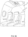
- the cabin 150 may include a system 152, or light source 152, that outputs a combination of UV and visible light 154.
- the system 152 and light 154 may be similar to the system 102 and light 104 of FIG. 1A .
- the system 102 may include at least one excimer lamp 200, at least one additional light source 206, a casing 216, and a cover 220.
- the excimer lamp 200 may include one or multiple excimer lamp elements. As shown, the at least one excimer lamp 200 includes four excimer lamp elements, including a first excimer lamp element 202 and a second excimer lamp element 204, which may be spaced apart.
- the excimer lamp 200 is designed to output excimer light which includes UV light having a wavelength that injures or kills pathogens (i.e., which disinfects, such as 222 nanometers) and further includes visible light as a byproduct.
- the visible light that is output by the excimer lamp 200 may have an undesirable color, may undesirably appear as arcing, or may have other undesirable properties.
- the at least one additional light source 206 may generate additional visible light that mixes with the visible light from the excimer lamp 200 to appear white or another desirable color, or to otherwise mask the light from the excimer lamp 200.
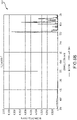
- a chart illustrates the visible light that is output by 222 nanometer excimer lamps.
- the visible light includes peaks around 400 nanometers (0.016 mils, which corresponds to a blue color) as well as peaks between 750 and 850 nanometers (0.030 mils and 0.033 mils, which corresponds to a red color).
- a chromaticity diagram 600 of FIG. 6A illustrates the various wavelengths and corresponding colors. In order to achieve a white color, an average of all wavelengths of light that will be mixed should be relatively close to a center 602 of the diagram 600.
- one way to achieve mask the visible light from an excimer lamp as white light is to combine a green or yellow-green color with the purple and red colors of visible light that is output by the excimer lamp.
- the at least one additional light source 206 may thus include one or more light source (e.g., first light source 208, second light source 210, and/or third light source 212) that each outputs light having a green or yellow-green color such that the visible light from the excimer lamp 200 and the at least one additional light source 206 appears white.
- the wavelength of the light that is output by the one or more light source 206 may also combine with the visible light of the excimer lamp to generate any other desirable color such as blue, green, or other lighting.
- Another way to mask the visible light from the excimer lamp 200 is to overpower the visible light from the excimer lamp by causing the at least one additional light source 206 to have a luminescence that is significantly greater, such as one or more order of magnitude greater, than a luminescence of the visible light that is output by the excimer lamp 200.
- the at least one additional light source 206 may include a white light source 214 that generates white visible light and has a luminescence that is significantly greater than the visible light that is output by the excimer lamp 200.
- the at least one additional light source 206 may include a plurality of light sources including a first light source 208, a second light source 210, and a third light source 212.
- the first, second, and third light sources 208, 210, 212 may each output visible light having a different wavelength.
- the color of light that is output by the first light source 208 may be red
- the color of light that is output by the second light source 210 may be green
- the color of light that is output by the third light source 212 may be blue.
- the light from the first, second, and third light sources 208, 210, 212 may mix with the visible light from the excimer lamp 200 to result in a white color.
- the intensity or other property of the light generated by the light sources 206 may be adjustable such that the system 102 may be designed to output light of multiple colors. For example, during certain times, the system 102 may be controlled to output white light, and at other times (e.g., when it is desirable for passengers to sleep), the system 102 may be controlled to output blue light, which is known to be soothing. As another example, during daytime the system 102 may be controlled to output light having a color temperature of 4,000 Kelvin, and during nighttime the system 102 may be controlled to output light having a color temperature of 2,700 Kelvin.
- the additional light sources 208, 210, 212 may be interspersed with the plurality of excimer lamps. That is, each additional light source 208, 210, 212 may be located between one or more of the excimer lamps (e.g., the third light source 212 may be located between the first and second excimer lamp elements 202, 204).
- the system 102 may further include a casing 216 having an outlet 218.
- the casing 216 may be formed from any material and may define a chamber.
- the excimer lamp 200 and the at least one additional light source 206 may each be housed in the chamber within the casing 216. That is, the additional light source 206 may be packaged with the excimer lamp 200. Combined light from the additional light source 206 and the excimer lamp 200 may be output via the outlet 218, as shown by an arrow 222.
- the system 102 may further include a cover 220 which covers the outlet 218.
- the cover 220 may be at least one of transparent or translucent to the UV light from the excimer lamp 200 as well as to the combination of visible light from the excimer lamp 200 and the at least one additional light source 206.
- the cover 220 may include a quartz glass and/or a sapphire crystal.
- the cover 220 may have a surface pattern that facilitates diffusion of the combined light from the excimer lamp 200 and the at least one additional light source 206.
- the surface pattern may be etched or otherwise formed into the material of the cover 220. This surface pattern (e.g., via the etching) may be formed in such a way as to diffuse the light from the excimer lamp 200 and from the at least one additional light source 206 to give the appearance of an opaque lens.
- the lavatory 300 may include an elongated system 302, or light source 302, that outputs a combination of UV and visible light 304.
- the system 302 and light 304 may be similar to the system 102 and light 104 of FIG. 1A except for the elongated shape of the system 302.
- an X-Y-Z axis is shown to illustrate the relative locations of the various elements.
- the system 302 may include an elongated excimer lamp 400.
- the excimer lamp 400 may have a longitudinal axis that extends along the X-axis.
- the excimer lamp 400 may generate or output similar excimer light as the excimer lamp 200 of FIG. 2 .
- the excimer lamp 400 may output disinfecting UV light along with visible light.
- it may be desirable to mask or otherwise hide the visible light generated by the excimer lamp 200.
- the elongated shape of the excimer lamp 400 allows for an elongated stream of light 304 to disinfect a relatively large surface.
- the system 302 may further include at least one additional light source 402 that outputs additional light in the visible spectrum.
- the at least one additional light source 402 may be designed such that a combination of the excimer light from the excimer lamp and the additional light from the additional light source appears white or another desirable color.
- the at least one additional light source 402 may have any of the properties as the at least one additional light source 206 of FIG. 2 .
- the at least one additional light source 402 may output light having a single wavelength that combines with the visible light from the excimer lamp 400 to appear white.
- the at least one additional light source 402 may have an intensity that is significantly greater than an intensity of the excimer lamp 400 such that the light from the additional light source 402 overpowers the light from the excimer lamp 400.
- the at least one additional light source 402 may include a plurality of additional light sources that each output light having a different wavelength such that a combination of light from all additional light sources and the excimer lamp 400 appear white (or another desirable color).
- the at least one additional light source 402 may include an array of additional light sources. Due to the elongated nature of the excimer lamp 400, the additional light sources 402 may be placed adjacent to each other along the X-axis such that they may extend along the length of the excimer lamp 400.
- the system 302 may further include an elongated casing 404.
- the casing 404 may define a cavity in which the excimer lamp 400 and the at least one additional light source 402 are located.
- the excimer lamp 400 and the at least one additional light source 402 may be mounted within the casing 404.
- the casing 404 may define an elongated outlet 406 through which a combination of the excimer light and the additional light exits the casing 404.
- a first portion of the casing 404 may include a first reflector 408 on an inner surface thereof, and a second portion of the casing 404 may include a second reflector 410 on an inner surface thereof.
- the first reflector 408 may be designed to reflect the excimer light from the excimer lamp 400 and the additional light from the additional light source 402 towards the second reflector 410.
- the first reflector 408 may have properties that facilitate reflection of light of all wavelengths that are generated by the excimer lamp 400 and the additional light source 402.
- the first reflector 408 may be formed using polytetrafluoroethylene (PTFE) or any other reflective material.
- the shape of the first reflector 408 may be designed such that the light from the excimer lamp 400 and the additional light source 402 are directed towards a desirable point on the second reflector 410.
- the second reflector 410 may be designed to reflect the excimer light from the excimer lamp 400 and the additional light from the additional light source 402 through the outlet 406 in a desirable orientation.
- the second reflector 410 may have properties that facilitate reflection of light of all wavelengths that are generated by the excimer lamp 400 and the additional light source 402.
- the second reflector 410 may be formed using PTFE.
- the second reflector 410 may be formed with a PTFE coating 412.
- the PTFE coating 412 may have properties that diffuse the light from the excimer lamp 400 and the additional light sources 402 such that all light from the system 302 is blended together upon exit from the outlet 406.
- the shape of the second reflector 410 may be designed such that the light from the excimer lamp 400 and the additional light source 402 are directed out of the outlet 406 in a desirable direction. In that regard, the shape of the second reflector 410 may be significantly different than the shape of the first reflector 408.
- FIG. 5A illustrates a plurality of excimer lamps 500 in a housing.
- the excimer lamps 500 each generate UV light and light having a visible wavelength or spectra.
- the visible light may undesirably appear as arcing.
- FIG. 5B illustrates a cover 520 with a diffused pattern thereon located on the excimer lamps 500. As shown, the arcing is difficult to make out, but the visible light from the excimer lamps 500 still appears as an undesirable color.
- FIG. 5C illustrates inclusion of an additional light source 540 (such as those described above) in addition to the cover 520. As shown, the light from the excimer lamps 500 and the additional light source 540, as viewed through the cover 520, appears as a soft white color.
- an additional light source 540 such as those described above
- the method 700 may include, in block 702, outputting excimer light that includes UV light and visible light.
- the method 700 may further include outputting, by at least one additional light source, additional visible light.
- the additional visible light may have a single wavelength that mixes with the visible light from the excimer lamp to achieve a desired color, may include multiple wavelengths that mix to form a desirable color (e.g., blue and red wavelengths may be mixed to appear purple, or the like), or white or other colored light having a luminescence that is significantly greater than that of the visible light from the excimer lamp.
- the method 700 further includes, in block 706, blending the excimer light and the visible light to improve a look of the excimer light.
- the excimer lamp and the additional light source may be co-located in a casing such that the light blends together.
- a cover with an etched pattern may be positioned at an outlet of the casing.
- reflectors may be included in the casing to diffuse and reflect the light from the excimer lamp and the additional light source.
- a controller may transmit power to a zone of a heating element in any of a number of manners.
- the controller may directly output a current or voltage signal to the zone.
- the controller may control a switch to open or close to cease or begin, respectively, application of a current or voltage signal to the zone.
- the controller may control a voltage or current source to output or cease outputting the current or voltage signal to the zone. Any other method of direct or indirect application or control of application of a power signal (e.g., voltage or current signal) to the zone is contemplated by the present disclosure.
Landscapes
- Health & Medical Sciences (AREA)
- Engineering & Computer Science (AREA)
- Physics & Mathematics (AREA)
- Life Sciences & Earth Sciences (AREA)
- Plasma & Fusion (AREA)
- Epidemiology (AREA)
- Electromagnetism (AREA)
- Animal Behavior & Ethology (AREA)
- General Health & Medical Sciences (AREA)
- Public Health (AREA)
- Veterinary Medicine (AREA)
- General Engineering & Computer Science (AREA)
- Apparatus For Disinfection Or Sterilisation (AREA)
- Non-Portable Lighting Devices Or Systems Thereof (AREA)
Abstract
Description
- The present disclosure relates to systems and methods for improving an appearance of light generated by an excimer lamp that outputs ultraviolet light.
- Ultraviolet (UV) light has been found to be an effective disinfectant. Of the various UV wavelengths, 222 nanometers (222 nm) has been found to be particularly promising (effective and safe for humans in moderate doses). Currently, UV lights that emit light of this wavelength are primarily available as gas-discharge excimer lamps. When active, these lamps output UV light having this desirable wavelength, but also output visible light that is viewed as a purple color to a human eye. The visible light also may appear as a plasma arc. Evidence supports the fact that this UV light is safe in occupied spaces, but a person unfamiliar with the technology may be concerned by the appearance of the visible light. Furthermore, it is also desirable to hide the excimer lamps from view in response to them being turned off.
- Disclosed herein is a system for improving an appearance of light from an excimer lamp. The system includes the excimer lamp configured to output excimer light that includes ultraviolet light having an ultraviolet wavelength and visible light having a first visible wavelength or spectra. The system further includes at least one additional light source configured to be packaged with the excimer lamp and to output additional light having a second visible wavelength or spectra. The system further includes a cover that is at least one of transparent or translucent to the ultraviolet wavelength and having a surface pattern that causes the excimer light to blend with the additional light.
- In any of the foregoing embodiments, the ultraviolet wavelength of the ultraviolet light that is output by the excimer lamp is between 200 and 225 nanometers.
- In any of the foregoing embodiments, the excimer lamp includes a plurality of excimer lamps spaced apart, and the at least one additional light source includes a plurality of additional light sources interspersed with the plurality of excimer lamps.
- In any of the foregoing embodiments, a combination of the excimer light and the additional light appears white to a human eye.
- In any of the foregoing embodiments, the second visible wavelength or spectra is selected to cause a combination of the visible light having the first visible wavelength or spectra and the additional light having the second visible wavelength or spectra to appear white to a human eye.
- In any of the foregoing embodiments, the at least one additional light source includes at least two additional light sources that each output the additional light having a different visible wavelength such that a combination of the additional light that is output by the at least two additional light sources appears white to a human eye.
- In any of the foregoing embodiments, a second luminescence of the additional light is at least one order of magnitude greater than a first luminesce of the visible light that is output by the excimer lamp so as to mask the visible light that is output by the excimer lamp.
- In any of the foregoing embodiments, the cover includes a quartz glass.
- In any of the foregoing embodiments, the quartz glass is etched to have the surface pattern.
- Also disclosed is a system for improving an appearance of light from an excimer lamp. The system includes the excimer lamp configured to output excimer light that includes ultraviolet light having an ultraviolet wavelength and visible light having a first visible wavelength or spectra. The system further includes at least one additional light source configured to be packaged with the excimer lamp and to output additional light having a second visible wavelength or spectra. The system further includes a casing having an outlet. The system further includes a first reflector configured to reflect the excimer light and the additional light towards the outlet. The system further includes a second reflector configured to reflect the excimer light and the additional light from the first reflector, from the excimer lamp, and from the at least one additional light source out of the outlet, the second reflector configured to reflect the ultraviolet light.
- In any of the foregoing embodiments, the second reflector has a polytetrafluoroethylene (PTFE) coating.
- In any of the foregoing embodiments, the excimer lamp and the casing each have an elongated shape, and the at least one additional light source includes an array of light sources spaced along a length of the casing.
- In any of the foregoing embodiments, the ultraviolet wavelength of the ultraviolet light that is output by the excimer lamp is between 200 and 225 nanometers.
- In any of the foregoing embodiments, a combination of the excimer light and the additional light appears white to a human eye.
- In any of the foregoing embodiments, the second visible wavelength or spectra is selected to cause a combination of the visible light having the first visible wavelength or spectra and the additional light having the second visible wavelength or spectra to appear white to a human eye.
- In any of the foregoing embodiments, the at least one additional light source includes at least two additional light sources that each output the additional light having a different visible wavelength such that a combination of the additional light that is output by the at least two additional light sources appears white to a human eye.
- In any of the foregoing embodiments, a second luminescence of the additional light is at least one order of magnitude greater than a first luminesce of the visible light that is output by the excimer lamp so as to mask the visible light that is output by the excimer lamp.
- Also disclosed is a method for improving an appearance of light from an excimer lamp. The method includes outputting, by the excimer lamp, excimer light that includes ultraviolet light having an ultraviolet wavelength and visible light having a first visible wavelength or spectra. The method further includes outputting, by at least one additional light source, additional light having a second visible wavelength or spectra. The method further includes blending the excimer light with the additional light to hide the visible light having the first visible wavelength or spectra that is output by the excimer lamp.
- In any of the foregoing embodiments, blending the excimer light with the additional light includes diffusing, by a quartz glass cover, the excimer light and the additional light.
- In any of the foregoing embodiments, blending the excimer light with the additional light includes blending, using at least one reflector configured to reflect the excimer light, the excimer light and the additional light prior to a combination of the excimer light and the additional light leaving an outlet.
- The foregoing features and elements may be combined in various combinations without exclusivity, unless expressly indicated otherwise. These features and elements as well as the operation thereof will become more apparent in light of the following description and the accompanying drawings. It should be understood, however, the following description and drawings are intended to be exemplary in nature and non-limiting.
- The subject matter of the present disclosure is particularly pointed out and distinctly claimed in the concluding portion of the specification. A more complete understanding of the present disclosure, however, may best be obtained by referring to the detailed description and claims when considered in connection with the figures, wherein like numerals denote like elements.
-
FIG. 1A illustrates an aircraft lavatory having a system for improving an appearance of light from an excimer lamp, in accordance with various embodiments; -
FIG. 1B illustrates a portion of an aircraft cabin having a system for improving an appearance of light from an excimer lamp, in accordance with various embodiments; -
FIG. 2 illustrates various features of the system ofFIG. 1A , in accordance with various embodiments; -
FIG. 3 illustrates a portion of an aircraft lavatory having a system for improving an appearance of light from an excimer lamp, in accordance with various embodiments; -
FIG. 4A illustrates various features of the system ofFIG. 3 , in accordance with various embodiments; -
FIG. 4B illustrates an elongated excimer lamp of the system ofFIG. 3 , in accordance with various embodiments; -
FIGS. 5A, 5B, and 5C illustrate an effect of various features of a system for improving an appearance of light from an excimer lamp, in accordance with various embodiments; -
FIG. 6A illustrates a chromaticity diagram, in accordance with various embodiments; -
FIG. 6B illustrates a chart showing wavelengths of visible light that are generated by an ultraviolet excimer lamp, in accordance with various embodiments; and -
FIG. 7 is a flowchart illustrating a method for improving an appearance of light from an excimer lamp, in accordance with various embodiments. - The detailed description of exemplary embodiments herein makes reference to the accompanying drawings, which show exemplary embodiments by way of illustration. While these exemplary embodiments are described in sufficient detail to enable those skilled in the art to practice the exemplary embodiments of the disclosure, it should be understood that other embodiments may be realized and that logical changes and adaptations in design and construction may be made in accordance with this disclosure and the teachings herein. Thus, the detailed description herein is presented for purposes of illustration only and not limitation. The steps recited in any of the method or process descriptions may be executed in any order and are not necessarily limited to the order presented.
- Furthermore, any reference to singular includes plural embodiments, and any reference to more than one component or step may include a singular embodiment or step. Also, any reference to attached, fixed, connected or the like may include permanent, removable, temporary, partial, full and/or any other possible attachment option. Additionally, any reference to without contact (or similar phrases) may also include reduced contact or minimal contact. Surface shading lines may be used throughout the figures to denote different parts but not necessarily to denote the same or different materials.
- Referring now to
FIG. 1A , a portion of anaircraft lavatory 100 is shown. Thelavatory 100 includes asystem 102, orlight source 102, that outputs a combination of light 104 that includes ultraviolet (UV) light and visible light. Where used herein, UV light may refer to light that is visible to living eyes or invisible to living eyes. In that regard, the phrase "UV light" may be replaced with "UV radiation." The UV light may have a wavelength that is designed to injure or kill pathogens. For example, the wavelength may be between 200 and 225 nanometers (0.0079 thousandths of an inch, or mils, and 0.0088 mils), between 220 and 225 nanometers (0.0087 mils and 0.0088 mils), or about 222 nanometers (0.0087 mils). Where used in this context, about refers to the referenced value plus or minus 2 percent of the referenced value. The light 104 from thesystem 102 may be directed towards a portion of thelavatory 100 for which disinfecting is desirable. - Referring now to
FIG. 1B , a portion of anaircraft cabin 150 is shown. Thecabin 150 may include asystem 152, orlight source 152, that outputs a combination of UV andvisible light 154. Thesystem 152 and light 154 may be similar to thesystem 102 andlight 104 ofFIG. 1A . - Turning to
FIG. 2 , additional details of thesystem 102 orsystem 152 ofFIG. 1A orFIG. 1B is shown. In particular, thesystem 102 may include at least oneexcimer lamp 200, at least one additionallight source 206, acasing 216, and acover 220. - The
excimer lamp 200 may include one or multiple excimer lamp elements. As shown, the at least oneexcimer lamp 200 includes four excimer lamp elements, including a firstexcimer lamp element 202 and a secondexcimer lamp element 204, which may be spaced apart. Theexcimer lamp 200 is designed to output excimer light which includes UV light having a wavelength that injures or kills pathogens (i.e., which disinfects, such as 222 nanometers) and further includes visible light as a byproduct. The visible light that is output by theexcimer lamp 200 may have an undesirable color, may undesirably appear as arcing, or may have other undesirable properties. - It is desirable to mask, occlude, or otherwise hide the visible light that is generated by the
excimer lamp 200 while still achieving the disinfecting effect of the UV light from theexcimer lamp 200. In that regard, the at least one additionallight source 206 may generate additional visible light that mixes with the visible light from theexcimer lamp 200 to appear white or another desirable color, or to otherwise mask the light from theexcimer lamp 200. - For example, and referring briefly to
FIGS. 6A and6B , a chart illustrates the visible light that is output by 222 nanometer excimer lamps. As shown, the visible light includes peaks around 400 nanometers (0.016 mils, which corresponds to a blue color) as well as peaks between 750 and 850 nanometers (0.030 mils and 0.033 mils, which corresponds to a red color). A chromaticity diagram 600 ofFIG. 6A illustrates the various wavelengths and corresponding colors. In order to achieve a white color, an average of all wavelengths of light that will be mixed should be relatively close to acenter 602 of the diagram 600. Thus, one way to achieve mask the visible light from an excimer lamp as white light is to combine a green or yellow-green color with the purple and red colors of visible light that is output by the excimer lamp. - Returning reference to
FIG. 2 , the at least one additionallight source 206 may thus include one or more light source (e.g., firstlight source 208, secondlight source 210, and/or third light source 212) that each outputs light having a green or yellow-green color such that the visible light from theexcimer lamp 200 and the at least one additionallight source 206 appears white. The wavelength of the light that is output by the one or morelight source 206 may also combine with the visible light of the excimer lamp to generate any other desirable color such as blue, green, or other lighting. - Another way to mask the visible light from the
excimer lamp 200 is to overpower the visible light from the excimer lamp by causing the at least one additionallight source 206 to have a luminescence that is significantly greater, such as one or more order of magnitude greater, than a luminescence of the visible light that is output by theexcimer lamp 200. For example, the at least one additionallight source 206 may include awhite light source 214 that generates white visible light and has a luminescence that is significantly greater than the visible light that is output by theexcimer lamp 200. - In various embodiments, the at least one additional
light source 206 may include a plurality of light sources including a firstlight source 208, a secondlight source 210, and a thirdlight source 212. The first, second, and thirdlight sources light source 208 may be red, the color of light that is output by the secondlight source 210 may be green, and the color of light that is output by the thirdlight source 212 may be blue. The light from the first, second, and thirdlight sources excimer lamp 200 to result in a white color. In various embodiments, the intensity or other property of the light generated by thelight sources 206 may be adjustable such that thesystem 102 may be designed to output light of multiple colors. For example, during certain times, thesystem 102 may be controlled to output white light, and at other times (e.g., when it is desirable for passengers to sleep), thesystem 102 may be controlled to output blue light, which is known to be soothing. As another example, during daytime thesystem 102 may be controlled to output light having a color temperature of 4,000 Kelvin, and during nighttime thesystem 102 may be controlled to output light having a color temperature of 2,700 Kelvin. - In embodiments in which the
excimer lamp 200 includes a plurality of excimer lamps, the additionallight sources light source light source 212 may be located between the first and secondexcimer lamp elements 202, 204). - The
system 102 may further include acasing 216 having anoutlet 218. Thecasing 216 may be formed from any material and may define a chamber. Theexcimer lamp 200 and the at least one additionallight source 206 may each be housed in the chamber within thecasing 216. That is, the additionallight source 206 may be packaged with theexcimer lamp 200. Combined light from the additionallight source 206 and theexcimer lamp 200 may be output via theoutlet 218, as shown by anarrow 222. - The
system 102 may further include acover 220 which covers theoutlet 218. Thecover 220 may be at least one of transparent or translucent to the UV light from theexcimer lamp 200 as well as to the combination of visible light from theexcimer lamp 200 and the at least one additionallight source 206. For example, thecover 220 may include a quartz glass and/or a sapphire crystal. In addition, thecover 220 may have a surface pattern that facilitates diffusion of the combined light from theexcimer lamp 200 and the at least one additionallight source 206. For example, the surface pattern may be etched or otherwise formed into the material of thecover 220. This surface pattern (e.g., via the etching) may be formed in such a way as to diffuse the light from theexcimer lamp 200 and from the at least one additionallight source 206 to give the appearance of an opaque lens. - Referring now to
FIG. 3 , a portion of anaircraft lavatory 300 is shown. Thelavatory 300 may include anelongated system 302, orlight source 302, that outputs a combination of UV andvisible light 304. Thesystem 302 and light 304 may be similar to thesystem 102 andlight 104 ofFIG. 1A except for the elongated shape of thesystem 302. - Referring to
FIGS. 3 ,4A , and4B , an X-Y-Z axis is shown to illustrate the relative locations of the various elements. - In particular, the
system 302 may include anelongated excimer lamp 400. Theexcimer lamp 400 may have a longitudinal axis that extends along the X-axis. Theexcimer lamp 400 may generate or output similar excimer light as theexcimer lamp 200 ofFIG. 2 . In particular theexcimer lamp 400 may output disinfecting UV light along with visible light. As with theexcimer lamp 200 ofFIG. 2 , it may be desirable to mask or otherwise hide the visible light generated by theexcimer lamp 200. The elongated shape of theexcimer lamp 400 allows for an elongated stream of light 304 to disinfect a relatively large surface. - The
system 302 may further include at least one additionallight source 402 that outputs additional light in the visible spectrum. The at least one additionallight source 402 may be designed such that a combination of the excimer light from the excimer lamp and the additional light from the additional light source appears white or another desirable color. - The at least one additional
light source 402 may have any of the properties as the at least one additionallight source 206 ofFIG. 2 . For example, the at least one additionallight source 402 may output light having a single wavelength that combines with the visible light from theexcimer lamp 400 to appear white. As another example, the at least one additionallight source 402 may have an intensity that is significantly greater than an intensity of theexcimer lamp 400 such that the light from the additionallight source 402 overpowers the light from theexcimer lamp 400. As yet another example, the at least one additionallight source 402 may include a plurality of additional light sources that each output light having a different wavelength such that a combination of light from all additional light sources and theexcimer lamp 400 appear white (or another desirable color). - In various embodiments, the at least one additional
light source 402 may include an array of additional light sources. Due to the elongated nature of theexcimer lamp 400, the additionallight sources 402 may be placed adjacent to each other along the X-axis such that they may extend along the length of theexcimer lamp 400. - The
system 302 may further include anelongated casing 404. Thecasing 404 may define a cavity in which theexcimer lamp 400 and the at least one additionallight source 402 are located. For example, theexcimer lamp 400 and the at least one additionallight source 402 may be mounted within thecasing 404. Thecasing 404 may define anelongated outlet 406 through which a combination of the excimer light and the additional light exits thecasing 404. - A first portion of the
casing 404 may include afirst reflector 408 on an inner surface thereof, and a second portion of thecasing 404 may include asecond reflector 410 on an inner surface thereof. Thefirst reflector 408 may be designed to reflect the excimer light from theexcimer lamp 400 and the additional light from the additionallight source 402 towards thesecond reflector 410. In that regard, thefirst reflector 408 may have properties that facilitate reflection of light of all wavelengths that are generated by theexcimer lamp 400 and the additionallight source 402. For example, thefirst reflector 408 may be formed using polytetrafluoroethylene (PTFE) or any other reflective material. The shape of thefirst reflector 408 may be designed such that the light from theexcimer lamp 400 and the additionallight source 402 are directed towards a desirable point on thesecond reflector 410. - The
second reflector 410 may be designed to reflect the excimer light from theexcimer lamp 400 and the additional light from the additionallight source 402 through theoutlet 406 in a desirable orientation. In that regard, thesecond reflector 410 may have properties that facilitate reflection of light of all wavelengths that are generated by theexcimer lamp 400 and the additionallight source 402. For example, thesecond reflector 410 may be formed using PTFE. In that regard, thesecond reflector 410 may be formed with aPTFE coating 412. ThePTFE coating 412 may have properties that diffuse the light from theexcimer lamp 400 and the additionallight sources 402 such that all light from thesystem 302 is blended together upon exit from theoutlet 406. The shape of thesecond reflector 410 may be designed such that the light from theexcimer lamp 400 and the additionallight source 402 are directed out of theoutlet 406 in a desirable direction. In that regard, the shape of thesecond reflector 410 may be significantly different than the shape of thefirst reflector 408. - Turning to
FIGS. 5A, 5B, and 5C , implementation of a system for improving an appearance of light from an excimer lamp is shown.FIG. 5A illustrates a plurality ofexcimer lamps 500 in a housing. Theexcimer lamps 500 each generate UV light and light having a visible wavelength or spectra. The visible light may undesirably appear as arcing. -
FIG. 5B illustrates acover 520 with a diffused pattern thereon located on theexcimer lamps 500. As shown, the arcing is difficult to make out, but the visible light from theexcimer lamps 500 still appears as an undesirable color. -
FIG. 5C illustrates inclusion of an additional light source 540 (such as those described above) in addition to thecover 520. As shown, the light from theexcimer lamps 500 and the additionallight source 540, as viewed through thecover 520, appears as a soft white color. - Turning to
FIG. 7 , amethod 700 for improving an appearance of light from an excimer lamp is shown. Themethod 700 may include, inblock 702, outputting excimer light that includes UV light and visible light. Themethod 700 may further include outputting, by at least one additional light source, additional visible light. The additional visible light may have a single wavelength that mixes with the visible light from the excimer lamp to achieve a desired color, may include multiple wavelengths that mix to form a desirable color (e.g., blue and red wavelengths may be mixed to appear purple, or the like), or white or other colored light having a luminescence that is significantly greater than that of the visible light from the excimer lamp. - The
method 700 further includes, inblock 706, blending the excimer light and the visible light to improve a look of the excimer light. For example, the excimer lamp and the additional light source may be co-located in a casing such that the light blends together. As another example, a cover with an etched pattern may be positioned at an outlet of the casing. As yet another example, reflectors may be included in the casing to diffuse and reflect the light from the excimer lamp and the additional light source. - Where used in the context above, a controller may transmit power to a zone of a heating element in any of a number of manners. For example, the controller may directly output a current or voltage signal to the zone. As another example, the controller may control a switch to open or close to cease or begin, respectively, application of a current or voltage signal to the zone. As yet another example, the controller may control a voltage or current source to output or cease outputting the current or voltage signal to the zone. Any other method of direct or indirect application or control of application of a power signal (e.g., voltage or current signal) to the zone is contemplated by the present disclosure.
- Benefits and other advantages have been described herein with regard to specific embodiments. Furthermore, the connecting lines shown in the various figures contained herein are intended to represent exemplary functional relationships and/or physical couplings between the various elements. It should be noted that many alternative or additional functional relationships or physical connections may be present in a practical system. However, the benefits, advantages, and any elements that may cause any benefit or advantage to occur or become more pronounced are not to be construed as critical, required, or essential features or elements of the disclosure. The scope of the disclosure is accordingly to be limited by nothing other than the appended claims.
Claims (15)
- A system for improving an appearance of light from an excimer lamp, the system comprising:the excimer lamp (200) configured to output excimer light that includes ultraviolet light having an ultraviolet wavelength and visible light having a first visible wavelength or spectra;at least one additional light source (206) configured to be packaged with the excimer lamp and to output additional light having a second visible wavelength or spectra; anda cover (220) that is at least one of transparent or translucent to the ultraviolet wavelength and having a surface pattern that causes the excimer light to blend with the additional light.
- The system of claim 1, wherein the excimer lamp includes a plurality of excimer lamps (220, 204) spaced apart, and the at least one additional light source includes a plurality of additional light sources (208, 210, 212) interspersed with the plurality of excimer lamps.
- The system of claim 1 or 2, wherein the cover (220) includes a quartz glass.
- The system of claim 3, wherein the quartz glass is etched to have the surface pattern.
- A system for improving an appearance of light from an excimer lamp, the system comprising:the excimer lamp (200) configured to output excimer light that includes ultraviolet light having an ultraviolet wavelength and visible light having a first visible wavelength or spectra;at least one additional light source (206) configured to be packaged with the excimer lamp and to output additional light having a second visible wavelength or spectra;a casing (216) having an outlet (218);a first reflector (408) configured to reflect the excimer light and the additional light towards the outlet; anda second reflector (410) configured to reflect the excimer light and the additional light from the first reflector, from the excimer lamp, and from the at least one additional light source out of the outlet, the second reflector configured to reflect the ultraviolet light.
- The system of claim 5, wherein the second reflector has a polytetrafluoroethylene, PTFE, coating.
- The system of claim 5 or 6, wherein the excimer lamp and the casing each have an elongated shape, and the at least one additional light source includes an array of light sources spaced along a length of the casing.
- The system of any preceding claim, wherein the ultraviolet wavelength of the ultraviolet light that is output by the excimer lamp is between 200 and 225 nanometers.
- The system of any preceding claim, wherein a combination of the excimer light and the additional light appears white to a human eye.
- The system of any preceding claim, wherein the second visible wavelength or spectra is selected to cause a combination of the visible light having the first visible wavelength or spectra and the additional light having the second visible wavelength or spectra to appear white to a human eye.
- The system of any of claims 1 to 9, wherein the at least one additional light source includes at least two additional light sources (208, 210, 212) that each output the additional light having a different visible wavelength such that a combination of the additional light that is output by the at least two additional light sources appears white to a human eye.
- The system of any preceding claim, wherein a second luminescence of the additional light is at least one order of magnitude greater than a first luminesce of the visible light that is output by the excimer lamp so as to mask the visible light that is output by the excimer lamp.
- A method for improving an appearance of light from an excimer lamp, the method comprising:outputting, by the excimer lamp, excimer light that includes ultraviolet light having an ultraviolet wavelength and visible light having a first visible wavelength or spectra;outputting, by at least one additional light source, additional light having a second visible wavelength or spectra; andblending the excimer light with the additional light to hide the visible light having the first visible wavelength or spectra that is output by the excimer lamp.
- The method of claim 13, wherein blending the excimer light with the additional light includes diffusing, by a quartz glass cover, the excimer light and the additional light.
- The method of claim 13, wherein blending the excimer light with the additional light includes blending, using at least one reflector configured to reflect the excimer light, the excimer light and the additional light prior to a combination of the excimer light and the additional light leaving an outlet.
Applications Claiming Priority (2)
| Application Number | Priority Date | Filing Date | Title |
|---|---|---|---|
| US202163189951P | 2021-05-18 | 2021-05-18 | |
| US17/736,358 US12106956B2 (en) | 2021-05-18 | 2022-05-04 | Color mixed excimer lamp for soft glow effect |
Publications (1)
| Publication Number | Publication Date |
|---|---|
| EP4092319A1 true EP4092319A1 (en) | 2022-11-23 |
Family
ID=81984588
Family Applications (1)
| Application Number | Title | Priority Date | Filing Date |
|---|---|---|---|
| EP22174109.3A Pending EP4092319A1 (en) | 2021-05-18 | 2022-05-18 | Color mixed excimer lamp for soft glow effect |
Country Status (2)
| Country | Link |
|---|---|
| US (1) | US12106956B2 (en) |
| EP (1) | EP4092319A1 (en) |
Families Citing this family (1)
| Publication number | Priority date | Publication date | Assignee | Title |
|---|---|---|---|---|
| US20230001029A1 (en) * | 2021-07-01 | 2023-01-05 | Vyv, Inc. | Combined Light Disinfection Device |
Citations (3)
| Publication number | Priority date | Publication date | Assignee | Title |
|---|---|---|---|---|
| DE202020001197U1 (en) * | 2020-03-26 | 2020-04-15 | Digitalicht Ag | Lighting device with integrated UVC radiation source |
| WO2020121934A1 (en) * | 2018-12-14 | 2020-06-18 | ウシオ電機株式会社 | Uv irradiation apparatus |
| US20200215214A1 (en) * | 2018-02-20 | 2020-07-09 | Freestyle Partners, LLC | Portable and disposable uv device |
Family Cites Families (11)
| Publication number | Priority date | Publication date | Assignee | Title |
|---|---|---|---|---|
| US6211383B1 (en) * | 1993-08-05 | 2001-04-03 | Kimberly-Clark Worldwide, Inc. | Nohr-McDonald elimination reaction |
| US7863816B2 (en) * | 2003-10-23 | 2011-01-04 | General Electric Company | Dielectric barrier discharge lamp |
| US20070045641A1 (en) | 2005-08-23 | 2007-03-01 | Yin Chua Janet B | Light source with UV LED and UV reflector |
| US20070053188A1 (en) | 2005-09-06 | 2007-03-08 | Luminator Holding, L.P. | LED ultraviolet air sanitizer light fixture |
| US9974138B2 (en) * | 2015-04-21 | 2018-05-15 | GE Lighting Solutions, LLC | Multi-channel lamp system and method with mixed spectrum |
| US10551032B2 (en) * | 2015-07-23 | 2020-02-04 | Signify Holding B.V. | Lighting assembly with a UV protected light source that emits visible light |
| US10655818B2 (en) | 2017-01-24 | 2020-05-19 | The Boeing Company | Light-converting lighting assembly |
| US10413626B1 (en) * | 2018-03-29 | 2019-09-17 | Vital Vio, Inc. | Multiple light emitter for inactivating microorganisms |
| US11006493B1 (en) | 2018-05-29 | 2021-05-11 | Juganu Ltd. | Lighting systems for general illumination and disinfection |
| US20200038542A1 (en) | 2018-08-06 | 2020-02-06 | Skizukesa Technologies LLC | Method for economically disinfecting air using light fixtures |
| US11628234B2 (en) * | 2020-06-01 | 2023-04-18 | Know Labs, Inc. | White light LED light bulbs for ambient lighting and pathogen inactivation |
-
2022
- 2022-05-04 US US17/736,358 patent/US12106956B2/en active Active
- 2022-05-18 EP EP22174109.3A patent/EP4092319A1/en active Pending
Patent Citations (3)
| Publication number | Priority date | Publication date | Assignee | Title |
|---|---|---|---|---|
| US20200215214A1 (en) * | 2018-02-20 | 2020-07-09 | Freestyle Partners, LLC | Portable and disposable uv device |
| WO2020121934A1 (en) * | 2018-12-14 | 2020-06-18 | ウシオ電機株式会社 | Uv irradiation apparatus |
| DE202020001197U1 (en) * | 2020-03-26 | 2020-04-15 | Digitalicht Ag | Lighting device with integrated UVC radiation source |
Also Published As
| Publication number | Publication date |
|---|---|
| US20220375741A1 (en) | 2022-11-24 |
| US12106956B2 (en) | 2024-10-01 |
Similar Documents
| Publication | Publication Date | Title |
|---|---|---|
| JP6802803B2 (en) | Multi-channel lamp system and method using mixed spectrum | |
| CN114731748B (en) | LED filaments and LED filament lamps | |
| CN110024141B (en) | Illumination system with reduced spectral content of melanopsin | |
| JP6396609B2 (en) | Lighting assembly that emits part of UV light | |
| CN105830216B (en) | Light emitting module, lamp, lighting device and the method for irradiating object | |
| US7160012B2 (en) | Lamp | |
| JP2005534155A (en) | Lamp system comprising a green-blue gas discharge lamp and a yellow-red LED | |
| KR20150098175A (en) | Lighting device | |
| CN104854398A (en) | Lighting equipment for illuminating illuminated areas | |
| JP2015221655A (en) | In-cabin lighting device | |
| US12106956B2 (en) | Color mixed excimer lamp for soft glow effect | |
| JP2007299714A (en) | lighting equipment | |
| WO2022152641A1 (en) | Lighting arrangement for illumination and disinfection lighting | |
| WO2024146805A1 (en) | Led filament comprising leds arranged to emit nir light | |
| CN105378375A (en) | LED module, luminaire comprising the same and method for influencing light spectrum | |
| EP4538588B1 (en) | Led filament arrangement | |
| JP7026774B2 (en) | Use of light emitting parts, lamps and lamps and light emitting parts | |
| JP7159743B2 (en) | Lighting device and light irradiation method | |
| EP4295648B1 (en) | A light generating device having improved performance for disinfection and general lighting | |
| CN120769963A (en) | LED filament device comprising individually controlled LEDs | |
| Menkara | Spectral Tailoring Using Solid-State Lighting Phosphors | |
| JPH0921964A (en) | Light source for magnifying observation device | |
| WO2023131551A1 (en) | Led filament for illumination and disinfection | |
| CN119403577A (en) | LED filament comprising LEDs arranged to emit violet and ultraviolet light | |
| JP2005271632A (en) | Interior lighting |
Legal Events
| Date | Code | Title | Description |
|---|---|---|---|
| PUAI | Public reference made under article 153(3) epc to a published international application that has entered the european phase |
Free format text: ORIGINAL CODE: 0009012 |
|
| STAA | Information on the status of an ep patent application or granted ep patent |
Free format text: STATUS: THE APPLICATION HAS BEEN PUBLISHED |
|
| AK | Designated contracting states |
Kind code of ref document: A1 Designated state(s): AL AT BE BG CH CY CZ DE DK EE ES FI FR GB GR HR HU IE IS IT LI LT LU LV MC MK MT NL NO PL PT RO RS SE SI SK SM TR |
|
| STAA | Information on the status of an ep patent application or granted ep patent |
Free format text: STATUS: REQUEST FOR EXAMINATION WAS MADE |
|
| 17P | Request for examination filed |
Effective date: 20230523 |
|
| RBV | Designated contracting states (corrected) |
Designated state(s): AL AT BE BG CH CY CZ DE DK EE ES FI FR GB GR HR HU IE IS IT LI LT LU LV MC MK MT NL NO PL PT RO RS SE SI SK SM TR |
|
| P01 | Opt-out of the competence of the unified patent court (upc) registered |
Effective date: 20230922 |
|
| RIC1 | Information provided on ipc code assigned before grant |
Ipc: B64D 47/02 20060101ALN20250312BHEP Ipc: F21Y 113/10 20160101ALN20250312BHEP Ipc: F21Y 113/20 20160101ALN20250312BHEP Ipc: F21S 8/02 20060101ALI20250312BHEP Ipc: A61L 9/20 20060101ALI20250312BHEP Ipc: F21V 3/04 20180101ALI20250312BHEP Ipc: F21V 33/00 20060101AFI20250312BHEP |
|
| RIC1 | Information provided on ipc code assigned before grant |
Ipc: B64D 47/02 20060101ALN20250327BHEP Ipc: F21Y 113/10 20160101ALN20250327BHEP Ipc: F21Y 113/20 20160101ALN20250327BHEP Ipc: F21S 8/02 20060101ALI20250327BHEP Ipc: A61L 9/20 20060101ALI20250327BHEP Ipc: F21V 3/04 20180101ALI20250327BHEP Ipc: F21V 33/00 20060101AFI20250327BHEP |
|
| STAA | Information on the status of an ep patent application or granted ep patent |
Free format text: STATUS: EXAMINATION IS IN PROGRESS |
|
| 17Q | First examination report despatched |
Effective date: 20250519 |