EP4092283A1 - Winding method for radial magnetic bearing stator, radial magnetic bearing stator and radial magnetic bearing - Google Patents
Winding method for radial magnetic bearing stator, radial magnetic bearing stator and radial magnetic bearing Download PDFInfo
- Publication number
- EP4092283A1 EP4092283A1 EP22174432.9A EP22174432A EP4092283A1 EP 4092283 A1 EP4092283 A1 EP 4092283A1 EP 22174432 A EP22174432 A EP 22174432A EP 4092283 A1 EP4092283 A1 EP 4092283A1
- Authority
- EP
- European Patent Office
- Prior art keywords
- stator
- winding
- magnetic bearing
- coil
- radial magnetic
- Prior art date
- Legal status (The legal status is an assumption and is not a legal conclusion. Google has not performed a legal analysis and makes no representation as to the accuracy of the status listed.)
- Granted
Links
Images
Classifications
-
- F—MECHANICAL ENGINEERING; LIGHTING; HEATING; WEAPONS; BLASTING
- F16—ENGINEERING ELEMENTS AND UNITS; GENERAL MEASURES FOR PRODUCING AND MAINTAINING EFFECTIVE FUNCTIONING OF MACHINES OR INSTALLATIONS; THERMAL INSULATION IN GENERAL
- F16C—SHAFTS; FLEXIBLE SHAFTS; ELEMENTS OR CRANKSHAFT MECHANISMS; ROTARY BODIES OTHER THAN GEARING ELEMENTS; BEARINGS
- F16C32/00—Bearings not otherwise provided for
- F16C32/04—Bearings not otherwise provided for using magnetic or electric supporting means
- F16C32/0406—Magnetic bearings
- F16C32/044—Active magnetic bearings
- F16C32/047—Details of housings; Mounting of active magnetic bearings
-
- F—MECHANICAL ENGINEERING; LIGHTING; HEATING; WEAPONS; BLASTING
- F16—ENGINEERING ELEMENTS AND UNITS; GENERAL MEASURES FOR PRODUCING AND MAINTAINING EFFECTIVE FUNCTIONING OF MACHINES OR INSTALLATIONS; THERMAL INSULATION IN GENERAL
- F16C—SHAFTS; FLEXIBLE SHAFTS; ELEMENTS OR CRANKSHAFT MECHANISMS; ROTARY BODIES OTHER THAN GEARING ELEMENTS; BEARINGS
- F16C32/00—Bearings not otherwise provided for
- F16C32/04—Bearings not otherwise provided for using magnetic or electric supporting means
- F16C32/0406—Magnetic bearings
- F16C32/044—Active magnetic bearings
- F16C32/0459—Details of the magnetic circuit
- F16C32/0461—Details of the magnetic circuit of stationary parts of the magnetic circuit
-
- F—MECHANICAL ENGINEERING; LIGHTING; HEATING; WEAPONS; BLASTING
- F16—ENGINEERING ELEMENTS AND UNITS; GENERAL MEASURES FOR PRODUCING AND MAINTAINING EFFECTIVE FUNCTIONING OF MACHINES OR INSTALLATIONS; THERMAL INSULATION IN GENERAL
- F16C—SHAFTS; FLEXIBLE SHAFTS; ELEMENTS OR CRANKSHAFT MECHANISMS; ROTARY BODIES OTHER THAN GEARING ELEMENTS; BEARINGS
- F16C32/00—Bearings not otherwise provided for
- F16C32/04—Bearings not otherwise provided for using magnetic or electric supporting means
- F16C32/0406—Magnetic bearings
- F16C32/044—Active magnetic bearings
- F16C32/0474—Active magnetic bearings for rotary movement
- F16C32/048—Active magnetic bearings for rotary movement with active support of two degrees of freedom, e.g. radial magnetic bearings
-
- F—MECHANICAL ENGINEERING; LIGHTING; HEATING; WEAPONS; BLASTING
- F16—ENGINEERING ELEMENTS AND UNITS; GENERAL MEASURES FOR PRODUCING AND MAINTAINING EFFECTIVE FUNCTIONING OF MACHINES OR INSTALLATIONS; THERMAL INSULATION IN GENERAL
- F16C—SHAFTS; FLEXIBLE SHAFTS; ELEMENTS OR CRANKSHAFT MECHANISMS; ROTARY BODIES OTHER THAN GEARING ELEMENTS; BEARINGS
- F16C32/00—Bearings not otherwise provided for
- F16C32/04—Bearings not otherwise provided for using magnetic or electric supporting means
- F16C32/0406—Magnetic bearings
- F16C32/044—Active magnetic bearings
-
- H—ELECTRICITY
- H01—ELECTRIC ELEMENTS
- H01F—MAGNETS; INDUCTANCES; TRANSFORMERS; SELECTION OF MATERIALS FOR THEIR MAGNETIC PROPERTIES
- H01F41/00—Apparatus or processes specially adapted for manufacturing or assembling magnets, inductances or transformers; Apparatus or processes specially adapted for manufacturing materials characterised by their magnetic properties
- H01F41/02—Apparatus or processes specially adapted for manufacturing or assembling magnets, inductances or transformers; Apparatus or processes specially adapted for manufacturing materials characterised by their magnetic properties for manufacturing cores, coils, or magnets
- H01F41/04—Apparatus or processes specially adapted for manufacturing or assembling magnets, inductances or transformers; Apparatus or processes specially adapted for manufacturing materials characterised by their magnetic properties for manufacturing cores, coils, or magnets for manufacturing coils
- H01F41/06—Coil winding
- H01F41/098—Mandrels; Formers
-
- H—ELECTRICITY
- H01—ELECTRIC ELEMENTS
- H01F—MAGNETS; INDUCTANCES; TRANSFORMERS; SELECTION OF MATERIALS FOR THEIR MAGNETIC PROPERTIES
- H01F5/00—Coils
- H01F5/02—Coils wound on non-magnetic supports, e.g. formers
-
- H—ELECTRICITY
- H02—GENERATION; CONVERSION OR DISTRIBUTION OF ELECTRIC POWER
- H02K—DYNAMO-ELECTRIC MACHINES
- H02K1/00—Details of the magnetic circuit
- H02K1/06—Details of the magnetic circuit characterised by the shape, form or construction
- H02K1/12—Stationary parts of the magnetic circuit
- H02K1/14—Stator cores with salient poles
- H02K1/146—Stator cores with salient poles consisting of a generally annular yoke with salient poles
-
- H—ELECTRICITY
- H02—GENERATION; CONVERSION OR DISTRIBUTION OF ELECTRIC POWER
- H02K—DYNAMO-ELECTRIC MACHINES
- H02K3/00—Details of windings
- H02K3/04—Windings characterised by the conductor shape, form or construction, e.g. with bar conductors
- H02K3/28—Layout of windings or of connections between windings
-
- H—ELECTRICITY
- H02—GENERATION; CONVERSION OR DISTRIBUTION OF ELECTRIC POWER
- H02K—DYNAMO-ELECTRIC MACHINES
- H02K3/00—Details of windings
- H02K3/46—Fastening of windings on the stator or rotor structure
- H02K3/48—Fastening of windings on the stator or rotor structure in slots
-
- H—ELECTRICITY
- H02—GENERATION; CONVERSION OR DISTRIBUTION OF ELECTRIC POWER
- H02K—DYNAMO-ELECTRIC MACHINES
- H02K3/00—Details of windings
- H02K3/46—Fastening of windings on the stator or rotor structure
- H02K3/52—Fastening salient pole windings or connections thereto
- H02K3/521—Fastening salient pole windings or connections thereto applicable to stators only
- H02K3/522—Fastening salient pole windings or connections thereto applicable to stators only for generally annular cores with salient poles
-
- H—ELECTRICITY
- H02—GENERATION; CONVERSION OR DISTRIBUTION OF ELECTRIC POWER
- H02K—DYNAMO-ELECTRIC MACHINES
- H02K7/00—Arrangements for handling mechanical energy structurally associated with dynamo-electric machines, e.g. structural association with mechanical driving motors or auxiliary dynamo-electric machines
- H02K7/08—Structural association with bearings
- H02K7/09—Structural association with bearings with magnetic bearings
-
- H—ELECTRICITY
- H02—GENERATION; CONVERSION OR DISTRIBUTION OF ELECTRIC POWER
- H02K—DYNAMO-ELECTRIC MACHINES
- H02K2203/00—Specific aspects not provided for in the other groups of this subclass relating to the windings
- H02K2203/12—Machines characterised by the bobbins for supporting the windings
Definitions
- the present invention relates to the field of manufacture of radial magnetic bearing parts, in particular to a winding method for radial magnetic bearing stator and a radial magnetic bearing stator and a radial magnetic bearing made using the same.
- stator slot space factor refers to the ratio of the space occupied by the coils of the stator winding in the stator slot after it is placed in the stator slot.
- a higher slot space factor means that a stator of the same size is equipped with a stator winding with more coils, so it can also generate a stronger magnetic field at the same current.
- the free winding process can be fully utilized to achieve a higher slot space factor, in practice, however, the requirements of the winding process is higher, and problems such as winding spread out or even fall off would readily occur.
- the windings the winding process of which is completed in advance on wound bobbins or the like, they will be restricted by the opening width of the stator slot and the assembly process.
- the thickness of the winding shall not exceed the opening width of the stator slot, and it should also be ensured that the stator windings on the adjacent teeth sharing the stator slot can be mounted smoothly. As a result, the winding thickness is restricted in many ways, and the slot space factor is restricted accordingly.
- the present application aims to provide a winding method for radial magnetic bearing stator, a radial magnetic bearing stator and a radial magnetic bearing, so as to at least partially solve or alleviate the problems existing in the prior art.
- a winding method for radial magnetic bearing stator comprises: S110, sleeving a first formed stator winding on a first stator tooth of a stator core along a radial outward direction; S120, sleeving a second formed stator winding on a second stator tooth of the stator core along a radial outward direction; S130, connecting a first coil of the first formed stator winding in series with a second coil of the second formed stator winding; wherein the first stator tooth is adjacent to the second stator tooth, and a stator slot is formed therebetween; and the coil number of the first formed stator winding is larger than that of the second formed stator winding.
- step S110 it further comprises: S100, winding the first coil on a first wound bobbin to form the first formed stator winding, and winding the second coil on a second wound bobbin to form the second formed stator winding; wherein the first wound bobbin and the second wound bobbin provide a radial limitation for the first coil and the second coil, respectively.
- the first coil is wound with respect to the first wound bobbin to have a first thickness, wherein the first thickness is approximately the width of the opening of the stator slot in the direction perpendicular to the slot wall of the stator slot.
- the first coil is wound with respect to the first wound bobbin to have a varying thickness; wherein the first coil with the varying thickness forms a tapered angle at the radial inner end of the first wound bobbin, and the maximum thickness of the coil of the second formed stator winding that can be sleeved on the second stator tooth is limited between the tapered angle and the second stator teeth.
- the tapered angle formed by the first coil is parallel to the included angle of the opening of the stator slot.
- one of the first formed stator windings is corresponding to one of the second formed stator windings, and one of the first stator teeth is corresponding to one of the second stator teeth adjacent to one side of the first stator tooth; or, when the radial magnetic bearing stator is a twelve-pole stator, one of the first formed stator windings is corresponding to two of the second formed stator windings, and one of the first stator teeth is corresponding to two of the second stator teeth adjacent to both sides of the first stator tooth.
- a radial magnetic bearing stator which comprises: a stator core having a stator yoke and adjacent first and second stator teeth disposed along the stator yoke, with a stator slot formed therebetween; a first formed stator winding sleeved on the first stator tooth of the stator core along a radial outward direction; and a second formed stator winding sleeved on the second stator tooth of the stator core along a radial outward direction; wherein a first coil of the first formed stator winding is connected in series with a second coil of the second formed stator winding; and the coil number of the first formed stator winding is larger than that of the second formed stator winding.
- the first formed stator winding comprises: a first wound bobbin having a first main body and first end stop walls disposed at both ends of the first main body; the first coil is wound on the first wound bobbin, and is limited by the first end stop walls in the radial direction; and/or the second formed stator winding comprises: a second wound bobbin having a second main body and second end stop walls disposed at both ends of the second main body; the second coil is wound on the second wound bobbin, and is limited by the second end stop walls in the radial direction.
- the maximum thickness of the first coil wound on the first wound bobbin is approximately the width of the opening of the stator slot in the direction perpendicular to the slot wall of the stator slot.
- the first coil wound on the first wound bobbin forms a tapered angle at the inner radial end of the first wound bobbin, and the maximum thickness of the coil of the second formed stator winding that can be sleeved on the second stator tooth is limited between the tapered angle and the second stator tooth.
- the tapered angle formed by the first coil is parallel to the included angle of the opening of the stator slot.
- one of the first formed stator windings corresponds to one of the second formed stator windings, and one of the first stator teeth corresponds to one of the second stator teeth adjacent to one side of the first stator tooth; or, when the radial magnetic bearing stator is a twelve-pole stator, one of the first formed stator windings corresponds to two of the second formed stator windings, and one of the first stator teeth corresponds to two of the second stator teeth adjacent to both sides of the first stator tooth.
- a radial magnetic bearing which comprises the aforementioned radial magnetic bearing stator.
- stator winding method for radial magnetic bearing stator and the radial magnetic bearing stator and the radial magnetic bearing made using the same of the present application different formed stator windings the coil winding of which has been completed are successively sleeved on different stator teeth of the stator core, the first formed stator winding mounted in advance has more coils than the second formed stator winding, and the coils of the two are connected in series.
- stator windings for any set of stator windings that generate a magnetic field, they have the same total coil number, and can achieve a higher slot space factor, which improves the work efficiency of the radial magnetic bearing without increasing the stator size and maintaining the low cost as well.
- the axial direction, the radial direction and the circumferential direction are introduced herein as the reference coordinate system.
- the way of describing directions is used to express the structural characteristics of the respective components and the relative positional relationships therebetween, but not to restrict their absolute positional relationships.
- the axial direction means that a number of stator sheets of the radial magnetic bearing stator are stacked in the lamination direction of the stator core, the radial direction refers to the extension direction of the stator core radius, and the circumferential direction refers to the peripheral direction of the stator core.
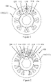
- FIGS. 1 and 2 a plurality of the radial magnetic bearing stator are illustrated.
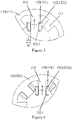
- FIGS. 3 and 4 illustrate the mounting process of the formed stator windings.
- Most of the arrangements of the radial magnetic bearing stators in these embodiments are similar. The difference mainly lies in the way the coil is connected between the windings when having different number of poles.
- the common characteristics of these embodiments of the winding method for radial magnetic bearing stator will be introduced first as follows, and then the unique characteristics thereof will be described with reference to different drawings.
- a radial magnetic bearing stator 100 shown in the figure comprises a stator core 110 formed by stacking a number of stator sheets.
- the stator core 110 has a stator yoke 111 and adjacent first stator teeth 112 and second stator teeth 113 disposed along the stator yoke 111, wherein a stator slot 114 is formed between the first stator teeth 112 and the second stator teeth 113.
- the winding method for radial magnetic bearing stator in this embodiment comprises at least two steps: firstly, S110 (as shown in FIG. 3 ) is performed, i.e., a first formed stator winding 120 with more coils is sleeved on the first stator tooth 112 of the stator core 110 along a radial outward direction. S120 is then performed (as shown in FIG.
- a second formed stator winding 130 with less coils to be connected in series with the first formed stator winding 120 is sleeved on the second stator tooth 113 of the stator core 110 along a radial outward direction.
- S130 is performed such that the first coil 121 of the first formed stator winding 120 is connected in series with the second coil 131 of the second formed stator winding 130.
- the number of coils that can be arranged in the stator slot can be increased as much as possible, thereby improving the slot space factor.
- the first formed stator winding 120 and the second formed stator winding 130 as a set with coils thereof connected in series, it can be ensured that for any set of stator windings that generate a magnetic field, they still have the same total coil numbers, so the magnetic field generated will not be offset due to the inconsistent coils of each winding.
- the work efficiency of the radial magnetic bearing is improved without increasing the stator size and maintaining the low cost as well.
- the method may further comprise step S100: winding the first coil 121 on a first wound bobbin 122 to form the first formed stator winding 120, and winding the second coil 131 on a second wound bobbin 132 to form the second formed stator winding 130.
- the first formed stator winding 120 thus formed comprises the first wound bobbin 122 and the first coil 121, and the first wound bobbin 122 has a first main body 1221 configured as a sleeve structure with a through hole.
- the through hole matches with the outer contour of the first stator tooth 112, such that the first main body 1221 is mounted on the first stator tooth 112 through the through hole.
- the first wound bobbin 122 also has first end stop walls 1222 disposed at both ends of the first main body 1221 to form a disc-shaped structure, and the middle portion thereof is kept open to avoid blocking of the through hole of the first main body 1221. With the help of the first end stop walls 1222, when the first coil 121 is wound on the first main body 1221 until it abuts against the first end stop walls 1222 on both sides, it will be limited by the first end stop walls 1222 along the radial direction.
- the second wound bobbin 132 has a second main body 1321 also configured as a sleeve structure with a through hole.
- the through hole matches with the outer contour of the second stator teeth 113, such that the second main body 1321 is mounted on the second stator teeth 113 through the through hole.
- the second wound bobbin 132 also has second end stop walls 1322 disposed at both ends of the second main body 1321 to form a disc-shaped structure, and the middle portion thereof is kept open to avoid blocking of the through hole of the second main body 1321.
- the first coil 121 can also be wound with respect to the first wound bobbin 122 to have a first thickness T, and the first thickness T may be approximately the width W in the opening direction of the stator slot 114 in the direction perpendicular to the slot wall of the stator slot 114.
- this step realizes that the first formed stator winding 120 mounted on the radial magnetic bearing stator has almost the largest possible coil number.
- the first coil 121 can also be wound with respect to the first wound bobbin 122 to have a varying thickness; wherein the first coil 121 with the varying thickness forms a tapered angle a at the radial inner end of the first wound bobbin 122, and the maximum thickness of the coil of the second formed stator winding 130 that can be sleeved on the second stator teeth 113 is limited between the tapered angle a thus formed and the second stator teeth 113.
- the number of coils of the second formed stator winding 130 that can possibly be mounted is also taken into consideration.
- the number of coils of the second formed stator winding 130 is adjusted by adjusting the contour enclosed by the first coil 121 wound with respect to the first wound bobbin 122 on the first formed stator winding 120, so that the second formed stator winding 130 can also have a relatively lager coil number, and the sum of the coil number of the two winding can be increased finally
- the winding method can be adjusted so that the tapered angle a formed by the first coil 121 is parallel to the side wall of the second stator tooth 113, that is, the angle a is substantially parallel and equal to the included angle of the opening of the stator slot (that is, the auxiliary dotted line of the tapered angle a shown in FIG. 3 is parallel to the left side wall of the second stator tooth 113; in other words, the tapered angle a shown in FIG. 3 is substantially the same as the included angle b of the left side wall of the second stator tooth 113 with respect to the first wound bobbin 122).
- the coil number of the second formed stator winding 130 can be further increased.
- stator 100 when the aforementioned winding method is applied to the eight-pole radial magnetic bearing stator 100, it is arranged such that a first formed stator winding 120 corresponds to a second formed stator winding 130, and the two are made to become a set of windings connected in series with each other. And at this time, two stator teeth are provided for mounting these windings, i.e., a first stator tooth 112 and a corresponding second stator teeth 113 adjacent to one side of the first stator tooth 112.
- FIG. 2 when the aforementioned winding method is applied to the twelve-pole radial magnetic bearing stator 100, it is arranged such that a first formed stator winding 120 corresponds to two second formed stator windings 130, and the three are made to become a set of windings connected in series with each other. And at this time, three stator teeth are provided for mounting these windings, i.e., a first stator tooth 112 and two corresponding second stator teeth 113 adjacent to both sides of the first stator tooth 112.
- a radial magnetic bearing according to the present application is further provided herein.
- the radial magnetic bearing comprises a radial magnetic bearing stator according to any of the foregoing embodiments or combinations thereof, and thus also has corresponding technical effects, which will not be repeated here.
Landscapes
- Engineering & Computer Science (AREA)
- General Engineering & Computer Science (AREA)
- Power Engineering (AREA)
- Mechanical Engineering (AREA)
- Manufacturing & Machinery (AREA)
- Magnetic Bearings And Hydrostatic Bearings (AREA)
- Manufacture Of Motors, Generators (AREA)
- Windings For Motors And Generators (AREA)
- Iron Core Of Rotating Electric Machines (AREA)
Abstract
Description
- The present invention relates to the field of manufacture of radial magnetic bearing parts, in particular to a winding method for radial magnetic bearing stator and a radial magnetic bearing stator and a radial magnetic bearing made using the same.
- As a mature power supply component, a radial magnetic bearing can receive electric power input, generate magnetic field and thereby output driving force, so as to provide suspension force for various types of rotating mechanical shafts. Among them, slot space factor is one of the indicators to measure its performance. Specifically, stator slot space factor refers to the ratio of the space occupied by the coils of the stator winding in the stator slot after it is placed in the stator slot. A higher slot space factor means that a stator of the same size is equipped with a stator winding with more coils, so it can also generate a stronger magnetic field at the same current. For the windings that are wound directly on the teeth of the stator, although the free winding process can be fully utilized to achieve a higher slot space factor, in practice, however, the requirements of the winding process is higher, and problems such as winding spread out or even fall off would readily occur. For the windings the winding process of which is completed in advance on wound bobbins or the like, they will be restricted by the opening width of the stator slot and the assembly process. The thickness of the winding shall not exceed the opening width of the stator slot, and it should also be ensured that the stator windings on the adjacent teeth sharing the stator slot can be mounted smoothly. As a result, the winding thickness is restricted in many ways, and the slot space factor is restricted accordingly.
- The present application aims to provide a winding method for radial magnetic bearing stator, a radial magnetic bearing stator and a radial magnetic bearing, so as to at least partially solve or alleviate the problems existing in the prior art.
- According to a first aspect a winding method for radial magnetic bearing stator is provided which comprises: S110, sleeving a first formed stator winding on a first stator tooth of a stator core along a radial outward direction; S120, sleeving a second formed stator winding on a second stator tooth of the stator core along a radial outward direction; S130, connecting a first coil of the first formed stator winding in series with a second coil of the second formed stator winding; wherein the first stator tooth is adjacent to the second stator tooth, and a stator slot is formed therebetween; and the coil number of the first formed stator winding is larger than that of the second formed stator winding.
- Optionally, before step S110, it further comprises: S100, winding the first coil on a first wound bobbin to form the first formed stator winding, and winding the second coil on a second wound bobbin to form the second formed stator winding; wherein the first wound bobbin and the second wound bobbin provide a radial limitation for the first coil and the second coil, respectively.
- Optionally, in step S100, the first coil is wound with respect to the first wound bobbin to have a first thickness, wherein the first thickness is approximately the width of the opening of the stator slot in the direction perpendicular to the slot wall of the stator slot.
- Optionally, in step S100, the first coil is wound with respect to the first wound bobbin to have a varying thickness; wherein the first coil with the varying thickness forms a tapered angle at the radial inner end of the first wound bobbin, and the maximum thickness of the coil of the second formed stator winding that can be sleeved on the second stator tooth is limited between the tapered angle and the second stator teeth.
- Optionally, the tapered angle formed by the first coil is parallel to the included angle of the opening of the stator slot.
- Optionally, when the radial magnetic bearing stator is an eight-pole stator, one of the first formed stator windings is corresponding to one of the second formed stator windings, and one of the first stator teeth is corresponding to one of the second stator teeth adjacent to one side of the first stator tooth; or, when the radial magnetic bearing stator is a twelve-pole stator, one of the first formed stator windings is corresponding to two of the second formed stator windings, and one of the first stator teeth is corresponding to two of the second stator teeth adjacent to both sides of the first stator tooth.
- According to another aspect a radial magnetic bearing stator is provided which comprises: a stator core having a stator yoke and adjacent first and second stator teeth disposed along the stator yoke, with a stator slot formed therebetween; a first formed stator winding sleeved on the first stator tooth of the stator core along a radial outward direction; and a second formed stator winding sleeved on the second stator tooth of the stator core along a radial outward direction; wherein a first coil of the first formed stator winding is connected in series with a second coil of the second formed stator winding; and the coil number of the first formed stator winding is larger than that of the second formed stator winding.
- Optionally, the first formed stator winding comprises: a first wound bobbin having a first main body and first end stop walls disposed at both ends of the first main body; the first coil is wound on the first wound bobbin, and is limited by the first end stop walls in the radial direction; and/or the second formed stator winding comprises: a second wound bobbin having a second main body and second end stop walls disposed at both ends of the second main body; the second coil is wound on the second wound bobbin, and is limited by the second end stop walls in the radial direction.
- Optionally, the maximum thickness of the first coil wound on the first wound bobbin is approximately the width of the opening of the stator slot in the direction perpendicular to the slot wall of the stator slot.
- Optionally, the first coil wound on the first wound bobbin forms a tapered angle at the inner radial end of the first wound bobbin, and the maximum thickness of the coil of the second formed stator winding that can be sleeved on the second stator tooth is limited between the tapered angle and the second stator tooth.
- Optionally, the tapered angle formed by the first coil is parallel to the included angle of the opening of the stator slot.
- Optionally, when the radial magnetic bearing stator is an eight-pole stator, one of the first formed stator windings corresponds to one of the second formed stator windings, and one of the first stator teeth corresponds to one of the second stator teeth adjacent to one side of the first stator tooth; or, when the radial magnetic bearing stator is a twelve-pole stator, one of the first formed stator windings corresponds to two of the second formed stator windings, and one of the first stator teeth corresponds to two of the second stator teeth adjacent to both sides of the first stator tooth.
- According to yet another aspect of the present application, a radial magnetic bearing is provided, which comprises the aforementioned radial magnetic bearing stator.
- According to the winding method for radial magnetic bearing stator and the radial magnetic bearing stator and the radial magnetic bearing made using the same of the present application, different formed stator windings the coil winding of which has been completed are successively sleeved on different stator teeth of the stator core, the first formed stator winding mounted in advance has more coils than the second formed stator winding, and the coils of the two are connected in series. As a result, for any set of stator windings that generate a magnetic field, they have the same total coil number, and can achieve a higher slot space factor, which improves the work efficiency of the radial magnetic bearing without increasing the stator size and maintaining the low cost as well.
- Certain exemplary embodiments will now be described in greater detail by way of example only and with reference to the accompanying drawings in which:
-
FIG. 1 is a schematic diagram of a radial magnetic bearing stator; -
FIG. 2 is a schematic diagram of a radial magnetic bearing stator; -
FIG. 3 is a schematic diagram of one step of a winding method for radial magnetic bearing stator; and -
FIG. 4 is a schematic diagram of another step of a winding method for radial magnetic bearing stator. - The present application will be described in detail below with reference to exemplary embodiments in the accompanying drawings. It should be appreciated, however, that the present application may be implemented in many different forms and shall not be construed as being limited to the embodiments set forth herein. These embodiments are provided herein so that the disclosure of the present application will become more thorough and complete, and the concept of the present application will be fully conveyed to those skilled in the art.
- In addition, for any single technical feature described or implied in the embodiments mentioned herein, or any single technical feature shown or implied in individual drawings, the present invention still allows for any combination or deletion of these technical features (or equivalents thereof) without any technical obstacle, thereby obtaining further embodiments of the present application that may not be directly mentioned herein.
- For the convenience of describing the embodiments mentioned herein, the axial direction, the radial direction and the circumferential direction are introduced herein as the reference coordinate system. The way of describing directions is used to express the structural characteristics of the respective components and the relative positional relationships therebetween, but not to restrict their absolute positional relationships. Taking the radial magnetic bearing stator in
FIG. 1 as an example, the axial direction means that a number of stator sheets of the radial magnetic bearing stator are stacked in the lamination direction of the stator core, the radial direction refers to the extension direction of the stator core radius, and the circumferential direction refers to the peripheral direction of the stator core. - Referring to
FIGS. 1 and 2 , a plurality of the radial magnetic bearing stator are illustrated.FIGS. 3 and 4 illustrate the mounting process of the formed stator windings. Most of the arrangements of the radial magnetic bearing stators in these embodiments are similar. The difference mainly lies in the way the coil is connected between the windings when having different number of poles. The common characteristics of these embodiments of the winding method for radial magnetic bearing stator will be introduced first as follows, and then the unique characteristics thereof will be described with reference to different drawings. - Referring first to
FIGS. 1 ,3 and 4 , in order to obtain the radial magnetic bearing stator shown inFIG. 1 , the steps shown inFIGS. 3 and 4 can be followed to assemble the formed stator windings. Specifically, a radialmagnetic bearing stator 100 shown in the figure comprises astator core 110 formed by stacking a number of stator sheets. Thestator core 110 has astator yoke 111 and adjacentfirst stator teeth 112 andsecond stator teeth 113 disposed along thestator yoke 111, wherein astator slot 114 is formed between thefirst stator teeth 112 and thesecond stator teeth 113. It should be appreciated that the aforementionedfirst stator teeth 112 and thesecond stator teeth 113 are for distinction and understanding when describing the solutions, but are not intended to limit the two to have different configurations. For example, in most cases, these stator teeth have the same shape and configuration for the purpose of simple molding and convenient processing. More specifically, the winding method for radial magnetic bearing stator in this embodiment comprises at least two steps: firstly, S110 (as shown inFIG. 3 ) is performed, i.e., a first formed stator winding 120 with more coils is sleeved on thefirst stator tooth 112 of thestator core 110 along a radial outward direction. S120 is then performed (as shown inFIG. 4 ), i.e., a second formed stator winding 130 with less coils to be connected in series with the first formed stator winding 120 is sleeved on thesecond stator tooth 113 of thestator core 110 along a radial outward direction. And then, S130 is performed such that thefirst coil 121 of the first formed stator winding 120 is connected in series with thesecond coil 131 of the second formed stator winding 130. - Under such an arrangement, by mounting the first formed stator winding 120 which has more coils than the second formed stator winding 130 in advance, the number of coils that can be arranged in the stator slot can be increased as much as possible, thereby improving the slot space factor. And, by arranging the first formed stator winding 120 and the second formed stator winding 130 as a set with coils thereof connected in series, it can be ensured that for any set of stator windings that generate a magnetic field, they still have the same total coil numbers, so the magnetic field generated will not be offset due to the inconsistent coils of each winding. Generally speaking, the work efficiency of the radial magnetic bearing is improved without increasing the stator size and maintaining the low cost as well.
- Further modifications on the winding method and the corresponding changes in the radial magnetic bearing stator structure will be introduced below by way of illustrative descriptions, so as to further improve the work efficiency and reliability thereof, or for other improvement considerations.
- For example, before performing the step of assembling the formed stator windings and the radial magnetic bearing stator, as an example of fabricating a formed stator winding, the method may further comprise step S100: winding the
first coil 121 on afirst wound bobbin 122 to form the first formed stator winding 120, and winding thesecond coil 131 on asecond wound bobbin 132 to form the second formed stator winding 130. The first formed stator winding 120 thus formed comprises thefirst wound bobbin 122 and thefirst coil 121, and thefirst wound bobbin 122 has a firstmain body 1221 configured as a sleeve structure with a through hole. The through hole matches with the outer contour of thefirst stator tooth 112, such that the firstmain body 1221 is mounted on thefirst stator tooth 112 through the through hole. Thefirst wound bobbin 122 also has firstend stop walls 1222 disposed at both ends of the firstmain body 1221 to form a disc-shaped structure, and the middle portion thereof is kept open to avoid blocking of the through hole of the firstmain body 1221. With the help of the firstend stop walls 1222, when thefirst coil 121 is wound on the firstmain body 1221 until it abuts against the firstend stop walls 1222 on both sides, it will be limited by the firstend stop walls 1222 along the radial direction. Similarly, thesecond wound bobbin 132 has a secondmain body 1321 also configured as a sleeve structure with a through hole. The through hole matches with the outer contour of thesecond stator teeth 113, such that the secondmain body 1321 is mounted on thesecond stator teeth 113 through the through hole. Thesecond wound bobbin 132 also has secondend stop walls 1322 disposed at both ends of the secondmain body 1321 to form a disc-shaped structure, and the middle portion thereof is kept open to avoid blocking of the through hole of the secondmain body 1321. With the help of the secondend stop walls 1322, when thesecond coil 131 is wound on the secondmain body 1321 until it abuts against the secondend stop walls 1322 on both sides, it will be limited by the secondend stop walls 1322 along the radial direction. As a result, the coils formed on the formed stator winding have a more reliable positioning, so problems such as extension deformation or fall off can be avoided. - On this basis, in order to further improve the slot space factor of the winding arrangement, in step S100, the
first coil 121 can also be wound with respect to thefirst wound bobbin 122 to have a first thickness T, and the first thickness T may be approximately the width W in the opening direction of thestator slot 114 in the direction perpendicular to the slot wall of thestator slot 114. At this time, considering the assembly tolerance and other issues, this step realizes that the first formed stator winding 120 mounted on the radial magnetic bearing stator has almost the largest possible coil number. - Similarly, also to further improve the slot space factor of the winding arrangement, in step S100, the
first coil 121 can also be wound with respect to thefirst wound bobbin 122 to have a varying thickness; wherein thefirst coil 121 with the varying thickness forms a tapered angle a at the radial inner end of thefirst wound bobbin 122, and the maximum thickness of the coil of the second formed stator winding 130 that can be sleeved on thesecond stator teeth 113 is limited between the tapered angle a thus formed and thesecond stator teeth 113. At this time, when the first formed stator winding 120 is mounted, the number of coils of the second formed stator winding 130 that can possibly be mounted is also taken into consideration. And, the number of coils of the second formed stator winding 130 is adjusted by adjusting the contour enclosed by thefirst coil 121 wound with respect to thefirst wound bobbin 122 on the first formed stator winding 120, so that the second formed stator winding 130 can also have a relatively lager coil number, and the sum of the coil number of the two winding can be increased finally - On this basis, optionally, the winding method can be adjusted so that the tapered angle a formed by the
first coil 121 is parallel to the side wall of thesecond stator tooth 113, that is, the angle a is substantially parallel and equal to the included angle of the opening of the stator slot (that is, the auxiliary dotted line of the tapered angle a shown inFIG. 3 is parallel to the left side wall of thesecond stator tooth 113; in other words, the tapered angle a shown inFIG. 3 is substantially the same as the included angle b of the left side wall of thesecond stator tooth 113 with respect to the first wound bobbin 122). At this time, the coil number of the second formed stator winding 130 can be further increased. - With continued reference to
FIG. 1 , when the aforementioned winding method is applied to the eight-pole radialmagnetic bearing stator 100, it is arranged such that a first formed stator winding 120 corresponds to a second formed stator winding 130, and the two are made to become a set of windings connected in series with each other. And at this time, two stator teeth are provided for mounting these windings, i.e., afirst stator tooth 112 and a correspondingsecond stator teeth 113 adjacent to one side of thefirst stator tooth 112. - Turning to
FIG. 2 , when the aforementioned winding method is applied to the twelve-pole radialmagnetic bearing stator 100, it is arranged such that a first formed stator winding 120 corresponds to two second formedstator windings 130, and the three are made to become a set of windings connected in series with each other. And at this time, three stator teeth are provided for mounting these windings, i.e., afirst stator tooth 112 and two correspondingsecond stator teeth 113 adjacent to both sides of thefirst stator tooth 112. - In addition, although not shown in the figures, an embodiment of a radial magnetic bearing according to the present application is further provided herein. The radial magnetic bearing comprises a radial magnetic bearing stator according to any of the foregoing embodiments or combinations thereof, and thus also has corresponding technical effects, which will not be repeated here.
- The above examples mainly describe a winding method for radial magnetic bearing stator, a radial magnetic bearing stator and a radial magnetic bearing. Although only a few of the embodiments are described, those skilled in the art shall appreciate that the present invention may, without departing from the scope thereof, be implemented in many other forms. Accordingly, the examples and embodiments illustrated are to be regarded as illustrative but not restrictive, and the present invention may, without departing from the scope of the appended claims, cover various modifications and replacements.
Claims (13)
- A winding method for radial magnetic bearing stator (100), comprising:S110, sleeving a first formed stator winding (120) on a first stator tooth (112) of a stator core (110) along a radial outward direction;S120, sleeving a second formed stator winding (130) on a second stator tooth (113) of the stator core (110) along a radial outward direction;S130, a first coil (121) of the first formed stator winding (120) is connected in series with a second coil (131) of the second formed stator winding (130);wherein the first stator tooth (112) is adjacent to the second stator tooth (113), and a stator slot (114) is formed therebetween; and the coil number of the first formed stator winding (120) is larger than that of the second formed stator winding (130).
- The winding method according to claim 1, wherein before step S110, further comprising: S100, winding the first coil (121) on a first wound bobbin (122) to form the first formed stator winding (120), and winding the second coil (131) on a second wound bobbin (132) to form the second formed stator winding (130); wherein the first wound bobbin (122) and the second wound bobbin (132) provide a radial limitation for the first coil (121) and the second coil (131), respectively.
- The winding method according to claim 2, wherein in step S100, the first coil (121) is wound with respect to the first wound bobbin (122) to have a first thickness, and the first thickness is approximately a width of an opening of the stator slot (114) in a direction perpendicular to a slot wall of the stator slot (114).
- The winding method according to claim 2, wherein in step S100, the first coil (121) is wound with respect to the first wound bobbin (122) to have a varying thickness; wherein the first coil (121) having the varying thickness forms a tapered angle at the radial inner end of the first wound bobbin (122), and a maximum thickness of the coil of the second formed stator winding (130) that can be sleeved on the second stator tooth (113) is limited between the tapered angle and the second stator tooth (113).
- The winding method according to claim 4, wherein the tapered angle formed by the first coil (121) is parallel to an included angle of the opening of the stator slot (114).
- The winding method according to any preceding claim, wherein when the radial magnetic bearing stator (100) is an eight-pole stator, one of the first formed stator windings (120) is corresponding to one of the second formed stator windings (130), and one of the first stator teeth (112) is corresponding to one of the second stator teeth (113) adjacent to one side of the first stator tooth (112); or, when the radial magnetic bearing stator (100) is a twelve-pole stator, one of the first formed stator windings (120) is corresponding to two of the second formed stator windings (130), and one of the first stator teeth (112) is corresponding to two of the second stator teeth (113) adjacent to both sides of the first stator tooth (112).
- A radial magnetic bearing stator (100), comprising:a stator core (110) having a stator yoke (111) and adjacent first and second stator teeth (112, 113) disposed along the stator yoke (111), with a stator slot (114) formed therebetween;a first formed stator winding (120) sleeved on the first stator tooth (112) of the stator core (110) along a radial outward direction; anda second formed stator winding (130) sleeved on a second stator tooth (113) of the stator core (110) along a radial outward direction;wherein, a first coil (121) of the first formed stator winding (120) is connected in series with a second coil (131) of the second formed stator winding (130); and the coil number of the first formed stator winding (120) is larger than that of the second formed stator winding (130).
- The radial magnetic bearing stator (100) according to claim 7, wherein,the first formed stator winding (120) comprises:a first wound bobbin (122) having a first main body (1221) and first end stop walls (1222) disposed at both ends of the first main body (1221);wherein the first coil (121) is wound on the first wound bobbin (122) and is limited by the first end stop walls (1222) in the radial direction; and/orthe second formed stator winding (130) comprises:a second wound bobbin (132) having a second main body (1321) and second end stop walls (1322) disposed at both ends of the second main body (1321);wherein the second coil (131) is wound on the second wound bobbin (132) and is limited by the second end stop walls (1322) in the radial direction.
- The radial magnetic bearing stator (100) according to claim 8, wherein a maximum thickness of the first coil (121) wound on the first wound bobbin (122) is approximately a width of an opening of the stator slot (114) in a direction perpendicular to a slot wall of the stator slot (114).
- The radial magnetic bearing stator (100) according to claim 8 or 9, wherein the first coil (121) wound on the first wound bobbin (122) forms a tapered angle at the radial inner end of the first wound bobbin (122), and a maximum thickness of the coil of the second formed stator winding (130) that can be sleeved on the second stator tooth (113) is limited between the tapered angle and the second stator tooth (113).
- The radial magnetic bearing stator (100) according to claim 10, wherein the tapered angle formed by the first coil (121) is parallel to an included angle of the opening of the stator slot (114).
- The radial magnetic bearing stator (100) according to any of claims 7 to 11, wherein when the radial magnetic bearing stator (100) is an eight-pole stator, one of the first formed stator windings (120) corresponds to one of the second formed stator windings (130), and one of the first stator teeth corresponds to one of the second stator teeth (113) adjacent to one side of the first stator tooth (112); or, when the radial magnetic bearing stator (100) is a twelve-pole stator, one of the first formed stator windings (120) corresponds to two of the second formed stator windings (130), and one of the first stator teeth (112) corresponds to two of the second stator teeth (113) adjacent to both sides of the first stator tooth (112).
- A radial magnetic bearing, comprising: the radial magnetic bearing stator (100) according to any of claims 7 to 12.
Applications Claiming Priority (1)
| Application Number | Priority Date | Filing Date | Title |
|---|---|---|---|
| CN202110558085.5A CN115370661A (en) | 2021-05-21 | 2021-05-21 | Winding method of radial magnetic bearing stator, radial magnetic bearing stator and radial magnetic bearing |
Publications (2)
| Publication Number | Publication Date |
|---|---|
| EP4092283A1 true EP4092283A1 (en) | 2022-11-23 |
| EP4092283B1 EP4092283B1 (en) | 2024-03-13 |
Family
ID=81749296
Family Applications (1)
| Application Number | Title | Priority Date | Filing Date |
|---|---|---|---|
| EP22174432.9A Active EP4092283B1 (en) | 2021-05-21 | 2022-05-19 | Winding method for radial magnetic bearing stator, radial magnetic bearing stator and radial magnetic bearing |
Country Status (4)
| Country | Link |
|---|---|
| US (1) | US12297865B2 (en) |
| EP (1) | EP4092283B1 (en) |
| CN (1) | CN115370661A (en) |
| ES (1) | ES2975666T3 (en) |
Citations (4)
| Publication number | Priority date | Publication date | Assignee | Title |
|---|---|---|---|---|
| US20050077793A1 (en) * | 2001-10-05 | 2005-04-14 | Seamus Garvey | Electrical machine having capability to generate lateral forces |
| DE202007007579U1 (en) * | 2007-03-16 | 2007-08-09 | Egston System Electronics Eggenburg Gmbh | Coil with a machine layer winding |
| EP2779373A2 (en) * | 2013-03-15 | 2014-09-17 | Ingersoll-Rand Company | Rotating machine with magnetic bearing |
| EP2896842A1 (en) * | 2012-09-12 | 2015-07-22 | Daikin Industries, Ltd. | Magnetic bearing |
Family Cites Families (37)
| Publication number | Priority date | Publication date | Assignee | Title |
|---|---|---|---|---|
| US4100444A (en) | 1975-09-29 | 1978-07-11 | General Electric Company | Dynamoelectric machine winding arrangement |
| DE19704652C1 (en) | 1997-02-07 | 1998-07-30 | Anton Knestel | Use of a ring winding in electrical induction machines |
| CN1168189C (en) | 2001-02-13 | 2004-09-22 | 许俊甫 | Combined Stator Structure |
| JP3952290B2 (en) * | 2002-09-06 | 2007-08-01 | ヤマハモーターエレクトロニクス株式会社 | Armature of rotating electrical equipment and winding method thereof |
| JP2005073450A (en) | 2003-08-27 | 2005-03-17 | Matsushita Electric Ind Co Ltd | Motor generator |
| US20050258702A1 (en) | 2004-05-19 | 2005-11-24 | Michaels Paul G | Multiple winding coil shapes for increased slot fill |
| JP3672919B1 (en) | 2004-08-17 | 2005-07-20 | 山洋電気株式会社 | Permanent magnet type rotary motor |
| GB0609045D0 (en) | 2006-05-06 | 2006-06-14 | Trw Ltd | Electric motor windings |
| DE102006021354A1 (en) | 2006-05-08 | 2007-11-15 | Siemens Ag | Electric machine, in particular synchronous motor, with redundant stator windings |
| EP2104202A1 (en) | 2008-03-18 | 2009-09-23 | Phase Motion Control S.r.l. | Electric Motor with permanent magnet rotor |
| GR1007565B (en) * | 2010-09-08 | 2012-03-26 | ΠΑΝΕΠΙΣΤΗΜΙΟ ΠΑΤΡΩΝ (κατά ποσοστό 40%), | Hybrid sliding-contact bearing |
| US8704422B2 (en) | 2010-11-18 | 2014-04-22 | Nidec Motor Corporation | Full round stator assembly and electromagnetic machine having high slot fill |
| CN106887915B (en) | 2011-02-14 | 2019-02-05 | 三菱电机株式会社 | The stator of rotating electric machine |
| KR20130109650A (en) | 2012-03-28 | 2013-10-08 | 삼성전기주식회사 | Stator core assembly and spindle motor having the same |
| JP5944984B2 (en) | 2012-04-18 | 2016-07-05 | 三菱電機株式会社 | Stator manufacturing method |
| CN203086252U (en) | 2012-12-31 | 2013-07-24 | 上海御能动力科技有限公司 | Servo motor stator employing closed slot and modular concentrated winding |
| CN103973057A (en) | 2013-01-25 | 2014-08-06 | 广东美的环境电器制造有限公司 | Segmented stator, manufacturing method thereof, motor and household appliance having same |
| DE102013201861B3 (en) | 2013-02-05 | 2014-07-17 | Siemens Aktiengesellschaft | Pole element for axial shaft rotatable rotor for electrically-excited synchronous generator, has pole unit whose aspect ratio between axial length of pole unit and pole component are provided as function of flux ratio |
| CN104600880A (en) | 2013-10-30 | 2015-05-06 | 河南超微电动汽车有限公司 | Stator-split alternating-current servo motor |
| CN103647421A (en) | 2013-11-20 | 2014-03-19 | 江苏大学 | High slot-fill factor high-performance permanent magnet motor with open slots and straight teeth |
| CN203660676U (en) | 2014-01-06 | 2014-06-18 | 常州雷利电机科技有限公司 | Stator core for brushless motor |
| US20160036277A1 (en) | 2014-08-04 | 2016-02-04 | Hamilton Sundstrand Corporation | Strand cross-section for high fill-factor electric machine windings |
| US20160372984A1 (en) * | 2015-06-19 | 2016-12-22 | Bose Corporation | Stator |
| CN105515230B (en) | 2015-12-31 | 2019-04-23 | 北京金风科创风电设备有限公司 | stator of generator |
| CN107134867B (en) | 2016-02-29 | 2024-06-14 | 中石化石油工程技术服务有限公司 | Extra-long core and few-coil permanent magnet synchronous motor for driving underground electric drilling tools |
| US10784736B2 (en) | 2016-07-28 | 2020-09-22 | Borgwarner Inc. | Electric machine with stator having even slot distribution |
| CN107026528B (en) | 2017-05-31 | 2024-01-05 | 广东美芝制冷设备有限公司 | Compressor motor and its stator |
| US10693336B2 (en) | 2017-06-02 | 2020-06-23 | Whirlpool Corporation | Winding configuration electric motor |
| CN109802500A (en) | 2017-11-16 | 2019-05-24 | 深圳东明机电股份有限公司 | Motor stator component and stator core |
| CN108377042B (en) | 2018-04-15 | 2019-06-07 | 佛山市顺德区致翔金属制品有限公司 | Pole piece spacing coiling combined-stator |
| CN108377043B (en) | 2018-04-15 | 2019-11-08 | 平湖市超凯科技有限公司 | Pole piece spacing permutation and combination type stator |
| CN108377044B (en) | 2018-04-24 | 2019-04-30 | 盐城杰精机械制造有限公司 | Pole-changing arc length phase shift starts motor stator |
| CN108768006B (en) | 2018-08-17 | 2019-08-27 | 无锡晶晟科技股份有限公司 | Stator laminating structure of motor and its method for winding |
| CN109193992B (en) | 2018-11-26 | 2020-12-01 | 山东理工大学 | Modular motor with pre-wound high-slot full-rate windings for electric vehicles |
| CN109818444A (en) | 2019-02-18 | 2019-05-28 | 浙江龙芯电驱动科技有限公司 | A kind of high copper factor concentratred winding brushless motor stator |
| CN209767266U (en) | 2019-02-18 | 2019-12-10 | 浙江龙芯电驱动科技有限公司 | High-slot-filling-rate concentrated winding brushless motor stator |
| CN109672277B (en) | 2019-02-26 | 2024-05-31 | 苏州新智机电工业有限公司 | Motor stator of electric compressor and manufacturing method thereof |
-
2021
- 2021-05-21 CN CN202110558085.5A patent/CN115370661A/en active Pending
-
2022
- 2022-05-18 US US17/747,578 patent/US12297865B2/en active Active
- 2022-05-19 EP EP22174432.9A patent/EP4092283B1/en active Active
- 2022-05-19 ES ES22174432T patent/ES2975666T3/en active Active
Patent Citations (4)
| Publication number | Priority date | Publication date | Assignee | Title |
|---|---|---|---|---|
| US20050077793A1 (en) * | 2001-10-05 | 2005-04-14 | Seamus Garvey | Electrical machine having capability to generate lateral forces |
| DE202007007579U1 (en) * | 2007-03-16 | 2007-08-09 | Egston System Electronics Eggenburg Gmbh | Coil with a machine layer winding |
| EP2896842A1 (en) * | 2012-09-12 | 2015-07-22 | Daikin Industries, Ltd. | Magnetic bearing |
| EP2779373A2 (en) * | 2013-03-15 | 2014-09-17 | Ingersoll-Rand Company | Rotating machine with magnetic bearing |
Also Published As
| Publication number | Publication date |
|---|---|
| CN115370661A (en) | 2022-11-22 |
| ES2975666T3 (en) | 2024-07-11 |
| US20220373026A1 (en) | 2022-11-24 |
| US12297865B2 (en) | 2025-05-13 |
| EP4092283B1 (en) | 2024-03-13 |
Similar Documents
| Publication | Publication Date | Title |
|---|---|---|
| US11355975B2 (en) | Stator for motor and method of manufacturing | |
| US12244176B2 (en) | Stator of an electric machine | |
| US7915780B2 (en) | Laminated spiral core, dynamo-electric-machine rotor provided therewith, and dynamo-electric machine | |
| JP2014014231A (en) | Electric motor | |
| US20180351417A1 (en) | Rotating electric machine stator, rotating electric machine, and method for manufacturing rotating electric machine stator | |
| US20130342065A1 (en) | Brushless motor and method for manufacturing brushless motor | |
| CN117879197B (en) | Stator cores, stator assemblies, linear motors, suspension systems and vehicles | |
| JPWO2018037529A1 (en) | Rotating electric machine | |
| US20070267932A1 (en) | Stator for inner rotor type rotating electric machine | |
| JPH10304608A (en) | Electric motor | |
| US7692351B2 (en) | Winding structure of rotating electric machine | |
| JP3056738B1 (en) | Manufacturing method of condenser motor stator | |
| JP2019221113A (en) | Stator and rotary electric machine | |
| US20180054149A1 (en) | Synchronous motor having component identical to that of another kind of synchronous motor and method of manufacturing synchronous motors | |
| US20190131840A1 (en) | Rotary Electric Machine | |
| CN116418183A (en) | Stator core manufacturing method and outer rotor motor | |
| EP4092283B1 (en) | Winding method for radial magnetic bearing stator, radial magnetic bearing stator and radial magnetic bearing | |
| US20040000837A1 (en) | Electric rotary machine | |
| JP2022011327A (en) | Permanent magnet rotary electric machine and rotor | |
| CN111181265A (en) | Distributed winding motor without inner slots and assembly method thereof | |
| EP4044402B1 (en) | Motor | |
| JP4548381B2 (en) | Insulator, rotating electric machine, manufacturing method thereof, and electric vehicle | |
| JP2012235572A (en) | Capacitor motor | |
| CN221552913U (en) | Electric excitation synchronous motor, transmission system and vehicle | |
| CN223487937U (en) | Stator core, stator, brushless motor, end effector and robot |
Legal Events
| Date | Code | Title | Description |
|---|---|---|---|
| PUAI | Public reference made under article 153(3) epc to a published international application that has entered the european phase |
Free format text: ORIGINAL CODE: 0009012 |
|
| STAA | Information on the status of an ep patent application or granted ep patent |
Free format text: STATUS: THE APPLICATION HAS BEEN PUBLISHED |
|
| AK | Designated contracting states |
Kind code of ref document: A1 Designated state(s): AL AT BE BG CH CY CZ DE DK EE ES FI FR GB GR HR HU IE IS IT LI LT LU LV MC MK MT NL NO PL PT RO RS SE SI SK SM TR |
|
| STAA | Information on the status of an ep patent application or granted ep patent |
Free format text: STATUS: REQUEST FOR EXAMINATION WAS MADE |
|
| 17P | Request for examination filed |
Effective date: 20230519 |
|
| RBV | Designated contracting states (corrected) |
Designated state(s): AL AT BE BG CH CY CZ DE DK EE ES FI FR GB GR HR HU IE IS IT LI LT LU LV MC MK MT NL NO PL PT RO RS SE SI SK SM TR |
|
| P01 | Opt-out of the competence of the unified patent court (upc) registered |
Effective date: 20230527 |
|
| GRAP | Despatch of communication of intention to grant a patent |
Free format text: ORIGINAL CODE: EPIDOSNIGR1 |
|
| STAA | Information on the status of an ep patent application or granted ep patent |
Free format text: STATUS: GRANT OF PATENT IS INTENDED |
|
| INTG | Intention to grant announced |
Effective date: 20231002 |
|
| GRAS | Grant fee paid |
Free format text: ORIGINAL CODE: EPIDOSNIGR3 |
|
| GRAA | (expected) grant |
Free format text: ORIGINAL CODE: 0009210 |
|
| STAA | Information on the status of an ep patent application or granted ep patent |
Free format text: STATUS: THE PATENT HAS BEEN GRANTED |
|
| AK | Designated contracting states |
Kind code of ref document: B1 Designated state(s): AL AT BE BG CH CY CZ DE DK EE ES FI FR GB GR HR HU IE IS IT LI LT LU LV MC MK MT NL NO PL PT RO RS SE SI SK SM TR |
|
| REG | Reference to a national code |
Ref country code: GB Ref legal event code: FG4D |
|
| REG | Reference to a national code |
Ref country code: CH Ref legal event code: EP |
|
| REG | Reference to a national code |
Ref country code: NL Ref legal event code: FP |
|
| REG | Reference to a national code |
Ref country code: DE Ref legal event code: R096 Ref document number: 602022002324 Country of ref document: DE |
|
| REG | Reference to a national code |
Ref country code: IE Ref legal event code: FG4D |
|
| PG25 | Lapsed in a contracting state [announced via postgrant information from national office to epo] |
Ref country code: LT Free format text: LAPSE BECAUSE OF FAILURE TO SUBMIT A TRANSLATION OF THE DESCRIPTION OR TO PAY THE FEE WITHIN THE PRESCRIBED TIME-LIMIT Effective date: 20240313 |
|
| REG | Reference to a national code |
Ref country code: LT Ref legal event code: MG9D |
|
| REG | Reference to a national code |
Ref country code: ES Ref legal event code: FG2A Ref document number: 2975666 Country of ref document: ES Kind code of ref document: T3 Effective date: 20240711 |
|
| PG25 | Lapsed in a contracting state [announced via postgrant information from national office to epo] |
Ref country code: GR Free format text: LAPSE BECAUSE OF FAILURE TO SUBMIT A TRANSLATION OF THE DESCRIPTION OR TO PAY THE FEE WITHIN THE PRESCRIBED TIME-LIMIT Effective date: 20240614 |
|
| PG25 | Lapsed in a contracting state [announced via postgrant information from national office to epo] |
Ref country code: HR Free format text: LAPSE BECAUSE OF FAILURE TO SUBMIT A TRANSLATION OF THE DESCRIPTION OR TO PAY THE FEE WITHIN THE PRESCRIBED TIME-LIMIT Effective date: 20240313 Ref country code: RS Free format text: LAPSE BECAUSE OF FAILURE TO SUBMIT A TRANSLATION OF THE DESCRIPTION OR TO PAY THE FEE WITHIN THE PRESCRIBED TIME-LIMIT Effective date: 20240613 |
|
| PGFP | Annual fee paid to national office [announced via postgrant information from national office to epo] |
Ref country code: ES Payment date: 20240603 Year of fee payment: 3 |
|
| PG25 | Lapsed in a contracting state [announced via postgrant information from national office to epo] |
Ref country code: RS Free format text: LAPSE BECAUSE OF FAILURE TO SUBMIT A TRANSLATION OF THE DESCRIPTION OR TO PAY THE FEE WITHIN THE PRESCRIBED TIME-LIMIT Effective date: 20240613 Ref country code: NO Free format text: LAPSE BECAUSE OF FAILURE TO SUBMIT A TRANSLATION OF THE DESCRIPTION OR TO PAY THE FEE WITHIN THE PRESCRIBED TIME-LIMIT Effective date: 20240613 Ref country code: LT Free format text: LAPSE BECAUSE OF FAILURE TO SUBMIT A TRANSLATION OF THE DESCRIPTION OR TO PAY THE FEE WITHIN THE PRESCRIBED TIME-LIMIT Effective date: 20240313 Ref country code: HR Free format text: LAPSE BECAUSE OF FAILURE TO SUBMIT A TRANSLATION OF THE DESCRIPTION OR TO PAY THE FEE WITHIN THE PRESCRIBED TIME-LIMIT Effective date: 20240313 Ref country code: GR Free format text: LAPSE BECAUSE OF FAILURE TO SUBMIT A TRANSLATION OF THE DESCRIPTION OR TO PAY THE FEE WITHIN THE PRESCRIBED TIME-LIMIT Effective date: 20240614 Ref country code: FI Free format text: LAPSE BECAUSE OF FAILURE TO SUBMIT A TRANSLATION OF THE DESCRIPTION OR TO PAY THE FEE WITHIN THE PRESCRIBED TIME-LIMIT Effective date: 20240313 Ref country code: BG Free format text: LAPSE BECAUSE OF FAILURE TO SUBMIT A TRANSLATION OF THE DESCRIPTION OR TO PAY THE FEE WITHIN THE PRESCRIBED TIME-LIMIT Effective date: 20240313 |
|
| REG | Reference to a national code |
Ref country code: AT Ref legal event code: MK05 Ref document number: 1666012 Country of ref document: AT Kind code of ref document: T Effective date: 20240313 |
|
| PG25 | Lapsed in a contracting state [announced via postgrant information from national office to epo] |
Ref country code: SE Free format text: LAPSE BECAUSE OF FAILURE TO SUBMIT A TRANSLATION OF THE DESCRIPTION OR TO PAY THE FEE WITHIN THE PRESCRIBED TIME-LIMIT Effective date: 20240313 Ref country code: LV Free format text: LAPSE BECAUSE OF FAILURE TO SUBMIT A TRANSLATION OF THE DESCRIPTION OR TO PAY THE FEE WITHIN THE PRESCRIBED TIME-LIMIT Effective date: 20240313 |
|
| PGFP | Annual fee paid to national office [announced via postgrant information from national office to epo] |
Ref country code: BE Payment date: 20240418 Year of fee payment: 3 |
|
| PG25 | Lapsed in a contracting state [announced via postgrant information from national office to epo] |
Ref country code: IS Free format text: LAPSE BECAUSE OF FAILURE TO SUBMIT A TRANSLATION OF THE DESCRIPTION OR TO PAY THE FEE WITHIN THE PRESCRIBED TIME-LIMIT Effective date: 20240713 |
|
| PG25 | Lapsed in a contracting state [announced via postgrant information from national office to epo] |
Ref country code: SM Free format text: LAPSE BECAUSE OF FAILURE TO SUBMIT A TRANSLATION OF THE DESCRIPTION OR TO PAY THE FEE WITHIN THE PRESCRIBED TIME-LIMIT Effective date: 20240313 Ref country code: PT Free format text: LAPSE BECAUSE OF FAILURE TO SUBMIT A TRANSLATION OF THE DESCRIPTION OR TO PAY THE FEE WITHIN THE PRESCRIBED TIME-LIMIT Effective date: 20240715 |
|
| PG25 | Lapsed in a contracting state [announced via postgrant information from national office to epo] |
Ref country code: EE Free format text: LAPSE BECAUSE OF FAILURE TO SUBMIT A TRANSLATION OF THE DESCRIPTION OR TO PAY THE FEE WITHIN THE PRESCRIBED TIME-LIMIT Effective date: 20240313 Ref country code: CZ Free format text: LAPSE BECAUSE OF FAILURE TO SUBMIT A TRANSLATION OF THE DESCRIPTION OR TO PAY THE FEE WITHIN THE PRESCRIBED TIME-LIMIT Effective date: 20240313 |
|
| PG25 | Lapsed in a contracting state [announced via postgrant information from national office to epo] |
Ref country code: AT Free format text: LAPSE BECAUSE OF FAILURE TO SUBMIT A TRANSLATION OF THE DESCRIPTION OR TO PAY THE FEE WITHIN THE PRESCRIBED TIME-LIMIT Effective date: 20240313 |
|
| PG25 | Lapsed in a contracting state [announced via postgrant information from national office to epo] |
Ref country code: PL Free format text: LAPSE BECAUSE OF FAILURE TO SUBMIT A TRANSLATION OF THE DESCRIPTION OR TO PAY THE FEE WITHIN THE PRESCRIBED TIME-LIMIT Effective date: 20240313 |
|
| PG25 | Lapsed in a contracting state [announced via postgrant information from national office to epo] |
Ref country code: SK Free format text: LAPSE BECAUSE OF FAILURE TO SUBMIT A TRANSLATION OF THE DESCRIPTION OR TO PAY THE FEE WITHIN THE PRESCRIBED TIME-LIMIT Effective date: 20240313 |
|
| PG25 | Lapsed in a contracting state [announced via postgrant information from national office to epo] |
Ref country code: SM Free format text: LAPSE BECAUSE OF FAILURE TO SUBMIT A TRANSLATION OF THE DESCRIPTION OR TO PAY THE FEE WITHIN THE PRESCRIBED TIME-LIMIT Effective date: 20240313 Ref country code: SK Free format text: LAPSE BECAUSE OF FAILURE TO SUBMIT A TRANSLATION OF THE DESCRIPTION OR TO PAY THE FEE WITHIN THE PRESCRIBED TIME-LIMIT Effective date: 20240313 Ref country code: RO Free format text: LAPSE BECAUSE OF FAILURE TO SUBMIT A TRANSLATION OF THE DESCRIPTION OR TO PAY THE FEE WITHIN THE PRESCRIBED TIME-LIMIT Effective date: 20240313 Ref country code: PT Free format text: LAPSE BECAUSE OF FAILURE TO SUBMIT A TRANSLATION OF THE DESCRIPTION OR TO PAY THE FEE WITHIN THE PRESCRIBED TIME-LIMIT Effective date: 20240715 Ref country code: PL Free format text: LAPSE BECAUSE OF FAILURE TO SUBMIT A TRANSLATION OF THE DESCRIPTION OR TO PAY THE FEE WITHIN THE PRESCRIBED TIME-LIMIT Effective date: 20240313 Ref country code: IS Free format text: LAPSE BECAUSE OF FAILURE TO SUBMIT A TRANSLATION OF THE DESCRIPTION OR TO PAY THE FEE WITHIN THE PRESCRIBED TIME-LIMIT Effective date: 20240713 Ref country code: EE Free format text: LAPSE BECAUSE OF FAILURE TO SUBMIT A TRANSLATION OF THE DESCRIPTION OR TO PAY THE FEE WITHIN THE PRESCRIBED TIME-LIMIT Effective date: 20240313 Ref country code: CZ Free format text: LAPSE BECAUSE OF FAILURE TO SUBMIT A TRANSLATION OF THE DESCRIPTION OR TO PAY THE FEE WITHIN THE PRESCRIBED TIME-LIMIT Effective date: 20240313 Ref country code: AT Free format text: LAPSE BECAUSE OF FAILURE TO SUBMIT A TRANSLATION OF THE DESCRIPTION OR TO PAY THE FEE WITHIN THE PRESCRIBED TIME-LIMIT Effective date: 20240313 |
|
| REG | Reference to a national code |
Ref country code: DE Ref legal event code: R097 Ref document number: 602022002324 Country of ref document: DE |
|
| PG25 | Lapsed in a contracting state [announced via postgrant information from national office to epo] |
Ref country code: MC Free format text: LAPSE BECAUSE OF FAILURE TO SUBMIT A TRANSLATION OF THE DESCRIPTION OR TO PAY THE FEE WITHIN THE PRESCRIBED TIME-LIMIT Effective date: 20240313 |
|
| PG25 | Lapsed in a contracting state [announced via postgrant information from national office to epo] |
Ref country code: DK Free format text: LAPSE BECAUSE OF FAILURE TO SUBMIT A TRANSLATION OF THE DESCRIPTION OR TO PAY THE FEE WITHIN THE PRESCRIBED TIME-LIMIT Effective date: 20240313 |
|
| PG25 | Lapsed in a contracting state [announced via postgrant information from national office to epo] |
Ref country code: LU Free format text: LAPSE BECAUSE OF NON-PAYMENT OF DUE FEES Effective date: 20240519 |
|
| PLBE | No opposition filed within time limit |
Free format text: ORIGINAL CODE: 0009261 |
|
| STAA | Information on the status of an ep patent application or granted ep patent |
Free format text: STATUS: NO OPPOSITION FILED WITHIN TIME LIMIT |
|
| PG25 | Lapsed in a contracting state [announced via postgrant information from national office to epo] |
Ref country code: MC Free format text: LAPSE BECAUSE OF FAILURE TO SUBMIT A TRANSLATION OF THE DESCRIPTION OR TO PAY THE FEE WITHIN THE PRESCRIBED TIME-LIMIT Effective date: 20240313 Ref country code: LU Free format text: LAPSE BECAUSE OF NON-PAYMENT OF DUE FEES Effective date: 20240519 Ref country code: DK Free format text: LAPSE BECAUSE OF FAILURE TO SUBMIT A TRANSLATION OF THE DESCRIPTION OR TO PAY THE FEE WITHIN THE PRESCRIBED TIME-LIMIT Effective date: 20240313 |
|
| 26N | No opposition filed |
Effective date: 20241216 |
|
| PG25 | Lapsed in a contracting state [announced via postgrant information from national office to epo] |
Ref country code: IE Free format text: LAPSE BECAUSE OF NON-PAYMENT OF DUE FEES Effective date: 20240519 |
|
| PG25 | Lapsed in a contracting state [announced via postgrant information from national office to epo] |
Ref country code: SI Free format text: LAPSE BECAUSE OF FAILURE TO SUBMIT A TRANSLATION OF THE DESCRIPTION OR TO PAY THE FEE WITHIN THE PRESCRIBED TIME-LIMIT Effective date: 20240313 |
|
| PGFP | Annual fee paid to national office [announced via postgrant information from national office to epo] |
Ref country code: DE Payment date: 20250423 Year of fee payment: 4 |
|
| PGFP | Annual fee paid to national office [announced via postgrant information from national office to epo] |
Ref country code: IT Payment date: 20250531 Year of fee payment: 4 |
|
| PGFP | Annual fee paid to national office [announced via postgrant information from national office to epo] |
Ref country code: FR Payment date: 20250423 Year of fee payment: 4 |
|
| PG25 | Lapsed in a contracting state [announced via postgrant information from national office to epo] |
Ref country code: CY Free format text: LAPSE BECAUSE OF FAILURE TO SUBMIT A TRANSLATION OF THE DESCRIPTION OR TO PAY THE FEE WITHIN THE PRESCRIBED TIME-LIMIT; INVALID AB INITIO Effective date: 20220519 |
|
| PG25 | Lapsed in a contracting state [announced via postgrant information from national office to epo] |
Ref country code: HU Free format text: LAPSE BECAUSE OF FAILURE TO SUBMIT A TRANSLATION OF THE DESCRIPTION OR TO PAY THE FEE WITHIN THE PRESCRIBED TIME-LIMIT; INVALID AB INITIO Effective date: 20220519 |
|
| REG | Reference to a national code |
Ref country code: CH Ref legal event code: H13 Free format text: ST27 STATUS EVENT CODE: U-0-0-H10-H13 (AS PROVIDED BY THE NATIONAL OFFICE) Effective date: 20251223 |
|
| REG | Reference to a national code |
Ref country code: NL Ref legal event code: MM Effective date: 20250601 |
|
| PG25 | Lapsed in a contracting state [announced via postgrant information from national office to epo] |
Ref country code: CH Free format text: LAPSE BECAUSE OF NON-PAYMENT OF DUE FEES Effective date: 20250531 |
|
| REG | Reference to a national code |
Ref country code: BE Ref legal event code: MM Effective date: 20250531 |
|
| PG25 | Lapsed in a contracting state [announced via postgrant information from national office to epo] |
Ref country code: NL Free format text: LAPSE BECAUSE OF NON-PAYMENT OF DUE FEES Effective date: 20250601 |
|
| PG25 | Lapsed in a contracting state [announced via postgrant information from national office to epo] |
Ref country code: BE Free format text: LAPSE BECAUSE OF NON-PAYMENT OF DUE FEES Effective date: 20250531 |