EP4092271A1 - System for transporting lubricating oil in a compressor - Google Patents
System for transporting lubricating oil in a compressor Download PDFInfo
- Publication number
- EP4092271A1 EP4092271A1 EP21708105.8A EP21708105A EP4092271A1 EP 4092271 A1 EP4092271 A1 EP 4092271A1 EP 21708105 A EP21708105 A EP 21708105A EP 4092271 A1 EP4092271 A1 EP 4092271A1
- Authority
- EP
- European Patent Office
- Prior art keywords
- rotor
- rotating shaft
- channel
- compressor
- concavity
- Prior art date
- Legal status (The legal status is an assumption and is not a legal conclusion. Google has not performed a legal analysis and makes no representation as to the accuracy of the status listed.)
- Pending
Links
- 239000010687 lubricating oil Substances 0.000 title claims abstract description 44
- 239000003921 oil Substances 0.000 claims abstract description 72
- 238000001816 cooling Methods 0.000 claims abstract description 32
- 230000032258 transport Effects 0.000 description 16
- 230000001050 lubricating effect Effects 0.000 description 13
- 238000005086 pumping Methods 0.000 description 10
- 238000005461 lubrication Methods 0.000 description 6
- 230000001174 ascending effect Effects 0.000 description 3
- 230000006835 compression Effects 0.000 description 3
- 238000007906 compression Methods 0.000 description 3
- 238000007872 degassing Methods 0.000 description 3
- 229910000831 Steel Inorganic materials 0.000 description 2
- 239000012530 fluid Substances 0.000 description 2
- 230000007246 mechanism Effects 0.000 description 2
- 239000010959 steel Substances 0.000 description 2
- AZDRQVAHHNSJOQ-UHFFFAOYSA-N alumane Chemical group [AlH3] AZDRQVAHHNSJOQ-UHFFFAOYSA-N 0.000 description 1
- XAGFODPZIPBFFR-UHFFFAOYSA-N aluminium Chemical compound [Al] XAGFODPZIPBFFR-UHFFFAOYSA-N 0.000 description 1
- 229910052782 aluminium Inorganic materials 0.000 description 1
- 230000008901 benefit Effects 0.000 description 1
- 230000005540 biological transmission Effects 0.000 description 1
- 238000006073 displacement reaction Methods 0.000 description 1
- 230000001771 impaired effect Effects 0.000 description 1
- 230000002452 interceptive effect Effects 0.000 description 1
- 230000004048 modification Effects 0.000 description 1
- 238000012986 modification Methods 0.000 description 1
- 239000000615 nonconductor Substances 0.000 description 1
- 230000001737 promoting effect Effects 0.000 description 1
- 230000009467 reduction Effects 0.000 description 1
- 230000007704 transition Effects 0.000 description 1
Images


Classifications
-
- F—MECHANICAL ENGINEERING; LIGHTING; HEATING; WEAPONS; BLASTING
- F04—POSITIVE - DISPLACEMENT MACHINES FOR LIQUIDS; PUMPS FOR LIQUIDS OR ELASTIC FLUIDS
- F04B—POSITIVE-DISPLACEMENT MACHINES FOR LIQUIDS; PUMPS
- F04B39/00—Component parts, details, or accessories, of pumps or pumping systems specially adapted for elastic fluids, not otherwise provided for in, or of interest apart from, groups F04B25/00 - F04B37/00
- F04B39/02—Lubrication
- F04B39/0284—Constructional details, e.g. reservoirs in the casing
-
- F—MECHANICAL ENGINEERING; LIGHTING; HEATING; WEAPONS; BLASTING
- F04—POSITIVE - DISPLACEMENT MACHINES FOR LIQUIDS; PUMPS FOR LIQUIDS OR ELASTIC FLUIDS
- F04B—POSITIVE-DISPLACEMENT MACHINES FOR LIQUIDS; PUMPS
- F04B39/00—Component parts, details, or accessories, of pumps or pumping systems specially adapted for elastic fluids, not otherwise provided for in, or of interest apart from, groups F04B25/00 - F04B37/00
- F04B39/02—Lubrication
- F04B39/0223—Lubrication characterised by the compressor type
- F04B39/023—Hermetic compressors
- F04B39/0238—Hermetic compressors with oil distribution channels
- F04B39/0246—Hermetic compressors with oil distribution channels in the rotating shaft
-
- F—MECHANICAL ENGINEERING; LIGHTING; HEATING; WEAPONS; BLASTING
- F04—POSITIVE - DISPLACEMENT MACHINES FOR LIQUIDS; PUMPS FOR LIQUIDS OR ELASTIC FLUIDS
- F04B—POSITIVE-DISPLACEMENT MACHINES FOR LIQUIDS; PUMPS
- F04B39/00—Component parts, details, or accessories, of pumps or pumping systems specially adapted for elastic fluids, not otherwise provided for in, or of interest apart from, groups F04B25/00 - F04B37/00
- F04B39/02—Lubrication
Definitions
- the present invention relates to a compressor lubricating oil transport system that uses configurations applied to the rotating shaft and to the rotor of the electric motor to provide oil transportation for the purpose of lubricating the bearings of said rotating shaft and for purposes of cooling the upper region of the coils of said electric motor.
- hermetic compressors (usually reciprocating), provide for the use of lubricating oil to reduce friction and wear between moving components and, in particular, moving components that integrate the functional compression unit of the hermetic compressor, such as, for example, the eccentric shaft, the central rotating shaft, support bearings, among others.
- Lubricating oil is usually stored in a reservoir in the lower inner portion of the airtight housing.
- the lubricating oil stored in the lower portion of the hermetic compressor housing, be transported to the moving elements that integrate the compression functional units (moving parts) of the hermetic compressor.
- the moving elements that integrate the compression functional units (moving parts) of the hermetic compressor.
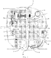
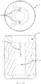
- said compressor comprises a housing 8, said housing being commonly hermetic, and an electric motor formed by a rotor 1 and stator 2.
- a rotating shaft 3 is operated in association with the rotor 1 of the electric motor; the rotor 1 comprising at least one internal wall 11 that faces the rotating shaft 3. It is worth noting that it is common to have an interference assembly between the rotor 1 and the rotating shaft 3 in order to be able to transmit the torque generated by the electric motor for the compression mechanism.
- a compressor block 4 is provided in order to partially accommodate the rotating shaft 3.
- An oil pump 6 is coupled to the shaft-rotor set and partially immersed in an oil reservoir 7 disposed in the lower portion of the housing 8 of the compressor.
- the rotating shaft 3 is provided with radial bearings, such as, for example, the radial bearings 5a and 5b, arranged in different positions in relation to said rotating shaft 3.
- the radial bearings 5a and 5b must receive lubrication from the lubricating oil of the oil reservoir 7.
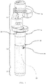
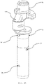
- the rotating shaft 3 As can be seen in more detail in Figure 2 for the purpose of understanding the lubrication system commonly used in hermetic compressors, it is possible to divide the rotating shaft 3 into a lower region 31, an upper region 32 and a rotating region 33.
- Said lower region 31 has the function of housing by interference the oil pump 6 disposed in the oil reservoir 7;
- said rotating region 33 bounded by the housing of the shaft in the block 4 and by the portion interfering with the rotor 1, contains a duct 36, an opening 37 and an external helical channel 38 which together feed with lubricating oil the radial bearings 5a and 5b located, respectively, at the end of the rotating region 33 and in the upper region 32 of the rotating shaft 3.
- the lubricating oil transport is performed by a lubricating oil pump, which acts in cooperation with the rotating shaft of the compressor that transports the oil with the aid of mechanical drag.
- the oil pump 6 is provided with a hole 39 in the lower region and, by centrifugal force, raises that oil until it finds the duct 36, which further accelerates the fluid.
- the helical channel 38 located outside the rotating region 33, has a mechanical pumping function, by dragging against the housing of the shaft in the compressor block 4.
- a secondary function performed by the lubricating oil is to remove heat from the electromechanical assembly and assist in its transmission to the environment outside the compressor through the hermetic housing. In most compressors, this oil flow is a result of the excess pumping of lubricating oil to the bearings which naturally returns to the bottom of the hermetic housing. However, it is also possible to direct part of the oil flow to specific points of the motor, promoting additional cooling that reduces the temperature of these components and, therefore, increases the life of the compressor as a whole.
- the document US9217434 entitled “COMPRESSOR HAVING DRIVE SHAFT WITH FLUID PASSAGES”, published on October 18, 2012 , presents a compressor that comprises a rotating shaft that presents several oil transport channels located internally to said shaft.
- the channels presented in this document make it possible to transport lubricating oil from an oil reservoir located at the bottom of the compressor housing to the top of the electric motor, with this flow being specifically applied to the cooling of the motor coils. It is noted that the same oil flow that runs through these internal channels is applied in the lubrication of bearings that support moving parts of the compressor.
- document KR547434 entitled “A COOLING STRUCTURE OF END-COIL FOR HERMETIC COMPRESSOR", published on October 24, 2005 , describes a compressor equipped with a rotor, an axis and a passage channel, this passage carrying lubricating oil from a pumping element.
- a concavity element is provided and comprises a series of radial openings that aim to distribute the flow of lubricating oil in the lower part of the stator. The purpose of the lubricating oil flow is to reduce the temperature/heat removal from the coils.
- An objective of the present invention is to provide a lubricating oil transport system that avoids the problems of the state of the art.
- the system according to the present invention consists of the fact that the concavity has a helicoid shape.
- the system according to the present invention consists of the fact that the circumferential channel has an external diameter smaller than the external diameter of the rotating shaft housing in the compressor block.
- system according to the present invention consists of the fact that the radial channel outlet is inscribed in a circle with a diameter larger than the outer diameter of the rotating shaft housing in the compressor block.
- the system according to the present invention consists of the fact that the concavity has an annular shape and the rotor does not need the circumferential channel, communicating the radial channel directly with said annular-shaped concavity.
- system according to the present invention consists of the fact that the rotating shaft does not need the concavity, directly communicating the restricting hole to the circumferential channel.
- the present invention also provides a system for transporting lubricating oil in a compressor, comprising:
- the system according to the present invention consists of the fact that the radial channel outlet is inscribed in a circle with a diameter larger than the outer diameter of the rotating shaft housing in the compressor block.
- system according to the present invention consists of the fact that there is a partial juxtaposition between the entrance of the radial channel and the outer diameter of the circumferential channel.
- the main objective of the present invention is to reveal a lubricating oil transport system in a hermetic compressor that uses configurations applied to the rotating shaft and applied to the rotor of the electric motor.
- the present invention also aims to reveal a lubricating oil transport system in a hermetic compressor that allows the provision of oil transport for the purpose of lubricating support bearings and for the purpose of cooling the upper region of the electric motor coils.
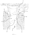
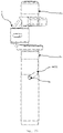
- a lubricating oil transport system is provided in a hermetic compressor for cooling the upper coils of the electric motor in addition to the normal lubricating oil transport system for the bearings and moving parts, as shown in Figure 3 .
- the lubricating oil transport system of the present invention is defined by the fact that the rotating shaft 3 comprises at least one concavity 35, said concavity 35 extends over part of the rotating surface 33, and a restrictor hole 34, said hole 34 communicates the concavity 35 with the internal region of the rotating shaft 3.
- the concavity 35 and the restrictor hole 34 are responsible for diverting a portion of lubricating oil, coming from the oil pump 6, from the internal region of the rotating shaft 3.
- Said concavity 35 in general, defines a type of recess formed in the rotating surface 33 of the rotating shaft 3, such concavity 35 being partially closed by the inner wall 11 of the rotor 1.
- the rotating surface 33 interacts with the inner wall 11 of the rotor 1, forming a type of pumping mechanism that operates by centrifugal force, depending on the operation of the compressor.
- the rotor 1 further comprises a circumferential channel 12 and at least one radial channel 13 extending through the inner wall 11 of the rotor 1.
- Said circumferential channel 12 cooperates with the radial channel 13, equally distributing the flow of lubricating oil provided by the concavity 35, regardless of the angular position of the rotor 1 in relation to the rotating shaft 3 and, consequently, in relation to the concavity 35.
- the maximum diameter of the circumferential channel 12 must be smaller than the minimum outer diameter of the rotating shaft 3 housing in the compressor block 4, in order to limit the vertical displacement of the rotating shaft 3 - rotor 1 set in relation to the compressor block 4.
- the length of the radial channel 13 must be dimensioned in such a way that its outlet is inscribed in a larger diameter than the same external diameter of the rotating shaft 3 housing in the compressor block 4, in order to ensure unrestricted flow of oil through the space 41 formed between the aluminum ring 14 of the rotor 1 and the compressor block 4, even under conditions where the vertical clearance between the rotor 1 and the rotating shaft 3 housing in the block compressor 4 is too small.
- the concavity 35 has a helicoid shape, extending in a spiral over part of the rotating surface 33.
- the recess must open towards the circumferential channel 12.
- This circumferential channel 12 also communicates with at least one radial channel 13.
- the concavity 35 has an annular shape, extending around the rotating surface 33.
- at least one upward radial channel 13 is provided in the inner wall 11 of the rotor 1 which communicates with the concavity 35 of the rotating shaft 3.
- the rotor 1 may or may not have the circumferential channel 12 on its inner wall.
- Figure 12 illustrates the rotor 1 provided with only the radial channel 13.
- the restrictor hole 34 is responsible for diverting part of the oil pumped by the pump 6 to the annular concavity 35, said concavity 35 makes the distribution of this oil flow until it finds the upward radial 13 channel, exiting into space 41 and finally being thrown against the coils of stator 1 on the top of the electric motor.
- Figure 18 illustrates the configuration of the rotor 1 for carrying out this second embodiment.
- a third alternative embodiment illustrated in Figures 19 to 25 , there is no concavity 35 on the rotating surface 33, only the restricted hole 34 remaining for communication with the internal part of the rotating shaft 3.
- at least one radial channel 13 is provided on the inner wall 11 of the rotor 1, said radial channel 13 communicating with the circumferential channel 12 located at a height of the rotor 1 at the same level as the restrictor hole 34.
- Said circumferential channel 12, provided on the inner wall of the rotor 1 ensures that a specific angular positioning of rotor 1 with rotating shaft 3 is not necessary in order to align the restrictor hole 34 with the radial channel 13.
- Figure 26 illustrates rotor 1 in this third embodiment.
- radial channels 13 are applied to the inner wall 11, said channels 13 disposed in order to guarantee the symmetry of the rotor 1 and avoid problems of unbalance.
- These radial channels 13 can and should follow the rotation angle of the aluminum bars of the rotor 1 cage and being obtained directly from the stamping of the rotor 1 blades.
- a fourth embodiment is illustrated in Figure 26 .
- This embodiment is only used in hermetic compressors in which the oil pump 6 is mounted by interference in relation to the internal wall 11 of the rotor 1.
- the rotating shaft 3 does not need the restrictor hole 34, which can remain with the original oil pumping system.
- the oil diversion for cooling the motor coils takes place in a section of the inner wall 11 between the upper part of the oil pump 6 and the lower region 31 of the rotating shaft 3, through a circumferential channel 12.
- the channel circumferential has a height h, illustrated in Figure 28 .
- This circumferential channel 12 communicates with at least one upward radial channel 13, which takes this oil flow into space 41 and, subsequently, to the coils located at the top of stator 1 of the electric motor, as shown in Figure 27 .
- the circumferential channel 12 can be obtained directly by stacking sheets of electric steel. However, this will cause the height h to be an integer multiple of the thickness of the blade of the electric rotor steel. If this height h results in an oil flow deviated for the cooling of the electric motor coils that affects the flow required for the lubrication of the radial bearings 5a and 5b, for example, an additional restriction can be provided by the partial juxtaposition of the outside diameter of the circumferential channel 12 with the diameter of the upward radial channel 13, as represented by the dimension dr in the detail of Figure 29 .
Landscapes
- Engineering & Computer Science (AREA)
- Mechanical Engineering (AREA)
- General Engineering & Computer Science (AREA)
- Motor Or Generator Cooling System (AREA)
- Compressor (AREA)
Abstract
Description
- The present invention relates to a compressor lubricating oil transport system that uses configurations applied to the rotating shaft and to the rotor of the electric motor to provide oil transportation for the purpose of lubricating the bearings of said rotating shaft and for purposes of cooling the upper region of the coils of said electric motor.
- As is known to those skilled in the art, hermetic compressors (usually reciprocating), provide for the use of lubricating oil to reduce friction and wear between moving components and, in particular, moving components that integrate the functional compression unit of the hermetic compressor, such as, for example, the eccentric shaft, the central rotating shaft, support bearings, among others. Lubricating oil is usually stored in a reservoir in the lower inner portion of the airtight housing.
- In this sense, it is mandatory that the lubricating oil, stored in the lower portion of the hermetic compressor housing, be transported to the moving elements that integrate the compression functional units (moving parts) of the hermetic compressor. Thus, it is common to take advantage of the movement of the compressor's own rotating shaft to transport or pump this lubricating oil to the regions where the oil is needed.
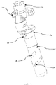
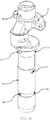
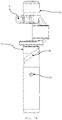
- As illustrated in
Figure 1 , said compressor comprises ahousing 8, said housing being commonly hermetic, and an electric motor formed by arotor 1 andstator 2. In addition, a rotatingshaft 3 is operated in association with therotor 1 of the electric motor; therotor 1 comprising at least oneinternal wall 11 that faces the rotatingshaft 3. It is worth noting that it is common to have an interference assembly between therotor 1 and the rotatingshaft 3 in order to be able to transmit the torque generated by the electric motor for the compression mechanism. - Additionally, a compressor block 4 is provided in order to partially accommodate the rotating
shaft 3. Anoil pump 6 is coupled to the shaft-rotor set and partially immersed in anoil reservoir 7 disposed in the lower portion of thehousing 8 of the compressor. - For proper operation of the mechanical systems of the compressor, the rotating
shaft 3 is provided with radial bearings, such as, for example, theradial bearings shaft 3. Theradial bearings oil reservoir 7. - As can be seen in more detail in
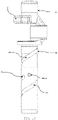
Figure 2 for the purpose of understanding the lubrication system commonly used in hermetic compressors, it is possible to divide the rotatingshaft 3 into alower region 31, an upper region 32 and arotating region 33. Saidlower region 31 has the function of housing by interference theoil pump 6 disposed in theoil reservoir 7; said rotatingregion 33, bounded by the housing of the shaft in the block 4 and by the portion interfering with therotor 1, contains aduct 36, an opening 37 and an externalhelical channel 38 which together feed with lubricating oil theradial bearings region 33 and in the upper region 32 of the rotatingshaft 3. - It is common in the art that the lubricating oil transport is performed by a lubricating oil pump, which acts in cooperation with the rotating shaft of the compressor that transports the oil with the aid of mechanical drag. In order to allow lubricating oil to enter the rotating
shaft 3, theoil pump 6 is provided with ahole 39 in the lower region and, by centrifugal force, raises that oil until it finds theduct 36, which further accelerates the fluid. Thehelical channel 38, located outside therotating region 33, has a mechanical pumping function, by dragging against the housing of the shaft in the compressor block 4. - A secondary function performed by the lubricating oil is to remove heat from the electromechanical assembly and assist in its transmission to the environment outside the compressor through the hermetic housing. In most compressors, this oil flow is a result of the excess pumping of lubricating oil to the bearings which naturally returns to the bottom of the hermetic housing. However, it is also possible to direct part of the oil flow to specific points of the motor, promoting additional cooling that reduces the temperature of these components and, therefore, increases the life of the compressor as a whole.
- For example, the document
US9217434, entitled "COMPRESSOR HAVING DRIVE SHAFT WITH FLUID PASSAGES", published on October 18, 2012 - However, it is observed that the use of the oil flow that is carried through the channels internal to the rotating shaft, both for cooling purposes and for lubrication purposes, can cause failures in the oil supply, which would lead to problems in the lubrication of the bearings. In addition, there may be a reduction in the pumping pressure, since the flow of oil in the internal channels is diffuse, being divided along the rotating shaft.
- In addition, document
KR547434, entitled "A COOLING STRUCTURE OF END-COIL FOR HERMETIC COMPRESSOR", published on October 24, 2005 - However, the solution proposed in this document does not allow to cool the upper part of the coils, which would continue without an additional oil flow. The durability of electrical insulators would continue to be determined by the hottest point of the coils at the top.
- Additionally, the document
US9617985, entitled "HERMETIC RECIPROCATING COMPRESSOR", published on October 31, 2013 - However, this document does not describe a system in which the external channels in the shaft cooperate with the channel system in the rotor to ensure an oil flow to the bearings without the amount of oil supplied by the pumping system to the bearings being impaired.
- An objective of the present invention is to provide a lubricating oil transport system that avoids the problems of the state of the art.
- Such objective is achieved by means of system for transporting lubricating oil in a compressor, comprising:
- a housing;
- an electric motor comprising a rotor and a stator ,
- the rotor comprising at least one inner wall;
- an oil pump and an oil reservoir arranged inside the housing;
- a rotary shaft as an integral part of the electric motor;
- a compressor block capable of housing, at least partially, the rotary shaft;
- the rotary shaft supported by at least one radial bearing;
- the rotary axis comprising a lower region, an upper region and a rotating surface;
- wherein the rotating shaft has at least one concavity that extends over part of the rotating surface in contact with the internal surface of the rotor and at least one restrictor hole which communicates with the internal region of the rotating shaft and with the concavity;
- the rotor comprises a circumferential channel and at least one radial channel extending through the inner wall of the rotor;
- the radial channel is arranged around the circumferential channel;
- said circumferential channel) and the radial channel communicating with the concavity;
- the circumferential channel, the radial channel and the concavity transport oil for cooling the upper part of the rotor and the stator.
- Conveniently, the system according to the present invention consists of the fact that the concavity has a helicoid shape.
- Additionally, the system according to the present invention consists of the fact that the circumferential channel has an external diameter smaller than the external diameter of the rotating shaft housing in the compressor block.
- In addition, the system according to the present invention consists of the fact that the radial channel outlet is inscribed in a circle with a diameter larger than the outer diameter of the rotating shaft housing in the compressor block.
- Furthermore, the system according to the present invention consists of the fact that the concavity has an annular shape and the rotor does not need the circumferential channel, communicating the radial channel directly with said annular-shaped concavity.
- Additionally, the system according to the present invention consists of the fact that the rotating shaft does not need the concavity, directly communicating the restricting hole to the circumferential channel.
- The present invention also provides a system for transporting lubricating oil in a compressor, comprising:
- a housing;
- an electric motor comprising a rotor and a stator,
- the rotor comprising at least one inner wall;
- an oil pump and an oil reservoir arranged inside the housing;
- a rotating shaft as an integral part of the electric motor;
- a compressor block capable of housing, at least partially, the rotating shaft;
- the rotating shaft supported by at least one radial bearing;
- the rotating shaft comprising a lower region, an upper region and a rotating surface;
- wherein the rotor has at least one radial channel arranged around a circumferential channel;
- wherein the circumferential channel extends over at least part of the inner wall of the rotor;
- wherein the circumferential channel is located at an intermediate level between the upper part of the oil pump and the lower region of the rotating shaft; and
- wherein the circumferential channel and the radial channel carry oil for cooling the upper part of the rotor and the stator.
- Conveniently, the system according to the present invention consists of the fact that the radial channel outlet is inscribed in a circle with a diameter larger than the outer diameter of the rotating shaft housing in the compressor block.
- Additionally, the system according to the present invention consists of the fact that there is a partial juxtaposition between the entrance of the radial channel and the outer diameter of the circumferential channel.
- Thus, the main objective of the present invention is to reveal a lubricating oil transport system in a hermetic compressor that uses configurations applied to the rotating shaft and applied to the rotor of the electric motor.
- Furthermore, the present invention also aims to reveal a lubricating oil transport system in a hermetic compressor that allows the provision of oil transport for the purpose of lubricating support bearings and for the purpose of cooling the upper region of the electric motor coils.
- Finally, it is the objective of the present invention to provide a lubricating oil transport system in a hermetic compressor that does not present lubricating oil flow failures or lubricating oil pumping pressure drop.
- The preferred embodiments of the present invention are described in detail based on the Figures listed below.
-
Figure 1 illustrates a sectional view of the compressor illustrating the state of the art, with the conventional oil pumping system exclusively for the compressor bearings. -
Figure 2 illustrates a perspective view of a rotating shaft of the state of the art, with the oil pumping system exclusively for the compressor bearings. -
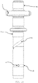
Figure 3 illustrates a sectional view of the first embodiment of the compressor showing the lubricating oil transport system including the arrangement for cooling the engine coils by the oil jet. -
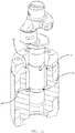
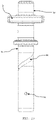
Figure 4 illustrates a perspective view of the first embodiment of the rotor-rotating shaft set with the rotor in section to show the helical concavities external to the shaft and how they cooperate with the channels placed on the top of the rotor according to present invention. -
Figure 5 is another perspective of the first embodiment of the shaft-rotor set, with the rotor in horizontal section, to show the circumferential channel and the radial channels and how they cooperate with the end of the external helical concavities of the shaft according to the present invention. -
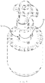
Figure 6 illustrates a perspective view of the first embodiment of the rotating shaft showing the concavities on the rotating surface according to the present invention. -
Figure 7 illustrates an anterior view of the first embodiment of the rotating shaft, with the helical concavities for cooling the motor at the bottom and the helical concavity for lubricating the bearings at the top of the rotating region of the shaft. It is also possible to see the restrictor hole for cooling the motor at the beginning of the helical cavity at the lower region of the shaft according to the present invention. -
Figure 8 illustrates a right-side view of the first embodiment of the rotating shaft, showing the oil feed hole of the helical concavity for lubricating the bearings in the top of the rotating region of the shaft according to the present invention. -
Figure 9 illustrates a posterior view of the first embodiment of the rotating shaft, with the helical concavities for cooling the motor at the bottom and the helical concavity for lubricating the bearings at the top of the rotating region of the shaft. It is also possible to see a second restrictor hole for cooling the motor at the beginning of a second helical cavity at the lower region of the shaft according to the present invention. -
Figure 10 illustrates a left side view of the first embodiment of the rotating shaft, showing the oil degassing hole for lubricating the bearings at the end of the shaft region with interface to the rotor according to the present invention. -
Figure 11 illustrates a top view of the first embodiment of the rotor showing the radial channels and the circumferential channel at the top and a vertical sectional view of the rotor, showing the internal configuration of the radial and circumferential channels of the rotor according to present invention. -
Figure 12 illustrates a perspective view of the second embodiment of the shaft-rotor set, without the need for upward helical concavities on the rotating shaft for motor cooling, but with the restrictor hole and a circumferential communication concavity with the rotor according to the present invention. -
Figure 13 illustrates a perspective view of the second embodiment of the rotating shaft with the configuration of the circumferential channel on the external surface of the rotating shaft according to the present invention. -
Figure 14 illustrates an anterior view of the second embodiment of the rotating shaft, with the circumferential channel for cooling the motor at the bottom and the helical concavity for lubricating the bearings at the top of the rotating region of the shaft. It is also possible to see the restrictor hole for cooling the motor in the middle of the circumferential channel at the lower region of the shaft according to the present invention. -
Figure 15 illustrates a right-side view of the second embodiment of the rotating shaft, showing the oil supply hole of the helical concavity for lubricating the bearings in the top of the rotating region of the shaft according to the present invention. -
Figure 16 illustrates a posterior view of the second embodiment of the rotating shaft, with the circumferential channel for cooling the motor at the bottom and the helical concavity for lubricating the bearings at the top of the rotating region of the axis. It is also possible to see a second restrictor hole for cooling the motor in the middle of the circumferential channel at the lower region of the shaft according to the present invention. -
Figure 17 illustrates a left side view of the second embodiment of the rotating shaft, showing the oil degassing hole for lubricating the bearings at the end of the shaft region with interface to the rotor according to the present invention. -
Figure 18 illustrates a top view of the second embodiment of the rotor, with upward radial channels and a sectional view, showing the internal arrangement of these channels according to the present invention. -
Figure 19 illustrates a perspective view of the third embodiment of the shaft-rotor set, without cavities in the shaft for cooling the motor, only with the restrictor hole for oil passage according to the present invention. -
Figure 20 illustrates a perspective view of the third embodiment of the rotating shaft, with only the restrictor hole for oil passage according to the present invention. -
Figure 21 illustrates an anterior view of the third embodiment of the rotating shaft with the restrictor hole at the bottom and the helical concavity for transporting oil to the bearings at the top of the rotating region of the axis according to the present invention. -
Figure 22 illustrates a right-side view of the third embodiment of the rotating shaft, showing the il supply hole of the helical concavity for lubricating the bearings in the top of the rotating region of the shaft according to the present invention. -
Figure 23 illustrates a posterior view of the third embodiment of the rotating shaft, with a second restrictor hole for cooling the motor at the bottom and the helical concavity for lubricating the bearings at the top of the rotating region of the shaft according to the present invention. -
Figure 24 illustrates a left side view of the third embodiment of the rotating shaft, showing the oil degassing hole for lubricating the bearings at the end of the shaft region with interface with the rotor according to the present invention. -
Figure 25 illustrates a top view of the third embodiment of the rotor, with a circumferential channel located at an intermediate height in relation to the restrictor hole of the rotating shaft and upward radial channels responsible for allowing the passage of oil for cooling the motor to the top of the rotor. A cross-sectional view is also presented to facilitate understanding of the internal configuration of the rotor according to the present invention. -
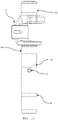
Figure 26 illustrates a sectional view of a compressor according to a fourth embodiment of the motor cooling system by oil jet, when the oil pump is coupled to the rotor according to the present invention. -
Figure 27 illustrates a perspective view of the fourth embodiment of the shaft-rotor-oil pump set, with a partial cut applied to the rotor illustrating its internal configuration and the relative position of the circumferential channel and ascending radial channels in relation to the rotating shaft and the oil pump according to the present invention. -
Figure 28 illustrates an anterior view of the fourth embodiment of the shaft-rotor-oil pump set, with a partial cut applied to the rotor illustrating its internal configuration and the relative position of the circumferential channel and ascending radial channels in relation to the rotating shaft and the oil pump. A detail is provided indicating the height "h" of the circumferential channel, now also responsible for defining the flow of oil diverted for cooling the motor coils according to the present invention. -
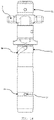
Figure 29 illustrates a horizontal section of the fourth embodiment of the shaft-rotor-oil pump set located immediately above the circumferential channel in the rotor, illustrating in detail an alternative configuration for the transition between the circumferential channel and the ascending radial channels, which can be added to suit the oil flow for cooling the motor coils according to the present invention. - In accordance with the general objectives of the present invention, a lubricating oil transport system is provided in a hermetic compressor for cooling the upper coils of the electric motor in addition to the normal lubricating oil transport system for the bearings and moving parts, as shown in
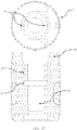
Figure 3 . - According to
Figure 4 , the lubricating oil transport system of the present invention is defined by the fact that therotating shaft 3 comprises at least oneconcavity 35, saidconcavity 35 extends over part of therotating surface 33, and arestrictor hole 34, saidhole 34 communicates theconcavity 35 with the internal region of therotating shaft 3. Theconcavity 35 and therestrictor hole 34 are responsible for diverting a portion of lubricating oil, coming from theoil pump 6, from the internal region of therotating shaft 3. - Said
concavity 35, in general, defines a type of recess formed in therotating surface 33 of therotating shaft 3,such concavity 35 being partially closed by theinner wall 11 of therotor 1. Thus, for the lubricating oil be transported, the rotatingsurface 33 interacts with theinner wall 11 of therotor 1, forming a type of pumping mechanism that operates by centrifugal force, depending on the operation of the compressor. - According to
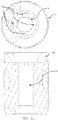
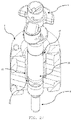
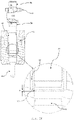
Figures 4 and5 , therotor 1 further comprises acircumferential channel 12 and at least oneradial channel 13 extending through theinner wall 11 of therotor 1. Saidcircumferential channel 12 cooperates with theradial channel 13, equally distributing the flow of lubricating oil provided by theconcavity 35, regardless of the angular position of therotor 1 in relation to therotating shaft 3 and, consequently, in relation to theconcavity 35. According toFigure 11 , the maximum diameter of thecircumferential channel 12 must be smaller than the minimum outer diameter of therotating shaft 3 housing in the compressor block 4, in order to limit the vertical displacement of the rotating shaft 3 -rotor 1 set in relation to the compressor block 4. On the other hand, the length of theradial channel 13 must be dimensioned in such a way that its outlet is inscribed in a larger diameter than the same external diameter of therotating shaft 3 housing in the compressor block 4, in order to ensure unrestricted flow of oil through thespace 41 formed between thealuminum ring 14 of therotor 1 and the compressor block 4, even under conditions where the vertical clearance between therotor 1 and therotating shaft 3 housing in the block compressor 4 is too small. - In a first preferred embodiment, the
concavity 35 has a helicoid shape, extending in a spiral over part of therotating surface 33. The recess must open towards thecircumferential channel 12. Thiscircumferential channel 12 also communicates with at least oneradial channel 13. - The number of
concavities 35 andrestrictor holes 34 depend on the cooling need of thestator 2, where the electric motor coils are housed.Figures 6 to 10 illustrate several views of therotating shaft 3. Likewise, the number ofradial channels 13 in the rotor must allow the free flow of oil intospace 41 and in a way provide a symmetry of the rotor, in order to leave it balanced, as illustrated inFigure 11 . - In a second possible embodiment, illustrated in
Figures 12 to 17 , theconcavity 35 has an annular shape, extending around the rotatingsurface 33. In this configuration, at least one upwardradial channel 13 is provided in theinner wall 11 of therotor 1 which communicates with theconcavity 35 of therotating shaft 3. In this case, therotor 1 may or may not have thecircumferential channel 12 on its inner wall.Figure 12 illustrates therotor 1 provided with only theradial channel 13. Therestrictor hole 34 is responsible for diverting part of the oil pumped by thepump 6 to theannular concavity 35, saidconcavity 35 makes the distribution of this oil flow until it finds theupward radial 13 channel, exiting intospace 41 and finally being thrown against the coils ofstator 1 on the top of the electric motor. In addition,Figure 18 illustrates the configuration of therotor 1 for carrying out this second embodiment. - In a third alternative embodiment, illustrated in
Figures 19 to 25 , there is noconcavity 35 on therotating surface 33, only the restrictedhole 34 remaining for communication with the internal part of therotating shaft 3. In this embodiment, at least oneradial channel 13 is provided on theinner wall 11 of therotor 1, saidradial channel 13 communicating with thecircumferential channel 12 located at a height of therotor 1 at the same level as therestrictor hole 34. Saidcircumferential channel 12, provided on the inner wall of therotor 1, ensures that a specific angular positioning ofrotor 1 withrotating shaft 3 is not necessary in order to align therestrictor hole 34 with theradial channel 13.Figure 26 illustratesrotor 1 in this third embodiment. - In any constructive situation of the
rotor 1, preferably two or moreradial channels 13 are applied to theinner wall 11, saidchannels 13 disposed in order to guarantee the symmetry of therotor 1 and avoid problems of unbalance. Theseradial channels 13 can and should follow the rotation angle of the aluminum bars of therotor 1 cage and being obtained directly from the stamping of therotor 1 blades. - The previous embodiments can be applied to compressors whose
oil pump 6 is mounted by internal or external interference to thelower region 31 of therotating shaft 3, or even by interference in relation to theinternal wall 11 of therotor 1, the deviation of oil for cooling the coil being carried out by therestrictor hole 34 provided on therotating shaft 3. - A fourth embodiment is illustrated in
Figure 26 . This embodiment is only used in hermetic compressors in which theoil pump 6 is mounted by interference in relation to theinternal wall 11 of therotor 1. In this embodiment, therotating shaft 3 does not need therestrictor hole 34, which can remain with the original oil pumping system. In this way, the oil diversion for cooling the motor coils takes place in a section of theinner wall 11 between the upper part of theoil pump 6 and thelower region 31 of therotating shaft 3, through acircumferential channel 12. The channel circumferential has a height h, illustrated inFigure 28 . Thiscircumferential channel 12 communicates with at least one upwardradial channel 13, which takes this oil flow intospace 41 and, subsequently, to the coils located at the top ofstator 1 of the electric motor, as shown inFigure 27 . - The
circumferential channel 12 can be obtained directly by stacking sheets of electric steel. However, this will cause the height h to be an integer multiple of the thickness of the blade of the electric rotor steel. If this height h results in an oil flow deviated for the cooling of the electric motor coils that affects the flow required for the lubrication of theradial bearings circumferential channel 12 with the diameter of the upwardradial channel 13, as represented by the dimension dr in the detail ofFigure 29 . - It is important to note that the above descriptions have the sole purpose of describing in particular exemplary embodiments of the present invention. Therefore, it is clear that modifications, variations and constructive combinations of the elements that perform the same function in substantially the same way to achieve the same results, remain within the scope of protection defined by the attached claims.
Claims (9)
- System for transporting lubricating oil in a compressor, comprising:a housing (8);an electric motor comprising a rotor (1) and a stator (2),the rotor (1) comprising at least one inner wall (11);an oil pump (6) and an oil reservoir (7) arranged inside the housing (8);a rotary shaft (3) as an integral part of the electric motor;a compressor block (4) capable of housing, at least partially, the rotary shaft (3);the rotary shaft (3) supported by at least one radial bearing (5a, 5b);the rotary axis (3) comprising a lower region (31), an upper region (32) and a rotating surface (33);characterized in that the rotating shaft (3) has at least one concavity (35) that extends over part of the rotating surface (33) in contact with the internal surface (11) of the rotor (1) and at least one restrictor hole (34) which communicates with the internal region of the rotating shaft (3) and with the concavity (35);the rotor (1) comprises a circumferential channel (12) and at least one radial channel (13) extending through the inner wall (11) of the rotor (1);the radial channel (13) is arranged around the circumferential channel (12);said circumferential channel (12) and the radial channel (13) communicating with the concavity (35);the circumferential channel (12), the radial channel (13) and the concavity (35) transport oil for cooling the upper part of the rotor (1) and the stator (2).
- System for transporting lubricating oil in a compressor, according to claim 1, characterized in that the concavity (35) has a helicoid shape.
- System for transporting lubricating oil in a compressor, according to claim 1, characterized in that the circumferential channel (12) has an external diameter smaller than the external diameter of the rotating shaft (3) housing in the compressor block (4).
- System for transporting lubricating oil in a compressor, according to claim 1, characterized in that the radial channel outlet (13) is inscribed in a circle with a diameter larger than the outer diameter of the rotating shaft (3) housing in the compressor block (4).
- System for transporting lubricating oil in a compressor, according to claim 1, characterized in that the concavity (35) has an annular shape and the rotor (1) does not need the circumferential channel (12), communicating the radial channel (13) directly with said annular-shaped concavity (35).
- System for transporting lubricating oil in a compressor, according to claim 1, characterized in that the rotating shaft (3) does not need the concavity (35), directly communicating the restricting hole (34) to the circumferential channel (12).
- System for transporting lubricating oil in a compressor, comprising:a housing (8);an electric motor comprising a rotor (1) and a stator (2),the rotor (1) comprising at least one inner wall (11);an oil pump (6) and an oil reservoir (7) arranged inside the housing (8);a rotating shaft (3) as an integral part of the electric motor;a compressor block (4) capable of housing, at least partially, the rotating shaft (3);the rotating shaft (3) supported by at least one radial bearing (5a, 5b);the rotating shaft (3) comprising a lower region (31), an upper region (32) and a rotating surface (33);characterized in that the rotor (1) has at least one radial channel (13) arranged around a circumferential channel (12);wherein the circumferential channel (12) extends over at least part of the inner wall (11) of the rotor (1);wherein the circumferential channel (12) is located at an intermediate level between the upper part of the oil pump (6) and the lower region (31) of the rotating shaft (3); andwherein the circumferential channel (12) and the radial channel (13) carry oil for cooling the upper part of the rotor (1) and the stator (2).
- Lubricating oil transport system, according to claim 7, characterized in that the radial channel (13) outlet is inscribed in a circle with a diameter larger than the outer diameter of the rotating shaft (13) housing in the compressor block (4).
- Lubricating oil transport system, according to claim 7, characterized in that there is a partial juxtaposition between the entrance of the radial channel (13) and the outer diameter of the circumferential channel (12).
Applications Claiming Priority (3)
| Application Number | Priority Date | Filing Date | Title |
|---|---|---|---|
| BR102020001095A BR102020001095A2 (en) | 2020-01-17 | 2020-01-17 | compressor lubricating oil transport system |
| BR102021000804-0A BR102021000804A2 (en) | 2020-01-17 | 2021-01-15 | Compressor lubricating oil transport system |
| PCT/BR2021/050019 WO2021142525A1 (en) | 2020-01-17 | 2021-01-18 | System for transporting lubricating oil in a compressor |
Publications (1)
| Publication Number | Publication Date |
|---|---|
| EP4092271A1 true EP4092271A1 (en) | 2022-11-23 |
Family
ID=74758452
Family Applications (1)
| Application Number | Title | Priority Date | Filing Date |
|---|---|---|---|
| EP21708105.8A Pending EP4092271A1 (en) | 2020-01-17 | 2021-01-18 | System for transporting lubricating oil in a compressor |
Country Status (4)
| Country | Link |
|---|---|
| US (1) | US12359657B2 (en) |
| EP (1) | EP4092271A1 (en) |
| CN (1) | CN115066555A (en) |
| WO (1) | WO2021142525A1 (en) |
Cited By (2)
| Publication number | Priority date | Publication date | Assignee | Title |
|---|---|---|---|---|
| EP4435261A1 (en) | 2023-03-21 | 2024-09-25 | Secop GmbH | Refrigerant compressor |
| EP4435260A1 (en) | 2023-03-21 | 2024-09-25 | Secop GmbH | Refrigerant compressor |
Families Citing this family (1)
| Publication number | Priority date | Publication date | Assignee | Title |
|---|---|---|---|---|
| JP7507961B2 (en) * | 2021-04-14 | 2024-06-28 | 安徽美芝制冷設備有限公司 | Crankshafts, inverter compressors and refrigeration equipment |
Family Cites Families (16)
| Publication number | Priority date | Publication date | Assignee | Title |
|---|---|---|---|---|
| US3276677A (en) | 1964-04-07 | 1966-10-04 | Trask Allen | Lubrication system for compressor shaft journals |
| DE1628157C3 (en) * | 1968-02-01 | 1973-10-11 | Danfoss A/S, Nordborg (Daenemark) | Device for cooling an encapsulated motor compressor, in particular a clamping machine |
| US3848702A (en) * | 1972-10-02 | 1974-11-19 | Copeland Corp | Lubricating system for vertical machine elements |
| US4400142A (en) | 1981-05-04 | 1983-08-23 | Carrier Corporation | Motor-compressor unit |
| SU1435812A1 (en) * | 1987-04-10 | 1988-11-07 | Киевское Научно-Производственное Объединение "Электробытприбор" | Hermetic refrigerant compressor |
| US5007808A (en) * | 1989-12-15 | 1991-04-16 | Carrier Corporation | Slotted rotor lubrication system |
| BR9201761A (en) * | 1992-05-04 | 1993-11-09 | Brasil Compressores Sa | OIL PUMP FOR HERMETIC VARIABLE SPEED COMPRESSOR |
| JP4759862B2 (en) * | 2001-07-16 | 2011-08-31 | パナソニック株式会社 | Hermetic electric compressor |
| DE60136231D1 (en) * | 2001-12-17 | 2008-11-27 | Lg Electronics Inc | COMPRESSOR WITH DOUBLE-SIZED CONVEYING POWER |
| KR100538940B1 (en) * | 2003-11-28 | 2005-12-27 | 삼성광주전자 주식회사 | Hermetic compressor |
| KR100547434B1 (en) | 2004-04-19 | 2006-01-31 | 엘지전자 주식회사 | End coil cooling structure of hermetic compressor |
| KR20060117480A (en) * | 2005-05-11 | 2006-11-17 | 삼성광주전자 주식회사 | Hermetic compressor |
| US9217434B2 (en) | 2011-04-15 | 2015-12-22 | Emerson Climate Technologies, Inc. | Compressor having drive shaft with fluid passages |
| KR101910656B1 (en) | 2012-04-25 | 2018-10-23 | 삼성전자주식회사 | Hermetic reciprocating compressor |
| KR101483519B1 (en) * | 2012-05-15 | 2015-01-16 | 삼성전자 주식회사 | Hermetic reciprocating compressor |
| CN110662902B (en) * | 2017-05-23 | 2022-03-25 | 松下电器制冷装置新加坡 | Hermetic refrigeration compressors and refrigeration units |
-
2021
- 2021-01-18 WO PCT/BR2021/050019 patent/WO2021142525A1/en not_active Ceased
- 2021-01-18 EP EP21708105.8A patent/EP4092271A1/en active Pending
- 2021-01-18 US US17/792,911 patent/US12359657B2/en active Active
- 2021-01-18 CN CN202180009585.1A patent/CN115066555A/en active Pending
Cited By (5)
| Publication number | Priority date | Publication date | Assignee | Title |
|---|---|---|---|---|
| EP4435261A1 (en) | 2023-03-21 | 2024-09-25 | Secop GmbH | Refrigerant compressor |
| EP4435260A1 (en) | 2023-03-21 | 2024-09-25 | Secop GmbH | Refrigerant compressor |
| WO2024194438A1 (en) | 2023-03-21 | 2024-09-26 | Secop Gmbh | Refrigerant compressor |
| WO2024194434A1 (en) | 2023-03-21 | 2024-09-26 | Secop Gmbh | Refrigerant compressor |
| CN120677309A (en) * | 2023-03-21 | 2025-09-19 | 思科普有限公司 | Refrigerant compressor |
Also Published As
| Publication number | Publication date |
|---|---|
| US20230065792A1 (en) | 2023-03-02 |
| WO2021142525A1 (en) | 2021-07-22 |
| US12359657B2 (en) | 2025-07-15 |
| CN115066555A (en) | 2022-09-16 |
Similar Documents
| Publication | Publication Date | Title |
|---|---|---|
| US12359657B2 (en) | System for transporting lubricating oil in a compressor | |
| KR100749040B1 (en) | Scroll compressor | |
| RU2107192C1 (en) | Rotary screw compressor | |
| US10844759B2 (en) | Variable speed cooling compressor including lubricating oil pumping system | |
| EP0433212B1 (en) | Slotted rotor lubrication system | |
| US4543047A (en) | Rotary compressor | |
| EP2212558B1 (en) | Fixation arrangement for an oil pump in a refrigeration compressor | |
| AU2016222258B2 (en) | A self-lubricating pump arrangement | |
| US4850819A (en) | Motor compressor bearing assembly | |
| US20250067264A1 (en) | Compressor | |
| US6540474B2 (en) | Side-channel pump | |
| US20250341206A1 (en) | System for transporting lubricating oil in a compressor | |
| EP4435261A1 (en) | Refrigerant compressor | |
| US12546312B2 (en) | Oil pump for a motor vehicle | |
| WO2021113943A1 (en) | Reciprocating hermetic compressor with axial flux motor | |
| BR102021000804A2 (en) | Compressor lubricating oil transport system | |
| JP3356460B2 (en) | Hermetic compressor | |
| WO2016169348A1 (en) | Scroll compressor and driving shaft for scroll compressor | |
| EP3394446B1 (en) | Positive displacement vane pump | |
| CN118564462B (en) | Compressor thrust structure and compressor | |
| CN112983994B (en) | Main bearing pedestal and scroll compressor | |
| EP4435260B1 (en) | Refrigerant compressor | |
| CN117514773A (en) | Scroll for scroll compressor and scroll compressor | |
| JPH07233794A (en) | Horizontal rotary compressor | |
| WO2021212772A1 (en) | Scroll compressor |
Legal Events
| Date | Code | Title | Description |
|---|---|---|---|
| STAA | Information on the status of an ep patent application or granted ep patent |
Free format text: STATUS: UNKNOWN |
|
| STAA | Information on the status of an ep patent application or granted ep patent |
Free format text: STATUS: THE INTERNATIONAL PUBLICATION HAS BEEN MADE |
|
| PUAI | Public reference made under article 153(3) epc to a published international application that has entered the european phase |
Free format text: ORIGINAL CODE: 0009012 |
|
| STAA | Information on the status of an ep patent application or granted ep patent |
Free format text: STATUS: REQUEST FOR EXAMINATION WAS MADE |
|
| 17P | Request for examination filed |
Effective date: 20220804 |
|
| AK | Designated contracting states |
Kind code of ref document: A1 Designated state(s): AL AT BE BG CH CY CZ DE DK EE ES FI FR GB GR HR HU IE IS IT LI LT LU LV MC MK MT NL NO PL PT RO RS SE SI SK SM TR |
|
| DAV | Request for validation of the european patent (deleted) | ||
| DAX | Request for extension of the european patent (deleted) | ||
| STAA | Information on the status of an ep patent application or granted ep patent |
Free format text: STATUS: EXAMINATION IS IN PROGRESS |
|
| 17Q | First examination report despatched |
Effective date: 20240930 |