EP4091701A1 - Carbon dioxide recovery system - Google Patents
Carbon dioxide recovery system Download PDFInfo
- Publication number
- EP4091701A1 EP4091701A1 EP22173715.8A EP22173715A EP4091701A1 EP 4091701 A1 EP4091701 A1 EP 4091701A1 EP 22173715 A EP22173715 A EP 22173715A EP 4091701 A1 EP4091701 A1 EP 4091701A1
- Authority
- EP
- European Patent Office
- Prior art keywords
- carbon dioxide
- adsorbent
- working electrode
- electrons
- recovery system
- Prior art date
- Legal status (The legal status is an assumption and is not a legal conclusion. Google has not performed a legal analysis and makes no representation as to the accuracy of the status listed.)
- Pending
Links
- CURLTUGMZLYLDI-UHFFFAOYSA-N Carbon dioxide Chemical compound O=C=O CURLTUGMZLYLDI-UHFFFAOYSA-N 0.000 title claims abstract description 427
- 229910002092 carbon dioxide Inorganic materials 0.000 title claims abstract description 371
- 238000011084 recovery Methods 0.000 title claims abstract description 66
- 239000001569 carbon dioxide Substances 0.000 title claims abstract description 52
- 239000003463 adsorbent Substances 0.000 claims abstract description 141
- 238000003487 electrochemical reaction Methods 0.000 claims abstract description 6
- 238000001179 sorption measurement Methods 0.000 claims description 39
- 239000007789 gas Substances 0.000 claims description 36
- 239000000463 material Substances 0.000 claims description 29
- 239000002001 electrolyte material Substances 0.000 claims description 24
- 150000002484 inorganic compounds Chemical group 0.000 claims description 18
- 229910010272 inorganic material Inorganic materials 0.000 claims description 18
- OKTJSMMVPCPJKN-UHFFFAOYSA-N Carbon Chemical compound [C] OKTJSMMVPCPJKN-UHFFFAOYSA-N 0.000 claims description 16
- 239000003575 carbonaceous material Substances 0.000 claims description 16
- WOCIAKWEIIZHES-UHFFFAOYSA-N ruthenium(iv) oxide Chemical compound O=[Ru]=O WOCIAKWEIIZHES-UHFFFAOYSA-N 0.000 claims description 16
- 150000002500 ions Chemical class 0.000 claims description 13
- 125000002524 organometallic group Chemical group 0.000 claims description 12
- 150000002894 organic compounds Chemical group 0.000 claims description 11
- 239000002184 metal Substances 0.000 claims description 9
- 229910052751 metal Inorganic materials 0.000 claims description 9
- FNQJDLTXOVEEFB-UHFFFAOYSA-N 1,2,3-benzothiadiazole Chemical compound C1=CC=C2SN=NC2=C1 FNQJDLTXOVEEFB-UHFFFAOYSA-N 0.000 claims description 8
- 239000005964 Acibenzolar-S-methyl Substances 0.000 claims description 8
- 239000011148 porous material Substances 0.000 claims description 8
- 229910052717 sulfur Inorganic materials 0.000 claims description 7
- 229910052757 nitrogen Inorganic materials 0.000 claims description 6
- 239000006229 carbon black Substances 0.000 claims description 5
- CWQXQMHSOZUFJS-UHFFFAOYSA-N molybdenum disulfide Chemical compound S=[Mo]=S CWQXQMHSOZUFJS-UHFFFAOYSA-N 0.000 claims description 5
- 125000003118 aryl group Chemical group 0.000 claims description 4
- 150000004770 chalcogenides Chemical class 0.000 claims description 4
- 229910052961 molybdenite Inorganic materials 0.000 claims description 4
- 229910052982 molybdenum disulfide Inorganic materials 0.000 claims description 4
- 150000001491 aromatic compounds Chemical class 0.000 claims description 3
- 229910021393 carbon nanotube Inorganic materials 0.000 claims description 3
- 239000002041 carbon nanotube Substances 0.000 claims description 3
- 229910021389 graphene Inorganic materials 0.000 claims description 3
- 229910052809 inorganic oxide Inorganic materials 0.000 claims description 3
- 150000004767 nitrides Chemical class 0.000 claims description 2
- 229920002554 vinyl polymer Polymers 0.000 claims description 2
- 125000004433 nitrogen atom Chemical group N* 0.000 claims 1
- XKJCHHZQLQNZHY-UHFFFAOYSA-N phthalimide Chemical compound C1=CC=C2C(=O)NC(=O)C2=C1 XKJCHHZQLQNZHY-UHFFFAOYSA-N 0.000 claims 1
- 125000004434 sulfur atom Chemical group 0.000 claims 1
- 239000000126 substance Substances 0.000 description 33
- 239000000758 substrate Substances 0.000 description 17
- 239000011883 electrode binding agent Substances 0.000 description 14
- 238000002336 sorption--desorption measurement Methods 0.000 description 11
- 238000000034 method Methods 0.000 description 10
- 230000000052 comparative effect Effects 0.000 description 8
- 238000010586 diagram Methods 0.000 description 8
- 230000005684 electric field Effects 0.000 description 7
- 239000002608 ionic liquid Substances 0.000 description 7
- NUJOXMJBOLGQSY-UHFFFAOYSA-N manganese dioxide Chemical compound O=[Mn]=O NUJOXMJBOLGQSY-UHFFFAOYSA-N 0.000 description 6
- -1 polytetrafluoroethylene Polymers 0.000 description 6
- 239000012495 reaction gas Substances 0.000 description 6
- 150000001768 cations Chemical class 0.000 description 5
- 238000007599 discharging Methods 0.000 description 5
- 239000000446 fuel Substances 0.000 description 5
- 229910021645 metal ion Inorganic materials 0.000 description 5
- 239000013148 Cu-BTC MOF Substances 0.000 description 4
- 238000006243 chemical reaction Methods 0.000 description 4
- 150000001875 compounds Chemical class 0.000 description 4
- NJMWOUFKYKNWDW-UHFFFAOYSA-N 1-ethyl-3-methylimidazolium Chemical compound CCN1C=C[N+](C)=C1 NJMWOUFKYKNWDW-UHFFFAOYSA-N 0.000 description 3
- 230000000274 adsorptive effect Effects 0.000 description 3
- 229910052799 carbon Inorganic materials 0.000 description 3
- 230000009881 electrostatic interaction Effects 0.000 description 3
- KTWOOEGAPBSYNW-UHFFFAOYSA-N ferrocene Chemical compound [Fe+2].C=1C=C[CH-]C=1.C=1C=C[CH-]C=1 KTWOOEGAPBSYNW-UHFFFAOYSA-N 0.000 description 3
- 239000007788 liquid Substances 0.000 description 3
- 239000013110 organic ligand Substances 0.000 description 3
- 239000003960 organic solvent Substances 0.000 description 3
- 229920000642 polymer Polymers 0.000 description 3
- IQQRAVYLUAZUGX-UHFFFAOYSA-N 1-butyl-3-methylimidazolium Chemical compound CCCCN1C=C[N+](C)=C1 IQQRAVYLUAZUGX-UHFFFAOYSA-N 0.000 description 2
- 239000004215 Carbon black (E152) Substances 0.000 description 2
- SECXISVLQFMRJM-UHFFFAOYSA-N N-Methylpyrrolidone Chemical compound CN1CCCC1=O SECXISVLQFMRJM-UHFFFAOYSA-N 0.000 description 2
- 239000002033 PVDF binder Substances 0.000 description 2
- 230000015572 biosynthetic process Effects 0.000 description 2
- 150000004696 coordination complex Chemical class 0.000 description 2
- 238000003795 desorption Methods 0.000 description 2
- 229930195733 hydrocarbon Natural products 0.000 description 2
- 150000002430 hydrocarbons Chemical class 0.000 description 2
- 239000012528 membrane Substances 0.000 description 2
- 239000007769 metal material Substances 0.000 description 2
- 239000012621 metal-organic framework Substances 0.000 description 2
- VNWKTOKETHGBQD-UHFFFAOYSA-N methane Chemical compound C VNWKTOKETHGBQD-UHFFFAOYSA-N 0.000 description 2
- 239000000203 mixture Substances 0.000 description 2
- 229920001343 polytetrafluoroethylene Polymers 0.000 description 2
- 239000004810 polytetrafluoroethylene Substances 0.000 description 2
- 229920002981 polyvinylidene fluoride Polymers 0.000 description 2
- 229920005989 resin Polymers 0.000 description 2
- 239000011347 resin Substances 0.000 description 2
- 230000000717 retained effect Effects 0.000 description 2
- 229910052711 selenium Inorganic materials 0.000 description 2
- 239000007784 solid electrolyte Substances 0.000 description 2
- 229910052714 tellurium Inorganic materials 0.000 description 2
- WJFKNYWRSNBZNX-UHFFFAOYSA-N 10H-phenothiazine Chemical compound C1=CC=C2NC3=CC=CC=C3SC2=C1 WJFKNYWRSNBZNX-UHFFFAOYSA-N 0.000 description 1
- 239000007832 Na2SO4 Substances 0.000 description 1
- KWYUFKZDYYNOTN-UHFFFAOYSA-M Potassium hydroxide Chemical compound [OH-].[K+] KWYUFKZDYYNOTN-UHFFFAOYSA-M 0.000 description 1
- PMZURENOXWZQFD-UHFFFAOYSA-L Sodium Sulfate Chemical compound [Na+].[Na+].[O-]S([O-])(=O)=O PMZURENOXWZQFD-UHFFFAOYSA-L 0.000 description 1
- QAOWNCQODCNURD-UHFFFAOYSA-N Sulfuric acid Chemical compound OS(O)(=O)=O QAOWNCQODCNURD-UHFFFAOYSA-N 0.000 description 1
- UCKMPCXJQFINFW-UHFFFAOYSA-N Sulphide Chemical compound [S-2] UCKMPCXJQFINFW-UHFFFAOYSA-N 0.000 description 1
- 238000010669 acid-base reaction Methods 0.000 description 1
- 239000000853 adhesive Substances 0.000 description 1
- 230000001070 adhesive effect Effects 0.000 description 1
- PYKYMHQGRFAEBM-UHFFFAOYSA-N anthraquinone Natural products CCC(=O)c1c(O)c2C(=O)C3C(C=CC=C3O)C(=O)c2cc1CC(=O)OC PYKYMHQGRFAEBM-UHFFFAOYSA-N 0.000 description 1
- 150000004056 anthraquinones Chemical class 0.000 description 1
- QMKYBPDZANOJGF-UHFFFAOYSA-K benzene-1,3,5-tricarboxylate(3-) Chemical compound [O-]C(=O)C1=CC(C([O-])=O)=CC(C([O-])=O)=C1 QMKYBPDZANOJGF-UHFFFAOYSA-K 0.000 description 1
- RWCCWEUUXYIKHB-UHFFFAOYSA-N benzophenone Chemical compound C=1C=CC=CC=1C(=O)C1=CC=CC=C1 RWCCWEUUXYIKHB-UHFFFAOYSA-N 0.000 description 1
- 239000012965 benzophenone Substances 0.000 description 1
- MAOXHLGXRMSEAB-UHFFFAOYSA-N bis(trifluoromethylsulfonyl)azanide 1-ethyl-1-propylpyrrolidin-1-ium Chemical compound CCC[N+]1(CC)CCCC1.FC(F)(F)S(=O)(=O)[N-]S(=O)(=O)C(F)(F)F MAOXHLGXRMSEAB-UHFFFAOYSA-N 0.000 description 1
- HSLXOARVFIWOQF-UHFFFAOYSA-N bis(trifluoromethylsulfonyl)azanide;1-butyl-1-methylpyrrolidin-1-ium Chemical compound CCCC[N+]1(C)CCCC1.FC(F)(F)S(=O)(=O)[N-]S(=O)(=O)C(F)(F)F HSLXOARVFIWOQF-UHFFFAOYSA-N 0.000 description 1
- INDFXCHYORWHLQ-UHFFFAOYSA-N bis(trifluoromethylsulfonyl)azanide;1-butyl-3-methylimidazol-3-ium Chemical compound CCCCN1C=C[N+](C)=C1.FC(F)(F)S(=O)(=O)[N-]S(=O)(=O)C(F)(F)F INDFXCHYORWHLQ-UHFFFAOYSA-N 0.000 description 1
- LRESCJAINPKJTO-UHFFFAOYSA-N bis(trifluoromethylsulfonyl)azanide;1-ethyl-3-methylimidazol-3-ium Chemical compound CCN1C=C[N+](C)=C1.FC(F)(F)S(=O)(=O)[N-]S(=O)(=O)C(F)(F)F LRESCJAINPKJTO-UHFFFAOYSA-N 0.000 description 1
- NFLGAVZONHCOQE-UHFFFAOYSA-N bis(trifluoromethylsulfonyl)azanide;trimethyl(propyl)azanium Chemical compound CCC[N+](C)(C)C.FC(F)(F)S(=O)(=O)[N-]S(=O)(=O)C(F)(F)F NFLGAVZONHCOQE-UHFFFAOYSA-N 0.000 description 1
- 239000001913 cellulose Substances 0.000 description 1
- 229920002678 cellulose Polymers 0.000 description 1
- 239000000919 ceramic Substances 0.000 description 1
- ILZSSCVGGYJLOG-UHFFFAOYSA-N cobaltocene Chemical compound [Co+2].C=1C=C[CH-]C=1.C=1C=C[CH-]C=1 ILZSSCVGGYJLOG-UHFFFAOYSA-N 0.000 description 1
- 238000002485 combustion reaction Methods 0.000 description 1
- 239000002131 composite material Substances 0.000 description 1
- 239000011231 conductive filler Substances 0.000 description 1
- 239000004020 conductor Substances 0.000 description 1
- KZPXREABEBSAQM-UHFFFAOYSA-N cyclopenta-1,3-diene;nickel(2+) Chemical compound [Ni+2].C=1C=C[CH-]C=1.C=1C=C[CH-]C=1 KZPXREABEBSAQM-UHFFFAOYSA-N 0.000 description 1
- 125000000058 cyclopentadienyl group Chemical group C1(=CC=CC1)* 0.000 description 1
- 238000009792 diffusion process Methods 0.000 description 1
- 238000003618 dip coating Methods 0.000 description 1
- 238000010828 elution Methods 0.000 description 1
- ZSWFCLXCOIISFI-UHFFFAOYSA-N endo-cyclopentadiene Natural products C1C=CC=C1 ZSWFCLXCOIISFI-UHFFFAOYSA-N 0.000 description 1
- 239000003822 epoxy resin Substances 0.000 description 1
- 239000004744 fabric Substances 0.000 description 1
- YLQWCDOCJODRMT-UHFFFAOYSA-N fluoren-9-one Chemical compound C1=CC=C2C(=O)C3=CC=CC=C3C2=C1 YLQWCDOCJODRMT-UHFFFAOYSA-N 0.000 description 1
- 229920002313 fluoropolymer Polymers 0.000 description 1
- 239000008246 gaseous mixture Substances 0.000 description 1
- 229910002804 graphite Inorganic materials 0.000 description 1
- 239000010439 graphite Substances 0.000 description 1
- 229920000554 ionomer Polymers 0.000 description 1
- 238000002156 mixing Methods 0.000 description 1
- 239000000178 monomer Substances 0.000 description 1
- 229910052760 oxygen Inorganic materials 0.000 description 1
- 230000002093 peripheral effect Effects 0.000 description 1
- 239000012466 permeate Substances 0.000 description 1
- 229950000688 phenothiazine Drugs 0.000 description 1
- 229920000647 polyepoxide Polymers 0.000 description 1
- 239000005518 polymer electrolyte Substances 0.000 description 1
- 150000004032 porphyrins Chemical class 0.000 description 1
- 239000002994 raw material Substances 0.000 description 1
- 238000006479 redox reaction Methods 0.000 description 1
- 150000003839 salts Chemical class 0.000 description 1
- 150000003346 selenoethers Chemical class 0.000 description 1
- 238000000926 separation method Methods 0.000 description 1
- 229910052938 sodium sulfate Inorganic materials 0.000 description 1
- 239000002904 solvent Substances 0.000 description 1
- 239000007921 spray Substances 0.000 description 1
- XSOKHXFFCGXDJZ-UHFFFAOYSA-N telluride(2-) Chemical compound [Te-2] XSOKHXFFCGXDJZ-UHFFFAOYSA-N 0.000 description 1
Images


Classifications
-
- B—PERFORMING OPERATIONS; TRANSPORTING
- B01—PHYSICAL OR CHEMICAL PROCESSES OR APPARATUS IN GENERAL
- B01D—SEPARATION
- B01D53/00—Separation of gases or vapours; Recovering vapours of volatile solvents from gases; Chemical or biological purification of waste gases, e.g. engine exhaust gases, smoke, fumes, flue gases, aerosols
- B01D53/32—Separation of gases or vapours; Recovering vapours of volatile solvents from gases; Chemical or biological purification of waste gases, e.g. engine exhaust gases, smoke, fumes, flue gases, aerosols by electrical effects other than those provided for in group B01D61/00
- B01D53/326—Separation of gases or vapours; Recovering vapours of volatile solvents from gases; Chemical or biological purification of waste gases, e.g. engine exhaust gases, smoke, fumes, flue gases, aerosols by electrical effects other than those provided for in group B01D61/00 in electrochemical cells
-
- B—PERFORMING OPERATIONS; TRANSPORTING
- B01—PHYSICAL OR CHEMICAL PROCESSES OR APPARATUS IN GENERAL
- B01D—SEPARATION
- B01D53/00—Separation of gases or vapours; Recovering vapours of volatile solvents from gases; Chemical or biological purification of waste gases, e.g. engine exhaust gases, smoke, fumes, flue gases, aerosols
- B01D53/02—Separation of gases or vapours; Recovering vapours of volatile solvents from gases; Chemical or biological purification of waste gases, e.g. engine exhaust gases, smoke, fumes, flue gases, aerosols by adsorption, e.g. preparative gas chromatography
- B01D53/04—Separation of gases or vapours; Recovering vapours of volatile solvents from gases; Chemical or biological purification of waste gases, e.g. engine exhaust gases, smoke, fumes, flue gases, aerosols by adsorption, e.g. preparative gas chromatography with stationary adsorbents
-
- B—PERFORMING OPERATIONS; TRANSPORTING
- B01—PHYSICAL OR CHEMICAL PROCESSES OR APPARATUS IN GENERAL
- B01D—SEPARATION
- B01D53/00—Separation of gases or vapours; Recovering vapours of volatile solvents from gases; Chemical or biological purification of waste gases, e.g. engine exhaust gases, smoke, fumes, flue gases, aerosols
- B01D53/02—Separation of gases or vapours; Recovering vapours of volatile solvents from gases; Chemical or biological purification of waste gases, e.g. engine exhaust gases, smoke, fumes, flue gases, aerosols by adsorption, e.g. preparative gas chromatography
- B01D53/04—Separation of gases or vapours; Recovering vapours of volatile solvents from gases; Chemical or biological purification of waste gases, e.g. engine exhaust gases, smoke, fumes, flue gases, aerosols by adsorption, e.g. preparative gas chromatography with stationary adsorbents
- B01D53/0407—Constructional details of adsorbing systems
-
- B—PERFORMING OPERATIONS; TRANSPORTING
- B01—PHYSICAL OR CHEMICAL PROCESSES OR APPARATUS IN GENERAL
- B01D—SEPARATION
- B01D53/00—Separation of gases or vapours; Recovering vapours of volatile solvents from gases; Chemical or biological purification of waste gases, e.g. engine exhaust gases, smoke, fumes, flue gases, aerosols
- B01D53/32—Separation of gases or vapours; Recovering vapours of volatile solvents from gases; Chemical or biological purification of waste gases, e.g. engine exhaust gases, smoke, fumes, flue gases, aerosols by electrical effects other than those provided for in group B01D61/00
-
- B—PERFORMING OPERATIONS; TRANSPORTING
- B01—PHYSICAL OR CHEMICAL PROCESSES OR APPARATUS IN GENERAL
- B01D—SEPARATION
- B01D53/00—Separation of gases or vapours; Recovering vapours of volatile solvents from gases; Chemical or biological purification of waste gases, e.g. engine exhaust gases, smoke, fumes, flue gases, aerosols
- B01D53/32—Separation of gases or vapours; Recovering vapours of volatile solvents from gases; Chemical or biological purification of waste gases, e.g. engine exhaust gases, smoke, fumes, flue gases, aerosols by electrical effects other than those provided for in group B01D61/00
- B01D53/323—Separation of gases or vapours; Recovering vapours of volatile solvents from gases; Chemical or biological purification of waste gases, e.g. engine exhaust gases, smoke, fumes, flue gases, aerosols by electrical effects other than those provided for in group B01D61/00 by electrostatic effects or by high-voltage electric fields
-
- B—PERFORMING OPERATIONS; TRANSPORTING
- B01—PHYSICAL OR CHEMICAL PROCESSES OR APPARATUS IN GENERAL
- B01D—SEPARATION
- B01D2253/00—Adsorbents used in seperation treatment of gases and vapours
- B01D2253/10—Inorganic adsorbents
- B01D2253/102—Carbon
-
- B—PERFORMING OPERATIONS; TRANSPORTING
- B01—PHYSICAL OR CHEMICAL PROCESSES OR APPARATUS IN GENERAL
- B01D—SEPARATION
- B01D2253/00—Adsorbents used in seperation treatment of gases and vapours
- B01D2253/10—Inorganic adsorbents
- B01D2253/112—Metals or metal compounds not provided for in B01D2253/104 or B01D2253/106
- B01D2253/1124—Metal oxides
-
- B—PERFORMING OPERATIONS; TRANSPORTING
- B01—PHYSICAL OR CHEMICAL PROCESSES OR APPARATUS IN GENERAL
- B01D—SEPARATION
- B01D2253/00—Adsorbents used in seperation treatment of gases and vapours
- B01D2253/10—Inorganic adsorbents
- B01D2253/112—Metals or metal compounds not provided for in B01D2253/104 or B01D2253/106
- B01D2253/1128—Metal sulfides
-
- B—PERFORMING OPERATIONS; TRANSPORTING
- B01—PHYSICAL OR CHEMICAL PROCESSES OR APPARATUS IN GENERAL
- B01D—SEPARATION
- B01D2253/00—Adsorbents used in seperation treatment of gases and vapours
- B01D2253/20—Organic adsorbents
- B01D2253/202—Polymeric adsorbents
-
- B—PERFORMING OPERATIONS; TRANSPORTING
- B01—PHYSICAL OR CHEMICAL PROCESSES OR APPARATUS IN GENERAL
- B01D—SEPARATION
- B01D2253/00—Adsorbents used in seperation treatment of gases and vapours
- B01D2253/20—Organic adsorbents
- B01D2253/204—Metal organic frameworks (MOF's)
-
- B—PERFORMING OPERATIONS; TRANSPORTING
- B01—PHYSICAL OR CHEMICAL PROCESSES OR APPARATUS IN GENERAL
- B01D—SEPARATION
- B01D2257/00—Components to be removed
- B01D2257/50—Carbon oxides
- B01D2257/504—Carbon dioxide
-
- B—PERFORMING OPERATIONS; TRANSPORTING
- B01—PHYSICAL OR CHEMICAL PROCESSES OR APPARATUS IN GENERAL
- B01D—SEPARATION
- B01D2259/00—Type of treatment
- B01D2259/40—Further details for adsorption processes and devices
- B01D2259/40083—Regeneration of adsorbents in processes other than pressure or temperature swing adsorption
-
- C—CHEMISTRY; METALLURGY
- C25—ELECTROLYTIC OR ELECTROPHORETIC PROCESSES; APPARATUS THEREFOR
- C25B—ELECTROLYTIC OR ELECTROPHORETIC PROCESSES FOR THE PRODUCTION OF COMPOUNDS OR NON-METALS; APPARATUS THEREFOR
- C25B3/00—Electrolytic production of organic compounds
- C25B3/20—Processes
- C25B3/25—Reduction
- C25B3/26—Reduction of carbon dioxide
-
- Y—GENERAL TAGGING OF NEW TECHNOLOGICAL DEVELOPMENTS; GENERAL TAGGING OF CROSS-SECTIONAL TECHNOLOGIES SPANNING OVER SEVERAL SECTIONS OF THE IPC; TECHNICAL SUBJECTS COVERED BY FORMER USPC CROSS-REFERENCE ART COLLECTIONS [XRACs] AND DIGESTS
- Y02—TECHNOLOGIES OR APPLICATIONS FOR MITIGATION OR ADAPTATION AGAINST CLIMATE CHANGE
- Y02C—CAPTURE, STORAGE, SEQUESTRATION OR DISPOSAL OF GREENHOUSE GASES [GHG]
- Y02C20/00—Capture or disposal of greenhouse gases
- Y02C20/40—Capture or disposal of greenhouse gases of CO2
Definitions
- the present disclosure relates to a carbon dioxide recovery system that recovers CO 2 from CO 2 containing gas.
- a thermal adsorption/desorption method in which CO 2 is adsorbed and desorbed by temperature fluctuations, a pressure adsorption/desorption method in which CO 2 is adsorbed and desorbed by pressure fluctuations, and an electric field adsorption/desorption method in which CO 2 is electrochemically adsorbed and desorbed have been known.
- the electric field adsorption/desorption method has advantages that the adsorbed amount of CO 2 can be significantly changed by turning the electric field on and off, and the input energy is not released without contributing to CO 2 adsorption/desorption.
- the electric field adsorption/desorption method is more efficient than the thermal adsorption/desorption method and pressure adsorption/desorption method.
- JP 2008-528285 A discloses a gas separation device that separates reaction gas (e.g., CO 2 ) from a gaseous mixture by an electric field adsorption/desorption method.
- the device includes a porous anode impregnated with an adsorptive compound and a porous cathode impregnated with a conductive liquid. Then, by supplying electric power from the power supply device to the anode and the cathode, the reaction gas is adsorbed or desorbed by the adsorptive compound.
- a carbon dioxide recovery system that separates carbon dioxide from gas containing the carbon dioxide via an electrochemical reaction.
- the carbon dioxide recovery system includes an electrochemical cell including a working electrode and a counter electrode.
- the working electrode includes a CO 2 adsorbent.
- the CO 2 adsorbent is configured to, when a first voltage is applied between the working electrode and the counter electrode, take in electrons flowing from the counter electrode to the working electrode and adsorb the carbon dioxide by a Coulomb force of the electrons without bonding to the carbon dioxide by sharing an electron orbital with the carbon dioxide.
- the CO 2 adsorbent is configured to, when a second voltage different from the first voltage is applied between the working electrode and the counter electrode, discharge the electrons from the working electrode to the counter electrode and desorb the carbon dioxide.
- the CO 2 adsorbent adsorbs CO 2 by the Coulomb force of electrons, so that the CO 2 adsorbent easily desorbs CO 2 compared to a material that adsorbs CO 2 through a chemical bond between a specific element of the material and CO 2 (i.e., a bond that shares an electron orbital with CO 2 ). Therefore, it is possible to suppress decrease in CO 2 adsorption capacity and decrease in CO 2 recovery efficiency.
- a carbon dioxide recovery system 10 of the present embodiment includes a compressor 11, a CO 2 recovery device 100, a passage switching valve 12, a CO 2 utilizing device 13, and a controller 14.
- the compressor 11 pumps CO 2 containing gas to the CO 2 recovery device 100.
- the CO 2 containing gas is mixed gas containing CO 2 and gas other than CO 2 , and for example, the atmosphere or exhaust gas of an internal combustion engine can be used as the CO 2 containing gas.
- the CO 2 recovery device 100 is a device that separates and recovers CO 2 from the CO 2 containing gas.
- the CO 2 recovery device 100 discharges CO 2 removed gas that is residual gas after CO 2 is recovered from the CO 2 containing gas, or CO 2 recovered from the CO 2 containing gas.
- the configuration of the CO 2 recovery device 100 will be described in detail later.
- the passage switching valve 12 is a three-way valve that switches a passage for discharged gas from the CO 2 recovery device 100.
- the passage switching valve 12 switches an outlet of the passage for the discharged gas toward the atmosphere when the CO 2 removed gas is discharged from the CO 2 recovery device 100, and the outlet of the passage of the discharged gas toward the CO 2 utilizing device 13 when CO 2 is discharged from the CO 2 recovery device 100.
- the CO 2 utilizing device 13 is a device that utilizes CO 2 .
- the CO 2 utilizing device 13 may be a storage tank for storing CO 2 or a conversion device for converting CO 2 into fuel.
- As the conversion device a device that converts CO 2 into a hydrocarbon fuel such as methane can be used.
- the hydrocarbon fuel may be gaseous fuel at normal temperature and pressure, or may be liquid fuel at normal temperature and pressure.
- the controller 14 is configured of a well-known microcomputer including a CPU, a ROM, a RAM and the like, and peripheral circuits thereof.
- the controller 14 performs various calculations and processes based on control programs stored in the ROM, and controls actuations of the various devices connected to the output side.
- the controller 14 of the present embodiment performs an operation control of the compressor 11, an operation control of the CO 2 recovery device 100, a passage switching control of the passage switching valve 12 and the like.
- the CO 2 recovery device 100 includes an electric field adsorption/desorption electrochemical cell 101 configured to adsorb and desorb CO 2 via an electrochemical reaction.
- the electrochemical cell 101 has a working electrode 102, a counter electrode 103 and an insulating layer 104.
- the working electrode 102, the counter electrode 103 and the insulating layer 104 are each formed in a plate shape.
- the working electrode 102, the counter electrode 103 and the insulating layer 104 are illustrated to have distances between them, but actually, these components are arranged to be in contact with each other.
- the electrochemical cell 101 may be housed in a container (not shown).
- the container may define a gas inlet for introducing the CO 2 containing gas into the container and a gas outlet for discharging the CO 2 removed gas and CO 2 out of the container.
- the CO 2 recovery device 100 is configured to adsorb and desorb CO 2 via an electrochemical reaction of the electrochemical cell 101, thereby separating and recovering CO 2 from the CO 2 containing gas.
- the CO 2 recovery device 100 includes a power supply 105 that applies a predetermined voltage to the working electrode 102 and the counter electrode 103, and can change the potential difference between the working electrode 102 and the counter electrode 103.
- the working electrode 102 is a negative electrode
- the counter electrode 103 is a positive electrode.
- the electrochemical cell 101 can be switched between a CO 2 recovery mode in which CO 2 is recovered at the working electrode 102 and a CO 2 discharge mode in which CO 2 is discharged from the working electrode 102 by changing the potential difference between the working electrode 102 and the counter electrode 103.
- the CO 2 recovery mode is a charging mode for charging the electrochemical cell 101
- the CO 2 discharge mode is a discharging mode for discharging the electrochemical cell 101.
- a first voltage V1 is applied between the working electrode 102 and the counter electrode 103, and electrons flows from the counter electrode 103 to the working electrode 102.
- the counter electrode potential is greater than the working electrode potential.
- the first voltage V1 may fall within the range between 0.5 V and 2.0 V.
- a second voltage V2 is applied between the working electrode 102 and the counter electrode 103, and electrons flows from the working electrode 102 to the counter electrode 103.
- the second voltage V2 is different from the first voltage V1.
- the second voltage V2 is a voltage lower than the first voltage V1, and the magnitude relationship between the working electrode potential and the counter electrode potential is not limited. That is, in the CO 2 discharge mode, the counter electrode potential may be greater than, equal to or less than the working electrode potential.
- the working electrode 102 includes a working electrode substrate 102a, a CO 2 adsorbent 102b, a working electrode conductive substance 102c and a working electrode binder 102d.
- the CO 2 adsorbent 102b, the working electrode conductive substance 102c and the working electrode binder 102d are shown in a different position from a position of the working electrode substrate 102a.
- the CO 2 adsorbent 102b, the working electrode conductive substance 102c and the working electrode binder 102d are disposed inside the porous working electrode substrate 102a.
- the working electrode substrate 102a is a porous conductive material having pores through which gas containing CO 2 can pass.
- a carbonaceous material or a metal material can be used as the working electrode substrate 102a.
- the carbonaceous material constituting the working electrode substrate 102a for example, carbon paper, carbon cloth, non-woven carbon mat, porous gas diffusion layer (GDL) and the like can be used.
- GDL porous gas diffusion layer
- the metal material constituting the working electrode substrate 102a for example, a metal mesh that a metal (e.g., Al, Ni, etc.) is formed into a mesh shape can be used.
- the CO 2 adsorbent 102b adsorbs CO 2 by receiving electrons, and desorbs the adsorbed CO 2 by releasing electrons.
- the CO 2 adsorbent 102b will be described in detail later.
- the working electrode conductive substance 102c forms a conductive path to the CO 2 adsorbent 102b.
- a carbon material such as carbon nanotube, carbon black and graphene can be used.
- the CO 2 adsorbent 102b and the working electrode conductive substance 102c are mixed.
- Mixing the CO 2 adsorbent 102b and the working electrode conductive substance 102c may be performed by dissolving the working electrode conductive substance 102c in an organic solvent such as NMP (N-methylpyrrolidone) and bringing the CO 2 adsorbent 102b into contact with the working electrode conductive substance 102c dispersed in the organic solvent.
- the contact between the working electrode conductive substance 102c and the CO 2 adsorbent 102b may be realized by immersing the working electrode substrate 102a containing the CO 2 adsorbent 102b in a solvent in which the working electrode conductive substance 102c is dispersed and dip-coating the working electrode substrate 102a.
- the working electrode conductive substance 102c and the CO 2 adsorbent 102b can be uniformly in contact with each other.
- the working electrode binder 102d is provided to hold the CO 2 adsorbent 102b in the working electrode substrate 102a.
- the working electrode binder 102d has an adhesive force and is provided between the CO 2 adsorbent 102b and the working electrode substrate 102a.
- the CO 2 adsorbent 102b, the working electrode conductive substance 102c and the working electrode binder 102d are used in a mixed state.
- the CO 2 adsorbent 102b, the working electrode conductive substance 102c and the working electrode binder 102d are mixed, and this mixture adheres to the working electrode substrate 102a.
- a conductive resin can be used as the working electrode binder 102d.
- a conductive resin an epoxy resin containing Ag or the like as a conductive filler, a fluorocarbon polymer such as polytetrafluoroethylene (PTFE) and polyvinylidene fluoride (PVDF) or the like can be used.
- PTFE polytetrafluoroethylene
- PVDF polyvinylidene fluoride
- the working electrode binder 102d can be brought into contact with the working electrode substrate 102a containing the CO2 adsorbent 102b by using an organic solvent similarly to the working electrode conductive substance 102c.
- the raw material of the working electrode binder 102d and the CO2 adsorbent 102b may be dispersed and mixed using a homogenizer or the like, and then the mixture may be pressure-bonded to the working electrode substrate 102a or spray-coated on the working electrode substrate 102a.
- the counter electrode 103 has a similar configuration to the working electrode 102, and includes a counter electrode substrate 103a, an electrically active auxiliary material 103b, a counter electrode conductive substance 103c and a counter electrode binder 103d.
- the electrically active auxiliary material 103b is an auxiliary electrically active species that transfers electrons to and from the CO 2 adsorbent 102b.
- a metal complex that can transfer electrons by changing the valence of the metal ion can be used.
- metal complex include cyclopentadienyl metal complexes such as ferrocene, nickelocene and cobaltocene, and porphyrin metal complexes. These metal complexes may be a polymer or a monomer.
- an organic compound such as phenothiazine, an inorganic compound such as RuO 2 , MnO 2 and MoS 2 , and a carbon material such as carbon black and activated carbon can also be also used.
- polyvinyl ferrocene shown below is used as the electrically active auxiliary material 103b. Ferrocene transfers electrons by changing the valence of Fe into divalent or trivalent.
- the insulating layer 104 is arranged between the working electrode 102 and the counter electrode 103, and separates the working electrode 102 and the counter electrode 103 from each other.
- the insulating layer 104 is an insulating ion permeable membrane that prevents physical contact between the working electrode 102 and the counter electrode 103 to suppress an electrical short circuit and that allows ions to permeate therethrough.
- a separator or a gas layer such as air can be used as the insulating layer 104.
- a porous separator is used as the insulating layer 104.
- a cellulose membrane, a polymer, a composite material of a polymer and a ceramic, or the like can be used as the material of the separator.
- An electrolyte material 106 having ionic conductivity is provided between the working electrode 102 and the counter electrode 103.
- the electrolyte material 106 is provided between the working electrode 102 and the counter electrode 103 via the insulating layer 104.
- the electrolyte material 106 covers the working electrode 102, the counter electrode 103 and the insulating layer 104.
- the electrolyte material 106 is in contact with the CO 2 adsorbent 102b. Ions contained in the electrolyte material 106 promote electron attraction of the CO 2 adsorbent 102b when the CO 2 adsorbent 102b binds to CO 2 . The ions contained in the electrolyte material 106 do not directly react with a CO 2 adsorption site of the CO 2 adsorbent 102b that adsorbs CO 2 .
- an ionic liquid As the electrolyte material 106, an ionic liquid, a solid electrolyte or the like can be used.
- An ionic liquid is a salt of a liquid having non-volatility under normal temperature and pressure.
- the ionic liquid may be gelled to prevent elution of the ionic liquid from the electrochemical cell 101.
- a solid electrolyte When a solid electrolyte is used as the electrolyte material 106, it is desirable to use an ionomer made of a polymer electrolyte or the like to increase a contact area with the CO 2 adsorbent 102b.
- the ionic liquid examples include 1-ethyl-3-methylimidazolium bis(trifluoromethanesulfonyl)imide ([EMIM][Tf 2 N]), 1-butyl-3-methylimidazolium bis(trifluoromethanesulfonyl)imide ([BMIM][Tf 2 N]), 1-butyl-3-methylimidazolium tetrafluoroborate ([BMIM][BF 4] ), 1-ethyl-1-propylpyrrolidinium bis(trifluoromethylsulfonyl)imide, N,N,N-trimethyl-N-propylammonium bis(trifluoromethanesulfonyl)imide, 1-ethyl-3-methylimidazolium tetrafluoroborate, 1-butyl-1-methylpyrrolidinium bis(trifluoromethanesulfonyl)imide, etc.
- H 2 SO 4 , Na 2 SO 4 , KOH or the like can be used as the electrolyte material 106.
- the CO 2 adsorbent 102b is a material whose chemical skeleton does not change when adsorbing CO 2 .
- the CO 2 adsorbent 102b is a material that can transfer electrons without changing its chemical skeleton when a negative potential is applied to the counter electrode.
- the CO 2 adsorbent 102b is a material that allows electric charge to be delocalized in the entire material without concentrating on a specific element in its chemical structure when receiving electrons from the counter electrode 103.
- the electrons taken in by the CO 2 adsorbent 102b and the ions contained in the electrolyte material 106 form an electric double layer.
- the electric double layer in adsorbing CO 2 as described above, electrons can be stably retained on the surface of the CO 2 adsorbent 102b. Therefore, it is possible to adsorb CO 2 diffused in the vicinity of the surface of the CO 2 adsorbent 102b and reaching the surface of the CO 2 adsorbent 102b by the Coulomb force of the electrons.
- the CO 2 adsorbent 102b of the present embodiment has the CO 2 adsorption site that takes in electrons when the first voltage V1 is applied between the working electrode 102 and the counter electrode 103 and that discharges the electrons when the second voltage V2 is applied between the working electrode 102 and the counter electrode 103. Since the CO 2 adsorbent 102b has the CO 2 adsorption site capable of taking in electrons in this way, electric capacity of the electric double layer can be increased.
- the CO 2 adsorbent 102b of the present embodiment adsorbs CO 2 contained in the CO 2 containing gas.
- illustrations of the working electrode conductive substance 102c and the working electrode binder 102d are omitted.
- the CO 2 adsorbent 102b of the present embodiment takes in electrons, the electrons evenly spread over a plurality of elements included in the CO 2 adsorption site. Thus, the electrons are not locally located in a specific element in the CO 2 adsorption site. Further, as described above, since the CO 2 adsorbent 102b takes in electrons and adsorbs CO 2 by the Coulomb force of the electrons, a bonding that shares an electron orbit between the CO 2 adsorbent 102b and CO 2 is not generated when CO 2 is adsorbed.
- the CO 2 adsorbent 102b does not adsorb CO 2 through a chemical bond with a specific site where the electric charge is localized, but adsorbs CO 2 by the Coulomb force of delocalized electrons that evenly spread over the plurality of elements.
- an electric double layer can be formed between the CO 2 adsorption site having an electron bias and the ions contained in the electrolyte material 106, and the electric capacity of the electric double layer can be further increased.
- the electrons are delocalized in the CO 2 adsorption site, so that the formation of the electric double layer with the ions of the electrolyte material 106 and the CO 2 adsorption by the Coulomb force of the electrons can be alternately switched at high speed. Therefore, it is possible to achieve both an increase in the electric capacity of the electric double layer and an increase in the CO 2 adsorption force.
- the CO 2 adsorbent 102b may be any material that can transfer electrons without changing the structure of its chemical skeleton.
- the CO 2 adsorbent 102b is a material that can receive an electric charge when a potential more negative than a natural potential is applied to the CO 2 adsorbent 102b.
- the CO 2 adsorbent 102b does not change its chemical skeleton when transferring electrons, and the electric charge is not concentrated on a specific element of the CO 2 adsorbent 102b.
- an organic compound is used as the CO 2 adsorbent 102b.
- an aromatic compound can be used. It is desirable that the aromatic compound contains at least of N and S in the aromatic ring. N and S are elements having high electronegativity. In organic compounds, these elements having high electronegativity serve as the CO 2 adsorption site.
- organic compound for example, at least one of benzothiadiazole, polyvinylbenzothiadiazole and polydiazaphthalimide can be used.
- Benzothiadiazole has the following structure, and N and S contained in the aromatic ring serve as the CO 2 adsorption site. When benzothiadiazole receives an electron, the electron evenly spreads over N and S, and the electron is delocalized.
- Polydiazaphthalimide has the following structure, and N contained in the aromatic ring serves as the CO 2 adsorption site. When polydiazaphthalimide receives an electron, the electron evenly spreads over N, and the electron is delocalized.
- FIGS. 6 and 7 illustrate an example in which benzothiadiazole is used as the CO 2 adsorbent 102b.
- the carbon dioxide recovery system 10 operates by alternately switching between the CO 2 recovery mode and the CO 2 discharge mode.
- the operation of the carbon dioxide recovery system 10 is controlled by the controller 14.
- the CO 2 recovery mode will be described.
- the compressor 11 operates to supply CO 2 containing gas to the CO 2 recovery device 100.
- the voltage applied between the working electrode 102 and the counter electrode 103 is set to the first voltage V1.
- electron donation of the electrically active auxiliary material 103b of the counter electrode 103 and electron attraction of the CO 2 adsorbent 102b of the working electrode 102 occur at the same time.
- the electrically active auxiliary material 103b of the counter electrode 103 discharges electrons to be oxidized, and the electrons are supplied from the counter electrode 103 to the working electrode 102.
- the electrons flowing to the working electrode 102 move to the CO 2 adsorbent 102b via the working electrode conductive substance 102c.
- the CO 2 adsorbent 102b made of an organic compound receives electrons to be reduced.
- an electric double layer is formed between the CO 2 adsorption site having an electron bias and cation 106a of the electrolyte material 106.
- the CO 2 adsorbent 102b made of the organic compound is strongly polarized by receiving electrons in the CO 2 adsorption site.
- the part of benzothiadiazole surrounded by the broken line shows the bias of the negative charge.
- CO 2 is attracted to the CO 2 adsorption site of the CO 2 adsorbent 102b by electrostatic interaction.
- CO 2 is adsorbed on the CO 2 adsorbent 102b, and the CO 2 recovery device 100 can recover CO 2 from CO 2 containing gas.
- the CO 2 removed gas is discharged from the CO 2 recovery device 100.
- the passage switching valve 12 switches the outlet of the gas passage toward the atmosphere, and the CO 2 removed gas from the CO 2 recovery device 100 is discharged to the atmosphere.
- the CO 2 discharge mode will be described.
- the compressor 11 is stopped and the supply of the CO 2 containing gas to the CO 2 recovery device 100 is stopped.
- the voltage applied between the working electrode 102 and the counter electrode 103 is set to the second voltage V2.
- electron donation of the CO 2 adsorbent 102b of the working electrode 102 and electron attraction of the electrically active auxiliary material 103b of the counter electrode 103 occur at the same time.
- the electrically active auxiliary material 103b of the counter electrode 103 receives electrons to be reduced.
- the CO 2 adsorbent 102b discharges electrons. By discharging the electrons, the CO 2 adsorbent 102b desorbs CO 2 adsorbed by electrostatic interaction.
- the CO 2 from the CO 2 adsorbent 102b is discharged from the CO 2 recovery device 100.
- the passage switching valve 12 switches the outlet of the gas passage toward the CO 2 utilizing device 13, and the CO 2 discharged from the CO 2 recovery device 100 is supplied to the CO 2 utilizing device 13.
- the CO 2 adsorbent 102b of the working electrode 102 a material that can transfer electrons without changing the structure of its chemical skeleton and in which the electric charge is delocalized is used.
- the first voltage is applied between the working electrode 102 and the counter electrode 103
- electrons flow from the counter electrode 103 to the working electrode 102
- the CO2 adsorbent takes in the electrons and adsorbs CO 2 by the Coulomb force of the electrons without bonding to CO 2 by sharing an electron orbit with CO 2 .
- the second voltage is applied between the working electrode 102 and the counter electrode 103, electrons flow from the working electrode 102 to the counter electrode 103, and the CO 2 adsorbent discharges the electrons and desorbs CO 2 .
- the CO 2 adsorbent 102b of the present embodiment adsorbs CO 2 by the Coulomb force of delocalized electrons, CO 2 can be discharged more easily compared to a material adsorbing CO 2 through a chemical bond with a specific element (i.e., through a bond sharing an electron orbit with CO 2 ). Therefore, according to the CO 2 adsorbent 102b of the present embodiment, it is possible to suppress decrease in the CO 2 adsorption capacity and decrease in the CO 2 recovery efficiency.
- the electrons taken in by the CO 2 adsorbent and the ions contained in the electrolyte material 106 form an electric double layer.
- the electrons can be stably retained on the surface of the CO 2 adsorbent 102b, and the CO 2 diffused in the vicinity of the surface of the CO 2 adsorbent 102b and reaching the surface of the CO 2 adsorbent 102b can be adsorbed by the Coulomb force of the electrons.
- the CO 2 adsorbent 102b of the present embodiment has the CO 2 adsorption site that takes in electrons when the first voltage V1 is applied between the working electrode 102 and the counter electrode 103 and that discharges the electrons when the second voltage V2 is applied between the working electrode 102 and the counter electrode 103. This makes it possible to increase the electric capacity of the electric double layer formed by the electrons taken in by the CO 2 adsorbent and the ions contained in the electrolyte material 106.
- the CO 2 adsorbent 102b takes in electrons, the electrons evenly spreads over a plurality of elements contained in the CO 2 adsorption site, and the electrons are not localized in the specific element. Therefore, in the CO 2 adsorbent 102b, the electric double layer formation and the CO 2 adsorption can be alternately switched at high speed, and both increase in the electric capacity of the electric double layer and increase in the CO 2 adsorption force can be achieved at the same time.
- an inorganic compound is used as the CO 2 adsorbent 102b.
- the inorganic compound can be commonly used as the CO 2 adsorbent 102b and the working electrode conductive substance 102c.
- the inorganic compound used as the CO 2 adsorbent 102b is a material that can transfer electrons by changing the valence of the contained metal element.
- the inorganic compound may be at least one of an inorganic oxide, an inorganic nitride, an inorganic chalcogenide-based material, and the like.
- Examples of the inorganic chalcogenide-based material include sulfide, selenide and telluride.
- the inorganic compound contains a main group element that has high electronegativity and that can interact with CO 2 . It is desirable that the inorganic compound contains at least one element of O, N, S, Se and Te. In the inorganic compound, these elements having high electronegativity serve as the CO 2 adsorption site.
- the inorganic oxide for example, RuO 2 or MnO 2 can be used.
- the inorganic chalcogenide-based material is a compound including a metal element and S, Se or Te, and for example, MoS 2 can be used.
- FIG. 8 illustrates CO 2 adsorption when an inorganic compound is used as the CO 2 adsorbent 102b.
- FIG. 8 illustrates an example in which RuO 2 is used as the CO 2 adsorbent 102b, and the CO 2 adsorbent 102b also serves as the working electrode conductive substance 102c.
- the CO 2 adsorbent 102b made of an inorganic compound takes in electrons into the CO 2 adsorption site made of a main group element (O in the case of RuO 2 ), and forms an electric double layer between the CO 2 adsorption site and the cations 106a of the electrolyte material 106.
- the CO 2 adsorbent 102b made of an inorganic compound adsorbs CO 2 on the CO 2 adsorption site (O in the case of RuO 2 ) by electrostatic interaction.
- an inorganic compound is used as the CO 2 adsorbent 102b. Also in the configuration of the second embodiment, the same or similar advantages as those of the first embodiment can be obtained, and it is possible to suppress decrease in the CO 2 recovery efficiency of the CO 2 adsorbent 102b.
- a porous material is used as the CO 2 adsorbent 102b.
- a carbon material is used as the porous material constituting the CO 2 adsorbent 102b.
- the carbon material has a porous body and conductivity.
- the carbon material is commonly used as the CO 2 adsorbent 102b and the working electrode conductive substance 102c.
- the carbon material for example, at least one of graphite, carbon black, carbon nanotube, graphene, and activated carbon can be used.
- FIG. 9 illustrates CO 2 adsorption when a carbon material is used as the CO 2 adsorbent 102b.
- the CO 2 adsorbent 102b also serves as the working electrode conductive substance 102c.
- the electrons can conduct to the surface of the CO 2 adsorbent 102b.
- the CO 2 adsorbent 102b takes in electrons to form an electric double layer with the cations 106a of the electrolyte material 106.
- the CO 2 adsorbent 102 made of a carbon material has a large contact area with the electrolyte material 106, the electric capacity of the electric double layer increases. Therefore, the amount of CO 2 adsorbed by the CO 2 adsorbent 102 and the adsorption efficiency can be increased.
- a carbon material is used as the CO 2 adsorbent 102b. Also in the configuration of the third embodiment, the same or similar advantages as those of the first embodiment can be obtained, and it is possible to suppress decrease in the CO 2 recovery efficiency of the CO 2 adsorbent 102b.
- a porous material is used as the CO 2 adsorbent 102b.
- an organometallic complex is used as the porous material constituting the CO 2 adsorbent 102b.
- the organometallic complex is a metal-organic framework (MOF) having a porous structure in which an organic ligand is coordinated and bonded to a metal ion.
- MOF metal-organic framework
- the organometallic complex for example, at least one of CAU-8, HKUST-1 (MOF-199), MOF-801, and MOF-867 can be used.
- CAU-8 is an organometallic structure containing Al ion as a metal ion and benzophenone dicarboxylate as an organic ligand.
- HKUST-1 (MOF-199) is an organometallic structure containing Cu ion as a metal ion and 1,3,5-benzenetricarboxylate as an organic ligand.
- MOF-801 and MOF-867 are organometallic structures containing Zr ions as metal ions.
- the CO 2 adsorbent 102b takes in electrons to form an electric double layer with the cations 106a of the electrolyte material 106. Since the CO 2 adsorbent 102 made of an organometallic complex has a large contact area with the electrolyte material 106, the electric capacity of the electric double layer increases. Therefore, the amount of CO 2 adsorbed by the CO 2 adsorbent 102 and the adsorption efficiency can be increased.
- an organometallic complex is used as the CO 2 adsorbent 102b. Also in the configuration of the fourth embodiment, the same or similar advantages as those of the first embodiment can be obtained, and it is possible to suppress decrease in the CO 2 recovery efficiency of the CO 2 adsorbent 102b.
- the current efficiency when CO 2 is adsorbed on the CO 2 adsorbent 102b will be described with reference to the examples and comparative examples.
- the current efficiency indicates a ratio of the number of CO 2 molecules adsorbed on the CO 2 adsorbent 102b to the number of electrons flowing to the CO 2 adsorbent 102b.
- the CO 2 adsorbents 102b of examples 1 to 7 were respectively benzothiadiazole (example 1), polyvinylbenzothiadiazole (example 2), carbon black (example 3), polydiazaphthalimide (example 4), RuO 2 (example 5), MoS 2 (example 6) and MnO 2 (example 7).
- As the CO 2 adsorbent 102b anthraquinone was used in the comparative example 1 and fluorenone was used in the comparative example 2.
- the current efficiency of example 1 was 93%
- the current efficiency of example 2 was 95%
- the current efficiency of example 3 was 96%
- the current efficiency of example 4 was 93%
- the current efficiency of example 5 was 102%
- the current efficiency of example 6 was 92%
- the current efficiency of example 7 was 105%.
- the current efficiency of comparative example 1 was 60% and the current efficiency of comparative example 2 was 40%.
- the materials of examples 1 to 7 have significantly higher current efficiencies than the materials of comparative examples 1 and 2, and the materials of examples 1 to 7 have superior CO 2 adsorption capacity than the materials of comparative examples 1 and 2.
- an organic compound, an inorganic compound, a carbon material, or an organometallic complex is used alone, but these may be used in combination as appropriate.
- the working electrode binder 102d is disposed for holding the CO 2 adsorbent 102b on the working electrode substrate 102a, but the present disclosure is not limited to this.
- the working electrode binder 102d may be omitted.
- a carbon dioxide recovery system is configured to separate carbon dioxide from gas containing the carbon dioxide via an electrochemical reaction and includes an electrochemical cell (101) including a working electrode (102) and a counter electrode (103).
- the working electrode includes a CO 2 adsorbent.
- the CO 2 adsorbent is configured to, when a first voltage is applied between the working electrode and the counter electrode, take in electrons flowing from the counter electrode to the working electrode and adsorb the carbon dioxide by a Coulomb force of the electrons without bonding to the carbon dioxide by sharing an electron orbital with the carbon dioxide.
- the CO 2 adsorbent is configured to, when a second voltage different from the first voltage is applied between the working electrode and the counter electrode, discharge the electrons from the working electrode to the counter electrode and desorb the carbon dioxide.
Landscapes
- Chemical & Material Sciences (AREA)
- Engineering & Computer Science (AREA)
- Analytical Chemistry (AREA)
- General Chemical & Material Sciences (AREA)
- Oil, Petroleum & Natural Gas (AREA)
- Chemical Kinetics & Catalysis (AREA)
- Electrochemistry (AREA)
- Solid-Sorbent Or Filter-Aiding Compositions (AREA)
- Treating Waste Gases (AREA)
- Inorganic Compounds Of Heavy Metals (AREA)
- Carbon And Carbon Compounds (AREA)
Abstract
Description
- The present disclosure relates to a carbon dioxide recovery system that recovers CO2 from CO2 containing gas.
- As a method for recovering CO2, a thermal adsorption/desorption method in which CO2 is adsorbed and desorbed by temperature fluctuations, a pressure adsorption/desorption method in which CO2 is adsorbed and desorbed by pressure fluctuations, and an electric field adsorption/desorption method in which CO2 is electrochemically adsorbed and desorbed have been known. The electric field adsorption/desorption method has advantages that the adsorbed amount of CO2 can be significantly changed by turning the electric field on and off, and the input energy is not released without contributing to CO2 adsorption/desorption. Thus, the electric field adsorption/desorption method is more efficient than the thermal adsorption/desorption method and pressure adsorption/desorption method.
-
JP 2008-528285 A - However, in the device of
JP 2008-528285 A - In view of the above points, it is an objective of the present disclosure to suppress a decrease in CO2 recovery efficiency of an electric field adsorption/desorption carbon dioxide recovery system using an electrochemical cell.
- In order to achieve the above objective, according to one aspect of the present disclosure, a carbon dioxide recovery system that separates carbon dioxide from gas containing the carbon dioxide via an electrochemical reaction is provided. The carbon dioxide recovery system includes an electrochemical cell including a working electrode and a counter electrode. The working electrode includes a CO2 adsorbent. The CO2 adsorbent is configured to, when a first voltage is applied between the working electrode and the counter electrode, take in electrons flowing from the counter electrode to the working electrode and adsorb the carbon dioxide by a Coulomb force of the electrons without bonding to the carbon dioxide by sharing an electron orbital with the carbon dioxide. The CO2 adsorbent is configured to, when a second voltage different from the first voltage is applied between the working electrode and the counter electrode, discharge the electrons from the working electrode to the counter electrode and desorb the carbon dioxide.
- As a result, the CO2 adsorbent adsorbs CO2 by the Coulomb force of electrons, so that the CO2 adsorbent easily desorbs CO2 compared to a material that adsorbs CO2 through a chemical bond between a specific element of the material and CO2 (i.e., a bond that shares an electron orbital with CO2). Therefore, it is possible to suppress decrease in CO2 adsorption capacity and decrease in CO2 recovery efficiency.
-
-
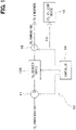
FIG. 1 is a diagram illustrating a carbon dioxide recovery system of the first embodiment. -
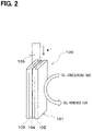
FIG. 2 is a diagram illustrating a CO2 recovery device. -
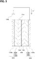
FIG. 3 is a cross-sectional view of an electrochemical cell. -
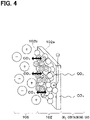
FIG. 4 is a diagram illustrating a CO2 adsorption state at a working electrode. -
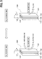
FIG. 5 is a diagram for explaining an operation of the CO2 recovery device in a CO2 recovery mode and a CO2 discharge mode. -
FIG. 6 is a diagram for explaining CO2 adsorption by a CO2 adsorbent of the first embodiment. -
FIG. 7 is a diagram for explaining CO2 desorption by the CO2 adsorbent of the first embodiment. -
FIG. 8 is a diagram for explaining CO2 adsorption by a CO2 adsorbent of the second embodiment. -
FIG. 9 is a diagram for explaining CO2 adsorption by a CO2 adsorbent of the third embodiment. -
FIG. 10 is a table illustrating current efficiencies of CO2 adsorbents in examples and comparative examples. - Hereinafter, the first embodiment of the present disclosure will be described with reference to the drawings. As shown in
FIG. 1 , a carbondioxide recovery system 10 of the present embodiment includes acompressor 11, a CO2 recovery device 100, apassage switching valve 12, a CO2 utilizing device 13, and acontroller 14. - The
compressor 11 pumps CO2 containing gas to the CO2 recovery device 100. The CO2 containing gas is mixed gas containing CO2 and gas other than CO2, and for example, the atmosphere or exhaust gas of an internal combustion engine can be used as the CO2 containing gas. - The CO2 recovery device 100 is a device that separates and recovers CO2 from the CO2 containing gas. The CO2 recovery device 100 discharges CO2 removed gas that is residual gas after CO2 is recovered from the CO2 containing gas, or CO2 recovered from the CO2 containing gas. The configuration of the CO2 recovery device 100 will be described in detail later.
- The
passage switching valve 12 is a three-way valve that switches a passage for discharged gas from the CO2 recovery device 100. Thepassage switching valve 12 switches an outlet of the passage for the discharged gas toward the atmosphere when the CO2 removed gas is discharged from the CO2 recovery device 100, and the outlet of the passage of the discharged gas toward the CO2 utilizing device 13 when CO2 is discharged from the CO2 recovery device 100. - The CO2 utilizing device 13 is a device that utilizes CO2. The CO2 utilizing device 13 may be a storage tank for storing CO2 or a conversion device for converting CO2 into fuel. As the conversion device, a device that converts CO2 into a hydrocarbon fuel such as methane can be used. The hydrocarbon fuel may be gaseous fuel at normal temperature and pressure, or may be liquid fuel at normal temperature and pressure.
- The
controller 14 is configured of a well-known microcomputer including a CPU, a ROM, a RAM and the like, and peripheral circuits thereof. Thecontroller 14 performs various calculations and processes based on control programs stored in the ROM, and controls actuations of the various devices connected to the output side. Thecontroller 14 of the present embodiment performs an operation control of thecompressor 11, an operation control of the CO2 recovery device 100, a passage switching control of thepassage switching valve 12 and the like. - Next, the CO2 recovery device 100 will be described with reference to
FIG. 2 . As shown inFIG. 2 , the CO2 recovery device 100 includes an electric field adsorption/desorptionelectrochemical cell 101 configured to adsorb and desorb CO2 via an electrochemical reaction. Theelectrochemical cell 101 has a workingelectrode 102, acounter electrode 103 and aninsulating layer 104. In the example shown inFIG. 2 , the workingelectrode 102, thecounter electrode 103 and theinsulating layer 104 are each formed in a plate shape. InFIG. 2 , the workingelectrode 102, thecounter electrode 103 and theinsulating layer 104 are illustrated to have distances between them, but actually, these components are arranged to be in contact with each other. - The
electrochemical cell 101 may be housed in a container (not shown). The container may define a gas inlet for introducing the CO2 containing gas into the container and a gas outlet for discharging the CO2 removed gas and CO2 out of the container. - The CO2 recovery device 100 is configured to adsorb and desorb CO2 via an electrochemical reaction of the
electrochemical cell 101, thereby separating and recovering CO2 from the CO2 containing gas. The CO2 recovery device 100 includes apower supply 105 that applies a predetermined voltage to the workingelectrode 102 and thecounter electrode 103, and can change the potential difference between the workingelectrode 102 and thecounter electrode 103. The workingelectrode 102 is a negative electrode, and thecounter electrode 103 is a positive electrode. - The
electrochemical cell 101 can be switched between a CO2 recovery mode in which CO2 is recovered at the workingelectrode 102 and a CO2 discharge mode in which CO2 is discharged from the workingelectrode 102 by changing the potential difference between the workingelectrode 102 and thecounter electrode 103. The CO2 recovery mode is a charging mode for charging theelectrochemical cell 101, and the CO2 discharge mode is a discharging mode for discharging theelectrochemical cell 101. - In the CO2 recovery mode, a first voltage V1 is applied between the working
electrode 102 and thecounter electrode 103, and electrons flows from thecounter electrode 103 to the workingelectrode 102. At the first voltage V1, the counter electrode potential is greater than the working electrode potential. The first voltage V1 may fall within the range between 0.5 V and 2.0 V. - In the CO2 discharge mode, a second voltage V2 is applied between the working
electrode 102 and thecounter electrode 103, and electrons flows from the workingelectrode 102 to thecounter electrode 103. The second voltage V2 is different from the first voltage V1. The second voltage V2 is a voltage lower than the first voltage V1, and the magnitude relationship between the working electrode potential and the counter electrode potential is not limited. That is, in the CO2 discharge mode, the counter electrode potential may be greater than, equal to or less than the working electrode potential. - As shown in
FIG. 3 , the workingelectrode 102 includes a workingelectrode substrate 102a, a CO2 adsorbent 102b, a working electrodeconductive substance 102c and a workingelectrode binder 102d. InFIG. 3 , for convenience, the CO2 adsorbent 102b, the working electrodeconductive substance 102c and the workingelectrode binder 102d are shown in a different position from a position of the workingelectrode substrate 102a. However, actually, the CO2 adsorbent 102b, the working electrodeconductive substance 102c and the workingelectrode binder 102d are disposed inside the porousworking electrode substrate 102a. - The working
electrode substrate 102a is a porous conductive material having pores through which gas containing CO2 can pass. As the workingelectrode substrate 102a, for example, a carbonaceous material or a metal material can be used. As the carbonaceous material constituting the workingelectrode substrate 102a, for example, carbon paper, carbon cloth, non-woven carbon mat, porous gas diffusion layer (GDL) and the like can be used. As the metal material constituting the workingelectrode substrate 102a, for example, a metal mesh that a metal (e.g., Al, Ni, etc.) is formed into a mesh shape can be used. - The CO2 adsorbent 102b adsorbs CO2 by receiving electrons, and desorbs the adsorbed CO2 by releasing electrons. The CO2 adsorbent 102b will be described in detail later.
- The working electrode
conductive substance 102c forms a conductive path to the CO2 adsorbent 102b. As the working electrodeconductive substance 102c, a carbon material such as carbon nanotube, carbon black and graphene can be used. In this embodiment, the CO2 adsorbent 102b and the working electrodeconductive substance 102c are mixed. - Mixing the CO2 adsorbent 102b and the working electrode
conductive substance 102c may be performed by dissolving the working electrodeconductive substance 102c in an organic solvent such as NMP (N-methylpyrrolidone) and bringing the CO2 adsorbent 102b into contact with the working electrodeconductive substance 102c dispersed in the organic solvent. The contact between the working electrodeconductive substance 102c and the CO2 adsorbent 102b may be realized by immersing the workingelectrode substrate 102a containing the CO2 adsorbent 102b in a solvent in which the working electrodeconductive substance 102c is dispersed and dip-coating the workingelectrode substrate 102a. As a result, the working electrodeconductive substance 102c and the CO2 adsorbent 102b can be uniformly in contact with each other. - The working
electrode binder 102d is provided to hold the CO2 adsorbent 102b in the workingelectrode substrate 102a. The workingelectrode binder 102d has an adhesive force and is provided between the CO2 adsorbent 102b and the workingelectrode substrate 102a. - In this embodiment, the CO2 adsorbent 102b, the working electrode
conductive substance 102c and the workingelectrode binder 102d are used in a mixed state. The CO2 adsorbent 102b, the working electrodeconductive substance 102c and the workingelectrode binder 102d are mixed, and this mixture adheres to the workingelectrode substrate 102a. - As the working
electrode binder 102d, a conductive resin can be used. As the conductive resin, an epoxy resin containing Ag or the like as a conductive filler, a fluorocarbon polymer such as polytetrafluoroethylene (PTFE) and polyvinylidene fluoride (PVDF) or the like can be used. - The working
electrode binder 102d can be brought into contact with the workingelectrode substrate 102a containing theCO2 adsorbent 102b by using an organic solvent similarly to the working electrodeconductive substance 102c. - Alternatively, the raw material of the working
electrode binder 102d and theCO2 adsorbent 102b may be dispersed and mixed using a homogenizer or the like, and then the mixture may be pressure-bonded to the workingelectrode substrate 102a or spray-coated on the workingelectrode substrate 102a. - The
counter electrode 103 has a similar configuration to the workingelectrode 102, and includes acounter electrode substrate 103a, an electrically activeauxiliary material 103b, a counter electrodeconductive substance 103c and acounter electrode binder 103d. - The electrically active
auxiliary material 103b is an auxiliary electrically active species that transfers electrons to and from the CO2 adsorbent 102b. As the electrically activeauxiliary material 103b, for example, a metal complex that can transfer electrons by changing the valence of the metal ion can be used. Examples of such metal complex include cyclopentadienyl metal complexes such as ferrocene, nickelocene and cobaltocene, and porphyrin metal complexes. These metal complexes may be a polymer or a monomer. - Further, as the electrically active
auxiliary material 103b, an organic compound such as phenothiazine, an inorganic compound such as RuO2, MnO2 and MoS2, and a carbon material such as carbon black and activated carbon can also be also used. - In this embodiment, polyvinyl ferrocene shown below is used as the electrically active
auxiliary material 103b. Ferrocene transfers electrons by changing the valence of Fe into divalent or trivalent.

- The insulating
layer 104 is arranged between the workingelectrode 102 and thecounter electrode 103, and separates the workingelectrode 102 and thecounter electrode 103 from each other. The insulatinglayer 104 is an insulating ion permeable membrane that prevents physical contact between the workingelectrode 102 and thecounter electrode 103 to suppress an electrical short circuit and that allows ions to permeate therethrough. - As the insulating
layer 104, a separator or a gas layer such as air can be used. In this embodiment, a porous separator is used as the insulatinglayer 104. As the material of the separator, a cellulose membrane, a polymer, a composite material of a polymer and a ceramic, or the like can be used. - An
electrolyte material 106 having ionic conductivity is provided between the workingelectrode 102 and thecounter electrode 103. Theelectrolyte material 106 is provided between the workingelectrode 102 and thecounter electrode 103 via the insulatinglayer 104. Theelectrolyte material 106 covers the workingelectrode 102, thecounter electrode 103 and the insulatinglayer 104. - The
electrolyte material 106 is in contact with the CO2 adsorbent 102b. Ions contained in theelectrolyte material 106 promote electron attraction of the CO2 adsorbent 102b when the CO2 adsorbent 102b binds to CO2. The ions contained in theelectrolyte material 106 do not directly react with a CO2 adsorption site of the CO2 adsorbent 102b that adsorbs CO2. - As the
electrolyte material 106, an ionic liquid, a solid electrolyte or the like can be used. An ionic liquid is a salt of a liquid having non-volatility under normal temperature and pressure. When an ionic liquid is used as theelectrolyte material 106, the ionic liquid may be gelled to prevent elution of the ionic liquid from theelectrochemical cell 101. When a solid electrolyte is used as theelectrolyte material 106, it is desirable to use an ionomer made of a polymer electrolyte or the like to increase a contact area with the CO2 adsorbent 102b. - Examples of the ionic liquid include 1-ethyl-3-methylimidazolium bis(trifluoromethanesulfonyl)imide ([EMIM][Tf2N]), 1-butyl-3-methylimidazolium bis(trifluoromethanesulfonyl)imide ([BMIM][Tf2N]), 1-butyl-3-methylimidazolium tetrafluoroborate ([BMIM][BF4]), 1-ethyl-1-propylpyrrolidinium bis(trifluoromethylsulfonyl)imide, N,N,N-trimethyl-N-propylammonium bis(trifluoromethanesulfonyl)imide, 1-ethyl-3-methylimidazolium tetrafluoroborate, 1-butyl-1-methylpyrrolidinium bis(trifluoromethanesulfonyl)imide, etc.
- Alternatively, H2SO4, Na2SO4, KOH or the like can be used as the
electrolyte material 106. - Here, the CO2 adsorbent 102b of the present embodiment will be described. The CO2 adsorbent 102b is a material whose chemical skeleton does not change when adsorbing CO2. In this embodiment, the CO2 adsorbent 102b is a material that can transfer electrons without changing its chemical skeleton when a negative potential is applied to the counter electrode. The CO2 adsorbent 102b is a material that allows electric charge to be delocalized in the entire material without concentrating on a specific element in its chemical structure when receiving electrons from the
counter electrode 103. - When the first voltage V1 is applied between the working
electrode 102 and thecounter electrode 103, electrons flow from thecounter electrode 103 to the workingelectrode 102, and the CO2 adsorbent 102b takes in the electrons and adsorbs CO2 by the Coulomb force of the electrons. When the second voltage V2 is applied between the workingelectrode 102 and thecounter electrode 103, electrons flow from the workingelectrode 102 to thecounter electrode 103, and the CO2 adsorbent 102b discharges the electrons and desorbs CO2. - When the CO2 adsorbent 102b adsorbs CO2, the electrons taken in by the CO2 adsorbent 102b and the ions contained in the
electrolyte material 106 form an electric double layer. By forming the electric double layer in adsorbing CO2 as described above, electrons can be stably retained on the surface of the CO2 adsorbent 102b. Therefore, it is possible to adsorb CO2 diffused in the vicinity of the surface of the CO2 adsorbent 102b and reaching the surface of the CO2 adsorbent 102b by the Coulomb force of the electrons. - The CO2 adsorbent 102b of the present embodiment has the CO2 adsorption site that takes in electrons when the first voltage V1 is applied between the working
electrode 102 and thecounter electrode 103 and that discharges the electrons when the second voltage V2 is applied between the workingelectrode 102 and thecounter electrode 103. Since the CO2 adsorbent 102b has the CO2 adsorption site capable of taking in electrons in this way, electric capacity of the electric double layer can be increased. - As shown in
FIG. 4 , the CO2 adsorbent 102b of the present embodiment adsorbs CO2 contained in the CO2 containing gas. InFIG. 4 , illustrations of the working electrodeconductive substance 102c and the workingelectrode binder 102d are omitted. - When the CO2 adsorbent 102b of the present embodiment takes in electrons, the electrons evenly spread over a plurality of elements included in the CO2 adsorption site. Thus, the electrons are not locally located in a specific element in the CO2 adsorption site. Further, as described above, since the CO2 adsorbent 102b takes in electrons and adsorbs CO2 by the Coulomb force of the electrons, a bonding that shares an electron orbit between the CO2 adsorbent 102b and CO2 is not generated when CO2 is adsorbed. That is, the CO2 adsorbent 102b does not adsorb CO2 through a chemical bond with a specific site where the electric charge is localized, but adsorbs CO2 by the Coulomb force of delocalized electrons that evenly spread over the plurality of elements.
- By taking electrons into the CO2 adsorption site contained in the CO2 adsorbent 102b, an electric double layer can be formed between the CO2 adsorption site having an electron bias and the ions contained in the
electrolyte material 106, and the electric capacity of the electric double layer can be further increased. In the CO2 adsorbent 102b, the electrons are delocalized in the CO2 adsorption site, so that the formation of the electric double layer with the ions of theelectrolyte material 106 and the CO2 adsorption by the Coulomb force of the electrons can be alternately switched at high speed. Therefore, it is possible to achieve both an increase in the electric capacity of the electric double layer and an increase in the CO2 adsorption force. - The CO2 adsorbent 102b may be any material that can transfer electrons without changing the structure of its chemical skeleton. The CO2 adsorbent 102b is a material that can receive an electric charge when a potential more negative than a natural potential is applied to the CO2 adsorbent 102b. The CO2 adsorbent 102b does not change its chemical skeleton when transferring electrons, and the electric charge is not concentrated on a specific element of the CO2 adsorbent 102b.
- In this embodiment, an organic compound is used as the CO2 adsorbent 102b. As the organic compound, for example, an aromatic compound can be used. It is desirable that the aromatic compound contains at least of N and S in the aromatic ring. N and S are elements having high electronegativity. In organic compounds, these elements having high electronegativity serve as the CO2 adsorption site.
- As the organic compound, for example, at least one of benzothiadiazole, polyvinylbenzothiadiazole and polydiazaphthalimide can be used.
- Benzothiadiazole has the following structure, and N and S contained in the aromatic ring serve as the CO2 adsorption site. When benzothiadiazole receives an electron, the electron evenly spreads over N and S, and the electron is delocalized.


- Polydiazaphthalimide has the following structure, and N contained in the aromatic ring serves as the CO2 adsorption site. When polydiazaphthalimide receives an electron, the electron evenly spreads over N, and the electron is delocalized.

- Next, the operation of the carbon
dioxide recovery system 10 of the present embodiment will be described with reference toFIGS. 5 ,6 and7 .FIGS. 6 and7 illustrate an example in which benzothiadiazole is used as the CO2 adsorbent 102b. - As shown in
FIG. 5 , the carbondioxide recovery system 10 operates by alternately switching between the CO2 recovery mode and the CO2 discharge mode. The operation of the carbondioxide recovery system 10 is controlled by thecontroller 14. - At first, the CO2 recovery mode will be described. In the CO2 recovery mode, the
compressor 11 operates to supply CO2 containing gas to the CO2 recovery device 100. In the CO2 recovery device 100, the voltage applied between the workingelectrode 102 and thecounter electrode 103 is set to the first voltage V1. As a result, electron donation of the electrically activeauxiliary material 103b of thecounter electrode 103 and electron attraction of the CO2 adsorbent 102b of the workingelectrode 102 occur at the same time. The electrically activeauxiliary material 103b of thecounter electrode 103 discharges electrons to be oxidized, and the electrons are supplied from thecounter electrode 103 to the workingelectrode 102. - As shown in
FIG. 6 , the electrons flowing to the workingelectrode 102 move to the CO2 adsorbent 102b via the working electrodeconductive substance 102c. The CO2 adsorbent 102b made of an organic compound receives electrons to be reduced. When the electrons are taken into the CO2 adsorption site of the CO2 adsorbent 102b, an electric double layer is formed between the CO2 adsorption site having an electron bias andcation 106a of theelectrolyte material 106. - As shown below, the CO2 adsorbent 102b made of the organic compound is strongly polarized by receiving electrons in the CO2 adsorption site. The part of benzothiadiazole surrounded by the broken line shows the bias of the negative charge.

- C contained in CO2 is δ+, and CO2 is attracted to the CO2 adsorption site of the CO2 adsorbent 102b by electrostatic interaction. As a result, CO2 is adsorbed on the CO2 adsorbent 102b, and the CO2 recovery device 100 can recover CO2 from CO2 containing gas.
- After CO2 is recovered by the CO2 recovery device 100, the CO2 removed gas is discharged from the CO2 recovery device 100. The
passage switching valve 12 switches the outlet of the gas passage toward the atmosphere, and the CO2 removed gas from the CO2 recovery device 100 is discharged to the atmosphere. - Next, the CO2 discharge mode will be described. In the CO2 discharge mode, the
compressor 11 is stopped and the supply of the CO2 containing gas to the CO2 recovery device 100 is stopped. - As shown in
FIG. 5 , in the CO2 recovery device 100, the voltage applied between the workingelectrode 102 and thecounter electrode 103 is set to the second voltage V2. As a result, electron donation of the CO2 adsorbent 102b of the workingelectrode 102 and electron attraction of the electrically activeauxiliary material 103b of thecounter electrode 103 occur at the same time. The electrically activeauxiliary material 103b of thecounter electrode 103 receives electrons to be reduced. - As shown in
FIG. 7 , the CO2 adsorbent 102b discharges electrons. By discharging the electrons, the CO2 adsorbent 102b desorbs CO2 adsorbed by electrostatic interaction. - The CO2 from the CO2 adsorbent 102b is discharged from the CO2 recovery device 100. The
passage switching valve 12 switches the outlet of the gas passage toward the CO2 utilizing device 13, and the CO2 discharged from the CO2 recovery device 100 is supplied to the CO2 utilizing device 13. - According to the present embodiment described above, as the CO2 adsorbent 102b of the working
electrode 102, a material that can transfer electrons without changing the structure of its chemical skeleton and in which the electric charge is delocalized is used. When the first voltage is applied between the workingelectrode 102 and thecounter electrode 103, electrons flow from thecounter electrode 103 to the workingelectrode 102, and the CO2 adsorbent takes in the electrons and adsorbs CO2 by the Coulomb force of the electrons without bonding to CO2 by sharing an electron orbit with CO2. When the second voltage is applied between the workingelectrode 102 and thecounter electrode 103, electrons flow from the workingelectrode 102 to thecounter electrode 103, and the CO2 adsorbent discharges the electrons and desorbs CO2. - Since the CO2 adsorbent 102b of the present embodiment adsorbs CO2 by the Coulomb force of delocalized electrons, CO2 can be discharged more easily compared to a material adsorbing CO2 through a chemical bond with a specific element (i.e., through a bond sharing an electron orbit with CO2). Therefore, according to the CO2 adsorbent 102b of the present embodiment, it is possible to suppress decrease in the CO2 adsorption capacity and decrease in the CO2 recovery efficiency.
- Further, in the carbon dioxide recovery system of the present embodiment, when the CO2 adsorbent adsorbs CO2, the electrons taken in by the CO2 adsorbent and the ions contained in the
electrolyte material 106 form an electric double layer. As a result, the electrons can be stably retained on the surface of the CO2 adsorbent 102b, and the CO2 diffused in the vicinity of the surface of the CO2 adsorbent 102b and reaching the surface of the CO2 adsorbent 102b can be adsorbed by the Coulomb force of the electrons. - Further, the CO2 adsorbent 102b of the present embodiment has the CO2 adsorption site that takes in electrons when the first voltage V1 is applied between the working
electrode 102 and thecounter electrode 103 and that discharges the electrons when the second voltage V2 is applied between the workingelectrode 102 and thecounter electrode 103. This makes it possible to increase the electric capacity of the electric double layer formed by the electrons taken in by the CO2 adsorbent and the ions contained in theelectrolyte material 106. - When the CO2 adsorbent 102b takes in electrons, the electrons evenly spreads over a plurality of elements contained in the CO2 adsorption site, and the electrons are not localized in the specific element. Therefore, in the CO2 adsorbent 102b, the electric double layer formation and the CO2 adsorption can be alternately switched at high speed, and both increase in the electric capacity of the electric double layer and increase in the CO2 adsorption force can be achieved at the same time.
- Next, the second embodiment of the present disclosure will be described. Hereinafter, only portions different from the first embodiment will be described.
- In the second embodiment, an inorganic compound is used as the CO2 adsorbent 102b. When an inorganic compound is used as the CO2 adsorbent 102b, the inorganic compound can be commonly used as the CO2 adsorbent 102b and the working electrode
conductive substance 102c. - The inorganic compound used as the CO2 adsorbent 102b is a material that can transfer electrons by changing the valence of the contained metal element. The inorganic compound may be at least one of an inorganic oxide, an inorganic nitride, an inorganic chalcogenide-based material, and the like. Examples of the inorganic chalcogenide-based material include sulfide, selenide and telluride.
- It is desirable that the inorganic compound contains a main group element that has high electronegativity and that can interact with CO2. It is desirable that the inorganic compound contains at least one element of O, N, S, Se and Te. In the inorganic compound, these elements having high electronegativity serve as the CO2 adsorption site.
- As the inorganic oxide, for example, RuO2 or MnO2 can be used. The inorganic chalcogenide-based material is a compound including a metal element and S, Se or Te, and for example, MoS2 can be used.
-
FIG. 8 illustrates CO2 adsorption when an inorganic compound is used as the CO2 adsorbent 102b.FIG. 8 illustrates an example in which RuO2 is used as the CO2 adsorbent 102b, and the CO2 adsorbent 102b also serves as the working electrodeconductive substance 102c. - As shown in
FIG. 8 , when electrons flow from thecounter electrode 103 to the workingelectrode 102, a part of the CO2 adsorbent 102b receives electrons to be reduced through the redox reaction. InFIG. 8 , the reduced CO2 adsorbent 102b is shown in diagonal lines. - The CO2 adsorbent 102b made of an inorganic compound takes in electrons into the CO2 adsorption site made of a main group element (O in the case of RuO2), and forms an electric double layer between the CO2 adsorption site and the
cations 106a of theelectrolyte material 106. - The CO2 adsorbent 102b made of an inorganic compound adsorbs CO2 on the CO2 adsorption site (O in the case of RuO2) by electrostatic interaction.
- As shown in the reaction formula below, in a part of RuO2, the valence of Ru changes from tetravalent to trivalent by receiving electrons, and the valence of Ru changes from trivalent to tetravalent by discharging the electrons.
Ru(IV)O2 + x[EMIM]+ + xe- ←→ Ru(IV)Ru(III)1-xO2[EMIM]x +
[EMIM]+ is acation 106a of an ionic liquid used as theelectrolyte material 106. - In the second embodiment described above, an inorganic compound is used as the CO2 adsorbent 102b. Also in the configuration of the second embodiment, the same or similar advantages as those of the first embodiment can be obtained, and it is possible to suppress decrease in the CO2 recovery efficiency of the CO2 adsorbent 102b.
- Next, the third embodiment of the present disclosure will be described. Hereinafter, only portions different from the above embodiments will be described.
- In the third embodiment, a porous material is used as the CO2 adsorbent 102b. In the third embodiment, a carbon material is used as the porous material constituting the CO2 adsorbent 102b.
- The carbon material has a porous body and conductivity. When a carbon material is used as the CO2 adsorbent 102b, the carbon material is commonly used as the CO2 adsorbent 102b and the working electrode
conductive substance 102c. As the carbon material, for example, at least one of graphite, carbon black, carbon nanotube, graphene, and activated carbon can be used. -
FIG. 9 illustrates CO2 adsorption when a carbon material is used as the CO2 adsorbent 102b. In the example shown inFIG. 9 , the CO2 adsorbent 102b also serves as the working electrodeconductive substance 102c. - As shown in
FIG. 9 , when electrons flow from thecounter electrode 103 to the workingelectrode 102, the electrons can conduct to the surface of the CO2 adsorbent 102b. The CO2 adsorbent 102b takes in electrons to form an electric double layer with thecations 106a of theelectrolyte material 106. - Since the CO2 adsorbent 102 made of a carbon material has a large contact area with the
electrolyte material 106, the electric capacity of the electric double layer increases. Therefore, the amount of CO2 adsorbed by the CO2 adsorbent 102 and the adsorption efficiency can be increased. - In the third embodiment described above, a carbon material is used as the CO2 adsorbent 102b. Also in the configuration of the third embodiment, the same or similar advantages as those of the first embodiment can be obtained, and it is possible to suppress decrease in the CO2 recovery efficiency of the CO2 adsorbent 102b.
- Next, the fourth embodiment of the present disclosure will be described. Hereinafter, only portions different from the above embodiments will be described.
- In the fourth embodiment, a porous material is used as the CO2 adsorbent 102b. In the fourth embodiment, an organometallic complex is used as the porous material constituting the CO2 adsorbent 102b. When an organometallic complex is used as the CO2 adsorbent 102b, it is desirable to mix the working electrode
conductive substance 102c made of a carbon material with the organometallic complex. - The organometallic complex is a metal-organic framework (MOF) having a porous structure in which an organic ligand is coordinated and bonded to a metal ion. As the organometallic complex, for example, at least one of CAU-8, HKUST-1 (MOF-199), MOF-801, and MOF-867 can be used.
- CAU-8 is an organometallic structure containing Al ion as a metal ion and benzophenone dicarboxylate as an organic ligand. HKUST-1 (MOF-199) is an organometallic structure containing Cu ion as a metal ion and 1,3,5-benzenetricarboxylate as an organic ligand. MOF-801 and MOF-867 are organometallic structures containing Zr ions as metal ions.
- The CO2 adsorbent 102b takes in electrons to form an electric double layer with the
cations 106a of theelectrolyte material 106. Since the CO2 adsorbent 102 made of an organometallic complex has a large contact area with theelectrolyte material 106, the electric capacity of the electric double layer increases. Therefore, the amount of CO2 adsorbed by the CO2 adsorbent 102 and the adsorption efficiency can be increased. - In the fourth embodiment described above, an organometallic complex is used as the CO2 adsorbent 102b. Also in the configuration of the fourth embodiment, the same or similar advantages as those of the first embodiment can be obtained, and it is possible to suppress decrease in the CO2 recovery efficiency of the CO2 adsorbent 102b.
- Next, examples of the above embodiments will be described with reference to
FIG. 10 . The current efficiency when CO2 is adsorbed on the CO2 adsorbent 102b will be described with reference to the examples and comparative examples. The current efficiency indicates a ratio of the number of CO2 molecules adsorbed on the CO2 adsorbent 102b to the number of electrons flowing to the CO2 adsorbent 102b. - The CO2 adsorbents 102b of examples 1 to 7 were respectively benzothiadiazole (example 1), polyvinylbenzothiadiazole (example 2), carbon black (example 3), polydiazaphthalimide (example 4), RuO2 (example 5), MoS2 (example 6) and MnO2 (example 7). As the CO2 adsorbent 102b, anthraquinone was used in the comparative example 1 and fluorenone was used in the comparative example 2.
- As shown in
FIG. 10 , the current efficiency of example 1 was 93%, the current efficiency of example 2 was 95%, the current efficiency of example 3 was 96%, the current efficiency of example 4 was 93%, the current efficiency of example 5 was 102%, the current efficiency of example 6 was 92% and the current efficiency of example 7 was 105%. The current efficiency of comparative example 1 was 60% and the current efficiency of comparative example 2 was 40%. As described above, the materials of examples 1 to 7 have significantly higher current efficiencies than the materials of comparative examples 1 and 2, and the materials of examples 1 to 7 have superior CO2 adsorption capacity than the materials of comparative examples 1 and 2. - The present disclosure is not limited to the embodiments described hereinabove, and may be modified in various ways without departing from the gist of the present disclosure. Further, means disclosed in the above embodiments may be appropriately combined within a range that can be implemented.
- For example, in each of the above embodiments, as the CO2 adsorbent 102b, an organic compound, an inorganic compound, a carbon material, or an organometallic complex is used alone, but these may be used in combination as appropriate.
- Further, in each of the above embodiments, the working
electrode binder 102d is disposed for holding the CO2 adsorbent 102b on the workingelectrode substrate 102a, but the present disclosure is not limited to this. The workingelectrode binder 102d may be omitted. - A carbon dioxide recovery system is configured to separate carbon dioxide from gas containing the carbon dioxide via an electrochemical reaction and includes an electrochemical cell (101) including a working electrode (102) and a counter electrode (103). The working electrode includes a CO2 adsorbent. The CO2 adsorbent is configured to, when a first voltage is applied between the working electrode and the counter electrode, take in electrons flowing from the counter electrode to the working electrode and adsorb the carbon dioxide by a Coulomb force of the electrons without bonding to the carbon dioxide by sharing an electron orbital with the carbon dioxide. The CO2 adsorbent is configured to, when a second voltage different from the first voltage is applied between the working electrode and the counter electrode, discharge the electrons from the working electrode to the counter electrode and desorb the carbon dioxide.
Claims (13)
- A carbon dioxide recovery system that separates carbon dioxide from gas containing the carbon dioxide via an electrochemical reaction, the carbon dioxide recovery system comprising:an electrochemical cell (101) including a working electrode (102) and a counter electrode (103), the working electrode including a CO2 adsorbent, whereinthe CO2 adsorbent is configured to:when a first voltage is applied between the working electrode and the counter electrode:take in electrons flowing from the counter electrode to the working electrode; andadsorb the carbon dioxide by a Coulomb force of the electrons without bonding to the carbon dioxide by sharing an electron orbital with the carbon dioxide; andwhen a second voltage different from the first voltage is applied between the working electrode and the counter electrode:discharge the electrons from the working electrode to the counter electrode; anddesorb the carbon dioxide.
- The carbon dioxide recovery system according to claim 1, whereinthe electrochemical cell includes:an insulating layer (104) disposed between the working electrode and the counter electrode; andan electrolyte material (106) covering the working electrode, the counter electrode and the insulating layer, andthe electrons taken in by the CO2 adsorbent and ions contained in the electrolyte material form an electrical double layer when the CO2 adsorbent adsorbs the carbon dioxide.
- The carbon dioxide recovery system according to claim 1 or 2, wherein
the CO2 adsorbent includes a CO2 adsorption site that takes in the electrons when the first voltage is applied between the working electrode and the counter electrode and that discharges the electrons when the second voltage is applied between the working electrode and the counter electrode. - The carbon dioxide recovery system according to claim 3, whereinthe CO2 adsorption site includes a plurality of elements, andthe electrons evenly spread over the plurality of elements when the CO2 adsorbent takes in the electrons.
- The carbon dioxide recovery system according to any one of claims 1 to 4, whereinthe CO2 adsorbent is an organic compound, andthe organic compound is an aromatic compound having at least one of a nitrogen atom or a sulfur atom in an aromatic ring.
- The carbon dioxide recovery system according to claim 5, wherein
the organic compound includes at least one of benzothiadiazole, polyvinyl benzothiadiazole or polydiaza phthalimide. - The carbon dioxide recovery system according to any one of claims 1 to 4, whereinthe CO2 adsorbent is an inorganic compound including a metal, andthe inorganic compound is configured to take in and discharge the electrons through a valence change of the metal.
- The carbon dioxide recovery system according to claim 7, wherein
the inorganic compound includes at least one of an inorganic oxide, an inorganic nitride or an inorganic chalcogenide-based material. - The carbon dioxide recovery system according to claim 7 or 8, wherein the inorganic compound includes at least one of RuO2, MbO2 or MoS2.
- The carbon dioxide recovery system according to claim 1 or 2, wherein the CO2 adsorbent is a porous material.
- The carbon dioxide recovery system according to claim 10, wherein the porous material is a carbon material.
- The carbon dioxide recovery system according to claim 11, wherein
the carbon material is at least one of a carbon black, a carbon nanotube, a graphene or an activated carbon. - The carbon dioxide recovery system according to claim 10, wherein the porous material is an organometallic complex.
Applications Claiming Priority (1)
| Application Number | Priority Date | Filing Date | Title |
|---|---|---|---|
| JP2021084307A JP7694141B2 (en) | 2021-05-19 | 2021-05-19 | Carbon Dioxide Capture System |
Publications (1)
| Publication Number | Publication Date |
|---|---|
| EP4091701A1 true EP4091701A1 (en) | 2022-11-23 |
Family
ID=81748597
Family Applications (1)
| Application Number | Title | Priority Date | Filing Date |
|---|---|---|---|
| EP22173715.8A Pending EP4091701A1 (en) | 2021-05-19 | 2022-05-17 | Carbon dioxide recovery system |
Country Status (4)
| Country | Link |
|---|---|
| US (2) | US20220387930A1 (en) |
| EP (1) | EP4091701A1 (en) |
| JP (1) | JP7694141B2 (en) |
| CN (1) | CN115364635A (en) |
Cited By (1)
| Publication number | Priority date | Publication date | Assignee | Title |
|---|---|---|---|---|
| KR20250139447A (en) * | 2024-03-15 | 2025-09-23 | 울산과학대학교 산학협력단 | Carbon Mat Manufacturing Method |
Families Citing this family (8)
| Publication number | Priority date | Publication date | Assignee | Title |
|---|---|---|---|---|
| US20230405511A1 (en) | 2021-07-30 | 2023-12-21 | Noya, Inc. | Systems and Methods for Removing Carbon Dioxide from a Fluid |
| JP7806606B2 (en) | 2022-04-25 | 2026-01-27 | 株式会社デンソー | Carbon dioxide capture system |
| JP2023176214A (en) | 2022-05-31 | 2023-12-13 | 株式会社Soken | Gas recovery system and electrode membrane manufacturing method |
| EP4558241A2 (en) * | 2022-07-22 | 2025-05-28 | Noya, Inc. | Systems and methods for removing carbon dioxide from a fluid |
| US20240322202A1 (en) | 2023-03-23 | 2024-09-26 | Denso Corporation | Electrochemical cell |
| US12523346B2 (en) * | 2023-05-26 | 2026-01-13 | Caterpillar Inc. | System and method for transportation of captured carbon |
| WO2025057932A1 (en) * | 2023-09-12 | 2025-03-20 | 京セラ株式会社 | Electrochemical cell unit |
| DE102024201977A1 (en) * | 2024-03-04 | 2025-09-04 | Robert Bosch Gesellschaft mit beschränkter Haftung | Gas deposition cell with proton-based charge compensation |
Citations (5)
| Publication number | Priority date | Publication date | Assignee | Title |
|---|---|---|---|---|
| US20040018936A1 (en) * | 2002-03-06 | 2004-01-29 | Hammel Charles F. | Regeneration, pretreatment and precipitation of oxides of manganese |
| JP2008528285A (en) | 2005-02-03 | 2008-07-31 | サーマル エナジー システムズ リミテッド | Gas separation and compression equipment |
| US20110243820A1 (en) * | 2010-04-02 | 2011-10-06 | Mcgrail B Peter | Methods for Associating or Dissociating Guest Materials with a Metal Organic Framework, Systems for Associating or Dissociating Guest Materials Within a Series of Metal Organic Frameworks, and Gas Separation Assemblies |
| US20170113182A1 (en) * | 2015-10-27 | 2017-04-27 | Massachusetts Institute Of Technology | Electrochemical process for gas separation |
| US20180085703A1 (en) * | 2016-09-23 | 2018-03-29 | Lehigh University | Gas separation apparatus and methods using same |
Family Cites Families (8)
| Publication number | Priority date | Publication date | Assignee | Title |
|---|---|---|---|---|
| CN101841051A (en) * | 2010-03-24 | 2010-09-22 | 苏州大学 | New CO2-based energy storage method and device |
| US20140166499A1 (en) * | 2011-04-20 | 2014-06-19 | Lehigh University | Supercapacitive swing adsorption |
| JP5604588B2 (en) * | 2011-04-21 | 2014-10-08 | パナソニック株式会社 | Carbon dioxide adsorption and release device |
| EP2727882A4 (en) * | 2011-05-31 | 2015-05-27 | Japan Science & Tech Agency | CARBON DIOXIDE ENRICHMENT DEVICE |
| JP2015077594A (en) * | 2013-09-12 | 2015-04-23 | パナソニックIpマネジメント株式会社 | Method for adsorbing carbon dioxide on porous metal organic framework material, method for cooling porous metal organic framework material, method for obtaining aldehyde using porous metal organic framework material, and heating porous metal organic framework material Method |
| GB201705646D0 (en) * | 2017-04-07 | 2017-05-24 | Arvia Tech Ltd | Apparatus and methods for aqueous organic waste treatment |
| JP6940756B2 (en) * | 2017-06-29 | 2021-09-29 | 富士通株式会社 | Carbon dioxide reduction electrode, its manufacturing method, and carbon dioxide reduction device |
| JP7453651B2 (en) * | 2020-10-30 | 2024-03-21 | 株式会社デンソー | Electrochemical cells and carbon dioxide capture systems |
-
2021
- 2021-05-19 JP JP2021084307A patent/JP7694141B2/en active Active
-
2022
- 2022-05-13 CN CN202210519184.7A patent/CN115364635A/en active Pending
- 2022-05-16 US US17/744,837 patent/US20220387930A1/en not_active Abandoned
- 2022-05-17 EP EP22173715.8A patent/EP4091701A1/en active Pending
-
2025
- 2025-03-14 US US19/079,904 patent/US20250214033A1/en active Pending
Patent Citations (5)
| Publication number | Priority date | Publication date | Assignee | Title |
|---|---|---|---|---|
| US20040018936A1 (en) * | 2002-03-06 | 2004-01-29 | Hammel Charles F. | Regeneration, pretreatment and precipitation of oxides of manganese |
| JP2008528285A (en) | 2005-02-03 | 2008-07-31 | サーマル エナジー システムズ リミテッド | Gas separation and compression equipment |
| US20110243820A1 (en) * | 2010-04-02 | 2011-10-06 | Mcgrail B Peter | Methods for Associating or Dissociating Guest Materials with a Metal Organic Framework, Systems for Associating or Dissociating Guest Materials Within a Series of Metal Organic Frameworks, and Gas Separation Assemblies |
| US20170113182A1 (en) * | 2015-10-27 | 2017-04-27 | Massachusetts Institute Of Technology | Electrochemical process for gas separation |
| US20180085703A1 (en) * | 2016-09-23 | 2018-03-29 | Lehigh University | Gas separation apparatus and methods using same |
Non-Patent Citations (1)
| Title |
|---|
| SONG CHENGLING ET AL: "Enhanced CO 2 sorption and selectivity by functionalization of a NbO-type metal-organic framework with polarized benzothiadiazole moieties", CHEMICAL COMMUNICATIONS, vol. 50, no. 81, 20 August 2014 (2014-08-20), UK, pages 12105 - 12108, XP055963470, ISSN: 1359-7345, DOI: 10.1039/C4CC05833J * |
Cited By (1)
| Publication number | Priority date | Publication date | Assignee | Title |
|---|---|---|---|---|
| KR20250139447A (en) * | 2024-03-15 | 2025-09-23 | 울산과학대학교 산학협력단 | Carbon Mat Manufacturing Method |
Also Published As
| Publication number | Publication date |
|---|---|
| JP2022177883A (en) | 2022-12-02 |
| US20250214033A1 (en) | 2025-07-03 |
| JP7694141B2 (en) | 2025-06-18 |
| CN115364635A (en) | 2022-11-22 |
| US20220387930A1 (en) | 2022-12-08 |
Similar Documents
| Publication | Publication Date | Title |
|---|---|---|
| EP4091701A1 (en) | Carbon dioxide recovery system | |
| JP7453651B2 (en) | Electrochemical cells and carbon dioxide capture systems | |
| EP3988201A1 (en) | Carbon dioxide recovery system and working electrode | |
| US20240149215A1 (en) | Carbon dioxide recovery system | |
| JP2023046605A (en) | gas recovery system | |
| US20250170516A1 (en) | Carbon dioxide recovery system | |
| US20230383429A1 (en) | Carbon dioxide recovery system | |
| US20230381715A1 (en) | Carbon dioxide recovery system | |
| US20250121322A1 (en) | Carbon dioxide recovery system | |
| US20240382900A1 (en) | Electrochemical cell | |
| US20250288952A1 (en) | Electrochemical cell and carbon dioxide recovery system | |
| US20260115656A1 (en) | Electrochemical cell | |
| US20250135395A1 (en) | Carbon dioxide recovery system | |
| US20230387425A1 (en) | Electrochemical cell, gas recovery system equipped with electrochemical cell, and method of manufacturing electrochemical cell | |
| JP2025173200A (en) | electrochemical cell | |
| US20240322202A1 (en) | Electrochemical cell | |
| JP2024008535A (en) | Electrochemical cell and its manufacturing method | |
| JP2024137687A (en) | Electrochemical Cell | |
| JP2024162107A (en) | Carbon Dioxide Capture System | |
| JP2025141783A (en) | Electrochemical cell and carbon dioxide recovery system | |
| JP2025065732A (en) | Acid Gas Recovery System |
Legal Events
| Date | Code | Title | Description |
|---|---|---|---|
| PUAI | Public reference made under article 153(3) epc to a published international application that has entered the european phase |
Free format text: ORIGINAL CODE: 0009012 |
|
| STAA | Information on the status of an ep patent application or granted ep patent |
Free format text: STATUS: THE APPLICATION HAS BEEN PUBLISHED |
|
| AK | Designated contracting states |
Kind code of ref document: A1 Designated state(s): AL AT BE BG CH CY CZ DE DK EE ES FI FR GB GR HR HU IE IS IT LI LT LU LV MC MK MT NL NO PL PT RO RS SE SI SK SM TR |
|
| STAA | Information on the status of an ep patent application or granted ep patent |
Free format text: STATUS: REQUEST FOR EXAMINATION WAS MADE |
|
| 17P | Request for examination filed |
Effective date: 20230209 |
|
| RBV | Designated contracting states (corrected) |
Designated state(s): AL AT BE BG CH CY CZ DE DK EE ES FI FR GB GR HR HU IE IS IT LI LT LU LV MC MK MT NL NO PL PT RO RS SE SI SK SM TR |