EP4091512A1 - Dust scraping device and cleaning apparatus - Google Patents
Dust scraping device and cleaning apparatus Download PDFInfo
- Publication number
- EP4091512A1 EP4091512A1 EP21217965.9A EP21217965A EP4091512A1 EP 4091512 A1 EP4091512 A1 EP 4091512A1 EP 21217965 A EP21217965 A EP 21217965A EP 4091512 A1 EP4091512 A1 EP 4091512A1
- Authority
- EP
- European Patent Office
- Prior art keywords
- dust
- dust scraping
- main body
- cyclone separation
- ring
- Prior art date
- Legal status (The legal status is an assumption and is not a legal conclusion. Google has not performed a legal analysis and makes no representation as to the accuracy of the status listed.)
- Granted
Links
Images


Classifications
-
- A—HUMAN NECESSITIES
- A47—FURNITURE; DOMESTIC ARTICLES OR APPLIANCES; COFFEE MILLS; SPICE MILLS; SUCTION CLEANERS IN GENERAL
- A47L—DOMESTIC WASHING OR CLEANING; SUCTION CLEANERS IN GENERAL
- A47L9/00—Details or accessories of suction cleaners, e.g. mechanical means for controlling the suction or for effecting pulsating action; Storing devices specially adapted to suction cleaners or parts thereof; Carrying-vehicles specially adapted for suction cleaners
- A47L9/02—Nozzles
- A47L9/06—Nozzles with fixed, e.g. adjustably fixed brushes or the like
- A47L9/0606—Nozzles with fixed, e.g. adjustably fixed brushes or the like rigidly anchored brushes, combs, lips or pads
- A47L9/0626—Rigidly anchored lips, e.g. nozzles adapted for picking up liquids
-
- A—HUMAN NECESSITIES
- A47—FURNITURE; DOMESTIC ARTICLES OR APPLIANCES; COFFEE MILLS; SPICE MILLS; SUCTION CLEANERS IN GENERAL
- A47L—DOMESTIC WASHING OR CLEANING; SUCTION CLEANERS IN GENERAL
- A47L9/00—Details or accessories of suction cleaners, e.g. mechanical means for controlling the suction or for effecting pulsating action; Storing devices specially adapted to suction cleaners or parts thereof; Carrying-vehicles specially adapted for suction cleaners
- A47L9/20—Means for cleaning filters
-
- A—HUMAN NECESSITIES
- A47—FURNITURE; DOMESTIC ARTICLES OR APPLIANCES; COFFEE MILLS; SPICE MILLS; SUCTION CLEANERS IN GENERAL
- A47L—DOMESTIC WASHING OR CLEANING; SUCTION CLEANERS IN GENERAL
- A47L5/00—Structural features of suction cleaners
- A47L5/12—Structural features of suction cleaners with power-driven air-pumps or air-compressors, e.g. driven by motor vehicle engine vacuum
- A47L5/22—Structural features of suction cleaners with power-driven air-pumps or air-compressors, e.g. driven by motor vehicle engine vacuum with rotary fans
- A47L5/24—Hand-supported suction cleaners
-
- A—HUMAN NECESSITIES
- A47—FURNITURE; DOMESTIC ARTICLES OR APPLIANCES; COFFEE MILLS; SPICE MILLS; SUCTION CLEANERS IN GENERAL
- A47L—DOMESTIC WASHING OR CLEANING; SUCTION CLEANERS IN GENERAL
- A47L9/00—Details or accessories of suction cleaners, e.g. mechanical means for controlling the suction or for effecting pulsating action; Storing devices specially adapted to suction cleaners or parts thereof; Carrying-vehicles specially adapted for suction cleaners
- A47L9/10—Filters; Dust separators; Dust removal; Automatic exchange of filters
- A47L9/12—Dry filters
- A47L9/127—Dry filters tube- or sleeve-shaped
-
- A—HUMAN NECESSITIES
- A47—FURNITURE; DOMESTIC ARTICLES OR APPLIANCES; COFFEE MILLS; SPICE MILLS; SUCTION CLEANERS IN GENERAL
- A47L—DOMESTIC WASHING OR CLEANING; SUCTION CLEANERS IN GENERAL
- A47L9/00—Details or accessories of suction cleaners, e.g. mechanical means for controlling the suction or for effecting pulsating action; Storing devices specially adapted to suction cleaners or parts thereof; Carrying-vehicles specially adapted for suction cleaners
- A47L9/10—Filters; Dust separators; Dust removal; Automatic exchange of filters
- A47L9/16—Arrangement or disposition of cyclones or other devices with centrifugal action
- A47L9/1608—Cyclonic chamber constructions
-
- A—HUMAN NECESSITIES
- A47—FURNITURE; DOMESTIC ARTICLES OR APPLIANCES; COFFEE MILLS; SPICE MILLS; SUCTION CLEANERS IN GENERAL
- A47L—DOMESTIC WASHING OR CLEANING; SUCTION CLEANERS IN GENERAL
- A47L9/00—Details or accessories of suction cleaners, e.g. mechanical means for controlling the suction or for effecting pulsating action; Storing devices specially adapted to suction cleaners or parts thereof; Carrying-vehicles specially adapted for suction cleaners
- A47L9/10—Filters; Dust separators; Dust removal; Automatic exchange of filters
- A47L9/16—Arrangement or disposition of cyclones or other devices with centrifugal action
- A47L9/1616—Multiple arrangement thereof
- A47L9/1625—Multiple arrangement thereof for series flow
-
- A—HUMAN NECESSITIES
- A47—FURNITURE; DOMESTIC ARTICLES OR APPLIANCES; COFFEE MILLS; SPICE MILLS; SUCTION CLEANERS IN GENERAL
- A47L—DOMESTIC WASHING OR CLEANING; SUCTION CLEANERS IN GENERAL
- A47L9/00—Details or accessories of suction cleaners, e.g. mechanical means for controlling the suction or for effecting pulsating action; Storing devices specially adapted to suction cleaners or parts thereof; Carrying-vehicles specially adapted for suction cleaners
- A47L9/10—Filters; Dust separators; Dust removal; Automatic exchange of filters
- A47L9/16—Arrangement or disposition of cyclones or other devices with centrifugal action
- A47L9/1616—Multiple arrangement thereof
- A47L9/1641—Multiple arrangement thereof for parallel flow
-
- A—HUMAN NECESSITIES
- A47—FURNITURE; DOMESTIC ARTICLES OR APPLIANCES; COFFEE MILLS; SPICE MILLS; SUCTION CLEANERS IN GENERAL
- A47L—DOMESTIC WASHING OR CLEANING; SUCTION CLEANERS IN GENERAL
- A47L9/00—Details or accessories of suction cleaners, e.g. mechanical means for controlling the suction or for effecting pulsating action; Storing devices specially adapted to suction cleaners or parts thereof; Carrying-vehicles specially adapted for suction cleaners
- A47L9/10—Filters; Dust separators; Dust removal; Automatic exchange of filters
- A47L9/16—Arrangement or disposition of cyclones or other devices with centrifugal action
- A47L9/1658—Construction of outlets
- A47L9/1666—Construction of outlets with filtering means
-
- A—HUMAN NECESSITIES
- A47—FURNITURE; DOMESTIC ARTICLES OR APPLIANCES; COFFEE MILLS; SPICE MILLS; SUCTION CLEANERS IN GENERAL
- A47L—DOMESTIC WASHING OR CLEANING; SUCTION CLEANERS IN GENERAL
- A47L9/00—Details or accessories of suction cleaners, e.g. mechanical means for controlling the suction or for effecting pulsating action; Storing devices specially adapted to suction cleaners or parts thereof; Carrying-vehicles specially adapted for suction cleaners
- A47L9/10—Filters; Dust separators; Dust removal; Automatic exchange of filters
- A47L9/16—Arrangement or disposition of cyclones or other devices with centrifugal action
- A47L9/1683—Dust collecting chambers; Dust collecting receptacles
-
- A—HUMAN NECESSITIES
- A47—FURNITURE; DOMESTIC ARTICLES OR APPLIANCES; COFFEE MILLS; SPICE MILLS; SUCTION CLEANERS IN GENERAL
- A47L—DOMESTIC WASHING OR CLEANING; SUCTION CLEANERS IN GENERAL
- A47L9/00—Details or accessories of suction cleaners, e.g. mechanical means for controlling the suction or for effecting pulsating action; Storing devices specially adapted to suction cleaners or parts thereof; Carrying-vehicles specially adapted for suction cleaners
- A47L9/10—Filters; Dust separators; Dust removal; Automatic exchange of filters
- A47L9/16—Arrangement or disposition of cyclones or other devices with centrifugal action
- A47L9/1691—Mounting or coupling means for cyclonic chamber or dust receptacles
Definitions
- the present disclosure relates to a field of cleaning apparatuses and, more particularly, to a dust scraping device and a cleaning apparatus.
- the handheld cleaning apparatus has a cyclone separation unit arranged in a dust cup.
- the dust cup is detachably coupled to a main body of the cleaning apparatus.
- dirt such as hair or debris enters the dust cup via an air inlet tube of the cleaning apparatus, and separation of dirt and air is carried out by the cyclone separation unit in the dust cup, so that the dirt is retained between the dust cup and the cyclone separation unit, and clean air is discharged out of the cleaning apparatus from an air outlet of the main body of the cleaning apparatus.
- the present disclosure provides a cleaning apparatus and a dust scraping device for a cleaning apparatus, which can solve the technical problem that hair, dust and other dirt are wound around an outer side of a cyclone separation unit in the cleaning apparatus.
- the present disclosure provides a dust scraping device for a cleaning apparatus.
- the cleaning apparatus includes a dust cup and a removable cyclone separation unit arranged in the dust cup.
- the dust scraping device includes a dust scraping member.
- the dust scraping member has a connection portion extending in a removal direction of the cyclone separation unit, and a dust scraping portion extending to an interior of the dust cup in a direction perpendicular to the removal direction and slidably abutting against the cyclone separation unit.
- the dust scraping device is mounted at the dust cup, and the dust scraping portion scrapes off at least part of debris on an outer side of the cyclone separation unit when the cyclone separation unit is removed from the dust cup.
- the dust cup has a cylindrical dust cup main body and an open portion arranged at an end of the dust cup main body;
- the dust scraping member is a cylindrical dust scraping ring, and the dust scraping ring is coaxially mounted at the open portion of the dust cup;
- the cyclone separation unit is coaxially arranged within the dust cup, and the cyclone separation unit includes a cylindrical filter screen and a cyclone separation portion located downstream of the filter screen; and the dust scraping ring scrapes off debris on an outer side of the filter screen.
- the dust scraping ring has an L-shaped radial section, the connection portion being a transverse portion of the L-shaped radial section, and the dust scraping portion being a vertical portion of the L-shaped radial section.
- the dust scraping ring includes a mounting ring and an annular dust scraping plate; an outer wall of the mounting ring is fixedly coupled to the interior of the dust cup; the annular dust scraping plate is integrally formed on a side, away from the open portion, of the mounting ring, radially extends inwards, and abuts against the filter screen; and the filter screen slides past the annular dust scraping plate and debris is scraped off when the cyclone separation unit is removed from the dust cup.
- the dust scraping device further includes: a connection base arranged coaxially with the dust scraping ring and fixed to the open portion of the dust cup; and a dust scraping ring mounting rack arranged coaxially with the dust scraping ring and in the connection base, a side, away from the open portion, of the dust scraping ring mounting rack being fixedly coupled to the mounting ring.
- the dust scraping device further includes a supporting washer arranged coaxially in the mounting ring; the supporting washer has an outer peripheral surface of the supporting washer abutting against an inner peripheral surface of the mounting ring; the supporting washer has an end abutting against the annular dust scraping plate and supports the mounting ring and the annular dust scraping plate.
- an initial position of the annular dust scraping plate is a position where an inner ring of the annular dust scraping plate abuts against a seat of the filter screen.
- an annular positioning step is formed at a junction between an inner side wall of the connection base and the dust scraping ring mounting rack and positions the cyclone separation unit; a cooperation step is formed at the cyclone separation unit and cooperates with the annular positioning step; a seal ring is arranged between the annular positioning step and the cooperation step.
- the dust scraping ring is made of a rubber material.
- the present disclosure provides a cleaning apparatus including: a gun-shaped main body; a main machine mounted on the main body; a dust cup; a removable cyclone separation unit arranged in the dust cup; and the dust scraping device according to the first aspect of the present disclosure, in which the dust cup and the main machine are arranged on the main body, and the dust scraping device is fixedly mounted at the dust cup and is coupled to the main machine by an engagement structure.
- the cleaning apparatus further includes a skirt partitioning device mounted at a bottom of the cyclone separation unit, wherein the skirt partitioning device includes an annular inner ring and an annular skirt main body.
- the skirt main body has a root coupled to the inner ring and an edge part at an end, away from the inner ring, of the skirt main body, and the edge part has a diameter greater than the root.
- a plurality of collapsing portions are formed on the skirt main body and arranged at intervals in a peripheral direction of the skirt main body, and each of the collapsing portions has a strip-shaped structure extending in a radial direction of the skirt main body.
- the collapsing portions protrude on a first side surface of the skirt main body relative to the skirt main body and are recessed on a second side surface of the skirt main body relative to the skirt main body, in a thickness direction of the skirt main body.
- a size of each collapsing portion protruding beyond the skirt main body on the first side surface of the skirt main body is gradually reduced from the root to the edge part; and/or a size of each collapsing portion recessed in the skirt main body on the second side surface of the skirt main body is gradually reduced from the root to the edge part.
- the dust scraping device has the connection portion extending in an axis of the dust cup and a dust scraping portion extending to the interior of the dust cup in a direction perpendicular to the axis of the dust cup and slidably abutting against the cyclone separation unit.
- the dust scraping device is mounted at the dust cup, and when the cyclone separation unit is removed from the dust cup, the debris on the outer side of the cyclone separation unit is scraped off by the dust scraping portion.
- the dust scraping device can scrape off hair, dust and other debris wound around the outer side of the cyclone separation unit. Meanwhile, the dust scraping device has a simple structure and excellent dust scraping effect, occupies a small space, and is less likely to interfere with other components.
- the inventors have found during research that the dust cup needs to be cleaned after being used for a period of time, and during cleaning, the dust cup is removed from the main body of the cleaning apparatus and cleaned. Moreover, after the cleaning apparatus is used for a period of time, hair and other dirt may be easily wound around an outer circumference of a filter screen in the cyclone separation unit, which makes it difficult to clean the cleaning apparatus.
- embodiments of the present disclosure provide a cleaning apparatus, including a main body 80, a main machine 60 mounted on the main body 80, a dust cup 20, and a removal cyclone separation unit 10 arranged in the dust cup 20.
- the cleaning apparatus further includes a dust scraping device used for the cleaning apparatus.
- the dust cup 20 and the main machine 60 are arranged on the main body 80, and the dust scraping device is fixedly mounted on the dust cup 20 and coupled to the main machine 60 by an engagement structure.
- the main machine 60 includes a main machine housing 61 and a blower 62 mounted in the main machine housing 61.
- a lower end surface of the main machine housing 61 extends outwards and forms a cylindrical connection end.
- Three engagement blocks 63 are integrally formed and arranged at equal intervals outside the connection end, and the engagement blocks are fitted, engaged and fixed with engagement slots 31 formed in the dust scraping device on the dust cup 20. Due to the arrangement of the engagement blocks 63 and the engagement slots 31, the dust cup 20 and the main machine 60 can be assembled or disassembled quickly and conveniently.
- the blower 62 is electrically coupled to a master control circuit within the main body 80 and is used to draw in external air.
- the dust scraping device includes a dust scraping member; and the dust scraping member has a connection portion extending in a removal direction of the cyclone separation unit 10, and a dust scraping portion extending to an interior of the dust cup 20 in a direction perpendicular to the removal direction and slidably abutting against the cyclone separation unit 10.
- the dust cup 20 has a cylindrical dust cup main body and an open portion arranged at an end of the dust cup main body; the dust scraping member is a cylindrical dust scraping ring 50; and the dust scraping ring 50 is coaxially mounted at the open portion of the dust cup 20.
- the cyclone separation unit 10 is coaxially arranged within the dust cup 20, the cyclone separation unit 10 includes a cylindrical filter screen 11 and a cyclone separation portion located downstream of the filter screen 11.
- the dust scraping ring 50 is capable of scrapping off debris on an outer side of the filter screen 11, and the debris falls into the dust cup 20.
- the main body 80 has a gun-shaped structure, and includes a first transverse connection portion 82 substantially extending transversely and a handheld portion 81 substantially extending longitudinally.
- a fluid channel substantially extending transversely is arranged in the first transverse connection portion 82; and the fluid channel has a first end used as an air inlet and a second end coupled to a dust cup air inlet 21 of the dust cup 20.
- a dusty air flow enters the dust cup 20 from the air inlet of the fluid channel of the first transverse connection portion 82 and through the dust cup air inlet 21, and is subjected to dust and gas separation by the cyclone separation unit 10 coaxially arranged in the dust cup 20. Referring to Fig.
- a first cyclone separation stage is formed between the filter screen 11 and an inner wall of the dust cup 20, and the dusty air flow may be subjected to primary dust and gas separation by the first cyclone separation stage.
- a skirt partitioning device is arranged at a left end, away from the open portion, of the filter screen 11, and the skirt partitioning device divides an inner chamber of the dust cup 20 into a cyclone separation section (i.e., the first cyclone separation stage) and a dirt collection section.
- the dusty air flow entering the dust cup 20 is firstly subjected to first cyclone separation around the outer circumference of the filter screen 11, and the first cyclone separation stage is formed between the filter screen 11 and the dust cup 20, wherein dirt separated by the first cyclone separation stage is collected in a first dirt collecting region.
- a gas separated by the first cyclone separation stage enters a plurality of cyclone cones inside the filter screen 11 via holes in the filter screen 11 so as to be subjected to second cyclone separation, and the plurality of cyclone cones inside the filter screen 11 form a second cyclone separation stage. Dirt separated by the second cyclone separation stage is discharged from dirt outlets of all the cyclone cones and is collected.
- a second dirt collecting region is arranged on the left side of each of the cyclone cones and is used for collecting the dirt discharged by each of the cyclone cones.
- the gas separated by the second cyclone separation stage is discharged to a downstream HEPA filter device and the like via air outlets of the cyclone cones and is finally discharged to the outside.
- the filter screen 11 is a perforated plate made of a hard material, such as a metal plate.
- the holes are provided for the purposes of facilitating the passing of the gas separated by the first cyclone separation stage and ensuring that larger-sized dirt is intercepted on the outer side of the filter screen 11 by the filter screen 11.
- the plurality of cyclone cones of the second cyclone separation stage are annularly arranged, and accommodating spaces are formed among the left ends of the plurality of cyclone cones and are used for accommodating a certain dirt in the second dirt collecting region.
- the cyclone separation unit 10 allows more cyclones to be arranged in the finite space, and thus, the dust and gas separation efficiency of the cyclone separation unit 10 is increased.
- the dust scraping device includes a dust scraping member, and the dust scraping member has a connection portion extending in a removal direction of the cyclone separation unit 10 and a dust scraping portion extending to an interior of the dust cup 20 in a direction perpendicular to the removal direction and slidably abutting against the cyclone separation unit 10.
- the dust cup 20 has a cylindrical dust cup main body and an open portion arranged on one end of the dust cup main body, the dust scraping member is a cylindrical dust scraping ring 50, and the dust scraping ring 50 is coaxially mounted on the open portion of the dust cup 20.
- a skirt partitioning device is fixedly mounted at a bottom of the cyclone separation unit 10.
- the dust scraping device is used to scrape off debris on a first surface of a skirt main body 2 on the skirt partitioning device on the bottom of the cyclone separation unit 10 into the dust cup 20.
- the space between the dust cup 20 and the cyclone separation unit 10 is used as a separation chamber.
- the left side of the separation chamber is referred to as a dirt collection section
- the right side of the separation chamber is referred to as a cyclone separation section.
- the dirt collection section is located on the lower side of the cyclone separation section along a gravity direction, which is beneficial to the concentration of dust to the dirt collection section under the action of its gravity.
- the side wall of the dust cup main body has a dust cup air inlet 21 communicating with an air inlet tube.
- An external dusty air flow drawn in by a blower 62 enters from the air inlet tube and enters the separation chamber via the dust cup air inlet 21 so as to be subjected to dust and gas separation.
- the dirt collection section is located on the lower side of the cyclone separation section in a gravity direction, and therefore, dirt separated by the separation chamber is accumulated on the dirt collection section under the action of gravity.
- the air inlet tube is disposed on a first transverse connection portion 82 of a main body 80 and communicates with the dust cup air inlet 21, and a structure enabling an intake dusty air flow to spirally advance is arranged in the air inlet tube 10. Specifically, the linear advance of the dusty air flow is changed into spiral advance, so that the centrifugal force is increased, and the dust collection effect is improved.
- the left end of the dust cup 20 has a dust pouring opening and a dust cup end cover 22 capable of sealing the dust pouring opening, the dust cup end cover 22 is mounted on the dust cup main body by a hinged piece, and the top end of the dust cup end cover 22 passes through an engagement member so that the dust cup end cover 22 is kept on a closed position. Specifically, the dust cup end cover 22 is capable of rotating between the closed position and an open position. On the closed position, the dust cup end cover 22 keeps the dirt on the dirt collection section; and on the open position, the dirt may be removed from the dirt collection section.
- the dust scraping ring 50 has an L-shaped radial section, the connection portion being a transverse portion of the L-shaped radial section, and the dust scraping portion being a vertical portion of the L-shaped radial section.
- the L-shaped structure is simple and is more compact than that in the related art, moreover, the spatial proportion is small, so that interference with other components on the dust scraping ring 50 and the cyclone separation unit 10 is minimized.
- the radial section is not limited to be L-shaped and may also be of a T-shaped structure.
- the dust scraping ring 50 includes a mounting ring 51 and an annular dust scraping plate 52.
- An outer wall of the mounting ring 51 is fixedly coupled to the interior of the dust cup 20.
- the annular dust scraping plate 52 is an L-shaped vertical dust scraping portion and is integrally formed on the side, located on the open portion of the dust cup 20, of the mounting ring 51 and radially extends inwards to abut against the filter screen 11.
- an initial position of the annular dust scraping plate 52 is a position where an inner ring of the annular dust scraping plate 52 abuts against a seat 111 of the filter screen 11, so that the annular dust scraping plate 52 scrapes off dust from the filter screen 11 on the seat 111 of the filter screen 11, then, it is ensured that the dust on the overall filter screen 11 may be scraped off by the dust scraping ring 50, and thus, the dust scraping effect of the annular dust scraping plate 52 is improved.
- the dust scraping device further includes a connection base 30 coaxial with the dust scraping ring 50 and a dust scraping ring mounting rack 40.
- the connection base 30 is fixed to the open portion of the dust cup 20
- the dust scraping ring mounting rack 40 is arranged in the connection base 30, and the side, away from the open portion, of the dust scraping ring mounting rack 40 is fixedly coupled to the dust scraping ring 50.
- the dust scraping ring 50 is detachably coupled to the dust scraping ring mounting rack 40, so that it is convenient to replace the dust scraping ring 50.
- a positioning boss is formed between the connection base 30 and the dust scraping mounting rack 40.
- the positioning boss is used for limiting the peripheral direction of the dust scraping ring 50 on the dust cup 20 and then fixing the connection base 30 and the dust cup 20 in a glue bonding manner.
- the dust scraping device in the present embodiment further includes a supporting washer 70 coaxially arranged in the mounting ring 51, the outer peripheral surface of the supporting washer 70 abuts against the inner peripheral surface of the mounting ring 51, the end of the supporting washer 70 abuts against the annular dust scraping plate 52, and the supporting washer 70 is used for supporting the mounting ring 51 and the annular dust scraping plate 52, so that the overall strength of the dust scraping ring 50 and the dust scraping effect are improved.
- the dust cup 20 is coaxially coupled to a main machine 60 by an engagement structure.
- the dust scraping device is arranged on the open portion, coupled to a main machine housing 61, of the dust cup 20.
- annular positioning step is formed at a junction between an inner side wall of the connection base 30 and the dust scraping ring mounting rack 40 and is used to position the cyclone separation unit 10; a cooperation step is formed at the cyclone separation unit 10 and cooperates with the annular positioning step.
- the cyclone separation unit 10 is mounted in such a way that the cyclone separation unit is exactly engaged with the positioning step, and the seat 111 on the filter screen 11 abuts against the annular dust scraping plate 52, precisely positioning and rapidly mounting the cyclone separation unit 10.
- a seal ring is arranged between the annular positioning step and the cooperation step, so that the sealing property for connection between the cyclone separation unit 10 and the dust cup 20 is improved.
- the dust scraping ring 50 is made of a rubber material such as a TPU material, so that the performance of deformability of the dust scraping ring 50 moving relative to the cyclone separation unit 10 is improved, and interference with components such as the skirt partitioning device in the cyclone separation unit 10 is convenient to generate.
- a skirt partitioning device is mounted on a cyclone separation unit of a cleaning apparatus.
- the skirt partitioning device is of an annular structure.
- the skirt partitioning device includes an annular inner ring 1 and an annular skirt main body 2.
- the skirt main body 2 has a root coupled to the inner ring 1 and an edge part at an end, away from the inner ring 1, of the skirt main body 2.
- a diameter of the edge part is greater than a diameter of the root.
- a plurality of collapsing portions 3 are formed on the skirt main body 2 and arranged at intervals in a peripheral direction of the skirt main body 2, and each of the collapsing portions 3 is of a strip-shaped structure extending in a radial direction of the skirt main body 2.
- the collapsing portions 3 protrude on a first side surface of the skirt main body 2 relative to the skirt main body 2 and are recessed on a second side surface of the skirt main body 2 relative to the skirt main body 2. Moreover, on the first side surface of the skirt main body 2, the size of each of the collapsing portions 3 protruding beyond the skirt main body 2 is gradually reduced from the root to the edge part.
- the present disclosure provides the skirt partitioning device including the inner ring 1 and the skirt main body 2.
- the plurality of collapsing portions 3 are formed on the skirt main body 2; and the collapsing portions 3 protrude on the first side surface of the skirt main body 2 relative to the skirt main body 2 and are recessed on the second side surface of the skirt main body 2 relative to the skirt main body 2.
- the size of each of the collapsing portions 3 protruding beyond the skirt main body 2 is gradually reduced from the root to the edge part.
- the skirt partitioning device is simple in structure while playing a separation role; moreover, the collapsing portions 3 reasonable in layout, arc-shaped connection portions formed between the adjacent collapsing portions 3 are easy to deform to facilitate the passing of dirt, so that the overall skirt partitioning device is moderate in structural hardness and is less likely to interfere with components on the dust cup, and meanwhile, the dirt is effectively separated, so that the dirt smoothly enters a dirt collection section.
- the size of each of the collapsing portions 3 recessed in the skirt main body 2 is gradually reduced from the root to the edge part; and/or the size of each of the collapsing portions 3 extending in the peripheral direction of the skirt main body 2 is gradually reduced from the root to the edge part. It is ensured that the dirt is effectively separated, and meanwhile, it is convenient for the dirt to smoothly enter the dirt collection section.
- a first arc-shaped connection portion 31 is formed on a first side of each of the collapsing portions 3 in the peripheral direction of the skirt main body 2, and a second arc-shaped connection portion 32 is formed on a second side of each of the collapsing portions 3, wherein the second arc-shaped connection portion 32 of one of the collapsing portions 3 is coupled to the first arc-shaped connection portion 31 of the other adjacent collapsing portion 3, and an arc-shaped connection portion is formed between each of the collapsing portions 3 and the first side surface of the skirt main body 2, so that the appearance is beautiful.
- first side surface of the skirt main body 2 is defined as a surface where a junction of the first arc-shaped connection portion 31 and the second arc-shaped connection portion 32 is located.
- an arc-shaped connection portion is formed between each of the collapsing portions 3 and the second side surface of the skirt main body 2.
- a third arc-shaped connection portion is formed on one side of each of the collapsing portions 3 in the peripheral direction of the skirt main body 2, and a fourth arc-shaped connection portion is formed on the second side of each of the collapsing portions 3, wherein the fourth arc-shaped connection portion of one of the collapsing portions 3 is coupled to the third arc-shaped connection portion of the other adjacent collapsing portion 3.
- the sizes of the collapsing portions 3 protruding beyond the skirt main body 2 are gradually reduced from the root to the edge part until disappear; and on the second side surface of the skirt main body 2, the sizes of the collapsing portions 3 recessed in the skirt main body 2 are gradually reduced from the root to the edge part until disappear, so that the edge part is smooth; and/or the inner ring 1 is an annular structural member, the inner side wall of the inner ring 1 has an engagement portion coupled to a cyclone separation unit 10, and the engagement portion facilitates the mounting and dismounting of the inner ring 1 and the cyclone separation unit 10.
- the inner ring 1 is integrally formed with the root in a peripheral direction of an outer side wall of the inner ring.
- the inner ring 1 and the root of the skirt main body 2 form wavy shapes in the peripheral direction of the outer side wall of the inner ring.
- An annular engagement slot is formed in the left side end of the inner ring 1 and is assembled together with the bottom of the cyclone separation unit 10.
- the skirt partitioning device is made of silicon rubber.
- the silicon rubber material is good in deformation effect and facilitates the smooth passing of the dirt.
- the skirt partitioning device forms an angle towards an outer wall of a dust cup 20 and extends away from a central axis; and/or the dust cup 20 includes a cylindrical main body.
- a dust cup end cover 22 is arranged at a first end of the cylindrical main body in an axis direction of the cylindrical main body, and an open portion is arranged on a second end of the cylindrical main body.
- the skirt partitioning device is located in the middle of the cylindrical main body, wherein a dirt collection section is formed between the dust cup end cover 22 and the skirt partitioning device, a cyclone separation section is formed between the open portion and the skirt partitioning device, and the skirt main body obliquely extends to the dirt collection section.
- skirt main body 2 is made of an elastically deformable material.
- the skirt main body 2 is extruded and deformed toward the central axis and away from the open portion on the dust cup 20, so that the skirt main body 2 is located on a first position; and the skirt main body 2 is extruded and deformed in a direction opposite to the first position, so that the skirt main body 2 is located on a second position. In such a way, the skirt main body 2 deforms between the first position and the second position.
- the skirt main body 2 is pressed to shrink and deform in a direction opposite to a removal direction of the cyclone separation unit and generate crumples on the positions of the collapsing portions 3 (which is similar to the state that an umbrella is folded), so that the skirt main body 2 is located on the first position; and after passing through the dust scraping structure, the skirt main body 2 is automatically restored to an unfolded state under the action of an elastic restoring force itself.
- the skirt main body 2 In a process that the cyclone separation unit is mounted in the dust cup 20, when passing through the dust scraping structure, the skirt main body 2 is pressed to deform in a direction opposite to a mounting direction of the cyclone separation unit, so that the skirt main body 2 is located on the second position; and after passing through the dust scraping structure, the skirt main body 2 is automatically restored to an unfolded state under the action of an elastic restoring force itself.
- a specific working manner of the skirt partitioning device is that: in a first case, when large-sized dirt moves from a cyclone separation chamber to a dirt collection chamber, a force generated when the dirt acts on the skirt main body 2 may cause deformation of the arc-shaped connection portion formed between the adjacent collapsing portions of the skirt main body 2. Therefore, a stressed position of the skirt main body 2 may deform to allow the dirt to smoothly pass by.
- the skirt main body 2 is not folded and is directly removed.
- the cleaning apparatus further includes an integrated filter element 90 which is arranged on an outlet end of a cyclone cone and is used for filtering air separated at a second cyclone separation stage again.
- the integrated filter element 90 is detachably arranged in the cyclone separation unit so as to be conveniently replaced. Meanwhile, air separated from a second separation unit is further filtered by the integrated filter element 90, so that fewer impurities in the air are discharged to the outside, and a dust collection effect is better.
- first and second are used herein for purposes of description and are not intended to indicate or imply relative importance or significance or to imply the number of indicated technical features.
- the feature defined with “first” and “second” may comprise one or more of this feature.
- the term “a plurality of' means two or more than two, unless specified otherwise.
- the terms “mounted,” “connected,” “coupled,” “fixed” and the like are used broadly, and may be, for example, fixed connections, detachable connections, or integral connections; may also be mechanical or electrical connections; may also be direct connections or indirect connections via intervening structures; may also be inner communications of two elements, which can be understood by those skilled in the art according to specific situations.
- a structure in which a first feature is "on" or “below” a second feature may include an embodiment in which the first feature is in direct contact with the second feature, and may also include an embodiment in which the first feature and the second feature are not in direct contact with each other, but are contacted via an additional feature formed therebetween.
- a first feature "on,” “above,” or “on top of' a second feature may include an embodiment in which the first feature is right or obliquely “on,” “above,” or “on top of' the second feature, or just means that the first feature is at a height higher than that of the second feature; while a first feature "below,” “under,” or “on bottom of' a second feature may include an embodiment in which the first feature is right or obliquely “below,” “under,” or “on bottom of' the second feature, or just means that the first feature is at a height lower than that of the second feature.
Landscapes
- Engineering & Computer Science (AREA)
- Mechanical Engineering (AREA)
- Filters For Electric Vacuum Cleaners (AREA)
- Cyclones (AREA)
Abstract
Description
- The present disclosure relates to a field of cleaning apparatuses and, more particularly, to a dust scraping device and a cleaning apparatus.
- In daily life, hand-held cleaning apparatuses such as vacuums are often used in house cleaning. The handheld cleaning apparatus has a cyclone separation unit arranged in a dust cup. The dust cup is detachably coupled to a main body of the cleaning apparatus. During use of the cleaning apparatus, dirt such as hair or debris enters the dust cup via an air inlet tube of the cleaning apparatus, and separation of dirt and air is carried out by the cyclone separation unit in the dust cup, so that the dirt is retained between the dust cup and the cyclone separation unit, and clean air is discharged out of the cleaning apparatus from an air outlet of the main body of the cleaning apparatus.
- In view of the above defects and disadvantages in the related art, the present disclosure provides a cleaning apparatus and a dust scraping device for a cleaning apparatus, which can solve the technical problem that hair, dust and other dirt are wound around an outer side of a cyclone separation unit in the cleaning apparatus.
- In order to achieve the above objective, the present disclosure adopts the following technical solutions.
- According to a first aspect, the present disclosure provides a dust scraping device for a cleaning apparatus. The cleaning apparatus includes a dust cup and a removable cyclone separation unit arranged in the dust cup. The dust scraping device includes a dust scraping member. The dust scraping member has a connection portion extending in a removal direction of the cyclone separation unit, and a dust scraping portion extending to an interior of the dust cup in a direction perpendicular to the removal direction and slidably abutting against the cyclone separation unit. The dust scraping device is mounted at the dust cup, and the dust scraping portion scrapes off at least part of debris on an outer side of the cyclone separation unit when the cyclone separation unit is removed from the dust cup.
- In some embodiments, the dust cup has a cylindrical dust cup main body and an open portion arranged at an end of the dust cup main body; the dust scraping member is a cylindrical dust scraping ring, and the dust scraping ring is coaxially mounted at the open portion of the dust cup; the cyclone separation unit is coaxially arranged within the dust cup, and the cyclone separation unit includes a cylindrical filter screen and a cyclone separation portion located downstream of the filter screen; and the dust scraping ring scrapes off debris on an outer side of the filter screen.
- In some embodiments, the dust scraping ring has an L-shaped radial section, the connection portion being a transverse portion of the L-shaped radial section, and the dust scraping portion being a vertical portion of the L-shaped radial section.
- In some embodiments, the dust scraping ring includes a mounting ring and an annular dust scraping plate; an outer wall of the mounting ring is fixedly coupled to the interior of the dust cup; the annular dust scraping plate is integrally formed on a side, away from the open portion, of the mounting ring, radially extends inwards, and abuts against the filter screen; and the filter screen slides past the annular dust scraping plate and debris is scraped off when the cyclone separation unit is removed from the dust cup.
- In some embodiments, the dust scraping device further includes: a connection base arranged coaxially with the dust scraping ring and fixed to the open portion of the dust cup; and a dust scraping ring mounting rack arranged coaxially with the dust scraping ring and in the connection base, a side, away from the open portion, of the dust scraping ring mounting rack being fixedly coupled to the mounting ring.
- In some embodiments, the dust scraping device further includes a supporting washer arranged coaxially in the mounting ring; the supporting washer has an outer peripheral surface of the supporting washer abutting against an inner peripheral surface of the mounting ring; the supporting washer has an end abutting against the annular dust scraping plate and supports the mounting ring and the annular dust scraping plate.
- In some embodiments, an initial position of the annular dust scraping plate is a position where an inner ring of the annular dust scraping plate abuts against a seat of the filter screen.
- In some embodiments, an annular positioning step is formed at a junction between an inner side wall of the connection base and the dust scraping ring mounting rack and positions the cyclone separation unit; a cooperation step is formed at the cyclone separation unit and cooperates with the annular positioning step; a seal ring is arranged between the annular positioning step and the cooperation step.
- In some embodiments, the dust scraping ring is made of a rubber material.
- According to a second aspect, the present disclosure provides a cleaning apparatus including: a gun-shaped main body; a main machine mounted on the main body; a dust cup; a removable cyclone separation unit arranged in the dust cup; and the dust scraping device according to the first aspect of the present disclosure, in which the dust cup and the main machine are arranged on the main body, and the dust scraping device is fixedly mounted at the dust cup and is coupled to the main machine by an engagement structure.
- In some embodiments, the cleaning apparatus further includes a skirt partitioning device mounted at a bottom of the cyclone separation unit, wherein the skirt partitioning device includes an annular inner ring and an annular skirt main body.
- In some embodiments, the skirt main body has a root coupled to the inner ring and an edge part at an end, away from the inner ring, of the skirt main body, and the edge part has a diameter greater than the root.
- In some embodiments, a plurality of collapsing portions are formed on the skirt main body and arranged at intervals in a peripheral direction of the skirt main body, and each of the collapsing portions has a strip-shaped structure extending in a radial direction of the skirt main body.
- In some embodiments, the collapsing portions protrude on a first side surface of the skirt main body relative to the skirt main body and are recessed on a second side surface of the skirt main body relative to the skirt main body, in a thickness direction of the skirt main body.
- In some embodiments, a size of each collapsing portion protruding beyond the skirt main body on the first side surface of the skirt main body is gradually reduced from the root to the edge part; and/or a size of each collapsing portion recessed in the skirt main body on the second side surface of the skirt main body is gradually reduced from the root to the edge part.
- The present disclosure has the following beneficial effects. For the dust scraping device and the cleaning apparatus according to the present disclosure, the dust scraping device has the connection portion extending in an axis of the dust cup and a dust scraping portion extending to the interior of the dust cup in a direction perpendicular to the axis of the dust cup and slidably abutting against the cyclone separation unit. The dust scraping device is mounted at the dust cup, and when the cyclone separation unit is removed from the dust cup, the debris on the outer side of the cyclone separation unit is scraped off by the dust scraping portion. Compared with the related art, the dust scraping device can scrape off hair, dust and other debris wound around the outer side of the cyclone separation unit. Meanwhile, the dust scraping device has a simple structure and excellent dust scraping effect, occupies a small space, and is less likely to interfere with other components.
-
-
Fig. 1 is a sectional view of a cleaning apparatus according to the present disclosure; -
Fig. 2 is an enlarged view of part A circled inFig. 1 ; -
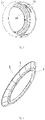
Fig. 3 is a perspective view of a dust scraping device for a filter screen according to the present disclosure; -
Fig. 4 is a perspective view of a skirt partitioning device according to the present disclosure; -
Fig. 5 is a left view of a skirt partitioning device according to the present disclosure, in which a material of an outer ring of a skirt main body is partially removed; and -
Fig. 6 is a left view of a skirt partitioning device according to the present disclosure, in which no material is removed. - Reference numerals:
- 1: inner ring;
- 2: skirt main body;
- 3: collapsing portion;
- 10: cyclone separation unit; 11: filter screen;
- 20: dust cup; 21: dust cup air inlet; 22: dust cup end cover;
- 30: connection base; 31: engagement slot;
- 40: dust scrapping ring mounting rack;
- 50: dust scraping ring; 51: mounting ring; 52: annular dust scraping plate;
- 60: main machine; 61: main machine housing; 62: blower; 63: engagement block;
- 70: supporting washer;
- 80: main body; 81: handheld portion; 82: first transverse connection portion; 83: second transverse connection portion;
- 90: integrated filter element;
- 100: battery pack.
- In order to better explain the present disclosure and facilitate understanding, exemplary embodiments of the present disclosure will be described in detail below in conjunction with the accompanying drawings. Terms such as "upper," "lower," "left" and "right" used herein refer to orientations shown in
Fig. 1 . A side where amain body 80 is located is defined as "lower," and a side where adust cup 20 and amain machine 60 are located is defined as "upper." - The inventors have found during research that the dust cup needs to be cleaned after being used for a period of time, and during cleaning, the dust cup is removed from the main body of the cleaning apparatus and cleaned. Moreover, after the cleaning apparatus is used for a period of time, hair and other dirt may be easily wound around an outer circumference of a filter screen in the cyclone separation unit, which makes it difficult to clean the cleaning apparatus.
- In an aspect, referring to
Fig. 1 , embodiments of the present disclosure provide a cleaning apparatus, including amain body 80, amain machine 60 mounted on themain body 80, adust cup 20, and a removalcyclone separation unit 10 arranged in thedust cup 20. The cleaning apparatus further includes a dust scraping device used for the cleaning apparatus. - The
dust cup 20 and themain machine 60 are arranged on themain body 80, and the dust scraping device is fixedly mounted on thedust cup 20 and coupled to themain machine 60 by an engagement structure. - The
main machine 60 includes amain machine housing 61 and ablower 62 mounted in themain machine housing 61. - A lower end surface of the
main machine housing 61 extends outwards and forms a cylindrical connection end. Three engagement blocks 63 are integrally formed and arranged at equal intervals outside the connection end, and the engagement blocks are fitted, engaged and fixed withengagement slots 31 formed in the dust scraping device on thedust cup 20. Due to the arrangement of the engagement blocks 63 and theengagement slots 31, thedust cup 20 and themain machine 60 can be assembled or disassembled quickly and conveniently. - The
blower 62 is electrically coupled to a master control circuit within themain body 80 and is used to draw in external air. - Based on the above technical solutions, referring to
Fig. 2 andFig. 3 , the dust scraping device includes a dust scraping member; and the dust scraping member has a connection portion extending in a removal direction of thecyclone separation unit 10, and a dust scraping portion extending to an interior of thedust cup 20 in a direction perpendicular to the removal direction and slidably abutting against thecyclone separation unit 10. - The
dust cup 20 has a cylindrical dust cup main body and an open portion arranged at an end of the dust cup main body; the dust scraping member is a cylindricaldust scraping ring 50; and thedust scraping ring 50 is coaxially mounted at the open portion of thedust cup 20. - The
cyclone separation unit 10 is coaxially arranged within thedust cup 20, thecyclone separation unit 10 includes acylindrical filter screen 11 and a cyclone separation portion located downstream of thefilter screen 11. Thedust scraping ring 50 is capable of scrapping off debris on an outer side of thefilter screen 11, and the debris falls into thedust cup 20. - The
main body 80 has a gun-shaped structure, and includes a firsttransverse connection portion 82 substantially extending transversely and ahandheld portion 81 substantially extending longitudinally. A fluid channel substantially extending transversely is arranged in the firsttransverse connection portion 82; and the fluid channel has a first end used as an air inlet and a second end coupled to a dustcup air inlet 21 of thedust cup 20. A dusty air flow enters thedust cup 20 from the air inlet of the fluid channel of the firsttransverse connection portion 82 and through the dustcup air inlet 21, and is subjected to dust and gas separation by thecyclone separation unit 10 coaxially arranged in thedust cup 20. Referring toFig. 1 , a first cyclone separation stage is formed between thefilter screen 11 and an inner wall of thedust cup 20, and the dusty air flow may be subjected to primary dust and gas separation by the first cyclone separation stage. A skirt partitioning device is arranged at a left end, away from the open portion, of thefilter screen 11, and the skirt partitioning device divides an inner chamber of thedust cup 20 into a cyclone separation section (i.e., the first cyclone separation stage) and a dirt collection section. - Specifically, the dusty air flow entering the
dust cup 20 is firstly subjected to first cyclone separation around the outer circumference of thefilter screen 11, and the first cyclone separation stage is formed between thefilter screen 11 and thedust cup 20, wherein dirt separated by the first cyclone separation stage is collected in a first dirt collecting region. Then, a gas separated by the first cyclone separation stage enters a plurality of cyclone cones inside thefilter screen 11 via holes in thefilter screen 11 so as to be subjected to second cyclone separation, and the plurality of cyclone cones inside thefilter screen 11 form a second cyclone separation stage. Dirt separated by the second cyclone separation stage is discharged from dirt outlets of all the cyclone cones and is collected. Referring toFig. 1 , a second dirt collecting region is arranged on the left side of each of the cyclone cones and is used for collecting the dirt discharged by each of the cyclone cones. The gas separated by the second cyclone separation stage is discharged to a downstream HEPA filter device and the like via air outlets of the cyclone cones and is finally discharged to the outside. - It should be noted that the
filter screen 11 is a perforated plate made of a hard material, such as a metal plate. The holes are provided for the purposes of facilitating the passing of the gas separated by the first cyclone separation stage and ensuring that larger-sized dirt is intercepted on the outer side of thefilter screen 11 by thefilter screen 11. The plurality of cyclone cones of the second cyclone separation stage are annularly arranged, and accommodating spaces are formed among the left ends of the plurality of cyclone cones and are used for accommodating a certain dirt in the second dirt collecting region. - Specifically, due to the adoption of the structure that the plurality of cyclone cones are annularly arranged, space is sufficiently utilized during layout of the
cyclone separation unit 10, and thecyclone separation unit 10 is compact in structure. Moreover, thecyclone separation unit 10 allows more cyclones to be arranged in the finite space, and thus, the dust and gas separation efficiency of thecyclone separation unit 10 is increased. - The dust scraping device includes a dust scraping member, and the dust scraping member has a connection portion extending in a removal direction of the
cyclone separation unit 10 and a dust scraping portion extending to an interior of thedust cup 20 in a direction perpendicular to the removal direction and slidably abutting against thecyclone separation unit 10. - The
dust cup 20 has a cylindrical dust cup main body and an open portion arranged on one end of the dust cup main body, the dust scraping member is a cylindricaldust scraping ring 50, and thedust scraping ring 50 is coaxially mounted on the open portion of thedust cup 20. - A skirt partitioning device is fixedly mounted at a bottom of the
cyclone separation unit 10. When thecyclone separation unit 10 is removed from thedust cup 20, the dust scraping device is used to scrape off debris on a first surface of a skirtmain body 2 on the skirt partitioning device on the bottom of thecyclone separation unit 10 into thedust cup 20. - It should be noted that the space between the
dust cup 20 and thecyclone separation unit 10 is used as a separation chamber. The left side of the separation chamber is referred to as a dirt collection section, and the right side of the separation chamber is referred to as a cyclone separation section. When a dust collector is used to clean a lower to-be-cleaned surface such as the ground, a sofa and a bed, the dirt collection section is located on the lower side of the cyclone separation section along a gravity direction, which is beneficial to the concentration of dust to the dirt collection section under the action of its gravity. - Based on the
above embodiment 1 andembodiment 2, the side wall of the dust cup main body has a dustcup air inlet 21 communicating with an air inlet tube. An external dusty air flow drawn in by ablower 62 enters from the air inlet tube and enters the separation chamber via the dustcup air inlet 21 so as to be subjected to dust and gas separation. Moreover, when a cleaning apparatus is used, generally, the dirt collection section is located on the lower side of the cyclone separation section in a gravity direction, and therefore, dirt separated by the separation chamber is accumulated on the dirt collection section under the action of gravity. The air inlet tube is disposed on a firsttransverse connection portion 82 of amain body 80 and communicates with the dustcup air inlet 21, and a structure enabling an intake dusty air flow to spirally advance is arranged in theair inlet tube 10. Specifically, the linear advance of the dusty air flow is changed into spiral advance, so that the centrifugal force is increased, and the dust collection effect is improved. The left end of thedust cup 20 has a dust pouring opening and a dust cup end cover 22 capable of sealing the dust pouring opening, the dustcup end cover 22 is mounted on the dust cup main body by a hinged piece, and the top end of the dust cup end cover 22 passes through an engagement member so that the dustcup end cover 22 is kept on a closed position. Specifically, the dustcup end cover 22 is capable of rotating between the closed position and an open position. On the closed position, the dustcup end cover 22 keeps the dirt on the dirt collection section; and on the open position, the dirt may be removed from the dirt collection section. - Further, the
dust scraping ring 50 has an L-shaped radial section, the connection portion being a transverse portion of the L-shaped radial section, and the dust scraping portion being a vertical portion of the L-shaped radial section. The L-shaped structure is simple and is more compact than that in the related art, moreover, the spatial proportion is small, so that interference with other components on thedust scraping ring 50 and thecyclone separation unit 10 is minimized. The radial section is not limited to be L-shaped and may also be of a T-shaped structure. - Further, the
dust scraping ring 50 includes a mountingring 51 and an annulardust scraping plate 52. An outer wall of the mountingring 51 is fixedly coupled to the interior of thedust cup 20. The annulardust scraping plate 52 is an L-shaped vertical dust scraping portion and is integrally formed on the side, located on the open portion of thedust cup 20, of the mountingring 51 and radially extends inwards to abut against thefilter screen 11. When thecyclone separation unit 10 is removed from thedust cup 20, thefilter screen 11 slides past the annulardust scraping plate 52 and the debris is scraped off. - Further, an initial position of the annular
dust scraping plate 52 is a position where an inner ring of the annulardust scraping plate 52 abuts against aseat 111 of thefilter screen 11, so that the annulardust scraping plate 52 scrapes off dust from thefilter screen 11 on theseat 111 of thefilter screen 11, then, it is ensured that the dust on theoverall filter screen 11 may be scraped off by thedust scraping ring 50, and thus, the dust scraping effect of the annulardust scraping plate 52 is improved. - Further, the dust scraping device further includes a
connection base 30 coaxial with thedust scraping ring 50 and a dust scrapingring mounting rack 40. Theconnection base 30 is fixed to the open portion of thedust cup 20, the dust scrapingring mounting rack 40 is arranged in theconnection base 30, and the side, away from the open portion, of the dust scrapingring mounting rack 40 is fixedly coupled to thedust scraping ring 50. Preferably, thedust scraping ring 50 is detachably coupled to the dust scrapingring mounting rack 40, so that it is convenient to replace thedust scraping ring 50. - Specifically, a positioning boss is formed between the
connection base 30 and the dustscraping mounting rack 40. The positioning boss is used for limiting the peripheral direction of thedust scraping ring 50 on thedust cup 20 and then fixing theconnection base 30 and thedust cup 20 in a glue bonding manner. - Further, based on the above technical solutions, referring to
Fig. 2 , the dust scraping device in the present embodiment further includes a supportingwasher 70 coaxially arranged in the mountingring 51, the outer peripheral surface of the supportingwasher 70 abuts against the inner peripheral surface of the mountingring 51, the end of the supportingwasher 70 abuts against the annulardust scraping plate 52, and the supportingwasher 70 is used for supporting the mountingring 51 and the annulardust scraping plate 52, so that the overall strength of thedust scraping ring 50 and the dust scraping effect are improved. Moreover, thedust cup 20 is coaxially coupled to amain machine 60 by an engagement structure. The dust scraping device is arranged on the open portion, coupled to amain machine housing 61, of thedust cup 20. - Further, an annular positioning step is formed at a junction between an inner side wall of the
connection base 30 and the dust scrapingring mounting rack 40 and is used to position thecyclone separation unit 10; a cooperation step is formed at thecyclone separation unit 10 and cooperates with the annular positioning step. Thecyclone separation unit 10 is mounted in such a way that the cyclone separation unit is exactly engaged with the positioning step, and theseat 111 on thefilter screen 11 abuts against the annulardust scraping plate 52, precisely positioning and rapidly mounting thecyclone separation unit 10. - Further, a seal ring is arranged between the annular positioning step and the cooperation step, so that the sealing property for connection between the
cyclone separation unit 10 and thedust cup 20 is improved. - Further, the
dust scraping ring 50 is made of a rubber material such as a TPU material, so that the performance of deformability of thedust scraping ring 50 moving relative to thecyclone separation unit 10 is improved, and interference with components such as the skirt partitioning device in thecyclone separation unit 10 is convenient to generate. - Referring to
Fig. 4 to Fig. 6 , a skirt partitioning device is mounted on a cyclone separation unit of a cleaning apparatus. The skirt partitioning device is of an annular structure. The skirt partitioning device includes an annularinner ring 1 and an annular skirtmain body 2. - The skirt
main body 2 has a root coupled to theinner ring 1 and an edge part at an end, away from theinner ring 1, of the skirtmain body 2. A diameter of the edge part is greater than a diameter of the root. A plurality of collapsingportions 3 are formed on the skirtmain body 2 and arranged at intervals in a peripheral direction of the skirtmain body 2, and each of the collapsingportions 3 is of a strip-shaped structure extending in a radial direction of the skirtmain body 2. - In a thickness direction of the skirt
main body 2, the collapsingportions 3 protrude on a first side surface of the skirtmain body 2 relative to the skirtmain body 2 and are recessed on a second side surface of the skirtmain body 2 relative to the skirtmain body 2. Moreover, on the first side surface of the skirtmain body 2, the size of each of the collapsingportions 3 protruding beyond the skirtmain body 2 is gradually reduced from the root to the edge part. - The present disclosure provides the skirt partitioning device including the
inner ring 1 and the skirtmain body 2. The plurality of collapsingportions 3 are formed on the skirtmain body 2; and the collapsingportions 3 protrude on the first side surface of the skirtmain body 2 relative to the skirtmain body 2 and are recessed on the second side surface of the skirtmain body 2 relative to the skirtmain body 2. Moreover, on the first side surface of the skirtmain body 2, the size of each of the collapsingportions 3 protruding beyond the skirtmain body 2 is gradually reduced from the root to the edge part. Compared with the related art, the skirt partitioning device is simple in structure while playing a separation role; moreover, the collapsingportions 3 reasonable in layout, arc-shaped connection portions formed between the adjacent collapsingportions 3 are easy to deform to facilitate the passing of dirt, so that the overall skirt partitioning device is moderate in structural hardness and is less likely to interfere with components on the dust cup, and meanwhile, the dirt is effectively separated, so that the dirt smoothly enters a dirt collection section. - Further, on the second side surface of the skirt
main body 2, the size of each of the collapsingportions 3 recessed in the skirtmain body 2 is gradually reduced from the root to the edge part; and/or the size of each of the collapsingportions 3 extending in the peripheral direction of the skirtmain body 2 is gradually reduced from the root to the edge part. It is ensured that the dirt is effectively separated, and meanwhile, it is convenient for the dirt to smoothly enter the dirt collection section. - Further, referring to
Fig. 5 , a first arc-shapedconnection portion 31 is formed on a first side of each of the collapsingportions 3 in the peripheral direction of the skirtmain body 2, and a second arc-shapedconnection portion 32 is formed on a second side of each of the collapsingportions 3, wherein the second arc-shapedconnection portion 32 of one of the collapsingportions 3 is coupled to the first arc-shapedconnection portion 31 of the other adjacent collapsingportion 3, and an arc-shaped connection portion is formed between each of the collapsingportions 3 and the first side surface of the skirtmain body 2, so that the appearance is beautiful. - It should be noted that the first side surface of the skirt
main body 2 is defined as a surface where a junction of the first arc-shapedconnection portion 31 and the second arc-shapedconnection portion 32 is located. - Further, an arc-shaped connection portion is formed between each of the collapsing
portions 3 and the second side surface of the skirtmain body 2. - Further, a third arc-shaped connection portion is formed on one side of each of the collapsing
portions 3 in the peripheral direction of the skirtmain body 2, and a fourth arc-shaped connection portion is formed on the second side of each of the collapsingportions 3, wherein the fourth arc-shaped connection portion of one of the collapsingportions 3 is coupled to the third arc-shaped connection portion of the other adjacent collapsingportion 3. - Further, on the first side surface of the skirt
main body 2, the sizes of the collapsingportions 3 protruding beyond the skirtmain body 2 are gradually reduced from the root to the edge part until disappear; and on the second side surface of the skirtmain body 2, the sizes of the collapsingportions 3 recessed in the skirtmain body 2 are gradually reduced from the root to the edge part until disappear, so that the edge part is smooth; and/or theinner ring 1 is an annular structural member, the inner side wall of theinner ring 1 has an engagement portion coupled to acyclone separation unit 10, and the engagement portion facilitates the mounting and dismounting of theinner ring 1 and thecyclone separation unit 10. Theinner ring 1 is integrally formed with the root in a peripheral direction of an outer side wall of the inner ring. Theinner ring 1 and the root of the skirtmain body 2 form wavy shapes in the peripheral direction of the outer side wall of the inner ring. An annular engagement slot is formed in the left side end of theinner ring 1 and is assembled together with the bottom of thecyclone separation unit 10. - Further, the skirt partitioning device is made of silicon rubber. The silicon rubber material is good in deformation effect and facilitates the smooth passing of the dirt.
- The skirt partitioning device forms an angle towards an outer wall of a
dust cup 20 and extends away from a central axis; and/or thedust cup 20 includes a cylindrical main body. A dustcup end cover 22 is arranged at a first end of the cylindrical main body in an axis direction of the cylindrical main body, and an open portion is arranged on a second end of the cylindrical main body. The skirt partitioning device is located in the middle of the cylindrical main body, wherein a dirt collection section is formed between the dustcup end cover 22 and the skirt partitioning device, a cyclone separation section is formed between the open portion and the skirt partitioning device, and the skirt main body obliquely extends to the dirt collection section. - Further, the skirt
main body 2 is made of an elastically deformable material. - The skirt
main body 2 is extruded and deformed toward the central axis and away from the open portion on thedust cup 20, so that the skirtmain body 2 is located on a first position; and the skirtmain body 2 is extruded and deformed in a direction opposite to the first position, so that the skirtmain body 2 is located on a second position. In such a way, the skirtmain body 2 deforms between the first position and the second position. - Specifically, in a process that the cyclone separation unit is removed from the interior of the
dust cup 20, when passing through a dust scraping structure, the skirtmain body 2 is pressed to shrink and deform in a direction opposite to a removal direction of the cyclone separation unit and generate crumples on the positions of the collapsing portions 3 (which is similar to the state that an umbrella is folded), so that the skirtmain body 2 is located on the first position; and after passing through the dust scraping structure, the skirtmain body 2 is automatically restored to an unfolded state under the action of an elastic restoring force itself. In a process that the cyclone separation unit is mounted in thedust cup 20, when passing through the dust scraping structure, the skirtmain body 2 is pressed to deform in a direction opposite to a mounting direction of the cyclone separation unit, so that the skirtmain body 2 is located on the second position; and after passing through the dust scraping structure, the skirtmain body 2 is automatically restored to an unfolded state under the action of an elastic restoring force itself. - A specific working manner of the skirt partitioning device is that: in a first case, when large-sized dirt moves from a cyclone separation chamber to a dirt collection chamber, a force generated when the dirt acts on the skirt
main body 2 may cause deformation of the arc-shaped connection portion formed between the adjacent collapsing portions of the skirtmain body 2. Therefore, a stressed position of the skirtmain body 2 may deform to allow the dirt to smoothly pass by. - In a second case, in a process that the
cyclone separation unit 10 is dismounted, specifically, it is determined whether the skirtmain body 2 is required to be folded according to the size of a removal opening of thecyclone separation unit 10. - Interference occurs when a dust scraping device on the
dust cup 20 and the skirtmain body 2 fixedly arranged on thecyclone separation unit 10 pass, and the arc-shaped connection portions formed between the adjacent collapsing portions deform and are stressed to be folded. - If the
cyclone separation unit 10 may be removed and the size of the open portion on thedust cup 20 is large enough, the skirtmain body 2 is not folded and is directly removed. - Further, the cleaning apparatus further includes an
integrated filter element 90 which is arranged on an outlet end of a cyclone cone and is used for filtering air separated at a second cyclone separation stage again. Theintegrated filter element 90 is detachably arranged in the cyclone separation unit so as to be conveniently replaced. Meanwhile, air separated from a second separation unit is further filtered by theintegrated filter element 90, so that fewer impurities in the air are discharged to the outside, and a dust collection effect is better. - In the description of the present disclosure, it should be understood that terms such as "first" and "second" are used herein for purposes of description and are not intended to indicate or imply relative importance or significance or to imply the number of indicated technical features. Thus, the feature defined with "first" and "second" may comprise one or more of this feature. In the description of the present disclosure, the term "a plurality of' means two or more than two, unless specified otherwise.
- In the present disclosure, unless specified or limited otherwise, the terms "mounted," "connected," "coupled," "fixed" and the like are used broadly, and may be, for example, fixed connections, detachable connections, or integral connections; may also be mechanical or electrical connections; may also be direct connections or indirect connections via intervening structures; may also be inner communications of two elements, which can be understood by those skilled in the art according to specific situations.
- In the present disclosure, unless specified or limited otherwise, a structure in which a first feature is "on" or "below" a second feature may include an embodiment in which the first feature is in direct contact with the second feature, and may also include an embodiment in which the first feature and the second feature are not in direct contact with each other, but are contacted via an additional feature formed therebetween. Furthermore, a first feature "on," "above," or "on top of' a second feature may include an embodiment in which the first feature is right or obliquely "on," "above," or "on top of' the second feature, or just means that the first feature is at a height higher than that of the second feature; while a first feature "below," "under," or "on bottom of' a second feature may include an embodiment in which the first feature is right or obliquely "below," "under," or "on bottom of' the second feature, or just means that the first feature is at a height lower than that of the second feature.
- Reference throughout this specification to "an embodiment," "some embodiments," "one embodiment", "an example," "a specific example," or "some examples," means that a particular feature, structure, material, or characteristic described in connection with the embodiment or example is included in at least one embodiment or example of the present disclosure. Thus, these phrases in various places throughout this specification are not necessarily referring to the same embodiment or example of the present disclosure. Furthermore, the particular features, structures, materials, or characteristics may be combined in any suitable manner in one or more embodiments or examples. Moreover, different embodiments or examples as well as features in different embodiments or examples described in the present disclosure may be combined or integrated by those skilled in the art.
- Although embodiments of the present disclosure have been shown and described, it would be appreciated by those skilled in the art that the above embodiments are exemplary and cannot be construed to limit the present disclosure, and changes, modifications, alternatives and variations can be made in the embodiments without departing from the scope of the present disclosure.
Claims (15)
- A dust scraping device for a cleaning apparatus, the cleaning apparatus comprising a dust cup (20) and a removable cyclone separation unit (10) arranged in the dust cup (20),
wherein:the dust scraping device comprises a dust scraping member,the dust scraping member has a connection portion extending in a removal direction of the cyclone separation unit (10), and a dust scraping portion extending to an interior of the dust cup (20) in a direction perpendicular to the removal direction and slidably abutting against the cyclone separation unit (10); andthe dust scraping device is mounted at the dust cup (20), and the dust scraping portion scrapes off at least part of debris on an outer side of the cyclone separation unit (10) when the cyclone separation unit (10) is removed from the dust cup (20). - The dust scraping device according to claim 1, wherein:the dust cup (20) has a cylindrical dust cup main body and an open portion arranged at an end of the dust cup main body;the dust scraping member is a cylindrical dust scraping ring (50), and the dust scraping ring (50) is coaxially mounted at the open portion of the dust cup (20);the cyclone separation unit (10) is coaxially arranged within the dust cup (20), and the cyclone separation unit (10) comprises a cylindrical filter screen (11) and a cyclone separation portion located downstream of the filter screen (11); andthe dust scraping ring (50) scrapes off debris on an outer side of the filter screen (11).
- The dust scraping device according to claim 2, wherein the dust scraping ring (50) has an L-shaped radial section, the connection portion being a transverse portion of the L-shaped radial section, and the dust scraping portion being a vertical portion of the L-shaped radial section.
- The dust scraping device according to claim 2 or 3, wherein:the dust scraping ring (50) comprises a mounting ring (51) and an annular dust scraping plate (52);an outer wall of the mounting ring (51) is fixedly coupled to the interior of the dust cup (20);the annular dust scraping plate (52) is integrally formed on a side, away from the open portion, of the mounting ring (51), radially extends inwards, and abuts against the filter screen (11); andthe filter screen (11) slides past the annular dust scraping plate (52) and debris is scraped off when the cyclone separation unit (10) is removed from the dust cup (20).
- The dust scraping device according to claim 4, further comprising:a connection base (30) arranged coaxially with the dust scraping ring (50) and fixed to the open portion of the dust cup (20); anda dust scraping ring mounting rack (40) arranged coaxially with the dust scraping ring (50) and in the connection base (30), a side, away from the open portion, of the dust scraping ring mounting rack (40) being fixedly coupled to the mounting ring (51).
- The dust scraping device according to claim 4 or 5, further comprising:a supporting washer (70) arranged coaxially in the mounting ring (51),wherein:the supporting washer (70) has an outer peripheral surface of the supporting washer (70) abutting against an inner peripheral surface of the mounting ring (51),the supporting washer (70) has an end abutting against the annular dust scraping plate (52) and supports the mounting ring (51) and the annular dust scraping plate (52).
- The dust scraping device according to any one of claims 4 to 6, wherein an initial position of the annular dust scraping plate (52) is a position where an inner ring of the annular dust scraping plate (52) abuts against a seat (111) of the filter screen (11).
- The dust scraping device according to any one of claims 5 to 7, wherein:an annular positioning step is formed at a junction between an inner side wall of the connection base (30) and the dust scraping ring mounting rack (40) and positions the cyclone separation unit (10);a cooperation step is formed at the cyclone separation unit (10) and cooperates with the annular positioning step; anda seal ring is arranged between the annular positioning step and the cooperation step.
- The dust scraping device according to any one of claims 2 to 8, wherein the dust scraping ring (50) is made of a rubber material.
- A cleaning apparatus, comprising:a gun-shaped main body (80);a main machine (60) mounted on the main body (80);a dust cup (20);a removable cyclone separation unit (10) arranged in the dust cup (20); andthe dust scraping device according to any one of claims 1 to 9,wherein the dust cup (20) and the main machine (60) are arranged on the main body (80), and the dust scraping device is fixedly mounted at the dust cup (20) and is coupled to the main machine (60) by an engagement structure.
- The cleaning apparatus according to claim 10, further comprising a skirt partitioning device mounted at a bottom of the cyclone separation unit (10), wherein the skirt partitioning device comprises an annular inner ring (1) and an annular skirt main body (2).
- The cleaning apparatus according to claim 11, wherein:the skirt main body (2) has a root coupled to the inner ring (1) and an edge part at an end, away from the inner ring (1), of the skirt main body (2), andthe edge part has a diameter greater than the root.
- The cleaning apparatus according to claim 11 or 12, wherein:a plurality of collapsing portions (3) are formed on the skirt main body (2) and arranged at intervals in a peripheral direction of the skirt main body (2), andeach of the collapsing portions (3) has a strip-shaped structure extending in a radial direction of the skirt main body (2).
- The cleaning apparatus according to any one of claims 11 to 13, wherein:
the collapsing portions (3) protrude on a first side surface of the skirt main body (2) relative to the skirt main body (2) and are recessed on a second side surface of the skirt main body (2) relative to the skirt main body (2), in a thickness direction of the skirt main body (2). - The cleaning apparatus according to claim 14, wherein:a size of each collapsing portion (3) protruding beyond the skirt main body (2) on the first side surface of the skirt main body (2) is gradually reduced from the root to the edge part; and/ora size of each collapsing portion (3) recessed in the skirt main body (2) on the second side surface of the skirt main body (2) is gradually reduced from the root to the edge part.
Applications Claiming Priority (1)
| Application Number | Priority Date | Filing Date | Title |
|---|---|---|---|
| CN202121089446.8U CN216020766U (en) | 2021-05-20 | 2021-05-20 | Dust scraping device for cleaning equipment and cleaning equipment with dust scraping device |
Publications (2)
| Publication Number | Publication Date |
|---|---|
| EP4091512A1 true EP4091512A1 (en) | 2022-11-23 |
| EP4091512B1 EP4091512B1 (en) | 2025-07-16 |
Family
ID=79185409
Family Applications (1)
| Application Number | Title | Priority Date | Filing Date |
|---|---|---|---|
| EP21217965.9A Active EP4091512B1 (en) | 2021-05-20 | 2021-12-28 | Dust scraping device and cleaning apparatus |
Country Status (5)
| Country | Link |
|---|---|
| US (1) | US11717122B2 (en) |
| EP (1) | EP4091512B1 (en) |
| JP (1) | JP7248773B2 (en) |
| KR (1) | KR102629161B1 (en) |
| CN (1) | CN216020766U (en) |
Families Citing this family (6)
| Publication number | Priority date | Publication date | Assignee | Title |
|---|---|---|---|---|
| JP1757574S (en) * | 2022-05-30 | 2023-11-15 | vacuum cleaner main unit | |
| CN115944240A (en) * | 2022-12-28 | 2023-04-11 | 苏州锐科兰电器有限公司 | Dust collection device and vacuum cleaner |
| EP4684712A1 (en) * | 2023-03-22 | 2026-01-28 | Guangdong Deerma Technology Co., Ltd. | Cleaning device |
| CN116406994B (en) * | 2023-03-24 | 2026-01-23 | 珠海格力电器股份有限公司 | Modularized mite removing instrument |
| CN116687261A (en) * | 2023-07-13 | 2023-09-05 | 苏州尚腾科技制造有限公司 | A dust cup with a knob type dust scraping structure |
| CN120345822B (en) * | 2025-06-25 | 2025-09-12 | 珠海格力电器股份有限公司 | Dust-gas separation device and cleaning equipment |
Citations (6)
| Publication number | Priority date | Publication date | Assignee | Title |
|---|---|---|---|---|
| JP2002051953A (en) * | 2000-08-07 | 2002-02-19 | Sharp Corp | Electric vacuum cleaner |
| EP3405087A1 (en) * | 2016-01-22 | 2018-11-28 | Dyson Technology Limited | Vacuum cleaner |
| US20190200824A1 (en) * | 2017-12-30 | 2019-07-04 | Dyson Technology Limited | Dirt separator |
| CN111449568A (en) * | 2020-04-29 | 2020-07-28 | 安克创新科技股份有限公司 | Dust collector and cleaning device |
| WO2021036039A1 (en) * | 2019-08-30 | 2021-03-04 | 追创科技(苏州)有限公司 | Ash scraping structure |
| CN112568782A (en) * | 2020-12-28 | 2021-03-30 | 追创科技(苏州)有限公司 | Double-effect ash scraping cleaning device and ash scraping method |
Family Cites Families (13)
| Publication number | Priority date | Publication date | Assignee | Title |
|---|---|---|---|---|
| KR100518804B1 (en) | 2003-03-31 | 2005-10-06 | 삼성광주전자 주식회사 | Filter cleaning device of cyclone vacuum cleaner |
| KR100485699B1 (en) | 2003-04-14 | 2005-04-28 | 삼성광주전자 주식회사 | Filter assembly for cyclone-type dust collecting apparatus of vacuum cleaner |
| JP2005168775A (en) * | 2003-12-11 | 2005-06-30 | Sharp Corp | Electric vacuum cleaner |
| KR100880492B1 (en) * | 2005-05-12 | 2009-01-28 | 엘지전자 주식회사 | Dust collection unit for vacuum cleaner |
| DE202010014791U1 (en) * | 2010-10-27 | 2012-01-30 | Geka Gmbh | Rectangular scraper for flat brushes |
| CN105249891B (en) | 2015-11-03 | 2018-01-30 | 莱克电气股份有限公司 | A kind of three-level cyclone dirt cup filtration system and the dust catcher comprising the system |
| GB2569820B (en) * | 2017-12-30 | 2020-07-08 | Dyson Technology Ltd | A cleaning appliance |
| GB2569819A (en) * | 2017-12-30 | 2019-07-03 | Dyson Technology Ltd | A dirt separator |
| GB2569821B (en) * | 2017-12-30 | 2020-04-29 | Dyson Technology Ltd | A cleaning appliance |
| CN108814420B (en) * | 2018-07-17 | 2020-10-02 | 苏州爱普电器有限公司 | Cyclone separator and vacuum cleaner |
| US11944258B2 (en) * | 2018-09-14 | 2024-04-02 | Lg Electronics Inc. | Filter and vacuum canister cleaner |
| US11523721B2 (en) * | 2018-09-14 | 2022-12-13 | Lg Electronics Inc. | Vacuum cleaner |
| KR102253662B1 (en) * | 2019-09-30 | 2021-05-18 | 엘지전자 주식회사 | Clearner |
-
2021
- 2021-05-20 CN CN202121089446.8U patent/CN216020766U/en active Active
- 2021-12-27 JP JP2021211898A patent/JP7248773B2/en active Active
- 2021-12-28 EP EP21217965.9A patent/EP4091512B1/en active Active
- 2021-12-28 US US17/563,382 patent/US11717122B2/en active Active
- 2021-12-30 KR KR1020210192896A patent/KR102629161B1/en active Active
Patent Citations (6)
| Publication number | Priority date | Publication date | Assignee | Title |
|---|---|---|---|---|
| JP2002051953A (en) * | 2000-08-07 | 2002-02-19 | Sharp Corp | Electric vacuum cleaner |
| EP3405087A1 (en) * | 2016-01-22 | 2018-11-28 | Dyson Technology Limited | Vacuum cleaner |
| US20190200824A1 (en) * | 2017-12-30 | 2019-07-04 | Dyson Technology Limited | Dirt separator |
| WO2021036039A1 (en) * | 2019-08-30 | 2021-03-04 | 追创科技(苏州)有限公司 | Ash scraping structure |
| CN111449568A (en) * | 2020-04-29 | 2020-07-28 | 安克创新科技股份有限公司 | Dust collector and cleaning device |
| CN112568782A (en) * | 2020-12-28 | 2021-03-30 | 追创科技(苏州)有限公司 | Double-effect ash scraping cleaning device and ash scraping method |
Also Published As
| Publication number | Publication date |
|---|---|
| JP7248773B2 (en) | 2023-03-29 |
| KR20220157280A (en) | 2022-11-29 |
| US11717122B2 (en) | 2023-08-08 |
| KR102629161B1 (en) | 2024-01-29 |
| EP4091512B1 (en) | 2025-07-16 |
| JP2022179304A (en) | 2022-12-02 |
| CN216020766U (en) | 2022-03-15 |
| US20220369878A1 (en) | 2022-11-24 |
Similar Documents
| Publication | Publication Date | Title |
|---|---|---|
| EP4091512B1 (en) | Dust scraping device and cleaning apparatus | |
| RU2253348C1 (en) | Filter cleaning apparatus for cyclone type vacuum cleaner | |
| JP5814028B2 (en) | Vacuum cleaner with latch mechanism | |
| JP3964854B2 (en) | Filter assembly for cyclone dust collector of vacuum cleaner | |
| RU2242158C2 (en) | Cyclone-type dust-catching apparatus for use in vacuum cleaner | |
| US10856712B2 (en) | Three-tier cyclone dust bin filtration system and vacuum cleaner comprising the system | |
| CN101836847B (en) | Filter locking arrangement for a vacuum cleaner | |
| CN1679439B (en) | Filtering device for vacuum cleaner | |
| JP7727532B2 (en) | Hem separator device and its cleaning equipment | |
| RU2262287C1 (en) | Filtering unit for vacuum cleaner (versions) and dust catcher with filtering unit | |
| CN102497799A (en) | Dust collecting apparatus for a vacuum cleaner having a dust removal function | |
| CN111265143B (en) | Dust separating device and cleaning equipment | |
| EP4491076B1 (en) | Filtering assembly, vacuum cleaner and cleaning set | |
| JP2003339593A (en) | Vacuum cleaner | |
| CN109984674B (en) | Gas-dust separation screen, gas-dust separation system and dust collector | |
| CN111359315B (en) | Dust removal equipment | |
| CN202801483U (en) | Electric dust collector | |
| EP1692991B1 (en) | Dust collector for vacuum cleaner | |
| CN115670289B (en) | Cleaning equipment with high-efficient simple and convenient ash scraping structure | |
| CN223196009U (en) | Cyclone separation device and handheld vacuum cleaner | |
| CN210130780U (en) | Gas-dust separation mesh enclosure, gas-dust separation system and dust collector | |
| KR20010054396A (en) | Cyclone type vacuum cleaner | |
| CN218792043U (en) | Vacuum cleaner | |
| CN215305481U (en) | Cyclone type dust collector dust cup easy for cleaning hair winding technology | |
| WO2025002389A1 (en) | Dust collection base station and sweeping robot system having same |
Legal Events
| Date | Code | Title | Description |
|---|---|---|---|
| PUAI | Public reference made under article 153(3) epc to a published international application that has entered the european phase |
Free format text: ORIGINAL CODE: 0009012 |
|
| STAA | Information on the status of an ep patent application or granted ep patent |
Free format text: STATUS: REQUEST FOR EXAMINATION WAS MADE |
|
| 17P | Request for examination filed |
Effective date: 20211228 |
|
| AK | Designated contracting states |
Kind code of ref document: A1 Designated state(s): AL AT BE BG CH CY CZ DE DK EE ES FI FR GB GR HR HU IE IS IT LI LT LU LV MC MK MT NL NO PL PT RO RS SE SI SK SM TR |
|
| RBV | Designated contracting states (corrected) |
Designated state(s): AL AT BE BG CH CY CZ DE DK EE ES FI FR GB GR HR HU IE IS IT LI LT LU LV MC MK MT NL NO PL PT RO RS SE SI SK SM TR |
|
| GRAP | Despatch of communication of intention to grant a patent |
Free format text: ORIGINAL CODE: EPIDOSNIGR1 |
|
| STAA | Information on the status of an ep patent application or granted ep patent |
Free format text: STATUS: GRANT OF PATENT IS INTENDED |
|
| INTG | Intention to grant announced |
Effective date: 20250210 |
|
| GRAS | Grant fee paid |
Free format text: ORIGINAL CODE: EPIDOSNIGR3 |
|
| GRAA | (expected) grant |
Free format text: ORIGINAL CODE: 0009210 |
|
| STAA | Information on the status of an ep patent application or granted ep patent |
Free format text: STATUS: THE PATENT HAS BEEN GRANTED |
|
| P01 | Opt-out of the competence of the unified patent court (upc) registered |
Free format text: CASE NUMBER: APP_26271/2025 Effective date: 20250603 |
|
| AK | Designated contracting states |
Kind code of ref document: B1 Designated state(s): AL AT BE BG CH CY CZ DE DK EE ES FI FR GB GR HR HU IE IS IT LI LT LU LV MC MK MT NL NO PL PT RO RS SE SI SK SM TR |
|
| REG | Reference to a national code |
Ref country code: GB Ref legal event code: FG4D |
|
| REG | Reference to a national code |
Ref country code: CH Ref legal event code: EP Ref country code: DE Ref legal event code: R096 Ref document number: 602021034132 Country of ref document: DE |
|
| REG | Reference to a national code |
Ref country code: IE Ref legal event code: FG4D |
|
| REG | Reference to a national code |
Ref country code: NL Ref legal event code: MP Effective date: 20250716 |
|
| PG25 | Lapsed in a contracting state [announced via postgrant information from national office to epo] |
Ref country code: PT Free format text: LAPSE BECAUSE OF FAILURE TO SUBMIT A TRANSLATION OF THE DESCRIPTION OR TO PAY THE FEE WITHIN THE PRESCRIBED TIME-LIMIT Effective date: 20251117 |
|
| PG25 | Lapsed in a contracting state [announced via postgrant information from national office to epo] |
Ref country code: NL Free format text: LAPSE BECAUSE OF FAILURE TO SUBMIT A TRANSLATION OF THE DESCRIPTION OR TO PAY THE FEE WITHIN THE PRESCRIBED TIME-LIMIT Effective date: 20250716 |
|
| REG | Reference to a national code |
Ref country code: AT Ref legal event code: MK05 Ref document number: 1813244 Country of ref document: AT Kind code of ref document: T Effective date: 20250716 |
|
| PG25 | Lapsed in a contracting state [announced via postgrant information from national office to epo] |
Ref country code: IS Free format text: LAPSE BECAUSE OF FAILURE TO SUBMIT A TRANSLATION OF THE DESCRIPTION OR TO PAY THE FEE WITHIN THE PRESCRIBED TIME-LIMIT Effective date: 20251116 |
|
| PGFP | Annual fee paid to national office [announced via postgrant information from national office to epo] |
Ref country code: DE Payment date: 20251126 Year of fee payment: 5 |
|
| PGFP | Annual fee paid to national office [announced via postgrant information from national office to epo] |
Ref country code: GB Payment date: 20251127 Year of fee payment: 5 |
|
| PG25 | Lapsed in a contracting state [announced via postgrant information from national office to epo] |
Ref country code: NO Free format text: LAPSE BECAUSE OF FAILURE TO SUBMIT A TRANSLATION OF THE DESCRIPTION OR TO PAY THE FEE WITHIN THE PRESCRIBED TIME-LIMIT Effective date: 20251016 |
|
| REG | Reference to a national code |
Ref country code: LT Ref legal event code: MG9D |
|
| PG25 | Lapsed in a contracting state [announced via postgrant information from national office to epo] |
Ref country code: AT Free format text: LAPSE BECAUSE OF FAILURE TO SUBMIT A TRANSLATION OF THE DESCRIPTION OR TO PAY THE FEE WITHIN THE PRESCRIBED TIME-LIMIT Effective date: 20250716 |
|
| PG25 | Lapsed in a contracting state [announced via postgrant information from national office to epo] |
Ref country code: FI Free format text: LAPSE BECAUSE OF FAILURE TO SUBMIT A TRANSLATION OF THE DESCRIPTION OR TO PAY THE FEE WITHIN THE PRESCRIBED TIME-LIMIT Effective date: 20250716 |
|
| PG25 | Lapsed in a contracting state [announced via postgrant information from national office to epo] |
Ref country code: HR Free format text: LAPSE BECAUSE OF FAILURE TO SUBMIT A TRANSLATION OF THE DESCRIPTION OR TO PAY THE FEE WITHIN THE PRESCRIBED TIME-LIMIT Effective date: 20250716 |
|
| PGFP | Annual fee paid to national office [announced via postgrant information from national office to epo] |
Ref country code: FR Payment date: 20251124 Year of fee payment: 5 |
|
| PG25 | Lapsed in a contracting state [announced via postgrant information from national office to epo] |
Ref country code: GR Free format text: LAPSE BECAUSE OF FAILURE TO SUBMIT A TRANSLATION OF THE DESCRIPTION OR TO PAY THE FEE WITHIN THE PRESCRIBED TIME-LIMIT Effective date: 20251017 |
|
| PG25 | Lapsed in a contracting state [announced via postgrant information from national office to epo] |
Ref country code: SE Free format text: LAPSE BECAUSE OF FAILURE TO SUBMIT A TRANSLATION OF THE DESCRIPTION OR TO PAY THE FEE WITHIN THE PRESCRIBED TIME-LIMIT Effective date: 20250716 |
|
| PG25 | Lapsed in a contracting state [announced via postgrant information from national office to epo] |
Ref country code: LV Free format text: LAPSE BECAUSE OF FAILURE TO SUBMIT A TRANSLATION OF THE DESCRIPTION OR TO PAY THE FEE WITHIN THE PRESCRIBED TIME-LIMIT Effective date: 20250716 |
|
| PG25 | Lapsed in a contracting state [announced via postgrant information from national office to epo] |
Ref country code: BG Free format text: LAPSE BECAUSE OF FAILURE TO SUBMIT A TRANSLATION OF THE DESCRIPTION OR TO PAY THE FEE WITHIN THE PRESCRIBED TIME-LIMIT Effective date: 20250716 Ref country code: PL Free format text: LAPSE BECAUSE OF FAILURE TO SUBMIT A TRANSLATION OF THE DESCRIPTION OR TO PAY THE FEE WITHIN THE PRESCRIBED TIME-LIMIT Effective date: 20250716 |
|
| PG25 | Lapsed in a contracting state [announced via postgrant information from national office to epo] |
Ref country code: RS Free format text: LAPSE BECAUSE OF FAILURE TO SUBMIT A TRANSLATION OF THE DESCRIPTION OR TO PAY THE FEE WITHIN THE PRESCRIBED TIME-LIMIT Effective date: 20251016 |
|
| PG25 | Lapsed in a contracting state [announced via postgrant information from national office to epo] |
Ref country code: ES Free format text: LAPSE BECAUSE OF FAILURE TO SUBMIT A TRANSLATION OF THE DESCRIPTION OR TO PAY THE FEE WITHIN THE PRESCRIBED TIME-LIMIT Effective date: 20250716 |
|
| PG25 | Lapsed in a contracting state [announced via postgrant information from national office to epo] |
Ref country code: RO Free format text: LAPSE BECAUSE OF FAILURE TO SUBMIT A TRANSLATION OF THE DESCRIPTION OR TO PAY THE FEE WITHIN THE PRESCRIBED TIME-LIMIT Effective date: 20250716 |
|
| PG25 | Lapsed in a contracting state [announced via postgrant information from national office to epo] |
Ref country code: SM Free format text: LAPSE BECAUSE OF FAILURE TO SUBMIT A TRANSLATION OF THE DESCRIPTION OR TO PAY THE FEE WITHIN THE PRESCRIBED TIME-LIMIT Effective date: 20250716 |
|
| PG25 | Lapsed in a contracting state [announced via postgrant information from national office to epo] |
Ref country code: DK Free format text: LAPSE BECAUSE OF FAILURE TO SUBMIT A TRANSLATION OF THE DESCRIPTION OR TO PAY THE FEE WITHIN THE PRESCRIBED TIME-LIMIT Effective date: 20250716 |
|
| PG25 | Lapsed in a contracting state [announced via postgrant information from national office to epo] |
Ref country code: IT Free format text: LAPSE BECAUSE OF FAILURE TO SUBMIT A TRANSLATION OF THE DESCRIPTION OR TO PAY THE FEE WITHIN THE PRESCRIBED TIME-LIMIT Effective date: 20250716 |
|
| PG25 | Lapsed in a contracting state [announced via postgrant information from national office to epo] |
Ref country code: CZ Free format text: LAPSE BECAUSE OF FAILURE TO SUBMIT A TRANSLATION OF THE DESCRIPTION OR TO PAY THE FEE WITHIN THE PRESCRIBED TIME-LIMIT Effective date: 20250716 |
|
| PG25 | Lapsed in a contracting state [announced via postgrant information from national office to epo] |
Ref country code: EE Free format text: LAPSE BECAUSE OF FAILURE TO SUBMIT A TRANSLATION OF THE DESCRIPTION OR TO PAY THE FEE WITHIN THE PRESCRIBED TIME-LIMIT Effective date: 20250716 Ref country code: SK Free format text: LAPSE BECAUSE OF FAILURE TO SUBMIT A TRANSLATION OF THE DESCRIPTION OR TO PAY THE FEE WITHIN THE PRESCRIBED TIME-LIMIT Effective date: 20250716 |