EP4091499A1 - Backpack - Google Patents
Backpack Download PDFInfo
- Publication number
- EP4091499A1 EP4091499A1 EP20919786.2A EP20919786A EP4091499A1 EP 4091499 A1 EP4091499 A1 EP 4091499A1 EP 20919786 A EP20919786 A EP 20919786A EP 4091499 A1 EP4091499 A1 EP 4091499A1
- Authority
- EP
- European Patent Office
- Prior art keywords
- strap
- fastening
- auxiliary
- main body
- belt
- Prior art date
- Legal status (The legal status is an assumption and is not a legal conclusion. Google has not performed a legal analysis and makes no representation as to the accuracy of the status listed.)
- Granted
Links
Images











Classifications
-
- A—HUMAN NECESSITIES
- A45—HAND OR TRAVELLING ARTICLES
- A45F—TRAVELLING OR CAMP EQUIPMENT: SACKS OR PACKS CARRIED ON THE BODY
- A45F3/00—Travelling or camp articles; Sacks or packs carried on the body
- A45F3/04—Sacks or packs carried on the body by means of two straps passing over the two shoulders
-
- A—HUMAN NECESSITIES
- A45—HAND OR TRAVELLING ARTICLES
- A45F—TRAVELLING OR CAMP EQUIPMENT: SACKS OR PACKS CARRIED ON THE BODY
- A45F3/00—Travelling or camp articles; Sacks or packs carried on the body
- A45F3/04—Sacks or packs carried on the body by means of two straps passing over the two shoulders
- A45F3/047—Sacks or packs carried on the body by means of two straps passing over the two shoulders with adjustable fastenings for the shoulder straps or waist belts
-
- A—HUMAN NECESSITIES
- A45—HAND OR TRAVELLING ARTICLES
- A45F—TRAVELLING OR CAMP EQUIPMENT: SACKS OR PACKS CARRIED ON THE BODY
- A45F3/00—Travelling or camp articles; Sacks or packs carried on the body
- A45F3/14—Carrying-straps; Pack-carrying harnesses
- A45F2003/146—Pack-carrying harnesses
Definitions
- the present invention relates to a backpack. This especially relates to a backpack used for trail running.
- a volume and weight of baggage to be housed in the backpack vary depending on a running distance, a replenishment condition and the like.
- the running distance in the game is often long, such as several tens of kilometers to a hundred and several tens of kilometers, and for ease of running and reduction of a burden on a body, a vest-type having a high degree of adhesion to the body is a mainstream, and its form is close to a garment.
- Patent Literature 1 In order to increase the degree of adhesion to the body, one that tightly fasten a strap on a chest to adjust is known (refer to, for example, Patent Literature 1).
- the present invention is achieved in view of such a situation, and an object thereof is to provide a backpack that suppresses swinging of a housed object.
- a backpack according to an aspect of the present invention is provided with a main body including a housing, and a shoulder belt extending from an upper portion of the main body.
- a fastening strap that passes through an inside of a housing is attached to a main body in such a manner that a housed object is able to be biased toward a back of a wearer in the housing, the fastening strap is arranged in such a manner that one end of which is directly or indirectly secured to a predetermined position in a lower portion of the housing, attached along the shoulder belt from the predetermined position through the inside of the housing, and the other end of which is located on a front side than a top of a shoulder of the wearer, and has a fastening length adjustable at a position on the front side of the wearer.
- a plurality of intersecting fastening straps and a plurality of intersecting auxiliary straps are provided in a main body of a backpack.
- the plurality of fastening straps and the plurality of auxiliary straps bias a housed object and the backpack main body toward a back of a wearer. This suppresses the housed object from swinging and suppresses an entire backpack from swinging when a backpack wearer runs.
- FIG. 1 is an external view of the entire backpack.
- a backpack 100 is provided with a main body 10, a shoulder belt 30, and a side belt 50.
- the backpack 100 in this embodiment is a backpack assumed to be mainly used in trail running, and is formed as a vest-type backpack that may be worn like a garment to increase a degree of adhesion to a body. Therefore, the main body 10, the shoulder belt 30, and the side belt 50 are continuously and integrally formed like one garment.
- an application of this backpack is not limited to trail running, and this may also be used for running in general. In addition, this may also be used in applications other than running, for example, as a backpack for carrying baggage in light mountain climbing such as highspeed hiking, fast packing, and trekking, or in daily life.
- the shoulder belt 30 generally refers to a portion from a shoulder to a front body; for example, a portion from first chain line 31a to second chain line 31b corresponds to a right shoulder belt 30a, and a portion from third chain line 31c to fourth chain line 31d corresponds to a left shoulder belt 30b.
- the side belt 50 generally refers to a portion brought into contact with a side and a waist; for example, a portion from second chain line 31b to fifth chain line 31e corresponds to a right side belt 50a, and a portion from fourth chain line 31d to sixth chain line 31f corresponds a left side belt 50b.
- a remaining portion for example, a portion surrounded by first chain line 31a, second chain line 31b, fifth chain line 31e, and sixth chain line 31f corresponds to the main body 10.
- at least one of the main body 10, the shoulder belt 30, and the side belt 50 may be formed separately from the other portions.
- the shoulder belt 30 and the side belt 50 may be formed separately, and the shoulder belt 30 and the side belt 50 may be connected by a predetermined strap.
- the main body 10 is a portion located on a back side of the wearer wearing the backpack 100 on the body.
- the main body 10 is formed by sewing edges together in a state in which a plurality of pieces of fabric is stacked, and includes a housing 12 capable of housing baggage such as equipment and a carried article as a space between the stacked pieces of fabric.
- a fastener 14 that may be opened and closed in a vertical direction is provided at the center of an outer surface of the main body 10, and when the fastener 14 is opened, the carried article may be taken in and out of the housing 12, which is an internal space.
- a length of the fastener 14 is about 2/3 of a length in the vertical direction of an entire main body 10, and a size in the vertical direction of the housing 12 is also about 2/3 of the length in the vertical direction of the entire main body 10.
- the housing 12 is a main baggage space that occupies most of an upper portion volume of the main body 10, and has a larger capacity than other pockets and the like.
- the backpack 100 is used for trail running, it is desirable, when running, to keep the center of gravity at a high position in such a manner that heavy baggage is placed on the back as close as possible to a neck and shoulders rather than a low position close to hips.
- the housing 12 is provided in the upper portion of the main body 10 so that a major part of the housing 12 occupies an upper half of the main body 10, and the housing 12 has a structure not to continue to the lower portion, especially to a lowermost end of the main body 10, so that heavy baggage does not descend to a low position.
- the shoulder belt 30 is a belt-shaped portion continuously formed from the upper portion of the main body 10 toward a portion corresponding to the front body on a front side through a portion above the shoulder of the wearer, and includes the right shoulder belt 30a extending to a side of the right shoulder of the wearer and the left shoulder belt 30b extending to a side of the left shoulder of the wearer.
- the right shoulder belt 30a and the left shoulder belt 30b are provided with a right chest pocket 34a and a left chest pocket 34b, respectively, capable of housing a drink bottle, a soft flask and the like on the front side of the wearer.
- An upper chest strap 35, a first catch 36a, a second catch 36b, a lower chest strap 37, a third catch 38a, and a fourth catch 38b are described with reference to a next drawing.
- the side belt 50 is a belt-shaped portion continuously formed from the lower portion of the main body 10 through a portion beside the side of the wearer toward the front side, and includes the right side belt 50a extending to a side of a right side of the wearer and the left side belt 50b extending to a side of a left side of the wearer.
- the right side belt 50a is provided with a right side pocket 54a
- the left side belt 50b is provided with a left side pocket 54b.
- An upper portion of a front side end of the right side belt 50a is continuously formed with the right shoulder belt 30a to be connected thereto.
- An upper portion of a front side end of the left side belt 50b is continuously formed with the left shoulder belt 30b to be connected thereto.
- the main body 10, the shoulder belt 30, and the side belt 50 are continuously formed into an annular shape to form the vest-type backpack like a garment, and the wearer may wear the backpack 100 like a garment by inserting both arms through a right arm passable portion 16a and a left arm passable portion 16b formed inside the annular portion.
- a plurality of fastening straps 32 that passes through the inside of the housing 12 is attached to the main body 10 in such a manner that the housed object may be biased toward the back of the wearer in the housing 12.
- the fastening strap 32 is arranged in such a manner that one end of which is secured directly or indirectly to a predetermined position in the lower portion of the housing 12, attached along the shoulder belt 30 from the predetermined position through the vicinity of the center in the housing 12, and the other end of which is located on the front side than the top of the shoulder of the wearer.
- the fastening strap 32 is formed of a right fastening strap 32a and a left fastening strap 32b.
- the fastening strap 32 is formed of a non-elastic tape-shaped material having a width of 1 cm to 3 cm, for example, synthetic fibers such as nylon. Note that, in a variation, a material having elasticity to the extent that a fastening state is not impaired may be used as the fastening strap 32.
- the right fastening strap 32a and the left fastening strap 32b in this embodiment intersect in the upper portion of the main body 10, especially inside the housing 12 in the vicinity of the center position of an opening opened by the fastener 14. This intersection position corresponds to the center position of the housing 12 provided in the upper portion of the main body 10, and is designed so that the intersection portion is brought into contact with the vicinity of the center of the baggage in the housing 12.
- the right shoulder belt 30a and the left shoulder belt 30b are formed in such a manner that at least a portion brought into contact with the shoulder is formed of a plurality of pieces of fabric overlapping with each other.
- a tubular passage formed between the pieces of fabric in each shoulder portion is continuous to the housing 12, and the right fastening strap 32a and the left fastening strap 32b are arranged so as to pass through the passages.
- tubular as used herein merely means that a state in which overlapping pieces of fabric are separated from each other may become the tubular passage, and usually, a state in which the pieces of fabric overlap with each other and the "tube" is folded is maintained.
- the right fastening strap 32a is allowed to pass through the passage in the right shoulder belt 30a, and an upper end thereof is exposed to the outside from a front side opening of the passage.
- the left fastening strap 32b is allowed to pass through the passage in the left shoulder belt 30b, and an upper end thereof is exposed to the outside from a front side opening of the passage.
- the passage in the shoulder belt 30 may be provided with a strap loop for securing the fastening strap 32 passing through the same onto a predetermined route to prevent positional displacement. Anti-slip treatment may be applied to the fastening strap 32.
- a right cord stopper 33a and a left cord stopper 33b for preventing returning to the passage in the shoulder belt 30 are attached to portions exposed to the outside of the right fastening strap 32a and the left fastening strap 32b, respectively.
- the fastening strap 32 may be arranged not in the inner passage of the shoulder belt 30 but on an outer surface of the shoulder belt 30 along the same.
- the outer surface of the shoulder belt 30 may be provided with a strap loop for securing the fastening strap 32 passing through the same onto a predetermined route to prevent positional displacement.
- the right fastening strap 32a and the left fastening strap 32b are arranged so that both ends of each strap are diagonally located in the housing 12, thereby intersecting in the housing 12, and a plurality of intersecting fastening straps 32 may bias the housed object toward the back of the wearer in the housing 12.
- a lower end of the right fastening strap 32a is directly secured, for example, by being sewn to a lower left position of the housing 12, and a lower end of the left fastening strap 32b is directly secured, for example, by being sewn to a lower right position of the housing 12.
- the housed object may be interposed between the two intersecting straps 32 and an inner surface on the back side. Since the lower end of the right fastening strap 32a and the lower end of the left fastening strap 32b are sewn to the main body 10 to be fixed in position, when an upper end of the right fastening strap 32a and an upper end of the left fastening strap 32b are pulled downward on the front side, the right fastening strap 32a and the left fastening strap 32b intersecting in the housing 12 are tensioned, and the housed object may be biased toward the inner surface on the back side.
- the wearer may adjust a fastening length of the strap by fixing the right cord stopper 33a and the left cord stopper 33b at any position after pulling the right fastening strap 32a and the left fastening strap 32b. That is, it is possible to prevent a distal strap portion from the position at which the cord stopper 33 is fixed from returning from the front side into the tubular passage, and to maintain the fastening length of the strap and a biasing state in the housing 12 of the housed object.
- An auxiliary strap 52 a fastening length of which is adjustable at a position on the front side of the wearer is attached to the side belt 50 along the side belt 50 from the lower portion of the main body 10 to the front side.
- the auxiliary strap 52 is formed of a right auxiliary strap 52a and a left auxiliary strap 52b.
- the auxiliary strap 52 is formed of an elastic tape-shaped material having a width of 1 cm to 3 cm, for example, synthetic fibers such as nylon in order to alleviate compression around the waist such as the side and abdominal. Note that, in a variation, a non-elastic tape-shaped material to the extent that the waist is not compressed too much may be used as the auxiliary strap 52.
- the right side belt 50a and the left side belt 50b are formed of a plurality of pieces of fabric overlapping with each other.
- a tubular passage formed between the pieces of fabric is continuous to the lower portion of the housing 12, and the right auxiliary strap 52a and the left auxiliary strap 52b are arranged so as to pass through the passages. They are arranged so that the main body 10 may be biased toward the back of the wearer in the lower portion of the main body 10 by adjusting the fastening lengths of the two auxiliary straps 52.
- the two auxiliary straps 52 are arranged so that both ends of each of the auxiliary straps 52 are diagonally located in the lower portion of the main body 10, thereby intersecting at the center of the lower portion of the main body 10.
- One end of each of the two auxiliary straps 52 is secured to a predetermined position in the lower portion of the main body 10, and the other ends thereof are connected to each other via a length adjusting member at the position on the front side of the wearer interposed between the right and left side belts 50.
- the right auxiliary strap 52a is allowed to pass through the passage in the right side belt 50a, and a distal end thereof is exposed to the outside from a front side hole of the passage.
- the left auxiliary strap 52b is allowed to pass through the passage in the left side belt 50b, and a distal end thereof is exposed to the outside from a front side hole of the passage.
- a fifth catch 53a and a sixth catch 53b are attached as the length adjusting members to portions exposed to the outside of the right auxiliary strap 52a and the left auxiliary strap 52b, respectively.
- the fifth catch 53a and the sixth catch 53b are buckles that may fix the adjusted strap lengths and be connected to each other.
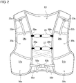
- Fig. 2 is an external view of the backpack 100 as seen from the front side.
- a first catch 36a and a second catch 36b are attached to an upper portion so as to be opposed to each other, and a third catch 38a and a fourth catch 38b are attached to a lower portion so as to be opposed to each other.
- the upper chest strap 35 and the lower chest strap 37 are formed of an elastic material, for example, a synthetic resin coated with synthetic fibers such as a bungee cord.
- the fifth catch 53a and the sixth catch 53b are attached to the exposed distal ends of the right auxiliary strap 52a and the left auxiliary strap 52b, respectively. These catches are connected to each other, so that positions of the right auxiliary strap 52a and the left auxiliary strap 52b are fixed, and a close contact state of the right side belt 50a and the left side belt 50b with the side is maintained.
- the fifth catch 53a and the sixth catch 53b also serve as the length adjusting members of the right auxiliary strap 52a and the left auxiliary strap 52b, respectively, and it is possible to adjust the length and fastening of each strap by pulling each strap to adjust a length of a distal end portion folded back of the right auxiliary strap 52a and the left auxiliary strap 52b.
- Fig. 3 illustrates an arrangement example of the fastening strap 32 and the auxiliary strap 52.
- each strap a portion other than the distal end exposed to the outside is arranged inside the fabric of the outer surface and does not appear in appearance, but in order to illustrate the arrangement of the strap, the strap is drawn on the outer surface of the backpack for convenience in this drawing.
- the right fastening strap 32a passes through a right chest, the right shoulder, and the center of the back of the wearer along the right shoulder belt 30a, and is sewn to be secured to a first locking point 70 in the vicinity of a lower left portion of the back.
- the left fastening strap 32b passes through a left chest, the left shoulder, and the center of the back of the wearer along the left shoulder belt 30b, and is sewn to be secured to a second locking point 71 in the vicinity of a lower right portion of the back.
- the first locking point 70 and the second locking point 71 are positions at a lower right corner and a lower left corner inside the housing 12, respectively, and are positions about 2/3 from the top of the main body 10.
- the right fastening strap 32a and the left fastening strap 32b intersect at a center point 72 at the center of the back.
- the right fastening strap 32a and the left fastening strap 32b bias a housed object 60 under the straps toward the back of the wearer in the housing 12 around the center point 72 where they intersect.
- the right auxiliary strap 52a passes from the right side of the wearer through the lower portion of the main body 10 along the right side belt 50a, and is sewn to be secured to a third locking point 73 in the vicinity of the lower left portion of the back.
- the left auxiliary strap 52b passes from the left side of the wearer through the lower portion of the main body 10 along the left side belt 50b, and is sewn to be secured to a fourth locking point 74 in the vicinity of the lower right portion of the back.
- Positions of the third locking point 73 and the fourth locking point 74 are in the vicinity of portions immediately below the first locking point 70 and the second locking point 71, respectively, and are positions about 2/3 from the top of the main body 10.
- the right auxiliary strap 52a and the left auxiliary strap 52b intersect at a center point 75 in the lower portion of the main body 10.
- a reinforcing strap 55 formed of the same non-elastic tape-shaped material as that of the fastening strap 32 is attached, and both ends thereof are sewn to the third locking point 73 and the fourth locking point 74, respectively.
- the reinforcing strap 55 is attached for maintaining a lateral width and a shape of the main body 10.
- a reinforcing material such as a resin for more firmly maintaining the lateral width and shape of the main body 10 may be attached.
- the housing 12 is provided at a position above the third locking point 73 and the fourth locking point 74 in the main body 10, and a position where the reinforcing strap 55 is attached and a portion where the right auxiliary strap 52a and the left auxiliary strap 52b intersect are sites that do not form a part of the housing 12. Therefore, the two auxiliary straps 52 do not have a function of biasing the housed object unlike the right fastening strap 32a and the left fastening strap 32b.
- a housing may be provided also in the lower portion of the main body 10, and the housed object may be biased toward the back by the two intersecting auxiliary straps 52.
- the two auxiliary straps 52 may be provided so as to be parallel without intersecting.
- Fig. 4 illustrates a biasing direction of the strap in a use state of the backpack.
- Four straps of the right fastening strap 32a, the left fastening strap 32b, the right auxiliary strap 52a, and the left auxiliary strap 52b are attached to the backpack 100.
- a portion other than the distal end exposed to the outside is arranged inside the fabric of the outer surface and does not appear in appearance especially as seen from the back side, but in order to illustrate the biasing direction of the strap, the strap arrangement is drawn on the outer surface of the backpack for convenience in the drawing.
- the wearer may fasten the right fastening strap 32a by pulling a distal end of the right fastening strap 32a exposed in the vicinity of the right chest on the front side in a first direction 62a from the back side toward the right chest beyond the top of the right shoulder (that is, by adjusting the fastening length).
- the wearer may fasten the left fastening strap 32b by pulling a distal end of the left fastening strap 32b exposed in the vicinity of the left chest on the front side in a second direction 62b from the back side toward the left chest beyond the top of the left shoulder (that is, by adjusting the fastening length).
- the right fastening strap 32a and the left fastening strap 32b bias the housed object 60 in a biasing direction 64, which is the direction from a rear side toward the back, at the center portion of the back where they intersect, so that it is possible to suppress the housed object 60 from separating from the back and to suppress the housed object 60 from swinging. It is also possible to suppress the entire main body 10 from separating from the back of the wearer, and to suppress the entire main body 10 from swinging. By suppressing the baggage and the entire main body 10 from swinging, it is possible to reduce a phase difference between a motion of the wearer during running and the swinging of the housed object 60 and the main body 10.
- the fastening length may be appropriately adjusted according to a size and a capacity of the housed object 60
- the housed object 60 may be appropriately biased in the biasing direction 64. That is, an appropriate fastening degree may be provided to the housed object 60.
- the fastening strap 32 so as to be pulled over the shoulder, there also is an effect that the center of gravity of the baggage may be lifted upward and kept at a high position.
- the wearer may fasten the right auxiliary strap 52a by pulling a distal end of the right auxiliary strap 52a exposed in the vicinity of the right side on the front side in a third direction 63a from the back through the right side toward the front side.
- the wearer may fasten the left auxiliary strap 52b by pulling a distal end of the left auxiliary strap 52b exposed in the vicinity of the left side on the front side in a fourth direction 63b from the back through the left side toward the front side.
- the distal ends of the right auxiliary strap 52a and the left auxiliary strap 52b are connected to each other with the fifth catch 53a and the sixth catch 53b, so that their respective pulling states are maintained.
- the right auxiliary strap 52a and the left auxiliary strap 52b bias the lower portion of the main body 10 in the biasing direction 64, which is the direction from the rear side toward the back, so that it is possible to suppress the main body 10 and the right and left side belts 50 from separating from the back and side of the wearer and to suppress the entire main body 10 from swinging.
- a tenth rib is at a lowermost end of a costal arch, which is a portion corresponding to the side. If a lower end of the side belt 50 is located above the tenth rib, a longitudinal width of the entire main body 10 is reduced accordingly, and the capacity of the housing 12 is also reduced, so that a housing capacity, which is an original function as the backpack, might be reduced. In contrast, when the lower end of the side belt 50 is located below the tenth rib, a fitting property of the side belt 50 to the side is impaired, and the swinging of the main body 10 might be large.
- both the capacity of the housing 12 and the fitting property of the main body 10 may be secured
- Fig. 5 illustrates a stacked structure of the main body 10.
- a first layer 20, a second layer 21, a third layer 22, and a fourth layer 23 are stacked in this order from a surface side toward a rear side.
- the first layer 20 on an outermost surface is elastic fabric made of synthetic fibers such as polyester and nylon, and is provided with the fastener 14 for opening and closing a slit-shaped opening for taking the baggage in and out of the housing 12 at both edges of the opening.
- the intersecting right and left fastening straps 32a and 32b and the intersecting right and left auxiliary straps 52a and 52b are overlapped.
- a liner 18 forming the inner surface of the housing 12 is overlapped.
- the liner 18 has such a longitudinal length that overlaps with the intersecting right and left fastening straps 32a and 32b, but does not overlap with the right and left auxiliary straps 52a and 52b.
- the liner 18 is provided with a first inner pocket 19a and a second inner pocket 19b that serve as pockets for a carried article.
- a housing position of the carried article housed in the first inner pocket 19a and the second inner pocket 19b is maintained as long as this is housed in the pocket, and the carried article may continuously receive a biasing force from the intersecting right and left fastening straps 32a and 32b, so that swinging is especially easily suppressed.
- a lining 24 that is mesh fabric of synthetic fibers is overlapped.
- a space formed by overlapping the first layer 20 and the third layer 22 and sewing the peripheries thereof together serves as the housing 12 in which the baggage may be housed.
- a space formed by overlapping the third layer 22 and the fourth layer 23 and sewing peripheries thereof together may mainly house a hydration system.
- the right auxiliary strap 52a and the left auxiliary strap 52b are arranged in a space obtained by overlapping the first layer 20 and the lining 24. Note that, on the lining 24, a band-shaped mesh material is sewn along an ideal arrangement route in design of the right auxiliary strap 52a and the left auxiliary strap 52b to form a tubular passage, and the right auxiliary strap 52a and the left auxiliary strap 52b are allowed to pass through the passage.
- the right auxiliary strap 52a and the left auxiliary strap 52b may be freely pulled in a direction from the back side to the front side through the vicinity of the side in the passage.
- a four-layer stacked structure is described as an example with reference to the drawing, the number of layers is not limited to four, and a stacked structure of three or fewer layers in which some layers are omitted, and a stacked structure of five or more layers in which additional layers are provided are also possible.
- a fourth layer may be a lining
- a fifth layer may be mesh fabric
- a space formed by overlapping the fourth layer and the fifth layer and sewing peripheries thereof together may house a hydration system.
- This embodiment is different from the first embodiment in that a different structure is adopted as a right fastening strap 32a and a left fastening strap 32b and is common in other configurations.
- a different structure is adopted as a right fastening strap 32a and a left fastening strap 32b and is common in other configurations.
- the difference is mainly described, and description of common points is omitted.
- FIG. 6 illustrates a structure of a fastening strap 32 in a second embodiment.
- a right fastening strap 32a passes from a right chest to a right shoulder of a wearer along a right shoulder belt 30a, and is coupled to a first biasing belt 40a at a portion where the right shoulder belt 30a is connected to a main body 10.
- the first biasing belt 40a is coupled to the right fastening strap 32a at a first coupling point 76 in an upper right portion of the main body 10, passes through a center point 72 at the center of a back, and is sewn to be secured to a first locking point 70 in the vicinity of a lower left portion of the back.
- a left fastening strap 32b passes from a left chest to a left shoulder of the wearer along a left shoulder belt 30b, and is coupled to a second biasing belt 40b at a portion where the left shoulder belt 30b is connected to the main body 10.
- the second biasing belt 40b is coupled to the left fastening strap 32b at a second coupling point 77 in an upper left portion of the main body 10, passes through the center point 72 at the center of the back, and is sewn to be secured to a second locking point 71 in the vicinity of a lower right portion of the back.
- the first biasing belt 40a and the second biasing belt 40b are formed of synthetic fibers such as nylon as a non-elastic tape-shaped material having a width of 3 cm to 6 cm, for example. Note that, in a variation, a material having elasticity to the extent that a biasing force is not impaired may be used as the biasing belt 40.
- the first biasing belt 40a and the second biasing belt 40b intersect at the center point 72 at the center of the back.
- the first biasing belt 40a and the second biasing belt 40b bias a housed object 60 under the two biasing belts intersecting in the housing 12 toward the back of the wearer around the center point 72 where they intersect.
- the first biasing belt 40a and the second biasing belt 40b are formed to be wider than the right fastening strap 32a and the left fastening strap 32b, respectively, so that the housed object 60 may be stably biased accordingly.
- the first biasing belt 40a and the second biasing belt 40b are formed separately, they may be connected by being sewn to each other and the like at the center point 72 in a variation.
- This embodiment is different from the first and second embodiments in that a different structure is adopted as a fastening strap 32 and a biasing belt 40 and is common in other configurations.
- a different structure is adopted as a fastening strap 32 and a biasing belt 40 and is common in other configurations.
- the difference is mainly described, and description of common points is omitted.
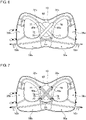
- Fig. 7 illustrates a structure of a fastening strap 32 and a biasing belt 40 in a third embodiment.
- This embodiment has a structure in which the fastening strap 32 in the first embodiment and the biasing belt 40 in the second embodiment are used in combination. That is, a right fastening strap 32a passes through a right chest, a right shoulder, and a center point 72 at the center of a back of a wearer along a right shoulder belt 30a, and is sewn to be directly secured to a first locking point 70 in the vicinity of a lower left portion of the back.
- a left fastening strap 32b passes through a left chest, a left shoulder, and the center point 72 at the center of the back of the wearer along a left shoulder belt 30b, and is sewn to be directly secured to a second locking point 71 in the vicinity of a lower right portion of the back.
- a first biasing belt 40a is provided below the right fastening strap 32a, and the first biasing belt 40a is attached to the right fastening strap 32a at a first coupling point 76 in an upper right portion and a fourth coupling point 79 at a lower left portion of a main body 10.
- a second biasing belt 40b is provided below the left fastening strap 32b, and the second biasing belt 40b is attached to the left fastening strap 32b at a second coupling point 77 in an upper left portion and a third coupling point 78 at a lower right portion of the main body 10.
- the first biasing belt 40a and the second biasing belt 40b are formed of synthetic fibers such as nylon as a non-elastic tape-shaped material having a width of 3 cm to 6 cm, for example. Note that, in a variation, a material having elasticity to the extent that a biasing force is not impaired may be used as the biasing belt 40.
- the first biasing belt 40a and the second biasing belt 40b may be formed to be detachable from the right fastening strap 32a and the left fastening strap 32b, respectively.
- a combination of the right fastening strap 32a and the first biasing belt 40a and a combination of the left fastening strap 32b and the second biasing belt 40b intersect at the center point 72 at the center of the back.
- the combination of the right fastening strap 32a and the first biasing belt 40a and the combination of the left fastening strap 32b and the second biasing belt 40b bias a housed object 60 under the biasing belt 40 in a housing 12 toward the back of the wearer around the center point 72 where they intersect.
- the housed object 60 may be stably biased accordingly, and furthermore, the housed object 60 may be more stably biased with a higher fastening strength by the right fastening strap 32a and the left fastening strap 32b.
- This embodiment is different from the third embodiment in that an auxiliary fabric material is used in place of the biasing belt 40 in the third embodiment.
- Other configurations are common to those of the third embodiment. Hereinafter, the difference is mainly described, and description of common points is omitted.
- Fig. 8 illustrates a structure of a fastening strap 32 and an auxiliary fabric material in a fourth embodiment.
- an auxiliary fabric material 41 is attached instead of attaching the biasing belt 40 of the third embodiment to the fastening strap 32.
- the auxiliary fabric material 41 is a planar fabric member having an area capable of entirely covering a housed object 60, and is attached to a right fastening strap 32a at a first coupling point 76 in an upper right portion and a fourth coupling point 79 in a lower left portion of a main body 10, and is attached to a left fastening strap 32b at a second coupling point 77 in an upper left portion and a third coupling point 78 in a lower right portion of the main body 10.
- a size of the auxiliary fabric material 41 is substantially the same as or slightly smaller than an inner diameter of a housing 12. Note that, the auxiliary fabric material 41 is attached to the fastening strap 32 so as to be detachable from the fastening strap 32.
- This embodiment is different from the fourth embodiment in that a small auxiliary fabric material is used in place of the auxiliary fabric material 41 in the fourth embodiment.
- Other configurations are common to those of the fourth embodiment. Hereinafter, the difference is mainly described, and description of common points is omitted.
- Fig. 9 illustrates a structure of a fastening strap 32 and a small auxiliary fabric material in a fifth embodiment.
- a small auxiliary fabric material 43 is attached instead of attaching the auxiliary fabric material 41 of the fourth embodiment to the fastening strap 32.
- the small auxiliary fabric material 43 is a planar fabric member smaller than the auxiliary fabric material 41 and having an area capable of covering only the vicinity of the center of a housed object 60.
- the small auxiliary fabric material 43 is attached to a right fastening strap 32a at a first coupling point 76 in an upper right portion and a fourth coupling point 79 in a lower left portion, and is attached to a left fastening strap 32b at a second coupling point 77 in an upper left portion and a third coupling point 78 in a lower right portion.
- the small auxiliary fabric material 43 has a size of, for example, 5 cm x 5 cm square. Note that, the small auxiliary fabric material 43 is attached to the fastening strap 32 so as to be detachable from the fastening strap 32.
- This embodiment is different from the second embodiment in that a plurality of biasing straps is used in place of the biasing belt 40 in the second embodiment.
- Other configurations are common to those of the second embodiment. Hereinafter, the difference is mainly described, and description of common points is omitted.
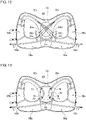
- Fig. 10 illustrates a structure of a fastening strap 32 and a biasing strap in a sixth embodiment.
- a plurality of biasing straps 42 is attached instead of attaching the biasing belt 40 of the second embodiment to the fastening strap 32. That is, one end of the fastening strap 32 is indirectly secured to a main body 10 via the plurality of biasing straps 42.
- the biasing strap 42 is a strap narrower than the fastening strap 32, it is possible to apply a biasing force to a housed object 60 over a wider range than that with the fastening strap 32 by using a plurality of them.
- a first biasing strap 42a and a second biasing strap 42b are attached to a right fastening strap 32a at a fifth coupling point 80 in an upper right portion, and sewn to be secured to a first locking portion 82a and a second locking portion 82b in a lower left portion.
- a third biasing strap 42c and a fourth biasing strap 42d are attached to a left fastening strap 32b at a sixth coupling point 81 in an upper left portion, and sewn to be secured to a third locking portion 82c and a fourth locking portion 82d in a lower right portion.
- This embodiment is different from the sixth embodiment in using three biasing straps in place of the two biasing straps in the sixth embodiment.
- Other configurations are common to those of the sixth embodiment.
- the difference is mainly described, and description of common points is omitted.
- Fig. 11 illustrates a structure of a fastening strap 32 and a biasing strap in a seventh embodiment.
- three biasing straps 42 are attached to the fastening strap 32.
- the biasing strap 42 is a strap narrower than the fastening strap 32, the larger the number of them to be used, the wider a range in which they may apply a biasing force to a housed object 60.
- a fifth biasing strap 42e, a sixth biasing strap 42f, and a seventh biasing strap 42g are attached to a right fastening strap 32a at a fifth coupling point 80 in an upper right portion, and sewn to be secured at a fifth locking portion 82e, a sixth locking portion 82f, and a seventh locking portion 82g, respectively, in a lower left portion.
- An eighth biasing strap 42h, a ninth biasing strap 42i, and a tenth biasing strap 42j are attached to a left fastening strap 32b at a sixth coupling point 81 in an upper left portion, and sewn to be secured at an eighth locking portion 82h, a ninth locking portion 82i, and a tenth locking portion 82j, respectively, in a lower right portion.
- a mesh-shaped member obtained by braiding a large number of straps in various patterns may be formed.
- This embodiment is different from the seventh embodiment in using a fastening strap 32 obtained by bundling three straps in place of the fastening strap 32 and the three biasing straps 42 in the seventh embodiment.
- Other configurations are common to those of the seventh embodiment. Hereinafter, the difference is mainly described, and description of common points is omitted.
- Fig. 12 illustrates a structure of a fastening strap 32 in an eighth embodiment.
- three straps are bundled to form one fastening strap 32.
- a portion from a shoulder to a front side of a right fastening strap 32a is fixedly bundled into one, and a distal end thereof is exposed to the outside on the front side.
- a portion from the shoulder through a back to a lower left portion of a main body 10 of the right fastening strap 32a is separated into three straps, and respective ends are secured to the lower left portion of the main body 10 by a first variable catch 83a, a second variable catch 83b, and a third variable catch 83c.
- a portion from a shoulder to a front side of a left fastening strap 32b is fixedly bundled into one, and a distal end thereof is exposed to the outside on the front side.
- a portion from a shoulder through the back to a lower right portion of the main body 10 of the left fastening strap 32b is separated into three straps, and respective ends are secured to the lower right portion of the main body 10 by a fourth variable catch 83d, a fifth variable catch 83e, and a sixth variable catch 83f.
- Positions at which the six variable catches 83 secure may be determined to any positions in a vertical direction, and arrangement and an interval thereof may be adjusted. For example, when the interval is increased, a housed object 60 may be stably biased over a wide range, and conversely, when the interval is decreased, the vicinity of the center of the housed object 60 may be intensively biased.
- this embodiment describes an example in which the three straps are bundled to form one fastening strap 32.
- two straps may be bundled to form one fastening strap 32, or four or more straps may be bundled to form one fastening strap 32.
- This embodiment is common to the fourth embodiment in using an auxiliary fabric material 41, but is different from the fourth embodiment in that two fastening straps 32 do not intersect. Other configurations are common to those of the fourth embodiment. Hereinafter, the difference is mainly described, and description of common points is omitted.
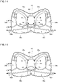
- Fig. 13 illustrates a structure of a fastening strap 32 and an auxiliary fabric material 41 in a ninth embodiment.
- two fastening straps 32 are not intersected to be secured to right and left diagonal positions, but the two fastening straps 32 are secured on the same side of right and left sides via the auxiliary fabric material 41. That is, a right fastening strap 32a passes through a first coupling point 76 in an upper right portion and a third coupling point 78 in a lower right portion of the auxiliary fabric material 41 to be secured to a second locking point 71 in a lower right portion of a housing 12.
- a left fastening strap 32b passes through a second coupling point 77 in an upper left portion and a second coupling point 77 in a lower left portion of the auxiliary fabric material 41 to be secured to a first locking point 70.
- the two fastening straps 32 are indirectly secured to a main body 10 via the auxiliary fabric material 41, a structure in which the right fastening strap 32a is secured on the right side and the left fastening strap 32b is secured on the left side without intersecting is also possible.
- the auxiliary fabric material 41 is pulled rightward and leftward, so that an area of a portion brought into contact with a housed object 60 is expanded and maximized. Accordingly, the housed object 60 may be more stably biased over a wide range.
- the auxiliary fabric material 41 is coupled to the fastening strap 32 so as to be detachable from the fastening strap 32.
- This embodiment is common to the fourth and ninth embodiments in using an auxiliary fabric material 41, but is different from the fourth and ninth embodiments in using four fastening straps 32 to couple to four corners of the auxiliary fabric material 41.
- Other configurations are common to those of the fourth and ninth embodiments. Hereinafter, the difference is mainly described, and description of common points is omitted.
- Fig. 14 illustrates a structure of a fastening strap 32 and an auxiliary fabric material 41 in a tenth embodiment.
- two fastening straps 32 are not intersected to be secured to right and left diagonal positions, but four fastening straps 32 are coupled to four corners of the auxiliary fabric material 41.
- a right fastening strap 32a is coupled to a first coupling point 76 in an upper right portion of the auxiliary fabric material 41
- a left fastening strap 32b is coupled to a second coupling point 77 in an upper left portion of the auxiliary fabric material 41.
- a lower right strap 32d is coupled to a lower right portion of the auxiliary fabric material 41
- a lower left strap 32c is coupled to a lower left portion of the auxiliary fabric material 41.
- One end of the lower right strap 32d is coupled to a third coupling point 78 in the lower right portion of the auxiliary fabric material 41, and the other end is secured to a second locking point 71.
- One end of the lower left strap 32c is coupled to a fourth coupling point 79 in the lower left portion of the auxiliary fabric material 41, and the other end is secured to a first locking point 70.
- one end of the right fastening strap 32a is indirectly secured to a main body 10 via the auxiliary fabric material 41 and the lower left strap 32c
- one end of the left fastening strap 32b is also indirectly secured to the main body 10 via the auxiliary fabric material 41 and the lower right strap 32d.
- the right fastening strap 32a is pulled, the upper right portion of the auxiliary fabric material 41 is pulled in a direction toward a right shoulder, and when the left fastening strap 32b is pulled, the upper left portion of the auxiliary fabric material 41 is pulled in a direction toward a left shoulder.
- the housed object 60 may be more stably biased over a wide range.
- fabric having a size capable of covering a major part of the housed object 60 is used as the auxiliary fabric material 41 in this embodiment, in a variation, fabric having a size enough to cover only the vicinity of the center portion of the housed object 60 as the small auxiliary fabric material 43 in the fifth embodiment may be used.
- This embodiment is common to the fourth and ninth embodiments in that an auxiliary fabric material 41 is used and two fastening straps 32 are used, and is common to the tenth embodiment in that an upper portion of the auxiliary fabric material 41 is coupled to the two fastening straps 32.
- this is different from the fourth, ninth, and tenth embodiments in that a part of the auxiliary fabric material 41 is directly secured to a lower portion of a housing 12, that is, the two fastening straps 32 are indirectly secured to the housing 12.
- Other configurations are common to those of the fourth, ninth, and tenth embodiments. Hereinafter, the difference is mainly described, and description of common points is omitted.
- Fig. 15 illustrates a structure of a fastening strap 32 and an auxiliary fabric material 41 in an eleventh embodiment.
- the auxiliary fabric material 41 in this embodiment an upper right portion is coupled to a right fastening strap 32a, and an upper left portion is coupled to a left fastening strap 32b.
- the auxiliary fabric material 41 has a shape in which a lower right corner and a lower left corner extend in a band shape in such a manner that a lower right portion is secured to a second locking point 71 and a lower left portion is secured to a first locking point 70. That is, one end of the fastening strap 32 is indirectly secured to a main body 10 via the auxiliary fabric material 41.
- the auxiliary fabric material 41 may be secured to a lower right portion and a lower left portion of a housing 12 without using the lower left strap 32c and the lower right strap 32d in the tenth embodiment.
- the upper right portion of the auxiliary fabric material 41 is pulled in a direction toward a right shoulder
- a left fastening strap 32b is pulled, the upper left portion of the auxiliary fabric material 41 is pulled in a direction toward a left shoulder.
- auxiliary fabric material 41 Since positions of the lower right portion and the lower left portion of the auxiliary fabric material 41 are fixed, an area of a portion brought into contact with a housed object 60 of the auxiliary fabric material 41 is enlarged and maximized by the pulling of the upper portion rightward and leftward. Accordingly, the housed object 60 may be more stably biased over a wide range. Note that, in a variation, a part of or an entire lower side or a part of or entire both sides of the auxiliary fabric material 41 may be sewn to be secured to the housing 12 by a shape different from that of the auxiliary fabric material 41 in the eleventh embodiment.
- This embodiment is common to the first and third to fifth embodiments in that two fastening straps 32 are intersected, but is different from the first and third to fifth embodiments in that a lower end of the fastening strap 32 is secured not inside but outside a housing 12, that is, outside a main body 10.
- Other configurations are common to those of the first and third to fifth embodiments. Hereinafter, the difference is mainly described, and description of common points is omitted.
- Fig. 16 illustrates arrangement and a structure of a fastening strap 32 in a twelfth embodiment. They are common to those of the first and third to fifth embodiments in that lower ends of intersecting right fastening strap 32a and left fastening strap 32b are attached to a lower right position and a lower left position of the housing 12, respectively. Note that, in this embodiment, the lower ends of the right fastening strap 32a and the left fastening strap 32b are exposed to the outside via strap holes 45a and 45b, respectively, and are secured to the outside of a main body 10.
- the strap hole 45a is provided at a position away from an outer edge of the main body 10 by about 5 cm to 10 cm on a route through which the right fastening strap 32a passes.
- the strap hole 45b is also provided in a position away from the outer edge of the main body 10 by about 5 cm to 10 cm on a route through which the left fastening strap 32b passes. Between the outer edge of the main body 10 and the strap hole 45a or 45b, a space in which a rod-shaped object or a cylindrical object may be interposed is generated, and the rod-shaped object or the cylindrical object may be allowed to pass to be interposed between the lower end of the fastening strap 32 and an outer surface of the main body 10. For example, a folded trail running pole or trekking pole as illustrated or a drink bottle may be allowed to pass between the fastening strap 32 and the outer surface of the main body 10.
- the pole and bottle When the fastening strap 32 is pulled with these pole and bottle interposed by the fastening strap 32, the pole and bottle may be firmly fixed. In this case, not only swinging of a housed object inside a housing 12 but also swinging of the pole and bottle may be suppressed at the same time, and swinging of an entire main body 10 may be suppressed.
- This embodiment is different from the first to twelfth embodiments in that a plurality of straps is used to form one auxiliary strap 52.
- Other configurations are common to those of the first to twelfth embodiments. Hereinafter, the difference is mainly described, and description of common points is omitted.
- Fig. 17 illustrates arrangement and a structure of an auxiliary strap 52 in a thirteenth embodiment.
- One end of each of a first auxiliary strap 52c, a second auxiliary strap 52d, and a third auxiliary strap 52e is secured to a third locking point 73 in an upper left portion of a lower portion of a main body 10, they pass through the inside of a right side belt 50a, and the other end of each of them is exposed to the outside from an opening provided at a distal end of the right side belt 50a.
- each of a fourth auxiliary strap 52f, a fifth auxiliary strap 52g, and a sixth auxiliary strap 52h is secured to a fourth locking point 74 in an upper right portion of the lower portion of the main body 10, they pass through the inside of a left side belt 50b, and the other end of each of them is exposed to the outside from an opening provided at a distal end of the left side belt 50b.
- the number of openings provided at the distal end of the side belt 50 may be the same as the number of auxiliary straps 52, or the opening may have a size corresponding to the number of auxiliary straps 52.
- this embodiment describes an example in which three straps are used to form one auxiliary strap 52.
- two straps may be used to form one auxiliary strap 52, or four or more straps may be used to form one auxiliary strap 52.
- This embodiment is common to the thirteenth embodiment in using a plurality of straps to form one auxiliary strap 52 but is different from the thirteenth embodiment in a bundled structure.
- Other configurations are common to those of the thirteenth embodiment.
- the difference is mainly described, and description of common points is omitted.
- Fig. 18 illustrates arrangement and a structure of an auxiliary strap 52 in a fourteenth embodiment.
- a distal end portion of the auxiliary strap 52 exposed from a hole at a distal end of a side belt 50 is one strap, and is branched from one strap into a plurality of straps inside the side belt 50.
- a plurality of auxiliary straps is bundled inside the side belt 50 and exposed to the outside as one auxiliary strap 52.
- a distal end of a right auxiliary strap 52a is exposed as one auxiliary strap 52 from a right side belt 50a, and the other end side is in such a form that three straps of a first auxiliary strap 52c, a second auxiliary strap 52d, and a third auxiliary strap 52e are bundled to be coupled to the right auxiliary strap 52a.
- the first auxiliary strap 52c, the second auxiliary strap 52d, and the third auxiliary strap 52e are secured to a lower left edge of a main body 10 by a first variable catch 83a, a second variable catch 83b, and a third variable catch 83c, respectively.
- a distal end of a left auxiliary strap 52b is exposed as one auxiliary strap 52 from a left side belt 50b, and the other end side is in such a form that three straps of a fourth auxiliary strap 52f, a fifth auxiliary strap 52g, and a sixth auxiliary strap 52h are bundled to be coupled to the left auxiliary strap 52b.
- the fourth auxiliary strap 52f, the fifth auxiliary strap 52g, and the sixth auxiliary strap 52h are secured to a lower right edge of the main body 10 by a fourth variable catch 83d, a fifth variable catch 83e, and a sixth variable catch 83f, respectively.
- Positions at which the six variable catches 83 secure may be determined to any positions in a vertical direction, and arrangement and an interval thereof may be adjusted.
- this embodiment describes an example in which the three straps are bundled to be coupled to one auxiliary strap 52.
- two straps may be bundled to be coupled to one auxiliary strap 52, or four or more straps may be bundled to be coupled to one auxiliary strap 52.
- This embodiment is different from the first to fourteenth embodiments in using a catch for securing to a shoulder belt 30 in place of a cord stopper 33 in order to adjust a fastening length of a fastening strap 32.
- Other configurations are common to those of the first to fourteenth embodiments. Hereinafter, the difference is mainly described, and description of common points is omitted.
- FIG. 19 illustrates arrangement of a fastening strap 32 and a plurality of catches and a first use example in a fifteenth embodiment.
- a right shoulder belt 30a and a left shoulder belt 30b are provided with six catches, respectively, along opposing edges.
- the right shoulder belt 30a is provided with a first right catch 84a, a second right catch 84b, a third right catch 84c, a fourth right catch 84d, a fifth right catch 84e, and a sixth right catch 84f from above along the edge.
- the left shoulder belt 30b is provided with a first left catch 85a, a second left catch 85b, a third left catch 85c, a fourth left catch 85d, a fifth left catch 85e, and a sixth left catch 85f from above along the edge.
- a right strap side catch 86a is provided at a distal end of a right fastening strap 32a and this may be selectively secured to any of the first to sixth right catches 84a to 84f.
- the right strap side catch 86a and the first to sixth right catches 84a to 84f may be formed of a set of male/female connectors such as magnets, clips, and a hook-and-loop fastener, for example.
- a fastening length of the right fastening strap 32a may be made shorter as it is secured to an upper catch out of the first to sixth right catches 84a to 84f, and the fastening length of the right fastening strap 32a may be made longer as it is secured to a lower catch.
- a left strap side catch 86b is provided at a distal end of a left fastening strap 32b and this may be selectively secured to any of the first to sixth left catches 85a to 85f.
- the left strap side catch 86b and the first to sixth left catches 85a to 85f may also be formed of a set of male/female connectors such as magnets, clips, and a hook-and-loop fastener, for example.
- a fastening length of the left fastening strap 32b may be made shorter as it is secured to an upper catch out of the first to sixth left catches 84a to 84f, and the fastening length of the left fastening strap 32b may be made longer as it is secured to a lower catch.
- the "fastening length” refers to a length from a top of a shoulder to a distal end or a length of a portion exposed to a front side of the fastening strap 32; the longer the "fastening length", the higher a fastening strength of the fastening strap 32 and it is tight, and the shorter the "fastening length", the lower the fastening strength and it is loose.
- the right fastening strap 32a is in such a manner that the right strap side catch 86a is secured to the first right catch 84a on an uppermost stage, and the right fastening strap 32a has the shortest fastening length, that is, the loosest fastening strength.
- the left fastening strap 32b is in such a manner that the left strap side catch 86b is secured to the fourth left catch 85d on a fourth stage from above or a third stage from below, and the left fastening strap 32b is the third longest, that is, this has the third tightest fastening strength.
- a wearer may adjust the fastening lengths of the right and left fastening straps 32 separately by selecting the catch to which this is secured according to a situation such as a size and a shape of baggage and weight distribution in the housing 12. Especially, it is possible to adjust in stages as many as the catches arranged in a vertical direction, that is, in six stages in the example of this drawing.
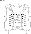
- Fig. 20 illustrates arrangement of the fastening strap 32 and a plurality of catches and a second use example in the fifteenth embodiment.
- This use example is the same as the first use example in the structure and arrangement of the fastening strap 32 and a plurality of catches, but is different from the first use example in that the right fastening strap 32a and the left fastening strap 32b are intersected on a front side to be secured to the catches. More specifically, the right strap side catch 86a at a distal end of the right fastening strap 32a is selectively secured not to a right shoulder belt 30a side but to any one of the first to sixth left catches 85a to 85f on a left shoulder belt 30b side on the opposite side.
- the left strap side catch 86b at a distal end of the left fastening strap 32b is selectively secured not to a left shoulder belt 30b side but to any one of the first to sixth right catches 84a to 84f on a right shoulder belt 30a side on the opposite side.
- the right strap side catch 86a of the right fastening strap 32a is secured to the fourth left catch 85d on the third stage from below on the left shoulder belt 30b side
- the left strap side catch 86b of the left fastening strap 32b is secured to the fourth right catch 84d on the third stage from below on the right shoulder belt 30a side.
- the right and left fastening straps 32 are elongated to the opposite side, so that fastening lengths become longer than those in a case where they are fastened to the catches on the same sides, and the fastening strength may be increased. Furthermore, since it may be adjusted in vertical six stages, respectively, so that it may be adjusted in total of 12 stages by adjusting vertically and laterally.
- This embodiment is different from the fifteenth embodiment in securing a distal end of a fastening strap 32 to another strap such as an auxiliary strap 52 in order to adjust a fastening length of the fastening strap 32.
- Other configurations are common to those of the first to fifteenth embodiments. Hereinafter, the difference is mainly described, and description of common points is omitted.
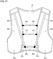
- Fig. 21 illustrates a first use example regarding a fastening strap 32 and a securing structure in a sixteenth embodiment.
- a strap side catch 86 at a distal end of the fastening strap 32 is hooked to be secured to an auxiliary strap 52.
- a right strap side catch 86a at a distal end of a right fastening strap 32a is hooked to a right auxiliary strap 52a, and a left strap side catch 86b at a distal end of a left fastening strap 32b is hooked to a left auxiliary strap 52b.
- a fastening length and fastening strength of the fastening strap 32 may be adjusted only by hooking to a strap in an existing shape. Since a position of the auxiliary strap 52 corresponds to a position of a catch on a lowermost stage such as the sixth right catch 84f or the sixth left catch 85f in the fifteenth embodiment, it is possible to increase the fastening length of the fastening strap 32 to a longest level and increase the fastening strength to a strongest level.
- Fig. 22 illustrates a second use example regarding the fastening strap 32 and the securing structure in the sixteenth embodiment.
- the second use example is different from the first use example in that the strap side catch 86 at the distal end of the fastening strap 32 is hooked not to the auxiliary strap 52 but to an upper chest strap 35 or a lower chest strap 37.
- the right strap side catch 86a at the distal end of the right fastening strap 32a is hooked to a lower right chest strap 37a
- the left strap side catch 86b at the distal end of the left fastening strap 32b is hooked to a lower left chest strap 37b.
- the fastening length of the fastening strap 32 may be made shorter than that in the first use example to loosen the fastening strength. Furthermore, when this is secured to an upper right chest strap 35a and an upper left chest strap 35b higher by one stage, the fastening length of the fastening strap 32 may be further shortened to loosen the fastening strength. In this manner, by hooking the fastening strap 32 to any one of the auxiliary strap 52, the lower chest strap 37, and the upper chest strap 35, the fastening length and the fastening strength may be adjusted in three stages.
- Fig. 23 illustrates a third use example regarding the fastening strap 32 and the securing structure in the sixteenth embodiment.
- the third use example is common to the first use example in that the strap side catch 86 of the fastening strap 32 is hooked to the auxiliary strap 52, but this use example is different in that the right fastening strap 32a and the left fastening strap 32b are intersected and hooked to the opposite sides. More specifically, the right strap side catch 86a of the right fastening strap 32a is hooked to the left auxiliary strap 52b on the left side, and the left strap side catch 86b of the left fastening strap 32b is hooked to the right auxiliary strap 52a on the right side.
- the right fastening strap 32a and the left fastening strap 32b intersect, so that the fastening length increases and the fastening strength increases accordingly.
- a method of allowing the right fastening strap 32a and the left fastening strap 32b to intersect may also be applied to a case where the strap side catch 86 is hooked to the upper chest strap 35 or the lower chest strap 37, and it is possible to increase the fastening length to adjust the fastening strength to be higher as compared with a case where this is hooked to the upper chest strap 35, the lower chest strap 37, and the auxiliary strap 52 without intersection.
- a total of six stages of adjustment may be performed by three stages of hooking positions and the presence of intersection.
- This embodiment is different from the first to fourteenth embodiments in using a predetermined dial fastening mechanism in order to adjust a fastening length of a fastening strap 32.
- Other configurations are common to those of the first to fourteenth embodiments. Hereinafter, the difference is mainly described, and description of common points is omitted.
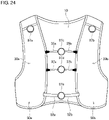
- Fig. 24 illustrates arrangement of a fastening strap 32 and a dial fastening mechanism in a seventeenth embodiment.
- a dial mechanism 87 is used in place of the cord stopper 33 in the first to fourteenth embodiments.
- the dial mechanism 87 is a mechanism capable of winding a wire by rotation of the dial and releasing a winding state only by pressing a central button once. This winding and releasing of the dial mechanism 87 implements pulling and releasing of the fastening strap 32.
- a right strap dial mechanism 87a and a wire thereof are attached to a distal end of a right fastening strap 32a, and a left strap dial mechanism 87b and a wire thereof are attached to a distal end of a left fastening strap 32b.
- the dial mechanism 87 is also used as a connector for an upper chest strap 35, a lower chest strap 37, and an auxiliary strap 52.
- An upper chest strap dial mechanism 87c is used to connect and fasten an upper right chest strap 35a and an upper left chest strap 35b
- a lower chest strap dial mechanism 87d is used to connect and fasten a lower right chest strap 37a and a lower left chest strap 37b.
- An auxiliary strap dial mechanism 87e is used to connect and fasten a right auxiliary strap 52a and a left auxiliary strap 52b.
- This embodiment is common to the first to seventeenth embodiments mainly in providing a fastening strap 32 in an upper portion of a main body 10 and an auxiliary strap 52 in a lower portion of the main body 10, but is different from the first to seventeenth embodiments in further providing an auxiliary strap in the upper portion of the main body 10.
- Other configurations are common to those of the first to seventeenth embodiments. Hereinafter, the difference is mainly described, and description of common points is omitted.
- Fig. 25 is an external view of an entire backpack 100 according to an eighteenth embodiment.
- a right chest auxiliary strap 56a and a left chest auxiliary strap 56b are provided in directions parallel with a right auxiliary strap 52a and a left auxiliary strap 52b, respectively.
- the right chest auxiliary strap 56a is arranged in parallel with the right auxiliary strap 52a from a main body 10 toward a front side through a right armpit above the right auxiliary strap 52a.
- the left chest auxiliary strap 56b is arranged in parallel with the left auxiliary strap 52b from the main body 10 toward the front side through a left armpit above the left auxiliary strap 52b.
- the right chest auxiliary strap 56a and the left chest auxiliary strap 56b are arranged so as to intersect in a housing 12 in the main body 10, exposed to the outside from holes provided under the right and left armpits toward the front side, pass through the inside of right and left shoulder belts 30a and 30b from holes on an extension line thereof, and distal ends thereof are exposed to the outside from holes on an extension line thereof.
- a seventh catch 53c and an eighth catch 53d are attached to the distal ends of the right chest auxiliary strap 56a and the left chest auxiliary strap 56b, respectively.
- Fig. 26 is an external view of the backpack 100 as seen from a front side according to the eighteenth embodiment.
- the right chest auxiliary strap 56a and the left chest auxiliary strap 56b are arranged so as to be horizontal at least on the front side at a height near the armpit or near a lower portion of a chest of the wearer.
- the distal ends of the right chest auxiliary strap 56a and the left chest auxiliary strap 56b are exposed to the outside at a position between the right shoulder belt 30a and the left shoulder belt 30b, and parts thereof are also exposed to the outside near the right and left armpits.
- the seventh catch 53c and the eighth catch 53d are attached to the exposed distal ends of the right chest auxiliary strap 56a and the left chest auxiliary strap 56b, respectively.
- the seventh catch 53c and the eighth catch 53d also serve as length adjusting members of the right chest auxiliary strap 56a and the left chest auxiliary strap 56b, respectively, and it is possible to adjust a length and fastening of each strap by pulling each strap to adjust a length of a distal end portion folded back of the right chest auxiliary strap 56a and the left chest auxiliary strap 56b.
- Fig. 27 illustrates an arrangement example of a fastening strap and an auxiliary strap in the eighteenth embodiment. Also in this drawing, a strap is drawn on an outer surface of the backpack for convenience to illustrate the arrangement of the strap.
- the illustrated arrangement of the fastening strap 32 and auxiliary strap 52 is similar to the configuration and arrangement in the first embodiment, but they may be replaced with the configuration and arrangement including the fastening strap 32 and the auxiliary strap 52 in the second to seventeenth embodiments.
- the right chest auxiliary strap 56a and the left chest auxiliary strap 56b are further arranged horizontally in the vicinity of the center in the upper portion of the main body 10.
- One end of the right chest auxiliary strap 56a is sewn to a fifth locking point 90, which is an edge on a left side of a center point 72 where the right fastening strap 32a and the left fastening strap 32b intersect in the housing 12, and is directly fixed to the main body 10.
- the right chest auxiliary strap 56a passes from the fifth locking point 90 through the center point 72 and is once exposed to the outside in the vicinity of the right armpit, and passes through the inside of the front side of the right shoulder belt 30a, then the distal end thereof is exposed to the outside on the front side.
- One end of the left chest auxiliary strap 56b is sewn to a sixth locking point 91, which is an edge on a right side of the center point 72 where the right fastening strap 32a and the left fastening strap 32b intersect in the housing 12, and is directly fixed to the main body 10.
- the left chest auxiliary strap 56b passes from the sixth locking point 91 through the center point 72 and is once exposed to the outside in the vicinity of the left armpit, and passes through the inside of the left shoulder belt 30b, then the distal end thereof is exposed to the outside on the front side.
- distal portions from inner passages of the right shoulder belt 30a and the left shoulder belt 30b may be pulled out rearward to be folded and stored in the housing 12 or fastened to the side of the main body 10 by a bungee cord and the like to be secured.
- a point where the right chest auxiliary strap 56a and the left chest auxiliary strap 56b intersect is designed to be at the same position as the center point 72 where the right fastening strap 32a and the left fastening strap 32b intersect. More specifically, the fifth locking point 90 and the sixth locking point 91 are provided at a position about 1/2 from the top in a longitudinal width of the upper portion of the main body 10 or the housing 12, or at a position about 1/3 from the top in the longitudinal width of the entire main body 10.
- the right chest auxiliary strap 56a and the left chest auxiliary strap 56b may be designed to intersect above the center point 72, or may be designed to intersect below the center point 72.
- the positions of the fifth locking point 90 and the sixth locking point 91 may be moved to a position above the illustrated position, for example, a position about 2/5 from the top in the longitudinal width of the main body 10, or a position below the illustrated position, for example, a position about 1/2 from the top in the longitudinal width of the main body 10.
- the housed object 60 may be supported at two points of the point where the right chest auxiliary strap 56a and the left chest auxiliary strap 56b intersect and the center point 72, and the biasing force may be applied in a distributed manner.
- the right chest auxiliary strap 56a and the left chest auxiliary strap 56b are intersected on an outer layer of the right fastening strap 32a and the left fastening strap 32b, but they may be intersected on an inner layer of the right fastening strap 32a and the left fastening strap 32b, that is, on a layer between the fastening strap 32 and the housed object 60.
- the fastening strap and the auxiliary strap pass through the inside of the shoulder belt and the side belt
- the belts may be exposed to the outside.
- the present invention mainly relates to a backpack used for trail running.
Landscapes
- Portable Outdoor Equipment (AREA)
Abstract
Description
- The present invention relates to a backpack. This especially relates to a backpack used for trail running.
- In trail running, a player needs to carry a backpack due to characteristics or regulations of game. A volume and weight of baggage to be housed in the backpack vary depending on a running distance, a replenishment condition and the like. The running distance in the game is often long, such as several tens of kilometers to a hundred and several tens of kilometers, and for ease of running and reduction of a burden on a body, a vest-type having a high degree of adhesion to the body is a mainstream, and its form is close to a garment. In order to increase the degree of adhesion to the body, one that tightly fasten a strap on a chest to adjust is known (refer to, for example, Patent Literature 1).
-
- [Patent Literature 1]
JP 2012-148036 A - [Patent Literature 2]
JP 4677513 B2 - However, even though a degree of adhesion of a backpack itself increases, when a housed object swings inside, the swinging is likely to propagate to an entire backpack, and thus this swinging might be felt by a wearer as the swinging of the backpack itself.
- The present invention is achieved in view of such a situation, and an object thereof is to provide a backpack that suppresses swinging of a housed object.
- In order to solve the above-described problem, a backpack according to an aspect of the present invention is provided with a main body including a housing, and a shoulder belt extending from an upper portion of the main body. A fastening strap that passes through an inside of a housing is attached to a main body in such a manner that a housed object is able to be biased toward a back of a wearer in the housing, the fastening strap is arranged in such a manner that one end of which is directly or indirectly secured to a predetermined position in a lower portion of the housing, attached along the shoulder belt from the predetermined position through the inside of the housing, and the other end of which is located on a front side than a top of a shoulder of the wearer, and has a fastening length adjustable at a position on the front side of the wearer.
- According to the present invention, it is possible to provide a backpack that suppresses swinging of a housed object.
-
-
Fig. 1 is an external view of an entire backpack. -
Fig. 2 is an external view of the backpack as seen from a front side. -
Fig. 3 is a view illustrating an arrangement example of a fastening strap and an auxiliary strap. -
Fig. 4 is a view illustrating a biasing direction of the strap in a use state of the backpack. -
Fig. 5 is a view illustrating a stacked structure of a main body. -
Fig. 6 is a view illustrating a structure of a fastening strap in a second embodiment. -
Fig. 7 is a view illustrating a structure of a fastening strap and a biasing belt in a third embodiment. -
Fig. 8 is a view illustrating a structure of a fastening strap and an auxiliary fabric material in a fourth embodiment. -
Fig. 9 is a view illustrating a structure of a fastening strap and a small auxiliary fabric material in a fifth embodiment. -
Fig. 10 is a view illustrating a structure of a fastening strap and a biasing strap in a sixth embodiment. -
Fig. 11 is a view illustrating a structure of a fastening strap and a biasing strap in a seventh embodiment. -
Fig. 12 is a view illustrating a structure of a fastening strap in an eighth embodiment. -
Fig. 13 is a view illustrating a structure of a fastening strap and an auxiliary fabric material in a ninth embodiment. -
Fig. 14 is a view illustrating a structure of a fastening strap and an auxiliary fabric material in a tenth embodiment. -
Fig. 15 is a view illustrating a structure of a fastening strap and an auxiliary fabric material in an eleventh embodiment. -
Fig. 16 is a view illustrating arrangement and a structure of a fastening strap in a twelfth embodiment. -
Fig. 17 is a view illustrating arrangement and a structure of an auxiliary strap in a thirteenth embodiment. -
Fig. 18 is a view illustrating arrangement and a structure of an auxiliary strap in a fourteenth embodiment. -
Fig. 19 is a view illustrating arrangement of a fastening strap and a plurality of catches and a first use example in a fifteenth embodiment. -
Fig. 20 is a view illustrating arrangement of a fastening strap and a plurality of catches and a second use example in the fifteenth embodiment. -
Fig. 21 is a view illustrating a first use example regarding a fastening strap and a securing structure in a sixteenth embodiment. -
Fig. 22 is a view illustrating a second use example regarding the fastening strap and the securing structure in the sixteenth embodiment. -
Fig. 23 is a view illustrating a third use example regarding the fastening strap and the securing structure in the sixteenth embodiment. -
Fig. 24 is a view illustrating arrangement of a fastening strap and a dial fastening mechanism in a seventeenth embodiment. -
Fig. 25 is an external view of an entire backpack according to an eighteenth embodiment. -
Fig. 26 is an external view of the backpack as seen from a front side according to the eighteenth embodiment. -
Fig. 27 is a view illustrating an arrangement example of a fastening strap and an auxiliary strap in the eighteenth embodiment. - In this embodiment, a plurality of intersecting fastening straps and a plurality of intersecting auxiliary straps are provided in a main body of a backpack. The plurality of fastening straps and the plurality of auxiliary straps bias a housed object and the backpack main body toward a back of a wearer. This suppresses the housed object from swinging and suppresses an entire backpack from swinging when a backpack wearer runs.
-
Fig. 1 is an external view of the entire backpack. Abackpack 100 is provided with amain body 10, ashoulder belt 30, and aside belt 50. Thebackpack 100 in this embodiment is a backpack assumed to be mainly used in trail running, and is formed as a vest-type backpack that may be worn like a garment to increase a degree of adhesion to a body. Therefore, themain body 10, theshoulder belt 30, and theside belt 50 are continuously and integrally formed like one garment. Note that, an application of this backpack is not limited to trail running, and this may also be used for running in general. In addition, this may also be used in applications other than running, for example, as a backpack for carrying baggage in light mountain climbing such as highspeed hiking, fast packing, and trekking, or in daily life. Boundaries between themain body 10, theshoulder belt 30, and theside belt 50 are not strictly defined, and a boundary line does not appear in appearance, but an example of the boundary is illustrated as a guide. In the drawing, theshoulder belt 30 generally refers to a portion from a shoulder to a front body; for example, a portion fromfirst chain line 31a tosecond chain line 31b corresponds to aright shoulder belt 30a, and a portion fromthird chain line 31c tofourth chain line 31d corresponds to aleft shoulder belt 30b. Theside belt 50 generally refers to a portion brought into contact with a side and a waist; for example, a portion fromsecond chain line 31b tofifth chain line 31e corresponds to aright side belt 50a, and a portion fromfourth chain line 31d tosixth chain line 31f corresponds aleft side belt 50b. A remaining portion, for example, a portion surrounded byfirst chain line 31a,second chain line 31b,fifth chain line 31e, andsixth chain line 31f corresponds to themain body 10. Note that, in a variation, as in a typical backpack that is not a vest-type for trail running, at least one of themain body 10, theshoulder belt 30, and theside belt 50 may be formed separately from the other portions. For example, theshoulder belt 30 and theside belt 50 may be formed separately, and theshoulder belt 30 and theside belt 50 may be connected by a predetermined strap. Alternatively, it is also possible to form only of themain body 10 and theshoulder belt 30 without the side belt provided, and theshoulder belt 30 may be connected to a lower portion of themain body 10 by a predetermined strap. - The
main body 10 is a portion located on a back side of the wearer wearing thebackpack 100 on the body. Themain body 10 is formed by sewing edges together in a state in which a plurality of pieces of fabric is stacked, and includes ahousing 12 capable of housing baggage such as equipment and a carried article as a space between the stacked pieces of fabric. Afastener 14 that may be opened and closed in a vertical direction is provided at the center of an outer surface of themain body 10, and when thefastener 14 is opened, the carried article may be taken in and out of thehousing 12, which is an internal space. A length of thefastener 14 is about 2/3 of a length in the vertical direction of an entiremain body 10, and a size in the vertical direction of thehousing 12 is also about 2/3 of the length in the vertical direction of the entiremain body 10. Thehousing 12 is a main baggage space that occupies most of an upper portion volume of themain body 10, and has a larger capacity than other pockets and the like. Here, in a case where thebackpack 100 is used for trail running, it is desirable, when running, to keep the center of gravity at a high position in such a manner that heavy baggage is placed on the back as close as possible to a neck and shoulders rather than a low position close to hips. Therefore, thehousing 12 is provided in the upper portion of themain body 10 so that a major part of thehousing 12 occupies an upper half of themain body 10, and thehousing 12 has a structure not to continue to the lower portion, especially to a lowermost end of themain body 10, so that heavy baggage does not descend to a low position. - The
shoulder belt 30 is a belt-shaped portion continuously formed from the upper portion of themain body 10 toward a portion corresponding to the front body on a front side through a portion above the shoulder of the wearer, and includes theright shoulder belt 30a extending to a side of the right shoulder of the wearer and theleft shoulder belt 30b extending to a side of the left shoulder of the wearer. Theright shoulder belt 30a and theleft shoulder belt 30b are provided with aright chest pocket 34a and aleft chest pocket 34b, respectively, capable of housing a drink bottle, a soft flask and the like on the front side of the wearer. Anupper chest strap 35, afirst catch 36a, asecond catch 36b, alower chest strap 37, athird catch 38a, and afourth catch 38b are described with reference to a next drawing. - The
side belt 50 is a belt-shaped portion continuously formed from the lower portion of themain body 10 through a portion beside the side of the wearer toward the front side, and includes theright side belt 50a extending to a side of a right side of the wearer and theleft side belt 50b extending to a side of a left side of the wearer. Theright side belt 50a is provided with aright side pocket 54a, and theleft side belt 50b is provided with aleft side pocket 54b. An upper portion of a front side end of theright side belt 50a is continuously formed with theright shoulder belt 30a to be connected thereto. An upper portion of a front side end of theleft side belt 50b is continuously formed with theleft shoulder belt 30b to be connected thereto. - In this manner, the
main body 10, theshoulder belt 30, and theside belt 50 are continuously formed into an annular shape to form the vest-type backpack like a garment, and the wearer may wear thebackpack 100 like a garment by inserting both arms through a right armpassable portion 16a and a left armpassable portion 16b formed inside the annular portion. - A plurality of fastening straps 32 that passes through the inside of the
housing 12 is attached to themain body 10 in such a manner that the housed object may be biased toward the back of the wearer in thehousing 12. The fastening strap 32 is arranged in such a manner that one end of which is secured directly or indirectly to a predetermined position in the lower portion of thehousing 12, attached along theshoulder belt 30 from the predetermined position through the vicinity of the center in thehousing 12, and the other end of which is located on the front side than the top of the shoulder of the wearer. The fastening strap 32 is formed of aright fastening strap 32a and aleft fastening strap 32b. The fastening strap 32 is formed of a non-elastic tape-shaped material having a width of 1 cm to 3 cm, for example, synthetic fibers such as nylon. Note that, in a variation, a material having elasticity to the extent that a fastening state is not impaired may be used as the fastening strap 32. As illustrated in the drawing, theright fastening strap 32a and theleft fastening strap 32b in this embodiment intersect in the upper portion of themain body 10, especially inside thehousing 12 in the vicinity of the center position of an opening opened by thefastener 14. This intersection position corresponds to the center position of thehousing 12 provided in the upper portion of themain body 10, and is designed so that the intersection portion is brought into contact with the vicinity of the center of the baggage in thehousing 12. - The
right shoulder belt 30a and theleft shoulder belt 30b are formed in such a manner that at least a portion brought into contact with the shoulder is formed of a plurality of pieces of fabric overlapping with each other. In theright shoulder belt 30a and theleft shoulder belt 30b, a tubular passage formed between the pieces of fabric in each shoulder portion is continuous to thehousing 12, and theright fastening strap 32a and theleft fastening strap 32b are arranged so as to pass through the passages. Note that, the term "tubular" as used herein merely means that a state in which overlapping pieces of fabric are separated from each other may become the tubular passage, and usually, a state in which the pieces of fabric overlap with each other and the "tube" is folded is maintained. Theright fastening strap 32a is allowed to pass through the passage in theright shoulder belt 30a, and an upper end thereof is exposed to the outside from a front side opening of the passage. Theleft fastening strap 32b is allowed to pass through the passage in theleft shoulder belt 30b, and an upper end thereof is exposed to the outside from a front side opening of the passage. The passage in theshoulder belt 30 may be provided with a strap loop for securing the fastening strap 32 passing through the same onto a predetermined route to prevent positional displacement. Anti-slip treatment may be applied to the fastening strap 32. Aright cord stopper 33a and aleft cord stopper 33b for preventing returning to the passage in theshoulder belt 30 are attached to portions exposed to the outside of theright fastening strap 32a and theleft fastening strap 32b, respectively. Note that, in a variation, the fastening strap 32 may be arranged not in the inner passage of theshoulder belt 30 but on an outer surface of theshoulder belt 30 along the same. In this case, the outer surface of theshoulder belt 30 may be provided with a strap loop for securing the fastening strap 32 passing through the same onto a predetermined route to prevent positional displacement. - The
right fastening strap 32a and theleft fastening strap 32b are arranged so that both ends of each strap are diagonally located in thehousing 12, thereby intersecting in thehousing 12, and a plurality of intersecting fastening straps 32 may bias the housed object toward the back of the wearer in thehousing 12. A lower end of theright fastening strap 32a is directly secured, for example, by being sewn to a lower left position of thehousing 12, and a lower end of theleft fastening strap 32b is directly secured, for example, by being sewn to a lower right position of thehousing 12. Since theright fastening strap 32a and theleft fastening strap 32b are not fixed in thehousing 12 except the lower ends secured, the housed object may be interposed between the two intersecting straps 32 and an inner surface on the back side. Since the lower end of theright fastening strap 32a and the lower end of theleft fastening strap 32b are sewn to themain body 10 to be fixed in position, when an upper end of theright fastening strap 32a and an upper end of theleft fastening strap 32b are pulled downward on the front side, theright fastening strap 32a and theleft fastening strap 32b intersecting in thehousing 12 are tensioned, and the housed object may be biased toward the inner surface on the back side. The wearer may adjust a fastening length of the strap by fixing theright cord stopper 33a and theleft cord stopper 33b at any position after pulling theright fastening strap 32a and theleft fastening strap 32b. That is, it is possible to prevent a distal strap portion from the position at which the cord stopper 33 is fixed from returning from the front side into the tubular passage, and to maintain the fastening length of the strap and a biasing state in thehousing 12 of the housed object. - An
auxiliary strap 52 a fastening length of which is adjustable at a position on the front side of the wearer is attached to theside belt 50 along theside belt 50 from the lower portion of themain body 10 to the front side. The auxiliary strap 52 is formed of a rightauxiliary strap 52a and a leftauxiliary strap 52b. The auxiliary strap 52 is formed of an elastic tape-shaped material having a width of 1 cm to 3 cm, for example, synthetic fibers such as nylon in order to alleviate compression around the waist such as the side and abdominal. Note that, in a variation, a non-elastic tape-shaped material to the extent that the waist is not compressed too much may be used as the auxiliary strap 52. - The
right side belt 50a and theleft side belt 50b are formed of a plurality of pieces of fabric overlapping with each other. In theright side belt 50a and theleft side belt 50b, a tubular passage formed between the pieces of fabric is continuous to the lower portion of thehousing 12, and the rightauxiliary strap 52a and the leftauxiliary strap 52b are arranged so as to pass through the passages. They are arranged so that themain body 10 may be biased toward the back of the wearer in the lower portion of themain body 10 by adjusting the fastening lengths of the two auxiliary straps 52. That is, the two auxiliary straps 52 are arranged so that both ends of each of the auxiliary straps 52 are diagonally located in the lower portion of themain body 10, thereby intersecting at the center of the lower portion of themain body 10. One end of each of the two auxiliary straps 52 is secured to a predetermined position in the lower portion of themain body 10, and the other ends thereof are connected to each other via a length adjusting member at the position on the front side of the wearer interposed between the right andleft side belts 50. More specifically, the rightauxiliary strap 52a is allowed to pass through the passage in theright side belt 50a, and a distal end thereof is exposed to the outside from a front side hole of the passage. The leftauxiliary strap 52b is allowed to pass through the passage in theleft side belt 50b, and a distal end thereof is exposed to the outside from a front side hole of the passage. Afifth catch 53a and asixth catch 53b are attached as the length adjusting members to portions exposed to the outside of the rightauxiliary strap 52a and the leftauxiliary strap 52b, respectively. Thefifth catch 53a and thesixth catch 53b are buckles that may fix the adjusted strap lengths and be connected to each other. -
Fig. 2 is an external view of thebackpack 100 as seen from the front side. On theright shoulder belt 30a and theleft shoulder belt 30b, along edges opposed to each other when thebackpack 100 is worn, afirst catch 36a and asecond catch 36b are attached to an upper portion so as to be opposed to each other, and athird catch 38a and afourth catch 38b are attached to a lower portion so as to be opposed to each other. By hooking theupper chest strap 35 to thefirst catch 36a and thesecond catch 36b and hooking thelower chest strap 37 to thethird catch 38a and thefourth catch 38b, positions of theright shoulder belt 30a and theleft shoulder belt 30b in the worn state may be fixed. Theupper chest strap 35 and thelower chest strap 37 are formed of an elastic material, for example, a synthetic resin coated with synthetic fibers such as a bungee cord. - The
fifth catch 53a and thesixth catch 53b are attached to the exposed distal ends of the rightauxiliary strap 52a and the leftauxiliary strap 52b, respectively. These catches are connected to each other, so that positions of the rightauxiliary strap 52a and the leftauxiliary strap 52b are fixed, and a close contact state of theright side belt 50a and theleft side belt 50b with the side is maintained. Thefifth catch 53a and thesixth catch 53b also serve as the length adjusting members of the rightauxiliary strap 52a and the leftauxiliary strap 52b, respectively, and it is possible to adjust the length and fastening of each strap by pulling each strap to adjust a length of a distal end portion folded back of the rightauxiliary strap 52a and the leftauxiliary strap 52b. -
Fig. 3 illustrates an arrangement example of the fastening strap 32 and the auxiliary strap 52. In each strap, a portion other than the distal end exposed to the outside is arranged inside the fabric of the outer surface and does not appear in appearance, but in order to illustrate the arrangement of the strap, the strap is drawn on the outer surface of the backpack for convenience in this drawing. Theright fastening strap 32a passes through a right chest, the right shoulder, and the center of the back of the wearer along theright shoulder belt 30a, and is sewn to be secured to afirst locking point 70 in the vicinity of a lower left portion of the back. Theleft fastening strap 32b passes through a left chest, the left shoulder, and the center of the back of the wearer along theleft shoulder belt 30b, and is sewn to be secured to asecond locking point 71 in the vicinity of a lower right portion of the back. Thefirst locking point 70 and thesecond locking point 71 are positions at a lower right corner and a lower left corner inside thehousing 12, respectively, and are positions about 2/3 from the top of themain body 10. Theright fastening strap 32a and theleft fastening strap 32b intersect at acenter point 72 at the center of the back. Theright fastening strap 32a and theleft fastening strap 32b bias a housedobject 60 under the straps toward the back of the wearer in thehousing 12 around thecenter point 72 where they intersect. - The right
auxiliary strap 52a passes from the right side of the wearer through the lower portion of themain body 10 along theright side belt 50a, and is sewn to be secured to athird locking point 73 in the vicinity of the lower left portion of the back. The leftauxiliary strap 52b passes from the left side of the wearer through the lower portion of themain body 10 along theleft side belt 50b, and is sewn to be secured to afourth locking point 74 in the vicinity of the lower right portion of the back. Positions of thethird locking point 73 and thefourth locking point 74 are in the vicinity of portions immediately below thefirst locking point 70 and thesecond locking point 71, respectively, and are positions about 2/3 from the top of themain body 10. The rightauxiliary strap 52a and the leftauxiliary strap 52b intersect at acenter point 75 in the lower portion of themain body 10. Between thethird locking point 73 and thefourth locking point 74, a reinforcingstrap 55 formed of the same non-elastic tape-shaped material as that of the fastening strap 32 is attached, and both ends thereof are sewn to thethird locking point 73 and thefourth locking point 74, respectively. The reinforcingstrap 55 is attached for maintaining a lateral width and a shape of themain body 10. In a variation, in place of the reinforcingstrap 55, a reinforcing material such as a resin for more firmly maintaining the lateral width and shape of themain body 10 may be attached. - Note that, the
housing 12 is provided at a position above thethird locking point 73 and thefourth locking point 74 in themain body 10, and a position where the reinforcingstrap 55 is attached and a portion where the rightauxiliary strap 52a and the leftauxiliary strap 52b intersect are sites that do not form a part of thehousing 12. Therefore, the two auxiliary straps 52 do not have a function of biasing the housed object unlike theright fastening strap 32a and theleft fastening strap 32b. Note that, in a variation, a housing may be provided also in the lower portion of themain body 10, and the housed object may be biased toward the back by the two intersecting auxiliary straps 52. The two auxiliary straps 52 may be provided so as to be parallel without intersecting. -
Fig. 4 illustrates a biasing direction of the strap in a use state of the backpack. Four straps of theright fastening strap 32a, theleft fastening strap 32b, the rightauxiliary strap 52a, and the leftauxiliary strap 52b are attached to thebackpack 100. In each strap, a portion other than the distal end exposed to the outside is arranged inside the fabric of the outer surface and does not appear in appearance especially as seen from the back side, but in order to illustrate the biasing direction of the strap, the strap arrangement is drawn on the outer surface of the backpack for convenience in the drawing. - The wearer may fasten the
right fastening strap 32a by pulling a distal end of theright fastening strap 32a exposed in the vicinity of the right chest on the front side in afirst direction 62a from the back side toward the right chest beyond the top of the right shoulder (that is, by adjusting the fastening length). Similarly, the wearer may fasten theleft fastening strap 32b by pulling a distal end of theleft fastening strap 32b exposed in the vicinity of the left chest on the front side in asecond direction 62b from the back side toward the left chest beyond the top of the left shoulder (that is, by adjusting the fastening length). As a result, theright fastening strap 32a and theleft fastening strap 32b bias the housedobject 60 in a biasingdirection 64, which is the direction from a rear side toward the back, at the center portion of the back where they intersect, so that it is possible to suppress the housedobject 60 from separating from the back and to suppress the housedobject 60 from swinging. It is also possible to suppress the entiremain body 10 from separating from the back of the wearer, and to suppress the entiremain body 10 from swinging. By suppressing the baggage and the entiremain body 10 from swinging, it is possible to reduce a phase difference between a motion of the wearer during running and the swinging of the housedobject 60 and themain body 10. Since the fastening length may be appropriately adjusted according to a size and a capacity of the housedobject 60, the housedobject 60 may be appropriately biased in the biasingdirection 64. That is, an appropriate fastening degree may be provided to the housedobject 60. Furthermore, by arranging the fastening strap 32 so as to be pulled over the shoulder, there also is an effect that the center of gravity of the baggage may be lifted upward and kept at a high position. - The wearer may fasten the right
auxiliary strap 52a by pulling a distal end of the rightauxiliary strap 52a exposed in the vicinity of the right side on the front side in athird direction 63a from the back through the right side toward the front side. Similarly, the wearer may fasten the leftauxiliary strap 52b by pulling a distal end of the leftauxiliary strap 52b exposed in the vicinity of the left side on the front side in afourth direction 63b from the back through the left side toward the front side. The distal ends of the rightauxiliary strap 52a and the leftauxiliary strap 52b are connected to each other with thefifth catch 53a and thesixth catch 53b, so that their respective pulling states are maintained. The rightauxiliary strap 52a and the leftauxiliary strap 52b bias the lower portion of themain body 10 in the biasingdirection 64, which is the direction from the rear side toward the back, so that it is possible to suppress themain body 10 and the right andleft side belts 50 from separating from the back and side of the wearer and to suppress the entiremain body 10 from swinging. - Note that, by arranging the
right fastening strap 32a and theleft fastening strap 32b so as to intersect in the vicinity of the center of the back and pass over the shoulder in place of an arm such as an upper arm, it is easy to prevent the intersecting fastening straps 32 from abutting a shoulder blade of the wearer even in a case where there is few baggage and the like, and it is possible to suppress hindrance of a motion of the shoulder blade and an arm swinging motion. Longitudinal widths of the right andleft side belts 50 are designed to be in positions at which the right and left sides of the wearer are substantially covered. Here, among human ribs, a tenth rib is at a lowermost end of a costal arch, which is a portion corresponding to the side. If a lower end of theside belt 50 is located above the tenth rib, a longitudinal width of the entiremain body 10 is reduced accordingly, and the capacity of thehousing 12 is also reduced, so that a housing capacity, which is an original function as the backpack, might be reduced. In contrast, when the lower end of theside belt 50 is located below the tenth rib, a fitting property of theside belt 50 to the side is impaired, and the swinging of themain body 10 might be large. Therefore, by designing the position and longitudinal width of theside belt 50 so that the lower end of theside belt 50 is arranged approximately in the vicinity of the tenth rib of the wearer, or by preparing a product in a plurality of sizes in accordance with various physical constitutions, both the capacity of thehousing 12 and the fitting property of themain body 10 may be secured -
Fig. 5 illustrates a stacked structure of themain body 10. In themain body 10, afirst layer 20, asecond layer 21, athird layer 22, and afourth layer 23 are stacked in this order from a surface side toward a rear side. Thefirst layer 20 on an outermost surface is elastic fabric made of synthetic fibers such as polyester and nylon, and is provided with thefastener 14 for opening and closing a slit-shaped opening for taking the baggage in and out of thehousing 12 at both edges of the opening. As thesecond layer 21, the intersecting right and leftfastening straps auxiliary straps third layer 22, aliner 18 forming the inner surface of thehousing 12 is overlapped. Theliner 18 has such a longitudinal length that overlaps with the intersecting right and leftfastening straps auxiliary straps liner 18 is provided with a firstinner pocket 19a and a secondinner pocket 19b that serve as pockets for a carried article. A housing position of the carried article housed in the firstinner pocket 19a and the secondinner pocket 19b is maintained as long as this is housed in the pocket, and the carried article may continuously receive a biasing force from the intersecting right and leftfastening straps fourth layer 23, a lining 24 that is mesh fabric of synthetic fibers is overlapped. A space formed by overlapping thefirst layer 20 and thethird layer 22 and sewing the peripheries thereof together serves as thehousing 12 in which the baggage may be housed. A space formed by overlapping thethird layer 22 and thefourth layer 23 and sewing peripheries thereof together may mainly house a hydration system. The rightauxiliary strap 52a and the leftauxiliary strap 52b are arranged in a space obtained by overlapping thefirst layer 20 and thelining 24. Note that, on thelining 24, a band-shaped mesh material is sewn along an ideal arrangement route in design of the rightauxiliary strap 52a and the leftauxiliary strap 52b to form a tubular passage, and the rightauxiliary strap 52a and the leftauxiliary strap 52b are allowed to pass through the passage. The rightauxiliary strap 52a and the leftauxiliary strap 52b may be freely pulled in a direction from the back side to the front side through the vicinity of the side in the passage. Although a four-layer stacked structure is described as an example with reference to the drawing, the number of layers is not limited to four, and a stacked structure of three or fewer layers in which some layers are omitted, and a stacked structure of five or more layers in which additional layers are provided are also possible. For example, in a case where the number of layers is five or larger, a fourth layer may be a lining, a fifth layer may be mesh fabric, and a space formed by overlapping the fourth layer and the fifth layer and sewing peripheries thereof together may house a hydration system. - This embodiment is different from the first embodiment in that a different structure is adopted as a
right fastening strap 32a and aleft fastening strap 32b and is common in other configurations. Hereinafter, the difference is mainly described, and description of common points is omitted. -
Fig. 6 illustrates a structure of a fastening strap 32 in a second embodiment. Aright fastening strap 32a passes from a right chest to a right shoulder of a wearer along aright shoulder belt 30a, and is coupled to afirst biasing belt 40a at a portion where theright shoulder belt 30a is connected to amain body 10. Thefirst biasing belt 40a is coupled to theright fastening strap 32a at afirst coupling point 76 in an upper right portion of themain body 10, passes through acenter point 72 at the center of a back, and is sewn to be secured to afirst locking point 70 in the vicinity of a lower left portion of the back. In this manner, one end of theright fastening strap 32a is indirectly secured to themain body 10 via thefirst biasing belt 40a. Aleft fastening strap 32b passes from a left chest to a left shoulder of the wearer along aleft shoulder belt 30b, and is coupled to asecond biasing belt 40b at a portion where theleft shoulder belt 30b is connected to themain body 10. Thesecond biasing belt 40b is coupled to theleft fastening strap 32b at asecond coupling point 77 in an upper left portion of themain body 10, passes through thecenter point 72 at the center of the back, and is sewn to be secured to asecond locking point 71 in the vicinity of a lower right portion of the back. In this manner, one end of theleft fastening strap 32b is also indirectly secured to themain body 10 via thesecond biasing belt 40b. Thefirst biasing belt 40a and thesecond biasing belt 40b are formed of synthetic fibers such as nylon as a non-elastic tape-shaped material having a width of 3 cm to 6 cm, for example. Note that, in a variation, a material having elasticity to the extent that a biasing force is not impaired may be used as the biasing belt 40. Thefirst biasing belt 40a and thesecond biasing belt 40b intersect at thecenter point 72 at the center of the back. Thefirst biasing belt 40a and thesecond biasing belt 40b bias a housedobject 60 under the two biasing belts intersecting in thehousing 12 toward the back of the wearer around thecenter point 72 where they intersect. Thefirst biasing belt 40a and thesecond biasing belt 40b are formed to be wider than theright fastening strap 32a and theleft fastening strap 32b, respectively, so that the housedobject 60 may be stably biased accordingly. Note that, although thefirst biasing belt 40a and thesecond biasing belt 40b are formed separately, they may be connected by being sewn to each other and the like at thecenter point 72 in a variation. - This embodiment is different from the first and second embodiments in that a different structure is adopted as a fastening strap 32 and a biasing belt 40 and is common in other configurations. Hereinafter, the difference is mainly described, and description of common points is omitted.
-
Fig. 7 illustrates a structure of a fastening strap 32 and a biasing belt 40 in a third embodiment. This embodiment has a structure in which the fastening strap 32 in the first embodiment and the biasing belt 40 in the second embodiment are used in combination. That is, aright fastening strap 32a passes through a right chest, a right shoulder, and acenter point 72 at the center of a back of a wearer along aright shoulder belt 30a, and is sewn to be directly secured to afirst locking point 70 in the vicinity of a lower left portion of the back. Aleft fastening strap 32b passes through a left chest, a left shoulder, and thecenter point 72 at the center of the back of the wearer along aleft shoulder belt 30b, and is sewn to be directly secured to asecond locking point 71 in the vicinity of a lower right portion of the back. In addition, afirst biasing belt 40a is provided below theright fastening strap 32a, and thefirst biasing belt 40a is attached to theright fastening strap 32a at afirst coupling point 76 in an upper right portion and afourth coupling point 79 at a lower left portion of amain body 10. Similarly, asecond biasing belt 40b is provided below theleft fastening strap 32b, and thesecond biasing belt 40b is attached to theleft fastening strap 32b at asecond coupling point 77 in an upper left portion and athird coupling point 78 at a lower right portion of themain body 10. Thefirst biasing belt 40a and thesecond biasing belt 40b are formed of synthetic fibers such as nylon as a non-elastic tape-shaped material having a width of 3 cm to 6 cm, for example. Note that, in a variation, a material having elasticity to the extent that a biasing force is not impaired may be used as the biasing belt 40. Thefirst biasing belt 40a and thesecond biasing belt 40b may be formed to be detachable from theright fastening strap 32a and theleft fastening strap 32b, respectively. A combination of theright fastening strap 32a and thefirst biasing belt 40a and a combination of theleft fastening strap 32b and thesecond biasing belt 40b intersect at thecenter point 72 at the center of the back. The combination of theright fastening strap 32a and thefirst biasing belt 40a and the combination of theleft fastening strap 32b and thesecond biasing belt 40b bias a housedobject 60 under the biasing belt 40 in ahousing 12 toward the back of the wearer around thecenter point 72 where they intersect. Since thefirst biasing belt 40a and thesecond biasing belt 40b are formed to be wider than theright fastening strap 32a and theleft fastening strap 32b, respectively, the housedobject 60 may be stably biased accordingly, and furthermore, the housedobject 60 may be more stably biased with a higher fastening strength by theright fastening strap 32a and theleft fastening strap 32b. - This embodiment is different from the third embodiment in that an auxiliary fabric material is used in place of the biasing belt 40 in the third embodiment. Other configurations are common to those of the third embodiment. Hereinafter, the difference is mainly described, and description of common points is omitted.
-
Fig. 8 illustrates a structure of a fastening strap 32 and an auxiliary fabric material in a fourth embodiment. In this embodiment, instead of attaching the biasing belt 40 of the third embodiment to the fastening strap 32, anauxiliary fabric material 41 is attached. Theauxiliary fabric material 41 is a planar fabric member having an area capable of entirely covering a housedobject 60, and is attached to aright fastening strap 32a at afirst coupling point 76 in an upper right portion and afourth coupling point 79 in a lower left portion of amain body 10, and is attached to aleft fastening strap 32b at asecond coupling point 77 in an upper left portion and athird coupling point 78 in a lower right portion of themain body 10. A size of theauxiliary fabric material 41 is substantially the same as or slightly smaller than an inner diameter of ahousing 12. Note that, theauxiliary fabric material 41 is attached to the fastening strap 32 so as to be detachable from the fastening strap 32. - This embodiment is different from the fourth embodiment in that a small auxiliary fabric material is used in place of the
auxiliary fabric material 41 in the fourth embodiment. Other configurations are common to those of the fourth embodiment. Hereinafter, the difference is mainly described, and description of common points is omitted. -
Fig. 9 illustrates a structure of a fastening strap 32 and a small auxiliary fabric material in a fifth embodiment. In this embodiment, instead of attaching theauxiliary fabric material 41 of the fourth embodiment to the fastening strap 32, a smallauxiliary fabric material 43 is attached. The smallauxiliary fabric material 43 is a planar fabric member smaller than theauxiliary fabric material 41 and having an area capable of covering only the vicinity of the center of a housedobject 60. The smallauxiliary fabric material 43 is attached to aright fastening strap 32a at afirst coupling point 76 in an upper right portion and afourth coupling point 79 in a lower left portion, and is attached to aleft fastening strap 32b at asecond coupling point 77 in an upper left portion and athird coupling point 78 in a lower right portion. The smallauxiliary fabric material 43 has a size of, for example, 5 cm x 5 cm square. Note that, the smallauxiliary fabric material 43 is attached to the fastening strap 32 so as to be detachable from the fastening strap 32. - This embodiment is different from the second embodiment in that a plurality of biasing straps is used in place of the biasing belt 40 in the second embodiment. Other configurations are common to those of the second embodiment. Hereinafter, the difference is mainly described, and description of common points is omitted.
-
Fig. 10 illustrates a structure of a fastening strap 32 and a biasing strap in a sixth embodiment. In this embodiment, instead of attaching the biasing belt 40 of the second embodiment to the fastening strap 32, a plurality of biasing straps 42 is attached. That is, one end of the fastening strap 32 is indirectly secured to amain body 10 via the plurality of biasing straps 42. Although the biasing strap 42 is a strap narrower than the fastening strap 32, it is possible to apply a biasing force to a housedobject 60 over a wider range than that with the fastening strap 32 by using a plurality of them. Afirst biasing strap 42a and asecond biasing strap 42b are attached to aright fastening strap 32a at afifth coupling point 80 in an upper right portion, and sewn to be secured to afirst locking portion 82a and asecond locking portion 82b in a lower left portion. Athird biasing strap 42c and afourth biasing strap 42d are attached to aleft fastening strap 32b at asixth coupling point 81 in an upper left portion, and sewn to be secured to athird locking portion 82c and afourth locking portion 82d in a lower right portion. - This embodiment is different from the sixth embodiment in using three biasing straps in place of the two biasing straps in the sixth embodiment. Other configurations are common to those of the sixth embodiment. Hereinafter, the difference is mainly described, and description of common points is omitted.
-
Fig. 11 illustrates a structure of a fastening strap 32 and a biasing strap in a seventh embodiment. In this embodiment, three biasing straps 42 are attached to the fastening strap 32. Although the biasing strap 42 is a strap narrower than the fastening strap 32, the larger the number of them to be used, the wider a range in which they may apply a biasing force to a housedobject 60. Afifth biasing strap 42e, asixth biasing strap 42f, and aseventh biasing strap 42g are attached to aright fastening strap 32a at afifth coupling point 80 in an upper right portion, and sewn to be secured at afifth locking portion 82e, asixth locking portion 82f, and aseventh locking portion 82g, respectively, in a lower left portion. Aneighth biasing strap 42h, aninth biasing strap 42i, and atenth biasing strap 42j are attached to aleft fastening strap 32b at asixth coupling point 81 in an upper left portion, and sewn to be secured at aneighth locking portion 82h, aninth locking portion 82i, and atenth locking portion 82j, respectively, in a lower right portion. Note that, as the number of biasing straps to be used is increased, a wider fan shape may be formed, and the biasing force to the housedobject 60 may be stabilized. Although not illustrated, a mesh-shaped member obtained by braiding a large number of straps in various patterns may be formed. - This embodiment is different from the seventh embodiment in using a fastening strap 32 obtained by bundling three straps in place of the fastening strap 32 and the three biasing straps 42 in the seventh embodiment. Other configurations are common to those of the seventh embodiment. Hereinafter, the difference is mainly described, and description of common points is omitted.
-
Fig. 12 illustrates a structure of a fastening strap 32 in an eighth embodiment. In this embodiment, three straps are bundled to form one fastening strap 32. A portion from a shoulder to a front side of aright fastening strap 32a is fixedly bundled into one, and a distal end thereof is exposed to the outside on the front side. A portion from the shoulder through a back to a lower left portion of amain body 10 of theright fastening strap 32a is separated into three straps, and respective ends are secured to the lower left portion of themain body 10 by a firstvariable catch 83a, a secondvariable catch 83b, and a thirdvariable catch 83c. A portion from a shoulder to a front side of aleft fastening strap 32b is fixedly bundled into one, and a distal end thereof is exposed to the outside on the front side. A portion from a shoulder through the back to a lower right portion of themain body 10 of theleft fastening strap 32b is separated into three straps, and respective ends are secured to the lower right portion of themain body 10 by a fourthvariable catch 83d, a fifthvariable catch 83e, and a sixthvariable catch 83f. Positions at which the six variable catches 83 secure may be determined to any positions in a vertical direction, and arrangement and an interval thereof may be adjusted. For example, when the interval is increased, a housedobject 60 may be stably biased over a wide range, and conversely, when the interval is decreased, the vicinity of the center of the housedobject 60 may be intensively biased. - As above, this embodiment describes an example in which the three straps are bundled to form one fastening strap 32. In a variation, two straps may be bundled to form one fastening strap 32, or four or more straps may be bundled to form one fastening strap 32.
- This embodiment is common to the fourth embodiment in using an
auxiliary fabric material 41, but is different from the fourth embodiment in that two fastening straps 32 do not intersect. Other configurations are common to those of the fourth embodiment. Hereinafter, the difference is mainly described, and description of common points is omitted. -
Fig. 13 illustrates a structure of a fastening strap 32 and anauxiliary fabric material 41 in a ninth embodiment. In this embodiment, two fastening straps 32 are not intersected to be secured to right and left diagonal positions, but the two fastening straps 32 are secured on the same side of right and left sides via theauxiliary fabric material 41. That is, aright fastening strap 32a passes through afirst coupling point 76 in an upper right portion and athird coupling point 78 in a lower right portion of theauxiliary fabric material 41 to be secured to asecond locking point 71 in a lower right portion of ahousing 12. Aleft fastening strap 32b passes through asecond coupling point 77 in an upper left portion and asecond coupling point 77 in a lower left portion of theauxiliary fabric material 41 to be secured to afirst locking point 70. In this manner, since the two fastening straps 32 are indirectly secured to amain body 10 via theauxiliary fabric material 41, a structure in which theright fastening strap 32a is secured on the right side and theleft fastening strap 32b is secured on the left side without intersecting is also possible. In this case, when theright fastening strap 32a and theleft fastening strap 32b are pulled, theauxiliary fabric material 41 is pulled rightward and leftward, so that an area of a portion brought into contact with a housedobject 60 is expanded and maximized. Accordingly, the housedobject 60 may be more stably biased over a wide range. Note that, theauxiliary fabric material 41 is coupled to the fastening strap 32 so as to be detachable from the fastening strap 32. - This embodiment is common to the fourth and ninth embodiments in using an
auxiliary fabric material 41, but is different from the fourth and ninth embodiments in using four fastening straps 32 to couple to four corners of theauxiliary fabric material 41. Other configurations are common to those of the fourth and ninth embodiments. Hereinafter, the difference is mainly described, and description of common points is omitted. -
Fig. 14 illustrates a structure of a fastening strap 32 and anauxiliary fabric material 41 in a tenth embodiment. In this embodiment, two fastening straps 32 are not intersected to be secured to right and left diagonal positions, but four fastening straps 32 are coupled to four corners of theauxiliary fabric material 41. More specifically, aright fastening strap 32a is coupled to afirst coupling point 76 in an upper right portion of theauxiliary fabric material 41, and aleft fastening strap 32b is coupled to asecond coupling point 77 in an upper left portion of theauxiliary fabric material 41. Furthermore, a lowerright strap 32d is coupled to a lower right portion of theauxiliary fabric material 41, and a lowerleft strap 32c is coupled to a lower left portion of theauxiliary fabric material 41. One end of the lowerright strap 32d is coupled to athird coupling point 78 in the lower right portion of theauxiliary fabric material 41, and the other end is secured to asecond locking point 71. One end of the lowerleft strap 32c is coupled to afourth coupling point 79 in the lower left portion of theauxiliary fabric material 41, and the other end is secured to afirst locking point 70. In this manner, one end of theright fastening strap 32a is indirectly secured to amain body 10 via theauxiliary fabric material 41 and the lowerleft strap 32c, and one end of theleft fastening strap 32b is also indirectly secured to themain body 10 via theauxiliary fabric material 41 and the lowerright strap 32d. When theright fastening strap 32a is pulled, the upper right portion of theauxiliary fabric material 41 is pulled in a direction toward a right shoulder, and when theleft fastening strap 32b is pulled, the upper left portion of theauxiliary fabric material 41 is pulled in a direction toward a left shoulder. Since positions of the lower right portion and the lower left portion of theauxiliary fabric material 41 are fixed by a resistance force against pulling by the lowerright strap 32d and the lowerleft strap 32c, an area of a portion brought into contact with a housedobject 60 of theauxiliary fabric material 41 is enlarged and maximized by the pulling of the upper portion rightward and leftward. Accordingly, the housedobject 60 may be more stably biased over a wide range. Note that, although fabric having a size capable of covering a major part of the housedobject 60 is used as theauxiliary fabric material 41 in this embodiment, in a variation, fabric having a size enough to cover only the vicinity of the center portion of the housedobject 60 as the smallauxiliary fabric material 43 in the fifth embodiment may be used. - This embodiment is common to the fourth and ninth embodiments in that an
auxiliary fabric material 41 is used and two fastening straps 32 are used, and is common to the tenth embodiment in that an upper portion of theauxiliary fabric material 41 is coupled to the two fastening straps 32. Note that, this is different from the fourth, ninth, and tenth embodiments in that a part of theauxiliary fabric material 41 is directly secured to a lower portion of ahousing 12, that is, the two fastening straps 32 are indirectly secured to thehousing 12. Other configurations are common to those of the fourth, ninth, and tenth embodiments. Hereinafter, the difference is mainly described, and description of common points is omitted. -
Fig. 15 illustrates a structure of a fastening strap 32 and anauxiliary fabric material 41 in an eleventh embodiment. In theauxiliary fabric material 41 in this embodiment, an upper right portion is coupled to aright fastening strap 32a, and an upper left portion is coupled to aleft fastening strap 32b. In contrast, theauxiliary fabric material 41 has a shape in which a lower right corner and a lower left corner extend in a band shape in such a manner that a lower right portion is secured to asecond locking point 71 and a lower left portion is secured to afirst locking point 70. That is, one end of the fastening strap 32 is indirectly secured to amain body 10 via theauxiliary fabric material 41. As a result, theauxiliary fabric material 41 may be secured to a lower right portion and a lower left portion of ahousing 12 without using the lowerleft strap 32c and the lowerright strap 32d in the tenth embodiment. In this case also, as in the tenth embodiment, when aright fastening strap 32a is pulled, the upper right portion of theauxiliary fabric material 41 is pulled in a direction toward a right shoulder, and when aleft fastening strap 32b is pulled, the upper left portion of theauxiliary fabric material 41 is pulled in a direction toward a left shoulder. Since positions of the lower right portion and the lower left portion of theauxiliary fabric material 41 are fixed, an area of a portion brought into contact with a housedobject 60 of theauxiliary fabric material 41 is enlarged and maximized by the pulling of the upper portion rightward and leftward. Accordingly, the housedobject 60 may be more stably biased over a wide range. Note that, in a variation, a part of or an entire lower side or a part of or entire both sides of theauxiliary fabric material 41 may be sewn to be secured to thehousing 12 by a shape different from that of theauxiliary fabric material 41 in the eleventh embodiment. - This embodiment is common to the first and third to fifth embodiments in that two fastening straps 32 are intersected, but is different from the first and third to fifth embodiments in that a lower end of the fastening strap 32 is secured not inside but outside a
housing 12, that is, outside amain body 10. Other configurations are common to those of the first and third to fifth embodiments. Hereinafter, the difference is mainly described, and description of common points is omitted. -
Fig. 16 illustrates arrangement and a structure of a fastening strap 32 in a twelfth embodiment. They are common to those of the first and third to fifth embodiments in that lower ends of intersectingright fastening strap 32a and leftfastening strap 32b are attached to a lower right position and a lower left position of thehousing 12, respectively. Note that, in this embodiment, the lower ends of theright fastening strap 32a and theleft fastening strap 32b are exposed to the outside viastrap holes main body 10. Thestrap hole 45a is provided at a position away from an outer edge of themain body 10 by about 5 cm to 10 cm on a route through which theright fastening strap 32a passes. Thestrap hole 45b is also provided in a position away from the outer edge of themain body 10 by about 5 cm to 10 cm on a route through which theleft fastening strap 32b passes. Between the outer edge of themain body 10 and thestrap hole main body 10. For example, a folded trail running pole or trekking pole as illustrated or a drink bottle may be allowed to pass between the fastening strap 32 and the outer surface of themain body 10. When the fastening strap 32 is pulled with these pole and bottle interposed by the fastening strap 32, the pole and bottle may be firmly fixed. In this case, not only swinging of a housed object inside ahousing 12 but also swinging of the pole and bottle may be suppressed at the same time, and swinging of an entiremain body 10 may be suppressed. - This embodiment is different from the first to twelfth embodiments in that a plurality of straps is used to form one auxiliary strap 52. Other configurations are common to those of the first to twelfth embodiments. Hereinafter, the difference is mainly described, and description of common points is omitted.
-
Fig. 17 illustrates arrangement and a structure of an auxiliary strap 52 in a thirteenth embodiment. One end of each of a firstauxiliary strap 52c, a secondauxiliary strap 52d, and a thirdauxiliary strap 52e is secured to athird locking point 73 in an upper left portion of a lower portion of amain body 10, they pass through the inside of aright side belt 50a, and the other end of each of them is exposed to the outside from an opening provided at a distal end of theright side belt 50a. One end of each of a fourthauxiliary strap 52f, a fifthauxiliary strap 52g, and a sixthauxiliary strap 52h is secured to afourth locking point 74 in an upper right portion of the lower portion of themain body 10, they pass through the inside of aleft side belt 50b, and the other end of each of them is exposed to the outside from an opening provided at a distal end of theleft side belt 50b. The number of openings provided at the distal end of theside belt 50 may be the same as the number of auxiliary straps 52, or the opening may have a size corresponding to the number of auxiliary straps 52. - As above, this embodiment describes an example in which three straps are used to form one auxiliary strap 52. In a variation, two straps may be used to form one auxiliary strap 52, or four or more straps may be used to form one auxiliary strap 52.
- This embodiment is common to the thirteenth embodiment in using a plurality of straps to form one auxiliary strap 52 but is different from the thirteenth embodiment in a bundled structure. Other configurations are common to those of the thirteenth embodiment. Hereinafter, the difference is mainly described, and description of common points is omitted.
-
Fig. 18 illustrates arrangement and a structure of an auxiliary strap 52 in a fourteenth embodiment. In this embodiment, a distal end portion of the auxiliary strap 52 exposed from a hole at a distal end of aside belt 50 is one strap, and is branched from one strap into a plurality of straps inside theside belt 50. In other words, a plurality of auxiliary straps is bundled inside theside belt 50 and exposed to the outside as one auxiliary strap 52. A distal end of a rightauxiliary strap 52a is exposed as one auxiliary strap 52 from aright side belt 50a, and the other end side is in such a form that three straps of a firstauxiliary strap 52c, a secondauxiliary strap 52d, and a thirdauxiliary strap 52e are bundled to be coupled to the rightauxiliary strap 52a. The firstauxiliary strap 52c, the secondauxiliary strap 52d, and the thirdauxiliary strap 52e are secured to a lower left edge of amain body 10 by a firstvariable catch 83a, a secondvariable catch 83b, and a thirdvariable catch 83c, respectively. A distal end of a leftauxiliary strap 52b is exposed as one auxiliary strap 52 from aleft side belt 50b, and the other end side is in such a form that three straps of a fourthauxiliary strap 52f, a fifthauxiliary strap 52g, and a sixthauxiliary strap 52h are bundled to be coupled to the leftauxiliary strap 52b. The fourthauxiliary strap 52f, the fifthauxiliary strap 52g, and the sixthauxiliary strap 52h are secured to a lower right edge of themain body 10 by a fourthvariable catch 83d, a fifthvariable catch 83e, and a sixthvariable catch 83f, respectively. Positions at which the six variable catches 83 secure may be determined to any positions in a vertical direction, and arrangement and an interval thereof may be adjusted. - As above, this embodiment describes an example in which the three straps are bundled to be coupled to one auxiliary strap 52. In a variation, two straps may be bundled to be coupled to one auxiliary strap 52, or four or more straps may be bundled to be coupled to one auxiliary strap 52.
- This embodiment is different from the first to fourteenth embodiments in using a catch for securing to a
shoulder belt 30 in place of a cord stopper 33 in order to adjust a fastening length of a fastening strap 32. Other configurations are common to those of the first to fourteenth embodiments. Hereinafter, the difference is mainly described, and description of common points is omitted. -
Fig. 19 illustrates arrangement of a fastening strap 32 and a plurality of catches and a first use example in a fifteenth embodiment. Aright shoulder belt 30a and aleft shoulder belt 30b are provided with six catches, respectively, along opposing edges. Theright shoulder belt 30a is provided with a firstright catch 84a, a secondright catch 84b, a thirdright catch 84c, a fourthright catch 84d, a fifthright catch 84e, and a sixthright catch 84f from above along the edge. Theleft shoulder belt 30b is provided with a firstleft catch 85a, a secondleft catch 85b, a thirdleft catch 85c, a fourthleft catch 85d, a fifthleft catch 85e, and a sixthleft catch 85f from above along the edge. A rightstrap side catch 86a is provided at a distal end of aright fastening strap 32a and this may be selectively secured to any of the first to sixthright catches 84a to 84f. The rightstrap side catch 86a and the first to sixthright catches 84a to 84f may be formed of a set of male/female connectors such as magnets, clips, and a hook-and-loop fastener, for example. A fastening length of theright fastening strap 32a may be made shorter as it is secured to an upper catch out of the first to sixthright catches 84a to 84f, and the fastening length of theright fastening strap 32a may be made longer as it is secured to a lower catch. A leftstrap side catch 86b is provided at a distal end of aleft fastening strap 32b and this may be selectively secured to any of the first to sixthleft catches 85a to 85f. The leftstrap side catch 86b and the first to sixthleft catches 85a to 85f may also be formed of a set of male/female connectors such as magnets, clips, and a hook-and-loop fastener, for example. A fastening length of theleft fastening strap 32b may be made shorter as it is secured to an upper catch out of the first to sixthleft catches 84a to 84f, and the fastening length of theleft fastening strap 32b may be made longer as it is secured to a lower catch. As used herein, the "fastening length" refers to a length from a top of a shoulder to a distal end or a length of a portion exposed to a front side of the fastening strap 32; the longer the "fastening length", the higher a fastening strength of the fastening strap 32 and it is tight, and the shorter the "fastening length", the lower the fastening strength and it is loose. In a case of the illustrated state, theright fastening strap 32a is in such a manner that the rightstrap side catch 86a is secured to the firstright catch 84a on an uppermost stage, and theright fastening strap 32a has the shortest fastening length, that is, the loosest fastening strength. Theleft fastening strap 32b is in such a manner that the leftstrap side catch 86b is secured to the fourthleft catch 85d on a fourth stage from above or a third stage from below, and theleft fastening strap 32b is the third longest, that is, this has the third tightest fastening strength. In this manner, a wearer may adjust the fastening lengths of the right and left fastening straps 32 separately by selecting the catch to which this is secured according to a situation such as a size and a shape of baggage and weight distribution in thehousing 12. Especially, it is possible to adjust in stages as many as the catches arranged in a vertical direction, that is, in six stages in the example of this drawing. -
Fig. 20 illustrates arrangement of the fastening strap 32 and a plurality of catches and a second use example in the fifteenth embodiment. This use example is the same as the first use example in the structure and arrangement of the fastening strap 32 and a plurality of catches, but is different from the first use example in that theright fastening strap 32a and theleft fastening strap 32b are intersected on a front side to be secured to the catches. More specifically, the rightstrap side catch 86a at a distal end of theright fastening strap 32a is selectively secured not to aright shoulder belt 30a side but to any one of the first to sixthleft catches 85a to 85f on aleft shoulder belt 30b side on the opposite side. Similarly, the leftstrap side catch 86b at a distal end of theleft fastening strap 32b is selectively secured not to aleft shoulder belt 30b side but to any one of the first to sixthright catches 84a to 84f on aright shoulder belt 30a side on the opposite side. In a case of the illustrated state, the rightstrap side catch 86a of theright fastening strap 32a is secured to the fourthleft catch 85d on the third stage from below on theleft shoulder belt 30b side, and the leftstrap side catch 86b of theleft fastening strap 32b is secured to the fourthright catch 84d on the third stage from below on theright shoulder belt 30a side. In this case, the right and left fastening straps 32 are elongated to the opposite side, so that fastening lengths become longer than those in a case where they are fastened to the catches on the same sides, and the fastening strength may be increased. Furthermore, since it may be adjusted in vertical six stages, respectively, so that it may be adjusted in total of 12 stages by adjusting vertically and laterally. - This embodiment is different from the fifteenth embodiment in securing a distal end of a fastening strap 32 to another strap such as an auxiliary strap 52 in order to adjust a fastening length of the fastening strap 32. Other configurations are common to those of the first to fifteenth embodiments. Hereinafter, the difference is mainly described, and description of common points is omitted.
-
Fig. 21 illustrates a first use example regarding a fastening strap 32 and a securing structure in a sixteenth embodiment. In the first use example, a strap side catch 86 at a distal end of the fastening strap 32 is hooked to be secured to an auxiliary strap 52. A rightstrap side catch 86a at a distal end of aright fastening strap 32a is hooked to a rightauxiliary strap 52a, and a leftstrap side catch 86b at a distal end of aleft fastening strap 32b is hooked to a leftauxiliary strap 52b. In this case, as compared with the fifteenth embodiment, it is not necessary to install a receiving side catch on ashoulder belt 30, and a fastening length and fastening strength of the fastening strap 32 may be adjusted only by hooking to a strap in an existing shape. Since a position of the auxiliary strap 52 corresponds to a position of a catch on a lowermost stage such as the sixthright catch 84f or the sixthleft catch 85f in the fifteenth embodiment, it is possible to increase the fastening length of the fastening strap 32 to a longest level and increase the fastening strength to a strongest level. -
Fig. 22 illustrates a second use example regarding the fastening strap 32 and the securing structure in the sixteenth embodiment. The second use example is different from the first use example in that the strap side catch 86 at the distal end of the fastening strap 32 is hooked not to the auxiliary strap 52 but to anupper chest strap 35 or alower chest strap 37. In the illustrated example, the rightstrap side catch 86a at the distal end of theright fastening strap 32a is hooked to a lowerright chest strap 37a, and the leftstrap side catch 86b at the distal end of theleft fastening strap 32b is hooked to a lowerleft chest strap 37b. In this case, since the fastening strap 32 is secured to a position one stage higher than that in the first use example, the fastening length of the fastening strap 32 may be made shorter than that in the first use example to loosen the fastening strength. Furthermore, when this is secured to an upperright chest strap 35a and an upperleft chest strap 35b higher by one stage, the fastening length of the fastening strap 32 may be further shortened to loosen the fastening strength. In this manner, by hooking the fastening strap 32 to any one of the auxiliary strap 52, thelower chest strap 37, and theupper chest strap 35, the fastening length and the fastening strength may be adjusted in three stages. -
Fig. 23 illustrates a third use example regarding the fastening strap 32 and the securing structure in the sixteenth embodiment. The third use example is common to the first use example in that the strap side catch 86 of the fastening strap 32 is hooked to the auxiliary strap 52, but this use example is different in that theright fastening strap 32a and theleft fastening strap 32b are intersected and hooked to the opposite sides. More specifically, the rightstrap side catch 86a of theright fastening strap 32a is hooked to the leftauxiliary strap 52b on the left side, and the leftstrap side catch 86b of theleft fastening strap 32b is hooked to the rightauxiliary strap 52a on the right side. As a result, theright fastening strap 32a and theleft fastening strap 32b intersect, so that the fastening length increases and the fastening strength increases accordingly. A method of allowing theright fastening strap 32a and theleft fastening strap 32b to intersect may also be applied to a case where the strap side catch 86 is hooked to theupper chest strap 35 or thelower chest strap 37, and it is possible to increase the fastening length to adjust the fastening strength to be higher as compared with a case where this is hooked to theupper chest strap 35, thelower chest strap 37, and the auxiliary strap 52 without intersection. A total of six stages of adjustment may be performed by three stages of hooking positions and the presence of intersection. - This embodiment is different from the first to fourteenth embodiments in using a predetermined dial fastening mechanism in order to adjust a fastening length of a fastening strap 32. Other configurations are common to those of the first to fourteenth embodiments. Hereinafter, the difference is mainly described, and description of common points is omitted.
-
Fig. 24 illustrates arrangement of a fastening strap 32 and a dial fastening mechanism in a seventeenth embodiment. In this embodiment, a dial mechanism 87 is used in place of the cord stopper 33 in the first to fourteenth embodiments. The dial mechanism 87 is a mechanism capable of winding a wire by rotation of the dial and releasing a winding state only by pressing a central button once. This winding and releasing of the dial mechanism 87 implements pulling and releasing of the fastening strap 32. A rightstrap dial mechanism 87a and a wire thereof are attached to a distal end of aright fastening strap 32a, and a leftstrap dial mechanism 87b and a wire thereof are attached to a distal end of aleft fastening strap 32b. The dial mechanism 87 is also used as a connector for anupper chest strap 35, alower chest strap 37, and an auxiliary strap 52. An upper cheststrap dial mechanism 87c is used to connect and fasten an upperright chest strap 35a and an upperleft chest strap 35b, and a lower cheststrap dial mechanism 87d is used to connect and fasten a lowerright chest strap 37a and a lowerleft chest strap 37b. An auxiliarystrap dial mechanism 87e is used to connect and fasten a rightauxiliary strap 52a and a leftauxiliary strap 52b. - This embodiment is common to the first to seventeenth embodiments mainly in providing a fastening strap 32 in an upper portion of a
main body 10 and an auxiliary strap 52 in a lower portion of themain body 10, but is different from the first to seventeenth embodiments in further providing an auxiliary strap in the upper portion of themain body 10. Other configurations are common to those of the first to seventeenth embodiments. Hereinafter, the difference is mainly described, and description of common points is omitted. -
Fig. 25 is an external view of anentire backpack 100 according to an eighteenth embodiment. In this embodiment, a right chestauxiliary strap 56a and a left chestauxiliary strap 56b are provided in directions parallel with a rightauxiliary strap 52a and a leftauxiliary strap 52b, respectively. The right chestauxiliary strap 56a is arranged in parallel with the rightauxiliary strap 52a from amain body 10 toward a front side through a right armpit above the rightauxiliary strap 52a. The left chestauxiliary strap 56b is arranged in parallel with the leftauxiliary strap 52b from themain body 10 toward the front side through a left armpit above the leftauxiliary strap 52b. The right chestauxiliary strap 56a and the left chestauxiliary strap 56b are arranged so as to intersect in ahousing 12 in themain body 10, exposed to the outside from holes provided under the right and left armpits toward the front side, pass through the inside of right andleft shoulder belts seventh catch 53c and aneighth catch 53d are attached to the distal ends of the right chestauxiliary strap 56a and the left chestauxiliary strap 56b, respectively. -
Fig. 26 is an external view of thebackpack 100 as seen from a front side according to the eighteenth embodiment. The right chestauxiliary strap 56a and the left chestauxiliary strap 56b are arranged so as to be horizontal at least on the front side at a height near the armpit or near a lower portion of a chest of the wearer. The distal ends of the right chestauxiliary strap 56a and the left chestauxiliary strap 56b are exposed to the outside at a position between theright shoulder belt 30a and theleft shoulder belt 30b, and parts thereof are also exposed to the outside near the right and left armpits. Theseventh catch 53c and theeighth catch 53d are attached to the exposed distal ends of the right chestauxiliary strap 56a and the left chestauxiliary strap 56b, respectively. These catches are connected to each other, so that positions of the right chestauxiliary strap 56a and the left chestauxiliary strap 56b are fixed, and a close contact state of theright shoulder belt 30a and theleft shoulder belt 30b around the chest is maintained. Theseventh catch 53c and theeighth catch 53d also serve as length adjusting members of the right chestauxiliary strap 56a and the left chestauxiliary strap 56b, respectively, and it is possible to adjust a length and fastening of each strap by pulling each strap to adjust a length of a distal end portion folded back of the right chestauxiliary strap 56a and the left chestauxiliary strap 56b. -
Fig. 27 illustrates an arrangement example of a fastening strap and an auxiliary strap in the eighteenth embodiment. Also in this drawing, a strap is drawn on an outer surface of the backpack for convenience to illustrate the arrangement of the strap. The illustrated arrangement of the fastening strap 32 and auxiliary strap 52 is similar to the configuration and arrangement in the first embodiment, but they may be replaced with the configuration and arrangement including the fastening strap 32 and the auxiliary strap 52 in the second to seventeenth embodiments. In addition, the right chestauxiliary strap 56a and the left chestauxiliary strap 56b are further arranged horizontally in the vicinity of the center in the upper portion of themain body 10. One end of the right chestauxiliary strap 56a is sewn to afifth locking point 90, which is an edge on a left side of acenter point 72 where theright fastening strap 32a and theleft fastening strap 32b intersect in thehousing 12, and is directly fixed to themain body 10. The right chestauxiliary strap 56a passes from thefifth locking point 90 through thecenter point 72 and is once exposed to the outside in the vicinity of the right armpit, and passes through the inside of the front side of theright shoulder belt 30a, then the distal end thereof is exposed to the outside on the front side. One end of the left chestauxiliary strap 56b is sewn to asixth locking point 91, which is an edge on a right side of thecenter point 72 where theright fastening strap 32a and theleft fastening strap 32b intersect in thehousing 12, and is directly fixed to themain body 10. The left chestauxiliary strap 56b passes from thesixth locking point 91 through thecenter point 72 and is once exposed to the outside in the vicinity of the left armpit, and passes through the inside of theleft shoulder belt 30b, then the distal end thereof is exposed to the outside on the front side. In a case where the fastening around the chest by the rightauxiliary strap 52a and the leftauxiliary strap 52b is not required, distal portions from inner passages of theright shoulder belt 30a and theleft shoulder belt 30b may be pulled out rearward to be folded and stored in thehousing 12 or fastened to the side of themain body 10 by a bungee cord and the like to be secured. - Note that, in the example of this drawing, a point where the right chest
auxiliary strap 56a and the left chestauxiliary strap 56b intersect is designed to be at the same position as thecenter point 72 where theright fastening strap 32a and theleft fastening strap 32b intersect. More specifically, thefifth locking point 90 and thesixth locking point 91 are provided at a position about 1/2 from the top in a longitudinal width of the upper portion of themain body 10 or thehousing 12, or at a position about 1/3 from the top in the longitudinal width of the entiremain body 10. By aligning the point where the right chestauxiliary strap 56a and the left chestauxiliary strap 56b intersect in the vicinity of the center of the housedobject 60, it is possible to more intensively apply a biasing force to the center point of the housedobject 60 together with theright fastening strap 32a and theleft fastening strap 32b intersecting at the same position. Note that, in a variation, the right chestauxiliary strap 56a and the left chestauxiliary strap 56b may be designed to intersect above thecenter point 72, or may be designed to intersect below thecenter point 72. That is, the positions of thefifth locking point 90 and thesixth locking point 91 may be moved to a position above the illustrated position, for example, a position about 2/5 from the top in the longitudinal width of themain body 10, or a position below the illustrated position, for example, a position about 1/2 from the top in the longitudinal width of themain body 10. In these cases, the housedobject 60 may be supported at two points of the point where the right chestauxiliary strap 56a and the left chestauxiliary strap 56b intersect and thecenter point 72, and the biasing force may be applied in a distributed manner. - In the illustrated example, the right chest
auxiliary strap 56a and the left chestauxiliary strap 56b are intersected on an outer layer of theright fastening strap 32a and theleft fastening strap 32b, but they may be intersected on an inner layer of theright fastening strap 32a and theleft fastening strap 32b, that is, on a layer between the fastening strap 32 and the housedobject 60. - As above, the present invention is described based on the embodiments. Those skilled in the art understand that these embodiments are exemplary and various variations are possible in combination of the components, and that such variations are also within the scope of the present invention. A new embodiment generated by the combination has effects of each of the combined embodiments and variations.
- For example, in each of the above-described embodiments, the aspect in which the fastening strap and the auxiliary strap pass through the inside of the shoulder belt and the side belt has been described, but there is no limitation in a variation, and the belts may be exposed to the outside. In a case where they are exposed, it is preferable to provide a plurality of loops serving as guides, for example, so that they are less likely to deviate from normal positions.
- 10 main body, 12 housing, 30 shoulder belt, 32 fastening strap, 50 side belt, 52 auxiliary strap, 60 housed object, 100 backpack
- The present invention mainly relates to a backpack used for trail running.
Claims (6)
- A backpack comprising:a main body including a housing; anda shoulder belt extending from an upper portion of the main body, whereina fastening strap that passes through an inside of the housing is attached to the main body in such a manner that a housed object is able to be biased toward a back of a wearer in the housing,the fastening strap is arranged in such a manner that one end of which is directly or indirectly secured to a predetermined position in a lower portion of the housing, attached along the shoulder belt from the predetermined position through the inside of the housing, and the other end of which is located on a front side than a top of a shoulder of the wearer, and has a fastening length adjustable at a position on the front side of the wearer.
- The backpack according to claim 1, wherein the fastening strap is formed of a plurality of fastening straps, both ends of each of the fastening straps are diagonally located in the housing, so that the plurality of fastening straps intersects in the housing, and the plurality of intersecting fastening straps is able to bias the housed object toward the back of the wearer in the housing.
- The backpack according to claim 1 or 2 further comprising:a side belt that extends from a lower portion of the main body toward a front side and is connected to a lower end of the shoulder belt, whereinan auxiliary strap a fastening length of which is adjustable at the position on the front side of the wearer is attached to the side belt along the side belt from the lower portion of the main body to the front side, andthe auxiliary strap is arranged so as to be able to bias the main body toward the back of the wearer in the lower portion of the main body by adjusting the fastening length.
- The backpack according to claim 3, whereinthe auxiliary strap is formed of a plurality of auxiliary straps,the side belt is formed of a plurality of side belts arranged on right and left sides, andone ends of the plurality of auxiliary straps are secured to the main body, and the other ends of the plurality of auxiliary straps are connected to each other via a predetermined length adjusting member at the position on the front side of the wearer interposed between right and left side belts.
- The backpack according to claim 3, wherein the auxiliary strap is formed of a plurality of auxiliary straps, and both ends of each of the auxiliary straps are diagonally located in the lower portion of the main body, so that the plurality of auxiliary straps intersects at a center of the lower portion of the main body.
- The backpack according to any one of claims 1 to 5, wherein the fastening strap is formed of a non-elastic material.
Applications Claiming Priority (1)
| Application Number | Priority Date | Filing Date | Title |
|---|---|---|---|
| PCT/JP2020/007159 WO2021166235A1 (en) | 2020-02-21 | 2020-02-21 | Backpack |
Publications (3)
| Publication Number | Publication Date |
|---|---|
| EP4091499A1 true EP4091499A1 (en) | 2022-11-23 |
| EP4091499A4 EP4091499A4 (en) | 2023-01-04 |
| EP4091499B1 EP4091499B1 (en) | 2024-06-26 |
Family
ID=77390765
Family Applications (1)
| Application Number | Title | Priority Date | Filing Date |
|---|---|---|---|
| EP20919786.2A Active EP4091499B1 (en) | 2020-02-21 | 2020-02-21 | Backpack |
Country Status (3)
| Country | Link |
|---|---|
| EP (1) | EP4091499B1 (en) |
| JP (1) | JP7350149B2 (en) |
| WO (1) | WO2021166235A1 (en) |
Family Cites Families (9)
| Publication number | Priority date | Publication date | Assignee | Title |
|---|---|---|---|---|
| GB9717300D0 (en) * | 1997-08-14 | 1997-10-22 | Berghaus Ltd | Improved rucksack |
| JP3082428U (en) * | 2001-06-05 | 2001-12-14 | 株式会社松崎 | Travel case |
| US8020730B2 (en) * | 2008-02-21 | 2011-09-20 | The North Face Apparel Corp. | Slosh controlled personal hydration system |
| FR2946237B1 (en) | 2009-06-05 | 2012-02-03 | Salomon Sas | BACKPACK SUCH AS A HYDRATION BACKPACK |
| JP4677513B1 (en) | 2010-12-10 | 2011-04-27 | 敏宏 丹羽 | Backpack |
| JP2012148036A (en) | 2011-01-15 | 2012-08-09 | Takashi Mukai | Shoulder strap |
| US9125478B2 (en) * | 2012-06-29 | 2015-09-08 | Kaitlynn Li | Compression system for backpack |
| FR3030205B1 (en) * | 2014-12-23 | 2017-01-27 | Salomon Sas | BACKPACK |
| US10058163B2 (en) * | 2015-10-09 | 2018-08-28 | Thule, Inc. | Adjustable backpack |
-
2020
- 2020-02-21 JP JP2022501566A patent/JP7350149B2/en active Active
- 2020-02-21 WO PCT/JP2020/007159 patent/WO2021166235A1/en not_active Ceased
- 2020-02-21 EP EP20919786.2A patent/EP4091499B1/en active Active
Also Published As
| Publication number | Publication date |
|---|---|
| EP4091499A4 (en) | 2023-01-04 |
| EP4091499B1 (en) | 2024-06-26 |
| JPWO2021166235A1 (en) | 2021-08-26 |
| JP7350149B2 (en) | 2023-09-25 |
| WO2021166235A1 (en) | 2021-08-26 |
Similar Documents
| Publication | Publication Date | Title |
|---|---|---|
| CN111671172B (en) | Adjustable support garment with restraint system | |
| US11950639B2 (en) | Adjustable strap | |
| US8490212B1 (en) | Quick release garment | |
| US8092087B2 (en) | Bag with adjustable strap adapted to be carried on shoulders or back | |
| EP3047754B1 (en) | Adjustable carrying pack | |
| US9295293B2 (en) | Pocket system for clothing | |
| US11930891B2 (en) | Circumference closing system | |
| US20160174691A1 (en) | Backpack | |
| US20150230530A1 (en) | Top having suspenders coupled integrally therewith | |
| CN207202160U (en) | Adjustable garment support system and its kit | |
| US20250178792A1 (en) | Harness leg loop | |
| CN106263303B (en) | Fastener system | |
| EP4091499B1 (en) | Backpack | |
| EP4241614A1 (en) | Pack | |
| EP3001928B1 (en) | A rucksack | |
| EP3673770B1 (en) | Baby carrier with ties | |
| CN103260458A (en) | Belt connector | |
| KR101148549B1 (en) | One-piece strap structure of shoulder strap and waist strap combined | |
| KR101313304B1 (en) | On Pinterest | |
| HK40032275A (en) | Baby carrier with ties | |
| HK40032275B (en) | Baby carrier with ties | |
| HK1230889A1 (en) | Fastener systems | |
| GB2352389A (en) | Backpack |
Legal Events
| Date | Code | Title | Description |
|---|---|---|---|
| STAA | Information on the status of an ep patent application or granted ep patent |
Free format text: STATUS: THE INTERNATIONAL PUBLICATION HAS BEEN MADE |
|
| PUAI | Public reference made under article 153(3) epc to a published international application that has entered the european phase |
Free format text: ORIGINAL CODE: 0009012 |
|
| STAA | Information on the status of an ep patent application or granted ep patent |
Free format text: STATUS: REQUEST FOR EXAMINATION WAS MADE |
|
| 17P | Request for examination filed |
Effective date: 20220815 |
|
| AK | Designated contracting states |
Kind code of ref document: A1 Designated state(s): AL AT BE BG CH CY CZ DE DK EE ES FI FR GB GR HR HU IE IS IT LI LT LU LV MC MK MT NL NO PL PT RO RS SE SI SK SM TR |
|
| A4 | Supplementary search report drawn up and despatched |
Effective date: 20221205 |
|
| RIC1 | Information provided on ipc code assigned before grant |
Ipc: A45F 3/04 20060101AFI20221129BHEP |
|
| DAV | Request for validation of the european patent (deleted) | ||
| DAX | Request for extension of the european patent (deleted) | ||
| GRAP | Despatch of communication of intention to grant a patent |
Free format text: ORIGINAL CODE: EPIDOSNIGR1 |
|
| STAA | Information on the status of an ep patent application or granted ep patent |
Free format text: STATUS: GRANT OF PATENT IS INTENDED |
|
| INTG | Intention to grant announced |
Effective date: 20240122 |
|
| GRAS | Grant fee paid |
Free format text: ORIGINAL CODE: EPIDOSNIGR3 |
|
| GRAA | (expected) grant |
Free format text: ORIGINAL CODE: 0009210 |
|
| STAA | Information on the status of an ep patent application or granted ep patent |
Free format text: STATUS: THE PATENT HAS BEEN GRANTED |
|
| AK | Designated contracting states |
Kind code of ref document: B1 Designated state(s): AL AT BE BG CH CY CZ DE DK EE ES FI FR GB GR HR HU IE IS IT LI LT LU LV MC MK MT NL NO PL PT RO RS SE SI SK SM TR |
|
| REG | Reference to a national code |
Ref country code: GB Ref legal event code: FG4D |
|
| REG | Reference to a national code |
Ref country code: CH Ref legal event code: EP |
|
| REG | Reference to a national code |
Ref country code: DE Ref legal event code: R096 Ref document number: 602020033146 Country of ref document: DE |
|
| PG25 | Lapsed in a contracting state [announced via postgrant information from national office to epo] |
Ref country code: BG Free format text: LAPSE BECAUSE OF FAILURE TO SUBMIT A TRANSLATION OF THE DESCRIPTION OR TO PAY THE FEE WITHIN THE PRESCRIBED TIME-LIMIT Effective date: 20240626 |
|
| PG25 | Lapsed in a contracting state [announced via postgrant information from national office to epo] |
Ref country code: HR Free format text: LAPSE BECAUSE OF FAILURE TO SUBMIT A TRANSLATION OF THE DESCRIPTION OR TO PAY THE FEE WITHIN THE PRESCRIBED TIME-LIMIT Effective date: 20240626 Ref country code: FI Free format text: LAPSE BECAUSE OF FAILURE TO SUBMIT A TRANSLATION OF THE DESCRIPTION OR TO PAY THE FEE WITHIN THE PRESCRIBED TIME-LIMIT Effective date: 20240626 |
|
| REG | Reference to a national code |
Ref country code: LT Ref legal event code: MG9D |
|
| PG25 | Lapsed in a contracting state [announced via postgrant information from national office to epo] |
Ref country code: GR Free format text: LAPSE BECAUSE OF FAILURE TO SUBMIT A TRANSLATION OF THE DESCRIPTION OR TO PAY THE FEE WITHIN THE PRESCRIBED TIME-LIMIT Effective date: 20240927 |
|
| PG25 | Lapsed in a contracting state [announced via postgrant information from national office to epo] |
Ref country code: LV Free format text: LAPSE BECAUSE OF FAILURE TO SUBMIT A TRANSLATION OF THE DESCRIPTION OR TO PAY THE FEE WITHIN THE PRESCRIBED TIME-LIMIT Effective date: 20240626 |
|
| REG | Reference to a national code |
Ref country code: NL Ref legal event code: MP Effective date: 20240626 |
|
| PG25 | Lapsed in a contracting state [announced via postgrant information from national office to epo] |
Ref country code: NO Free format text: LAPSE BECAUSE OF FAILURE TO SUBMIT A TRANSLATION OF THE DESCRIPTION OR TO PAY THE FEE WITHIN THE PRESCRIBED TIME-LIMIT Effective date: 20240926 Ref country code: LV Free format text: LAPSE BECAUSE OF FAILURE TO SUBMIT A TRANSLATION OF THE DESCRIPTION OR TO PAY THE FEE WITHIN THE PRESCRIBED TIME-LIMIT Effective date: 20240626 Ref country code: HR Free format text: LAPSE BECAUSE OF FAILURE TO SUBMIT A TRANSLATION OF THE DESCRIPTION OR TO PAY THE FEE WITHIN THE PRESCRIBED TIME-LIMIT Effective date: 20240626 Ref country code: GR Free format text: LAPSE BECAUSE OF FAILURE TO SUBMIT A TRANSLATION OF THE DESCRIPTION OR TO PAY THE FEE WITHIN THE PRESCRIBED TIME-LIMIT Effective date: 20240927 Ref country code: FI Free format text: LAPSE BECAUSE OF FAILURE TO SUBMIT A TRANSLATION OF THE DESCRIPTION OR TO PAY THE FEE WITHIN THE PRESCRIBED TIME-LIMIT Effective date: 20240626 Ref country code: BG Free format text: LAPSE BECAUSE OF FAILURE TO SUBMIT A TRANSLATION OF THE DESCRIPTION OR TO PAY THE FEE WITHIN THE PRESCRIBED TIME-LIMIT Effective date: 20240626 Ref country code: RS Free format text: LAPSE BECAUSE OF FAILURE TO SUBMIT A TRANSLATION OF THE DESCRIPTION OR TO PAY THE FEE WITHIN THE PRESCRIBED TIME-LIMIT Effective date: 20240926 |
|
| PG25 | Lapsed in a contracting state [announced via postgrant information from national office to epo] |
Ref country code: NL Free format text: LAPSE BECAUSE OF FAILURE TO SUBMIT A TRANSLATION OF THE DESCRIPTION OR TO PAY THE FEE WITHIN THE PRESCRIBED TIME-LIMIT Effective date: 20240626 |
|
| REG | Reference to a national code |
Ref country code: AT Ref legal event code: MK05 Ref document number: 1696929 Country of ref document: AT Kind code of ref document: T Effective date: 20240626 |
|
| PG25 | Lapsed in a contracting state [announced via postgrant information from national office to epo] |
Ref country code: NL Free format text: LAPSE BECAUSE OF FAILURE TO SUBMIT A TRANSLATION OF THE DESCRIPTION OR TO PAY THE FEE WITHIN THE PRESCRIBED TIME-LIMIT Effective date: 20240626 |
|
| PG25 | Lapsed in a contracting state [announced via postgrant information from national office to epo] |
Ref country code: PT Free format text: LAPSE BECAUSE OF FAILURE TO SUBMIT A TRANSLATION OF THE DESCRIPTION OR TO PAY THE FEE WITHIN THE PRESCRIBED TIME-LIMIT Effective date: 20241028 |
|
| PG25 | Lapsed in a contracting state [announced via postgrant information from national office to epo] |
Ref country code: PT Free format text: LAPSE BECAUSE OF FAILURE TO SUBMIT A TRANSLATION OF THE DESCRIPTION OR TO PAY THE FEE WITHIN THE PRESCRIBED TIME-LIMIT Effective date: 20241028 |
|
| PG25 | Lapsed in a contracting state [announced via postgrant information from national office to epo] |
Ref country code: PL Free format text: LAPSE BECAUSE OF FAILURE TO SUBMIT A TRANSLATION OF THE DESCRIPTION OR TO PAY THE FEE WITHIN THE PRESCRIBED TIME-LIMIT Effective date: 20240626 |
|
| PG25 | Lapsed in a contracting state [announced via postgrant information from national office to epo] |
Ref country code: EE Free format text: LAPSE BECAUSE OF FAILURE TO SUBMIT A TRANSLATION OF THE DESCRIPTION OR TO PAY THE FEE WITHIN THE PRESCRIBED TIME-LIMIT Effective date: 20240626 |
|
| PG25 | Lapsed in a contracting state [announced via postgrant information from national office to epo] |
Ref country code: IS Free format text: LAPSE BECAUSE OF FAILURE TO SUBMIT A TRANSLATION OF THE DESCRIPTION OR TO PAY THE FEE WITHIN THE PRESCRIBED TIME-LIMIT Effective date: 20241026 Ref country code: AT Free format text: LAPSE BECAUSE OF FAILURE TO SUBMIT A TRANSLATION OF THE DESCRIPTION OR TO PAY THE FEE WITHIN THE PRESCRIBED TIME-LIMIT Effective date: 20240626 |
|
| PG25 | Lapsed in a contracting state [announced via postgrant information from national office to epo] |
Ref country code: CZ Free format text: LAPSE BECAUSE OF FAILURE TO SUBMIT A TRANSLATION OF THE DESCRIPTION OR TO PAY THE FEE WITHIN THE PRESCRIBED TIME-LIMIT Effective date: 20240626 |
|
| PG25 | Lapsed in a contracting state [announced via postgrant information from national office to epo] |
Ref country code: RO Free format text: LAPSE BECAUSE OF FAILURE TO SUBMIT A TRANSLATION OF THE DESCRIPTION OR TO PAY THE FEE WITHIN THE PRESCRIBED TIME-LIMIT Effective date: 20240626 Ref country code: SK Free format text: LAPSE BECAUSE OF FAILURE TO SUBMIT A TRANSLATION OF THE DESCRIPTION OR TO PAY THE FEE WITHIN THE PRESCRIBED TIME-LIMIT Effective date: 20240626 |
|
| PG25 | Lapsed in a contracting state [announced via postgrant information from national office to epo] |
Ref country code: SM Free format text: LAPSE BECAUSE OF FAILURE TO SUBMIT A TRANSLATION OF THE DESCRIPTION OR TO PAY THE FEE WITHIN THE PRESCRIBED TIME-LIMIT Effective date: 20240626 Ref country code: ES Free format text: LAPSE BECAUSE OF FAILURE TO SUBMIT A TRANSLATION OF THE DESCRIPTION OR TO PAY THE FEE WITHIN THE PRESCRIBED TIME-LIMIT Effective date: 20240626 |
|
| PG25 | Lapsed in a contracting state [announced via postgrant information from national office to epo] |
Ref country code: SM Free format text: LAPSE BECAUSE OF FAILURE TO SUBMIT A TRANSLATION OF THE DESCRIPTION OR TO PAY THE FEE WITHIN THE PRESCRIBED TIME-LIMIT Effective date: 20240626 Ref country code: SK Free format text: LAPSE BECAUSE OF FAILURE TO SUBMIT A TRANSLATION OF THE DESCRIPTION OR TO PAY THE FEE WITHIN THE PRESCRIBED TIME-LIMIT Effective date: 20240626 Ref country code: RO Free format text: LAPSE BECAUSE OF FAILURE TO SUBMIT A TRANSLATION OF THE DESCRIPTION OR TO PAY THE FEE WITHIN THE PRESCRIBED TIME-LIMIT Effective date: 20240626 Ref country code: PL Free format text: LAPSE BECAUSE OF FAILURE TO SUBMIT A TRANSLATION OF THE DESCRIPTION OR TO PAY THE FEE WITHIN THE PRESCRIBED TIME-LIMIT Effective date: 20240626 Ref country code: IS Free format text: LAPSE BECAUSE OF FAILURE TO SUBMIT A TRANSLATION OF THE DESCRIPTION OR TO PAY THE FEE WITHIN THE PRESCRIBED TIME-LIMIT Effective date: 20241026 Ref country code: ES Free format text: LAPSE BECAUSE OF FAILURE TO SUBMIT A TRANSLATION OF THE DESCRIPTION OR TO PAY THE FEE WITHIN THE PRESCRIBED TIME-LIMIT Effective date: 20240626 Ref country code: EE Free format text: LAPSE BECAUSE OF FAILURE TO SUBMIT A TRANSLATION OF THE DESCRIPTION OR TO PAY THE FEE WITHIN THE PRESCRIBED TIME-LIMIT Effective date: 20240626 Ref country code: CZ Free format text: LAPSE BECAUSE OF FAILURE TO SUBMIT A TRANSLATION OF THE DESCRIPTION OR TO PAY THE FEE WITHIN THE PRESCRIBED TIME-LIMIT Effective date: 20240626 Ref country code: AT Free format text: LAPSE BECAUSE OF FAILURE TO SUBMIT A TRANSLATION OF THE DESCRIPTION OR TO PAY THE FEE WITHIN THE PRESCRIBED TIME-LIMIT Effective date: 20240626 |
|
| PG25 | Lapsed in a contracting state [announced via postgrant information from national office to epo] |
Ref country code: IT Free format text: LAPSE BECAUSE OF FAILURE TO SUBMIT A TRANSLATION OF THE DESCRIPTION OR TO PAY THE FEE WITHIN THE PRESCRIBED TIME-LIMIT Effective date: 20240626 |
|
| REG | Reference to a national code |
Ref country code: DE Ref legal event code: R097 Ref document number: 602020033146 Country of ref document: DE |
|
| PG25 | Lapsed in a contracting state [announced via postgrant information from national office to epo] |
Ref country code: DK Free format text: LAPSE BECAUSE OF FAILURE TO SUBMIT A TRANSLATION OF THE DESCRIPTION OR TO PAY THE FEE WITHIN THE PRESCRIBED TIME-LIMIT Effective date: 20240626 |
|
| PLBE | No opposition filed within time limit |
Free format text: ORIGINAL CODE: 0009261 |
|
| STAA | Information on the status of an ep patent application or granted ep patent |
Free format text: STATUS: NO OPPOSITION FILED WITHIN TIME LIMIT |
|
| 26N | No opposition filed |
Effective date: 20250327 |
|
| PG25 | Lapsed in a contracting state [announced via postgrant information from national office to epo] |
Ref country code: SE Free format text: LAPSE BECAUSE OF FAILURE TO SUBMIT A TRANSLATION OF THE DESCRIPTION OR TO PAY THE FEE WITHIN THE PRESCRIBED TIME-LIMIT Effective date: 20240626 |
|
| PG25 | Lapsed in a contracting state [announced via postgrant information from national office to epo] |
Ref country code: MC Free format text: LAPSE BECAUSE OF FAILURE TO SUBMIT A TRANSLATION OF THE DESCRIPTION OR TO PAY THE FEE WITHIN THE PRESCRIBED TIME-LIMIT Effective date: 20240626 |
|
| REG | Reference to a national code |
Ref country code: CH Ref legal event code: PL |
|
| PG25 | Lapsed in a contracting state [announced via postgrant information from national office to epo] |
Ref country code: LU Free format text: LAPSE BECAUSE OF NON-PAYMENT OF DUE FEES Effective date: 20250221 |
|
| PG25 | Lapsed in a contracting state [announced via postgrant information from national office to epo] |
Ref country code: CH Free format text: LAPSE BECAUSE OF NON-PAYMENT OF DUE FEES Effective date: 20250228 |
|
| REG | Reference to a national code |
Ref country code: BE Ref legal event code: MM Effective date: 20250228 |
|
| PGFP | Annual fee paid to national office [announced via postgrant information from national office to epo] |
Ref country code: FR Payment date: 20251231 Year of fee payment: 7 |
|
| PG25 | Lapsed in a contracting state [announced via postgrant information from national office to epo] |
Ref country code: BE Free format text: LAPSE BECAUSE OF NON-PAYMENT OF DUE FEES Effective date: 20250228 |
|
| PG25 | Lapsed in a contracting state [announced via postgrant information from national office to epo] |
Ref country code: IE Free format text: LAPSE BECAUSE OF NON-PAYMENT OF DUE FEES Effective date: 20250221 |
|
| PGFP | Annual fee paid to national office [announced via postgrant information from national office to epo] |
Ref country code: GB Payment date: 20260106 Year of fee payment: 7 |
|
| PGFP | Annual fee paid to national office [announced via postgrant information from national office to epo] |
Ref country code: DE Payment date: 20251230 Year of fee payment: 7 |
|
| PG25 | Lapsed in a contracting state [announced via postgrant information from national office to epo] |
Ref country code: CY Free format text: LAPSE BECAUSE OF FAILURE TO SUBMIT A TRANSLATION OF THE DESCRIPTION OR TO PAY THE FEE WITHIN THE PRESCRIBED TIME-LIMIT Effective date: 20240626 |
|
| PG25 | Lapsed in a contracting state [announced via postgrant information from national office to epo] |
Ref country code: LT Free format text: LAPSE BECAUSE OF FAILURE TO SUBMIT A TRANSLATION OF THE DESCRIPTION OR TO PAY THE FEE WITHIN THE PRESCRIBED TIME-LIMIT Effective date: 20240626 |
|
| PG25 | Lapsed in a contracting state [announced via postgrant information from national office to epo] |
Ref country code: TR Free format text: LAPSE BECAUSE OF FAILURE TO SUBMIT A TRANSLATION OF THE DESCRIPTION OR TO PAY THE FEE WITHIN THE PRESCRIBED TIME-LIMIT Effective date: 20240626 |