EP4091493A1 - Magnetic fastener for an article of footwear - Google Patents
Magnetic fastener for an article of footwear Download PDFInfo
- Publication number
- EP4091493A1 EP4091493A1 EP22184954.0A EP22184954A EP4091493A1 EP 4091493 A1 EP4091493 A1 EP 4091493A1 EP 22184954 A EP22184954 A EP 22184954A EP 4091493 A1 EP4091493 A1 EP 4091493A1
- Authority
- EP
- European Patent Office
- Prior art keywords
- fastener portion
- wall
- recess
- male
- female
- Prior art date
- Legal status (The legal status is an assumption and is not a legal conclusion. Google has not performed a legal analysis and makes no representation as to the accuracy of the status listed.)
- Granted
Links
Images

Classifications
-
- A—HUMAN NECESSITIES
- A41—WEARING APPAREL
- A41F—GARMENT FASTENINGS; SUSPENDERS
- A41F1/00—Fastening devices specially adapted for garments
- A41F1/002—Magnetic fastening devices
-
- A—HUMAN NECESSITIES
- A43—FOOTWEAR
- A43B—CHARACTERISTIC FEATURES OF FOOTWEAR; PARTS OF FOOTWEAR
- A43B1/00—Footwear characterised by the material
- A43B1/0054—Footwear characterised by the material provided with magnets, magnetic parts or magnetic substances
-
- A—HUMAN NECESSITIES
- A43—FOOTWEAR
- A43B—CHARACTERISTIC FEATURES OF FOOTWEAR; PARTS OF FOOTWEAR
- A43B23/00—Uppers; Boot legs; Stiffeners; Other single parts of footwear
- A43B23/24—Ornamental buckles; Other ornaments for shoes without fastening function
-
- A—HUMAN NECESSITIES
- A43—FOOTWEAR
- A43B—CHARACTERISTIC FEATURES OF FOOTWEAR; PARTS OF FOOTWEAR
- A43B3/00—Footwear characterised by the shape or the use
- A43B3/0036—Footwear characterised by the shape or the use characterised by a special shape or design
- A43B3/0078—Footwear characterised by the shape or the use characterised by a special shape or design provided with logos, letters, signatures or the like decoration
-
- A—HUMAN NECESSITIES
- A43—FOOTWEAR
- A43C—FASTENINGS OR ATTACHMENTS OF FOOTWEAR; LACES IN GENERAL
- A43C11/00—Other fastenings specially adapted for shoes
-
- A—HUMAN NECESSITIES
- A43—FOOTWEAR
- A43C—FASTENINGS OR ATTACHMENTS OF FOOTWEAR; LACES IN GENERAL
- A43C11/00—Other fastenings specially adapted for shoes
- A43C11/24—Ornamental buckles or other ornaments for shoes, with fastening function
-
- A—HUMAN NECESSITIES
- A43—FOOTWEAR
- A43C—FASTENINGS OR ATTACHMENTS OF FOOTWEAR; LACES IN GENERAL
- A43C11/00—Other fastenings specially adapted for shoes
- A43C11/12—Slide or glide fastenings
Definitions
- the present teachings generally include a magnetic fastener and an article of footwear with a magnetic fastener.
- An upper of an article of footwear is generally secured around a foot using laces, straps, or other fastening mechanisms.
- the construction of the upper, the complexity of the fastening mechanism, and the level of tightness may be dependent upon the activity to be undertaken.
- a magnetic fastener is configured with interfitting male and female fastener portions that enable quick, one-handed fastening and unfastening.
- the male fastener portion is configured to fit in an asymmetric recess of the female fastener portion which largely confines the male fastener portion to a first orientation, preventing it from twisting relative to the female fastener portion.
- Strategically positioned walls of the female fastener provide a physical barrier that supplements the magnetic force in maintaining the secured position of the fastener.
- the upper When used to secure an upper of an article of footwear around a foot, the upper may include a strap contiguous with the sides of the upper, and the fastener may secure a distal end of the strap to one of the sides to tighten the upper around the foot, with one-handed securement and release.
- an article of footwear comprises an upper defining a foot-receiving cavity, and a magnetic fastener including a male fastener portion fixed to a first portion of the upper and a female fastener portion fixed to a second portion of the upper.
- the male fastener portion is configured to magnetically fasten to the female fastener portion to tighten the upper around the foot-receiving cavity.
- the female fastener portion defines a recess with an outer periphery that is asymmetric about a center axis of the recess.
- the male fastener portion fits into the recess when the male fastener portion is in a first orientation relative to the female fastener portion, and interferes with the female fastener portion when the male fastener portion is urged to rotate about the center axis of the recess away from the first orientation.
- the female fastener portion thereby limits twisting of the male fastener portion within the recess.
- the male fastener portion includes a straight side, a curved side, and a corner at which the straight side and the curved side meet.
- the female fastener portion includes a straight wall and a curved wall. The male fastener portion fits into the recess in the first orientation with the curved side adjacent to the curved wall, and the straight side adjacent to the straight wall. The corner interferes with the straight wall when the male fastener portion is urged to rotate about the center axis of the recess.
- the curved side of the male fastener is U-shaped, and the curved wall of the female fastener is U-shaped.
- the curved wall has a first height, and the straight wall has a second height less than the first height.
- the female fastener portion is disposed on the lateral side of the upper with the curved wall generally above the straight wall. This enables the curved wall to act as a barrier against movement of the male fastener portion, such as when forces on the magnetic fastener push the male fastener portion against the curved wall.
- the male fastener portion is stepped at the straight side such that the male fastener portion overlays the female fastener portion outward of the recess at the straight wall of the female fastener portion.
- the curved wall is sloped outward such that the recess is wider at a distal portion of the curved wall than at a proximal portion of the curved wall
- the curved side of the male fastener portion is also sloped such that the curved side is flush with the curved wall when the male fastener portion is in the recess.
- the sloped configuration of the curved wall and the curved side help to center the male portion within the recess of the female portion.
- the male fastener portion includes a first base and a male connector portion that protrudes from the base, the male connector portion having the straight side, the curved side, and the corner.
- the female fastener portion includes a second base and a female connector portion surrounded by the second base, the female connector portion having the curved wall and the recess, and the second base defining the straight wall.
- An outer periphery of the first base and an outer periphery of the second base are of a substantially identical shape. For example, each may be triangular with rounded corners.
- the male connector portion is aligned with the recess when the outer periphery of the first base of the male fastener portion is aligned with the outer periphery of the second base of the female fastener portion.
- the substantially identical shape of the male fastener portion and the female fastener portion is generally triangular, with a peak of the second base of the female fastener portion disposed downward and rearward on the lateral side of the upper. Aligning the male fastener portion with the female fastener portion may be simplified in such an embodiment, as a corresponding peak of the first base of the male fastener portion generally points in the direction that the portion of the upper on which the male fastener portion is disposed is pulled during fastening.
- the first portion of the upper includes a strap, and the second portion of the upper defines a lateral side of the upper.
- An inner side of the strap is contiguous with the lateral side of the upper in a unitary construction.
- the male fastener portion is secured to the inner side of the strap.
- the upper includes a medial side, and an outer side of the strap is contiguous with the medial side of the upper in a unitary construction.
- the inner side of the strap confronts an exterior surface of the lateral side of the upper when the male fastener portion is magnetically fastened to the female fastener portion.
- the strap tapers in width from a proximate portion of the strap to a distal portion of the strap.
- a magnetic fastener comprises a male fastener portion and a female fastener portion.
- the male fastener portion is configured to magnetically fasten to the female fastener portion.
- the female fastener portion defines a recess with an outer periphery that is asymmetric about a center axis of the recess.
- the male fastener portion fits into the recess when the male fastener portion is in a first orientation relative to the female fastener portion, and interferes with the female fastener portion when the male fastener portion is urged to rotate about the center axis of the recess away from the first orientation, the female fastener portion thereby preventing twisting of the male fastener portion within the recess.
- the male fastener portion includes a straight side, a curved side, and a corner at which the straight side and the curved side meet.
- the female fastener portion includes a straight wall and a curved wall. The male fastener portion fits into the recess with the curved side adjacent to the curved wall, and the straight side adjacent to the straight wall. The corner interferes with the straight wall when the male fastener portion is urged to rotate about the center axis of the recess.
- the curved side of the male fastener is U-shaped, and the curved wall of the female fastener is U-shaped.
- the curved wall has a first height, and the straight wall has a second height less than the first height.
- the straight side of the male fastener portion is stepped such that the male fastener portion overlays the female fastener portion outward of the recess at the straight wall of the female fastener portion.
- the male fastener portion includes a first base and a male connector portion that protrudes from the base, the male connector portion having the straight side, the curved side, and the corner.
- the female fastener portion includes a second base and a female connector portion surrounded by the second base, the female connector portion having the curved wall and the recess, and the second base defining the straight wall.
- An outer periphery of the first base and an outer periphery of the second base are of a substantially identical shape.
- the male connector portion is aligned with the recess when the outer periphery of the first base of the male fastener portion is aligned with the outer periphery of the second base of the female fastener portion.
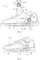
- FIG. 1 shows a lateral side view of an article of footwear 10.
- the article of footwear 10 includes a magnetic fastener 12 that is shown unfastened in FIG. 1 and fastened in FIG. 2 .
- the magnetic fastener 12 includes a male fastener portion 12A and a female fastener portion 12B each of which are secured to different portions of an upper 14 of the article of footwear. As shown in FIGS.
- the magnetic fastener 12 is configured for easy and quick magnetic fastening and unfastening of the male fastener portion 12A to the female fastener portion 12B to respectively tighten and loosen the upper 14 around afoot 19 disposed in afoot-receiving cavity 16 (foot 19 shown in phantom in FIGS. 7 and 8 ).
- the article of footwear 10 includes a sole structure 18 that underlies the upper 14.
- the sole structure 18 is shown as a single, one-piece, unitary midsole and outsole, but the sole structure 18 of the article of footwear 10 may have any configuration within the scope of the present teachings.
- the sole structure 18 may include one or more sole components that may be separate sole layers, such as an outsole and one or more midsole layers.
- the sole structure 18 may incorporate fluid-filled chambers, plates, moderators, or other elements that further attenuate forces, enhance stability, or influence the motions of the foot.
- the sole structure 18 as shown as a unitary midsole and outsole may be formed from a compressible polymer foam element (e.g., a polyurethane or ethylvinylacetate foam) that attenuates ground reaction forces (i.e., provides cushioning) when compressed between the foot and the ground during walking, running, or other ambulatory activities.
- Discrete outsole elements such as of a wear-resistant rubber material that may be textured to impart traction, and/or traction elements such as tread elements or cleats may be secured to a bottom surface of the sole structure 18.
- the upper 14 is secured to the sole structure 18.
- a lower extremity of the upper 14 may be bonded or otherwise secured to the sole structure 18 as shown in FIGS. 7 and 8 .
- a strobel (not shown) may be secured to the lower extremity of the upper 14 and to the sole structure 18, or the upper 14 may continue under the foot 19 in a sock configuration.
- An insole (not shown) may overlie the sole structure 18 within the foot-receiving cavity 16.
- the upper 14 is configured to receive and retain the foot 19 in the foot-receiving cavity 16 so that the foot 19 is supported on the sole structure 18 with the sole structure 18 positioned below the foot 19, and between the foot 19 and the ground.
- the article of footwear 10 has a forefoot portion 20, a midfoot portion 22 and a heel portion 24. Both the upper 14 and the sole structure 18 extend in and partially define the forefoot portion 20, the midfoot portion 22 and the heel portion 24 indicated in FIG. 2 .
- the article of footwear 10 has a lateral side 30 ( FIG. 1 ) and a medial side 32 (shown in FIGS. 7 and 8 ) opposite from the lateral side 30. The lateral side 30 and the medial side 32 extend through each of forefoot region 20, the midfoot region 22, and the heel region 24 and correspond with opposite sides of the article of footwear 10.
- the forefoot region 20, the midfoot region 22, the heel region 24, the lateral side 30 and the medial side 32 are not intended to demarcate precise areas of footwear 10, but are instead intended to represent general areas of the article footwear 10 to aid in the discussion.
- An article of footwear for a right foot has a mirror image of that shown, and is within the scope of the present teachings.
- the upper 14 may be a variety of materials, such as leather, textiles, polymers, cotton, foam, composites, etc.
- the upper 14 may be a polymeric material capable of providing elasticity to the upper 14 and may be of braided construction, a knitted (e.g., warp-knitted) construction or a woven construction.
- the upper 14 is a soft, flexible material and may include multiple layers.
- a first portion 34 of the upper 14 includes a strap 36.
- a second portion 38 of the upper 14 includes the lateral side 30 of the upper.
- the female fastener portion 12B is secured to the lateral side 30 of the upper 14 as shown in FIG. 1 .
- An inner side 40 of the strap 36 is contiguous with the lateral side 30 of the upper in a unitary construction. Stated differently, the material of the upper 14 that forms the lateral side 30 also forms the inner side of the strap 36, and extends without interruption from the lateral side 30 to the strap 36.
- the male fastener portion 12A is disposed on and secured to the inner side 40 of the strap 36.
- an outer side 42 of the strap 36 is contiguous with the medial side 32 of the upper 14 in a unitary construction in that the material of the upper 14 that forms the medial side 32 also forms the outer side 42 of the strap 36, and extends without interruption from the medial side 32 to the strap 36.
- the inner side 40 of the strap 36 may be sewn or otherwise secured to the outer side 42 of the strap 36 at a seam 44 where the sides 40, 42 meet, as shown in FIG. 7 , so that an inner surface 46 of the inner side 40 of the strap 36 confronts an inner surface 48 of the outer side 42 of the strap 36.
- the entire upper 14 including the lateral and medial sides 30, 32 and the strap 36 can be an integral one-piece unit, such as by knitting or otherwise.
- the strap 36 tapers in width (i.e., the width of the strap 36 is in a fore-aft direction of the article of footwear 10) from a proximal portion 49 of the strap 36 proximate the foot-receiving cavity 16 a distal portion 50 of the strap 36.
- the fore-aft direction of the article of footwear 10 is the longitudinal direction that extends from the heel portion 24 toward the forefoot portion 20 along a longitudinal midline L (shown in FIG. 1 and FIG. 7 ) of the article of footwear 10.
- the male fastener portion 12A is secured adjacent to the distal portion 50.
- the strap 36 is shown in a lifted position such as by a user's hand (not shown) midway through moving the strap 36 to fasten the male fastener portion 12A to the female fastener portion 12B.
- the strap 36 is of a sufficient length that it can be pulled over the instep of the foot 19 downward and rearward from its position in FIG. 1 to the secured position in FIG. 2 in which the male fastener portion 12A is magnetically fastened to the female fastener portion 12B.
- the inner side 40 of the strap 36 confronts an exterior surface 52 of the lateral side 30 of the upper 14 when the male fastener portion 12A is magnetically fastened to the female fastener portion 12B, as best shown in FIG. 8 .
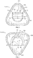
- FIG. 3 shows the male fastener portion 12A, including a first base 60A and a male connector portion 62A that protrudes from the first base 60A.
- the female fastener portion 12B also has a second base 60B and a female connector portion 62B that at least partially protrudes from and is surrounded laterally and from below by the second base 62. At least one of the connector portions 62A or 62B is magnetic.
- the bases 60A, 60B may be a flexible rubber or other polymeric material that can be stitched, adhered, or otherwise secured to the upper 14.
- the first base 60A is stitched to the upper 14 with stitching 64 through a thinned groove 66 of the first base 60.
- the groove 66 is shown in cross-sectional view.
- the groove 66 surrounds the male connector portion 62A and generally corresponds to the shape of an outer periphery of the first base 60A.
- the second base 60B also has a thinned groove 66 that surrounds the female connector portion 62B and generally corresponds to the shape of an outer periphery of the second base 60B.
- the second base 60B is stitched to the lateral side 30 of the upper 14 with stitching 64 through the thinned groove 66.
- the connector portion 62A of the male fastener portion 12A includes a straight side 68, a curved side 70, and corners 72 at which the straight side and the curved side meet.
- the straight side 68, the curved side 70, and one or more corners 72 at least partially define an outer periphery MP of the male connector portion 62A.
- the curved side 70 of the male connector portion 62A is U-shaped in plan view of FIG. 3 , and is also sloped. Stated differently, and as best shown in FIG. 5 , the curved side 70 of the male connector portion 62A extends at an obtuse angle A1 from the first base 60A such that the male connector portion 62A tapers in width in a direction away from the first base 60A at the curved side 70.
- a distal portion of the connector portion 62A (i.e., the portion furthest from the first base 60A) has a first width W1
- a proximal portion of the connector portion 62A i.e., the portion closest to the first base 60A
- the second base 60B of the female fastener portion 12B has a slight recess 74 in which the female connector portion 62B is secured such as with adhesive.
- the female connector portion 62B may have a flange that fits within a slot of the second base 60B at a perimeter of the recess 74.
- the female connector portion 62B of the female fastener portion 12B also defines a recess 76 which is a sub-portion of the recess 74.
- the outer periphery FP of the recess 76 is asymmetric about a center axis C of the recess 76.
- the center axis C extends in the direction of the depth of the recess 76, i.e., perpendicular to the second base 60B.
- the second base 60B defines a straight wall 78 bounding the recess 74 and also bounds the recess 76.
- the female connector portion 62B includes a curved wall 80 that bounds the recess 76.
- the curved wall 80 is U-shaped. The curved wall 80 and the straight wall 78 thus substantially define the outer perimeter FP of the recess 76 and cause the recess 76 to be asymmetrical about the center axis C.
- the curved wall 80 has a first height H1
- the straight wall 78 has a second height H2 that is less than the first height.
- the lower height H2 may ease entry of the male connector portion 62A into the recess 76 if the strap 36 is pulled sufficiently far so that the curved side 70 is to the right of the position shown in FIG. 5 , and then is moved to approach the curved wall 80 in a downward and leftward direction in the view of FIG. 5 .
- entry of the male connector portion 62A into the recess 76 can occur from slightly above the straight wall 78 and downward back toward the curved wall 80 instead of straight downward along the center axis C as would be required if the straight wall 78 was of the same height as the curved wall 80.
- the female fastener portion 12B is disposed on and secured to the lateral side 30 of the upper 14 with the curved wall 80 generally above the straight wall 78.
- This enables the curved wall 80 to act as a barrier against movement of the male fastener portion 12A, such as when forces on the strap 36 pull the male fastener portion 12A against the curved wall 80.
- the curved wall 80 helps retain the fastener 12 in the fastened position.
- the curved wall 80 is sloped outward such that it extends at an obtuse angle A2 relative to the second base 60B, causing the recess 76 to be wider at a distal portion 80A of the curved wall 80 than at a proximal portion 80B of the curved wall 80. Additionally, the angle A1 of the curved side 70 matches the angle A2 of the curved wall 80 such that the curved side 70 is flush with the curved wall 80 when the male connector portion 62A is in the recess 76.
- the sloped configuration of the curved wall 80 and the curved side 70 help to center the male connector portion 62A within the recess 76 of the female fastener portion 12B.
- the male connector portion 62A is stepped at the straight side 68 the such that the male connector portion 62A overlays the base 60B of the female fastener portion 12B with a terminal wall 69 outward of the recess 76 at the straight wall 78.
- the male connector portion 62A fits into the recess 76 when the male fastener portion 12A is in a first orientation relative to the female fastener portion 12B.
- the straight side 68 is parallel with the straight wall 78 and the curved side 70 is flush with the curved wall 80. Due to the asymmetric recess 76, the male connector portion 62A is generally confined to this first orientation when in the recess 76.
- the male fastener portion 12A is urged to rotate about the center axis C of the recess 76 away from the first orientation, one of the corners 72 will interfere with the female fastener portion 12B at the straight wall 78.
- the male fastener portion 12A is urged to twist slightly clockwise about the center axis C such as by tensile or other forces on the strap 36, the straight side 68 is no longer parallel to the straight wall 78, and the right corner 72 interferes with the straight wall 78 as represented in phantom by the straight side in position 68A.
- the female fastener portion 12B thereby limits twisting of the male connector portion 62A within the recess 76.
- the tapered shape of the strap 36 is beneficial as it flares wider proximate the foot-receiving cavity 16 so that it provides tension and support over a wide swatch of the instep.
- the wider proximal portion 49 causes forces to be applied over a wider range of directions on the male fastener portion 12A when in the fastened position, which could urge the male connector portion 62A to twist about the center axis C.
- the configuration of the asymmetrical recess 76 and the interfering straight wall 78 is particularly useful in combination with an upper 14 having a strap that is tapered such as tapered strap 36.
- the curved wall 80 may have a slot along its lower inner periphery adjacent the recess 76, at the proximal portion 80B.
- the distal portion of the curved side 70 of the male connector portion 62A may have a flange around its perimeter.
- the flange may be sized to slide into the slot when the male connector portion 62A is fit into the recess 76.
- the slot may have a height taller than the height H1 of the straight wall 78 and the ends of the slot may be open near the straight wall 78, so that the flange can be slid into the slot if the male connector portion 62A enters the recess 76 from just above the straight wall 78 and in a direction that is downward and toward the curved wall 70.
- the outer periphery 82A of the base 60A of the male fastener portion 12A and an outer periphery 82B of the base 60B of the female fastener portion 12B are of a substantially identical shape.
- each may be triangular with rounded corners as shown.
- other substantially identical shapes may be used within the scope of the present disclosure.
- the connector portions 62A, 62B are disposed on their respective bases 60A, 60B so that the male connector portion 62A is aligned with the recess 76 when the outer periphery 82A of the first base 60A of the male fastener portion 12A is aligned with the outer periphery 82B of the second base 60B of the female fastener portion 12B.
- the connector portion 62A is aligned with the recess 76.
- the female fastener portion 12B is secured to the upper 14 so that the peak 84A of the second base 60B of the female fastener portion 12B is disposed downward and rearward on the lateral side 30 of the upper 14. Aligning the male fastener portion 12A with the female fastener portion 12B to quickly secure the fastener 12 may be simplified in such an embodiment, as the corresponding peak 84A of the first base 60A of the male fastener portion 12A generally points in the direction that the strap 36 is pulled during fastening.
- the peaks 84A, 84B can be aligned and the male fastener portion 12A will be aligned with the female fastener portion 12B with little or no adjustments in the direction of pull.
- Simply pulling the strap 36 rearward and downward will position the male fastener portion 12A above the female fastener portion 12B.
- the magnetic force of the magnetic material of one or both connector portions 62A, 62B will tend to pull the male connector portion 62A into the recess 76 in the first orientation.
- An article of footwear comprising: an upper defining a foot-receiving cavity; a magnetic fastener including a male fastener portion fixed to a first portion of the upper and a female fastener portion fixed to a second portion of the upper, wherein the male fastener portion is configured to magnetically fasten to the female fastener portion to tighten the upper around the foot-receiving cavity; wherein the female fastener portion defines a recess with an outer periphery that is asymmetric about a center axis of the recess; and wherein the male fastener portion fits into the recess when the male fastener portion is in a first orientation relative to the female fastener portion, and interferes with the female fastener portion when the male fastener portion is urged to rotate about the center axis of the recess away from the first orientation.
- Clause 2 The article of footwear of Clause 1, wherein: the male fastener portion includes a straight side, a curved side, and a corner at which the straight side and the curved side meet; the female fastener portion includes a straight wall and a curved wall; the male fastener portion fits into the recess in the first orientation with the curved side adjacent to the curved wall, and the straight side adjacent to the straight wall; and wherein the corner interferes with the straight wall when the male fastener portion is urged to rotate about the center axis of the recess.
- Clause 3 The article of footwear of Clause 2, wherein the curved side is U-shaped, and the curved wall is U-shaped.
- Clause 4 The article of footwear of any of Clauses 2-3, wherein the curved wall has a first height, and the straight wall has a second height less than the first height.
- Clause 5 The article of footwear of Clause 4, wherein the female fastener portion is disposed on the lateral side of the upper with the curved wall generally above the straight wall.
- Clause 6 The article of footwear of any of Clauses 4-5, wherein the male fastener portion is stepped at the straight side such that the male fastener portion overlays the female fastener portion outward of the recess at the straight wall of the female fastener portion.
- Clause 7 The article of footwear of any of Clauses 2-6, wherein the curved wall is sloped such that the recess is wider at a distal portion of the curved wall than at a proximal portion of the curved wall; and wherein the curved side of the male fastener portion is sloped such that the curved side is flush with the curved wall when the male fastener portion is in the recess.
- Clause 8 The article of footwear of any of Clauses 2-7, wherein: the male fastener portion includes a first base and a male connector portion that protrudes from the base, the male connector portion having the straight side, the curved side, and the comer; the female fastener portion includes a second base and a female connector portion surrounded by the second base, the female connector portion having the curved wall and the recess, and the second base defining the straight wall; and an outer periphery of the first base and an outer periphery of the second base are of a substantially identical shape.
- Clause 9 The article of footwear of Clause 8, wherein the male connector portion is aligned with the recess when the outer periphery of the first base of the male fastener portion is aligned with the outer periphery of the second base of the female fastener portion.
- Clause 10 The article of footwear of any of Clauses 8-9, wherein the substantially identical shape is generally triangular, with a peak of the second base of the female fastener portion disposed downward and rearward on the lateral side of the upper.
- Clause 11 The article of footwear of any of Clauses 1-10, wherein: the first portion of the upper includes a strap, and the second portion of the upper defines a lateral side of the upper; an inner side of the strap is contiguous with the lateral side of the upper in a unitary construction; the male fastener portion is secured to the inner side of the strap; the upper includes a medial side; and an outer side of the strap is contiguous with the medial side of the upper in a unitary construction.
- Clause 12 The article of footwear of Clause 11, wherein the inner side of the strap confronts an exterior surface of the lateral side of the upper when the male fastener portion is magnetically fastened to the female fastener portion.
- Clause 13 The article of footwear of any of Clauses 11-12, wherein the strap tapers in width from a proximate portion of the strap to a distal portion of the strap.
- a magnetic fastener comprising: a male fastener portion and a female fastener portion, wherein the male fastener portion is configured to magnetically fasten to the female fastener portion; wherein the female fastener portion defines a recess with an outer periphery that is asymmetric about a center axis of the recess; and wherein the male fastener portion fits into the recess in the first orientation when the male fastener portion is in a first orientation relative to the female fastener portion, and interferes with the female fastener portion when the male fastener portion is urged to rotate about the center axis of the recess away from the first orientation, the female fastener portion thereby preventing twisting of the male fastener portion within the recess.
- Clause 15 The magnetic fastener of Clause 14, wherein: the male fastener portion includes a straight side, a curved side, and a corner at which the straight side and the curved side meet; the female fastener portion includes a straight wall and a curved wall; the male fastener portion fits into the recess with the curved side adjacent to the curved wall, and the straight side adjacent to the straight wall; and wherein the corner interferes with the straight wall when the male fastener portion is urged to rotate about the center axis of the recess.
- Clause 16 The magnetic fastener of Clause 15, wherein the curved side is U-shaped, and the curved wall is U-shaped.
- Clause 17 The magnetic fastener of any of Clauses 15-16, wherein the curved wall has a first height, and the straight wall has a second height less than the first height.
- Clause 18 The magnetic fastener of any of Clauses 15-17, wherein the straight side is stepped such that the male fastener portion overlays the female fastener portion outward of the recess at the straight wall.
- Clause 19 The magnetic fastener of any of Clauses 15-18, wherein: the male fastener portion includes a first base and a male connector portion that protrudes from the base, the male connector portion having the straight side, the curved side, and the comer; the female fastener portion includes a second base and a female connector portion surrounded by the second base, the female connector portion having the curved wall and the recess, and the second base defining the straight wall; and an outer periphery of the first base and an outer periphery of the second base are of a substantially identical shape.
- Clause 20 The magnetic fastener of Clause 19, wherein the connector portion is aligned with the recess when the outer periphery of the first base of the male fastener portion is aligned with the outer periphery of the second base of the female fastener portion.
- An "article of footwear”, a “footwear article of manufacture”, and “footwear” may be considered to be both a machine and a manufacture. Assembled, ready to wear footwear articles (e.g., shoes, sandals, boots, etc.), as well as discrete components of footwear articles (such as a midsole, an outsole, an upper component, etc.) prior to final assembly into ready to wear footwear articles, are considered and alternatively referred to herein in either the singular or plural as "article(s) of footwear”.
- footwear articles e.g., shoes, sandals, boots, etc.
- discrete components of footwear articles such as a midsole, an outsole, an upper component, etc.
- longitudinal refers to a direction extending a length of a component.
- a longitudinal direction of a shoe extends between a forefoot region and a heel region of the shoe.
- the term “forward” is used to refer to the general direction from a heel region toward a forefoot region
- the term “rearward” is used to refer to the opposite direction, i.e., the direction from the forefoot region toward the heel region.
- a component may be identified with a longitudinal axis as well as a forward and rearward longitudinal direction along that axis.
- vertical refers to a direction generally perpendicular to both the lateral and longitudinal directions. For example, in cases where a sole is planted flat on a ground surface, the vertical direction may extend from the ground surface upward. It will be understood that each of these directional adjectives may be applied to individual components of a sole.
- upward or “upwards” refers to the vertical direction pointing towards a top of the component, which may include an instep, a fastening region and/or a throat of an upper.
- downward or “downwards” refers to the vertical direction pointing opposite the upwards direction, and may generally point towards the sole, or towards the outermost components of the sole.
- proximal refers to a direction that is nearer a center of a footwear component, or is closer toward a foot when the foot is inserted in the article as it is worn by a user.
- distal refers to a relative position that is further away from a center of the footwear component or is further from a foot when the foot is inserted in the article as it is worn by a user.
- proximal and distal may be understood to provide generally opposing terms to describe the relative spatial position of a footwear component.
Landscapes
- Engineering & Computer Science (AREA)
- Textile Engineering (AREA)
- Footwear And Its Accessory, Manufacturing Method And Apparatuses (AREA)
Abstract
Description
- This application claims the benefit of priority to
United States Provisional Application No. 62/552,115, filed August 30, 2017 - The present teachings generally include a magnetic fastener and an article of footwear with a magnetic fastener.
- An upper of an article of footwear is generally secured around a foot using laces, straps, or other fastening mechanisms. The construction of the upper, the complexity of the fastening mechanism, and the level of tightness may be dependent upon the activity to be undertaken.
- The drawings described herein are for illustrative purposes only, are schematic in nature, and are intended to be exemplary rather than to limit the scope of the disclosure.
-
FIG. 1 is a schematic illustration in lateral side view of an article of footwear with a magnetic fastener unfastened. -
FIG. 2 is a schematic illustration in lateral side view of the article of footwear ofFIG. 1 with the magnetic fastener fastened. -
FIG. 3 is a schematic illustration in plan view of a male fastener portion of the magnetic fastener ofFIGS. 1 and 2 . -
FIG. 4 is a schematic illustration in plan view of a female fastener portion of the magnetic fastener ofFIGS. 1 and 2 . -
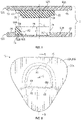
FIG. 5 is a schematic illustration in exploded cross-sectional view of the magnetic fastener ofFIGS. 1-2 taken at lines 5-5 inFIG. 6 . -
FIG. 6 is a schematic illustration in plan view of the magnetic fastener ofFIGS. 1-2 with the male fastener portion shown in hidden lines in a first orientation fit in a recess of the female fastener portion, and showing a second orientation of the male fastener portion in phantom. -
FIG. 7 is a schematic illustration in partial cross-sectional view of the article of footwear ofFIG. 1 taken at lines 7-7 inFIG. 1 . -
FIG. 8 is a schematic illustration in partial cross-sectional view of the article of footwear ofFIG. 2 taken at lines 8-8 inFIG. 2 . - In accordance with the present disclosure, a magnetic fastener is configured with interfitting male and female fastener portions that enable quick, one-handed fastening and unfastening. The male fastener portion is configured to fit in an asymmetric recess of the female fastener portion which largely confines the male fastener portion to a first orientation, preventing it from twisting relative to the female fastener portion. Strategically positioned walls of the female fastener provide a physical barrier that supplements the magnetic force in maintaining the secured position of the fastener. When used to secure an upper of an article of footwear around a foot, the upper may include a strap contiguous with the sides of the upper, and the fastener may secure a distal end of the strap to one of the sides to tighten the upper around the foot, with one-handed securement and release.
- More specifically, an article of footwear comprises an upper defining a foot-receiving cavity, and a magnetic fastener including a male fastener portion fixed to a first portion of the upper and a female fastener portion fixed to a second portion of the upper. The male fastener portion is configured to magnetically fasten to the female fastener portion to tighten the upper around the foot-receiving cavity. The female fastener portion defines a recess with an outer periphery that is asymmetric about a center axis of the recess. The male fastener portion fits into the recess when the male fastener portion is in a first orientation relative to the female fastener portion, and interferes with the female fastener portion when the male fastener portion is urged to rotate about the center axis of the recess away from the first orientation. The female fastener portion thereby limits twisting of the male fastener portion within the recess.
- In one or more embodiments, the male fastener portion includes a straight side, a curved side, and a corner at which the straight side and the curved side meet. The female fastener portion includes a straight wall and a curved wall. The male fastener portion fits into the recess in the first orientation with the curved side adjacent to the curved wall, and the straight side adjacent to the straight wall. The corner interferes with the straight wall when the male fastener portion is urged to rotate about the center axis of the recess.
- In one or more embodiments of the article of footwear, the curved side of the male fastener is U-shaped, and the curved wall of the female fastener is U-shaped. In these or other embodiments, the curved wall has a first height, and the straight wall has a second height less than the first height.
- In one or more embodiments of the article of footwear, the female fastener portion is disposed on the lateral side of the upper with the curved wall generally above the straight wall. This enables the curved wall to act as a barrier against movement of the male fastener portion, such as when forces on the magnetic fastener push the male fastener portion against the curved wall.
- In one or more embodiments of the article of footwear, the male fastener portion is stepped at the straight side such that the male fastener portion overlays the female fastener portion outward of the recess at the straight wall of the female fastener portion.
- In one or more embodiments of the article of footwear, the curved wall is sloped outward such that the recess is wider at a distal portion of the curved wall than at a proximal portion of the curved wall The curved side of the male fastener portion is also sloped such that the curved side is flush with the curved wall when the male fastener portion is in the recess. The sloped configuration of the curved wall and the curved side help to center the male portion within the recess of the female portion.
- In one or more embodiments of the article of footwear, the male fastener portion includes a first base and a male connector portion that protrudes from the base, the male connector portion having the straight side, the curved side, and the corner. The female fastener portion includes a second base and a female connector portion surrounded by the second base, the female connector portion having the curved wall and the recess, and the second base defining the straight wall. An outer periphery of the first base and an outer periphery of the second base are of a substantially identical shape. For example, each may be triangular with rounded corners. In such embodiments, the male connector portion is aligned with the recess when the outer periphery of the first base of the male fastener portion is aligned with the outer periphery of the second base of the female fastener portion.
- In one or more embodiments of the article of footwear, the substantially identical shape of the male fastener portion and the female fastener portion is generally triangular, with a peak of the second base of the female fastener portion disposed downward and rearward on the lateral side of the upper. Aligning the male fastener portion with the female fastener portion may be simplified in such an embodiment, as a corresponding peak of the first base of the male fastener portion generally points in the direction that the portion of the upper on which the male fastener portion is disposed is pulled during fastening.
- In one or more embodiments of the article of footwear, the first portion of the upper includes a strap, and the second portion of the upper defines a lateral side of the upper. An inner side of the strap is contiguous with the lateral side of the upper in a unitary construction. The male fastener portion is secured to the inner side of the strap. The upper includes a medial side, and an outer side of the strap is contiguous with the medial side of the upper in a unitary construction. The inner side of the strap confronts an exterior surface of the lateral side of the upper when the male fastener portion is magnetically fastened to the female fastener portion.
- In one or more embodiments of the article of footwear, the strap tapers in width from a proximate portion of the strap to a distal portion of the strap.
- Within the scope of the present disclosure, a magnetic fastener comprises a male fastener portion and a female fastener portion. The male fastener portion is configured to magnetically fasten to the female fastener portion. The female fastener portion defines a recess with an outer periphery that is asymmetric about a center axis of the recess. The male fastener portion fits into the recess when the male fastener portion is in a first orientation relative to the female fastener portion, and interferes with the female fastener portion when the male fastener portion is urged to rotate about the center axis of the recess away from the first orientation, the female fastener portion thereby preventing twisting of the male fastener portion within the recess.
- In one or more embodiments of the fastener, the male fastener portion includes a straight side, a curved side, and a corner at which the straight side and the curved side meet. The female fastener portion includes a straight wall and a curved wall. The male fastener portion fits into the recess with the curved side adjacent to the curved wall, and the straight side adjacent to the straight wall. The corner interferes with the straight wall when the male fastener portion is urged to rotate about the center axis of the recess.
- In one or more embodiments of the fastener, the curved side of the male fastener is U-shaped, and the curved wall of the female fastener is U-shaped. In these or other embodiments, the curved wall has a first height, and the straight wall has a second height less than the first height.
- In one or more embodiments of the fastener, the straight side of the male fastener portion is stepped such that the male fastener portion overlays the female fastener portion outward of the recess at the straight wall of the female fastener portion.
- In one or more embodiments of the fastener, the male fastener portion includes a first base and a male connector portion that protrudes from the base, the male connector portion having the straight side, the curved side, and the corner. The female fastener portion includes a second base and a female connector portion surrounded by the second base, the female connector portion having the curved wall and the recess, and the second base defining the straight wall. An outer periphery of the first base and an outer periphery of the second base are of a substantially identical shape. In such embodiments, the male connector portion is aligned with the recess when the outer periphery of the first base of the male fastener portion is aligned with the outer periphery of the second base of the female fastener portion.
- The above features and advantages and other features and advantages of the present teachings are readily apparent from the following detailed description of the modes for carrying out the present teachings when taken in connection with the accompanying drawings.
- Referring to the drawings, wherein like reference numbers refer to like components throughout the views,
FIG. 1 shows a lateral side view of an article offootwear 10. As further described herein, the article offootwear 10 includes amagnetic fastener 12 that is shown unfastened inFIG. 1 and fastened inFIG. 2 . More specifically, themagnetic fastener 12 includes amale fastener portion 12A and afemale fastener portion 12B each of which are secured to different portions of an upper 14 of the article of footwear. As shown inFIGS. 7 and 8 , themagnetic fastener 12 is configured for easy and quick magnetic fastening and unfastening of themale fastener portion 12A to thefemale fastener portion 12B to respectively tighten and loosen the upper 14 around afoot 19 disposed in afoot-receiving cavity 16 (foot 19 shown in phantom inFIGS. 7 and 8 ). - Referring to
FIG. 1 , the article offootwear 10 includes asole structure 18 that underlies the upper 14. Thesole structure 18 is shown as a single, one-piece, unitary midsole and outsole, but thesole structure 18 of the article offootwear 10 may have any configuration within the scope of the present teachings. For example, thesole structure 18 may include one or more sole components that may be separate sole layers, such as an outsole and one or more midsole layers. In further configurations, thesole structure 18 may incorporate fluid-filled chambers, plates, moderators, or other elements that further attenuate forces, enhance stability, or influence the motions of the foot. In one non-limiting example, thesole structure 18 as shown as a unitary midsole and outsole may be formed from a compressible polymer foam element (e.g., a polyurethane or ethylvinylacetate foam) that attenuates ground reaction forces (i.e., provides cushioning) when compressed between the foot and the ground during walking, running, or other ambulatory activities. Discrete outsole elements such as of a wear-resistant rubber material that may be textured to impart traction, and/or traction elements such as tread elements or cleats may be secured to a bottom surface of thesole structure 18. - The upper 14 is secured to the
sole structure 18. For example, a lower extremity of the upper 14 may be bonded or otherwise secured to thesole structure 18 as shown inFIGS. 7 and 8 . In other embodiments, a strobel (not shown) may be secured to the lower extremity of the upper 14 and to thesole structure 18, or the upper 14 may continue under thefoot 19 in a sock configuration. An insole (not shown) may overlie thesole structure 18 within the foot-receivingcavity 16. The upper 14 is configured to receive and retain thefoot 19 in the foot-receivingcavity 16 so that thefoot 19 is supported on thesole structure 18 with thesole structure 18 positioned below thefoot 19, and between thefoot 19 and the ground. - The article of
footwear 10 has aforefoot portion 20, amidfoot portion 22 and aheel portion 24. Both the upper 14 and thesole structure 18 extend in and partially define theforefoot portion 20, themidfoot portion 22 and theheel portion 24 indicated inFIG. 2 . The article offootwear 10 has a lateral side 30 (FIG. 1 ) and a medial side 32 (shown inFIGS. 7 and 8 ) opposite from thelateral side 30. Thelateral side 30 and themedial side 32 extend through each offorefoot region 20, themidfoot region 22, and theheel region 24 and correspond with opposite sides of the article offootwear 10. Theforefoot region 20, themidfoot region 22, theheel region 24, thelateral side 30 and themedial side 32 are not intended to demarcate precise areas offootwear 10, but are instead intended to represent general areas of thearticle footwear 10 to aid in the discussion. The article offootwear 10 shown in configured for a left foot. An article of footwear for a right foot has a mirror image of that shown, and is within the scope of the present teachings. - The upper 14 may be a variety of materials, such as leather, textiles, polymers, cotton, foam, composites, etc. In non-limiting examples, the upper 14 may be a polymeric material capable of providing elasticity to the upper 14 and may be of braided construction, a knitted (e.g., warp-knitted) construction or a woven construction. As shown, the upper 14 is a soft, flexible material and may include multiple layers.
- Referring to
FIG. 7 , afirst portion 34 of the upper 14 includes astrap 36. A second portion 38 of the upper 14 includes thelateral side 30 of the upper. Thefemale fastener portion 12B is secured to thelateral side 30 of the upper 14 as shown inFIG. 1 . Aninner side 40 of thestrap 36 is contiguous with thelateral side 30 of the upper in a unitary construction. Stated differently, the material of the upper 14 that forms thelateral side 30 also forms the inner side of thestrap 36, and extends without interruption from thelateral side 30 to thestrap 36. Themale fastener portion 12A is disposed on and secured to theinner side 40 of thestrap 36. - Similarly, an
outer side 42 of thestrap 36 is contiguous with themedial side 32 of the upper 14 in a unitary construction in that the material of the upper 14 that forms themedial side 32 also forms theouter side 42 of thestrap 36, and extends without interruption from themedial side 32 to thestrap 36. Theinner side 40 of thestrap 36 may be sewn or otherwise secured to theouter side 42 of thestrap 36 at a seam 44 where thesides FIG. 7 , so that aninner surface 46 of theinner side 40 of thestrap 36 confronts aninner surface 48 of theouter side 42 of thestrap 36. Alternatively, the entire upper 14 including the lateral andmedial sides strap 36 can be an integral one-piece unit, such as by knitting or otherwise. - As best shown in
FIG. 1 , thestrap 36 tapers in width (i.e., the width of thestrap 36 is in a fore-aft direction of the article of footwear 10) from aproximal portion 49 of thestrap 36 proximate the foot-receiving cavity 16 adistal portion 50 of thestrap 36. The fore-aft direction of the article offootwear 10 is the longitudinal direction that extends from theheel portion 24 toward theforefoot portion 20 along a longitudinal midline L (shown inFIG. 1 andFIG. 7 ) of the article offootwear 10. Themale fastener portion 12A is secured adjacent to thedistal portion 50. - In
FIGS. 1 and7 , thestrap 36 is shown in a lifted position such as by a user's hand (not shown) midway through moving thestrap 36 to fasten themale fastener portion 12A to thefemale fastener portion 12B. Thestrap 36 is of a sufficient length that it can be pulled over the instep of thefoot 19 downward and rearward from its position inFIG. 1 to the secured position inFIG. 2 in which themale fastener portion 12A is magnetically fastened to thefemale fastener portion 12B. Theinner side 40 of thestrap 36 confronts anexterior surface 52 of thelateral side 30 of the upper 14 when themale fastener portion 12A is magnetically fastened to thefemale fastener portion 12B, as best shown inFIG. 8 . - Referring to
FIGS. 3-6 , features of thefastener 12 are shown in further detail.FIG. 3 shows themale fastener portion 12A, including afirst base 60A and amale connector portion 62A that protrudes from thefirst base 60A. Thefemale fastener portion 12B also has asecond base 60B and afemale connector portion 62B that at least partially protrudes from and is surrounded laterally and from below by the second base 62. At least one of theconnector portions connector portions fastener portions bases - As shown in
FIG. 1 , thefirst base 60A is stitched to the upper 14 withstitching 64 through a thinnedgroove 66 of the first base 60. InFIG. 5 , thegroove 66 is shown in cross-sectional view. Thegroove 66 surrounds themale connector portion 62A and generally corresponds to the shape of an outer periphery of thefirst base 60A. Thesecond base 60B also has a thinnedgroove 66 that surrounds thefemale connector portion 62B and generally corresponds to the shape of an outer periphery of thesecond base 60B. Thesecond base 60B is stitched to thelateral side 30 of the upper 14 withstitching 64 through the thinnedgroove 66. - The
connector portion 62A of themale fastener portion 12A includes astraight side 68, acurved side 70, andcorners 72 at which the straight side and the curved side meet. Thestraight side 68, thecurved side 70, and one ormore corners 72 at least partially define an outer periphery MP of themale connector portion 62A. Thecurved side 70 of themale connector portion 62A is U-shaped in plan view ofFIG. 3 , and is also sloped. Stated differently, and as best shown inFIG. 5 , thecurved side 70 of themale connector portion 62A extends at an obtuse angle A1 from thefirst base 60A such that themale connector portion 62A tapers in width in a direction away from thefirst base 60A at thecurved side 70. For example, as shown inFIG. 3 , a distal portion of theconnector portion 62A (i.e., the portion furthest from thefirst base 60A) has a first width W1, while a proximal portion of theconnector portion 62A (i.e., the portion closest to thefirst base 60A) has a second width W2 greater than the first width W1). - With reference to
FIG. 5 , thesecond base 60B of thefemale fastener portion 12B has aslight recess 74 in which thefemale connector portion 62B is secured such as with adhesive. Alternatively or additionally, thefemale connector portion 62B may have a flange that fits within a slot of thesecond base 60B at a perimeter of therecess 74. Thefemale connector portion 62B of thefemale fastener portion 12B also defines arecess 76 which is a sub-portion of therecess 74. As best shown inFIG. 4 , the outer periphery FP of therecess 76 is asymmetric about a center axis C of therecess 76. The center axis C extends in the direction of the depth of therecess 76, i.e., perpendicular to thesecond base 60B. Thesecond base 60B defines astraight wall 78 bounding therecess 74 and also bounds therecess 76. Thefemale connector portion 62B includes acurved wall 80 that bounds therecess 76. Thecurved wall 80 is U-shaped. Thecurved wall 80 and thestraight wall 78 thus substantially define the outer perimeter FP of therecess 76 and cause therecess 76 to be asymmetrical about the center axis C. - As best shown in
FIG. 5 , thecurved wall 80 has a first height H1, and thestraight wall 78 has a second height H2 that is less than the first height. The lower height H2 may ease entry of themale connector portion 62A into therecess 76 if thestrap 36 is pulled sufficiently far so that thecurved side 70 is to the right of the position shown inFIG. 5 , and then is moved to approach thecurved wall 80 in a downward and leftward direction in the view ofFIG. 5 . In other words, entry of themale connector portion 62A into therecess 76 can occur from slightly above thestraight wall 78 and downward back toward thecurved wall 80 instead of straight downward along the center axis C as would be required if thestraight wall 78 was of the same height as thecurved wall 80. - As shown in
FIG. 1 , thefemale fastener portion 12B is disposed on and secured to thelateral side 30 of the upper 14 with thecurved wall 80 generally above thestraight wall 78. This enables thecurved wall 80 to act as a barrier against movement of themale fastener portion 12A, such as when forces on thestrap 36 pull themale fastener portion 12A against thecurved wall 80. For example, if thestrap 36 is under tension in the secured position ofFIG. 2 in which thefastener 12 is fastened, in addition to the magnetic force holding thefastener 12 fastened, thecurved wall 80 helps retain thefastener 12 in the fastened position. - The
curved wall 80 is sloped outward such that it extends at an obtuse angle A2 relative to thesecond base 60B, causing therecess 76 to be wider at adistal portion 80A of thecurved wall 80 than at aproximal portion 80B of thecurved wall 80. Additionally, the angle A1 of thecurved side 70 matches the angle A2 of thecurved wall 80 such that thecurved side 70 is flush with thecurved wall 80 when themale connector portion 62A is in therecess 76. The sloped configuration of thecurved wall 80 and thecurved side 70 help to center themale connector portion 62A within therecess 76 of thefemale fastener portion 12B. Themale connector portion 62A is stepped at thestraight side 68 the such that themale connector portion 62A overlays the base 60B of thefemale fastener portion 12B with aterminal wall 69 outward of therecess 76 at thestraight wall 78. - The
male connector portion 62A fits into therecess 76 when themale fastener portion 12A is in a first orientation relative to thefemale fastener portion 12B. Namely, in the first orientation, thestraight side 68 is parallel with thestraight wall 78 and thecurved side 70 is flush with thecurved wall 80. Due to theasymmetric recess 76, themale connector portion 62A is generally confined to this first orientation when in therecess 76. For example, when themale fastener portion 12A is urged to rotate about the center axis C of therecess 76 away from the first orientation, one of thecorners 72 will interfere with thefemale fastener portion 12B at thestraight wall 78. For example, inFIG. 6 , if themale fastener portion 12A is urged to twist slightly clockwise about the center axis C such as by tensile or other forces on thestrap 36, thestraight side 68 is no longer parallel to thestraight wall 78, and theright corner 72 interferes with thestraight wall 78 as represented in phantom by the straight side inposition 68A. Thefemale fastener portion 12B thereby limits twisting of themale connector portion 62A within therecess 76. The tapered shape of thestrap 36 is beneficial as it flares wider proximate the foot-receivingcavity 16 so that it provides tension and support over a wide swatch of the instep. However, the widerproximal portion 49 causes forces to be applied over a wider range of directions on themale fastener portion 12A when in the fastened position, which could urge themale connector portion 62A to twist about the center axis C. Accordingly, the configuration of theasymmetrical recess 76 and the interferingstraight wall 78 is particularly useful in combination with an upper 14 having a strap that is tapered such as taperedstrap 36. - In an embodiment, the
curved wall 80 may have a slot along its lower inner periphery adjacent therecess 76, at theproximal portion 80B. The distal portion of thecurved side 70 of themale connector portion 62A may have a flange around its perimeter. The flange may be sized to slide into the slot when themale connector portion 62A is fit into therecess 76. The slot may have a height taller than the height H1 of thestraight wall 78 and the ends of the slot may be open near thestraight wall 78, so that the flange can be slid into the slot if themale connector portion 62A enters therecess 76 from just above thestraight wall 78 and in a direction that is downward and toward thecurved wall 70. - As is evident in
FIGS. 3-4 and6 , theouter periphery 82A of thebase 60A of themale fastener portion 12A and anouter periphery 82B of the base 60B of thefemale fastener portion 12B are of a substantially identical shape. For example, each may be triangular with rounded corners as shown. However, other substantially identical shapes may be used within the scope of the present disclosure. - Additionally, the
connector portions respective bases male connector portion 62A is aligned with therecess 76 when theouter periphery 82A of thefirst base 60A of themale fastener portion 12A is aligned with theouter periphery 82B of thesecond base 60B of thefemale fastener portion 12B. For example, when peak 84A of thefirst base 60A is aligned withpeak 84B of thesecond base 60B (with themale fastener portion 12A inverted from the position ofFIG. 3 ), theconnector portion 62A is aligned with therecess 76. - As shown in
FIG. 1 , thefemale fastener portion 12B is secured to the upper 14 so that thepeak 84A of thesecond base 60B of thefemale fastener portion 12B is disposed downward and rearward on thelateral side 30 of the upper 14. Aligning themale fastener portion 12A with thefemale fastener portion 12B to quickly secure thefastener 12 may be simplified in such an embodiment, as thecorresponding peak 84A of thefirst base 60A of themale fastener portion 12A generally points in the direction that thestrap 36 is pulled during fastening. In other words, during the pulling motion used to tighten thestrap 36, thepeaks male fastener portion 12A will be aligned with thefemale fastener portion 12B with little or no adjustments in the direction of pull. Simply pulling thestrap 36 rearward and downward will position themale fastener portion 12A above thefemale fastener portion 12B. Once in the vicinity of thefemale portion 12B, the magnetic force of the magnetic material of one or bothconnector portions male connector portion 62A into therecess 76 in the first orientation. - The following Clauses provide example configurations of an article of footwear disclosed herein.
- Clause 1: An article of footwear comprising: an upper defining a foot-receiving cavity; a magnetic fastener including a male fastener portion fixed to a first portion of the upper and a female fastener portion fixed to a second portion of the upper, wherein the male fastener portion is configured to magnetically fasten to the female fastener portion to tighten the upper around the foot-receiving cavity; wherein the female fastener portion defines a recess with an outer periphery that is asymmetric about a center axis of the recess; and wherein the male fastener portion fits into the recess when the male fastener portion is in a first orientation relative to the female fastener portion, and interferes with the female fastener portion when the male fastener portion is urged to rotate about the center axis of the recess away from the first orientation.
- Clause 2: The article of footwear of Clause 1, wherein: the male fastener portion includes a straight side, a curved side, and a corner at which the straight side and the curved side meet; the female fastener portion includes a straight wall and a curved wall; the male fastener portion fits into the recess in the first orientation with the curved side adjacent to the curved wall, and the straight side adjacent to the straight wall; and wherein the corner interferes with the straight wall when the male fastener portion is urged to rotate about the center axis of the recess.
- Clause 3: The article of footwear of Clause 2, wherein the curved side is U-shaped, and the curved wall is U-shaped.
- Clause 4: The article of footwear of any of Clauses 2-3, wherein the curved wall has a first height, and the straight wall has a second height less than the first height.
- Clause 5: The article of footwear of Clause 4, wherein the female fastener portion is disposed on the lateral side of the upper with the curved wall generally above the straight wall.
- Clause 6: The article of footwear of any of Clauses 4-5, wherein the male fastener portion is stepped at the straight side such that the male fastener portion overlays the female fastener portion outward of the recess at the straight wall of the female fastener portion.
- Clause 7: The article of footwear of any of Clauses 2-6, wherein the curved wall is sloped such that the recess is wider at a distal portion of the curved wall than at a proximal portion of the curved wall; and wherein the curved side of the male fastener portion is sloped such that the curved side is flush with the curved wall when the male fastener portion is in the recess.
- Clause 8: The article of footwear of any of Clauses 2-7, wherein: the male fastener portion includes a first base and a male connector portion that protrudes from the base, the male connector portion having the straight side, the curved side, and the comer; the female fastener portion includes a second base and a female connector portion surrounded by the second base, the female connector portion having the curved wall and the recess, and the second base defining the straight wall; and an outer periphery of the first base and an outer periphery of the second base are of a substantially identical shape.
- Clause 9: The article of footwear of
Clause 8, wherein the male connector portion is aligned with the recess when the outer periphery of the first base of the male fastener portion is aligned with the outer periphery of the second base of the female fastener portion. - Clause 10: The article of footwear of any of Clauses 8-9, wherein the substantially identical shape is generally triangular, with a peak of the second base of the female fastener portion disposed downward and rearward on the lateral side of the upper.
- Clause 11: The article of footwear of any of Clauses 1-10, wherein: the first portion of the upper includes a strap, and the second portion of the upper defines a lateral side of the upper; an inner side of the strap is contiguous with the lateral side of the upper in a unitary construction; the male fastener portion is secured to the inner side of the strap; the upper includes a medial side; and an outer side of the strap is contiguous with the medial side of the upper in a unitary construction.
- Clause 12: The article of footwear of Clause 11, wherein the inner side of the strap confronts an exterior surface of the lateral side of the upper when the male fastener portion is magnetically fastened to the female fastener portion.
- Clause 13: The article of footwear of any of Clauses 11-12, wherein the strap tapers in width from a proximate portion of the strap to a distal portion of the strap.
- Clause 14: A magnetic fastener comprising: a male fastener portion and a female fastener portion, wherein the male fastener portion is configured to magnetically fasten to the female fastener portion; wherein the female fastener portion defines a recess with an outer periphery that is asymmetric about a center axis of the recess; and wherein the male fastener portion fits into the recess in the first orientation when the male fastener portion is in a first orientation relative to the female fastener portion, and interferes with the female fastener portion when the male fastener portion is urged to rotate about the center axis of the recess away from the first orientation, the female fastener portion thereby preventing twisting of the male fastener portion within the recess.
- Clause 15: The magnetic fastener of
Clause 14, wherein: the male fastener portion includes a straight side, a curved side, and a corner at which the straight side and the curved side meet; the female fastener portion includes a straight wall and a curved wall; the male fastener portion fits into the recess with the curved side adjacent to the curved wall, and the straight side adjacent to the straight wall; and wherein the corner interferes with the straight wall when the male fastener portion is urged to rotate about the center axis of the recess. - Clause 16: The magnetic fastener of Clause 15, wherein the curved side is U-shaped, and the curved wall is U-shaped.
- Clause 17: The magnetic fastener of any of Clauses 15-16, wherein the curved wall has a first height, and the straight wall has a second height less than the first height.
- Clause 18: The magnetic fastener of any of Clauses 15-17, wherein the straight side is stepped such that the male fastener portion overlays the female fastener portion outward of the recess at the straight wall.
- Clause 19: The magnetic fastener of any of Clauses 15-18, wherein: the male fastener portion includes a first base and a male connector portion that protrudes from the base, the male connector portion having the straight side, the curved side, and the comer; the female fastener portion includes a second base and a female connector portion surrounded by the second base, the female connector portion having the curved wall and the recess, and the second base defining the straight wall; and an outer periphery of the first base and an outer periphery of the second base are of a substantially identical shape.
- Clause 20: The magnetic fastener of
Clause 19, wherein the connector portion is aligned with the recess when the outer periphery of the first base of the male fastener portion is aligned with the outer periphery of the second base of the female fastener portion. - To assist and clarify the subsequent description of various embodiments, various terms are defined herein. Unless otherwise indicated, the following definitions apply throughout this specification (including the claims).
- An "article of footwear", a "footwear article of manufacture", and "footwear" may be considered to be both a machine and a manufacture. Assembled, ready to wear footwear articles (e.g., shoes, sandals, boots, etc.), as well as discrete components of footwear articles (such as a midsole, an outsole, an upper component, etc.) prior to final assembly into ready to wear footwear articles, are considered and alternatively referred to herein in either the singular or plural as "article(s) of footwear".
- "A", "an", "the", "at least one", and "one or more" are used interchangeably to indicate that at least one of the items is present. A plurality of such items may be present unless the context clearly indicates otherwise. All numerical values of parameters (e.g., of quantities or conditions) in this specification, unless otherwise indicated expressly or clearly in view of the context, including the appended claims, are to be understood as being modified in all instances by the term "about" whether or not "about" actually appears before the numerical value. "About" indicates that the stated numerical value allows some slight imprecision (with some approach to exactness in the value; approximately or reasonably close to the value; nearly). If the imprecision provided by "about" is not otherwise understood in the art with this ordinary meaning, then "about" as used herein indicates at least variations that may arise from ordinary methods of measuring and using such parameters. In addition, a disclosure of a range is to be understood as specifically disclosing all values and further divided ranges within the range. All references referred to are incorporated herein in their entirety.
- The terms "comprising", "including", and "having" are inclusive and therefore specify the presence of stated features, steps, operations, elements, or components, but do not preclude the presence or addition of one or more other features, steps, operations, elements, or components. Orders of steps, processes, and operations may be altered when possible, and additional or alternative steps may be employed. As used in this specification, the term "or" includes any one and all combinations of the associated listed items. The term "any of" is understood to include any possible combination of referenced items, including "any one of" the referenced items. The term "any of" is understood to include any possible combination of referenced claims of the appended claims, including "any one of" the referenced claims.
- For consistency and convenience, directional adjectives are employed throughout this detailed description corresponding to the illustrated embodiments. Those having ordinary skill in the art will recognize that terms such as "above", "below", "upward", "downward", "top", "bottom", etc., may be used descriptively relative to the figures, without representing limitations on the scope of the invention, as defined by the claims.
- The term "longitudinal", as used throughout this detailed description and in the claims, refers to a direction extending a length of a component. For example, a longitudinal direction of a shoe extends between a forefoot region and a heel region of the shoe. The term "forward" is used to refer to the general direction from a heel region toward a forefoot region, and the term "rearward" is used to refer to the opposite direction, i.e., the direction from the forefoot region toward the heel region. In some cases, a component may be identified with a longitudinal axis as well as a forward and rearward longitudinal direction along that axis.
- The term "vertical", as used throughout this detailed description and in the claims, refers to a direction generally perpendicular to both the lateral and longitudinal directions. For example, in cases where a sole is planted flat on a ground surface, the vertical direction may extend from the ground surface upward. It will be understood that each of these directional adjectives may be applied to individual components of a sole. The term "upward" or "upwards" refers to the vertical direction pointing towards a top of the component, which may include an instep, a fastening region and/or a throat of an upper. The term "downward" or "downwards" refers to the vertical direction pointing opposite the upwards direction, and may generally point towards the sole, or towards the outermost components of the sole.
- The term "proximal" refers to a direction that is nearer a center of a footwear component, or is closer toward a foot when the foot is inserted in the article as it is worn by a user. Likewise, the term "distal" refers to a relative position that is further away from a center of the footwear component or is further from a foot when the foot is inserted in the article as it is worn by a user. Thus, the terms proximal and distal may be understood to provide generally opposing terms to describe the relative spatial position of a footwear component.
- While various embodiments have been described, the description is intended to be exemplary, rather than limiting and it will be apparent to those of ordinary skill in the art that many more embodiments and implementations are possible that are within the scope of the embodiments. Any feature of any embodiment may be used in combination with or substituted for any other feature or element in any other embodiment unless specifically restricted. Accordingly, the embodiments are not to be restricted except in light of the attached claims and their equivalents. Also, various modifications and changes may be made within the scope of the attached claims.
- While several modes for carrying out the many aspects of the present teachings have been described in detail, those familiar with the art to which these teachings relate will recognize various alternative aspects for practicing the present teachings that are within the scope of the appended claims. It is intended that all matter contained in the above description or shown in the accompanying drawings shall be interpreted as illustrative and exemplary of the entire range of alternative embodiments that an ordinarily skilled artisan would recognize as implied by, structurally and/or functionally equivalent to, or otherwise rendered obvious based upon the included content, and not as limited solely to those explicitly depicted and/or described embodiments.
- Further features, aspects and embodiments are provided below in the following items:
- Item 1. An article of footwear comprising:
- an upper defining a foot-receiving cavity;
- a magnetic fastener including a male fastener portion fixed to a first portion of the upper and a female fastener portion fixed to a second portion of the upper, wherein the male fastener portion is configured to magnetically fasten to the female fastener portion to tighten the upper around the foot-receiving cavity;
- wherein the female fastener portion defines a recess with an outer periphery that is asymmetric about a center axis of the recess; and
- wherein the male fastener portion fits into the recess when the male fastener portion is in a first orientation relative to the female fastener portion, and interferes with the female fastener portion when the male fastener portion is urged to rotate about the center axis of the recess away from the first orientation.
- Item 2. The article of footwear of item 1, wherein:
- the male fastener portion includes a straight side, a curved side, and a corner at which the straight side and the curved side meet;
- the female fastener portion includes a straight wall and a curved wall;
- the male fastener portion fits into the recess in the first orientation with the curved side adjacent to the curved wall, and the straight side adjacent to the straight wall; and
- wherein the corner interferes with the straight wall when the male fastener portion is urged to rotate about the center axis of the recess.
- Item 3. The article of footwear of item 2, wherein the curved side is U-shaped, and the curved wall is U-shaped.
- Item 4. The article of footwear of any of items 2-3, wherein the curved wall has a first height, and the straight wall has a second height less than the first height.
- Item 5. The article of footwear of item 4, wherein the female fastener portion is disposed on the lateral side of the upper with the curved wall generally above the straight wall.
- Item 6. The article of footwear of any of items 4-5, wherein the male fastener portion is stepped at the straight side such that the male fastener portion overlays the female fastener portion outward of the recess at the straight wall of the female fastener portion.
-
Item 7. The article of footwear of any of items 2-6, wherein the curved wall is sloped such that the recess is wider at a distal portion of the curved wall than at a proximal portion of the curved wall; and
wherein the curved side of the male fastener portion is sloped such that the curved side is flush with the curved wall when the male fastener portion is in the recess. -
Item 8. The article of footwear of any of items 2-7, wherein:- the male fastener portion includes a first base and a male connector portion that protrudes from the base, the male connector portion having the straight side, the curved side, and the comer;
- the female fastener portion includes a second base and a female connector portion surrounded by the second base, the female connector portion having the curved wall and the recess, and the second base defining the straight wall; and
- an outer periphery of the first base and an outer periphery of the second base are of a substantially identical shape.
- Item 9. The article of footwear of
item 8, wherein the male connector portion is aligned with the recess when the outer periphery of the first base of the male fastener portion is aligned with the outer periphery of the second base of the female fastener portion. -
Item 10. The article of footwear of any of items 8-9, wherein the substantially identical shape is generally triangular, with a peak of the second base of the female fastener portion disposed downward and rearward on the lateral side of the upper. - Item 11. The article of footwear of any of items 1-10, wherein:
- the first portion of the upper includes a strap, and the second portion of the upper defines a lateral side of the upper;
- an inner side of the strap is contiguous with the lateral side of the upper in a unitary construction; the male fastener portion is secured to the inner side of the strap;
- the upper includes a medial side; and
- an outer side of the strap is contiguous with the medial side of the upper in a unitary construction.
-
Item 12. The article of footwear of item 11, wherein the inner side of the strap confronts an exterior surface of the lateral side of the upper when the male fastener portion is magnetically fastened to the female fastener portion. - Item 13. The article of footwear of any of items 11-12, wherein the strap tapers in width from a proximate portion of the strap to a distal portion of the strap.
-
Item 14. A magnetic fastener comprising:- a male fastener portion and a female fastener portion, wherein the male fastener portion is configured to magnetically fasten to the female fastener portion;
- wherein the female fastener portion defines a recess with an outer periphery that is asymmetric about a center axis of the recess; and
- wherein the male fastener portion fits into the recess in the first orientation when the male fastener portion is in a first orientation relative to the female fastener portion, and interferes with the female fastener portion when the male fastener portion is urged to rotate about the center axis of the recess away from the first orientation, the female fastener portion thereby preventing twisting of the male fastener portion within the recess.
- Item 15. The magnetic fastener of
item 14, wherein:- the male fastener portion includes a straight side, a curved side, and a corner at which the straight side and the curved side meet;
- the female fastener portion includes a straight wall and a curved wall;
- the male fastener portion fits into the recess with the curved side adjacent to the curved wall, and the straight side adjacent to the straight wall; and
- wherein the corner interferes with the straight wall when the male fastener portion is urged to rotate about the center axis of the recess.
-
Item 16. The magnetic fastener of item 15, wherein the curved side is U-shaped, and the curved wall is U-shaped. - Item 17. The magnetic fastener of any of items 15-16, wherein the curved wall has a first height, and the straight wall has a second height less than the first height.
-
Item 18. The magnetic fastener of any of items 15-17, wherein the straight side is stepped such that the male fastener portion overlays the female fastener portion outward of the recess at the straight wall. -
Item 19. The magnetic fastener of any of items 15-18, wherein:- the male fastener portion includes a first base and a male connector portion that protrudes from the base, the male connector portion having the straight side, the curved side, and the corner;
- the female fastener portion includes a second base and a female connector portion surrounded by the second base, the female connector portion having the curved wall and the recess, and the second base defining the straight wall; and
- an outer periphery of the first base and an outer periphery of the second base are of a substantially identical shape.
-
Item 20. The magnetic fastener ofitem 19, wherein the connector portion is aligned with the recess when the outer periphery of the first base of the male fastener portion is aligned with the outer periphery of the second base of the female fastener portion.
Claims (15)
- A magnetic fastener (12) comprising:a male fastener portion (12A) and a female fastener portion (12B), wherein the male fastener portion (12A) is configured to magnetically fasten to the female fastener portion (12B);wherein the female fastener portion (12B) defines a recess (76) with an asymmetric outer periphery (FP),wherein the female fastener portion (12B) includes a first wall (80) and a second wall (78), wherein the first wall (80) has a first height (HI) and the second wall (78) has a second height (H2) that is less than the first height (H1); andwherein the male fastener portion (12A) fits into the recess (76).
- The magnetic fastener (12) of claim 1, wherein the male fastener portion (12A) fits into the recess (76) against the first wall (80) and the second wall (78) of the female fastener portion (12B) and extending over the second wall (78).
- The magnetic fastener (12) of any one of claims 1 to 2, wherein:the asymmetric outer periphery (FP) of the recess (76) is asymmetric about a center axis (C) of the recess (76); andthe male fastener portion (12A) fits into the recess (76) when the male fastener portion (12A) is in a first orientation relative to the female fastener portion (12B), and interferes with the female fastener portion (12B) when the male fastener portion (12A) is urged to rotate about the center axis (C) of the recess (76) away from the first orientation,wherein, optionally:the male fastener portion (12A) includes a straight side (68), a curved side (70), and a corner (72) at which the straight side and the curved side meet;the first wall (80) of the female fastener portion (12B) is a curved wall and the second wall (78) of the female fastener portion (12B) is a straight wall;the male fastener portion (12A) fits into the recess (76) in the first orientation with the curved side (70) adjacent to the curved wall (80), and the straight side (68) adjacent to the straight wall (78); andthe corner (72) interferes with the straight wall (78) when the male fastener portion (12A) is urged to rotate about the center axis (C) of the recess (76).
- The magnetic fastener (12) of claim 3, wherein the curved side (70) is U-shaped, and the curved wall (80) is U-shaped,and/or wherein the male fastener portion (12A) is stepped at the straight side (68) such that the male fastener portion (12A) overlays the female fastener portion (12B) outward of the recess (76) at the straight wall (78) of the female fastener portion (12B),and/or wherein the curved wall (80) is sloped such that the recess (76) is wider at a distal portion of the curved wall (80) than at a proximal portion of the curved wall (80); andthe curved side (70) of the male fastener portion (12A) is sloped such that the curved side (70) is flush with the curved wall (80) when the male fastener portion (12A) is in the recess (76).
- The magnetic fastener (12) of claim 3, wherein:the male fastener portion (12A) includes a first base (60A) and a male connector portion (62A) that protrudes from the first base (60A), the male connector portion (62A) having the straight side (68), the curved side (70), and the corner (72); andthe female fastener portion (12B) includes a second base (60B) and a female connector portion (62B) surrounded by the second base (60B), the female connector portion (62B) having the curved wall (80) and the recess (76), and the second base (60B) defining the straight wall (78),wherein, optionally, the male connector portion (62A) is aligned with the recess (76) when an outer periphery (FP) of the first base (60A) of the male fastener portion (12A) is aligned with an outer periphery (FP) of the second base of the female fastener portion (12B).
- An article comprising:a flexible material (14);a strap (36) extending from the flexible material (14); anda magnetic fastener (12) including a male fastener portion (12A) and a female fastener portion (12B), one of the male fastener portion (12A) and the female fastener portion (12B) fixed to the flexible material (14) and the other of the male fastener portion (12A) and the female fastener portion (12B) fixed to the strap (36), wherein the male fastener portion (12A) is configured to magnetically fasten to the female fastener portion (12B) to tighten the strap (36) around the flexible material (14);wherein the female fastener portion (12B) defines a recess (76) with an asymmetric outer periphery (FP),wherein the female fastener portion (12B) includes a first wall (80) and a second wall (78), wherein the first wall (80) has a first height (HI) and the second wall (78) has a second height (H2) that is less than the first height (HI); andwherein the male fastener portion (12A) fits into the recess (76).
- The article of claim 6, wherein the male fastener portion (12A) fits into the recess (76) against the first wall (80) and the second wall (78) of the female fastener portion (12B) and extending over the second wall (78).
- The article of any one of claims 6 to 7, wherein:the asymmetric outer periphery (FP) of the recess (76) is asymmetric about a center axis (C) of the recess (76); andthe male fastener portion (12A) fits into the recess (76) when the male fastener portion (12A) is in a first orientation relative to the female fastener portion (12B), and interferes with the female fastener portion (12B) when the male fastener portion (12A) is urged to rotate about the center axis (C) of the recess (76) away from the first orientation,wherein, optionally:the male fastener portion (12A) includes a straight side (68), a curved side (70), and a corner (72) at which the straight side (68) and the curved side (70) meet;the first wall (80) of the female fastener portion (12B) is a curved wall and the second wall (78) of the female fastener portion (12B) is a straight wall;the male fastener portion (12A) fits into the recess (76) in the first orientation with the curved side (70) adjacent to the curved wall (80), and the straight side (68) adjacent to the straight wall (78); andthe corner (72) interferes with the straight wall (78) when the male fastener portion (12A) is urged to rotate about the center axis (C) of the recess (76).
- The article of claim 8, wherein the curved side (70) is U-shaped, and the curved wall (80) is U-shaped,and/or wherein the male fastener portion (12A) is stepped at the straight side (68) such that the male fastener portion (12A) overlays the female fastener portion (12B) outward of the recess (76) at the straight wall (78) of the female fastener portion (12B),and/or wherein the curved wall (80) is sloped such that the recess (76) is wider at a distal portion of the curved wall (80) than at a proximal portion of the curved wall (80); andthe curved side (70) of the male fastener portion (12A) is sloped such that the curved side (70) is flush with the curved wall (80) when the male fastener portion (12A) is in the recess (76).
- The article of claim 8, wherein:the male fastener portion (12A) includes a first base (60A) and a male connector portion (62A) that protrudes from the first base (60A), the male connector portion (62A) having the straight side (68), the curved side (70), and the corner (72); andthe female fastener portion (12B) includes a second base (60B) and a female connector portion (62B) surrounded by the second base (60B), the female connector portion (62B) having the curved wall (80) and the recess (76), and the second base (60B) defining the straight wall (78).
- The article of claim 10, wherein the male connector portion (62A) is aligned with the recess (76) when an outer periphery (FP) of the first base (60A) of the male fastener portion (12A) is aligned with an outer periphery (FP) of the second base (60B) of the female fastener portion (12B).
- The article of claim 8, wherein:the article is an article of footwear (10); andthe flexible material (14) is an upper (14).
- The article of claim 12, wherein:the female fastener portion (12B) is disposed on a lateral side of the upper (14) with the curved wall (80) generally above the straight wall (78);an inner side of the strap (36) is contiguous with the lateral side of the upper (14) in a unitary construction; the male fastener portion (12A) is secured to the inner side of the strap (36); andan outer side of the strap (36) is contiguous with a medial side of the upper (14) in a unitary construction.
- The article of claim 13, wherein the inner side of the strap (36) confronts an exterior surface of the lateral side of the upper (14) when the male fastener portion (12A) is magnetically fastened to the female fastener portion (12B).
- The article of claim 6, wherein the strap (36) tapers in width from a proximate portion of the strap (36) to a distal portion of the strap (36).
Applications Claiming Priority (3)
| Application Number | Priority Date | Filing Date | Title |
|---|---|---|---|
| US201762552115P | 2017-08-30 | 2017-08-30 | |
| PCT/US2018/047930 WO2019046121A1 (en) | 2017-08-30 | 2018-08-24 | Magnetic fastener for an article of footwear |
| EP18765330.8A EP3675677B1 (en) | 2017-08-30 | 2018-08-24 | Magnetic fastener for an article of footwear |
Related Parent Applications (1)
| Application Number | Title | Priority Date | Filing Date |
|---|---|---|---|
| EP18765330.8A Division EP3675677B1 (en) | 2017-08-30 | 2018-08-24 | Magnetic fastener for an article of footwear |
Publications (2)
| Publication Number | Publication Date |
|---|---|
| EP4091493A1 true EP4091493A1 (en) | 2022-11-23 |
| EP4091493B1 EP4091493B1 (en) | 2025-01-01 |
Family
ID=63490775
Family Applications (2)
| Application Number | Title | Priority Date | Filing Date |
|---|---|---|---|
| EP18765330.8A Active EP3675677B1 (en) | 2017-08-30 | 2018-08-24 | Magnetic fastener for an article of footwear |
| EP22184954.0A Active EP4091493B1 (en) | 2017-08-30 | 2018-08-24 | Magnetic fastener for an article of footwear |
Family Applications Before (1)
| Application Number | Title | Priority Date | Filing Date |
|---|---|---|---|
| EP18765330.8A Active EP3675677B1 (en) | 2017-08-30 | 2018-08-24 | Magnetic fastener for an article of footwear |
Country Status (4)
| Country | Link |
|---|---|
| US (2) | US10674779B2 (en) |
| EP (2) | EP3675677B1 (en) |
| CN (1) | CN110891451B (en) |
| WO (1) | WO2019046121A1 (en) |
Families Citing this family (6)
| Publication number | Priority date | Publication date | Assignee | Title |
|---|---|---|---|---|
| EP3675677B1 (en) * | 2017-08-30 | 2022-08-03 | Nike Innovate C.V. | Magnetic fastener for an article of footwear |
| CN111970940B (en) * | 2018-04-13 | 2022-02-01 | 耐克创新有限合伙公司 | Footwear fastening system |
| CN114173602B (en) | 2019-07-26 | 2024-10-01 | 耐克创新有限合伙公司 | Footwear upper with magnetic hold-open for foot entry |
| CN114173599A (en) | 2019-07-26 | 2022-03-11 | 耐克创新有限合伙公司 | Closure strip for footwear upper with ring pull |
| EP4602971A1 (en) * | 2022-03-04 | 2025-08-20 | Nike Innovate C.V. | Article of footwear having a sole structure |
| EP4626273A1 (en) * | 2022-12-01 | 2025-10-08 | NIKE Innovate C.V. | Article of footwear with integrally-knitted upper and sole including grip yarn and method of manufacturing |
Citations (4)
| Publication number | Priority date | Publication date | Assignee | Title |
|---|---|---|---|---|
| US20070028429A1 (en) * | 2005-08-04 | 2007-02-08 | Mitsugi Ishida | Magnetic clasp for purse |
| US20140360893A1 (en) * | 2012-01-12 | 2014-12-11 | Rokform Llc | Case and mount system for handheld electronic device |
| US20160037876A1 (en) * | 2014-08-11 | 2016-02-11 | Apple Inc. | Consumer product attachment systems having a locking assembly |
| US20160331084A1 (en) * | 2015-05-15 | 2016-11-17 | Nike, Inc. | Articles of Footwear With An Alternate Fastening System |
Family Cites Families (22)
| Publication number | Priority date | Publication date | Assignee | Title |
|---|---|---|---|---|
| US770535A (en) * | 1904-09-20 | Shoe-fastener | ||
| US2517189A (en) * | 1946-12-09 | 1950-08-01 | Mishawaka Rubber & Woolen Mfg | Closure flap structure for overshoes or the like |
| US2637887A (en) | 1950-07-21 | 1953-05-12 | Goodman | Magnetic jewelry clasp |
| US2919503A (en) * | 1957-07-12 | 1960-01-05 | Joseph H Sholovitz | Shoe |
| GB0004821D0 (en) * | 2000-02-29 | 2000-04-19 | Clark Ltd C & J | Fastener for footwear |
| US6647597B2 (en) * | 2001-01-19 | 2003-11-18 | Lodestone Fasteners, Llc | Adjustable magnetic snap fastener |
| USD456130S1 (en) * | 2001-04-23 | 2002-04-30 | C. & J. Clark International Limited | Magnetic fastener |
| US6880270B2 (en) * | 2001-07-13 | 2005-04-19 | Suzanne K. Prather | Shoe with magnetic fastener |
| FR2834622B1 (en) * | 2002-01-14 | 2005-09-09 | Eric Sitbon | DEVICE FOR FASTENING OR ADJUSTING BETWEEN PARTS OF CLOTHES OR UNDERWEAR SUCH AS GLOVES |
| US6968638B2 (en) * | 2003-12-10 | 2005-11-29 | Bbc International, Ltd. | Educational shoe |
| ITMI20052234A1 (en) | 2005-11-23 | 2007-05-24 | Sama S P A | MAGNETIC CLOSURE PARTICULARLY FOR SAINI AND SIMILI BAGS |
| KR100854250B1 (en) | 2007-05-28 | 2008-08-25 | 김철중 | Belt Binding Device |
| US8794682B2 (en) | 2009-01-23 | 2014-08-05 | Fidlock Gmbh | Closure device for connecting two parts |
| FR2951358B1 (en) * | 2009-10-21 | 2011-11-18 | Salomon Sas | IMPROVED ROD TIGHTENING SHOE |
| KR101009423B1 (en) | 2010-04-05 | 2011-01-19 | 김철중 | Women's Shoe Band Straps |
| US20110265289A1 (en) | 2010-04-30 | 2011-11-03 | Race Wu | Magnetic snap fastener |
| CN201905326U (en) * | 2010-12-22 | 2011-07-27 | 福建金迈王鞋服制品有限公司 | Leisure leather shoe with improved structure |
| US9155349B2 (en) * | 2012-04-19 | 2015-10-13 | Nike, Incorporated | Securing systems for gloves or other objects |
| US20130298426A1 (en) * | 2012-05-14 | 2013-11-14 | Elisha George Pierce | Tongueless Footwear With A Canopy |
| US9220318B2 (en) * | 2013-09-27 | 2015-12-29 | Nike, Inc. | Article of footwear with adjustable fitting system |
| US20180116343A1 (en) * | 2016-11-01 | 2018-05-03 | Black Brass, Inc. | Closure and fastening system for shoes |
| EP3675677B1 (en) * | 2017-08-30 | 2022-08-03 | Nike Innovate C.V. | Magnetic fastener for an article of footwear |
-
2018
- 2018-08-24 EP EP18765330.8A patent/EP3675677B1/en active Active
- 2018-08-24 US US16/111,902 patent/US10674779B2/en active Active
- 2018-08-24 EP EP22184954.0A patent/EP4091493B1/en active Active
- 2018-08-24 CN CN201880047648.0A patent/CN110891451B/en active Active
- 2018-08-24 WO PCT/US2018/047930 patent/WO2019046121A1/en not_active Ceased
-
2020
- 2020-06-02 US US16/889,948 patent/US11278072B2/en active Active
Patent Citations (4)
| Publication number | Priority date | Publication date | Assignee | Title |
|---|---|---|---|---|
| US20070028429A1 (en) * | 2005-08-04 | 2007-02-08 | Mitsugi Ishida | Magnetic clasp for purse |
| US20140360893A1 (en) * | 2012-01-12 | 2014-12-11 | Rokform Llc | Case and mount system for handheld electronic device |
| US20160037876A1 (en) * | 2014-08-11 | 2016-02-11 | Apple Inc. | Consumer product attachment systems having a locking assembly |
| US20160331084A1 (en) * | 2015-05-15 | 2016-11-17 | Nike, Inc. | Articles of Footwear With An Alternate Fastening System |
Also Published As
| Publication number | Publication date |
|---|---|
| US11278072B2 (en) | 2022-03-22 |
| WO2019046121A1 (en) | 2019-03-07 |
| EP4091493B1 (en) | 2025-01-01 |
| US20200288800A1 (en) | 2020-09-17 |
| US10674779B2 (en) | 2020-06-09 |
| US20190059483A1 (en) | 2019-02-28 |
| CN110891451B (en) | 2021-09-28 |
| CN110891451A (en) | 2020-03-17 |
| EP3675677A1 (en) | 2020-07-08 |
| EP3675677B1 (en) | 2022-08-03 |
Similar Documents
| Publication | Publication Date | Title |
|---|---|---|
| US11278072B2 (en) | Magnetic fastener for an article of footwear | |
| US11684109B2 (en) | Rear access article of footwear with movable heel portion | |
| US11154113B2 (en) | Footwear upper with lace-engaged zipper system | |
| US8215036B2 (en) | Removable heel bucket | |
| US7439837B2 (en) | Article of footwear incorporating a heel strap system | |
| US10827803B2 (en) | Footwear fastening system | |
| US11805857B2 (en) | Easy lacing system for article of footwear | |
| US20130192091A1 (en) | Article Of Footwear With Layered Fit System | |
| US11910881B2 (en) | Zipcord closure mechanism for an article of footwear | |
| US20190082776A1 (en) | Shoe ease footwear and method of making the same | |
| EP3922124B1 (en) | Article of footwear with layered fit system | |
| EP3675673B1 (en) | Article of footwear | |
| HK40026049A (en) | Footwear upper with lace-engaged zipper system | |
| HK40026049B (en) | Footwear upper with lace-engaged zipper system |
Legal Events
| Date | Code | Title | Description |
|---|---|---|---|
| PUAI | Public reference made under article 153(3) epc to a published international application that has entered the european phase |
Free format text: ORIGINAL CODE: 0009012 |
|
| STAA | Information on the status of an ep patent application or granted ep patent |
Free format text: STATUS: THE APPLICATION HAS BEEN PUBLISHED |
|
| AC | Divisional application: reference to earlier application |
Ref document number: 3675677 Country of ref document: EP Kind code of ref document: P |
|
| AK | Designated contracting states |
Kind code of ref document: A1 Designated state(s): AL AT BE BG CH CY CZ DE DK EE ES FI FR GB GR HR HU IE IS IT LI LT LU LV MC MK MT NL NO PL PT RO RS SE SI SK SM TR |
|
| STAA | Information on the status of an ep patent application or granted ep patent |
Free format text: STATUS: REQUEST FOR EXAMINATION WAS MADE |
|
| 17P | Request for examination filed |
Effective date: 20230517 |
|
| P01 | Opt-out of the competence of the unified patent court (upc) registered |
Effective date: 20230515 |
|
| RBV | Designated contracting states (corrected) |
Designated state(s): AL AT BE BG CH CY CZ DE DK EE ES FI FR GB GR HR HU IE IS IT LI LT LU LV MC MK MT NL NO PL PT RO RS SE SI SK SM TR |
|
| STAA | Information on the status of an ep patent application or granted ep patent |
Free format text: STATUS: EXAMINATION IS IN PROGRESS |
|
| 17Q | First examination report despatched |
Effective date: 20231103 |
|
| GRAP | Despatch of communication of intention to grant a patent |
Free format text: ORIGINAL CODE: EPIDOSNIGR1 |
|
| STAA | Information on the status of an ep patent application or granted ep patent |
Free format text: STATUS: GRANT OF PATENT IS INTENDED |
|
| INTG | Intention to grant announced |
Effective date: 20240725 |
|
| GRAS | Grant fee paid |
Free format text: ORIGINAL CODE: EPIDOSNIGR3 |
|
| GRAA | (expected) grant |
Free format text: ORIGINAL CODE: 0009210 |
|
| STAA | Information on the status of an ep patent application or granted ep patent |
Free format text: STATUS: THE PATENT HAS BEEN GRANTED |
|
| AC | Divisional application: reference to earlier application |
Ref document number: 3675677 Country of ref document: EP Kind code of ref document: P |
|
| AK | Designated contracting states |
Kind code of ref document: B1 Designated state(s): AL AT BE BG CH CY CZ DE DK EE ES FI FR GB GR HR HU IE IS IT LI LT LU LV MC MK MT NL NO PL PT RO RS SE SI SK SM TR |
|
| REG | Reference to a national code |
Ref country code: GB Ref legal event code: FG4D |
|
| REG | Reference to a national code |
Ref country code: DE Ref legal event code: R096 Ref document number: 602018078286 Country of ref document: DE |
|
| REG | Reference to a national code |
Ref country code: CH Ref legal event code: EP |
|
| REG | Reference to a national code |
Ref country code: IE Ref legal event code: FG4D |
|
| REG | Reference to a national code |
Ref country code: LT Ref legal event code: MG9D |
|
| REG | Reference to a national code |
Ref country code: NL Ref legal event code: MP Effective date: 20250101 |
|
| REG | Reference to a national code |
Ref country code: AT Ref legal event code: MK05 Ref document number: 1755338 Country of ref document: AT Kind code of ref document: T Effective date: 20250101 |
|
| PG25 | Lapsed in a contracting state [announced via postgrant information from national office to epo] |
Ref country code: NL Free format text: LAPSE BECAUSE OF FAILURE TO SUBMIT A TRANSLATION OF THE DESCRIPTION OR TO PAY THE FEE WITHIN THE PRESCRIBED TIME-LIMIT Effective date: 20250101 |
|
| PG25 | Lapsed in a contracting state [announced via postgrant information from national office to epo] |
Ref country code: FI Free format text: LAPSE BECAUSE OF FAILURE TO SUBMIT A TRANSLATION OF THE DESCRIPTION OR TO PAY THE FEE WITHIN THE PRESCRIBED TIME-LIMIT Effective date: 20250101 |
|
| PG25 | Lapsed in a contracting state [announced via postgrant information from national office to epo] |
Ref country code: PL Free format text: LAPSE BECAUSE OF FAILURE TO SUBMIT A TRANSLATION OF THE DESCRIPTION OR TO PAY THE FEE WITHIN THE PRESCRIBED TIME-LIMIT Effective date: 20250101 |
|
| PG25 | Lapsed in a contracting state [announced via postgrant information from national office to epo] |
Ref country code: ES Free format text: LAPSE BECAUSE OF FAILURE TO SUBMIT A TRANSLATION OF THE DESCRIPTION OR TO PAY THE FEE WITHIN THE PRESCRIBED TIME-LIMIT Effective date: 20250101 |
|
| PG25 | Lapsed in a contracting state [announced via postgrant information from national office to epo] |
Ref country code: IS Free format text: LAPSE BECAUSE OF FAILURE TO SUBMIT A TRANSLATION OF THE DESCRIPTION OR TO PAY THE FEE WITHIN THE PRESCRIBED TIME-LIMIT Effective date: 20250501 Ref country code: NO Free format text: LAPSE BECAUSE OF FAILURE TO SUBMIT A TRANSLATION OF THE DESCRIPTION OR TO PAY THE FEE WITHIN THE PRESCRIBED TIME-LIMIT Effective date: 20250401 |
|
| PG25 | Lapsed in a contracting state [announced via postgrant information from national office to epo] |
Ref country code: HR Free format text: LAPSE BECAUSE OF FAILURE TO SUBMIT A TRANSLATION OF THE DESCRIPTION OR TO PAY THE FEE WITHIN THE PRESCRIBED TIME-LIMIT Effective date: 20250101 |
|
| PG25 | Lapsed in a contracting state [announced via postgrant information from national office to epo] |
Ref country code: LV Free format text: LAPSE BECAUSE OF FAILURE TO SUBMIT A TRANSLATION OF THE DESCRIPTION OR TO PAY THE FEE WITHIN THE PRESCRIBED TIME-LIMIT Effective date: 20250101 Ref country code: PT Free format text: LAPSE BECAUSE OF FAILURE TO SUBMIT A TRANSLATION OF THE DESCRIPTION OR TO PAY THE FEE WITHIN THE PRESCRIBED TIME-LIMIT Effective date: 20250502 |
|
| PG25 | Lapsed in a contracting state [announced via postgrant information from national office to epo] |
Ref country code: BG Free format text: LAPSE BECAUSE OF FAILURE TO SUBMIT A TRANSLATION OF THE DESCRIPTION OR TO PAY THE FEE WITHIN THE PRESCRIBED TIME-LIMIT Effective date: 20250101 Ref country code: GR Free format text: LAPSE BECAUSE OF FAILURE TO SUBMIT A TRANSLATION OF THE DESCRIPTION OR TO PAY THE FEE WITHIN THE PRESCRIBED TIME-LIMIT Effective date: 20250402 |
|
| PG25 | Lapsed in a contracting state [announced via postgrant information from national office to epo] |
Ref country code: AT Free format text: LAPSE BECAUSE OF FAILURE TO SUBMIT A TRANSLATION OF THE DESCRIPTION OR TO PAY THE FEE WITHIN THE PRESCRIBED TIME-LIMIT Effective date: 20250101 |
|
| PG25 | Lapsed in a contracting state [announced via postgrant information from national office to epo] |
Ref country code: CZ Free format text: LAPSE BECAUSE OF FAILURE TO SUBMIT A TRANSLATION OF THE DESCRIPTION OR TO PAY THE FEE WITHIN THE PRESCRIBED TIME-LIMIT Effective date: 20250101 |
|
| PG25 | Lapsed in a contracting state [announced via postgrant information from national office to epo] |
Ref country code: SE Free format text: LAPSE BECAUSE OF FAILURE TO SUBMIT A TRANSLATION OF THE DESCRIPTION OR TO PAY THE FEE WITHIN THE PRESCRIBED TIME-LIMIT Effective date: 20250101 |
|
| REG | Reference to a national code |
Ref country code: DE Ref legal event code: R097 Ref document number: 602018078286 Country of ref document: DE |
|
| PG25 | Lapsed in a contracting state [announced via postgrant information from national office to epo] |
Ref country code: SM Free format text: LAPSE BECAUSE OF FAILURE TO SUBMIT A TRANSLATION OF THE DESCRIPTION OR TO PAY THE FEE WITHIN THE PRESCRIBED TIME-LIMIT Effective date: 20250101 |
|
| PG25 | Lapsed in a contracting state [announced via postgrant information from national office to epo] |
Ref country code: DK Free format text: LAPSE BECAUSE OF FAILURE TO SUBMIT A TRANSLATION OF THE DESCRIPTION OR TO PAY THE FEE WITHIN THE PRESCRIBED TIME-LIMIT Effective date: 20250101 |
|
| PGFP | Annual fee paid to national office [announced via postgrant information from national office to epo] |
Ref country code: DE Payment date: 20250702 Year of fee payment: 8 |
|
| PG25 | Lapsed in a contracting state [announced via postgrant information from national office to epo] |
Ref country code: IT Free format text: LAPSE BECAUSE OF FAILURE TO SUBMIT A TRANSLATION OF THE DESCRIPTION OR TO PAY THE FEE WITHIN THE PRESCRIBED TIME-LIMIT Effective date: 20250101 |
|
| PGFP | Annual fee paid to national office [announced via postgrant information from national office to epo] |
Ref country code: GB Payment date: 20250703 Year of fee payment: 8 |
|
| PGFP | Annual fee paid to national office [announced via postgrant information from national office to epo] |
Ref country code: FR Payment date: 20250703 Year of fee payment: 8 |
|
| PG25 | Lapsed in a contracting state [announced via postgrant information from national office to epo] |
Ref country code: EE Free format text: LAPSE BECAUSE OF FAILURE TO SUBMIT A TRANSLATION OF THE DESCRIPTION OR TO PAY THE FEE WITHIN THE PRESCRIBED TIME-LIMIT Effective date: 20250101 |
|
| PG25 | Lapsed in a contracting state [announced via postgrant information from national office to epo] |
Ref country code: RO Free format text: LAPSE BECAUSE OF FAILURE TO SUBMIT A TRANSLATION OF THE DESCRIPTION OR TO PAY THE FEE WITHIN THE PRESCRIBED TIME-LIMIT Effective date: 20250101 |
|
| PG25 | Lapsed in a contracting state [announced via postgrant information from national office to epo] |
Ref country code: SK Free format text: LAPSE BECAUSE OF FAILURE TO SUBMIT A TRANSLATION OF THE DESCRIPTION OR TO PAY THE FEE WITHIN THE PRESCRIBED TIME-LIMIT Effective date: 20250101 |
|
| PLBE | No opposition filed within time limit |
Free format text: ORIGINAL CODE: 0009261 |
|
| STAA | Information on the status of an ep patent application or granted ep patent |
Free format text: STATUS: NO OPPOSITION FILED WITHIN TIME LIMIT |
|
| REG | Reference to a national code |
Ref country code: CH Ref legal event code: L10 Free format text: ST27 STATUS EVENT CODE: U-0-0-L10-L00 (AS PROVIDED BY THE NATIONAL OFFICE) Effective date: 20251112 |
|
| 26N | No opposition filed |
Effective date: 20251002 |
|
| REG | Reference to a national code |
Ref country code: CH Ref legal event code: H13 Free format text: ST27 STATUS EVENT CODE: U-0-0-H10-H13 (AS PROVIDED BY THE NATIONAL OFFICE) Effective date: 20260324 |
|
| PG25 | Lapsed in a contracting state [announced via postgrant information from national office to epo] |
Ref country code: MC Free format text: LAPSE BECAUSE OF FAILURE TO SUBMIT A TRANSLATION OF THE DESCRIPTION OR TO PAY THE FEE WITHIN THE PRESCRIBED TIME-LIMIT Effective date: 20250101 |
|
| PG25 | Lapsed in a contracting state [announced via postgrant information from national office to epo] |
Ref country code: LU Free format text: LAPSE BECAUSE OF NON-PAYMENT OF DUE FEES Effective date: 20250824 |
|
| PG25 | Lapsed in a contracting state [announced via postgrant information from national office to epo] |
Ref country code: CH Free format text: LAPSE BECAUSE OF NON-PAYMENT OF DUE FEES Effective date: 20250831 |
|
| REG | Reference to a national code |
Ref country code: BE Ref legal event code: MM Effective date: 20250831 |
|
| PG25 | Lapsed in a contracting state [announced via postgrant information from national office to epo] |
Ref country code: LT Free format text: LAPSE BECAUSE OF FAILURE TO SUBMIT A TRANSLATION OF THE DESCRIPTION OR TO PAY THE FEE WITHIN THE PRESCRIBED TIME-LIMIT Effective date: 20250101 |
|
| PG25 | Lapsed in a contracting state [announced via postgrant information from national office to epo] |
Ref country code: RS Free format text: LAPSE BECAUSE OF FAILURE TO SUBMIT A TRANSLATION OF THE DESCRIPTION OR TO PAY THE FEE WITHIN THE PRESCRIBED TIME-LIMIT Effective date: 20250101 |
|
| PG25 | Lapsed in a contracting state [announced via postgrant information from national office to epo] |
Ref country code: IE Free format text: LAPSE BECAUSE OF NON-PAYMENT OF DUE FEES Effective date: 20250824 Ref country code: BE Free format text: LAPSE BECAUSE OF NON-PAYMENT OF DUE FEES Effective date: 20250831 |