EP4091487A1 - Aerosol generating device and heater - Google Patents
Aerosol generating device and heater Download PDFInfo
- Publication number
- EP4091487A1 EP4091487A1 EP21741505.8A EP21741505A EP4091487A1 EP 4091487 A1 EP4091487 A1 EP 4091487A1 EP 21741505 A EP21741505 A EP 21741505A EP 4091487 A1 EP4091487 A1 EP 4091487A1
- Authority
- EP
- European Patent Office
- Prior art keywords
- infrared emitter
- radial direction
- chamber
- infrared
- generating device
- Prior art date
- Legal status (The legal status is an assumption and is not a legal conclusion. Google has not performed a legal analysis and makes no representation as to the accuracy of the status listed.)
- Granted
Links
Images

Classifications
-
- A—HUMAN NECESSITIES
- A24—TOBACCO; CIGARS; CIGARETTES; SIMULATED SMOKING DEVICES; SMOKERS' REQUISITES
- A24F—SMOKERS' REQUISITES; MATCH BOXES; SIMULATED SMOKING DEVICES
- A24F40/00—Electrically operated smoking devices; Component parts thereof; Manufacture thereof; Maintenance or testing thereof; Charging means specially adapted therefor
- A24F40/40—Constructional details, e.g. connection of cartridges and battery parts
- A24F40/46—Shape or structure of electric heating means
-
- A—HUMAN NECESSITIES
- A24—TOBACCO; CIGARS; CIGARETTES; SIMULATED SMOKING DEVICES; SMOKERS' REQUISITES
- A24F—SMOKERS' REQUISITES; MATCH BOXES; SIMULATED SMOKING DEVICES
- A24F40/00—Electrically operated smoking devices; Component parts thereof; Manufacture thereof; Maintenance or testing thereof; Charging means specially adapted therefor
- A24F40/20—Devices using solid inhalable precursors
Definitions
- the embodiment of the present disclosure relates to the technical field of heating nonburning smoking sets, and in particular to an aerosol generating device.
- Tobacco products e.g., cigarettes, cigars, etc. are burning tobaccos to produce tobacco smoke during use. People attempt to make products that release compounds without burning so as to replace these tobacco products burning tobaccos.
- An example of this kind of products is a heating device, which heats rather than burns a material to release compounds, for example, the material may be a tobacco product or other non-tobacco products which may contain or not contain nicotine.
- the material may be a tobacco product or other non-tobacco products which may contain or not contain nicotine.
- an infrared heating device which heats a tobacco product through infrared radiation so that the tobacco product releases a compound to generate an aerosol.
- 201821350103.0 of a known technology provides a heating device structure in which a nano far infrared coating and a conductive coating are formed in turn on an outer surface of a quartz tube, wherein the conductive coating is connected to a power source configured to supply power, so that the nano far infrared coating itself generates heat under the supply of power and at the same time forms electron transition to generate infrared rays which then radiate onto the tobacco product within the quartz tube to heat the tobacco product.
- the radiated infrared rays are absorbed at the surface layer of the tobacco product and the interior of the tobacco product is difficult to be heated, preventing the internal utilization of the tobacco product.
- the embodiment of the present disclosure provides an aerosol generating device.
- the aerosol generating device configured to heat a smokable material to generate an aerosol for inhalation, includes:
- the first infrared emitter and the second infrared emitter are separated from each other.
- the first infrared emitter and the second infrared emitter are spaced with certain distance, to form an airflow channel for external air to enter the chamber.
- the first infrared emitter is configured to be able to move in the first radial direction relative to the second infrared emitter, to change the size of the chamber in the first radial direction.
- the first infrared emitter has a first position and a second position opposite to the second infrared emitter, and is able to move between the first position and the second position in the first radial direction relative to the second infrared emitter; wherein the size of the chamber in the first radial direction when the first infrared emitter is at the first position is less than the size of the chamber in the first radial direction when the first infrared emitter is at the second position.
- the aerosol generating device further includes a retaining mechanism, which is configured to stably retain the first infrared emitter at the first position and/or the second position.
- the aerosol generating device further includes a biasing element, which is configured to bias the first infrared emitter towards the second position.
- the first infrared emitter and/or the second infrared emitter are/is configured as the shape of a sheet extending in the second radial direction.
- the first infrared emitter and/or the second infrared emitter are/is configured as the shape of a curve bending outwards in the first radial direction of the chamber.
- the first infrared emitter or the second infrared emitter includes:
- a first infrared emitter and a second infrared emitter are oppositely disposed and define and form a chamber the size of which is smaller in a first radial direction than that in a second radial direction, thereby reducing the distance between the radiated infrared rays and the internal center of the smokable material, increasing the ability and efficiency of absorbing infrared rays inside a smokable material, such that a surface layer and the interior of the smokable material can be relatively uniformly heated.
- One embodiment of the present disclosure provides an aerosol generating device which heats rather than burns a smokable material such as a cigarette, so that at least one ingredient of the smokable material is volatilized or released to form an aerosol for inhalation.
- the aerosol generating device heats the smokable material by radiating far infrared rays having a heating effect, for example, far infrared rays of 3 ⁇ m to 15 ⁇ m; during operation, when the wavelength of the infrared rays matches with the wavelength absorbable by the volatile ingredient of the smokable material, the energy of the infrared rays is easy to be absorbed by the smokable material, thus the smokable material is heated so that at least one volatile ingredient is volatilized to generate an aerosol for inhalation.
- far infrared rays having a heating effect
- the aerosol generating device can refer to FIG. 1 in structure, the overall shape of the device is roughly configured as a tabular tube, and external components of the aerosol generating device include:
- the shell 10 is internally provided with an infrared emitter 20 for heating; in one embodiment, the structure can refer to FIG. 2 to FIG. 3 , including:
- the shell 10 is internally provided with a chamber 30 configured to receive a smokable material A;
- the infrared emitting coating 212/222 may be a coating made of ceramic materials such as zirconium, or Fe-Mn-Cu series, tungsten series, or transition metals and their oxide materials.
- the infrared emitting coating 212/222 preferably is composed of an oxide of at least one metallic element among Mg, Al, Ti, Zr, Mn, Fe, Co, Ni, Cu, Cr, Zn, etc.; these metallic oxides when heated to an appropriate temperature can radiate far infrared rays having a heating effect; the thickness of the coating preferably may be controlled between 30 ⁇ m to 50 ⁇ m; the formation mode on the surface of the base portion 211/221 may be achieved by spraying the oxides of the above metallic elements on the outer surface of the base portion 211/221 through an atmospheric plasma spraying method and then curing it, that is, obtaining an infrared emitting film bonded to the surface of the base.
- first infrared emitter 21 and second infrared emitter 22 are configured as a curved shape in cross section, such that it is easy to form the infrared emitting coating 212/222 on surfaces thereof respectively.
- the first infrared emitter 21 and the second infrared emitter 22 may be supplied with power or controlled separately, so that they can radiate infrared rays independently to heat different portions of the smokable material A. Specifically, in an optional control manner, the first infrared emitter 21 and the second infrared emitter 22 may be started alternately or at the same time.
- the chamber 30 is configured as a tabular shape, specifically an oval shape in FIG. 2 , that is, the size in the vertical direction r1 is less than the size in the horizontal direction r2, such that the first infrared emitter 21 and the second infrared emitter 22 have a relative greater area of radiation for the smokable material A.
- first infrared emitter 21 and the second infrared emitter 22 are separated from each other and may move relative to each other, specifically referring to FIG. 2 to FIG. 3 .
- the first infrared emitter 21 and the second infrared emitter 22 are located at the first position, under which condition the smokable material A is received within the chamber 30 and basically keeps its own shape, generally the smokable material is shaped as a cylinder with a circular cross section according to product preparation and familiar structures.
- the first infrared emitter 21 and the second infrared emitter 22 approach each other along directions indicated by arrows R1 and R2 shown in FIG. 2 respectively, until reaching the second position shown in FIG. 3 ; when at the second position, the first infrared emitter 21 and the second infrared emitter 22 enclose and squeeze the smokable material A respectively, so that the smokable material deforms, wherein the smokable material roughly may be squeezed into the shape of a cylinder with an oval cross section, as shown in FIG.
- the shell 10 is internally provided with a biasing element, which is configured to bias the first infrared emitter towards the second position.
- the biasing element includes a first spring 41 and a second spring 42 which, after being stretched as shown in FIG. 3 , provide an elastic restoring force so that the first infrared emitter 21 and the second infrared emitter 22 are biased towards the first position shown in FIG. 2 , facilitating the removal of the smokable material A after the inhalation is completed.
- the shell 10 is internally provided with a retaining mechanism, for example, a first retaining element 51 located on the first infrared emitter 21 as shown in FIG. 4 , for example, a mechanical connection mechanism such as a magnet, a fastener, etc., and a second retaining element 52 which may be located on the second infrared emitter 22 and may cooperate with the first retaining element 51 to form securing or connection, so that the first retaining element 51 may be retained at different positions.
- a retaining mechanism for example, a first retaining element 51 located on the first infrared emitter 21 as shown in FIG. 4 , for example, a mechanical connection mechanism such as a magnet, a fastener, etc.
- a second retaining element 52 which may be located on the second infrared emitter 22 and may cooperate with the first retaining element 51 to form securing or connection, so that the first retaining element 51 may be retained at different positions.
- the infrared emitting coating 212a of the first infrared emitter 21a is formed on an outer surface away from the chamber 30, or is an infrared emitting film wrapped around an outer surface of the first infrared emitter 21a away from the chamber 30, for example, a zinc oxide film, a graphene film, an indium oxide film doped with rare earth metals, etc.
- first conductive coating 213a and a second conductive coating 214a which are made of silver, gold or copper, etc., and have an excellent conductivity; and subsequently the conductive coating is connected to a power supply device through welding a lead or sleeving a conductive ring and so on, so as to supply power to the infrared emitting coating 212a.
- the structure of the infrared emitter 20b may refer to FIG. 6 , including: a first infrared emitter 21b and a second infrared emitter 22b that are configured as the shape of a sheet, wherein the first infrared emitter 21b and the second infrared emitter 22b are arranged at two opposite sides of the chamber 30b, and they can move relative to each other to squeeze the smokable material A received within the chamber 30b, so that the smokable material A is squeezed into the oval shape shown in FIG. 3 to increase the efficiency of the infrared rays penetrating into the center, such that a surface layer and the interior of the smokable material A can be relatively uniformly heated.
- the smokable material A is configured as the shape of a block or sheet, different from the shape of conventional cylinders; the first infrared emitter 21C and the second infrared emitter 22c of the infrared emitter 20c are oppositely arranged in the thickness direction of the smokable material A respectively, so that the block shaped smokable material A adapted to the chamber 30c may have a greater surface area to increase the efficiency of absorbing infrared rays, thereby improving the heating efficiency and enabling a surface layer and the interior of the smokable material A to be relatively uniformly heated.
- external air may enter the chamber 30/30c from two sides thereof via the space between the first infrared emitter 21/21c and the second infrared emitter 22/22c, until passing through the smokable material A to be inhaled.
Landscapes
- Radiation-Therapy Devices (AREA)
- Resistance Heating (AREA)
Abstract
Description
- This application claims priority to
Chinese Patent Application No. 2020100481609, entitled "Aerosol generating device" and submitted to China National Intellectual Property Administration on January 16th, 2020 - The embodiment of the present disclosure relates to the technical field of heating nonburning smoking sets, and in particular to an aerosol generating device.
- Tobacco products (e.g., cigarettes, cigars, etc.) are burning tobaccos to produce tobacco smoke during use. People attempt to make products that release compounds without burning so as to replace these tobacco products burning tobaccos.
- An example of this kind of products is a heating device, which heats rather than burns a material to release compounds, for example, the material may be a tobacco product or other non-tobacco products which may contain or not contain nicotine. As another example, there exists an infrared heating device which heats a tobacco product through infrared radiation so that the tobacco product releases a compound to generate an aerosol. For example,
Chinese Patent Application No. 201821350103.0 - In order to solve the problem of inefficiency of the heating device in heating the interior of tobacco products in existing technologies, the embodiment of the present disclosure provides an aerosol generating device.
- In view of the above, the aerosol generating device according to the present disclosure, configured to heat a smokable material to generate an aerosol for inhalation, includes:
- a chamber, configured to receive a smokable material;
- the chamber having a first radial direction, and a second radial direction that is perpendicular to the first radial direction; and
- a first infrared emitter and a second infrared emitter that are arranged in the first radial direction of the chamber and configured to radiate infrared rays towards the chamber so as to heat the smokable material, the first infrared emitter and the second infrared emitter extending at least partially in the second radial direction, thereby defining the chamber between the first infrared emitter and the second infrared emitter, such that the size of the chamber in the second radial direction is greater than that in the first radial direction.
- In a preferred embodiment, the first infrared emitter and the second infrared emitter are separated from each other.
- In a preferred embodiment, the first infrared emitter and the second infrared emitter are spaced with certain distance, to form an airflow channel for external air to enter the chamber.
- In a preferred embodiment, the first infrared emitter is configured to be able to move in the first radial direction relative to the second infrared emitter, to change the size of the chamber in the first radial direction.
- In a preferred embodiment, the first infrared emitter has a first position and a second position opposite to the second infrared emitter, and is able to move between the first position and the second position in the first radial direction relative to the second infrared emitter; wherein
the size of the chamber in the first radial direction when the first infrared emitter is at the first position is less than the size of the chamber in the first radial direction when the first infrared emitter is at the second position. - In a preferred embodiment, the aerosol generating device further includes a retaining mechanism, which is configured to stably retain the first infrared emitter at the first position and/or the second position.
- In a preferred embodiment, the aerosol generating device further includes a biasing element, which is configured to bias the first infrared emitter towards the second position.
- In a preferred embodiment, the first infrared emitter and/or the second infrared emitter are/is configured as the shape of a sheet extending in the second radial direction.
- In a preferred embodiment, the first infrared emitter and/or the second infrared emitter are/is configured as the shape of a curve bending outwards in the first radial direction of the chamber.
- In a preferred embodiment, the first infrared emitter or the second infrared emitter includes:
- a base; and,
- an infrared emitting coating formed on a surface of the base or an infrared emitting film bonded to a surface of the base.
- According to the above aerosol generating device, a first infrared emitter and a second infrared emitter are oppositely disposed and define and form a chamber the size of which is smaller in a first radial direction than that in a second radial direction, thereby reducing the distance between the radiated infrared rays and the internal center of the smokable material, increasing the ability and efficiency of absorbing infrared rays inside a smokable material, such that a surface layer and the interior of the smokable material can be relatively uniformly heated.
- One or more embodiments are illustrated through the image(s) in corresponding drawing(s). These illustrations do not form restrictions to the embodiments. Elements in the drawings with a same reference number are expressed as similar elements, and the images in the drawings do not form proportional restrictions unless otherwise stated.
-
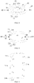
FIG. 1 is a structure diagram, after assembly, of an aerosol generating device according to one embodiment, -
FIG. 2 is a sectional view of a heating mechanism in the aerosol generating device shown inFIG. 1 . -
FIG. 3 is a sectional view of the heating mechanism shown inFIG. 2 moved to a second position. -
FIG. 4 is a structure diagram of a retaining mechanism in the heating mechanism shown inFIG. 2 -
FIG. 5 is a diagram of a first infrared emitter according to another embodiment. -
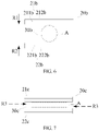
FIG. 6 is a sectional view of a heating mechanism according to another embodiment. -
FIG. 7 is a diagram of a smokable material according to another embodiment. - The present disclosure will become better understood from a detailed description of the present disclosure below taken in conjunction with drawings and particular embodiments.
- One embodiment of the present disclosure provides an aerosol generating device which heats rather than burns a smokable material such as a cigarette, so that at least one ingredient of the smokable material is volatilized or released to form an aerosol for inhalation.
- In a preferred embodiment, the aerosol generating device heats the smokable material by radiating far infrared rays having a heating effect, for example, far infrared rays of 3µm to 15µm; during operation, when the wavelength of the infrared rays matches with the wavelength absorbable by the volatile ingredient of the smokable material, the energy of the infrared rays is easy to be absorbed by the smokable material, thus the smokable material is heated so that at least one volatile ingredient is volatilized to generate an aerosol for inhalation.
- The aerosol generating device according to one embodiment of the present disclosure can refer to
FIG. 1 in structure, the overall shape of the device is roughly configured as a tabular tube, and external components of the aerosol generating device include: - a
shell 10, which is configured to be hollow inside, thereby forming an assembly space for necessary functional components such as infrared radiation; theshell 10 includes aproximal end 110 and adistal end 120 that are opposite in the length direction, wherein - the
proximal end 110 defines areceiving hole 111, and through thereceiving hole 111, a smokable material A may be received within theshell 10 to be heated or may be removed from theshell 10. - To heat the smokable material A received within the
shell 10 through radiation of infrared rays, further, theshell 10 is internally provided with aninfrared emitter 20 for heating; in one embodiment, the structure can refer toFIG. 2 to FIG. 3 , including: - the
shell 10 is internally provided with achamber 30 configured to receive a smokable material A; - the
infrared emitter 20 includes a firstinfrared emitter 21 and a secondinfrared emitter 22 that are arranged surrounding thechamber 30; specifically, according to the structure shown in figures, the firstinfrared emitter 21 and the secondinfrared emitter 22 are totally the same in structure and content, both including two parts: - a
base portion 211/221, which as a rigid support substrate material may be made of high-temperature resistant and infrared transmissive materials such as quartz glass, ceramic, mica, etc. during implementations; and - an
infrared emitting coating 212/222 formed on thebase portion 211/221, wherein theinfrared emitting coating 212/222 is capable of generating heat when electrified, thereby radiating infrared rays that can be used to heat the smokable material A, for example, the above far infrared rays of 3µm to 15µm. When the wavelength of the infrared rays matches with the wavelength absorbable by the volatile ingredient of the smokable material, the energy of the infrared rays is easy to be absorbed by the smokable material. - Generally, during implementations, the
infrared emitting coating 212/222 may be a coating made of ceramic materials such as zirconium, or Fe-Mn-Cu series, tungsten series, or transition metals and their oxide materials. - In a preferred embodiment, the infrared emitting
coating 212/222 preferably is composed of an oxide of at least one metallic element among Mg, Al, Ti, Zr, Mn, Fe, Co, Ni, Cu, Cr, Zn, etc.; these metallic oxides when heated to an appropriate temperature can radiate far infrared rays having a heating effect; the thickness of the coating preferably may be controlled between 30µm to 50µm; the formation mode on the surface of thebase portion 211/221 may be achieved by spraying the oxides of the above metallic elements on the outer surface of thebase portion 211/221 through an atmospheric plasma spraying method and then curing it, that is, obtaining an infrared emitting film bonded to the surface of the base. - The above first
infrared emitter 21 and secondinfrared emitter 22, as shown in figures, are configured as a curved shape in cross section, such that it is easy to form theinfrared emitting coating 212/222 on surfaces thereof respectively. - Further, in a preferred embodiment, the first
infrared emitter 21 and the secondinfrared emitter 22 may be supplied with power or controlled separately, so that they can radiate infrared rays independently to heat different portions of the smokable material A. Specifically, in an optional control manner, the firstinfrared emitter 21 and the secondinfrared emitter 22 may be started alternately or at the same time. - Further, according to the embodiments of the heating state shown in
FIG. 2 to FIG. 4 , thechamber 30 is configured as a tabular shape, specifically an oval shape inFIG. 2 , that is, the size in the vertical direction r1 is less than the size in the horizontal direction r2, such that the firstinfrared emitter 21 and the secondinfrared emitter 22 have a relative greater area of radiation for the smokable material A. - Further, in a preferred embodiment, the first
infrared emitter 21 and the secondinfrared emitter 22 are separated from each other and may move relative to each other, specifically referring toFIG. 2 to FIG. 3 . - As shown in
FIG. 2 , the firstinfrared emitter 21 and the secondinfrared emitter 22 are located at the first position, under which condition the smokable material A is received within thechamber 30 and basically keeps its own shape, generally the smokable material is shaped as a cylinder with a circular cross section according to product preparation and familiar structures. - From
FIG. 2 , the firstinfrared emitter 21 and the secondinfrared emitter 22 approach each other along directions indicated by arrows R1 and R2 shown inFIG. 2 respectively, until reaching the second position shown inFIG. 3 ; when at the second position, the firstinfrared emitter 21 and the secondinfrared emitter 22 enclose and squeeze the smokable material A respectively, so that the smokable material deforms, wherein the smokable material roughly may be squeezed into the shape of a cylinder with an oval cross section, as shown inFIG. 3 ; by the time, start the firstinfrared emitter 21 and the secondinfrared emitter 22, then the distance between the radiated infrared rays and the internal center 0 of the smokable material A is greatly reduced, thereby increasing the ability and efficiency of absorbing infrared rays inside the smokable material A compared to the state shown inFIG. 2 , such that a surface layer and the interior of the smokable material A can be relatively uniformly heated. - To facilitate the operation of relative movement between the first
infrared emitter 21 and the secondinfrared emitter 22, in the preferred embodiments shown inFIG. 2 andFIG. 3 , theshell 10 is internally provided with a biasing element, which is configured to bias the first infrared emitter towards the second position. Specifically, the biasing element includes afirst spring 41 and asecond spring 42 which, after being stretched as shown inFIG. 3 , provide an elastic restoring force so that the firstinfrared emitter 21 and the secondinfrared emitter 22 are biased towards the first position shown inFIG. 2 , facilitating the removal of the smokable material A after the inhalation is completed. - Of course, further, in an optional embodiment, to enable the first
infrared emitter 21 and the secondinfrared emitter 22 to be stably retained at different positions respectively, theshell 10 is internally provided with a retaining mechanism, for example, afirst retaining element 51 located on the firstinfrared emitter 21 as shown inFIG. 4 , for example, a mechanical connection mechanism such as a magnet, a fastener, etc., and asecond retaining element 52 which may be located on the secondinfrared emitter 22 and may cooperate with the first retainingelement 51 to form securing or connection, so that the first retainingelement 51 may be retained at different positions. - In another variant embodiment as shown in
FIG. 5 , the infrared emittingcoating 212a of the firstinfrared emitter 21a is formed on an outer surface away from thechamber 30, or is an infrared emitting film wrapped around an outer surface of the firstinfrared emitter 21a away from thechamber 30, for example, a zinc oxide film, a graphene film, an indium oxide film doped with rare earth metals, etc. Meanwhile, to facilitate power supply to the infrared emittingcoating 212a so that it radiates infrared rays, upper and lower ends of the outer surface of the firstinfrared emitter 21a are formed, respectively, with a firstconductive coating 213a and a secondconductive coating 214a which are made of silver, gold or copper, etc., and have an excellent conductivity; and subsequently the conductive coating is connected to a power supply device through welding a lead or sleeving a conductive ring and so on, so as to supply power to the infrared emittingcoating 212a. - Further, in a variant embodiment, the structure of the
infrared emitter 20b may refer toFIG. 6 , including:
a firstinfrared emitter 21b and a secondinfrared emitter 22b that are configured as the shape of a sheet, wherein the firstinfrared emitter 21b and the secondinfrared emitter 22b are arranged at two opposite sides of thechamber 30b, and they can move relative to each other to squeeze the smokable material A received within thechamber 30b, so that the smokable material A is squeezed into the oval shape shown inFIG. 3 to increase the efficiency of the infrared rays penetrating into the center, such that a surface layer and the interior of the smokable material A can be relatively uniformly heated. - In another variant embodiment, as shown in
FIG. 7 , the smokable material A is configured as the shape of a block or sheet, different from the shape of conventional cylinders; the first infrared emitter 21C and the secondinfrared emitter 22c of theinfrared emitter 20c are oppositely arranged in the thickness direction of the smokable material A respectively, so that the block shaped smokable material A adapted to thechamber 30c may have a greater surface area to increase the efficiency of absorbing infrared rays, thereby improving the heating efficiency and enabling a surface layer and the interior of the smokable material A to be relatively uniformly heated. - During the smoking process of the above aerosol generating device, as indicated by the arrows R3 shown in
FIG. 3, FIG. 4 orFIG. 7 , external air may enter thechamber 30/30c from two sides thereof via the space between the firstinfrared emitter 21/21c and the secondinfrared emitter 22/22c, until passing through the smokable material A to be inhaled. - It is to be noted that the description of the present disclosure and the drawings just list preferred embodiments of the present disclosure and are not limited to the embodiments described herein. Further, for the ordinary staff in this field, improvements or variations may be made according to the above description, and all these improvements or variations are intended to be included within the scope of protection of the claims appended hereinafter.
Claims (10)
- An aerosol generating device, configured to heat a smokable material to generate an aerosol for inhalation, comprising:a chamber, configured to receive a smokable material;the chamber having a first radial direction, and a second radial direction that is perpendicular to the first radial direction; anda first infrared emitter and a second infrared emitter that are arranged in the first radial direction of the chamber and configured to radiate infrared rays towards the chamber so as to heat the smokable material, the first infrared emitter and the second infrared emitter extending at least partially in the second radial direction, thereby defining the chamber between the first infrared emitter and the second infrared emitter, such that the size of the chamber in the second radial direction is greater than that in the first radial direction.
- The aerosol generating device according to claim 1, wherein the first infrared emitter and the second infrared emitter are separated from each other.
- The aerosol generating device according to claim 1, wherein the first infrared emitter and the second infrared emitter are spaced with certain distance, to form an airflow channel for external air to enter the chamber.
- The aerosol generating device according to any one of claim 1 to 3, wherein the first infrared emitter is configured to be able to move in the first radial direction relative to the second infrared emitter, to change the size of the chamber in the first radial direction.
- The aerosol generating device according to claim 4, wherein the first infrared emitter has a first position and a second position opposite to the second infrared emitter, and is able to move between the first position and the second position in the first radial direction relative to the second infrared emitter; wherein
the size of the chamber in the first radial direction when the first infrared emitter is at the first position is less than the size of the chamber in the first radial direction when the first infrared emitter is at the second position. - The aerosol generating device according to claim 5, further comprising a retaining mechanism, which is configured to stably retain the first infrared emitter at the first position and/or the second position.
- The aerosol generating device according to claim 5, further comprising a biasing element, which is configured to bias the first infrared emitter towards the second position.
- The aerosol generating device according to any one of claims 1 to 3, wherein the first infrared emitter and/or the second infrared emitter are/is configured as the shape of a sheet extending in the second radial direction.
- The aerosol generating device according to any one of claims 1 to 3, wherein the first infrared emitter and/or the second infrared emitter are/is configured as the shape of a curve bending outwards in the first radial direction of the chamber.
- The aerosol generating device according to any one of claims 1 to 3, wherein the first infrared emitter or the second infrared emitter comprises:a base; and,an infrared emitting coating formed on a surface of the base or an infrared emitting film bonded to a surface of the base.
Applications Claiming Priority (2)
| Application Number | Priority Date | Filing Date | Title |
|---|---|---|---|
| CN202010048160.9A CN113115997A (en) | 2020-01-16 | 2020-01-16 | Aerosol generator |
| PCT/CN2021/072136 WO2021143837A1 (en) | 2020-01-16 | 2021-01-15 | Aerosol generating device and heater |
Publications (3)
| Publication Number | Publication Date |
|---|---|
| EP4091487A1 true EP4091487A1 (en) | 2022-11-23 |
| EP4091487A4 EP4091487A4 (en) | 2023-06-28 |
| EP4091487B1 EP4091487B1 (en) | 2024-05-01 |
Family
ID=76771951
Family Applications (1)
| Application Number | Title | Priority Date | Filing Date |
|---|---|---|---|
| EP21741505.8A Active EP4091487B1 (en) | 2020-01-16 | 2021-01-15 | Aerosol generating device and heater |
Country Status (4)
| Country | Link |
|---|---|
| US (1) | US20230128317A1 (en) |
| EP (1) | EP4091487B1 (en) |
| CN (1) | CN113115997A (en) |
| WO (1) | WO2021143837A1 (en) |
Families Citing this family (1)
| Publication number | Priority date | Publication date | Assignee | Title |
|---|---|---|---|---|
| EP4408213A1 (en) * | 2021-09-27 | 2024-08-07 | Imperial Tobacco Limited | Aerosol delivery article with an infrared heater |
Family Cites Families (15)
| Publication number | Priority date | Publication date | Assignee | Title |
|---|---|---|---|---|
| US20140314396A1 (en) * | 2013-04-22 | 2014-10-23 | Chih-Ming Hsu | Electrothermal element |
| US20160249413A1 (en) * | 2015-02-23 | 2016-08-25 | Electronics And Telecommunications Research Institute | Transparent planar heater |
| CN109068754A (en) * | 2016-05-31 | 2018-12-21 | 菲利普莫里斯生产公司 | Product is generated with tubulose aerosol and the electrically operated aerosol of feature is kept to generate system |
| EP3574710B1 (en) * | 2017-01-25 | 2022-03-16 | Nicoventures Trading Limited | Apparatus for heating smokable material |
| CN108338416B (en) * | 2017-01-25 | 2022-05-31 | 贵州中烟工业有限责任公司 | Inner core heated smoking system |
| GB201721477D0 (en) * | 2017-12-20 | 2018-01-31 | British American Tobacco Investments Ltd | Electronic aerosol provision system |
| CN209120496U (en) * | 2018-08-21 | 2019-07-16 | 深圳市子午线信息科技有限公司 | A kind of heating device based on nano-far-infrared |
| CN108741237B (en) * | 2018-08-28 | 2023-10-20 | 北京智新物码信息技术有限公司 | Three-dimensional electric heating non-combustion equipment |
| CN109043673B (en) * | 2018-08-28 | 2024-02-09 | 北京智新物码信息技术有限公司 | Heating non-combustion equipment |
| CN108887749B (en) * | 2018-08-28 | 2024-02-27 | 北京智新物码信息技术有限公司 | Heating non-combustion equipment of adaptation heating thing |
| CN109007978B (en) * | 2018-08-28 | 2023-10-20 | 北京智新物码信息技术有限公司 | Environment-friendly heating non-combustion equipment |
| CN109077358A (en) * | 2018-09-19 | 2018-12-25 | 深圳市子午线信息科技有限公司 | Based on nano-far-infrared subsection heating device and electronic cigarette |
| CN109876253B (en) * | 2019-01-10 | 2023-10-27 | 深圳市特眸智能控制系统有限公司 | Heating device and sucking device |
| CN110384264A (en) * | 2019-07-15 | 2019-10-29 | 深圳市合元科技有限公司 | Heater and low-temperature heat smoking set |
| CN110495649A (en) * | 2019-10-08 | 2019-11-26 | 昆山联滔电子有限公司 | Cigarette holding heating device and electronic cigarette using the same |
-
2020
- 2020-01-16 CN CN202010048160.9A patent/CN113115997A/en active Pending
-
2021
- 2021-01-15 EP EP21741505.8A patent/EP4091487B1/en active Active
- 2021-01-15 WO PCT/CN2021/072136 patent/WO2021143837A1/en not_active Ceased
- 2021-01-15 US US17/758,883 patent/US20230128317A1/en active Pending
Also Published As
| Publication number | Publication date |
|---|---|
| WO2021143837A1 (en) | 2021-07-22 |
| US20230128317A1 (en) | 2023-04-27 |
| CN113115997A (en) | 2021-07-16 |
| EP4091487A4 (en) | 2023-06-28 |
| EP4091487B1 (en) | 2024-05-01 |
Similar Documents
| Publication | Publication Date | Title |
|---|---|---|
| JP7625748B2 (en) | Aerosol generating device and heating chamber therefor | |
| CN211910548U (en) | Aerosol generator and heater | |
| EP4218449A1 (en) | Aerosol generation device and infrared heater | |
| EP4218441A1 (en) | Aerosol generating device | |
| US20240180247A1 (en) | Vapor generation device and resistance heater for vapor generation device | |
| TW202019303A (en) | Aerosol generating device and its heating cavity | |
| CN211910542U (en) | Aerosol generating device and heating mechanism for aerosol generating device | |
| EP4088596A1 (en) | Aerosol generating device | |
| EP4082361A1 (en) | Heater and cigarette utensil containing same | |
| EP4241589A1 (en) | Aerosol generating device | |
| UA120511C2 (en) | PRODUCT GENERATING AEROSOL WITH INTERNAL CURRENT RECEIVER | |
| KR20190047103A (en) | An aerosol-generating article having an improved outermost wrapper | |
| CN211910545U (en) | Aerosol generating device and infrared emitter for aerosol generating device | |
| EP4717102A1 (en) | Aerosol generating device, and heater for aerosol generating device | |
| EP4218448A1 (en) | Aerosol generation device and infrared heater | |
| US12349729B2 (en) | Aerosol-generating device and infrared emitter | |
| EP4091487B1 (en) | Aerosol generating device and heater | |
| CN219422196U (en) | Aerosol generating device and heating structure thereof | |
| EP4091475A1 (en) | Aerosol-producing product and aerosol-generating system | |
| WO2024055719A1 (en) | Heating assembly and aerosol generation device | |
| WO2021143840A1 (en) | Aerosol generation apparatus and infrared emitter | |
| JP2023540937A (en) | Aerosol-generating articles and aerosol-generating systems | |
| CN221962870U (en) | Aerosol generating device | |
| WO2025176008A1 (en) | Heating assembly and aerosol generating device | |
| TWI925038B (en) | Aerosol generating device, heating assembly for aerosol generating device and method of manufacturing the heating assembly |
Legal Events
| Date | Code | Title | Description |
|---|---|---|---|
| STAA | Information on the status of an ep patent application or granted ep patent |
Free format text: STATUS: THE INTERNATIONAL PUBLICATION HAS BEEN MADE |
|
| PUAI | Public reference made under article 153(3) epc to a published international application that has entered the european phase |
Free format text: ORIGINAL CODE: 0009012 |
|
| STAA | Information on the status of an ep patent application or granted ep patent |
Free format text: STATUS: REQUEST FOR EXAMINATION WAS MADE |
|
| 17P | Request for examination filed |
Effective date: 20220715 |
|
| AK | Designated contracting states |
Kind code of ref document: A1 Designated state(s): AL AT BE BG CH CY CZ DE DK EE ES FI FR GB GR HR HU IE IS IT LI LT LU LV MC MK MT NL NO PL PT RO RS SE SI SK SM TR |
|
| DAV | Request for validation of the european patent (deleted) | ||
| DAX | Request for extension of the european patent (deleted) | ||
| REG | Reference to a national code |
Ref country code: DE Ref legal event code: R079 Free format text: PREVIOUS MAIN CLASS: A24F0047000000 Ipc: A24F0040460000 Ref document number: 602021012796 Country of ref document: DE |
|
| A4 | Supplementary search report drawn up and despatched |
Effective date: 20230526 |
|
| RIC1 | Information provided on ipc code assigned before grant |
Ipc: A24F 40/20 20200101ALN20230522BHEP Ipc: A24F 40/46 20200101AFI20230522BHEP |
|
| RIC1 | Information provided on ipc code assigned before grant |
Ipc: A24F 40/20 20200101ALN20231026BHEP Ipc: A24F 40/46 20200101AFI20231026BHEP |
|
| GRAP | Despatch of communication of intention to grant a patent |
Free format text: ORIGINAL CODE: EPIDOSNIGR1 |
|
| STAA | Information on the status of an ep patent application or granted ep patent |
Free format text: STATUS: GRANT OF PATENT IS INTENDED |
|
| INTG | Intention to grant announced |
Effective date: 20231206 |
|
| GRAS | Grant fee paid |
Free format text: ORIGINAL CODE: EPIDOSNIGR3 |
|
| GRAA | (expected) grant |
Free format text: ORIGINAL CODE: 0009210 |
|
| STAA | Information on the status of an ep patent application or granted ep patent |
Free format text: STATUS: THE PATENT HAS BEEN GRANTED |
|
| AK | Designated contracting states |
Kind code of ref document: B1 Designated state(s): AL AT BE BG CH CY CZ DE DK EE ES FI FR GB GR HR HU IE IS IT LI LT LU LV MC MK MT NL NO PL PT RO RS SE SI SK SM TR |
|
| REG | Reference to a national code |
Ref country code: GB Ref legal event code: FG4D |
|
| REG | Reference to a national code |
Ref country code: CH Ref legal event code: EP |
|
| REG | Reference to a national code |
Ref country code: IE Ref legal event code: FG4D |
|
| REG | Reference to a national code |
Ref country code: DE Ref legal event code: R096 Ref document number: 602021012796 Country of ref document: DE |
|
| REG | Reference to a national code |
Ref country code: LT Ref legal event code: MG9D |
|
| REG | Reference to a national code |
Ref country code: NL Ref legal event code: MP Effective date: 20240501 |
|
| PG25 | Lapsed in a contracting state [announced via postgrant information from national office to epo] |
Ref country code: IS Free format text: LAPSE BECAUSE OF FAILURE TO SUBMIT A TRANSLATION OF THE DESCRIPTION OR TO PAY THE FEE WITHIN THE PRESCRIBED TIME-LIMIT Effective date: 20240901 |
|
| PG25 | Lapsed in a contracting state [announced via postgrant information from national office to epo] |
Ref country code: BG Free format text: LAPSE BECAUSE OF FAILURE TO SUBMIT A TRANSLATION OF THE DESCRIPTION OR TO PAY THE FEE WITHIN THE PRESCRIBED TIME-LIMIT Effective date: 20240501 |
|
| PG25 | Lapsed in a contracting state [announced via postgrant information from national office to epo] |
Ref country code: FI Free format text: LAPSE BECAUSE OF FAILURE TO SUBMIT A TRANSLATION OF THE DESCRIPTION OR TO PAY THE FEE WITHIN THE PRESCRIBED TIME-LIMIT Effective date: 20240501 Ref country code: HR Free format text: LAPSE BECAUSE OF FAILURE TO SUBMIT A TRANSLATION OF THE DESCRIPTION OR TO PAY THE FEE WITHIN THE PRESCRIBED TIME-LIMIT Effective date: 20240501 |
|
| PG25 | Lapsed in a contracting state [announced via postgrant information from national office to epo] |
Ref country code: GR Free format text: LAPSE BECAUSE OF FAILURE TO SUBMIT A TRANSLATION OF THE DESCRIPTION OR TO PAY THE FEE WITHIN THE PRESCRIBED TIME-LIMIT Effective date: 20240802 |
|
| PG25 | Lapsed in a contracting state [announced via postgrant information from national office to epo] |
Ref country code: PT Free format text: LAPSE BECAUSE OF FAILURE TO SUBMIT A TRANSLATION OF THE DESCRIPTION OR TO PAY THE FEE WITHIN THE PRESCRIBED TIME-LIMIT Effective date: 20240902 |
|
| REG | Reference to a national code |
Ref country code: AT Ref legal event code: MK05 Ref document number: 1681112 Country of ref document: AT Kind code of ref document: T Effective date: 20240501 |
|
| PG25 | Lapsed in a contracting state [announced via postgrant information from national office to epo] |
Ref country code: NL Free format text: LAPSE BECAUSE OF FAILURE TO SUBMIT A TRANSLATION OF THE DESCRIPTION OR TO PAY THE FEE WITHIN THE PRESCRIBED TIME-LIMIT Effective date: 20240501 |
|
| PG25 | Lapsed in a contracting state [announced via postgrant information from national office to epo] |
Ref country code: ES Free format text: LAPSE BECAUSE OF FAILURE TO SUBMIT A TRANSLATION OF THE DESCRIPTION OR TO PAY THE FEE WITHIN THE PRESCRIBED TIME-LIMIT Effective date: 20240501 |
|
| PG25 | Lapsed in a contracting state [announced via postgrant information from national office to epo] |
Ref country code: AT Free format text: LAPSE BECAUSE OF FAILURE TO SUBMIT A TRANSLATION OF THE DESCRIPTION OR TO PAY THE FEE WITHIN THE PRESCRIBED TIME-LIMIT Effective date: 20240501 |
|
| PG25 | Lapsed in a contracting state [announced via postgrant information from national office to epo] |
Ref country code: PL Free format text: LAPSE BECAUSE OF FAILURE TO SUBMIT A TRANSLATION OF THE DESCRIPTION OR TO PAY THE FEE WITHIN THE PRESCRIBED TIME-LIMIT Effective date: 20240501 |
|
| PG25 | Lapsed in a contracting state [announced via postgrant information from national office to epo] |
Ref country code: LV Free format text: LAPSE BECAUSE OF FAILURE TO SUBMIT A TRANSLATION OF THE DESCRIPTION OR TO PAY THE FEE WITHIN THE PRESCRIBED TIME-LIMIT Effective date: 20240501 |
|
| PG25 | Lapsed in a contracting state [announced via postgrant information from national office to epo] |
Ref country code: PT Free format text: LAPSE BECAUSE OF FAILURE TO SUBMIT A TRANSLATION OF THE DESCRIPTION OR TO PAY THE FEE WITHIN THE PRESCRIBED TIME-LIMIT Effective date: 20240902 Ref country code: PL Free format text: LAPSE BECAUSE OF FAILURE TO SUBMIT A TRANSLATION OF THE DESCRIPTION OR TO PAY THE FEE WITHIN THE PRESCRIBED TIME-LIMIT Effective date: 20240501 Ref country code: NO Free format text: LAPSE BECAUSE OF FAILURE TO SUBMIT A TRANSLATION OF THE DESCRIPTION OR TO PAY THE FEE WITHIN THE PRESCRIBED TIME-LIMIT Effective date: 20240801 Ref country code: NL Free format text: LAPSE BECAUSE OF FAILURE TO SUBMIT A TRANSLATION OF THE DESCRIPTION OR TO PAY THE FEE WITHIN THE PRESCRIBED TIME-LIMIT Effective date: 20240501 Ref country code: LV Free format text: LAPSE BECAUSE OF FAILURE TO SUBMIT A TRANSLATION OF THE DESCRIPTION OR TO PAY THE FEE WITHIN THE PRESCRIBED TIME-LIMIT Effective date: 20240501 Ref country code: IS Free format text: LAPSE BECAUSE OF FAILURE TO SUBMIT A TRANSLATION OF THE DESCRIPTION OR TO PAY THE FEE WITHIN THE PRESCRIBED TIME-LIMIT Effective date: 20240901 Ref country code: HR Free format text: LAPSE BECAUSE OF FAILURE TO SUBMIT A TRANSLATION OF THE DESCRIPTION OR TO PAY THE FEE WITHIN THE PRESCRIBED TIME-LIMIT Effective date: 20240501 Ref country code: GR Free format text: LAPSE BECAUSE OF FAILURE TO SUBMIT A TRANSLATION OF THE DESCRIPTION OR TO PAY THE FEE WITHIN THE PRESCRIBED TIME-LIMIT Effective date: 20240802 Ref country code: FI Free format text: LAPSE BECAUSE OF FAILURE TO SUBMIT A TRANSLATION OF THE DESCRIPTION OR TO PAY THE FEE WITHIN THE PRESCRIBED TIME-LIMIT Effective date: 20240501 Ref country code: ES Free format text: LAPSE BECAUSE OF FAILURE TO SUBMIT A TRANSLATION OF THE DESCRIPTION OR TO PAY THE FEE WITHIN THE PRESCRIBED TIME-LIMIT Effective date: 20240501 Ref country code: BG Free format text: LAPSE BECAUSE OF FAILURE TO SUBMIT A TRANSLATION OF THE DESCRIPTION OR TO PAY THE FEE WITHIN THE PRESCRIBED TIME-LIMIT Effective date: 20240501 Ref country code: AT Free format text: LAPSE BECAUSE OF FAILURE TO SUBMIT A TRANSLATION OF THE DESCRIPTION OR TO PAY THE FEE WITHIN THE PRESCRIBED TIME-LIMIT Effective date: 20240501 Ref country code: RS Free format text: LAPSE BECAUSE OF FAILURE TO SUBMIT A TRANSLATION OF THE DESCRIPTION OR TO PAY THE FEE WITHIN THE PRESCRIBED TIME-LIMIT Effective date: 20240801 |
|
| PG25 | Lapsed in a contracting state [announced via postgrant information from national office to epo] |
Ref country code: DK Free format text: LAPSE BECAUSE OF FAILURE TO SUBMIT A TRANSLATION OF THE DESCRIPTION OR TO PAY THE FEE WITHIN THE PRESCRIBED TIME-LIMIT Effective date: 20240501 |
|
| PG25 | Lapsed in a contracting state [announced via postgrant information from national office to epo] |
Ref country code: EE Free format text: LAPSE BECAUSE OF FAILURE TO SUBMIT A TRANSLATION OF THE DESCRIPTION OR TO PAY THE FEE WITHIN THE PRESCRIBED TIME-LIMIT Effective date: 20240501 |
|
| PG25 | Lapsed in a contracting state [announced via postgrant information from national office to epo] |
Ref country code: CZ Free format text: LAPSE BECAUSE OF FAILURE TO SUBMIT A TRANSLATION OF THE DESCRIPTION OR TO PAY THE FEE WITHIN THE PRESCRIBED TIME-LIMIT Effective date: 20240501 |
|
| PG25 | Lapsed in a contracting state [announced via postgrant information from national office to epo] |
Ref country code: SK Free format text: LAPSE BECAUSE OF FAILURE TO SUBMIT A TRANSLATION OF THE DESCRIPTION OR TO PAY THE FEE WITHIN THE PRESCRIBED TIME-LIMIT Effective date: 20240501 Ref country code: RO Free format text: LAPSE BECAUSE OF FAILURE TO SUBMIT A TRANSLATION OF THE DESCRIPTION OR TO PAY THE FEE WITHIN THE PRESCRIBED TIME-LIMIT Effective date: 20240501 |
|
| PG25 | Lapsed in a contracting state [announced via postgrant information from national office to epo] |
Ref country code: SM Free format text: LAPSE BECAUSE OF FAILURE TO SUBMIT A TRANSLATION OF THE DESCRIPTION OR TO PAY THE FEE WITHIN THE PRESCRIBED TIME-LIMIT Effective date: 20240501 |
|
| PG25 | Lapsed in a contracting state [announced via postgrant information from national office to epo] |
Ref country code: SM Free format text: LAPSE BECAUSE OF FAILURE TO SUBMIT A TRANSLATION OF THE DESCRIPTION OR TO PAY THE FEE WITHIN THE PRESCRIBED TIME-LIMIT Effective date: 20240501 Ref country code: SK Free format text: LAPSE BECAUSE OF FAILURE TO SUBMIT A TRANSLATION OF THE DESCRIPTION OR TO PAY THE FEE WITHIN THE PRESCRIBED TIME-LIMIT Effective date: 20240501 Ref country code: RO Free format text: LAPSE BECAUSE OF FAILURE TO SUBMIT A TRANSLATION OF THE DESCRIPTION OR TO PAY THE FEE WITHIN THE PRESCRIBED TIME-LIMIT Effective date: 20240501 Ref country code: EE Free format text: LAPSE BECAUSE OF FAILURE TO SUBMIT A TRANSLATION OF THE DESCRIPTION OR TO PAY THE FEE WITHIN THE PRESCRIBED TIME-LIMIT Effective date: 20240501 Ref country code: DK Free format text: LAPSE BECAUSE OF FAILURE TO SUBMIT A TRANSLATION OF THE DESCRIPTION OR TO PAY THE FEE WITHIN THE PRESCRIBED TIME-LIMIT Effective date: 20240501 Ref country code: CZ Free format text: LAPSE BECAUSE OF FAILURE TO SUBMIT A TRANSLATION OF THE DESCRIPTION OR TO PAY THE FEE WITHIN THE PRESCRIBED TIME-LIMIT Effective date: 20240501 |
|
| REG | Reference to a national code |
Ref country code: DE Ref legal event code: R097 Ref document number: 602021012796 Country of ref document: DE |
|
| PG25 | Lapsed in a contracting state [announced via postgrant information from national office to epo] |
Ref country code: IT Free format text: LAPSE BECAUSE OF FAILURE TO SUBMIT A TRANSLATION OF THE DESCRIPTION OR TO PAY THE FEE WITHIN THE PRESCRIBED TIME-LIMIT Effective date: 20240501 |
|
| PLBE | No opposition filed within time limit |
Free format text: ORIGINAL CODE: 0009261 |
|
| STAA | Information on the status of an ep patent application or granted ep patent |
Free format text: STATUS: NO OPPOSITION FILED WITHIN TIME LIMIT |
|
| 26N | No opposition filed |
Effective date: 20250204 |
|
| P01 | Opt-out of the competence of the unified patent court (upc) registered |
Free format text: CASE NUMBER: APP_11091/2025 Effective date: 20250306 |
|
| PG25 | Lapsed in a contracting state [announced via postgrant information from national office to epo] |
Ref country code: SI Free format text: LAPSE BECAUSE OF FAILURE TO SUBMIT A TRANSLATION OF THE DESCRIPTION OR TO PAY THE FEE WITHIN THE PRESCRIBED TIME-LIMIT Effective date: 20240501 |
|
| REG | Reference to a national code |
Ref country code: CH Ref legal event code: PL |
|
| PG25 | Lapsed in a contracting state [announced via postgrant information from national office to epo] |
Ref country code: SE Free format text: LAPSE BECAUSE OF FAILURE TO SUBMIT A TRANSLATION OF THE DESCRIPTION OR TO PAY THE FEE WITHIN THE PRESCRIBED TIME-LIMIT Effective date: 20240501 |
|
| PG25 | Lapsed in a contracting state [announced via postgrant information from national office to epo] |
Ref country code: MC Free format text: LAPSE BECAUSE OF FAILURE TO SUBMIT A TRANSLATION OF THE DESCRIPTION OR TO PAY THE FEE WITHIN THE PRESCRIBED TIME-LIMIT Effective date: 20240501 Ref country code: LU Free format text: LAPSE BECAUSE OF NON-PAYMENT OF DUE FEES Effective date: 20250115 |
|
| PG25 | Lapsed in a contracting state [announced via postgrant information from national office to epo] |
Ref country code: BE Free format text: LAPSE BECAUSE OF NON-PAYMENT OF DUE FEES Effective date: 20250131 |
|
| PG25 | Lapsed in a contracting state [announced via postgrant information from national office to epo] |
Ref country code: CH Free format text: LAPSE BECAUSE OF NON-PAYMENT OF DUE FEES Effective date: 20250131 |
|
| REG | Reference to a national code |
Ref country code: BE Ref legal event code: MM Effective date: 20250131 |
|
| PG25 | Lapsed in a contracting state [announced via postgrant information from national office to epo] |
Ref country code: IE Free format text: LAPSE BECAUSE OF NON-PAYMENT OF DUE FEES Effective date: 20250115 |
|
| PGFP | Annual fee paid to national office [announced via postgrant information from national office to epo] |
Ref country code: GB Payment date: 20260127 Year of fee payment: 6 |
|
| PGFP | Annual fee paid to national office [announced via postgrant information from national office to epo] |
Ref country code: DE Payment date: 20260114 Year of fee payment: 6 |
|
| PGFP | Annual fee paid to national office [announced via postgrant information from national office to epo] |
Ref country code: FR Payment date: 20260128 Year of fee payment: 6 |