EP4091478A1 - Aerosol generating device and heater - Google Patents
Aerosol generating device and heater Download PDFInfo
- Publication number
- EP4091478A1 EP4091478A1 EP21741578.5A EP21741578A EP4091478A1 EP 4091478 A1 EP4091478 A1 EP 4091478A1 EP 21741578 A EP21741578 A EP 21741578A EP 4091478 A1 EP4091478 A1 EP 4091478A1
- Authority
- EP
- European Patent Office
- Prior art keywords
- infrared emission
- susceptor
- generating device
- aerosol generating
- cavity
- Prior art date
- Legal status (The legal status is an assumption and is not a legal conclusion. Google has not performed a legal analysis and makes no representation as to the accuracy of the status listed.)
- Granted
Links
Images



Classifications
-
- A—HUMAN NECESSITIES
- A24—TOBACCO; CIGARS; CIGARETTES; SIMULATED SMOKING DEVICES; SMOKERS' REQUISITES
- A24F—SMOKERS' REQUISITES; MATCH BOXES; SIMULATED SMOKING DEVICES
- A24F40/00—Electrically operated smoking devices; Component parts thereof; Manufacture thereof; Maintenance or testing thereof; Charging means specially adapted therefor
- A24F40/40—Constructional details, e.g. connection of cartridges and battery parts
- A24F40/46—Shape or structure of electric heating means
- A24F40/465—Shape or structure of electric heating means specially adapted for induction heating
-
- A—HUMAN NECESSITIES
- A24—TOBACCO; CIGARS; CIGARETTES; SIMULATED SMOKING DEVICES; SMOKERS' REQUISITES
- A24F—SMOKERS' REQUISITES; MATCH BOXES; SIMULATED SMOKING DEVICES
- A24F40/00—Electrically operated smoking devices; Component parts thereof; Manufacture thereof; Maintenance or testing thereof; Charging means specially adapted therefor
- A24F40/40—Constructional details, e.g. connection of cartridges and battery parts
-
- A—HUMAN NECESSITIES
- A24—TOBACCO; CIGARS; CIGARETTES; SIMULATED SMOKING DEVICES; SMOKERS' REQUISITES
- A24F—SMOKERS' REQUISITES; MATCH BOXES; SIMULATED SMOKING DEVICES
- A24F40/00—Electrically operated smoking devices; Component parts thereof; Manufacture thereof; Maintenance or testing thereof; Charging means specially adapted therefor
- A24F40/40—Constructional details, e.g. connection of cartridges and battery parts
- A24F40/46—Shape or structure of electric heating means
-
- A—HUMAN NECESSITIES
- A24—TOBACCO; CIGARS; CIGARETTES; SIMULATED SMOKING DEVICES; SMOKERS' REQUISITES
- A24F—SMOKERS' REQUISITES; MATCH BOXES; SIMULATED SMOKING DEVICES
- A24F40/00—Electrically operated smoking devices; Component parts thereof; Manufacture thereof; Maintenance or testing thereof; Charging means specially adapted therefor
- A24F40/50—Control or monitoring
- A24F40/51—Arrangement of sensors
-
- F—MECHANICAL ENGINEERING; LIGHTING; HEATING; WEAPONS; BLASTING
- F28—HEAT EXCHANGE IN GENERAL
- F28F—DETAILS OF HEAT-EXCHANGE AND HEAT-TRANSFER APPARATUS, OF GENERAL APPLICATION
- F28F13/00—Arrangements for modifying heat-transfer, e.g. increasing, decreasing
- F28F13/18—Arrangements for modifying heat-transfer, e.g. increasing, decreasing by applying coatings, e.g. radiation-absorbing, radiation-reflecting; by surface treatment, e.g. polishing
-
- H—ELECTRICITY
- H05—ELECTRIC TECHNIQUES NOT OTHERWISE PROVIDED FOR
- H05B—ELECTRIC HEATING; ELECTRIC LIGHT SOURCES NOT OTHERWISE PROVIDED FOR; CIRCUIT ARRANGEMENTS FOR ELECTRIC LIGHT SOURCES, IN GENERAL
- H05B11/00—Heating by combined application of processes covered by two or more of groups H05B3/00 - H05B7/00
-
- A—HUMAN NECESSITIES
- A24—TOBACCO; CIGARS; CIGARETTES; SIMULATED SMOKING DEVICES; SMOKERS' REQUISITES
- A24F—SMOKERS' REQUISITES; MATCH BOXES; SIMULATED SMOKING DEVICES
- A24F40/00—Electrically operated smoking devices; Component parts thereof; Manufacture thereof; Maintenance or testing thereof; Charging means specially adapted therefor
- A24F40/20—Devices using solid inhalable precursors
-
- F—MECHANICAL ENGINEERING; LIGHTING; HEATING; WEAPONS; BLASTING
- F28—HEAT EXCHANGE IN GENERAL
- F28F—DETAILS OF HEAT-EXCHANGE AND HEAT-TRANSFER APPARATUS, OF GENERAL APPLICATION
- F28F2245/00—Coatings; Surface treatments
- F28F2245/06—Coatings; Surface treatments having particular radiating, reflecting or absorbing features, e.g. for improving heat transfer by radiation
-
- H—ELECTRICITY
- H05—ELECTRIC TECHNIQUES NOT OTHERWISE PROVIDED FOR
- H05B—ELECTRIC HEATING; ELECTRIC LIGHT SOURCES NOT OTHERWISE PROVIDED FOR; CIRCUIT ARRANGEMENTS FOR ELECTRIC LIGHT SOURCES, IN GENERAL
- H05B2203/00—Aspects relating to Ohmic resistive heating covered by group H05B3/00
- H05B2203/012—Heaters using non- flexible resistive rods or tubes not provided for in H05B3/42
-
- H—ELECTRICITY
- H05—ELECTRIC TECHNIQUES NOT OTHERWISE PROVIDED FOR
- H05B—ELECTRIC HEATING; ELECTRIC LIGHT SOURCES NOT OTHERWISE PROVIDED FOR; CIRCUIT ARRANGEMENTS FOR ELECTRIC LIGHT SOURCES, IN GENERAL
- H05B2203/00—Aspects relating to Ohmic resistive heating covered by group H05B3/00
- H05B2203/013—Heaters using resistive films or coatings
-
- H—ELECTRICITY
- H05—ELECTRIC TECHNIQUES NOT OTHERWISE PROVIDED FOR
- H05B—ELECTRIC HEATING; ELECTRIC LIGHT SOURCES NOT OTHERWISE PROVIDED FOR; CIRCUIT ARRANGEMENTS FOR ELECTRIC LIGHT SOURCES, IN GENERAL
- H05B2203/00—Aspects relating to Ohmic resistive heating covered by group H05B3/00
- H05B2203/03—Heaters specially adapted for heating hand held tools
-
- H—ELECTRICITY
- H05—ELECTRIC TECHNIQUES NOT OTHERWISE PROVIDED FOR
- H05B—ELECTRIC HEATING; ELECTRIC LIGHT SOURCES NOT OTHERWISE PROVIDED FOR; CIRCUIT ARRANGEMENTS FOR ELECTRIC LIGHT SOURCES, IN GENERAL
- H05B3/00—Ohmic-resistance heating
- H05B3/40—Heating elements having the shape of rods or tubes
-
- H—ELECTRICITY
- H05—ELECTRIC TECHNIQUES NOT OTHERWISE PROVIDED FOR
- H05B—ELECTRIC HEATING; ELECTRIC LIGHT SOURCES NOT OTHERWISE PROVIDED FOR; CIRCUIT ARRANGEMENTS FOR ELECTRIC LIGHT SOURCES, IN GENERAL
- H05B6/00—Heating by electric, magnetic or electromagnetic fields
- H05B6/02—Induction heating
- H05B6/10—Induction heating apparatus, other than furnaces, for specific applications
- H05B6/105—Induction heating apparatus, other than furnaces, for specific applications using a susceptor
-
- H—ELECTRICITY
- H05—ELECTRIC TECHNIQUES NOT OTHERWISE PROVIDED FOR
- H05B—ELECTRIC HEATING; ELECTRIC LIGHT SOURCES NOT OTHERWISE PROVIDED FOR; CIRCUIT ARRANGEMENTS FOR ELECTRIC LIGHT SOURCES, IN GENERAL
- H05B6/00—Heating by electric, magnetic or electromagnetic fields
- H05B6/02—Induction heating
- H05B6/36—Coil arrangements
Definitions
- Embodiments of the present application relate to the technical field of smoking sets which are noncombustible when being heated, and in particular, relate to an aerosol generating device and a heater.
- Tobacco products e.g., cigarettes, cigars, etc.
- tobacco-burning products Attempts have been made to replace these tobacco-burning products by manufacturing products that release compounds without burning.
- a heating device which release compounds by heating instead of burning a material.
- the material may be tobacco or other non-tobacco products, and these non-tobacco products may or may not contain nicotine.
- a susceptor is currently available for heating the tobacco products by surrounding the tobacco products or being inserted into the tobacco products. As a known heating device, the heat of the susceptor is only partially received by tobacco products, and the utilization efficiency of heat is low.
- an embodiment of the present application provides an aerosol generating device for improving the heat utilization rate of inductive heating.
- an aerosol generating device configured to heat a smokable material to generate aerosol for inhalation, and it comprises: a cavity, for receiving a smokable material; a magnetic field generator, being configured to generate a varying magnetic field; a heater, being configured to heat the smokable material received in the cavity; the heater comprising: a susceptor portion, being configured to be penetrated by the varying magnetic field to generate heat so as to heat the smokable material received in the cavity; and an infrared emission portion, being configured to be arranged close to the susceptor portion and being capable of receiving the heat of the susceptor portion, and being configured to heat the smokable material by radiating infrared rays to the cavity when it is heated by the susceptor portion.
- the infrared emission portion and the susceptor portion are in contact with each other so that the infrared emission portion receives heat of the susceptor portion through contact conduction.
- At least a part of the axial extension length of the susceptor portion along the cavity coincides with the extension length of the infrared emission portion along the cavity.
- the heater is configured in the shape of a pin or blade extending at least partially along the axial direction of the cavity.
- the infrared emission portion is configured to be located outside the susceptor portion along the radial direction of the heater.
- the heater comprises: a base, being configured in the shape of a pin extending at least partially along the axial direction of the cavity; the base is provided therein with a hollow space extending along the axial direction of the base, and the susceptor portion and the infrared emission portion are accommodated in the hollow space.
- the susceptor portion extends along the axial direction of the hollow space; the infrared emission portion is an infrared emission coating formed on the surface of the susceptor portion or an infrared emission thin film wound on the surface of the susceptor portion.
- the susceptor portion is configured in the shape of a pin or blade extending at least partially along the axial direction of the cavity; the infrared emission portion is a coating formed on the surface of the susceptor portion.
- the heater further comprises a protective layer formed on the surface of the infrared emission portion.
- the heater is configured in a tubular shape extending along the axial direction of the cavity and surrounding the cavity.
- the infrared emission portion is configured to be closer to the cavity than the susceptor portion.
- the susceptor portion is configured in a tubular shape extending along the axial direction of the cavity and surrounding the cavity; the infrared emission portion is an infrared emission coating formed on the inner surface of the susceptor portion.
- the heater comprises: a base, being configured in a tubular shape extending in the axial direction of the cavity and surrounding the cavity; the infrared emission portion and the susceptor portion are sequentially arranged outward along the radial direction of the base.
- the infrared emission portion is an infrared emission coating formed on the outer surface of the base or an infrared emission thin film wound on the outer surface of the base.
- the susceptor portion is a susceptor coating formed on the infrared emission portion; or the susceptor portion is configured as a rigid tube abutting against the infrared emission portion.
- One embodiment of the present application further provides a heater for an aerosol generating device, the heater is configured to heat a smokable material to generate aerosol for inhalation, and it comprises: a susceptor portion, being configured to be penetrated by a varying magnetic field to generate heat, and to heat a smokable material by heat conduction; and an infrared emission portion, being configured to be arranged close to the susceptor portion and being capable of receiving the heat of the susceptor portion, and being configured to heat the smokable material by radiating infrared rays when it is heated by the susceptor portion.
- the susceptor portion generates heat by inductive heating so that the smokable material is directly heated by heat conduction; and on the other hand, the infrared emission portion is excited by the heat of the susceptor portion to radiate infrared rays, thereby assisting in the heating of the smokable material, and improving the utilization efficiency of heat.
- One embodiment of the present application provides an aerosol generating device for heating instead of burning a smokable material, such as cigarettes, so as to volatilize or release at least one component of the smokable material to form aerosol for inhalation.
- the overall shape of the device is configured generally in the shape of a flat cylinder, and the external components of the aerosol generating device comprise: a housing 10, which is hollow inside so as to form an assembly space for accommodating necessary functional components such as infrared radiation or the like; an upper cover 11 located at the upper end of the housing 10 in the length direction; on the one hand, the upper cover 11 may cover the upper end of the housing 10 so that the appearance of the aerosol generating device is complete and beautiful; and on the other hand, the upper cover 11 is detachable from the upper end of the housing 10, thereby facilitating the installation, detachment and replacement of various functional components in the housing 10.
- the upper cover 11 has an opening 12 through which the smokable material A may be at least partially received in the housing 10 along the length direction of the housing 10 to be heated, or the smokable material A may be removed from the housing 10 through the opening 12.
- the housing 10 is further provided with a switch button 13 on one side in the width direction, and a user may manually actuate the switch button 13 to control the start or stop of the aerosol generating device.
- the housing 10 is provided therein with: a battery cell 14 for power supply; a control circuit board 15 with an integrated circuit for controlling the operation of the aerosol generating device; a charging interface 16 for charging the battery cell 14, such as a USB type-C interface or a Pin interface or the like, which is capable of charging the battery cell 14 after being connected to an external power supply or adapter.
- a battery cell 14 for power supply a control circuit board 15 with an integrated circuit for controlling the operation of the aerosol generating device
- a charging interface 16 for charging the battery cell 14 such as a USB type-C interface or a Pin interface or the like, which is capable of charging the battery cell 14 after being connected to an external power supply or adapter.
- the housing 10 in order to heat the smokable material A, the housing 10 is provided therein with a heating mechanism, and reference may be made to FIG. 3 for the form and structure of the heating mechanism after being assembled.
- the heating mechanism comprises: a tubular support 20, at least a part of the tubular hollow space of the tubular support 20 forming a cavity 21 for receiving the smokable material A; a magnetic field generator being configured to generate a varying magnetic field, wherein the magnetic field generator is an induction coil 30 wound outside the tubular support 20 along the axial direction of the tubular support 20 and is configured to generate the varying magnetic field when alternating current is supplied; as can be seen from FIG.
- the induction coil 30 has a first conductive connection portion 31 and a second conductive connection portion 32 which may be subsequently connected with the control circuit board 15 to supply alternating current to the induction coil 30; a heater 60 in the shape of a pin or blade, extending at least partially along the axial direction of the cavity 21, and being capable of being inserted into the smokable material A as shown in FIG. 4 .
- the heating mechanism further comprises: an upper support 40 arranged at the upper end of the tubular support 20, wherein the upper support 40 is in an annular shape coaxial with the tubular support 20, and is provided thereon with a fixing structure 41 for connecting and fixing the housing 10, thereby fixing and holding the upper end of the heating mechanism in the housing 10.
- the fixing structure 41 is a plurality of clamping protrusions, and correspondingly, the housing 10 is provided therein with grooves adapted to the clamping protrusions so that the upper end of the heating mechanism is fixed through engagement of the clamping protrusions and the grooves.
- the smokable material A may pass through the central hole of the upper support 40 to be received in or removed from the cavity 21.
- a fixing seat 50 is provided in the tubular support 20 near the lower end, and the fixing seat 50 is configured to form a portion with reduced inner diameter of the cavity 21 in the tubular support 20 so that, on the one hand, the smokable material A may abut against the fixing seat 50 to stop the movement thereof.
- the fixing seat 50 is penetrated by the heater 60 and the heater 60 abuts against the fixing seat 50, so that the heater 60 can be stably installed or kept in the tubular support 20.
- the fixing seat 50 has a central hole 51 penetrating in the axial direction, and the central hole 51 is a mounting hole through which the heater 60 penetrates.
- the lower end of the tubular support 20 is further provided with a lower end cover 22, and the lower end cover 22 is configured to cover the lower end of the tubular support 20 so that the fixing seat 50 and the heater 60 are stably installed in the tubular support 20.
- the tubular support 20, the fixing seat 50 and the lower end cover 22 can all be made of high-temperature resistant organic polymer materials, such as PEEK, polycarbonate, polytetrafluoroethylene or the like, or inorganic ceramic materials with good temperature resistance, such as zirconia ceramics.
- organic polymer materials such as PEEK, polycarbonate, polytetrafluoroethylene or the like
- inorganic ceramic materials with good temperature resistance such as zirconia ceramics.
- the heater 60 is a heater 60 which heats the smokable material A either in an electromagnetic inductive manner or in an infrared radiation manner.
- the shape and structure of the heater 60 comprise: a base 61 made of rigid infrared-permeable quartz, glass or ceramic materials, and configured in the shape of a pin so as to be inserted into the smokable material A; of course, in order to facilitate the installation and fixing of the heater 60, the base 61 is provided thereon with a base portion 62 for abutting against and fixing with the fixing seat 50.
- the base 61 is provided therein with a hollow space 63 for receiving a heating element 64, and the heating element 64 is encapsulated or contained in the base 61 to emit heat and radiate infrared rays.
- the heating element 64 comprises a susceptor portion, which is an elongated bar-shaped or rod-shaped susceptor 641 in this embodiment.
- the susceptor portion is made of a metal material with appropriate magnetic permeability that is inductively coupled with an alternating magnetic field, and it may be penetrated by a varying magnetic field to generate heat.
- the heat generated sequentially passes through the infrared emission coating 642 and the base 61 outward in the radial direction, and then is transferred to the smokable material A so that the smokable material A may be heated by heat conduction.
- the heating element 64 further comprises a thermally induced infrared emission coating 642 formed on the susceptor 641 or a thermally induced infrared emission thin film 642 wound on the susceptor 641.
- the infrared emission coating 642 of the heating element 64 may be excited while receiving the heat from the susceptor 641, and then radiate far infrared rays with heating effect, such as far infrared rays of 3 ⁇ m to 15 ⁇ m.
- the wavelength of infrared rays matches the absorption wavelength of volatile components of the smokable material A, the energy of infrared rays is easily absorbed by the smokable material so that the smokable material A is heated.
- the susceptor 641 may be made of grade 430 stainless steel (SS430), grade 420 stainless steel (SS420), and alloy materials containing iron and nickel (such as J85/J66 permalloy). It has excellent magnetic permeability, and it can be rapidly heated up under the alternating magnetic field.
- SS430 grade 430 stainless steel
- SS420 grade 420 stainless steel
- alloy materials containing iron and nickel such as J85/J66 permalloy
- the infrared emission coating 642 is made of a thermally induced infrared emission material.
- the infrared emission coating 642 includes coatings made of ceramic based materials (e.g., zirconium), or Fe-Mn-Cu based materials and tungsten based materials.
- the infrared emission coating 642 comprises, but not limited to, the following materials: carbon materials (amorphous carbon film, DLC film, graphene, carbon nanotubes, etc.), oxides (Fe2O3 , Al2O3 , Cr2O3 , In2O3 , La2O3 , Co2O3 , Ni2O3 , Sb2O3 , Sb2O5 , TiO2 , ZrO2 , MnO2 , CeO2 , CuO , ZnO , MgO , CaO , MoO3, etc.), carbides (such as SiC, etc.), nitrides (such as TiN, CrN, AIN, Si3N4, etc.) or a combination of two or more of the above materials.
- carbon materials amorphous carbon film, DLC film, graphene, carbon nanotubes, etc.
- oxides Fe2O3 , Al2O3 , Cr2O3 , In2O3 , La
- the infrared emission coating 642 will radiate the far infrared rays with heating effect described above when it is heated to a proper temperature by the susceptor 641.
- the thickness of the infrared emission coating 642 may preferably be controlled to range from 30 ⁇ m to 50 ⁇ m.
- the infrared emission coating 642 may be formed on the surface of susceptor 641 by spraying the above materials on the outer surface of susceptor 641 by atmospheric plasma spraying and then curing the materials.
- the susceptor 641 generates heat by inductive heating so that the smokable material A is directly heated by heat conduction; and on the other hand, the infrared radiation is excited by the heat of the susceptor 641, thereby assisting in the heating of the smokable material A, and improving the utilization efficiency of heat.
- the infrared emission coating 642 surrounds the outside of the susceptor 641, and this can ensure that the infrared rays emitted by the infrared emission coating 642 are not blocked and then smoothly radiated to the smokable material A.
- the length of the susceptor 641 extending along the axial direction of the heater 60 is larger than the length of the infrared emission coating 642, so that the susceptor 641 can be utilized by the infrared emission coating 642 to the maximum extent in the heat transmission path or direction, thereby exciting infrared light.
- the heater 60a comprises a susceptor portion and an infrared emission coating 62a formed on the outer surface of the susceptor portion.
- the susceptor portion is a pin or blade-shaped induction heating portion 61a.
- the induction heating portion 61a is penetrated by the varying magnetic field to generate heat, and at the same time, the thermally induced infrared emission coating 62a is heated up and excited to radiate infrared rays.
- the susceptor 60a When the susceptor 60a is inserted into the smokable material A, on the one hand, it may transfer heat to the smokable material A by contact conduction, and on the other hand, it can radiate infrared rays to heat the smokable material A.
- an infrared-permeable protective layer such as a layer of glass may be added or formed outside the infrared emission coating 62a for the heater 60a shown in FIG. 7 .
- the heating mechanism comprises a tubular heater 60b, and an induction coil 30b surrounding the heater 60b and inductively coupled with the heater 60a for generating a varying magnetic field; the tubular hollow space of the heater 60b forms a cavity 63b for accommodating and heating the smokable material A.
- the heater 60b comprises: a susceptor portion, which may be penetrated by the varying magnetic field to generate heat as a tubular induction heating portion 61b; and a thermally induced infrared emission coating 62b formed on the inner surface of the induction heating portion 61b, wherein the infrared emission coating 62b may be heated by the induction heating portion 61b to radiate infrared rays to the smokable material A in the cavity 63b.
- the susceptor portion may be in the form of a coating or a thin film.
- the structure of the heater 60c may be as shown in FIG. 10 , and it comprises: a tubular base 61c which is hollow inside to form a cavity 64c for accommodating and receiving the smokable material A; wherein the tubular base 61c is made of infrared-permeable materials such as quartz, glass or ceramic; an infrared emission coating 62c formed outside the tubular base 61c; a susceptor heating coating 63c further formed outside the infrared emission coating 62c; wherein the susceptor heating coating 63c is made of an inductive metal material that generates heat through induction, and may be penetrated by a varying magnetic field to generate heat so that the infrared emission coating 62c is heated to radiate infrared rays into the cavity 64c, thereby heating the smokable material A.
- the infrared emission coating 62c described above may also adopt an infrared emission thin film, such as a zinc oxide thin film, a graphene thin film, or an indium oxide thin film doped with rare earth metal, or a composite thin film formed with infrared emitting materials on flexible thin film substrates such as polyimide, ceramic paper, and flexible glass.
- the corresponding susceptor heating coating 63c may be correspondingly changed into the form of a rigid tube made of magnetically conductive metal or alloy.
- the infrared emission portion is located in the induction heating portion and closer to the smokable material A, so that the infrared energy emitted by the infrared emission portion can be radiated into the smokable material A without being blocked or absorbed by the induction heating portion.
Landscapes
- Physics & Mathematics (AREA)
- Electromagnetism (AREA)
- Engineering & Computer Science (AREA)
- Thermal Sciences (AREA)
- Mechanical Engineering (AREA)
- General Engineering & Computer Science (AREA)
- Resistance Heating (AREA)
- Investigating Or Analysing Materials By Optical Means (AREA)
- Devices For Medical Bathing And Washing (AREA)
Abstract
Description
- The present application claims priority to
Chinese Patent Application No. 202020057718.5, filed with the Chinese Patent Office on January 13, 2020 - Embodiments of the present application relate to the technical field of smoking sets which are noncombustible when being heated, and in particular, relate to an aerosol generating device and a heater.
- Tobacco products (e.g., cigarettes, cigars, etc.) burn tobacco to produce tobacco smoke during use. Attempts have been made to replace these tobacco-burning products by manufacturing products that release compounds without burning.
- An example of such products is a heating device, which release compounds by heating instead of burning a material. For example, the material may be tobacco or other non-tobacco products, and these non-tobacco products may or may not contain nicotine. As another example, a susceptor is currently available for heating the tobacco products by surrounding the tobacco products or being inserted into the tobacco products. As a known heating device, the heat of the susceptor is only partially received by tobacco products, and the utilization efficiency of heat is low.
- In order to solve the problem of low heat utilization rate of heating devices in the prior art, an embodiment of the present application provides an aerosol generating device for improving the heat utilization rate of inductive heating.
- Based on the above description, an aerosol generating device provided according to one embodiment of the present application is configured to heat a smokable material to generate aerosol for inhalation, and it comprises: a cavity, for receiving a smokable material; a magnetic field generator, being configured to generate a varying magnetic field; a heater, being configured to heat the smokable material received in the cavity; the heater comprising: a susceptor portion, being configured to be penetrated by the varying magnetic field to generate heat so as to heat the smokable material received in the cavity; and an infrared emission portion, being configured to be arranged close to the susceptor portion and being capable of receiving the heat of the susceptor portion, and being configured to heat the smokable material by radiating infrared rays to the cavity when it is heated by the susceptor portion.
- In a preferred embodiment, the infrared emission portion and the susceptor portion are in contact with each other so that the infrared emission portion receives heat of the susceptor portion through contact conduction.
- In a preferred embodiment, at least a part of the axial extension length of the susceptor portion along the cavity coincides with the extension length of the infrared emission portion along the cavity.
- In a preferred embodiment, the heater is configured in the shape of a pin or blade extending at least partially along the axial direction of the cavity.
- In a preferred embodiment, the infrared emission portion is configured to be located outside the susceptor portion along the radial direction of the heater.
- In a preferred embodiment, the heater comprises: a base, being configured in the shape of a pin extending at least partially along the axial direction of the cavity; the base is provided therein with a hollow space extending along the axial direction of the base, and the susceptor portion and the infrared emission portion are accommodated in the hollow space.
- In a preferred embodiment, the susceptor portion extends along the axial direction of the hollow space; the infrared emission portion is an infrared emission coating formed on the surface of the susceptor portion or an infrared emission thin film wound on the surface of the susceptor portion.
- In a preferred embodiment, the susceptor portion is configured in the shape of a pin or blade extending at least partially along the axial direction of the cavity; the infrared emission portion is a coating formed on the surface of the susceptor portion.
- In a preferred embodiment, the heater further comprises a protective layer formed on the surface of the infrared emission portion.
- In a preferred embodiment, the heater is configured in a tubular shape extending along the axial direction of the cavity and surrounding the cavity.
- In a preferred embodiment, the infrared emission portion is configured to be closer to the cavity than the susceptor portion.
- In a preferred embodiment, the susceptor portion is configured in a tubular shape extending along the axial direction of the cavity and surrounding the cavity; the infrared emission portion is an infrared emission coating formed on the inner surface of the susceptor portion.
- In a preferred embodiment, the heater comprises: a base, being configured in a tubular shape extending in the axial direction of the cavity and surrounding the cavity; the infrared emission portion and the susceptor portion are sequentially arranged outward along the radial direction of the base.
- In a preferred embodiment, the infrared emission portion is an infrared emission coating formed on the outer surface of the base or an infrared emission thin film wound on the outer surface of the base.
- In a preferred embodiment, the susceptor portion is a susceptor coating formed on the infrared emission portion; or the susceptor portion is configured as a rigid tube abutting against the infrared emission portion.
- One embodiment of the present application further provides a heater for an aerosol generating device, the heater is configured to heat a smokable material to generate aerosol for inhalation, and it comprises: a susceptor portion, being configured to be penetrated by a varying magnetic field to generate heat, and to heat a smokable material by heat conduction; and an infrared emission portion, being configured to be arranged close to the susceptor portion and being capable of receiving the heat of the susceptor portion, and being configured to heat the smokable material by radiating infrared rays when it is heated by the susceptor portion.
- During the use of the aerosol generating device described above, on the one hand, the susceptor portion generates heat by inductive heating so that the smokable material is directly heated by heat conduction; and on the other hand, the infrared emission portion is excited by the heat of the susceptor portion to radiate infrared rays, thereby assisting in the heating of the smokable material, and improving the utilization efficiency of heat.
- One or more embodiments are illustrated by pictures in corresponding attached drawings, and this does not constitute limitation on the embodiments. Elements with the same reference numerals in the attached drawings are shown as similar elements, and the pictures in the attached drawings do not constitute scale limitation unless otherwise stated specifically.
-
FIG 1 is a schematic structural diagram of an aerosol generating device provided according to an embodiment. -
FIG. 2 is a schematic view illustrating the cross-sectional structure of the aerosol generating device inFIG. 1 . -
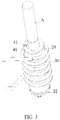
FIG. 3 is a perspective schematic view of a heating mechanism inFIG. 2 from a perspective. -
FIG. 4 is a schematic view illustrating the cross-sectional structure of the heating mechanism inFIG. 3 . -
FIG. 5 is an exploded schematic view of parts of the heating mechanism inFIG. 3 before being assembled. -
FIG. 6 is an exploded schematic view of a susceptor inFIG. 5 from another perspective. -
FIG. 7 is a schematic structural diagram of a susceptor provided according to another embodiment. -
FIG. 8 is a schematic view of a heating mechanism provided according to yet another embodiment. -
FIG. 9 is a schematic view illustrating the cross-sectional structure of the heating structure inFIG. 8 . -
FIG. 10 is a schematic structural diagram of a heater provided according to a further embodiment. - In order to facilitate the understanding of the present application, the present application will be described in more detail below with reference to attached drawings and detailed description.
- One embodiment of the present application provides an aerosol generating device for heating instead of burning a smokable material, such as cigarettes, so as to volatilize or release at least one component of the smokable material to form aerosol for inhalation.
- Reference may be made to
FIG. 1 to FIG. 2 for the structure of the aerosol generating device provided according to an embodiment of the present application. The overall shape of the device is configured generally in the shape of a flat cylinder, and the external components of the aerosol generating device comprise: ahousing 10, which is hollow inside so as to form an assembly space for accommodating necessary functional components such as infrared radiation or the like; anupper cover 11 located at the upper end of thehousing 10 in the length direction; on the one hand, theupper cover 11 may cover the upper end of thehousing 10 so that the appearance of the aerosol generating device is complete and beautiful; and on the other hand, theupper cover 11 is detachable from the upper end of thehousing 10, thereby facilitating the installation, detachment and replacement of various functional components in thehousing 10. - As can be further seen from
FIG. 1 and FIG. 2 , theupper cover 11 has anopening 12 through which the smokable material A may be at least partially received in thehousing 10 along the length direction of thehousing 10 to be heated, or the smokable material A may be removed from thehousing 10 through the opening 12. - The
housing 10 is further provided with aswitch button 13 on one side in the width direction, and a user may manually actuate theswitch button 13 to control the start or stop of the aerosol generating device. - Further referring to
FIG. 2 , thehousing 10 is provided therein with: abattery cell 14 for power supply; acontrol circuit board 15 with an integrated circuit for controlling the operation of the aerosol generating device; acharging interface 16 for charging thebattery cell 14, such as a USB type-C interface or a Pin interface or the like, which is capable of charging thebattery cell 14 after being connected to an external power supply or adapter. - Further referring to the embodiment shown in
FIG. 2 to FIG. 5 , in order to heat the smokable material A, thehousing 10 is provided therein with a heating mechanism, and reference may be made toFIG. 3 for the form and structure of the heating mechanism after being assembled. Specifically, the heating mechanism comprises: atubular support 20, at least a part of the tubular hollow space of thetubular support 20 forming acavity 21 for receiving the smokable material A; a magnetic field generator being configured to generate a varying magnetic field, wherein the magnetic field generator is aninduction coil 30 wound outside thetubular support 20 along the axial direction of thetubular support 20 and is configured to generate the varying magnetic field when alternating current is supplied; as can be seen fromFIG. 5 , theinduction coil 30 has a firstconductive connection portion 31 and a secondconductive connection portion 32 which may be subsequently connected with thecontrol circuit board 15 to supply alternating current to theinduction coil 30; aheater 60 in the shape of a pin or blade, extending at least partially along the axial direction of thecavity 21, and being capable of being inserted into the smokable material A as shown inFIG. 4 . - To further facilitate the installation and fixation of the heating mechanism in the
housing 10, the heating mechanism further comprises: anupper support 40 arranged at the upper end of thetubular support 20, wherein theupper support 40 is in an annular shape coaxial with thetubular support 20, and is provided thereon with afixing structure 41 for connecting and fixing thehousing 10, thereby fixing and holding the upper end of the heating mechanism in thehousing 10. As can be seen fromFIG. 2 andFIG. 4 , thefixing structure 41 is a plurality of clamping protrusions, and correspondingly, thehousing 10 is provided therein with grooves adapted to the clamping protrusions so that the upper end of the heating mechanism is fixed through engagement of the clamping protrusions and the grooves. - Of course, the smokable material A may pass through the central hole of the
upper support 40 to be received in or removed from thecavity 21. - Further referring to
FIG. 4 andFIG. 5 , afixing seat 50 is provided in thetubular support 20 near the lower end, and thefixing seat 50 is configured to form a portion with reduced inner diameter of thecavity 21 in thetubular support 20 so that, on the one hand, the smokable material A may abut against thefixing seat 50 to stop the movement thereof. On the other hand, as shown inFIG. 4 , thefixing seat 50 is penetrated by theheater 60 and theheater 60 abuts against thefixing seat 50, so that theheater 60 can be stably installed or kept in thetubular support 20. - Specifically, referring to
FIG. 5 , thefixing seat 50 has acentral hole 51 penetrating in the axial direction, and thecentral hole 51 is a mounting hole through which theheater 60 penetrates. - Further speaking, in a preferred embodiment shown in
FIG. 4 andFIG. 5 , the lower end of thetubular support 20 is further provided with alower end cover 22, and thelower end cover 22 is configured to cover the lower end of thetubular support 20 so that thefixing seat 50 and theheater 60 are stably installed in thetubular support 20. - In a preferred embodiment, the
tubular support 20, thefixing seat 50 and thelower end cover 22 can all be made of high-temperature resistant organic polymer materials, such as PEEK, polycarbonate, polytetrafluoroethylene or the like, or inorganic ceramic materials with good temperature resistance, such as zirconia ceramics. - In the embodiment of the present application, the
heater 60 is aheater 60 which heats the smokable material A either in an electromagnetic inductive manner or in an infrared radiation manner. Specifically, further referring toFIG. 6 , in a preferred embodiment, the shape and structure of theheater 60 comprise: abase 61 made of rigid infrared-permeable quartz, glass or ceramic materials, and configured in the shape of a pin so as to be inserted into the smokable material A; of course, in order to facilitate the installation and fixing of theheater 60, thebase 61 is provided thereon with abase portion 62 for abutting against and fixing with thefixing seat 50. Thebase 61 is provided therein with ahollow space 63 for receiving aheating element 64, and theheating element 64 is encapsulated or contained in thebase 61 to emit heat and radiate infrared rays. - Specifically, the
heating element 64 comprises a susceptor portion, which is an elongated bar-shaped or rod-shaped susceptor 641 in this embodiment. The susceptor portion is made of a metal material with appropriate magnetic permeability that is inductively coupled with an alternating magnetic field, and it may be penetrated by a varying magnetic field to generate heat. The heat generated sequentially passes through theinfrared emission coating 642 and the base 61 outward in the radial direction, and then is transferred to the smokable material A so that the smokable material A may be heated by heat conduction. Theheating element 64 further comprises a thermally inducedinfrared emission coating 642 formed on thesusceptor 641 or a thermally induced infrared emissionthin film 642 wound on thesusceptor 641. Theinfrared emission coating 642 of theheating element 64 may be excited while receiving the heat from thesusceptor 641, and then radiate far infrared rays with heating effect, such as far infrared rays of 3 µm to 15 µm. When the wavelength of infrared rays matches the absorption wavelength of volatile components of the smokable material A, the energy of infrared rays is easily absorbed by the smokable material so that the smokable material A is heated. - The
susceptor 641 may be made of grade 430 stainless steel (SS430), grade 420 stainless steel (SS420), and alloy materials containing iron and nickel (such as J85/J66 permalloy). It has excellent magnetic permeability, and it can be rapidly heated up under the alternating magnetic field. - The
infrared emission coating 642 is made of a thermally induced infrared emission material. Specifically, theinfrared emission coating 642 includes coatings made of ceramic based materials (e.g., zirconium), or Fe-Mn-Cu based materials and tungsten based materials. - In a preferred embodiment, the
infrared emission coating 642 comprises, but not limited to, the following materials: carbon materials (amorphous carbon film, DLC film, graphene, carbon nanotubes, etc.), oxides (Fe2O3 ,Al2O3 ,Cr2O3 ,In2O3 ,La2O3 ,Co2O3 , Ni2O3 , Sb2O3 , Sb2O5 , TiO2 , ZrO2 , MnO2 , CeO2 , CuO , ZnO , MgO , CaO , MoO3, etc.), carbides (such as SiC, etc.), nitrides (such as TiN, CrN, AIN, Si3N4, etc.) or a combination of two or more of the above materials. Theinfrared emission coating 642 will radiate the far infrared rays with heating effect described above when it is heated to a proper temperature by thesusceptor 641. The thickness of theinfrared emission coating 642 may preferably be controlled to range from 30 µm to 50 µm. Theinfrared emission coating 642 may be formed on the surface ofsusceptor 641 by spraying the above materials on the outer surface ofsusceptor 641 by atmospheric plasma spraying and then curing the materials. - During the use of the
heater 60 described above, on the one hand, thesusceptor 641 generates heat by inductive heating so that the smokable material A is directly heated by heat conduction; and on the other hand, the infrared radiation is excited by the heat of thesusceptor 641, thereby assisting in the heating of the smokable material A, and improving the utilization efficiency of heat. - Furthermore, as can be further seen from the above embodiment, when the
heater 60 is inserted into the smokable material A for heating, theinfrared emission coating 642 surrounds the outside of thesusceptor 641, and this can ensure that the infrared rays emitted by theinfrared emission coating 642 are not blocked and then smoothly radiated to the smokable material A. - Moreover, in the preferred embodiment shown in
FIG. 6 above, the length of thesusceptor 641 extending along the axial direction of theheater 60 is larger than the length of theinfrared emission coating 642, so that thesusceptor 641 can be utilized by theinfrared emission coating 642 to the maximum extent in the heat transmission path or direction, thereby exciting infrared light. - Furthermore, in yet another modified embodiment of the
heater 60a shown inFIG. 7 , theheater 60a comprises a susceptor portion and aninfrared emission coating 62a formed on the outer surface of the susceptor portion. In this embodiment, the susceptor portion is a pin or blade-shapedinduction heating portion 61a. During use, theinduction heating portion 61a is penetrated by the varying magnetic field to generate heat, and at the same time, the thermally inducedinfrared emission coating 62a is heated up and excited to radiate infrared rays. When thesusceptor 60a is inserted into the smokable material A, on the one hand, it may transfer heat to the smokable material A by contact conduction, and on the other hand, it can radiate infrared rays to heat the smokable material A. - Of course, in a more preferred embodiment, an infrared-permeable protective layer (not shown in the figure) such as a layer of glass may be added or formed outside the
infrared emission coating 62a for theheater 60a shown inFIG. 7 . - In yet another variant embodiment, as shown in
FIG. 8 andFIG. 9 , the heating mechanism comprises atubular heater 60b, and aninduction coil 30b surrounding theheater 60b and inductively coupled with theheater 60a for generating a varying magnetic field; the tubular hollow space of theheater 60b forms acavity 63b for accommodating and heating the smokable material A. - Further referring to
FIG. 9 , theheater 60b comprises: a susceptor portion, which may be penetrated by the varying magnetic field to generate heat as a tubular induction heating portion 61b; and a thermally inducedinfrared emission coating 62b formed on the inner surface of the induction heating portion 61b, wherein theinfrared emission coating 62b may be heated by the induction heating portion 61b to radiate infrared rays to the smokable material A in thecavity 63b. - In yet another optional embodiment, the susceptor portion may be in the form of a coating or a thin film. For example, the structure of the
heater 60c may be as shown inFIG. 10 , and it comprises: atubular base 61c which is hollow inside to form acavity 64c for accommodating and receiving the smokable material A; wherein thetubular base 61c is made of infrared-permeable materials such as quartz, glass or ceramic; aninfrared emission coating 62c formed outside thetubular base 61c; asusceptor heating coating 63c further formed outside theinfrared emission coating 62c; wherein thesusceptor heating coating 63c is made of an inductive metal material that generates heat through induction, and may be penetrated by a varying magnetic field to generate heat so that theinfrared emission coating 62c is heated to radiate infrared rays into thecavity 64c, thereby heating the smokable material A. - In other variant embodiments, the
infrared emission coating 62c described above may also adopt an infrared emission thin film, such as a zinc oxide thin film, a graphene thin film, or an indium oxide thin film doped with rare earth metal, or a composite thin film formed with infrared emitting materials on flexible thin film substrates such as polyimide, ceramic paper, and flexible glass. Moreover, the correspondingsusceptor heating coating 63c may be correspondingly changed into the form of a rigid tube made of magnetically conductive metal or alloy. - As can be further seen from the embodiment shown in
FIG. 7 to FIG. 10 , when the heater is tubular around the smokable material A, the infrared emission portion is located in the induction heating portion and closer to the smokable material A, so that the infrared energy emitted by the infrared emission portion can be radiated into the smokable material A without being blocked or absorbed by the induction heating portion. - It shall be noted that, the specification and attached drawings of the present application show preferred embodiments of the present application. However, the present application is not limited to the embodiments described in this specification. Further speaking, those of ordinary skill in the art can make improvements or variations according to the above description, and all these improvements and variations shall fall within the scope claimed in the appended claims of the present application.
Claims (16)
- An aerosol generating device for heating a smokable material to generate aerosol for inhalation, characterized in that, comprising:a cavity, for receiving a smokable material;a magnetic field generator, being configured to generate a varying magnetic field;a heater, being configured to heat the smokable material received in the cavity; the heater comprising:a susceptor portion, being configured to be penetrated by the varying magnetic field to generate heat, and to heat the smokable material received in the cavity by heat conduction; andan infrared emission portion, being configured to be arranged close to the susceptor portion and being capable of receiving the heat transferred by the susceptor portion, and being configured to radiate infrared rays to the cavity to heat the smokable material when it is heated by the susceptor portion.
- The aerosol generating device according to Claim 1, characterized in that, the susceptor portion and the infrared emission portion are in contact with each other so that the susceptor portion transfers heat to the infrared emission portion through contact conduction.
- The aerosol generating device according to Claim 1, characterized in that, at least a part of the axial extension length of the susceptor portion along the cavity coincides with the extension length of the infrared emission portion along the cavity.
- The aerosol generating device according to any of Claims 1 to 3, characterized in that, the heater is configured in the shape of a pin or blade extending at least partially along the axial direction of the cavity.
- The aerosol generating device according to Claim 4, characterized in that, the infrared emission portion is configured to be located outside the susceptor portion along the radial direction of the heater.
- The aerosol generating device according to Claim 4, characterized in that, the heater comprises:a base, being configured in the shape of a pin extending at least partially along the axial direction of the cavity;the base is provided therein with a hollow space extending along the axial direction of the base, and the susceptor portion and the infrared emission portion are accommodated in the hollow space.
- The aerosol generating device according to Claim 6, characterized in that, the susceptor portion extends along the axial direction of the hollow space;
the infrared emission portion is an infrared emission coating formed on the surface of the susceptor portion or an infrared emission thin film wound on the surface of the susceptor portion. - The aerosol generating device according to Claim 4, characterized in that, the susceptor portion is configured in the shape of a pin or blade extending at least partially along the axial direction of the cavity;
the infrared emission portion is a coating formed on the surface of the susceptor portion. - The aerosol generating device according to Claim 8, characterized in that, the heater further comprises a protective layer formed on the surface of the infrared emission portion.
- The aerosol generating device according to any of Claims 1 to 3, characterized in that, the heater is configured in a tubular shape extending along the axial direction of the cavity and surrounding the cavity.
- The aerosol generating device according to Claim 10, characterized in that, the infrared emission portion is configured to be closer to the cavity than the susceptor portion.
- The aerosol generating device according to Claim 10, characterized in that, the susceptor portion is configured in a tubular shape extending along the axial direction of the cavity and surrounding the cavity;
the infrared emission portion is an infrared emission coating formed on the inner surface of the susceptor portion. - The aerosol generating device according to Claim 10, characterized in that, the heater comprises:a base, being configured in a tubular shape extending in the axial direction of the cavity and surrounding the cavity;the infrared emission portion and the susceptor portion are sequentially arranged outward along the radial direction of the base.
- The aerosol generating device according to Claim 13, characterized in that, the infrared emission portion is an infrared emission coating formed on the outer surface of the base or an infrared emission thin film wound on the outer surface of the base.
- The aerosol generating device according to Claim 14, characterized in that, the susceptor portion is a susceptor coating formed on the infrared emission portion; or the susceptor portion is configured as a rigid tube abutting against the infrared emission portion.
- A heater for an aerosol generating device, characterized in that, comprising:a susceptor portion, being configured to be penetrated by a varying magnetic field to generate heat, and to heat a smokable material by heat conduction; andan infrared emission portion, being configured to be arranged close to the susceptor portion and being capable of receiving the heat of the susceptor portion, and being configured to radiate infrared rays to heat the smokable material when it is heated by the susceptor portion.
Applications Claiming Priority (2)
| Application Number | Priority Date | Filing Date | Title |
|---|---|---|---|
| CN202020057718.5U CN211910548U (en) | 2020-01-13 | 2020-01-13 | Aerosol generator and heater |
| PCT/CN2021/071323 WO2021143689A1 (en) | 2020-01-13 | 2021-01-12 | Aerosol generating device and heater |
Publications (3)
| Publication Number | Publication Date |
|---|---|
| EP4091478A1 true EP4091478A1 (en) | 2022-11-23 |
| EP4091478A4 EP4091478A4 (en) | 2023-09-13 |
| EP4091478B1 EP4091478B1 (en) | 2026-03-04 |
Family
ID=73331350
Family Applications (1)
| Application Number | Title | Priority Date | Filing Date |
|---|---|---|---|
| EP21741578.5A Active EP4091478B1 (en) | 2020-01-13 | 2021-01-12 | Aerosol generating device and heater |
Country Status (6)
| Country | Link |
|---|---|
| US (1) | US20230044176A1 (en) |
| EP (1) | EP4091478B1 (en) |
| JP (1) | JP2023509183A (en) |
| KR (1) | KR102797692B1 (en) |
| CN (1) | CN211910548U (en) |
| WO (1) | WO2021143689A1 (en) |
Cited By (1)
| Publication number | Priority date | Publication date | Assignee | Title |
|---|---|---|---|---|
| WO2025083129A1 (en) | 2023-10-19 | 2025-04-24 | Jt International Sa | Heating element with coating of an aerosol-generating device |
Families Citing this family (13)
| Publication number | Priority date | Publication date | Assignee | Title |
|---|---|---|---|---|
| CN211910548U (en) * | 2020-01-13 | 2020-11-13 | 深圳市合元科技有限公司 | Aerosol generator and heater |
| CN113115995B (en) * | 2020-01-13 | 2025-04-22 | 上海合元深蓝科技有限公司 | Aerosol generating device and heater |
| CN112369715A (en) * | 2020-06-12 | 2021-02-19 | 湖北中烟工业有限责任公司 | Heating assembly for smoking substrate |
| WO2021260155A1 (en) * | 2020-06-26 | 2021-12-30 | Nicoventures Trading Limited | Apparatus for heating aerosolisable material |
| CN112674397B (en) * | 2020-12-30 | 2025-05-06 | 深圳市云熙智能有限公司 | Heating element components and low-temperature smoking utensils |
| CN215347059U (en) * | 2021-04-15 | 2021-12-31 | 深圳市合元科技有限公司 | Aerosol generating device and infrared heater |
| KR102542026B1 (en) * | 2021-06-23 | 2023-06-12 | 주식회사 케이티앤지 | Device for generating aerosol |
| CN216147266U (en) * | 2021-07-22 | 2022-04-01 | 深圳麦克韦尔科技有限公司 | Heating device and electronic atomization device |
| KR102713762B1 (en) * | 2021-10-21 | 2024-10-04 | 주식회사 케이티앤지 | Device for generating aerosol and manufacturing method with the same |
| CN118251143A (en) * | 2021-11-17 | 2024-06-25 | 日本烟草产业株式会社 | Aerosol generating device |
| KR102713766B1 (en) * | 2022-01-19 | 2024-10-07 | 주식회사 케이티앤지 | Device for generating aerosol |
| CN114886165A (en) * | 2022-05-11 | 2022-08-12 | 深圳麦时科技有限公司 | Heating assembly and aerosol generating device |
| CN220044942U (en) * | 2023-05-09 | 2023-11-21 | 思摩尔国际控股有限公司 | An aerosol generating device and its heating component |
Family Cites Families (19)
| Publication number | Priority date | Publication date | Assignee | Title |
|---|---|---|---|---|
| JPH01302679A (en) * | 1988-01-28 | 1989-12-06 | Mitsubishi Electric Corp | Extreme infrared radiation heating device with induction heating coil |
| JPH04174990A (en) * | 1989-08-17 | 1992-06-23 | Terumo Kogyo:Kk | High efficiency infrared-ray radiating ceramic heating element |
| JP4295232B2 (en) * | 2005-03-09 | 2009-07-15 | トーカロ株式会社 | Container for electromagnetic induction heating cooker |
| UA114651C2 (en) * | 2012-12-28 | 2017-07-10 | Філіп Морріс Продактс С.А. | Heating assembly for an aerosol generating system |
| TWI666993B (en) * | 2014-05-21 | 2019-08-01 | Philip Morris Products S. A. | Inductive heating device and system for aerosol generation |
| WO2017207580A1 (en) * | 2016-05-31 | 2017-12-07 | Philip Morris Products S.A. | Aerosol generating article with heat diffuser |
| US12478096B2 (en) * | 2016-06-29 | 2025-11-25 | Nicoventures Trading Limited | Apparatus for heating smokable material |
| CN107637862B (en) * | 2016-07-20 | 2023-11-24 | 贵州中烟工业有限责任公司 | Smoking device |
| CN206422941U (en) * | 2017-02-10 | 2017-08-18 | 沈阳寰博磁电科技有限公司 | A kind of electromagnetism far infrared heater |
| CN207754542U (en) * | 2017-10-30 | 2018-08-24 | 深圳市合元科技有限公司 | The apparatus for aerosol creation of adjustable heating region |
| CN109805447B (en) * | 2017-11-22 | 2023-07-04 | 湖南中烟工业有限责任公司 | Magnetic induction composite suction device |
| CN207927771U (en) * | 2018-01-29 | 2018-10-02 | 湖南中烟工业有限责任公司 | A kind of low temperature cigarette being conveniently replaceable heater |
| WO2019157177A1 (en) * | 2018-02-08 | 2019-08-15 | Loto Labs, Inc. | Container for electronic vaporizer device |
| CN208941044U (en) * | 2018-08-07 | 2019-06-07 | 常州市派腾电子技术服务有限公司 | Atomising device and electronic cigarette |
| KR102342331B1 (en) * | 2018-12-07 | 2021-12-22 | 주식회사 케이티앤지 | heater assembly for heating cigarette and aerosol generating device including thereof |
| CN110613173A (en) * | 2019-10-11 | 2019-12-27 | 云南巴菰生物科技有限公司 | Heating device capable of heating tobacco without burning by adopting infrared radiation |
| WO2021108749A1 (en) * | 2019-11-27 | 2021-06-03 | Loto Labs, Inc. | System, method, and computer program product for determining a characteristic of an induction heating circuit |
| CN211910548U (en) * | 2020-01-13 | 2020-11-13 | 深圳市合元科技有限公司 | Aerosol generator and heater |
| CN112369715A (en) * | 2020-06-12 | 2021-02-19 | 湖北中烟工业有限责任公司 | Heating assembly for smoking substrate |
-
2020
- 2020-01-13 CN CN202020057718.5U patent/CN211910548U/en active Active
-
2021
- 2021-01-12 WO PCT/CN2021/071323 patent/WO2021143689A1/en not_active Ceased
- 2021-01-12 JP JP2022541979A patent/JP2023509183A/en active Pending
- 2021-01-12 KR KR1020227027974A patent/KR102797692B1/en active Active
- 2021-01-12 EP EP21741578.5A patent/EP4091478B1/en active Active
- 2021-01-12 US US17/792,676 patent/US20230044176A1/en active Pending
Cited By (1)
| Publication number | Priority date | Publication date | Assignee | Title |
|---|---|---|---|---|
| WO2025083129A1 (en) | 2023-10-19 | 2025-04-24 | Jt International Sa | Heating element with coating of an aerosol-generating device |
Also Published As
| Publication number | Publication date |
|---|---|
| KR102797692B1 (en) | 2025-04-22 |
| EP4091478B1 (en) | 2026-03-04 |
| KR20220126760A (en) | 2022-09-16 |
| US20230044176A1 (en) | 2023-02-09 |
| JP2023509183A (en) | 2023-03-07 |
| WO2021143689A1 (en) | 2021-07-22 |
| CN211910548U (en) | 2020-11-13 |
| EP4091478A4 (en) | 2023-09-13 |
Similar Documents
| Publication | Publication Date | Title |
|---|---|---|
| EP4091478B1 (en) | Aerosol generating device and heater | |
| EP4147588A1 (en) | Heater and aerosol generation device comprising same | |
| CN212279891U (en) | Heater and smoking set comprising same | |
| KR20230050400A (en) | Aerosol generator and infrared heater | |
| US20230263237A1 (en) | Vapor generation device and infrared emitter | |
| EP4190185A1 (en) | Heater and smoking set comprising heater | |
| US20250275579A1 (en) | Aerosol generating device and heating structure thereof | |
| US20230329342A1 (en) | Vapor generation device | |
| WO2022012678A1 (en) | Heater and smoking set comprising heater | |
| CN113080520A (en) | Heater and smoking set comprising same | |
| US12484622B2 (en) | Aerosol generating device | |
| CN113115995B (en) | Aerosol generating device and heater | |
| CN211910545U (en) | Aerosol generating device and infrared emitter for aerosol generating device | |
| EP4088601A1 (en) | Aerosol generating device | |
| US12349729B2 (en) | Aerosol-generating device and infrared emitter | |
| KR102858625B1 (en) | Aerosol generator and infrared radiator | |
| WO2021143835A1 (en) | Low-temperature smoking set | |
| CN215347055U (en) | Aerosol generating device | |
| CN219982156U (en) | Heating assembly and aerosol-generating device | |
| KR20250121567A (en) | Heater and manufacturing method thereof, aerosol generating device | |
| CN222303127U (en) | Aerosol generating device | |
| CN118303670A (en) | Aerosol generating device and heater for aerosol generating device |
Legal Events
| Date | Code | Title | Description |
|---|---|---|---|
| STAA | Information on the status of an ep patent application or granted ep patent |
Free format text: STATUS: THE INTERNATIONAL PUBLICATION HAS BEEN MADE |
|
| PUAI | Public reference made under article 153(3) epc to a published international application that has entered the european phase |
Free format text: ORIGINAL CODE: 0009012 |
|
| STAA | Information on the status of an ep patent application or granted ep patent |
Free format text: STATUS: REQUEST FOR EXAMINATION WAS MADE |
|
| 17P | Request for examination filed |
Effective date: 20220804 |
|
| AK | Designated contracting states |
Kind code of ref document: A1 Designated state(s): AL AT BE BG CH CY CZ DE DK EE ES FI FR GB GR HR HU IE IS IT LI LT LU LV MC MK MT NL NO PL PT RO RS SE SI SK SM TR |
|
| DAV | Request for validation of the european patent (deleted) | ||
| DAX | Request for extension of the european patent (deleted) | ||
| STAA | Information on the status of an ep patent application or granted ep patent |
Free format text: STATUS: EXAMINATION IS IN PROGRESS |
|
| A4 | Supplementary search report drawn up and despatched |
Effective date: 20230816 |
|
| RIC1 | Information provided on ipc code assigned before grant |
Ipc: A24F 40/20 20200101ALN20230809BHEP Ipc: H05B 6/10 20060101ALI20230809BHEP Ipc: A24F 40/465 20200101ALI20230809BHEP Ipc: A24F 40/40 20200101ALI20230809BHEP Ipc: A24F 40/46 20200101AFI20230809BHEP |
|
| 17Q | First examination report despatched |
Effective date: 20230828 |
|
| GRAP | Despatch of communication of intention to grant a patent |
Free format text: ORIGINAL CODE: EPIDOSNIGR1 |
|
| RIC1 | Information provided on ipc code assigned before grant |
Ipc: A24F 40/46 20200101AFI20250723BHEP Ipc: A24F 40/40 20200101ALI20250723BHEP Ipc: A24F 40/465 20200101ALI20250723BHEP Ipc: H05B 6/10 20060101ALI20250723BHEP Ipc: A24F 40/20 20200101ALN20250723BHEP |
|
| STAA | Information on the status of an ep patent application or granted ep patent |
Free format text: STATUS: GRANT OF PATENT IS INTENDED |
|
| RIC1 | Information provided on ipc code assigned before grant |
Ipc: A24F 40/46 20200101AFI20250807BHEP Ipc: A24F 40/40 20200101ALI20250807BHEP Ipc: A24F 40/465 20200101ALI20250807BHEP Ipc: H05B 6/10 20060101ALI20250807BHEP Ipc: A24F 40/20 20200101ALN20250807BHEP |
|
| INTG | Intention to grant announced |
Effective date: 20250828 |
|
| GRAS | Grant fee paid |
Free format text: ORIGINAL CODE: EPIDOSNIGR3 |
|
| GRAA | (expected) grant |
Free format text: ORIGINAL CODE: 0009210 |
|
| STAA | Information on the status of an ep patent application or granted ep patent |
Free format text: STATUS: THE PATENT HAS BEEN GRANTED |
|
| AK | Designated contracting states |
Kind code of ref document: B1 Designated state(s): AL AT BE BG CH CY CZ DE DK EE ES FI FR GB GR HR HU IE IS IT LI LT LU LV MC MK MT NL NO PL PT RO RS SE SI SK SM TR |
|
| REG | Reference to a national code |
Ref country code: CH Ref legal event code: F10 Free format text: ST27 STATUS EVENT CODE: U-0-0-F10-F00 (AS PROVIDED BY THE NATIONAL OFFICE) Effective date: 20260304 Ref country code: GB Ref legal event code: FG4D |
|
| REG | Reference to a national code |
Ref country code: DE Ref legal event code: R096 Ref document number: 602021049240 Country of ref document: DE |
|
| REG | Reference to a national code |
Ref country code: IE Ref legal event code: FG4D |