EP4091476A1 - Heating assembly and low-temperature smoking set - Google Patents
Heating assembly and low-temperature smoking set Download PDFInfo
- Publication number
- EP4091476A1 EP4091476A1 EP21741411.9A EP21741411A EP4091476A1 EP 4091476 A1 EP4091476 A1 EP 4091476A1 EP 21741411 A EP21741411 A EP 21741411A EP 4091476 A1 EP4091476 A1 EP 4091476A1
- Authority
- EP
- European Patent Office
- Prior art keywords
- base
- electrode
- heating assembly
- infrared radiation
- cigarette
- Prior art date
- Legal status (The legal status is an assumption and is not a legal conclusion. Google has not performed a legal analysis and makes no representation as to the accuracy of the status listed.)
- Granted
Links
Images


Classifications
-
- A—HUMAN NECESSITIES
- A24—TOBACCO; CIGARS; CIGARETTES; SIMULATED SMOKING DEVICES; SMOKERS' REQUISITES
- A24F—SMOKERS' REQUISITES; MATCH BOXES; SIMULATED SMOKING DEVICES
- A24F40/00—Electrically operated smoking devices; Component parts thereof; Manufacture thereof; Maintenance or testing thereof; Charging means specially adapted therefor
- A24F40/40—Constructional details, e.g. connection of cartridges and battery parts
- A24F40/46—Shape or structure of electric heating means
- A24F40/465—Shape or structure of electric heating means specially adapted for induction heating
-
- A—HUMAN NECESSITIES
- A24—TOBACCO; CIGARS; CIGARETTES; SIMULATED SMOKING DEVICES; SMOKERS' REQUISITES
- A24F—SMOKERS' REQUISITES; MATCH BOXES; SIMULATED SMOKING DEVICES
- A24F40/00—Electrically operated smoking devices; Component parts thereof; Manufacture thereof; Maintenance or testing thereof; Charging means specially adapted therefor
- A24F40/40—Constructional details, e.g. connection of cartridges and battery parts
- A24F40/46—Shape or structure of electric heating means
-
- A—HUMAN NECESSITIES
- A24—TOBACCO; CIGARS; CIGARETTES; SIMULATED SMOKING DEVICES; SMOKERS' REQUISITES
- A24F—SMOKERS' REQUISITES; MATCH BOXES; SIMULATED SMOKING DEVICES
- A24F40/00—Electrically operated smoking devices; Component parts thereof; Manufacture thereof; Maintenance or testing thereof; Charging means specially adapted therefor
- A24F40/20—Devices using solid inhalable precursors
Definitions
- the present invention relates to the technical field of low-temperature smoking sets, and in particular, relates to a heating assembly and a low-temperature smoking set.
- a cigarette accommodating cavity is arranged in the smoking set, and the heating body is either located in the cigarette accommodating cavity (for the central heating type) in which the heating body needs to be inserted into the cigarette when the cigarette is to be heated, or located around the cigarette accommodating cavity (for the circumferential heating type) in which the heating body is located around the cigarette (i.e., the cigarette is placed inside the heating body) when the cigarette is to be heated.
- the heating body is supplied with power to generate heat so as to heat the cigarette in the cigarette accommodating cavity.
- the low-temperature smoking sets of the circumferential heating type which are currently available usually comprise a heating tube, and the peripheral surface of the heating tube is provided with a layer of electro-heating coating film and electrodes sleeved on the coating film.
- the electrodes are in interference fit with the coating film and are used for conveying electric energy to the coating film.
- the coating film is likely to be scraped off so that the electrical connection is unreliable, and the electrode is likely to fall off.
- the present utility model provides a heating assembly with reliable electrical connection of electrodes and a low-temperature smoking set.
- the present utility model provides a heating assembly for baking a cigarette, wherein the heating assembly comprises a heating body and a cavity for containing at least a part of the cigarette, the heating body comprises a base, an infrared radiation layer and electrodes, the base comprises a surface, the infrared radiation layer is arranged on the surface for generating infrared radiation to heat at least a part of the cigarette located in the cavity; at least a part of the electrode is recessed from the surface and buried in the base, so that the electrode and the base are formed into an integral structure, and the electrode is electrically connected with the infrared radiation layer.
- the infrared radiation layer covers at least a part of the electrode so as to be electrically connected with the electrode.
- At least a part of the electrode has a side that is substantially aligned with the surface of the base.
- the electrode comprises an electrical connection part for providing conductive connection between the heating assembly and other members, and the electrical connection part protrudes from the surface relative to the base.
- the base is tubular with the cavity formed inside, and the outer surface of the base is configured as the surface, and the electrical connection part forms a flange around the outer surface of the base.
- the electrode has an opening to form a non-closed ring shape.
- the base is tubular with the cavity formed inside, and the inner surface of the base is configured as the surface, and at least a part of the electrode penetrates through the inner surface of the base and extends to the outer surface of the base.
- the electrode comprises an annular body and a tab, and the body is recessed from the inner surface of the base and buried in the base; the tab is connected with the body, penetrates through the outer surface of the base and protrudes from the outer surface.
- the number of the electrodes is two, and the two electrodes are correspondingly located at opposite ends of the base.
- the present utility model further provides a low-temperature smoking set which comprises a housing assembly and a heating assembly, the heating assembly is accommodated in the housing assembly, wherein the heating assembly is the heating assembly according to any item of the first aspect described above.
- the present utility model has the following beneficial effects: according to the present utility model, the base, the infrared radiation layer and the electrodes cooperate with each other, the base comprises a surface, the infrared radiation layer is arranged on the surface, and at least a part of the electrode is recessed from the surface and buried in the base so that the electrode and the base are form into an integral structure; during production, first the electrode and the base are integrally formed, and then the infrared radiation layer is formed on the base, thereby well preventing the infrared radiation layer from being scraped off and preventing the electrodes from falling off, and providing reliable electrical connection of the electrodes.
- the present utility model provides a low-temperature smoking set, which comprises a housing assembly 1, a bracket 2, a battery 3 and a heating assembly 4, wherein the housing assembly 1 comprises a casing 11 and an end cover 12, and a key switch 5 electrically connected with the battery 3 and the heating assembly 4 is installed on the casing 11.
- the key switch 5 is configured to control the battery 3 to supply power to the heating assembly 4 so as to bake the cigarette 10.
- the end cover 12 covers one end face of the casing 11, and the end cover 12 is opened with an insertion hole 121 for the cigarette 10 to be inserted therein.
- the bracket 2 is accommodated in and connected with the casing 11, and the battery 3 is located in the casing 11 and mounted on the bracket 2.
- both the end cover 12 and the bracket 2 are detachably connected with the casing 11.
- the bracket 2 and the casing 11 are an integrally formed structure. Therefore, the structures of the housing assembly 1 and the bracket 2 are not particularly limited herein, as long as the battery 3 and the heating assembly 4 can be mounted.
- the heating assembly 4 is configured to heat the cigarette, and it has a cigarette accommodating cavity P1 for the cigarette to be inserted therein.
- the cavity wall of the cigarette accommodating cavity P1 is provided with a plurality of elastic convex parts P2 arranged at intervals.
- the elastic convex parts P2 are sheet-shaped and extend along the transverse direction of the cigarette accommodating cavity PI, and the elastic convex parts P2 are provided with arc-shaped abutting surfaces P3 for abutting against the cigarette 10.
- the number of the elastic convex parts P2 is not particularly limited herein as well as the number is at least two.
- the elastic convex part P2 is arranged at the orifice of the insertion hole 121, and the insertion hole 121 serves as the mouth of the cigarette accommodating cavity PI; that is, the elastic convex part P2 is located at the mouth of the cigarette accommodating cavity P1.
- the elastic convex part P2 may be located at or below the middle of the cigarette accommodating cavity PI, so the position thereof is not particularly limited herein.
- the heating assembly 4 comprises a heating body 41, a first fixing seat 42, a second fixing seat 43, a fixing cap 44, a heat insulation tube 45 and an electrode 46.
- the heating body 41 is configured to heat the cigarette 10, and the heating body 41 comprises a base 411 and an infrared radiation layer 412.
- the base 411 is a tubular structure and is used for accommodating the cigarette 10.
- the base 411 has opposite first and second ends, and a surface to which the infrared radiation layer 412 is attached.
- the base 411 extends in the longitudinal direction between the first and second ends, and a cavity 413 for accommodating the cigarette 10 is formed therein.
- the peripheral surface of the base 411 is the surface to which the infrared radiation layer 412 is attached, i.e., the infrared radiation layer 412 is disposed on the surface.
- the base 411 may be in cylindrical, prismatic or other columnar shapes.
- the base 411 is preferably cylindrical, then the cavity 413 is a cylindrical hole penetrating through the middle of the base 411, and the inner diameter of the hole is slightly larger than the outer diameter of the cigarette, so that it is convenient to place the cigarette in the cavity 413 to be heated.
- the base 411 may be made of high-temperature resistant and transparent materials such as quartz glass, ceramic or mica, or other materials with higher infrared transmittance, such as high-temperature resistant materials with infrared transmittance of more than 95%, and this is not particularly limited herein.
- the infrared radiation layer 412 is electrically connected with the battery 3 through the electrode 46 and a wire electrically connected with the electrode 46.
- the infrared radiation layer 412 is configured to generate infrared radiation to heat at least a part of the cigarette 10 located in the cavity 413.
- the infrared radiation layer 412 receives electric power to generate heat so as to generate infrared rays, and at least transmits the energy of the infrared rays to the cigarette 10 by radiation.
- the infrared radiation layer 412 may be a coating coated on the outer surface of the base 411 or a coating coated on the inner surface of the base 411.
- the infrared radiation layer 412 is disposed on the outer surface of the base 411.
- the infrared radiation layer 412 can generate heat energy when it is powered on so as to generate infrared rays with a certain wavelength, for example, far infrared rays of 8 ⁇ m to 15 ⁇ m.
- a certain wavelength for example, far infrared rays of 8 ⁇ m to 15 ⁇ m.
- the wavelength of the infrared rays matches the absorption wavelength of the cigarette, the energy of the infrared rays is easily absorbed by the cigarette.
- the wavelength of the infrared rays is not limited, but the infrared rays may be infrared rays of 0.75 ⁇ m to 1000 ⁇ m, and preferably far infrared rays of 1.5 ⁇ m to 400 ⁇ m.
- the infrared radiation layer 412 is preferably prepared by coating far infrared electrothermal ink, ceramic powder and inorganic adhesive, which are fully and uniformly stirred, on the outer surface of the base 411, and then drying and curing the resultant for a certain time.
- the thickness of the infrared radiation layer 412 is 30 ⁇ m to 50 ⁇ m.
- the infrared radiation layer 412 may also be prepared by coating tin tetrachloride, tin oxide, antimony trichloride, titanium tetrachloride and anhydrous copper sulfate, which are mixed at a certain proportion and stirred, on the outer surface of the base 411.
- the infrared radiation layer 412 is one of a silicon carbide ceramic layer, a carbon fiber composite layer, a zirconium titanium oxide ceramic layer, a zirconium titanium nitride ceramic layer, a zirconium titanium boride ceramic layer, a zirconium titanium carbide ceramic layer, an iron oxide ceramic layer, an iron nitride ceramic layer, an iron boride ceramic layer, an iron carbide ceramic layer, a rare earth oxide ceramic layer, a rare earth nitride ceramic layer, a rare earth boride ceramic layer, a rare earth carbide ceramic layer, a nickel cobalt oxide ceramic layer, a nickel cobalt nitride ceramic layer, a nickel cobalt boride ceramic layer, a nickel cobalt carbide ceramic layer or a high-silica zeolite ceramic layer.
- the infrared radiation layer 412 may also be an existing coating of other materials.
- the infrared radiation layer 412 is coated on the inner surface of the base 411, and the heating assembly 4 further comprises a protective layer coated on the infrared radiation layer 412 and/or a protective structure provided on the infrared radiation layer 412.
- the protective layer may be one or a combination of a polytetrafluoroethylene layer and a glaze layer, or a protective layer made of other high-temperature resistant materials.
- the protective structure may be an assembly or component that separates the cigarette from the infrared radiation layer 412, and there may be a gap between the protective structure and the infrared radiation layer 412 or the cigarette.
- the protective layer and/or the protective structure can avoid the abrasion of the infrared radiation layer 412 caused by for example the movement of the cigarette into and out of the cavity 413.
- the infrared radiation layer 412 may also be a thin film with infrared radiation material that is attached on the surface of the base 111.
- the infrared radiation layer 412 may generate infrared rays when the infrared radiation layer 412 itself is powered on, or the infrared radiation layer 412 may generate infrared rays when it is excited by heat conduction from other heating devices, and this is not particularly limited herein.
- the first fixing seat 42 is sleeved on the first end of the heating body 41 and connected with the heating body 41 and the housing assembly 1.
- the fixing cap 44 is detachably sleeved on the first fixing seat 42, so that it is convenient for replacement and maintenance.
- the fixing cap 44 comprises a collar part 441, a connection part 442 and elastic convex parts P2, wherein the collar part 441 is sleeved on the first fixing seat 42, and one end of the collar part 441 extends toward the axis of the collar part 441 to form a plurality of elastic convex parts P2, which are arranged at equal intervals.
- the elastic convex parts P2 are centrosymmetric about the center line of the cigarette accommodating cavity PI, so that when the cigarette 10 is clamped, the stress imposed on the cigarette 10 is uniform.
- the heating body 41, the first fixing seat 42 and the fixing cap 44 jointly define and form the cigarette accommodating cavity P1.
- connection part 442 is connected to one of the elastic convex parts P2, and the other end of the connection part 442 is connected with another elastic convex part P2. That is, a connection part 442 is connected between adjacent elastic convex parts P2, and thus it is easier for the elastic convex parts P2 to reset when the cigarette is pulled out.
- the collar part 441 is connected with the connection part 442, and the connection part 442 and the elastic convex parts P2 are located in the same plane, so that the resetting ability of the elastic convex parts P2 can be improved, and the service life can be prolonged.
- the fixing cap 44 is made of silica gel material and it is an integrally formed structure, so it is convenient for manufacturing, and moreover, it is less likely to scratch the cigarette 10 when the cigarette is inserted.
- the material of the fixing cap 44 is not particularly limited herein. In some embodiments, it may be unnecessary to provide the first fixing seat 42 or/and the fixing cap 44.
- the cavity wall of the cigarette accommodating cavity P1 is provided with at least two elastic convex parts P2 which are arranged at intervals, the elastic convex parts P2 are sheet-shaped and extend along the transverse direction of the cigarette accommodating cavity PI, and the elastic convex parts P2 are provided with arc-shaped abutting surfaces P3 for abutting against the cigarette. Therefore, when a cigarette with a large diameter is inserted into the cigarette accommodating cavity PI, the elastic convex parts P2 are elastically deformed so that the cigarette can be inserted into the cigarette accommodating cavity P1. That is, self-adaptive adjustment according to the cigarette diameter is realized to adapt to cigarettes with different diameters. In addition, because the elastic convex parts P2 are sheet-shaped, it may well block heat dissipation and ensure the baking efficiency for the cigarette.
- the peripheral surface of the first fixing seat 42 is provided with a plurality of convex ribs 421 which extend along the length direction of the first fixing seat 42.
- a wire groove 431 is provided on the peripheral surface of the second fixing seat 43, and the wire groove 431 extends along the length direction of the second fixing seat 43 and is used for the wires connected between the battery 3 and the electrode 46 to pass through.
- a first end of the heating body 41 is inserted into the first fixing seat 42, a second end of the heating body 41 is inserted into the second fixing seat 43, and the second fixing seat 43 is mounted on the bracket 2 so that the heating body 41 can be reliably fixed.
- a first end of the heat insulation tube 45 is sleeved on the convex rib 421 of the peripheral surface of the first fixing seat 42, a second end of the heat insulation tube 45 is sleeved on the peripheral surface of the second fixing seat 43, and a gap is formed between the heat insulation tube 45 and the heating body 41.
- the convex ribs 421 With the arrangement of the convex ribs 421, the convex ribs 421 are deformed when the first end of the heat insulation tube 45 is sleeved on the second fixing seat 43, thereby facilitating the assembly.
- the electrode 46 is partially recessed from the surface of the base 411 and buried in the base 411, and forms an integral structure with the base 411.
- the base 411 is made of a ceramic material
- the electrode 46 and the ceramic blank are sintered at high temperature to form an integral structure, and then the infrared radiation layer 412 is coated on the base 411 so that the electrode 46 and the infrared radiation layer 412 are electrically connected. In this way, the problem that the infrared radiation layer 412 is scraped off when the electrode 46 is mounted on the base 411 can be avoided.
- the electrode 46 has an opening 460 to form a non-closed ring shape, so that when the base 411 expands when it is heated, the electrode 46 will not be broken due to the expansion of the base 411.
- the number of the electrodes 46 is two, and the two electrodes 46 are respectively located at opposite ends of the base 411 and are respectively electrically connected with the positive and negative electrodes of the battery 3. Since the electrode 46 is in the non-closed ring shape, the fixation is stable.
- the infrared radiation layer 412 is formed on the peripheral surface of the base 411 and covers a part of the electrode 46. That is, the infrared radiation layer 412 is coated on part of area of the electrode 46 so that reliable electrical connection is achieved between the infrared radiation layer 412 and the electrode 46.
- the infrared radiation layer 412 is tubular, and the diameter of the infrared radiation layer 412 is larger than the diameter of the electrode 46.
- the electrode 46 has a side that is substantially aligned with the surface of the base 411 on which the infrared radiation layer 412 is arranged, so it is easier to coat the infrared radiation layer 412 during production, and the infrared radiation layer 412 covers the electrode 46 conveniently.
- the area of the electrode 46 covered by the infrared radiation layer 412 may be set as required, and this is not particularly limited herein.
- FIG. 8 is a perspective view of a heating body of a low-temperature smoking set provided according to yet another embodiment of the present utility model.
- the base 411 is tubular with the cavity 413 formed inside, and the inner surface of the base 411 is configured as a surface on which the infrared radiation layer 412 is arranged.
- Part of the electrode 46 penetrates through the inner surface of the base 411 and extends to the outer surface of the base 411 so that it is convenient to be connected with wires by welding.
- the electrode 46 comprises an annular body 461 and a tab 462, wherein the body 461 is recessed from the inner surface of the base 411 and buried in the base 411, and the tab 462 is connected with the body 461 and penetrates through the outer surface of the base 411.
- the tab 462 is used for connection with a wire by welding so as to be electrically connected to the battery 3.
- the tab 462 penetrates through the outer surface of the base 41 and protrudes from the outer surface. Therefore, the structure is not particularly limited herein as long as the base 411 and the electrode 46 are an integrally formed structure.
- FIG. 9 is a perspective view of a heating body of a low-temperature smoking set provided according to yet another embodiment of the present utility model.
- the base 411 of this embodiment is tubular with the cavity 413 formed inside, and the outer surface of the base 411 is configured as a surface on which the infrared radiation layer 412 is arranged.
- the electrode 46 of this embodiment comprises a fixing ring 463 and an electrical connection part 464 located on the peripheral surface of the fixing ring 463.
- the fixing ring 463 is recessed from the outer surface of the base 411 and buried in the base 411 so that the electrode 46 and the base 411 are formed into an integral structure, and the electrical connection part 464 protrudes from the surface relative to the base 411.
- the electrical connection part 464 forms a flange around the outer surface of the base 411, and is electrically connected with the wire through the flange so as to be electrically connected with the battery 3. Therefore, the arrangement of the flange facilitates the welding.
- Both ends of the base 411 are provided with the electrodes 46, and the infrared radiation layer 412412 surrounds the outer surface of the base 411 and is located between the electrodes 46.
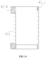
- FIG. 10 is a perspective view of a heating body of a low-temperature smoking set provided according to yet another embodiment of the present utility model.
- the base 411 is tubular with the cavity 413 formed inside, and the inner surface of the base 411 is configured as a surface on which the infrared radiation layer 412 is arranged.
- the electrode 46 of this embodiment comprises a fixing ring 463 and an electrical connection part 464 for providing conductive connection between the heating assembly and other members.
- the fixing ring 463 is recessed from the inner surface of the base 411 and buried in the base 411 so that the electrode 46 and the base 411 are formed into an integral structure.
- the electrical connection part 464 protrudes from the outer surface of the base 411 relative to the base 411, which facilitates the welding. Specifically, the electrical connection part 464 is connected with a wire by welding so as to be electrically connected with the battery 3 through the wire.
- the base 411, the infrared radiation layer 412 and the electrodes 46 cooperate with each other, the base 411 comprises a surface, the infrared radiation layer 412 is arranged on the surface, and at least a part of the electrode 46 is recessed from the surface and buried in the base 411 so that the electrode 46 and the base 411 are formed into an integral structure; during production, first the electrode 46 and the base 411 are integrally formed, and then the infrared radiation layer 412 is formed on the base 411, thereby well preventing the infrared radiation layer 412 from being scraped off and preventing the electrodes 46 from falling off.
Landscapes
- Resistance Heating (AREA)
Abstract
Description
- The present application claims priority to
Chinese Patent Application No. 202020094140.0, filed with the Chinese Patent Office on January 16, 2020 - The present invention relates to the technical field of low-temperature smoking sets, and in particular, relates to a heating assembly and a low-temperature smoking set.
- Traditional cigarettes made of tobacco needs to be ignited by open fire and burned to produce smoke. In the process of high-temperature heating and pyrolysis, tobacco releases thousands of mixed substances harmful to human body, which are composed of volatile substances existing in gas and semi-volatile and non-volatile substances existing in particles, such as carbon monoxide, phenols, aldehydes, nicotine (nicotinamide), cigarette tar or the like. In contrast, low-temperature cigarettes can effectively reduce the generation of harmful substances and thus be healthier.
- Therefore, low-temperature smoking sets came into being. Common low-temperature smoking sets currently available are generally divided into central heating type and circumferential heating type. General structures thereof are as follows: a cigarette accommodating cavity is arranged in the smoking set, and the heating body is either located in the cigarette accommodating cavity (for the central heating type) in which the heating body needs to be inserted into the cigarette when the cigarette is to be heated, or located around the cigarette accommodating cavity (for the circumferential heating type) in which the heating body is located around the cigarette (i.e., the cigarette is placed inside the heating body) when the cigarette is to be heated. During use, the heating body is supplied with power to generate heat so as to heat the cigarette in the cigarette accommodating cavity.
- The low-temperature smoking sets of the circumferential heating type which are currently available usually comprise a heating tube, and the peripheral surface of the heating tube is provided with a layer of electro-heating coating film and electrodes sleeved on the coating film. The electrodes are in interference fit with the coating film and are used for conveying electric energy to the coating film. However, in the process of assembling the electrodes, the coating film is likely to be scraped off so that the electrical connection is unreliable, and the electrode is likely to fall off.
- In order to solve the problems in the prior art, the present utility model provides a heating assembly with reliable electrical connection of electrodes and a low-temperature smoking set.
- In a first aspect, the present utility model provides a heating assembly for baking a cigarette, wherein the heating assembly comprises a heating body and a cavity for containing at least a part of the cigarette, the heating body comprises a base, an infrared radiation layer and electrodes, the base comprises a surface, the infrared radiation layer is arranged on the surface for generating infrared radiation to heat at least a part of the cigarette located in the cavity; at least a part of the electrode is recessed from the surface and buried in the base, so that the electrode and the base are formed into an integral structure, and the electrode is electrically connected with the infrared radiation layer.
- Preferably, the infrared radiation layer covers at least a part of the electrode so as to be electrically connected with the electrode.
- Preferably, at least a part of the electrode has a side that is substantially aligned with the surface of the base.
- Preferably, the electrode comprises an electrical connection part for providing conductive connection between the heating assembly and other members, and the electrical connection part protrudes from the surface relative to the base.
- Preferably, the base is tubular with the cavity formed inside, and the outer surface of the base is configured as the surface, and the electrical connection part forms a flange around the outer surface of the base.
- Preferably, the electrode has an opening to form a non-closed ring shape.
- Preferably, the base is tubular with the cavity formed inside, and the inner surface of the base is configured as the surface, and at least a part of the electrode penetrates through the inner surface of the base and extends to the outer surface of the base.
- Preferably, the electrode comprises an annular body and a tab, and the body is recessed from the inner surface of the base and buried in the base; the tab is connected with the body, penetrates through the outer surface of the base and protrudes from the outer surface.
- Preferably, the number of the electrodes is two, and the two electrodes are correspondingly located at opposite ends of the base.
- In a second aspect, the present utility model further provides a low-temperature smoking set which comprises a housing assembly and a heating assembly, the heating assembly is accommodated in the housing assembly, wherein the heating assembly is the heating assembly according to any item of the first aspect described above.
- The present utility model has the following beneficial effects: according to the present utility model, the base, the infrared radiation layer and the electrodes cooperate with each other, the base comprises a surface, the infrared radiation layer is arranged on the surface, and at least a part of the electrode is recessed from the surface and buried in the base so that the electrode and the base are form into an integral structure; during production, first the electrode and the base are integrally formed, and then the infrared radiation layer is formed on the base, thereby well preventing the infrared radiation layer from being scraped off and preventing the electrodes from falling off, and providing reliable electrical connection of the electrodes.
- One or more embodiments are illustrated by pictures in corresponding attached drawings, and this does not constitute limitation on the embodiments. Elements with the same reference numerals in the attached drawings are shown as similar elements, and the pictures in the attached drawings do not constitute scale limitation unless otherwise stated particularly.
-
FIG. 1 is a perspective view of a low-temperature smoking set provided according to an embodiment of the present utility model. -
FIG. 2 is a perspective view of the low-temperature smoking set shown inFIG. 1 with a cigarette inserted therein. -
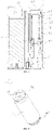
FIG. 3 is a cross-sectional view of the low-temperature smoking set shown inFIG. 1 . -
FIG. 4 is a perspective view of a heating assembly of the low-temperature smoking set shown inFIG. 1 . -
FIG. 5 is an exploded view of the heating assembly of the low-temperature smoking set shown inFIG. 1 . -
FIG. 6 is a perspective view of a fixing cap of the low-temperature smoking set shown inFIG. 1 . -
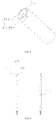
FIG. 7 is a perspective view of an electrode of the low-temperature smoking set shown inFIG. 1 . -
FIG. 8 is a perspective view of a heating body of a low-temperature smoking set provided according to yet another embodiment of the present utility model. -
FIG. 9 is a perspective view of a heating body of a low-temperature smoking set provided according to yet another embodiment of the present utility model. -
FIG. 10 is a perspective view of a heating body of a low-temperature smoking set provided according to yet another embodiment of the present utility model. - In order to facilitate the understanding of the present utility model, the present utility model will be described in more detail below with reference to attached drawings and detailed description.
- Referring to
FIG. 1 to FIG. 7 , the present utility model provides a low-temperature smoking set, which comprises a housing assembly 1, abracket 2, a battery 3 and a heating assembly 4, wherein the housing assembly 1 comprises acasing 11 and anend cover 12, and akey switch 5 electrically connected with the battery 3 and the heating assembly 4 is installed on thecasing 11. Thekey switch 5 is configured to control the battery 3 to supply power to the heating assembly 4 so as to bake thecigarette 10. Theend cover 12 covers one end face of thecasing 11, and theend cover 12 is opened with aninsertion hole 121 for thecigarette 10 to be inserted therein. Thebracket 2 is accommodated in and connected with thecasing 11, and the battery 3 is located in thecasing 11 and mounted on thebracket 2. - In this embodiment, both the
end cover 12 and thebracket 2 are detachably connected with thecasing 11. In a certain embodiment, it may be unnecessary to provide theend cover 12, and thebracket 2 and thecasing 11 are an integrally formed structure. Therefore, the structures of the housing assembly 1 and thebracket 2 are not particularly limited herein, as long as the battery 3 and the heating assembly 4 can be mounted. - The heating assembly 4 is configured to heat the cigarette, and it has a cigarette accommodating cavity P1 for the cigarette to be inserted therein. The cavity wall of the cigarette accommodating cavity P1 is provided with a plurality of elastic convex parts P2 arranged at intervals. The elastic convex parts P2 are sheet-shaped and extend along the transverse direction of the cigarette accommodating cavity PI, and the elastic convex parts P2 are provided with arc-shaped abutting surfaces P3 for abutting against the
cigarette 10. As shall be appreciated, the number of the elastic convex parts P2 is not particularly limited herein as well as the number is at least two. - In one embodiment, the elastic convex part P2 is arranged at the orifice of the
insertion hole 121, and theinsertion hole 121 serves as the mouth of the cigarette accommodating cavity PI; that is, the elastic convex part P2 is located at the mouth of the cigarette accommodating cavity P1. In this way, the problem that the heat of the heating assembly 4 influences the elastic convex part P2 so that deformation occurs easily may be well avoided. Of course, the elastic convex part P2 may be located at or below the middle of the cigarette accommodating cavity PI, so the position thereof is not particularly limited herein. - In this embodiment, the heating assembly 4 comprises a
heating body 41, afirst fixing seat 42, asecond fixing seat 43, afixing cap 44, aheat insulation tube 45 and anelectrode 46. Theheating body 41 is configured to heat thecigarette 10, and theheating body 41 comprises abase 411 and an infrared radiation layer 412. Thebase 411 is a tubular structure and is used for accommodating thecigarette 10. Thebase 411 has opposite first and second ends, and a surface to which the infrared radiation layer 412 is attached. Thebase 411 extends in the longitudinal direction between the first and second ends, and acavity 413 for accommodating thecigarette 10 is formed therein. In this embodiment, the peripheral surface of thebase 411 is the surface to which the infrared radiation layer 412 is attached, i.e., the infrared radiation layer 412 is disposed on the surface. - The
base 411 may be in cylindrical, prismatic or other columnar shapes. Thebase 411 is preferably cylindrical, then thecavity 413 is a cylindrical hole penetrating through the middle of thebase 411, and the inner diameter of the hole is slightly larger than the outer diameter of the cigarette, so that it is convenient to place the cigarette in thecavity 413 to be heated. Thebase 411 may be made of high-temperature resistant and transparent materials such as quartz glass, ceramic or mica, or other materials with higher infrared transmittance, such as high-temperature resistant materials with infrared transmittance of more than 95%, and this is not particularly limited herein. - The infrared radiation layer 412 is electrically connected with the battery 3 through the
electrode 46 and a wire electrically connected with theelectrode 46. The infrared radiation layer 412 is configured to generate infrared radiation to heat at least a part of thecigarette 10 located in thecavity 413. In this embodiment, the infrared radiation layer 412 receives electric power to generate heat so as to generate infrared rays, and at least transmits the energy of the infrared rays to thecigarette 10 by radiation. The infrared radiation layer 412 may be a coating coated on the outer surface of the base 411 or a coating coated on the inner surface of thebase 411. Preferably, the infrared radiation layer 412 is disposed on the outer surface of thebase 411. - The infrared radiation layer 412 can generate heat energy when it is powered on so as to generate infrared rays with a certain wavelength, for example, far infrared rays of 8 µm to 15 µm. When the wavelength of the infrared rays matches the absorption wavelength of the cigarette, the energy of the infrared rays is easily absorbed by the cigarette. In the embodiment of the present application, the wavelength of the infrared rays is not limited, but the infrared rays may be infrared rays of 0.75 µm to 1000 µm, and preferably far infrared rays of 1.5 µm to 400 µm.
- The infrared radiation layer 412 is preferably prepared by coating far infrared electrothermal ink, ceramic powder and inorganic adhesive, which are fully and uniformly stirred, on the outer surface of the
base 411, and then drying and curing the resultant for a certain time. The thickness of the infrared radiation layer 412 is 30 µm to 50 µm. Of course, the infrared radiation layer 412 may also be prepared by coating tin tetrachloride, tin oxide, antimony trichloride, titanium tetrachloride and anhydrous copper sulfate, which are mixed at a certain proportion and stirred, on the outer surface of thebase 411. Alternatively, the infrared radiation layer 412 is one of a silicon carbide ceramic layer, a carbon fiber composite layer, a zirconium titanium oxide ceramic layer, a zirconium titanium nitride ceramic layer, a zirconium titanium boride ceramic layer, a zirconium titanium carbide ceramic layer, an iron oxide ceramic layer, an iron nitride ceramic layer, an iron boride ceramic layer, an iron carbide ceramic layer, a rare earth oxide ceramic layer, a rare earth nitride ceramic layer, a rare earth boride ceramic layer, a rare earth carbide ceramic layer, a nickel cobalt oxide ceramic layer, a nickel cobalt nitride ceramic layer, a nickel cobalt boride ceramic layer, a nickel cobalt carbide ceramic layer or a high-silica zeolite ceramic layer. The infrared radiation layer 412 may also be an existing coating of other materials. - In one embodiment, the infrared radiation layer 412 is coated on the inner surface of the
base 411, and the heating assembly 4 further comprises a protective layer coated on the infrared radiation layer 412 and/or a protective structure provided on the infrared radiation layer 412. The protective layer may be one or a combination of a polytetrafluoroethylene layer and a glaze layer, or a protective layer made of other high-temperature resistant materials. The protective structure may be an assembly or component that separates the cigarette from the infrared radiation layer 412, and there may be a gap between the protective structure and the infrared radiation layer 412 or the cigarette. The protective layer and/or the protective structure can avoid the abrasion of the infrared radiation layer 412 caused by for example the movement of the cigarette into and out of thecavity 413. As shall be appreciated, the infrared radiation layer 412 may also be a thin film with infrared radiation material that is attached on the surface of the base 111. In addition, the infrared radiation layer 412 may generate infrared rays when the infrared radiation layer 412 itself is powered on, or the infrared radiation layer 412 may generate infrared rays when it is excited by heat conduction from other heating devices, and this is not particularly limited herein. - The first fixing
seat 42 is sleeved on the first end of theheating body 41 and connected with theheating body 41 and the housing assembly 1. The fixingcap 44 is detachably sleeved on the first fixingseat 42, so that it is convenient for replacement and maintenance. The fixingcap 44 comprises a collar part 441, aconnection part 442 and elastic convex parts P2, wherein the collar part 441 is sleeved on the first fixingseat 42, and one end of the collar part 441 extends toward the axis of the collar part 441 to form a plurality of elastic convex parts P2, which are arranged at equal intervals. The elastic convex parts P2 are centrosymmetric about the center line of the cigarette accommodating cavity PI, so that when thecigarette 10 is clamped, the stress imposed on thecigarette 10 is uniform. Theheating body 41, the first fixingseat 42 and the fixingcap 44 jointly define and form the cigarette accommodating cavity P1. - One end of the
connection part 442 is connected to one of the elastic convex parts P2, and the other end of theconnection part 442 is connected with another elastic convex part P2. That is, aconnection part 442 is connected between adjacent elastic convex parts P2, and thus it is easier for the elastic convex parts P2 to reset when the cigarette is pulled out. Preferably, the collar part 441 is connected with theconnection part 442, and theconnection part 442 and the elastic convex parts P2 are located in the same plane, so that the resetting ability of the elastic convex parts P2 can be improved, and the service life can be prolonged. In this embodiment, the fixingcap 44 is made of silica gel material and it is an integrally formed structure, so it is convenient for manufacturing, and moreover, it is less likely to scratch thecigarette 10 when the cigarette is inserted. As shall be appreciated, the material of the fixingcap 44 is not particularly limited herein. In some embodiments, it may be unnecessary to provide the first fixingseat 42 or/and the fixingcap 44. - The cavity wall of the cigarette accommodating cavity P1 is provided with at least two elastic convex parts P2 which are arranged at intervals, the elastic convex parts P2 are sheet-shaped and extend along the transverse direction of the cigarette accommodating cavity PI, and the elastic convex parts P2 are provided with arc-shaped abutting surfaces P3 for abutting against the cigarette. Therefore, when a cigarette with a large diameter is inserted into the cigarette accommodating cavity PI, the elastic convex parts P2 are elastically deformed so that the cigarette can be inserted into the cigarette accommodating cavity P1. That is, self-adaptive adjustment according to the cigarette diameter is realized to adapt to cigarettes with different diameters. In addition, because the elastic convex parts P2 are sheet-shaped, it may well block heat dissipation and ensure the baking efficiency for the cigarette.
- The peripheral surface of the first fixing
seat 42 is provided with a plurality ofconvex ribs 421 which extend along the length direction of the first fixingseat 42. Awire groove 431 is provided on the peripheral surface of the second fixingseat 43, and thewire groove 431 extends along the length direction of the second fixingseat 43 and is used for the wires connected between the battery 3 and theelectrode 46 to pass through. A first end of theheating body 41 is inserted into the first fixingseat 42, a second end of theheating body 41 is inserted into the second fixingseat 43, and the second fixingseat 43 is mounted on thebracket 2 so that theheating body 41 can be reliably fixed. A first end of theheat insulation tube 45 is sleeved on theconvex rib 421 of the peripheral surface of the first fixingseat 42, a second end of theheat insulation tube 45 is sleeved on the peripheral surface of the second fixingseat 43, and a gap is formed between theheat insulation tube 45 and theheating body 41. In this way, outward radiation of heat may be prevented, and the user will not be scalded or feel discomfort due to the heat radiated outwards. With the arrangement of theconvex ribs 421, theconvex ribs 421 are deformed when the first end of theheat insulation tube 45 is sleeved on the second fixingseat 43, thereby facilitating the assembly. - The
electrode 46 is partially recessed from the surface of thebase 411 and buried in thebase 411, and forms an integral structure with thebase 411. For example, if thebase 411 is made of a ceramic material, then in production, first theelectrode 46 and the ceramic blank are sintered at high temperature to form an integral structure, and then the infrared radiation layer 412 is coated on the base 411 so that theelectrode 46 and the infrared radiation layer 412 are electrically connected. In this way, the problem that the infrared radiation layer 412 is scraped off when theelectrode 46 is mounted on the base 411 can be avoided. Theelectrode 46 has anopening 460 to form a non-closed ring shape, so that when thebase 411 expands when it is heated, theelectrode 46 will not be broken due to the expansion of thebase 411. - Specifically, the number of the
electrodes 46 is two, and the twoelectrodes 46 are respectively located at opposite ends of thebase 411 and are respectively electrically connected with the positive and negative electrodes of the battery 3. Since theelectrode 46 is in the non-closed ring shape, the fixation is stable. The infrared radiation layer 412 is formed on the peripheral surface of thebase 411 and covers a part of theelectrode 46. That is, the infrared radiation layer 412 is coated on part of area of theelectrode 46 so that reliable electrical connection is achieved between the infrared radiation layer 412 and theelectrode 46. Preferably, the infrared radiation layer 412 is tubular, and the diameter of the infrared radiation layer 412 is larger than the diameter of theelectrode 46. Theelectrode 46 has a side that is substantially aligned with the surface of the base 411 on which the infrared radiation layer 412 is arranged, so it is easier to coat the infrared radiation layer 412 during production, and the infrared radiation layer 412 covers theelectrode 46 conveniently. As shall be appreciated, the area of theelectrode 46 covered by the infrared radiation layer 412 may be set as required, and this is not particularly limited herein. - Please refer to
FIG. 8 , which is a perspective view of a heating body of a low-temperature smoking set provided according to yet another embodiment of the present utility model. In this embodiment, thebase 411 is tubular with thecavity 413 formed inside, and the inner surface of thebase 411 is configured as a surface on which the infrared radiation layer 412 is arranged. Part of theelectrode 46 penetrates through the inner surface of thebase 411 and extends to the outer surface of the base 411 so that it is convenient to be connected with wires by welding. Specifically, theelectrode 46 comprises anannular body 461 and a tab 462, wherein thebody 461 is recessed from the inner surface of thebase 411 and buried in thebase 411, and the tab 462 is connected with thebody 461 and penetrates through the outer surface of thebase 411. The tab 462 is used for connection with a wire by welding so as to be electrically connected to the battery 3. Preferably, the tab 462 penetrates through the outer surface of thebase 41 and protrudes from the outer surface. Therefore, the structure is not particularly limited herein as long as thebase 411 and theelectrode 46 are an integrally formed structure. - Please refer to
FIG. 9 , which is a perspective view of a heating body of a low-temperature smoking set provided according to yet another embodiment of the present utility model. Thebase 411 of this embodiment is tubular with thecavity 413 formed inside, and the outer surface of thebase 411 is configured as a surface on which the infrared radiation layer 412 is arranged. Theelectrode 46 of this embodiment comprises a fixingring 463 and anelectrical connection part 464 located on the peripheral surface of the fixingring 463. The fixingring 463 is recessed from the outer surface of thebase 411 and buried in the base 411 so that theelectrode 46 and the base 411 are formed into an integral structure, and theelectrical connection part 464 protrudes from the surface relative to thebase 411. Specifically, theelectrical connection part 464 forms a flange around the outer surface of thebase 411, and is electrically connected with the wire through the flange so as to be electrically connected with the battery 3. Therefore, the arrangement of the flange facilitates the welding. Both ends of the base 411 are provided with theelectrodes 46, and the infrared radiation layer 412412 surrounds the outer surface of thebase 411 and is located between theelectrodes 46. - Referring to
FIG. 10 , which is a perspective view of a heating body of a low-temperature smoking set provided according to yet another embodiment of the present utility model. In this embodiment, thebase 411 is tubular with thecavity 413 formed inside, and the inner surface of thebase 411 is configured as a surface on which the infrared radiation layer 412 is arranged. Theelectrode 46 of this embodiment comprises a fixingring 463 and anelectrical connection part 464 for providing conductive connection between the heating assembly and other members. The fixingring 463 is recessed from the inner surface of thebase 411 and buried in the base 411 so that theelectrode 46 and the base 411 are formed into an integral structure. Theelectrical connection part 464 protrudes from the outer surface of the base 411 relative to thebase 411, which facilitates the welding. Specifically, theelectrical connection part 464 is connected with a wire by welding so as to be electrically connected with the battery 3 through the wire. - According to the above description, in the present utility model, the
base 411, the infrared radiation layer 412 and theelectrodes 46 cooperate with each other, thebase 411 comprises a surface, the infrared radiation layer 412 is arranged on the surface, and at least a part of theelectrode 46 is recessed from the surface and buried in the base 411 so that theelectrode 46 and the base 411 are formed into an integral structure; during production, first theelectrode 46 and the base 411 are integrally formed, and then the infrared radiation layer 412 is formed on thebase 411, thereby well preventing the infrared radiation layer 412 from being scraped off and preventing theelectrodes 46 from falling off. - It shall be noted that, the specification and attached drawings of the present utility model show preferred embodiments of the present utility model, but the present utility model is not limited to the embodiments described in this specification. Further speaking, those of ordinary skill in the art can make improvements or variations according to the above description, and all these improvements and variations shall fall within the scope claimed in the appended claims of the present utility model.
Claims (10)
- A heating assembly for baking a cigarette, comprising a heating body and a cavity for containing at least a part of the cigarette, characterized in that, the heating body comprising a base, an infrared radiation layer and electrodes, the base comprising a surface, and the infrared radiation layer being arranged on the surface for generating infrared radiation to heat at least a part of the cigarette located in the cavity; at least a part of the electrode being recessed from the surface and buried in the base, so that the electrode and the base are formed into an integral structure, and the electrode is electrically connected with the infrared radiation layer.
- The heating assembly according to Claim 1, characterized in that, the infrared radiation layer covers at least a part of the electrode so as to be electrically connected with the electrode.
- The heating assembly according to Claim 2, characterized in that, at least a part of the electrode has a side that is substantially aligned with the surface of the base.
- The heating assembly according to any of Claims 1 to 3, characterized in that, the electrode comprises an electrical connection part for providing conductive connection between the heating assembly and other members, and the electrical connection part protrudes from the surface relative to the base.
- The heating assembly according to Claim 4, characterized in that, the base is tubular with the cavity formed inside, and the outer surface of the base is configured as the surface, and the electrical connection part forms a flange around the outer surface of the base.
- The heating assembly according to any of Claims 1 to 3, characterized in that, the electrode has an opening to form a non-closed ring shape.
- The heating assembly according to Claim 1, characterized in that, the base is tubular with the cavity formed inside, and the inner surface of the base is configured as the surface, and at least a part of the electrode penetrates through the inner surface of the base and extends to the outer surface of the base.
- The heating assembly according to Claim 7, characterized in that, the electrode comprises an annular body and a tab, and the body is recessed from the inner surface of the base and buried in the base; the tab is connected with the body, penetrates through the outer surface of the base and protrudes from the outer surface.
- The heating assembly according to any of Claims 1 to 3, characterized in that, the number of the electrodes is two, and the two electrodes are correspondingly located at opposite ends of the base.
- A low-temperature smoking set, comprising a housing assembly and a heating assembly, the heating assembly being accommodated in the housing assembly, characterized in that, the heating assembly being the heating assembly according to any of Claims 1 to 9.
Applications Claiming Priority (2)
| Application Number | Priority Date | Filing Date | Title |
|---|---|---|---|
| CN202020094140.0U CN211910551U (en) | 2020-01-16 | 2020-01-16 | Heating assembly and low-temperature smoking set |
| PCT/CN2021/072139 WO2021143839A1 (en) | 2020-01-16 | 2021-01-15 | Heating assembly and low-temperature smoking set |
Publications (3)
| Publication Number | Publication Date |
|---|---|
| EP4091476A1 true EP4091476A1 (en) | 2022-11-23 |
| EP4091476A4 EP4091476A4 (en) | 2023-09-13 |
| EP4091476B1 EP4091476B1 (en) | 2024-05-29 |
Family
ID=73329644
Family Applications (1)
| Application Number | Title | Priority Date | Filing Date |
|---|---|---|---|
| EP21741411.9A Active EP4091476B1 (en) | 2020-01-16 | 2021-01-15 | Heating assembly and low-temperature smoking set |
Country Status (4)
| Country | Link |
|---|---|
| US (1) | US12622463B2 (en) |
| EP (1) | EP4091476B1 (en) |
| CN (1) | CN211910551U (en) |
| WO (1) | WO2021143839A1 (en) |
Cited By (1)
| Publication number | Priority date | Publication date | Assignee | Title |
|---|---|---|---|---|
| WO2024110464A1 (en) * | 2022-11-25 | 2024-05-30 | Jt International Sa | Heating unit for an aerosol-generating article |
Families Citing this family (11)
| Publication number | Priority date | Publication date | Assignee | Title |
|---|---|---|---|---|
| CN211910551U (en) * | 2020-01-16 | 2020-11-13 | 深圳市合元科技有限公司 | Heating assembly and low-temperature smoking set |
| CN112826146A (en) * | 2020-12-30 | 2021-05-25 | 深圳市易德能科技有限公司 | Far-infrared emission tube and smoking set for low temperature heating non-combustible cigarettes |
| WO2022141216A1 (en) * | 2020-12-30 | 2022-07-07 | 深圳市易德能科技有限公司 | Far-infrared emitting tube used for low-temperature heat-not-burn cigarette, and smoking set |
| CN215347056U (en) * | 2021-03-19 | 2021-12-31 | 深圳市合元科技有限公司 | Heating mechanism and aerosol generating device |
| USD1037548S1 (en) * | 2021-10-15 | 2024-07-30 | Nicoventures Trading Limited | Aerosol generator |
| USD1037549S1 (en) * | 2021-10-15 | 2024-07-30 | Nicoventures Trading Limited | Aerosol generator |
| USD1038499S1 (en) | 2021-10-15 | 2024-08-06 | Nicoventures Trading Limited | Removable cover for an aerosol generator |
| USD1039210S1 (en) | 2021-10-15 | 2024-08-13 | Nicoventures Trading Limited | Removable cover for an aerosol generator |
| USD1038498S1 (en) | 2021-10-15 | 2024-08-06 | Nicoventures Trading Limited | Removable cover for an aerosol generator |
| USD1038500S1 (en) * | 2021-10-15 | 2024-08-06 | Nicoventures Trading Limited | Aerosol generator |
| CN216983586U (en) * | 2021-12-13 | 2022-07-19 | 深圳市合元科技有限公司 | Heater and smoking set comprising same |
Family Cites Families (10)
| Publication number | Priority date | Publication date | Assignee | Title |
|---|---|---|---|---|
| US5967148A (en) * | 1997-10-16 | 1999-10-19 | Philip Morris Incorporated | Lighter actuation system |
| UA125080C2 (en) * | 2013-10-29 | 2022-01-05 | Брітіш Амерікан Тобакко (Інвестментс) Лімітед | Device for heating smoking material |
| MY179623A (en) * | 2014-03-21 | 2020-11-11 | Nicoventures Trading Ltd | Apparatus for heating smokable material and article of smokable material |
| US11134717B2 (en) * | 2015-06-26 | 2021-10-05 | Nicoventures Trading Limited | Apparatus for heating smokable material |
| CN206260851U (en) | 2016-12-19 | 2017-06-20 | 湖南中烟工业有限责任公司 | Quartz ampoule cigarette bullet and use its low temperature cigarette |
| CN109380766B (en) | 2017-08-10 | 2024-08-06 | 常州市派腾电子技术服务有限公司 | Atomizer head, atomizer and electronic cigarette |
| CN208863605U (en) * | 2018-09-17 | 2019-05-17 | 湖南中烟工业有限责任公司 | Heat-not-burn smoking device heating element, smoking device and smoke extraction system |
| CN119896360A (en) * | 2019-02-28 | 2025-04-29 | 上海合元深蓝科技有限公司 | Low temperature baking smoking utensils |
| CN110384264A (en) * | 2019-07-15 | 2019-10-29 | 深圳市合元科技有限公司 | Heater and low-temperature heat smoking set |
| CN211910551U (en) * | 2020-01-16 | 2020-11-13 | 深圳市合元科技有限公司 | Heating assembly and low-temperature smoking set |
-
2020
- 2020-01-16 CN CN202020094140.0U patent/CN211910551U/en active Active
-
2021
- 2021-01-15 WO PCT/CN2021/072139 patent/WO2021143839A1/en not_active Ceased
- 2021-01-15 EP EP21741411.9A patent/EP4091476B1/en active Active
- 2021-01-15 US US17/793,395 patent/US12622463B2/en active Active
Cited By (1)
| Publication number | Priority date | Publication date | Assignee | Title |
|---|---|---|---|---|
| WO2024110464A1 (en) * | 2022-11-25 | 2024-05-30 | Jt International Sa | Heating unit for an aerosol-generating article |
Also Published As
| Publication number | Publication date |
|---|---|
| US12622463B2 (en) | 2026-05-12 |
| EP4091476A4 (en) | 2023-09-13 |
| EP4091476B1 (en) | 2024-05-29 |
| US20230055965A1 (en) | 2023-02-23 |
| CN211910551U (en) | 2020-11-13 |
| WO2021143839A1 (en) | 2021-07-22 |
Similar Documents
| Publication | Publication Date | Title |
|---|---|---|
| US12622463B2 (en) | Heating assembly and low-temperature smoking set | |
| CN211910553U (en) | low temperature smoking set | |
| CN212279891U (en) | Heater and smoking set comprising same | |
| CN213344347U (en) | Heater and smoking article including the same | |
| JP7382125B2 (en) | Aerosol generator | |
| CN213848764U (en) | Heater and smoking article including the same | |
| KR20230050400A (en) | Aerosol generator and infrared heater | |
| CN211910552U (en) | Low-temperature smoking set | |
| CN113080520A (en) | Heater and smoking set comprising same | |
| EP4169402A1 (en) | Heating structure for aerosol generation device, and aerosol generation device | |
| CN216701668U (en) | Aerosol generating device | |
| CN214962640U (en) | Aerosol generation device | |
| CN221153022U (en) | Heating components and aerosol generating devices | |
| CN211910544U (en) | Heater and smoking set comprising same | |
| CN221410421U (en) | Heating assembly and aerosol generating device | |
| CN113068866A (en) | Heater and smoking set comprising same | |
| KR20230038554A (en) | Tobacco tools including heaters and corresponding heaters | |
| CN112841740A (en) | Heater and smoking set comprising same | |
| WO2023109532A1 (en) | Heater and cigarette utensil comprising same | |
| CN212279892U (en) | Heating element and low-temperature baking smoking set | |
| CN219353071U (en) | Heating assembly and aerosol-generating device | |
| CN211910528U (en) | Heater and smoking set comprising same | |
| CN220109132U (en) | Aerosol generating device | |
| CN221284693U (en) | Infrared heating tube and aerosol generating device | |
| CN219353066U (en) | Heating assembly and aerosol-generating device |
Legal Events
| Date | Code | Title | Description |
|---|---|---|---|
| STAA | Information on the status of an ep patent application or granted ep patent |
Free format text: STATUS: THE INTERNATIONAL PUBLICATION HAS BEEN MADE |
|
| PUAI | Public reference made under article 153(3) epc to a published international application that has entered the european phase |
Free format text: ORIGINAL CODE: 0009012 |
|
| STAA | Information on the status of an ep patent application or granted ep patent |
Free format text: STATUS: REQUEST FOR EXAMINATION WAS MADE |
|
| 17P | Request for examination filed |
Effective date: 20220812 |
|
| AK | Designated contracting states |
Kind code of ref document: A1 Designated state(s): AL AT BE BG CH CY CZ DE DK EE ES FI FR GB GR HR HU IE IS IT LI LT LU LV MC MK MT NL NO PL PT RO RS SE SI SK SM TR |
|
| DAV | Request for validation of the european patent (deleted) | ||
| DAX | Request for extension of the european patent (deleted) | ||
| A4 | Supplementary search report drawn up and despatched |
Effective date: 20230811 |
|
| RIC1 | Information provided on ipc code assigned before grant |
Ipc: A24F 40/20 20200101ALN20230807BHEP Ipc: A24F 40/46 20200101AFI20230807BHEP |
|
| GRAP | Despatch of communication of intention to grant a patent |
Free format text: ORIGINAL CODE: EPIDOSNIGR1 |
|
| STAA | Information on the status of an ep patent application or granted ep patent |
Free format text: STATUS: GRANT OF PATENT IS INTENDED |
|
| RIC1 | Information provided on ipc code assigned before grant |
Ipc: A24F 40/20 20200101ALN20231214BHEP Ipc: A24F 40/46 20200101AFI20231214BHEP |
|
| RIC1 | Information provided on ipc code assigned before grant |
Ipc: A24F 40/20 20200101ALN20231218BHEP Ipc: A24F 40/46 20200101AFI20231218BHEP |
|
| INTG | Intention to grant announced |
Effective date: 20240117 |
|
| GRAS | Grant fee paid |
Free format text: ORIGINAL CODE: EPIDOSNIGR3 |
|
| GRAA | (expected) grant |
Free format text: ORIGINAL CODE: 0009210 |
|
| STAA | Information on the status of an ep patent application or granted ep patent |
Free format text: STATUS: THE PATENT HAS BEEN GRANTED |
|
| AK | Designated contracting states |
Kind code of ref document: B1 Designated state(s): AL AT BE BG CH CY CZ DE DK EE ES FI FR GB GR HR HU IE IS IT LI LT LU LV MC MK MT NL NO PL PT RO RS SE SI SK SM TR |
|
| REG | Reference to a national code |
Ref country code: CH Ref legal event code: EP |
|
| REG | Reference to a national code |
Ref country code: IE Ref legal event code: FG4D |
|
| REG | Reference to a national code |
Ref country code: DE Ref legal event code: R096 Ref document number: 602021013884 Country of ref document: DE |
|
| REG | Reference to a national code |
Ref country code: LT Ref legal event code: MG9D |
|
| REG | Reference to a national code |
Ref country code: NL Ref legal event code: MP Effective date: 20240529 |
|
| PG25 | Lapsed in a contracting state [announced via postgrant information from national office to epo] |
Ref country code: IS Free format text: LAPSE BECAUSE OF FAILURE TO SUBMIT A TRANSLATION OF THE DESCRIPTION OR TO PAY THE FEE WITHIN THE PRESCRIBED TIME-LIMIT Effective date: 20240929 |
|
| PG25 | Lapsed in a contracting state [announced via postgrant information from national office to epo] |
Ref country code: BG Free format text: LAPSE BECAUSE OF FAILURE TO SUBMIT A TRANSLATION OF THE DESCRIPTION OR TO PAY THE FEE WITHIN THE PRESCRIBED TIME-LIMIT Effective date: 20240529 |
|
| PG25 | Lapsed in a contracting state [announced via postgrant information from national office to epo] |
Ref country code: HR Free format text: LAPSE BECAUSE OF FAILURE TO SUBMIT A TRANSLATION OF THE DESCRIPTION OR TO PAY THE FEE WITHIN THE PRESCRIBED TIME-LIMIT Effective date: 20240529 Ref country code: FI Free format text: LAPSE BECAUSE OF FAILURE TO SUBMIT A TRANSLATION OF THE DESCRIPTION OR TO PAY THE FEE WITHIN THE PRESCRIBED TIME-LIMIT Effective date: 20240529 |
|
| PG25 | Lapsed in a contracting state [announced via postgrant information from national office to epo] |
Ref country code: GR Free format text: LAPSE BECAUSE OF FAILURE TO SUBMIT A TRANSLATION OF THE DESCRIPTION OR TO PAY THE FEE WITHIN THE PRESCRIBED TIME-LIMIT Effective date: 20240830 |
|
| REG | Reference to a national code |
Ref country code: AT Ref legal event code: MK05 Ref document number: 1689859 Country of ref document: AT Kind code of ref document: T Effective date: 20240529 |
|
| PG25 | Lapsed in a contracting state [announced via postgrant information from national office to epo] |
Ref country code: ES Free format text: LAPSE BECAUSE OF FAILURE TO SUBMIT A TRANSLATION OF THE DESCRIPTION OR TO PAY THE FEE WITHIN THE PRESCRIBED TIME-LIMIT Effective date: 20240529 |
|
| PG25 | Lapsed in a contracting state [announced via postgrant information from national office to epo] |
Ref country code: AT Free format text: LAPSE BECAUSE OF FAILURE TO SUBMIT A TRANSLATION OF THE DESCRIPTION OR TO PAY THE FEE WITHIN THE PRESCRIBED TIME-LIMIT Effective date: 20240529 |
|
| PG25 | Lapsed in a contracting state [announced via postgrant information from national office to epo] |
Ref country code: PL Free format text: LAPSE BECAUSE OF FAILURE TO SUBMIT A TRANSLATION OF THE DESCRIPTION OR TO PAY THE FEE WITHIN THE PRESCRIBED TIME-LIMIT Effective date: 20240529 |
|
| PG25 | Lapsed in a contracting state [announced via postgrant information from national office to epo] |
Ref country code: LV Free format text: LAPSE BECAUSE OF FAILURE TO SUBMIT A TRANSLATION OF THE DESCRIPTION OR TO PAY THE FEE WITHIN THE PRESCRIBED TIME-LIMIT Effective date: 20240529 |
|
| PG25 | Lapsed in a contracting state [announced via postgrant information from national office to epo] |
Ref country code: PL Free format text: LAPSE BECAUSE OF FAILURE TO SUBMIT A TRANSLATION OF THE DESCRIPTION OR TO PAY THE FEE WITHIN THE PRESCRIBED TIME-LIMIT Effective date: 20240529 Ref country code: NO Free format text: LAPSE BECAUSE OF FAILURE TO SUBMIT A TRANSLATION OF THE DESCRIPTION OR TO PAY THE FEE WITHIN THE PRESCRIBED TIME-LIMIT Effective date: 20240829 Ref country code: LV Free format text: LAPSE BECAUSE OF FAILURE TO SUBMIT A TRANSLATION OF THE DESCRIPTION OR TO PAY THE FEE WITHIN THE PRESCRIBED TIME-LIMIT Effective date: 20240529 Ref country code: IS Free format text: LAPSE BECAUSE OF FAILURE TO SUBMIT A TRANSLATION OF THE DESCRIPTION OR TO PAY THE FEE WITHIN THE PRESCRIBED TIME-LIMIT Effective date: 20240929 Ref country code: HR Free format text: LAPSE BECAUSE OF FAILURE TO SUBMIT A TRANSLATION OF THE DESCRIPTION OR TO PAY THE FEE WITHIN THE PRESCRIBED TIME-LIMIT Effective date: 20240529 Ref country code: GR Free format text: LAPSE BECAUSE OF FAILURE TO SUBMIT A TRANSLATION OF THE DESCRIPTION OR TO PAY THE FEE WITHIN THE PRESCRIBED TIME-LIMIT Effective date: 20240830 Ref country code: FI Free format text: LAPSE BECAUSE OF FAILURE TO SUBMIT A TRANSLATION OF THE DESCRIPTION OR TO PAY THE FEE WITHIN THE PRESCRIBED TIME-LIMIT Effective date: 20240529 Ref country code: ES Free format text: LAPSE BECAUSE OF FAILURE TO SUBMIT A TRANSLATION OF THE DESCRIPTION OR TO PAY THE FEE WITHIN THE PRESCRIBED TIME-LIMIT Effective date: 20240529 Ref country code: BG Free format text: LAPSE BECAUSE OF FAILURE TO SUBMIT A TRANSLATION OF THE DESCRIPTION OR TO PAY THE FEE WITHIN THE PRESCRIBED TIME-LIMIT Effective date: 20240529 Ref country code: AT Free format text: LAPSE BECAUSE OF FAILURE TO SUBMIT A TRANSLATION OF THE DESCRIPTION OR TO PAY THE FEE WITHIN THE PRESCRIBED TIME-LIMIT Effective date: 20240529 Ref country code: RS Free format text: LAPSE BECAUSE OF FAILURE TO SUBMIT A TRANSLATION OF THE DESCRIPTION OR TO PAY THE FEE WITHIN THE PRESCRIBED TIME-LIMIT Effective date: 20240829 |
|
| PG25 | Lapsed in a contracting state [announced via postgrant information from national office to epo] |
Ref country code: NL Free format text: LAPSE BECAUSE OF FAILURE TO SUBMIT A TRANSLATION OF THE DESCRIPTION OR TO PAY THE FEE WITHIN THE PRESCRIBED TIME-LIMIT Effective date: 20240529 |
|
| PG25 | Lapsed in a contracting state [announced via postgrant information from national office to epo] |
Ref country code: NL Free format text: LAPSE BECAUSE OF FAILURE TO SUBMIT A TRANSLATION OF THE DESCRIPTION OR TO PAY THE FEE WITHIN THE PRESCRIBED TIME-LIMIT Effective date: 20240529 |
|
| P01 | Opt-out of the competence of the unified patent court (upc) registered |
Free format text: CASE NUMBER: APP_64674/2024 Effective date: 20241206 |
|
| PG25 | Lapsed in a contracting state [announced via postgrant information from national office to epo] |
Ref country code: DK Free format text: LAPSE BECAUSE OF FAILURE TO SUBMIT A TRANSLATION OF THE DESCRIPTION OR TO PAY THE FEE WITHIN THE PRESCRIBED TIME-LIMIT Effective date: 20240529 |
|
| PG25 | Lapsed in a contracting state [announced via postgrant information from national office to epo] |
Ref country code: EE Free format text: LAPSE BECAUSE OF FAILURE TO SUBMIT A TRANSLATION OF THE DESCRIPTION OR TO PAY THE FEE WITHIN THE PRESCRIBED TIME-LIMIT Effective date: 20240529 |
|
| PG25 | Lapsed in a contracting state [announced via postgrant information from national office to epo] |
Ref country code: CZ Free format text: LAPSE BECAUSE OF FAILURE TO SUBMIT A TRANSLATION OF THE DESCRIPTION OR TO PAY THE FEE WITHIN THE PRESCRIBED TIME-LIMIT Effective date: 20240529 |
|
| PG25 | Lapsed in a contracting state [announced via postgrant information from national office to epo] |
Ref country code: SK Free format text: LAPSE BECAUSE OF FAILURE TO SUBMIT A TRANSLATION OF THE DESCRIPTION OR TO PAY THE FEE WITHIN THE PRESCRIBED TIME-LIMIT Effective date: 20240529 Ref country code: RO Free format text: LAPSE BECAUSE OF FAILURE TO SUBMIT A TRANSLATION OF THE DESCRIPTION OR TO PAY THE FEE WITHIN THE PRESCRIBED TIME-LIMIT Effective date: 20240529 |
|
| PG25 | Lapsed in a contracting state [announced via postgrant information from national office to epo] |
Ref country code: SM Free format text: LAPSE BECAUSE OF FAILURE TO SUBMIT A TRANSLATION OF THE DESCRIPTION OR TO PAY THE FEE WITHIN THE PRESCRIBED TIME-LIMIT Effective date: 20240529 |
|
| PG25 | Lapsed in a contracting state [announced via postgrant information from national office to epo] |
Ref country code: SM Free format text: LAPSE BECAUSE OF FAILURE TO SUBMIT A TRANSLATION OF THE DESCRIPTION OR TO PAY THE FEE WITHIN THE PRESCRIBED TIME-LIMIT Effective date: 20240529 Ref country code: SK Free format text: LAPSE BECAUSE OF FAILURE TO SUBMIT A TRANSLATION OF THE DESCRIPTION OR TO PAY THE FEE WITHIN THE PRESCRIBED TIME-LIMIT Effective date: 20240529 Ref country code: RO Free format text: LAPSE BECAUSE OF FAILURE TO SUBMIT A TRANSLATION OF THE DESCRIPTION OR TO PAY THE FEE WITHIN THE PRESCRIBED TIME-LIMIT Effective date: 20240529 Ref country code: EE Free format text: LAPSE BECAUSE OF FAILURE TO SUBMIT A TRANSLATION OF THE DESCRIPTION OR TO PAY THE FEE WITHIN THE PRESCRIBED TIME-LIMIT Effective date: 20240529 Ref country code: DK Free format text: LAPSE BECAUSE OF FAILURE TO SUBMIT A TRANSLATION OF THE DESCRIPTION OR TO PAY THE FEE WITHIN THE PRESCRIBED TIME-LIMIT Effective date: 20240529 Ref country code: CZ Free format text: LAPSE BECAUSE OF FAILURE TO SUBMIT A TRANSLATION OF THE DESCRIPTION OR TO PAY THE FEE WITHIN THE PRESCRIBED TIME-LIMIT Effective date: 20240529 |
|
| PG25 | Lapsed in a contracting state [announced via postgrant information from national office to epo] |
Ref country code: IT Free format text: LAPSE BECAUSE OF FAILURE TO SUBMIT A TRANSLATION OF THE DESCRIPTION OR TO PAY THE FEE WITHIN THE PRESCRIBED TIME-LIMIT Effective date: 20240529 |
|
| REG | Reference to a national code |
Ref country code: DE Ref legal event code: R097 Ref document number: 602021013884 Country of ref document: DE |
|
| PLBE | No opposition filed within time limit |
Free format text: ORIGINAL CODE: 0009261 |
|
| STAA | Information on the status of an ep patent application or granted ep patent |
Free format text: STATUS: NO OPPOSITION FILED WITHIN TIME LIMIT |
|
| PG25 | Lapsed in a contracting state [announced via postgrant information from national office to epo] |
Ref country code: SI Free format text: LAPSE BECAUSE OF FAILURE TO SUBMIT A TRANSLATION OF THE DESCRIPTION OR TO PAY THE FEE WITHIN THE PRESCRIBED TIME-LIMIT Effective date: 20240529 |
|
| 26N | No opposition filed |
Effective date: 20250303 |
|
| REG | Reference to a national code |
Ref country code: CH Ref legal event code: PL |
|
| PG25 | Lapsed in a contracting state [announced via postgrant information from national office to epo] |
Ref country code: SE Free format text: LAPSE BECAUSE OF FAILURE TO SUBMIT A TRANSLATION OF THE DESCRIPTION OR TO PAY THE FEE WITHIN THE PRESCRIBED TIME-LIMIT Effective date: 20240529 |
|
| PG25 | Lapsed in a contracting state [announced via postgrant information from national office to epo] |
Ref country code: MC Free format text: LAPSE BECAUSE OF FAILURE TO SUBMIT A TRANSLATION OF THE DESCRIPTION OR TO PAY THE FEE WITHIN THE PRESCRIBED TIME-LIMIT Effective date: 20240529 Ref country code: LU Free format text: LAPSE BECAUSE OF NON-PAYMENT OF DUE FEES Effective date: 20250115 |
|
| PG25 | Lapsed in a contracting state [announced via postgrant information from national office to epo] |
Ref country code: BE Free format text: LAPSE BECAUSE OF NON-PAYMENT OF DUE FEES Effective date: 20250131 |
|
| PG25 | Lapsed in a contracting state [announced via postgrant information from national office to epo] |
Ref country code: CH Free format text: LAPSE BECAUSE OF NON-PAYMENT OF DUE FEES Effective date: 20250131 |
|
| REG | Reference to a national code |
Ref country code: BE Ref legal event code: MM Effective date: 20250131 |
|
| PG25 | Lapsed in a contracting state [announced via postgrant information from national office to epo] |
Ref country code: IE Free format text: LAPSE BECAUSE OF NON-PAYMENT OF DUE FEES Effective date: 20250115 |
|
| PGFP | Annual fee paid to national office [announced via postgrant information from national office to epo] |
Ref country code: GB Payment date: 20260127 Year of fee payment: 6 |
|
| PGFP | Annual fee paid to national office [announced via postgrant information from national office to epo] |
Ref country code: DE Payment date: 20260114 Year of fee payment: 6 |
|
| PGFP | Annual fee paid to national office [announced via postgrant information from national office to epo] |
Ref country code: FR Payment date: 20260128 Year of fee payment: 6 |
|
| PG25 | Lapsed in a contracting state [announced via postgrant information from national office to epo] |
Ref country code: PT Free format text: LAPSE BECAUSE OF NON-PAYMENT OF DUE FEES Effective date: 20240529 |