EP4091431A1 - Sieve for an agricultural harvester including extruded sides with strips - Google Patents
Sieve for an agricultural harvester including extruded sides with strips Download PDFInfo
- Publication number
- EP4091431A1 EP4091431A1 EP21175435.3A EP21175435A EP4091431A1 EP 4091431 A1 EP4091431 A1 EP 4091431A1 EP 21175435 A EP21175435 A EP 21175435A EP 4091431 A1 EP4091431 A1 EP 4091431A1
- Authority
- EP
- European Patent Office
- Prior art keywords
- sieve
- strip
- side members
- elongate channel
- grain
- Prior art date
- Legal status (The legal status is an assumption and is not a legal conclusion. Google has not performed a legal analysis and makes no representation as to the accuracy of the status listed.)
- Granted
Links
Images



Classifications
-
- A—HUMAN NECESSITIES
- A01—AGRICULTURE; FORESTRY; ANIMAL HUSBANDRY; HUNTING; TRAPPING; FISHING
- A01F—PROCESSING OF HARVESTED PRODUCE; HAY OR STRAW PRESSES; DEVICES FOR STORING AGRICULTURAL OR HORTICULTURAL PRODUCE
- A01F12/00—Parts or details of threshing apparatus
- A01F12/44—Grain cleaners; Grain separators
- A01F12/446—Sieving means
-
- A—HUMAN NECESSITIES
- A01—AGRICULTURE; FORESTRY; ANIMAL HUSBANDRY; HUNTING; TRAPPING; FISHING
- A01D—HARVESTING; MOWING
- A01D41/00—Combines, i.e. harvesters or mowers combined with threshing devices
- A01D41/12—Details of combines
-
- A—HUMAN NECESSITIES
- A01—AGRICULTURE; FORESTRY; ANIMAL HUSBANDRY; HUNTING; TRAPPING; FISHING
- A01D—HARVESTING; MOWING
- A01D75/00—Accessories for harvesters or mowers
- A01D75/28—Control mechanisms for harvesters or mowers when moving on slopes; Devices preventing lateral pull
- A01D75/282—Control mechanisms for harvesters or mowers when moving on slopes; Devices preventing lateral pull acting on the grain cleaning and separating device
-
- A—HUMAN NECESSITIES
- A01—AGRICULTURE; FORESTRY; ANIMAL HUSBANDRY; HUNTING; TRAPPING; FISHING
- A01F—PROCESSING OF HARVESTED PRODUCE; HAY OR STRAW PRESSES; DEVICES FOR STORING AGRICULTURAL OR HORTICULTURAL PRODUCE
- A01F12/00—Parts or details of threshing apparatus
- A01F12/30—Straw separators, i.e. straw walkers, for separating residual grain from the straw
- A01F12/32—Straw separators, i.e. straw walkers, for separating residual grain from the straw with shaker screens or sieves
- A01F12/34—Sieve elements; Linings for shakers
-
- A—HUMAN NECESSITIES
- A01—AGRICULTURE; FORESTRY; ANIMAL HUSBANDRY; HUNTING; TRAPPING; FISHING
- A01F—PROCESSING OF HARVESTED PRODUCE; HAY OR STRAW PRESSES; DEVICES FOR STORING AGRICULTURAL OR HORTICULTURAL PRODUCE
- A01F12/00—Parts or details of threshing apparatus
- A01F12/44—Grain cleaners; Grain separators
- A01F12/446—Sieving means
- A01F12/448—Sieve adjusting means
Definitions
- the present disclosure relates to a cleaning system used in an agricultural harvester, such as a combine, and, more particularly, to a sieve used in such a cleaning system.
- An agricultural harvester combines multiple harvesting functions with a single harvesting unit, such as picking, threshing, separating and cleaning.
- a combine includes a header which removes the crop from a field, and a feeder housing which transports the crop matter into a threshing rotor.
- the threshing rotor rotates within a perforated housing, which may be in the form of adjustable concaves, and performs a threshing operation on the crop to remove the grain.
- a perforated housing which may be in the form of adjustable concaves, and performs a threshing operation on the crop to remove the grain.
- the cleaning system includes a cleaning fan which blows air through oscillating sieves to discharge chaff and other debris toward the rear of the combine.
- Non-grain crop material such as straw from the threshing section proceeds through a straw chopper and out the rear of the combine.
- the combine When the grain tank becomes full, the combine is positioned adjacent a vehicle into which the grain is to be unloaded, such as a semi-trailer, gravity box, straight truck, or the like; and an unloading system on the combine is actuated to transfer the grain into the vehicle.
- a rotary threshing or separating system includes one or more rotors which can extend axially (front to rear) or transversely within the body of the combine, and which are partially or fully surrounded by a perforated concave.
- the crop material is threshed and separated by the rotation of the rotor within the concave.
- Coarser non-grain crop material such as stalks and leaves are transported to the rear of the combine and discharged back to the field.
- the separated grain, together with some finer non-grain crop material such as chaff, dust, straw, and other crop residue are discharged through the concaves and fall onto the grain pan where they are transported to the cleaning system.
- the grain and finer non-grain crop material may also fall directly onto the cleaning system itself.
- the cleaning system further separates the grain from non-grain crop material, and typically includes a fan directing an air flow stream upwardly and rearwardly through vertically arranged sieves which oscillate in a fore and aft manner.
- the air flow stream lifts and carries the lighter non-grain crop material towards the rear end of the combine for discharge to the field.
- Grain and non-grain crop material remaining on the upper and lower sieves are physically separated by the reciprocating action of the sieves as the material moves rearwardly. Any grain and/or non-grain crop material remaining on the top surface of the upper sieve are discharged at the rear of the combine. Grain falling through the lower sieve lands on a bottom pan of the cleaning system, where it is conveyed forwardly toward a clean grain auger.
- the clean grain auger is positioned below the lower sieve, and receives clean grain from each sieve and from the bottom pan of the cleaning system.
- the clean grain auger then augers the clean grain laterally sideways to a clean grain elevator, which in turn conveys the clean grain to a grain tank onboard the combine.
- a sieve typically includes a plurality of louvres extending cross-wise between the sides of the sieve, with the louvres including a plurality of fingers which are attached at their rear edge to respective wires.
- the louvre spacing (between the fingers) may need to be adjusted during operation.
- the wires at each end of the louvres extend through the sides of the sieve, and can be rotated using manual levers, etc, which in turn opens and closes the spacing between the adjacent rows of fingers.
- the sides of the sieve are typically formed from plate steel with holes through which the wires extend. The rotation of the wires in the holes of the plate steel can wear out the wires over time.
- the present disclosure provides a sieve with extruded side members and a strip carried by and clamped into the respective side member.
- a plurality of aligned holes are formed through the strip and side members to carry the sieve wires with increased surface area and decreased friction, thereby increasing the operational life of the wires.
- the disclosure in one form is directed to a sieve for use in an agricultural harvester, including a framework with a pair of opposed side members.
- a plurality of overlapped louvres extend between the pair of opposed side members and are overlapped relative to each other.
- the opposed side members are each comprised of an extruded metal side member with a partially open elongate channel having a predefined cross section, and a strip having a mating cross section carried within the elongate channel.
- the elongate channel has an open side and an opposing closed side
- the strip and the closed side each include a plurality of aligned holes extending generally orthogonally from the open side
- the plurality of louvres each include a wire and a plurality of fingers attached to the wire, the respective wires being rotatably carried within a corresponding one of the aligned holes.
- each of the plurality of aligned holes in the strip provide an increased surface area with low friction for rotatably carrying a respective one of the wires.
- the elongate channel includes a deformable lip extending between the closed side and the open side, with the deformable lip being compressed against the strip to hold the strip in place within the elongate channel.
- the elongate channel has a generally trapezoidal shaped cross section.
- each strip extends substantially a length of the corresponding elongate channel.
- the strip comprises a polyamide strip or a bronze strip.
- the extruded metal side members comprise extruded aluminum side members.
- the framework further includes a pair of cross members extending between the side members.
- a plurality of cast aluminum corner pieces respectively interconnect one of the side members with one of the cross members.
- a method of operating a sieve in an agricultural harvester uses the extruded metal side members and respective strips.
- a method of assembling a sieve inserts the strip, deforms the lip of the extruded side member and drills a plurality of aligned holes through both the strip and the extruded side member.
- FIG. 1 there is shown an agricultural harvester in the form of a combine 10, which generally includes a chassis 12, ground engaging wheels 14 and 16, header 18, feeder housing 20, operator cab 22, threshing and separating system 24, cleaning system 26, grain tank 28, and unloading auger 30.
- Front wheels 14 are larger flotation type wheels, and rear wheels 16 are smaller steerable wheels. Motive force is selectively applied to front wheels 14 through a power plant in the form of a diesel engine 32 and a transmission (not shown).
- combine 10 is shown as including wheels, is also to be understood that combine 10 may include tracks, such as full tracks or half tracks.
- Header 18 is mounted to the front of combine 10 and includes a cutter bar 34 for severing crops from a field during forward motion of combine 10.
- a rotatable reel 36 feeds the crop into header 18, and a double auger 38 feeds the severed crop laterally inwardly from each side toward feeder housing 20.
- Feeder housing 20 conveys the cut crop to threshing and separating system 24, and is selectively vertically movable using appropriate actuators, such as hydraulic cylinders (not shown).
- Threshing and separating system 24 is of the axial-flow type, and generally includes a rotor 40 at least partially enclosed by and rotatable within a corresponding perforated concave 42.
- the cut crops are threshed and separated by the rotation of rotor 40 within concave 42, and larger elements, such as stalks, leaves and the like are discharged from the rear of combine 10.
- Smaller elements of crop material including grain and non-grain crop material, including particles lighter than grain, such as chaff, dust and straw, are discharged through perforations of concave 42.
- Threshing and separating system 24 can also be a different type of system, such as a system with a transverse rotor rather than an axial rotor, etc.
- Cleaning system 26 may include an optional pre-cleaning sieve 46, an upper sieve 48 (also known as a chaffer sieve), a lower sieve 50 (also known as a cleaning sieve), and a cleaning fan 52.
- the upper sieve 48 and lower sieve 50 can be carried within a common framework, and are generally designated together as sieve assembly 100, which will be described in more detail hereinafter.
- Grain on sieves 46, 48 and 50 is subjected to a cleaning action by fan 52 which provides an air flow through the sieves to remove chaff and other impurities such as dust from the grain by making this material airborne for discharge from straw hood 54 of combine 10.
- Grain pan 44 and pre-cleaning sieve 46 oscillate in a fore-to-aft manner to transport the grain and finer non-grain crop material to the upper surface of upper sieve 48.
- Upper sieve 48 and lower sieve 50 are vertically arranged relative to each other, and likewise oscillate in a fore-to-aft manner to spread the grain across sieves 48, 50, while permitting the passage of cleaned grain by gravity through the openings of sieves 48, 50.
- Clean grain falls to a clean grain auger 56 positioned crosswise below and toward the front of lower sieve 50.
- Clean grain auger 56 receives clean grain from each sieve 48, 50 and from bottom pan 58 of cleaning system 26.
- Clean grain auger 56 conveys the clean grain laterally to a generally vertically arranged grain elevator 60 for transport to grain tank 28.
- Tailings from cleaning system 26 fall to a tailings auger trough 62.
- the tailings are transported via tailings auger 64 and return auger 66 to the upstream end of cleaning system 26 for repeated cleaning action.
- a pair of grain tank augers 68 at the bottom of grain tank 28 convey the clean grain laterally within grain tank 28 to unloading auger 30 for discharge from combine 10.
- the sieve assembly 100 includes a cleaning shoe 101 in which the upper sieve 48 and lower sieve 50 can be removably installed.
- the upper sieve 48 and lower sieve 50 each generally include a framework 102 with a pair of opposed side members 104 (only one of which is visible for each sieve 48, 50 in Fig. 2 ).
- a first cross member 108 extends between the side members 104 at one end of the side members 104 and a second cross member 110 extends between the side members 104 at an opposite end of the side members 104.
- the first cross member 108 is positioned at the downstream end of the sieve 48 or 50
- the second cross member 110 is positioned at the upstream end of the sieve 48 or 50.
- the upper sieve 48 and the lower sieve 50 each include a plurality of louvres 112 (sometimes also referred to as wires) which extend between the pair of opposed side members 104.
- the louvres 112 are pivotally mounted at opposite ends to the side members 104.
- the plurality of louvres 112 each include a wire 113 and a plurality of fingers 114 attached to the wire 113.
- the plurality of fingers 114 overlap relative to and can be offset from the fingers 114 of adj acent louvres.
- the spacing between the fingers 114 of adjacent louvres can be adjusted by simultaneously rotating the louvres within the side members 104.
- the pair of opposed side members 104 are each comprised of an extruded metal side member with a partially open elongate channel 116 having a predefined cross section.
- the extruded metal side members 104 are formed as extruded aluminum side members, for reduced weight while retaining adequate strength.
- the elongate channel 116 can have a generally trapezoidal shaped cross section, with a closed side 118 and an open side 120. An elongate channel with a differently shaped cross section is also possible.
- the elongate channel 116 includes a deformable lip 122 extending between the closed side 118 and the open side 120, which will be described in more detail below.
- a strip 124 ( Figs. 3 and 5 ) is carried within the elongate channel 116 and has a cross section which generally corresponds to and mates with the cross section of the elongate channel 116.
- the strip 124 is in an alternative material compared to the extruded metal side members 104, e.g. it can be a polymeric strip or another metal strip.
- the deformable lip 122 is compressed against the strip 124 to hold the strip 124 in place within the elongate channel 116.
- the deformable lip 122 can be bent against the strip 124, as indicated by directional arrow 126, and may include a distal projection 128 that assists with gripping the strip 124.
- the strip 124 is configured as a polyamide strip providing suitable wear resistance and decreased friction properties. It may be possible to form the polymeric strip 124 out of other suitable materials with similar physical properties, e.g. a metal like bronze. Each polymeric strip 124 extends substantially the length of the corresponding elongate channel 116 in which it is disposed.
- the strip 124 and the closed side 118 each include a plurality of aligned holes 130 extending generally orthogonally from the open side 120 ( Figs. 3 and 4 ).
- the respective wires 113 of the louvres 112 are rotatably carried within a corresponding one of the aligned holes 130.
- the plurality of aligned holes 130 in the polymeric strip 124 provide an increased surface area with low friction for rotatably carrying a respective one of the wires 113. This in turn increases the operational life of the louvres 112.
- the framework 102 can further include a plurality of cast aluminum corner pieces 132, 134 which respectively interconnect one of the side members 104 with one of the cross members 108, 110 ( Figs. 6 and 7 ).
- Fasteners 136 fasten the corner pieces 132, 134 with the extruded side members 104.
- the corner piece 132 shown in Fig. 6 is at the front (downstream) end of the sieve assembly 100
- the corner piece 134 shown in Fig. 7 is at the rear (upstream) end of the sieve assembly 100.
- the cast aluminum corner pieces 132, 134 provide low weight, high strength corners for the framework 102.
- the strip 124 is slid into the elongate channel 116 and the deformable lip 122 is bent into compression against the strip 124.
- the holes 130 are drilled through the polymeric strip 124 and closed side 118 at predetermined spacings therebetween, corresponding to the configuration of the louvres 112.
- the wires 113 of the louvres 112 are placed into the corresponding aligned holes 130.
- the corner pieces 132, 134 are used to fasten the side members 104 and cross members 108, 110 together.
- the wires 113 of the louvres 112 can then be rotated within the aligned holes 130 with reduced friction and improved wear.
Landscapes
- Life Sciences & Earth Sciences (AREA)
- Environmental Sciences (AREA)
- Threshing Machine Elements (AREA)
Abstract
Description
- The present disclosure relates to a cleaning system used in an agricultural harvester, such as a combine, and, more particularly, to a sieve used in such a cleaning system.
- An agricultural harvester combines multiple harvesting functions with a single harvesting unit, such as picking, threshing, separating and cleaning. A combine includes a header which removes the crop from a field, and a feeder housing which transports the crop matter into a threshing rotor. The threshing rotor rotates within a perforated housing, which may be in the form of adjustable concaves, and performs a threshing operation on the crop to remove the grain. Once the grain is threshed it falls through perforations in the concaves onto a grain pan. From the grain pan the grain is cleaned using a cleaning system, and is then transported to a grain tank onboard the combine. The cleaning system includes a cleaning fan which blows air through oscillating sieves to discharge chaff and other debris toward the rear of the combine. Non-grain crop material such as straw from the threshing section proceeds through a straw chopper and out the rear of the combine. When the grain tank becomes full, the combine is positioned adjacent a vehicle into which the grain is to be unloaded, such as a semi-trailer, gravity box, straight truck, or the like; and an unloading system on the combine is actuated to transfer the grain into the vehicle.
- More particularly, a rotary threshing or separating system includes one or more rotors which can extend axially (front to rear) or transversely within the body of the combine, and which are partially or fully surrounded by a perforated concave. The crop material is threshed and separated by the rotation of the rotor within the concave. Coarser non-grain crop material such as stalks and leaves are transported to the rear of the combine and discharged back to the field. The separated grain, together with some finer non-grain crop material such as chaff, dust, straw, and other crop residue are discharged through the concaves and fall onto the grain pan where they are transported to the cleaning system. Alternatively, the grain and finer non-grain crop material may also fall directly onto the cleaning system itself.
- The cleaning system further separates the grain from non-grain crop material, and typically includes a fan directing an air flow stream upwardly and rearwardly through vertically arranged sieves which oscillate in a fore and aft manner. The air flow stream lifts and carries the lighter non-grain crop material towards the rear end of the combine for discharge to the field. Clean grain, being heavier, and larger pieces of non-grain crop material, which are not carried away by the air flow stream, fall onto a surface of an upper sieve (also known as a chaffer sieve) where some or all of the clean grain passes through to a lower sieve (also known as a cleaning sieve). Grain and non-grain crop material remaining on the upper and lower sieves are physically separated by the reciprocating action of the sieves as the material moves rearwardly. Any grain and/or non-grain crop material remaining on the top surface of the upper sieve are discharged at the rear of the combine. Grain falling through the lower sieve lands on a bottom pan of the cleaning system, where it is conveyed forwardly toward a clean grain auger.
- The clean grain auger is positioned below the lower sieve, and receives clean grain from each sieve and from the bottom pan of the cleaning system. The clean grain auger then augers the clean grain laterally sideways to a clean grain elevator, which in turn conveys the clean grain to a grain tank onboard the combine.
- A sieve typically includes a plurality of louvres extending cross-wise between the sides of the sieve, with the louvres including a plurality of fingers which are attached at their rear edge to respective wires. Depending on the crop being harvested, size of the kernels, amount of non-crop matter, etc, the louvre spacing (between the fingers) may need to be adjusted during operation. The wires at each end of the louvres extend through the sides of the sieve, and can be rotated using manual levers, etc, which in turn opens and closes the spacing between the adjacent rows of fingers. The sides of the sieve are typically formed from plate steel with holes through which the wires extend. The rotation of the wires in the holes of the plate steel can wear out the wires over time.
- The present disclosure provides a sieve with extruded side members and a strip carried by and clamped into the respective side member. A plurality of aligned holes are formed through the strip and side members to carry the sieve wires with increased surface area and decreased friction, thereby increasing the operational life of the wires.
- The disclosure in one form is directed to a sieve for use in an agricultural harvester, including a framework with a pair of opposed side members. A plurality of overlapped louvres extend between the pair of opposed side members and are overlapped relative to each other. The opposed side members are each comprised of an extruded metal side member with a partially open elongate channel having a predefined cross section, and a strip having a mating cross section carried within the elongate channel.
- In another embodiment, the elongate channel has an open side and an opposing closed side, and the strip and the closed side each include a plurality of aligned holes extending generally orthogonally from the open side, and the plurality of louvres each include a wire and a plurality of fingers attached to the wire, the respective wires being rotatably carried within a corresponding one of the aligned holes.
- In another embodiment, each of the plurality of aligned holes in the strip provide an increased surface area with low friction for rotatably carrying a respective one of the wires.
- In another embodiment, the elongate channel includes a deformable lip extending between the closed side and the open side, with the deformable lip being compressed against the strip to hold the strip in place within the elongate channel.
- In yet another embodiment, the elongate channel has a generally trapezoidal shaped cross section.
- In yet another embodiment, each strip extends substantially a length of the corresponding elongate channel.
- In yet another embodiment, the strip comprises a polyamide strip or a bronze strip.
- In a further embodiment, the extruded metal side members comprise extruded aluminum side members.
- In a further embodiment, the framework further includes a pair of cross members extending between the side members. A plurality of cast aluminum corner pieces respectively interconnect one of the side members with one of the cross members.
- In a still further embodiment, a method of operating a sieve in an agricultural harvester uses the extruded metal side members and respective strips.
- In a still further embodiment, a method of assembling a sieve inserts the strip, deforms the lip of the extruded side member and drills a plurality of aligned holes through both the strip and the extruded side member.
- The above-mentioned and other features and advantages of this invention, and the manner of attaining them, will become more apparent and the invention will be better understood by reference to the following description of embodiments of the invention taken in conjunction with the accompanying drawings, wherein:
-
Fig. 1 is a side view of an embodiment of an agricultural harvester in the form of a combine which may include a cleaning system of the present disclosure; -
Fig. 2 is a perspective view of an embodiment of a sieve of the present disclosure which can be used in the harvester ofFig. 1 ; -
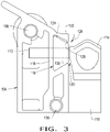
Fig. 3 is an end view of an embodiment of a side member and a strip used with the present disclosure; -
Fig. 4 is a perspective view of a portion of the side member shown inFig. 3 ; -
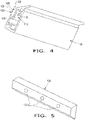
Fig. 5 is a perspective view of a portion of the strip shown inFig. 3 ; -
Fig. 6 is a perspective view of an embodiment of a corner piece of the present disclosure used for joining a side member with a cross member; and -
Fig. 7 is a perspective view of another embodiment of a corner piece of the present disclosure used for joining a side member with a cross member. - Corresponding reference characters indicate corresponding parts throughout the several views. The exemplifications set out herein illustrate embodiments of the invention, and such exemplifications are not to be construed as limiting the scope of the invention in any manner.
- The terms "grain", "straw" and "tailings" are used principally throughout this specification for convenience but it is to be understood that these terms are not intended to be limiting. Thus "grain" refers to that part of the crop material which is threshed and separated from the discardable part of the crop material, which is referred to as non-grain crop material, MOG or straw. Incompletely threshed crop material is referred to as "tailings". Also the terms "forward", "rearward", "left" and "right", when used in connection with the agricultural harvester and/or components thereof are usually determined with reference to the direction of forward operative travel of the harvester, but again, they should not be construed as limiting. The terms "longitudinal" and "transverse" are determined with reference to the fore-and-aft direction of the agricultural harvester and are equally not to be construed as limiting.
- Referring now to the drawings, and more particularly to
Fig. 1 , there is shown an agricultural harvester in the form of acombine 10, which generally includes achassis 12,ground engaging wheels header 18,feeder housing 20, operator cab 22, threshing and separatingsystem 24,cleaning system 26,grain tank 28, and unloadingauger 30. -
Front wheels 14 are larger flotation type wheels, andrear wheels 16 are smaller steerable wheels. Motive force is selectively applied tofront wheels 14 through a power plant in the form of adiesel engine 32 and a transmission (not shown). Althoughcombine 10 is shown as including wheels, is also to be understood that combine 10 may include tracks, such as full tracks or half tracks. -
Header 18 is mounted to the front ofcombine 10 and includes acutter bar 34 for severing crops from a field during forward motion ofcombine 10. Arotatable reel 36 feeds the crop intoheader 18, and adouble auger 38 feeds the severed crop laterally inwardly from each side towardfeeder housing 20.Feeder housing 20 conveys the cut crop to threshing and separatingsystem 24, and is selectively vertically movable using appropriate actuators, such as hydraulic cylinders (not shown). - Threshing and separating
system 24 is of the axial-flow type, and generally includes arotor 40 at least partially enclosed by and rotatable within a corresponding perforated concave 42. The cut crops are threshed and separated by the rotation ofrotor 40 within concave 42, and larger elements, such as stalks, leaves and the like are discharged from the rear ofcombine 10. Smaller elements of crop material including grain and non-grain crop material, including particles lighter than grain, such as chaff, dust and straw, are discharged through perforations of concave 42. Threshing and separatingsystem 24 can also be a different type of system, such as a system with a transverse rotor rather than an axial rotor, etc. - Grain which has been separated by the threshing and separating
assembly 24 falls onto agrain pan 44 and is conveyed towardcleaning system 26.Cleaning system 26 may include an optionalpre-cleaning sieve 46, an upper sieve 48 (also known as a chaffer sieve), a lower sieve 50 (also known as a cleaning sieve), and a cleaningfan 52. Theupper sieve 48 andlower sieve 50 can be carried within a common framework, and are generally designated together as sieve assembly 100, which will be described in more detail hereinafter. Grain onsieves fan 52 which provides an air flow through the sieves to remove chaff and other impurities such as dust from the grain by making this material airborne for discharge fromstraw hood 54 ofcombine 10.Grain pan 44 andpre-cleaning sieve 46 oscillate in a fore-to-aft manner to transport the grain and finer non-grain crop material to the upper surface ofupper sieve 48.Upper sieve 48 andlower sieve 50 are vertically arranged relative to each other, and likewise oscillate in a fore-to-aft manner to spread the grain acrosssieves sieves - Clean grain falls to a
clean grain auger 56 positioned crosswise below and toward the front oflower sieve 50.Clean grain auger 56 receives clean grain from eachsieve bottom pan 58 of cleaningsystem 26.Clean grain auger 56 conveys the clean grain laterally to a generally vertically arrangedgrain elevator 60 for transport tograin tank 28. Tailings from cleaningsystem 26 fall to atailings auger trough 62. The tailings are transported via tailings auger 64 and returnauger 66 to the upstream end of cleaningsystem 26 for repeated cleaning action. A pair ofgrain tank augers 68 at the bottom ofgrain tank 28 convey the clean grain laterally withingrain tank 28 to unloadingauger 30 for discharge fromcombine 10. - Referring now to
Figs. 2 and3 , the sieve assembly 100 includes a cleaning shoe 101 in which theupper sieve 48 andlower sieve 50 can be removably installed. Theupper sieve 48 andlower sieve 50 each generally include a framework 102 with a pair of opposed side members 104 (only one of which is visible for eachsieve Fig. 2 ). Afirst cross member 108 extends between theside members 104 at one end of theside members 104 and asecond cross member 110 extends between theside members 104 at an opposite end of theside members 104. In the embodiment shown, thefirst cross member 108 is positioned at the downstream end of thesieve second cross member 110 is positioned at the upstream end of thesieve - The
upper sieve 48 and thelower sieve 50 each include a plurality of louvres 112 (sometimes also referred to as wires) which extend between the pair ofopposed side members 104. The louvres 112 are pivotally mounted at opposite ends to theside members 104.
The plurality of louvres 112 each include awire 113 and a plurality offingers 114 attached to thewire 113. The plurality offingers 114 overlap relative to and can be offset from thefingers 114 of adj acent louvres. The spacing between thefingers 114 of adjacent louvres can be adjusted by simultaneously rotating the louvres within theside members 104. - The pair of opposed side members 104 (
Figs. 3 and4 ) are each comprised of an extruded metal side member with a partially openelongate channel 116 having a predefined cross section. In the illustrated embodiment, the extrudedmetal side members 104 are formed as extruded aluminum side members, for reduced weight while retaining adequate strength. Theelongate channel 116 can have a generally trapezoidal shaped cross section, with aclosed side 118 and anopen side 120. An elongate channel with a differently shaped cross section is also possible. Theelongate channel 116 includes adeformable lip 122 extending between theclosed side 118 and theopen side 120, which will be described in more detail below. - A strip 124 (
Figs. 3 and5 ) is carried within theelongate channel 116 and has a cross section which generally corresponds to and mates with the cross section of theelongate channel 116. Thestrip 124 is in an alternative material compared to the extrudedmetal side members 104, e.g. it can be a polymeric strip or another metal strip. Thedeformable lip 122 is compressed against thestrip 124 to hold thestrip 124 in place within theelongate channel 116. Thedeformable lip 122 can be bent against thestrip 124, as indicated bydirectional arrow 126, and may include adistal projection 128 that assists with gripping thestrip 124. - In the illustrated embodiment, the
strip 124 is configured as a polyamide strip providing suitable wear resistance and decreased friction properties. It may be possible to form thepolymeric strip 124 out of other suitable materials with similar physical properties, e.g. a metal like bronze. Eachpolymeric strip 124 extends substantially the length of the correspondingelongate channel 116 in which it is disposed. - The
strip 124 and theclosed side 118 each include a plurality of alignedholes 130 extending generally orthogonally from the open side 120 (Figs. 3 and4 ). Therespective wires 113 of the louvres 112 are rotatably carried within a corresponding one of the aligned holes 130. In contrast with a conventional sieve where the wires are rotatably carried in the thin plate steel of the side members, the plurality of alignedholes 130 in thepolymeric strip 124 provide an increased surface area with low friction for rotatably carrying a respective one of thewires 113. This in turn increases the operational life of the louvres 112. - The framework 102 can further include a plurality of cast
aluminum corner pieces side members 104 with one of thecross members 108, 110 (Figs. 6 and 7 ).Fasteners 136 fasten thecorner pieces extruded side members 104. Thecorner piece 132 shown inFig. 6 is at the front (downstream) end of the sieve assembly 100, and thecorner piece 134 shown inFig. 7 is at the rear (upstream) end of the sieve assembly 100. The castaluminum corner pieces - During assembly of the framework 102, the
strip 124 is slid into theelongate channel 116 and thedeformable lip 122 is bent into compression against thestrip 124. Theholes 130 are drilled through thepolymeric strip 124 andclosed side 118 at predetermined spacings therebetween, corresponding to the configuration of the louvres 112. Thewires 113 of the louvres 112 are placed into the corresponding aligned holes 130. Thecorner pieces side members 104 andcross members wires 113 of the louvres 112 can then be rotated within the alignedholes 130 with reduced friction and improved wear. - While this invention has been described with respect to at least one embodiment, the present invention can be further modified within the spirit and scope of this disclosure. This application is therefore intended to cover any variations, uses, or adaptations of the invention using its general principles. Further, this application is intended to cover such departures from the present disclosure as come within known or customary practice in the art to which this invention pertains and which fall within the limits of the appended claims.
Claims (11)
- A sieve (48, 50) for use in an agricultural harvester (10), the sieve (48, 50) comprising:a framework (102) including a pair of opposed side members (104);a plurality of overlapped louvres (112) extending between the pair of opposed side members (104) and being overlapped relative to each other;characterized by:
each of the opposed side members (104) being comprised of an extruded metal side member with a partially open elongate channel (116) having a predefined cross section, and a strip (124) having a mating cross section carried within the elongate channel (116). - The sieve (48, 50) of claim 1, wherein the elongate channel (116) has an open side (120) and an opposing closed side (118), and the strip (124) and the closed side (118) each include a plurality of aligned holes (130) extending generally orthogonally from the open side (120), and the plurality of louvres (112) each include a wire (113) and a plurality of fingers (114) attached to the wire (113), the respective wires (113) being rotatably carried within a corresponding one of the aligned holes (130).
- The sieve (48, 50) of claim 2, wherein each of the plurality of aligned holes (130) in the strip (124) provide an increased surface area with low friction for rotatably carrying a respective one of the wires (113).
- The sieve (48, 50) of claim 2, wherein the elongate channel (116) includes a deformable lip (122) extending between the closed side (118) and the open side (120), the deformable lip (122) being compressed against the strip (124) to hold the strip (124) in place within the elongate channel (116).
- The sieve (48, 50) of claim 4, wherein the elongate channel (116) has a generally trapezoidal shaped cross section.
- The sieve (48, 50) of claim 1, wherein each strip (124) extends substantially a length of the corresponding elongate channel (116).
- The sieve (48, 50) of claim 1, wherein the strip (124) comprises a polyamide strip or a bronze strip.
- The sieve (48, 50) of claim 1, wherein the extruded metal side members (104) comprise extruded aluminum side members.
- The sieve (48, 50) of claim 1, wherein the framework (102) further includes a pair of cross members (108, 110) extending between the side members (104), and further including a plurality of cast aluminum corner pieces (132, 134), each of the corner pieces (132, 134) interconnecting one of the side members (104) with one of the cross members (108, 110).
- A method of operating a sieve (48, 50) in an agricultural harvester (10), using the extruded metal side members (104) and respective strips (124) recited in claim 1.
- A method of assembling a sieve (48, 50) comprising the steps of:- positioning the extruded metal side member (104);- inserting the strip (124);- deforming the deformable lip (122) of the extruded side member (104); and- drilling a plurality of aligned holes through both the strip (124) and the extruded side member (104).
Priority Applications (4)
| Application Number | Priority Date | Filing Date | Title |
|---|---|---|---|
| EP21175435.3A EP4091431B1 (en) | 2021-05-21 | 2021-05-21 | Sieve for an agricultural harvester including extruded sides with strips |
| US17/748,251 US12419221B2 (en) | 2021-05-21 | 2022-05-19 | Sieve for an agricultural harvester including extruded sides with polymeric strips |
| BR102022009822-0A BR102022009822A2 (en) | 2021-05-21 | 2022-05-19 | SIEVE FOR USE IN AN AGRICULTURAL HARVESTER, AND METHODS OF OPERATING A SIEVE IN AN AGRICULTURAL HARVEST AND ASSEMBLING A SIEVE |
| CN202210558290.6A CN115362834B (en) | 2021-05-21 | 2022-05-20 | Screen for agricultural harvester and method of use and assembly thereof |
Applications Claiming Priority (1)
| Application Number | Priority Date | Filing Date | Title |
|---|---|---|---|
| EP21175435.3A EP4091431B1 (en) | 2021-05-21 | 2021-05-21 | Sieve for an agricultural harvester including extruded sides with strips |
Publications (2)
| Publication Number | Publication Date |
|---|---|
| EP4091431A1 true EP4091431A1 (en) | 2022-11-23 |
| EP4091431B1 EP4091431B1 (en) | 2025-12-03 |
Family
ID=76076225
Family Applications (1)
| Application Number | Title | Priority Date | Filing Date |
|---|---|---|---|
| EP21175435.3A Active EP4091431B1 (en) | 2021-05-21 | 2021-05-21 | Sieve for an agricultural harvester including extruded sides with strips |
Country Status (4)
| Country | Link |
|---|---|
| US (1) | US12419221B2 (en) |
| EP (1) | EP4091431B1 (en) |
| CN (1) | CN115362834B (en) |
| BR (1) | BR102022009822A2 (en) |
Citations (3)
| Publication number | Priority date | Publication date | Assignee | Title |
|---|---|---|---|---|
| DE1127135B (en) * | 1960-12-19 | 1962-04-05 | Graepel Friedrich | Lamella sieve for combine harvester |
| GB2054335A (en) * | 1979-08-01 | 1981-02-18 | Baggaley D J | Sieves |
| US20150087365A1 (en) * | 2013-09-20 | 2015-03-26 | Deere & Company | Hanger mount for a reciprocating sieve |
Family Cites Families (20)
| Publication number | Priority date | Publication date | Assignee | Title |
|---|---|---|---|---|
| US3081874A (en) | 1960-06-27 | 1963-03-19 | Orville Simpson Company | Screen tensioning device |
| US3334744A (en) * | 1965-09-22 | 1967-08-08 | Int Harvester Co | Sieve construction and the like |
| DE1757089A1 (en) * | 1968-03-29 | 1971-03-18 | Friedrich Graepel | Adjusting sieve (lamellar sieve) for combine harvester |
| GB2031302B (en) * | 1978-08-04 | 1982-06-30 | Baggaley D | Sieves |
| US4770190A (en) * | 1987-05-15 | 1988-09-13 | Deere & Company | Cleaning shoe screen for an agricultural combine having readily replaceable louvers |
| US5041059A (en) * | 1990-05-10 | 1991-08-20 | J. I. Case Company | Cleaning system for a combine |
| US5282771A (en) * | 1992-05-29 | 1994-02-01 | Probe Adventures, Inc. | Combine sieve levelling apparatus |
| US5338257A (en) * | 1992-05-29 | 1994-08-16 | Probe Adventures, Inc. | Combine sieve distributor apparatus |
| FR2739409B1 (en) | 1995-09-28 | 1997-12-12 | Alumafel | METHOD FOR MANUFACTURING A COMPOSITE JOINERY PROFILE AND COMPOSITE PROFILE OBTAINED |
| US6439392B1 (en) | 1997-09-02 | 2002-08-27 | Southwestern Wire Cloth, Inc. | Vibrating screen assembly with tubular frame |
| US20060270473A1 (en) * | 2004-08-19 | 2006-11-30 | James Straeter | Combine shoe with airflow-control |
| CN201911071U (en) * | 2010-10-22 | 2011-08-03 | 董明慧 | Rethreshing and cleaning device for whole-feed thresher |
| DE102010052816A1 (en) | 2010-11-29 | 2012-05-31 | Biso Schrattenecker Gmbh | Harvest header for a harvester |
| DE102012011891A1 (en) | 2012-06-15 | 2013-12-19 | Biso Schrattenecker Gmbh | Harvest header for a harvester |
| US9198359B2 (en) * | 2013-09-20 | 2015-12-01 | Deere & Company | Frame for a reciprocating sieve |
| BR102016017233B1 (en) * | 2015-07-23 | 2021-06-22 | Cnh Industrial America Llc | cleaning system for an agricultural combine harvester |
| BR102016017197B1 (en) * | 2015-07-23 | 2021-08-24 | Cnh Industrial America Llc | AGRICULTURAL SIEVE AND HARVESTER SET |
| DE102020109810A1 (en) * | 2020-04-08 | 2021-10-14 | Claas Selbstfahrende Erntemaschinen Gmbh | Harvester |
| CN111418357B (en) * | 2020-04-26 | 2025-08-29 | 江苏大学 | A multi-layer segmented regenerated rice grain cleaning sieve |
| AT524317B1 (en) * | 2021-06-08 | 2022-05-15 | Bartelmuss Ing Klaus | Drip bar and kit for use in a paper web forming installation |
-
2021
- 2021-05-21 EP EP21175435.3A patent/EP4091431B1/en active Active
-
2022
- 2022-05-19 BR BR102022009822-0A patent/BR102022009822A2/en unknown
- 2022-05-19 US US17/748,251 patent/US12419221B2/en active Active
- 2022-05-20 CN CN202210558290.6A patent/CN115362834B/en active Active
Patent Citations (3)
| Publication number | Priority date | Publication date | Assignee | Title |
|---|---|---|---|---|
| DE1127135B (en) * | 1960-12-19 | 1962-04-05 | Graepel Friedrich | Lamella sieve for combine harvester |
| GB2054335A (en) * | 1979-08-01 | 1981-02-18 | Baggaley D J | Sieves |
| US20150087365A1 (en) * | 2013-09-20 | 2015-03-26 | Deere & Company | Hanger mount for a reciprocating sieve |
Also Published As
| Publication number | Publication date |
|---|---|
| US20220369560A1 (en) | 2022-11-24 |
| BR102022009822A2 (en) | 2022-12-06 |
| US12419221B2 (en) | 2025-09-23 |
| CN115362834A (en) | 2022-11-22 |
| CN115362834B (en) | 2024-10-18 |
| EP4091431B1 (en) | 2025-12-03 |
Similar Documents
| Publication | Publication Date | Title |
|---|---|---|
| US11277969B2 (en) | Adjusting system for fingerstyle grates of an agricultural harvester | |
| EP3066910A1 (en) | Folding mechanism for wide wheat headers | |
| EP3092891B1 (en) | Chopper for an agricultural harvester | |
| US10368492B2 (en) | Rasp bar for a combine | |
| EP3120687A1 (en) | Side shaker link for agricultural harvester sieve assembly | |
| US20170318745A1 (en) | An agricultural harvester grain header auger | |
| EP3669639A1 (en) | Agricultural vehicle with adjustable rasp bars | |
| EP3245861B1 (en) | Threshing system with two banks of adjustable vanes on a cylindrical rotor cage of an agricultural harvester and method for controlling the vanes | |
| US12402567B2 (en) | Adjustment arrangement for offset spacing between louvres in a sieve of an agricultural harvester | |
| EP2996457B1 (en) | Cover plate for a clean grain auger in a cleaning system of an agricultural harvester | |
| US12514164B2 (en) | Adjustment arrangement for a sieve in an agricultural harvester | |
| US12484483B2 (en) | Sieve installation arrangement in a cleaning system of an agricultural harvester | |
| US12419221B2 (en) | Sieve for an agricultural harvester including extruded sides with polymeric strips | |
| US10058036B2 (en) | Structural members for a side shaking sieve arrangement in an agricultural harvester | |
| US12089535B2 (en) | Removable insert for a threshing rotor cage | |
| EP3479675B1 (en) | Rotor cage with flat walls for an agricultural vehicle | |
| US20250089621A1 (en) | Combine harvester having progressive separator vanes |
Legal Events
| Date | Code | Title | Description |
|---|---|---|---|
| PUAI | Public reference made under article 153(3) epc to a published international application that has entered the european phase |
Free format text: ORIGINAL CODE: 0009012 |
|
| STAA | Information on the status of an ep patent application or granted ep patent |
Free format text: STATUS: THE APPLICATION HAS BEEN PUBLISHED |
|
| AK | Designated contracting states |
Kind code of ref document: A1 Designated state(s): AL AT BE BG CH CY CZ DE DK EE ES FI FR GB GR HR HU IE IS IT LI LT LU LV MC MK MT NL NO PL PT RO RS SE SI SK SM TR |
|
| STAA | Information on the status of an ep patent application or granted ep patent |
Free format text: STATUS: REQUEST FOR EXAMINATION WAS MADE |
|
| 17P | Request for examination filed |
Effective date: 20230523 |
|
| RBV | Designated contracting states (corrected) |
Designated state(s): AL AT BE BG CH CY CZ DE DK EE ES FI FR GB GR HR HU IE IS IT LI LT LU LV MC MK MT NL NO PL PT RO RS SE SI SK SM TR |
|
| P01 | Opt-out of the competence of the unified patent court (upc) registered |
Effective date: 20240320 |
|
| GRAP | Despatch of communication of intention to grant a patent |
Free format text: ORIGINAL CODE: EPIDOSNIGR1 |
|
| STAA | Information on the status of an ep patent application or granted ep patent |
Free format text: STATUS: GRANT OF PATENT IS INTENDED |
|
| INTG | Intention to grant announced |
Effective date: 20250711 |
|
| GRAS | Grant fee paid |
Free format text: ORIGINAL CODE: EPIDOSNIGR3 |
|
| GRAA | (expected) grant |
Free format text: ORIGINAL CODE: 0009210 |
|
| STAA | Information on the status of an ep patent application or granted ep patent |
Free format text: STATUS: THE PATENT HAS BEEN GRANTED |
|
| AK | Designated contracting states |
Kind code of ref document: B1 Designated state(s): AL AT BE BG CH CY CZ DE DK EE ES FI FR GB GR HR HU IE IS IT LI LT LU LV MC MK MT NL NO PL PT RO RS SE SI SK SM TR |
|
| REG | Reference to a national code |
Ref country code: CH Ref legal event code: F10 Free format text: ST27 STATUS EVENT CODE: U-0-0-F10-F00 (AS PROVIDED BY THE NATIONAL OFFICE) Effective date: 20251203 Ref country code: GB Ref legal event code: FG4D |
|
| REG | Reference to a national code |
Ref country code: DE Ref legal event code: R096 Ref document number: 602021043462 Country of ref document: DE |
|
| REG | Reference to a national code |
Ref country code: IE Ref legal event code: FG4D |
|
| REG | Reference to a national code |
Ref country code: NL Ref legal event code: MP Effective date: 20251203 |
|
| PG25 | Lapsed in a contracting state [announced via postgrant information from national office to epo] |
Ref country code: ES Free format text: LAPSE BECAUSE OF FAILURE TO SUBMIT A TRANSLATION OF THE DESCRIPTION OR TO PAY THE FEE WITHIN THE PRESCRIBED TIME-LIMIT Effective date: 20251203 |
|
| REG | Reference to a national code |
Ref country code: LT Ref legal event code: MG9D |
|
| PG25 | Lapsed in a contracting state [announced via postgrant information from national office to epo] |
Ref country code: NO Free format text: LAPSE BECAUSE OF FAILURE TO SUBMIT A TRANSLATION OF THE DESCRIPTION OR TO PAY THE FEE WITHIN THE PRESCRIBED TIME-LIMIT Effective date: 20260303 |
|
| PG25 | Lapsed in a contracting state [announced via postgrant information from national office to epo] |
Ref country code: FI Free format text: LAPSE BECAUSE OF FAILURE TO SUBMIT A TRANSLATION OF THE DESCRIPTION OR TO PAY THE FEE WITHIN THE PRESCRIBED TIME-LIMIT Effective date: 20251203 Ref country code: HR Free format text: LAPSE BECAUSE OF FAILURE TO SUBMIT A TRANSLATION OF THE DESCRIPTION OR TO PAY THE FEE WITHIN THE PRESCRIBED TIME-LIMIT Effective date: 20251203 |
|
| PG25 | Lapsed in a contracting state [announced via postgrant information from national office to epo] |
Ref country code: RS Free format text: LAPSE BECAUSE OF FAILURE TO SUBMIT A TRANSLATION OF THE DESCRIPTION OR TO PAY THE FEE WITHIN THE PRESCRIBED TIME-LIMIT Effective date: 20260303 |
|
| PG25 | Lapsed in a contracting state [announced via postgrant information from national office to epo] |
Ref country code: PL Free format text: LAPSE BECAUSE OF FAILURE TO SUBMIT A TRANSLATION OF THE DESCRIPTION OR TO PAY THE FEE WITHIN THE PRESCRIBED TIME-LIMIT Effective date: 20251203 |
|
| PG25 | Lapsed in a contracting state [announced via postgrant information from national office to epo] |
Ref country code: LV Free format text: LAPSE BECAUSE OF FAILURE TO SUBMIT A TRANSLATION OF THE DESCRIPTION OR TO PAY THE FEE WITHIN THE PRESCRIBED TIME-LIMIT Effective date: 20251203 |
|
| PG25 | Lapsed in a contracting state [announced via postgrant information from national office to epo] |
Ref country code: BG Free format text: LAPSE BECAUSE OF FAILURE TO SUBMIT A TRANSLATION OF THE DESCRIPTION OR TO PAY THE FEE WITHIN THE PRESCRIBED TIME-LIMIT Effective date: 20251203 |