EP4090258B1 - Helical cardiac anchors for minimally invasive heart valve repair - Google Patents
Helical cardiac anchors for minimally invasive heart valve repair Download PDFInfo
- Publication number
- EP4090258B1 EP4090258B1 EP21741951.4A EP21741951A EP4090258B1 EP 4090258 B1 EP4090258 B1 EP 4090258B1 EP 21741951 A EP21741951 A EP 21741951A EP 4090258 B1 EP4090258 B1 EP 4090258B1
- Authority
- EP
- European Patent Office
- Prior art keywords
- anchor
- suture
- hub
- spring
- heart
- Prior art date
- Legal status (The legal status is an assumption and is not a legal conclusion. Google has not performed a legal analysis and makes no representation as to the accuracy of the status listed.)
- Active
Links
Images












Classifications
-
- A—HUMAN NECESSITIES
- A61—MEDICAL OR VETERINARY SCIENCE; HYGIENE
- A61B—DIAGNOSIS; SURGERY; IDENTIFICATION
- A61B17/00—Surgical instruments, devices or methods
- A61B17/04—Surgical instruments, devices or methods for suturing wounds; Holders or packages for needles or suture materials
- A61B17/0401—Suture anchors, buttons or pledgets, i.e. means for attaching sutures to bone, cartilage or soft tissue; Instruments for applying or removing suture anchors
-
- A—HUMAN NECESSITIES
- A61—MEDICAL OR VETERINARY SCIENCE; HYGIENE
- A61F—FILTERS IMPLANTABLE INTO BLOOD VESSELS; PROSTHESES; DEVICES PROVIDING PATENCY TO, OR PREVENTING COLLAPSING OF, TUBULAR STRUCTURES OF THE BODY, e.g. STENTS; ORTHOPAEDIC, NURSING OR CONTRACEPTIVE DEVICES; FOMENTATION; TREATMENT OR PROTECTION OF EYES OR EARS; BANDAGES, DRESSINGS OR ABSORBENT PADS; FIRST-AID KITS
- A61F2/00—Filters implantable into blood vessels; Prostheses, i.e. artificial substitutes or replacements for parts of the body; Appliances for connecting them with the body; Devices providing patency to, or preventing collapsing of, tubular structures of the body, e.g. stents
- A61F2/02—Prostheses implantable into the body
- A61F2/24—Heart valves ; Vascular valves, e.g. venous valves; Heart implants, e.g. passive devices for improving the function of the native valve or the heart muscle; Transmyocardial revascularisation [TMR] devices; Valves implantable in the body
- A61F2/2442—Annuloplasty rings or inserts for correcting the valve shape; Implants for improving the function of a native heart valve
- A61F2/2454—Means for preventing inversion of the valve leaflets, e.g. chordae tendineae prostheses
- A61F2/2457—Chordae tendineae prostheses
-
- A—HUMAN NECESSITIES
- A61—MEDICAL OR VETERINARY SCIENCE; HYGIENE
- A61B—DIAGNOSIS; SURGERY; IDENTIFICATION
- A61B17/00—Surgical instruments, devices or methods
- A61B17/00234—Surgical instruments, devices or methods for minimally invasive surgery
- A61B2017/00292—Surgical instruments, devices or methods for minimally invasive surgery mounted on or guided by flexible, e.g. catheter-like, means
- A61B2017/003—Steerable
- A61B2017/00305—Constructional details of the flexible means
- A61B2017/00309—Cut-outs or slits
-
- A—HUMAN NECESSITIES
- A61—MEDICAL OR VETERINARY SCIENCE; HYGIENE
- A61B—DIAGNOSIS; SURGERY; IDENTIFICATION
- A61B17/00—Surgical instruments, devices or methods
- A61B17/04—Surgical instruments, devices or methods for suturing wounds; Holders or packages for needles or suture materials
- A61B17/0401—Suture anchors, buttons or pledgets, i.e. means for attaching sutures to bone, cartilage or soft tissue; Instruments for applying or removing suture anchors
- A61B2017/0409—Instruments for applying suture anchors
-
- A—HUMAN NECESSITIES
- A61—MEDICAL OR VETERINARY SCIENCE; HYGIENE
- A61B—DIAGNOSIS; SURGERY; IDENTIFICATION
- A61B17/00—Surgical instruments, devices or methods
- A61B17/04—Surgical instruments, devices or methods for suturing wounds; Holders or packages for needles or suture materials
- A61B17/0401—Suture anchors, buttons or pledgets, i.e. means for attaching sutures to bone, cartilage or soft tissue; Instruments for applying or removing suture anchors
- A61B2017/0414—Suture anchors, buttons or pledgets, i.e. means for attaching sutures to bone, cartilage or soft tissue; Instruments for applying or removing suture anchors having a suture-receiving opening, e.g. lateral opening
-
- A—HUMAN NECESSITIES
- A61—MEDICAL OR VETERINARY SCIENCE; HYGIENE
- A61B—DIAGNOSIS; SURGERY; IDENTIFICATION
- A61B17/00—Surgical instruments, devices or methods
- A61B17/04—Surgical instruments, devices or methods for suturing wounds; Holders or packages for needles or suture materials
- A61B17/0401—Suture anchors, buttons or pledgets, i.e. means for attaching sutures to bone, cartilage or soft tissue; Instruments for applying or removing suture anchors
- A61B2017/0427—Suture anchors, buttons or pledgets, i.e. means for attaching sutures to bone, cartilage or soft tissue; Instruments for applying or removing suture anchors having anchoring barbs or pins extending outwardly from the anchor body
-
- A—HUMAN NECESSITIES
- A61—MEDICAL OR VETERINARY SCIENCE; HYGIENE
- A61B—DIAGNOSIS; SURGERY; IDENTIFICATION
- A61B17/00—Surgical instruments, devices or methods
- A61B17/04—Surgical instruments, devices or methods for suturing wounds; Holders or packages for needles or suture materials
- A61B17/0401—Suture anchors, buttons or pledgets, i.e. means for attaching sutures to bone, cartilage or soft tissue; Instruments for applying or removing suture anchors
- A61B2017/044—Suture anchors, buttons or pledgets, i.e. means for attaching sutures to bone, cartilage or soft tissue; Instruments for applying or removing suture anchors with a threaded shaft, e.g. screws
- A61B2017/0441—Suture anchors, buttons or pledgets, i.e. means for attaching sutures to bone, cartilage or soft tissue; Instruments for applying or removing suture anchors with a threaded shaft, e.g. screws the shaft being a rigid coil or spiral
-
- A—HUMAN NECESSITIES
- A61—MEDICAL OR VETERINARY SCIENCE; HYGIENE
- A61B—DIAGNOSIS; SURGERY; IDENTIFICATION
- A61B17/00—Surgical instruments, devices or methods
- A61B17/04—Surgical instruments, devices or methods for suturing wounds; Holders or packages for needles or suture materials
- A61B17/0401—Suture anchors, buttons or pledgets, i.e. means for attaching sutures to bone, cartilage or soft tissue; Instruments for applying or removing suture anchors
- A61B2017/044—Suture anchors, buttons or pledgets, i.e. means for attaching sutures to bone, cartilage or soft tissue; Instruments for applying or removing suture anchors with a threaded shaft, e.g. screws
- A61B2017/0443—Suture anchors, buttons or pledgets, i.e. means for attaching sutures to bone, cartilage or soft tissue; Instruments for applying or removing suture anchors with a threaded shaft, e.g. screws the shaft being resilient and having a coiled or helical shape in the released state
-
- A—HUMAN NECESSITIES
- A61—MEDICAL OR VETERINARY SCIENCE; HYGIENE
- A61B—DIAGNOSIS; SURGERY; IDENTIFICATION
- A61B17/00—Surgical instruments, devices or methods
- A61B17/04—Surgical instruments, devices or methods for suturing wounds; Holders or packages for needles or suture materials
- A61B17/0401—Suture anchors, buttons or pledgets, i.e. means for attaching sutures to bone, cartilage or soft tissue; Instruments for applying or removing suture anchors
- A61B2017/0446—Means for attaching and blocking the suture in the suture anchor
- A61B2017/0448—Additional elements on or within the anchor
-
- A—HUMAN NECESSITIES
- A61—MEDICAL OR VETERINARY SCIENCE; HYGIENE
- A61B—DIAGNOSIS; SURGERY; IDENTIFICATION
- A61B17/00—Surgical instruments, devices or methods
- A61B17/04—Surgical instruments, devices or methods for suturing wounds; Holders or packages for needles or suture materials
- A61B17/0401—Suture anchors, buttons or pledgets, i.e. means for attaching sutures to bone, cartilage or soft tissue; Instruments for applying or removing suture anchors
- A61B2017/0446—Means for attaching and blocking the suture in the suture anchor
- A61B2017/0454—Means for attaching and blocking the suture in the suture anchor the anchor being crimped or clamped on the suture
-
- A—HUMAN NECESSITIES
- A61—MEDICAL OR VETERINARY SCIENCE; HYGIENE
- A61B—DIAGNOSIS; SURGERY; IDENTIFICATION
- A61B17/00—Surgical instruments, devices or methods
- A61B17/04—Surgical instruments, devices or methods for suturing wounds; Holders or packages for needles or suture materials
- A61B17/0401—Suture anchors, buttons or pledgets, i.e. means for attaching sutures to bone, cartilage or soft tissue; Instruments for applying or removing suture anchors
- A61B2017/0464—Suture anchors, buttons or pledgets, i.e. means for attaching sutures to bone, cartilage or soft tissue; Instruments for applying or removing suture anchors for soft tissue
-
- A—HUMAN NECESSITIES
- A61—MEDICAL OR VETERINARY SCIENCE; HYGIENE
- A61F—FILTERS IMPLANTABLE INTO BLOOD VESSELS; PROSTHESES; DEVICES PROVIDING PATENCY TO, OR PREVENTING COLLAPSING OF, TUBULAR STRUCTURES OF THE BODY, e.g. STENTS; ORTHOPAEDIC, NURSING OR CONTRACEPTIVE DEVICES; FOMENTATION; TREATMENT OR PROTECTION OF EYES OR EARS; BANDAGES, DRESSINGS OR ABSORBENT PADS; FIRST-AID KITS
- A61F2220/00—Fixations or connections for prostheses classified in groups A61F2/00 - A61F2/26 or A61F2/82 or A61F9/00 or A61F11/00 or subgroups thereof
- A61F2220/0008—Fixation appliances for connecting prostheses to the body
- A61F2220/0016—Fixation appliances for connecting prostheses to the body with sharp anchoring protrusions, e.g. barbs, pins, spikes
-
- A—HUMAN NECESSITIES
- A61—MEDICAL OR VETERINARY SCIENCE; HYGIENE
- A61F—FILTERS IMPLANTABLE INTO BLOOD VESSELS; PROSTHESES; DEVICES PROVIDING PATENCY TO, OR PREVENTING COLLAPSING OF, TUBULAR STRUCTURES OF THE BODY, e.g. STENTS; ORTHOPAEDIC, NURSING OR CONTRACEPTIVE DEVICES; FOMENTATION; TREATMENT OR PROTECTION OF EYES OR EARS; BANDAGES, DRESSINGS OR ABSORBENT PADS; FIRST-AID KITS
- A61F2230/00—Geometry of prostheses classified in groups A61F2/00 - A61F2/26 or A61F2/82 or A61F9/00 or A61F11/00 or subgroups thereof
- A61F2230/0063—Three-dimensional shapes
- A61F2230/0091—Three-dimensional shapes helically-coiled or spirally-coiled, i.e. having a 2-D spiral cross-section
Definitions
- the present invention relates to minimally invasive delivery of a suture into the heart. More particularly, the disclosed embodiments relate to inserting and anchoring one or more sutures as artificial chordae tendineae for a flailing or prolapsing leaflet in a beating heart.
- the mitral and tricuspid valves inside the human heart include an orifice (annulus), two (for the mitral) or three (for the tricuspid) leaflets and a subvalvular apparatus.
- the subvalvular apparatus includes multiple chordae tendineae, which connect the mobile valve leaflets to muscular structures (papillary muscles) inside the ventricles. Rupture or elongation of the chordae tendineae results in partial or generalized leaflet prolapse, which causes mitral (or tricuspid) valve regurgitation.
- a commonly used technique to surgically correct mitral valve regurgitation is the implantation of artificial chordae (usually 4-0 or 5-0 Gore-Tex sutures) between the prolapsing segment of the valve and the papillary muscle.
- This technique for implantation of artificial chordae was traditionally done by an open heart operation generally carried out through a median sternotomy and requiring cardiopulmonary bypass with aortic cross-clamp and cardioplegic arrest of the heart.
- an open heart operation generally carried out through a median sternotomy and requiring cardiopulmonary bypass with aortic cross-clamp and cardioplegic arrest of the heart.
- the large opening provided by a median sternotomy or right thoracotomy enables the surgeon to see the mitral valve directly through the left atriotomy, and to position his or her hands within the thoracic cavity in close proximity to the exterior of the heart for manipulation of surgical instruments, removal of excised tissue, and/or introduction of an artificial chordae through the atriotomy for attachment within the heart.
- U.S. Patent No. 8,465,500 to Speziali discloses a thoracoscopic heart valve repair method and apparatus. Instead of requiring open heart surgery on a stopped heart, the thoracoscopic heart valve repair methods and apparatus taught by Speziali utilize fiber optic technology in conjunction with transesophageal echocardiography (TEE) as a visualization technique during a minimally invasive surgical procedure that can be utilized on a beating heart. More recent versions of these techniques are disclosed in U.S. Patent Nos.
- TEE transesophageal echocardiography
- Some systems have therefore been proposed that utilize a catheter routed through the patient's vasculature to enter the heart and attach a suture to a heart valve leaflet as an artificial chordae. While generally less invasive than the approaches discussed above, transcatheter heart valve repair can provide additional challenges. For example, with all artificial chordae replacement procedures, in addition to inserting a suture through a leaflet, the suture must also be anchored at a second location, such as at a papillary muscle in the heart, with a suture length, and tension and positioning of the suture should be adjustable to enable the valve to function naturally. If the suture is too short and/or has too much tension, the valve leaflets may not properly close.
- US2010/161041A1 relates to a method, including implanting, at an intraventricular site of a ventricle of a patient, a spool coupled to a first end portion of a longitudinal member, and coupling a second end portion of the longitudinal member to a portion of tissue facing a lumen of the ventricle.
- an anchor assembly is configured to implant a cardiac anchor into a heart wall of a patient to anchor a suture configured to extend from a valve leaflet of the heart as an artificial chordae.
- the anchor assembly can include an anchor hub defining an open interior and a helical coil extending distally from the anchor hub and having a sharpened tip configured to embed the helical coil into the heart wall upon rotation of the helical coil.
- a spring can be disposed within the open interior of the anchor hub. Compressing the spring distally can create an open space within the open interior of the anchor hub for a suture extending through the anchor hub to slide freely and releasing compression on the spring can cause the spring to expand in a proximal direction to clamp the suture within the open interior of the anchor hub.
- an anchor assembly is configured to implant a cardiac anchor into a heart wall of a patient to anchor a suture configured to extend from a valve leaflet of the heart as an artificial chordae.
- Anchor assembly can include an anchor base and a helical coil extending distally from the anchor base and having a sharpened tip configured to embed the helical coil into the heart wall upon rotation of the helical coil.
- a stabilizing needle can extend longitudinally through and distally beyond the helical coil and have a sharpened tip configured to pierce the heart wall to stabilize the helical coil for insertion of the helical coil into the heart wall.
- a suture clamp can be configured to be rotated to clamp a suture under tension between the suture clamp and the anchor base.
- the suture clamp can include an anchor washer movable along a body of the anchor base and configured to have a suture inserted through a space between the anchor washer and the body of the anchor base and an anchor clamp nut threadedly attached to the anchor base. Rotation of the anchor clamp nut in a first direction can move the anchor clamp nut distally to clamp a suture inserted through the space between the anchor washer and the body of the anchor base between the anchor base and the anchor washer and between the anchor clamp nut and the anchor washer.
- an anchor assembly is configured to implant a cardiac anchor into a heart wall of a patient to anchor a suture configured to extend from a valve leaflet of the heart as an artificial chordae.
- the anchor assembly can include a suture anchor including an anchor hub, a helical coil extending distally from the anchor hub and having a sharpened tip configured to embed the helical coil into the heart wall upon rotation of the helical coil, and a suture lock threadedly attached to a proximal end of the anchor hub.
- the assembly can include an anchor hub driver having a drive end configured to mate with the anchor hub and an anchor hub driver tube configured to be rotated to rotate the suture anchor for insertion into the heart wall.
- the assembly can further include a suture lock driver having a drive end configured to mate with the suture lock and a suture lock driver tube, such that rotation of the suture lock driver in a first direction moves the suture lock distally to clamp a suture between the suture lock and the anchor hub.
- the suture lock can include a suture locking wedge including a threaded distal portion configured to interface with a threaded distal portion of the anchor hub and a tapered clamping surface configured to clamp the suture between a chamfered interior surface of the anchor hub and the tapered clamping surface of the suture locking wedge.
- an anchor assembly is configured to implant a cardiac anchor into a heart wall of a patient to anchor a suture configured to extend from a valve leaflet of the heart as an artificial chordae.
- the anchor assembly can include a suture anchor including an anchor hub, a helical coil extending distally from the anchor hub and having a sharpened tip configured to embed the helical coil into the heart wall upon rotation of the helical coil.
- a stabilizing needle extending longitudinally through and distally beyond the helical coil has a sharpened tip configured to pierce the heart wall to stabilize the helical coil for insertion of the helical coil into the heart wall.
- An anchor delivery assembly can include an anchor driver configured to mate with the anchor hub to rotate the suture anchor for insertion into the heart wall.
- a suture lock delivery system can include a lock carrier configured to mate with the anchor hub and to carry a suture lock and a pusher movable with respect to the lock carrier. The pusher can be configured to push the suture lock off of the lock carrier and onto the anchor hub to clamp a suture between the suture lock and the anchor hub.
- the suture lock is configured as a spring.
- an anchor assembly is configured to implant a cardiac anchor into a heart wall of a patient to anchor a suture configured to extend from a valve leaflet of the heart as an artificial chordae.
- the anchor assembly can include an anchor hub defining an open interior and a proximal end cap covering the open interior.
- a helical coil can extend distally from the anchor base and have a sharpened tip configured to embed the helical coil into the heart wall upon rotation of the helical coil.
- a stabilizing needle can extend longitudinally through and distally beyond the anchor hub and the helical coil.
- the stabilizing needle can have a sharpened tip configured to pierce the heart wall to stabilize the helical coil for insertion of the helical coil into the heart wall and a threaded proximal portion rotatingly attached to the end cap of the anchor hub.
- a piston chamber can be disposed within the open interior of the anchor hub, with the piston chamber and the end cap each having one or more openings enabling one or more sutures to pass through the piston chamber and the end cap.
- a spring can be disposed within the piston chamber between a proximal end of the piston chamber and a distal end of the anchor hub such that the spring biases the piston chamber proximally towards the end cap.
- Rotation of the stabilizing needle in a first direction can move the piston chamber distally to compress the spring to provide space between the piston chamber and the end cap for a suture to move freely and rotation of the stabilizing needle in a second direction can move the piston chamber proximally to clamp the suture between the piston chamber and the end cap.
- the present disclosure is generally directed to inserting and anchoring one or more sutures as artificial chordae into one or more heart valve leaflets through an intravascular, transcatheter approach.
- a heart valve leaflet may be captured and a suture inserted through the leaflet in any manner known in the art. Examples of such leaflet capture catheters are disclosed in copending U.S. Patent Publication No. 2019/0290260 and U.S. Patent Application No. 16/564,887 .
- Other transcatheter procedures for inserting an artificial chordae are disclosed in U.S. Patent Publication No. 2016/0143737 and U.S. Patent Application No. 16/745,074 .
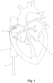
- FIG. 1 depicts a schematic representation of an embodiment of an access approach for a heart valve repair system accessing the mitral valve 10.
- Figure 1 depicts a guide catheter 14 accessing the interior of the heart via the femoral vein.
- such a system can further include an outer guide catheter and an inner guide catheter.
- the outer guide catheter can be inserted into the femoral vein at the patient's groin and advanced through the femoral vein into the inferior vena cava 19 and then into the right atrium 16.
- the outer guide catheter can be steerable in a single plane and can have an outer diameter of about or less than about 30 French, such as, for example 24 French.
- the septum 18 can then be punctured using an appropriate puncture tool and the outer guide catheter advanced into the septum 18 or through the septum 18 into the left atrium 20.
- the inner guide catheter can then be axially advanced through the outer guide catheter into the left atrium 20.
- the inner guide catheter can have two plans of steerability and can be maneuvered along with and/or beyond the outer guide catheter to establish a stable position superior to the mitral valve 10 and to provide a desired trajectory for operation of a leaflet capture catheter to repair the valve.
- anchors as described herein may be implanted through other intravascular approaches as well as non-intravascular approaches.
- Anchor assembly 100 includes an anchor coil 100 that embeds the anchor assembly 100 into heart tissue and, in some embodiments, a central stabilizing needle 104 extending longitudinally through the coil 102 to stabilize the anchor assembly 100 while the coil 102 is driven into the tissue.
- An anchor base 106 can connected to the anchor coil 102 and the stabilizing needle 104.
- Anchor assembly 100 can further include a plurality of suture clamping components, including an anchor washer 108, an anchor clamp ring 110, an anchor clamp nut 112, an anchor clamp nut cap 114, an anchor clamp nut driver 116 and an anchor cap 118, which will be described in more detail below.
- An anchor sheath 124 is used to deliver and cover the anchor assembly 100 before it is deployed and the components of the anchor assembly 100 are actuated with an anchor tether 120 and an anchor driver tube 122 as will also be described in more detail below.
- stabilizing needle 104 can include a sharp tip 126 capable of piercing the tissue of the heart wall. By piercing the heart wall with stabilizing needle 104, the anchor assembly is stably held in position to enable the anchor coil 104 to be embedded into the heart wall to anchor the assembly by rotating anchor assembly 100.
- a proximal threaded end 128 of the stabilizing needle 104 can be configured to be to be connected to anchor base 106. The proximal threaded end 128 can also be drilled out to provide a hollow interior configured to enable the tether 120 to be attached thereto such as, for example, by laser welding.
- anchor assembly 100 can be provided without stabilizing needle 104.
- a stabilizing needle can alternatively be provided with an anchor delivery catheter, as described below with respect to Figures 15A-15H .
- Anchor coil 102 includes a distal tip 130 for piercing the tissue of the heart wall.
- the anchor coil 102 is configured to be rotated clockwise to screw into the tissue.
- Anchor coil 102 can further be provided with anti-backout features, such as one or more barbs, that prevent rotation of anchor coil 102 due to natural heart rhythms from backing the coil out of the tissue.
- the anchor coil 102 can be connected to the anchor base 106 such as, for example, by laser welding.
- the inside diameter of the anchor base 106 can be drilled out to create a hollow passage 132 to receive the proximal portion of the stabilizing needle, including an internally and externally threaded portion 134 that internally interfaces with the proximal threaded end 128 of the stabilizing needle 104.
- a chamfer surface 136 of anchor base 106 that is longitudinally angled with respect to the assembly functions as one of the clamping surfaces for clamping the suture.
- the anchor washer 108 is not threaded or welded to any component.
- the washer 108 can float rotationally and axially unconstrained on the shaft 138 of the anchor base.
- Anchor washer 108 functions to clamp the suture between the anchor base 106 and the anchor clamp ring 110.
- the anchor clamp ring 110 is similarly not threaded or welded onto any component and can axially float on the anchor base shaft 138 but is rotationally constrained on the anchor base 106.
- Anchor clamp ring 110 is prevented from rotating because it interfaces directly with the suture (which does not rotate) but is pushed down by the anchor clamp nut 112 (which rotates while threading down on the anchor base).
- anchor clamp ring 110 can be prevented from rotating by cutting off the outer threads on two sides of the anchor base 102.
- the anchor clamp nut 112 includes internal threading 140 to rotationally attach the anchor clamp nut 112 to the external threading of threaded portion 134 of anchor base 106. As the anchor clamp nut 112 is rotated counterclockwise, it moves down along the threading of threaded portion 134 to clamp the suture.
- the anchor clamp nut cap 114 interfaces with an open proximal end 142 of the anchor clamp nut 112 and can be attached, e.g., by laser welding, after the anchor clamp nut 112 is threaded on to the anchor base 106 to lock the anchor clamp nut 112 on and prevent removal of the anchor clamp nut 112 from the anchor base 106.
- the anchor clamp driver 116 can be attached such as by laser welding onto the anchor clamp nut cap 114 with a drive end 146 (e.g., a hex drive) of the anchor clamp driver 116 interfacing with a correspondingly shaped aperture 144 in the anchor clamp nut cap 114.
- the anchor cap 118 can be attached to the anchor base 106, such as by laser welding, after the anchor washer 108, anchor clamp ring 110 and anchor clamp nut 112 have been assembled with anchor base 106, which locks anchor clamp nut 112 onto anchor base 106 to eliminate the risk of accidentally threading the anchor clamp nut 112 back off of the anchor base 106.
- the anchor tether 120 can be a flexible, generally cylindrical component that can travel through the anchor driver tube 122 and the anchor base 106 and be attached to the stabilizing needle 104 by, for example, laser welding.
- tether 120 is a Nitinol wire.
- the anchor 100 is driven into tissue by twisting the anchor tether 120 clockwise, with the torque being transferred from the anchor tether 120 to the stabilizing needle 102 and the anchor base 106 to which the anchor coil 102 is attached, thus causing rotation of the anchor coil 102 to embed the coil into tissue.
- the anchor tether 120 can attach to and directly rotate the anchor base 106.
- the anchor driver tube 122 is attached to the anchor clamp nut cap 114 such that rotation of the anchor driver tube 122 causes rotation of the anchor clamp nut 112 to move the anchor clamp nut 122 along the threaded portion 134 of the anchor base 106 to clamp the suture between the anchor base 106, anchor washer 108 and anchor clamp ring 110.
- the suture 30 is threaded through the anchor washer 108 and is clamped therein between chamfer surface 136 of anchor base 106 and anchor clamp ring 110.
- the anchor sheath 124 covers the anchor coil 102 before the anchor 100 is deployed.
- the anchor sheath 124 can include a slit 148 on one side of anchor sheath 124 that enables the suture to access the anchor locking components and then enter the anchor sheath proximal to the anchor. Following seating of the anchor in the heart wall, the anchor driver tube 122 and anchor cap 118 and then the tether 120 and stabilizing needle 104 can be withdrawn by twisting the tether counter-clockwise.
- suture 30 is threaded through anchor washer 108 outside of the body.
- the anchor 100 is inserted into anchor sheath 124 and delivered into the heart such that the suture 30 extends through anchor sheath 124 back out of the body to enable suture 30 tension to be adjusted from outside the body.
- the anchor clamp nut 112 is tightened, the suture is clamped between the chamfer surface 136 of anchor base and the distal side of anchor washer 108 and between the anchor clamp ring 110 and the proximal side of anchor washer 108 to securely hold the suture 30 at a desired tension.
- FIG. 30 Although depicted as a single suture 30, it should be understood that a plurality of sutures could be locked in this manner.
- FIGS 4A-4C depict schematic representations of various steps of a method of repairing a heart valve according to another embodiment that utilizes anchor system 100.
- the anchor 100 can then be inserted into anchor delivery catheter or sheath 124 and positioned adjacent the heart wall.
- the stabilizing needle 104 first pierces the tissue to stabilize the anchor while the coil 102 is driven into the tissue by rotating the anchor 100 as described above.
- the sutures can be tensioned and then locked by rotating an anchor clamp nut 112 to clamp down on the sutures 30.
- the stabilizing needle 104 can then be removed and the sutures ends severed as depicted in Figure 4C .
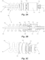
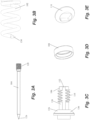
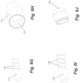
- FIGS 5A-5C depict various views of an anchor assembly 200 for anchoring a suture as an artificial chordae in a heart wall of a patient and Figures 6A-6J depict the various components thereof.
- Anchor assembly 200 includes an anchor coil 202 configured to embed the anchor into the tissue of the heart wall and a suture locking system that locks one or more sutures at a set tension for proper valve function.
- Anchor coil 202 includes a sharpened distal tip 222 configured to pierce the tissue and is configured to be embedded into the heart wall by clockwise rotation and can be used with anti-backout features, such as one or more barbs.
- the anchor coil 202 is connected to the anchor hub 204, such as, for example, by laser welding.
- the anchor hub 204 includes a proximal drive end 224 such, as for, example a hex drive configured to interface with an anchor hub driver 216 to enable rotation of the hub 204 and coil 202.
- the anchor hub 204 can further include an interior threaded portion 226 at a distal portion of the anchor hub 204 and an interior chamfered chamber 228 at a proximal portion thereof.
- Suture locking wedge 206 includes a distal threaded portion 230 configured to interface with the interior threaded portion 226 of anchor hub 204.
- a tapered outer surface 232 of suture locking wedge 206 interfaces with the interior chamfered chamber 228 of the anchor hub to lock the suture between the two surfaces.
- a hollow longitudinal chamber 234 extends from distal threaded portion 230 of suture locking wedge 206 and is in communication with a cross aperture 236 through tapered outer surface 232. As can be seen in Figure 2C , this enables one or more sutures 30 to extend proximally up through anchor coil 202, through the hollow chamber 234 and out of the cross apertures 236 of anchor base and back proximally through the device.
- suture locking wedge 206 can further include a drive end 238, such as a hex drive, to interface with a suture lock driver 212.
- the center of the drive end 238 can include internal threading 240 to interface with a threaded distal end 242 of tether crimp 208.
- Proximal portion 244 of tether crimp includes a drilled out hollow chamber that is crimped onto the tether 210.
- tether 210 is a Nitinol wire that is, for example, 0.015 inches in diameter. The tether crimp 208 and tether 210 are fastened to the suture locking wedge 206 to ensure that the anchor is not prematurely released.
- Suture lock driver 212 has a drive end 248 with an internal geometry, e.g., hex, matching that of the drive end 238 of the suture locking wedge 206. In embodiments, the two components interface with a slip fit. Suture lock driver 212 further includes two open sides 250 that enable sutures to enter suture lock driver 212 and exit out of a proximal aperture 252. Suture lock driver 212 is connected to suture lock driver tube 214 such as, for example, by laser welding. Suture lock driver 212 can be rotated clockwise via suture lock driver tube 214 to move the suture locking wedge 206 distally to clamp the suture 30 between the suture locking wedge 206 and the anchor hub 204. In some embodiments, suture lock driver tube 214 can be laser cut at lines 254 to provided added flexibility for maneuvering the device through the vasculature and to reduce torque buildup on the distal portion of the system.
- Anchor hub driver 216 includes a drive end 256 with an internal geometry, e.g., hex, matching that of the drive end 224 of the anchor hub 204. Rotating of the anchor hub driver 216 via the anchor hub driver tube 218 in a clockwise direction rotates the anchor hub 204 and the anchor coil 202 to embed the anchor coil 202 into the heart tissue. Applying a counter-force on the anchor hub 204 with the anchor hub driver 216 can also provide a counter-torque when applying a final torque to the suture locking wedge 206 with the suture lock driver 212 to lock the sutures within the anchor hub 204 with the suture locking wedge 206.
- an internal geometry e.g., hex
- FIG. 5C the routing of sutures 30 through anchor system is depicted (in which a pair of sutures is depicted, by fewer or greater sutures could be employed).
- the ends of the suture 30 are threaded through anchor system 200 such that they extend back through anchor coil 202 and anchor hub 204, into the distal chamber 234 and out of the cross aperture 236 of the suture locking wedge 206, and back through suture lock driver 212, suture lock drive tube 214 and anchor hug drive tube 218 to be able to be tensioned from outside of the body.
- the suture locking wedge 206 is advanced distally, the sutures 30 are clamped between the tapered surface 232 of the suture locking wedge 206 and the chamfered chamber 228 of the anchor hub 204 to lock the suture at a desired tension.
- FIGS 7A-7D depict schematic representations of various steps of a method of repairing a heart valve according to another embodiment that also utilizes anchor system 200.
- the sutures 30 can be threaded through the anchor coil 202 and anchor body 704 of anchor exterior to the body.
- Anchor catheter 223 can then be used to deliver the anchor system 200 to the heart wall.
- the anchor hub driver 216 can then be used with the anchor hub driver tube 218 to rotate the anchor to 200 embed the coil 202 into the heart wall.
- the suture 30 slides through the coil and to the anchor hub 204 once the coil is full inserted into the tissue.
- the anchor hub driver 216 and anchor hub driver tube 218 can then be withdrawn above as depicted in Figure 7B .
- the suture lock driver 212 and anchor hub driver 216 can then be withdrawn, leaving tether 210 extending from the anchor 200 back out of the heart.
- the free ends of the suture 30 can then be severed and a suture cover 220 can be advanced along the tether 210 to be seated on the anchor hub 204 to cover sutures 30.
- the tether 210 can then be severed and withdrawn from the body, leaving the anchor 200 in place.
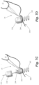
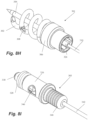
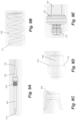
- FIGS 8A-8I depict various views of an anchor assembly for anchoring a suture as an artificial chordae in a heart wall of a patient and Figures 9A-9H depict the various components thereof.
- Anchor assembly includes an anchor delivery assembly 301 and suture lock assembly 303. Once the anchor delivery assembly 301 is used to embed the anchor in the heart wall, the anchor delivery assembly 301 is withdrawn and the suture lock assembly 303 is used to deliver and lock the sutures to the anchor.
- Anchor delivery assembly 301 includes an anchor coil 302 with a central stabilization needle 304 in some embodiments extending longitudinally through the anchor coil 302.
- Stabilization needle 304 provides stability against the ventricular wall during anchor deployment and also provides the attachment to the tether 310 that extends out of the body and is used to rotate the anchor assembly.
- Needle 304 includes a sharpened distal tip 314 configured to penetrate the heart tissue and a threaded portion 316 that releasably secures the needle 304 within internal threads in the anchor hub 306.
- Anchor coil 302 connects to anchor hub 306, such as, for example, by welding, and can include an anti-backout feature.
- Anti-backout feature can be configured as a barb 308 positioned around coil 302 that keeps the coil 302 from rotating back out of the tissue due to the natural rhythm of the heart.
- barb 308 can be welded onto the coil 302.
- Coil 302 includes a sharpened distal tip 312 configured to penetrate the tissue in the heart.
- anchor assembly 300 can be provided without stabilizing needle 304.
- a stabilizing needle can alternatively be provided with an anchor delivery catheter, as described below with respect to Figures 15A-15H .
- anchor hub 306 includes internal threading in a distal portion of anchor hub to releasably secure needle 304 therein.
- Anchor hub 306 also provides a proximally facing suture clamping surface 318 extending around anchor hub 306.
- Anchor driver 320 includes a drive end 322 that mates with corresponding internal geometry in the proximal portion of anchor hub 306 to enable rotation of anchor hub 306 with anchor driver 320.
- Anchor driver 320 can further includes a helical hollow strand (HHS) 324 that extends out of the body and is twisted to provide the torque necessary to drive the anchor coil 302 into the tissue.
- HHS helical hollow strand
- tether 310 extends through anchor driver HHS 324 and anchor driver 320 to a connection within anchor hub 306 to an aperture in the proximal end of stabilizing needle 304.
- a stiffening tube 326 can be threaded over tether 310 within anchor hub 306 to stiffen a small portion of the tether 310 to provide better alignment to component that need to mate within the anchor hub 306.
- the tether 310 can attach to the anchor hub 306.
- Suture lock assembly 303 includes a suture lock configured as a spring 328 that locks the suture by compressing the suture against the suture capture surface 318 of the anchor hub 306.
- Suture lock spring 328 can be delivered to the anchor on a spring carrier 330.
- Spring carrier 330 can include a pair of upwardly raised ledges 348 defining a suture channel 344 therebetween.
- Each ledge 348 can include a lock depression 350 in which suture lock spring 328 is seated for delivery and a retention lip 352 projecting upwardly from lock depression 350 to prevent inadvertent dislodgement of suture lock spring 328.
- Spring carrier 330 includes a distal portion 332 that mates with the anchor hub 306 to provide a tensioning point that is near the final point of suture lock to ensure proper tension is maintained.
- Tubing 334 extends from spring carrier 330 back out of the body to provide a hollow pathway for the tether 310 to enable advancement of the spring carrier 330 guided to the anchor hub 306.
- tubing 334 can be comprised of PEEK and can be bonded to the spring carrier.
- a pusher 336 can be advanced over tubing 334 and spring carrier 330 and includes a distal surface 338 configured to engage the suture spring lock 328 to push the suture lock 328 over the retention lips 352 and off of the spring carrier 330, onto the anchor hub 306 and against the suture clamping surface 318 of the anchor hub 306.
- a pusher connector 340 can be employed to connect the pusher to a catheter 342 used to move the suture lock assembly 303.
- suture lock assembly 303 The routing of a suture 30 through suture lock assembly 303 can be seen with respect to Figure 8G .
- the suture 30 extending from the leaflet is threaded through the suture channel 344 of the spring carrier 330 beneath the suture lock spring 328, into the pusher 336 and out a suture aperture 346 in the pusher.
- the suture 30 can then extend back through the anchor catheter out of the body for suture tensioning.
- the suture lock spring 328 When the suture lock spring 328 is deployed with the pusher 336, the suture 30 is crimped under tension between the suture lock spring 328 and the suture capture surface 318 of the anchor base 306.
- FIGS 10A-10J depict schematic representations of various steps of a method of repairing a heart valve with an anchor system including anchor delivery assembly 301 and suture locking assembly 303.
- An anchor delivery catheter 323 delivers the anchor delivery assembly 301 into the heart and the anchor is partially rotated out of the catheter 323 by twisting anchor driver HHS 324 to rotate anchor driver 320 to expose the stabilizing needle 304 to enable insertion of the needle 304 into the heart wall without exposing the anchor coil 302.
- the anchor hub 306 is then further rotated to insert the anchor coil 302 into the heart tissue and the anchor catheter 323 and anchor driver 320 withdrawn as depicted in Figures 10D-10E , leaving a tether 310 in place extending from an anchor hub 306 back out of the heart.
- Suture lock delivery system 303 is then loaded into anchor catheter 323 and threaded over tether 310 to bring one or more sutures to the anchor as depicted in Figures 10F-10J .
- the suture locking assembly 303 is then primarily withdrawn, leaving the spring carrier 330 that holds a locking spring 328 attached to anchor hub 806 as depicted in Figure 10G .
- the sutures 30 can then be appropriately tensioned and then the suture lock delivery system 303 brought back to the anchor as depicted in Figure 10H with pusher 336 deploying the locking spring 328 off of the spring carrier 330 and onto the anchor hub 306 to clamp the sutures 30 between the locking spring 328 and the anchor hub 306 at the adjusted tension.
- the suture lock delivery system 303 can then be removed, followed by removal of the tether 310 and attached stabilizing needle 804 and the sutures 30 cut to complete the procedure.
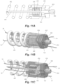
- FIGS 11A-11C depict various views of an anchor assembly 400 for anchoring a suture as an artificial chordae in a heart wall of a patient and Figures 12A-12F depict the various components thereof.
- anchor assembly 400 includes an anchor coil 402 and, in some embodiments, a stabilizing needle 404 as well as a suture lock configured as a locking spring 428 for locking the sutures at an adjusted tension.
- Anchor coil 402 includes a sharpened distal tip 412 for penetrating tissue and, in some embodiments, can be include anti-backout features as described herein.
- Anchor coil 402 can be attached to anchor hub 406, such as, for example, by laser welding.
- the proximal portion of anchor hub 406 can comprise a drive end 414 having, e.g., a hex geometry for mating with an anchor driver such as those disclosed above.
- a suture aperture 416 can be disposed in a distal end of anchor hub 406 to enable a suture to pass from coil 402 through anchor hub 406.
- Anchor hub 406 can further define an internal piston opening 418 matching an outer diameter of a piston chamber 408 and that enables the piston chamber to slide distally and proximally within the piston opening 418.
- Suture locking spring 428 can be disposed between the distal end of anchor hub 406 and a proximal end of piston chamber 408 to bias the piston chamber 408 proximally.
- the piston chamber 408 includes a distally facing spring opening 420 (see Figure 11A ) that constrains the spring 428 and enables the spring 428 expand and contract as piston chamber 408 moves proximally and distally.
- Piston chamber 408 can further include a central needle opening 422 and a pair of suture openings 424 that enable passage of the needle 404 and one or more sutures therethrough, respectively.
- An end cap 410 can be connected to anchor hub 406 such as, for example, by welding after the piston chamber 408 and spring 428 are loaded into the anchor hub 406.
- the outer geometry 410 of the end cap can include a matching, e.g., hex geometry to the anchor hub 406.
- End cap 410 can also include a pair of suture openings 426 to enable ends of a suture to pass through the end cap 410.
- a needle opening 430 through end cap 410 can be threaded to receive a threaded portion 432 of the needle 404. Needle shaft 434 and needle shoulder 436 can be inserted through the needle opening 430 of end cap 410 to enable threaded portion 432 of needle 404 to be screwed into needle opening 430.
- a tether (not pictured) such as those described herein can be secured within tether aperture 440 in needle cap 438 and twisted to provide the torque necessary to turn the needle 404, with needle cap 438 further preventing the needle 404 from being screwed distally through needle opening 430 of end cap 410.
- Needle shaft 434 can fit through needle opening 422 in piston chamber 408, but needle shoulder 436 cannot, such that needle shoulder 436 abuts piston chamber 408, such that distal movement of needle 404 presses down on piston chamber 408 to move the chamber distally and compresses the spring 428. Conversely, proximal movement of needle 404 releases the pressure on the piston chamber 408 enabling the spring 428 to move the chamber 408 proximally within the anchor hub 406.
- anchor assembly 400 can be provided without stabilizing needle 404.
- a stabilizing needle can alternatively be provided with an anchor delivery catheter, as described below with respect to Figures 15A-15H .
- the tether can be connected to components similar to the needle cap 438, threaded portion 432, and needle shoulder 436 (without the needle shaft 434) to control movement of the end cap 410.
- FIGS 11A-11B depict the manner in which a suture 30 is routed through anchor assembly 30.
- the suture is threaded through the anchor assembly outside of the body by passing the suture ends through the coil 402 and suture aperture 416 of the anchor hub 406 and then separately through the suture openings 424 of the piston chamber 408 and the suture openings 426 of the end cap 410 such that the suture ends extend back through the anchor catheter out of the body to enabling suture tensioning.
- the needle shoulder 436 pushing on the piston chamber 408 to compress the spring 428 causes the suture 30 to be able to slide freely for tensioning.
- the needle can be moved back proximally to release the pressure on the spring 428 and move the piston chamber 408 upward to lock the suture by crimping the suture between the piston chamber 408 and the end cap 410.
- the suture openings 424 is the piston chamber 408 are not longitudinally aligned with the suture openings 426 in the end cap 410, which enables the suture to be crimped between the piston chamber 408 and the end cap 410 when the two components are abutting one another under the force of the spring.
- Anchor assembly 500 includes an anchor coil 502 that embeds the anchor assembly 500 into heart tissue.
- Anchor coil 502 includes a sharpened distal tip 522 to enable the coil to penetrate the tissue.
- Anchor coil 502 can also include an anti-backout feature such as a barb 504 that prevents the motion of the heart from twisting the anchor coil 502 out of the tissue.
- barb 504 can be welded onto the coil 502.
- Anchor assembly 500 can also include an anchor hub 506 that can be connected to anchor coil 502, such as, for example, by welding.
- Anchor hub 506 includes a drive end 524 having a shape, e.g., hexagonal, to mate with an anchor driver 516.
- Anchor hub 506 can also include a hollow hub chamber 526 within which a suture locking spring 528 and suture clamp plate 510 are contained.
- An end cap 514 can attach to the proximal end of the anchor hub 506 and can include internal threading 534 that can rotatably receive a threaded tether crimp 512 having a hollow interior portion configured to receive a tether 530 that can be torqued to rotate the tether crimp 512.
- End cap 514 can further include a proximal drive end 535 configured to mate with the anchor driver 516.
- the suture clamp plate 510 can include a pair of suture windows 536 that enable the pair of free ends of the suture 30 to pass through the suture clamp plate 510 (one suture end through each window).
- the distal surface of the suture clamp plate 510 interfaces with the proximal end of the suture locking spring 528 and the proximal surface of the suture clamp plate (between the suture windows 536) interfaces with a drive end 538 of the tether crimp 512.
- the end cap 514 can also include a pair of suture windows 540.
- the suture windows 536 of the suture clamp plate can be offset about 90 degrees from the suture windows 540 of end cap 514.
- Figures 13A-13B appear to show only a single strand of suture 30, typically a pair of free ends of a suture 30 extending from a leaflet will extend through anchor assembly 500.
- the free ends of the suture 30 are threaded through the anchor coil 502, into the anchor hub 506 and through the suture locking spring 528, through the suture windows 536, 540 of the suture clamp plate 510 and the end cap 514 and the through the hollow interior of the driver hypotube 518 out of the body.
- the force of the tether crimp 512 on the suture clamp plate 510 compressing the suture locking spring 528 is released, which causes the spring 528 to expand to push the suture clamp plate 510 against end cap 514 to compress the suture 30 across a tortuous path defined by the offset suture locking windows 536, 540 of the suture clamp plate 510 and the end cap 514.
- the suture 30 is then locked in place at a set tension with respect to the leaflet.
- the natural force of the spring provides the clamping force rather than providing by a component that requires a rotational torque force to clamp the suture.
- an anchor cap 532 to can be advanced over the tether 530 along a cap aperture 548 to anchor hub 506.
- the end cap 514 can include a conical or otherwise tapered proximal end 550 to aid in guiding the anchor cap 532 onto the anchor.
- Anchor cap 532 can further include an internal retention ring 544 having a plurality of retention projections 546 configured to snap onto anchor hub 506 to hold the anchor cap 532 in place on the anchor hub 532.
- the retention projections 546 can be flexible to be flexed across a circumferential retention lip 554 on anchor hub 506 at the distal and of a tapered region and snap into a circumferential retention recess 556 to hold the anchor cap 532 on the anchor hub 506 via interference between the retention projections 546 and the retention lip 554.
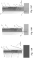
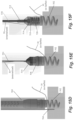
- FIGS 15A-15H depict schematic representations of various steps of a method of repairing a heart valve according to an embodiment that utilizes anchor system 500.
- Anchor catheter 560 can then be used to deliver the anchor system 500 to the heart wall.
- the anchor catheter 560 can include a stabilizing needle 564 extendable from a hollow channel 562 or a lumen within anchor catheter.
- a stabilizing needle 564 can remain within the channel 562 as depicted in Figure 15A .
- the stabilizing needle 564 can be actuated to extend distally of the catheter 560 to penetrate the heart tissue to stabilize the anchor assembly 500 within the anchor catheter 560 when the anchor assembly is subsequently rotated.
- a stabilizing needle provided as part of the anchor catheter could be used with any of the embodiments described herein or a stabilizing needle may not be used with any of those embodiments.
- the anchor catheter 560 can be advanced to contact the heart wall with the stabilizing needle 564 embedded in the wall and the anchor coil 502 rotated via the anchor driver 516 and driver hypotube 518 as described above.
- the anchor catheter 560 and stabilizing needle 564 can then be withdrawn.
- the anchor driver 516 can be disengaged from the anchor assembly 500 and the anchor driver 516 and driver hypotube 518 withdrawn.
- the tether 530 is actuated to unscrew the tether crimp 512 which, as described above, releases the distal pressure on the suture locking spring 528 to enable the spring 528 to expand to compress the suture ends 30 between the suture clamp plate 510 and the end cap 514.
- the anchor cap 532 can then be advanced along the tether530 to the anchor assembly and interfaced with the anchor hub 506.
- the tether 530 and tether crimp 512 can then be removed and the excess suture extending up from the anchor assembly and out of the anchor cap 532 can be cut.
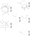
- Anchor assembly 500A depicts an anchor assembly 500A that is similar to anchor assembly 500.
- Anchor assembly 500A also includes an anchor coil 502A with a sharpened distal tip 522A that embeds the anchor assembly 500 into heart tissue and can also include an anti-backout feature such as a barb 504B that prevents the motion of the heart from twisting the anchor coil 502 out of the tissue.
- Anchor assembly 500A can also include an anchor hub 506A that can contain a suture locking spring 528A and suture clamp plate 510A.
- the proximal end of the anchor hub 506A is unitarily formed with the anchor body and an end cap 514A is positioned at a distal end of the anchor hub 506A to retain the suture locking spring 528A and suture clamp plate 510A within the anchor hub 506A.
- Proximal end of anchor hub 506A can include a proximal drive end 535A configured to mate with an anchor driver.
- anchor assembly 500A would also include a tether crimp such as tether crimp 512 of anchor assembly 500 (as shown, for example, in FIG. 15F and 15G ) extending through threaded opening 534A in anchor hub 506A.
- the anchor hub 506A further includes a helical slot 507A extending around anchor body and the suture clamp plate 510A can include a pair of corresponding outwardly projecting tabs 511A configured to interface with slot 507A.
- the suture clamp plate 510A moves along the helical slot 507A, the suture clamp plate 510 rotates within the anchor hub 506A.
- Suture clamp plate 510A can further include a suture window 536A and the proximal end of the anchor hub 506A can also include a suture window 540A.
- Suture clamp plate 510A when the suture clamp plate 510A is initially inserted into the anchor hub 506A by inserting the tabs 511A into the helical slot 507A, the suture windows 536A, 540 of the two components can be aligned with each other.
- Suture clamp plate 510A can also include an opening 537A that enables the plate to be held with a forceps for proper positioning within anchor hub 506A as described herein during assembly.
- the free ends of the suture(s) are threaded through the anchor coil 502A of anchor assembly 500A, through the end cap 514A into the anchor hub 506A and through the suture locking spring 528A, through the aligned suture windows 536A, 540A of the suture clamp plate 510A the anchor hub 506A and out of the body.
- the suture clamp plate 510A can be distally positioned with the tether crimp (not pictured) to compress the suture locking spring 528A to create open space between the suture clamp plate 510A and the proximal end of the anchor hub 506A.
- the suture can be crimped under tension as described above by unscrewing the tether crimp proximally to release the compression on the suture locking spring 528A to cause the spring 528A to expand to push the suture clamp plate 510A against the proximal end of the suture hub 506A.
- the suture clamp plate 510A moves upward, the projecting tabs 511A in helical slot 507A cause the suture clamp plate 510A to rotate within the anchor hub 506A.
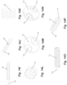
- Figures 17A-17B depict a coil 602 and a barb 604 for an anchor assembly that can be used with embodiments described herein.
- barb 604 is positioned approximately 3 ⁇ 4 to 1 revolution of the coil 602 from the tip 622 of the coil.
- Barb 604 is further sized such that it does not protrude beyond the outer diameter of coil 602 so that it does not interfere with insertion of the coil 602 into the heart tissue.
- the barb 604 is positioned at an angle relative to the angle of coil 602.
- the barb 604 is positioned at an angle of 30 degrees, plus or minus 5 degrees, relative to the coil 602. While a body portion of the barb 604 is welded to the coil to be smooth and free of any burrs or sharp edges, the prong of the barb 604 that extends at an angle from the coil 602 is not welded to the coil.
- the anchor assemblies described herein generally each include one or more of an anchor body, anchor hub, anchor cap, dome etc.
- such components may be comprised of a rigid material such as, for example, stainless steel.
- any such components or combination of components may be provided with a thin cover or jacket over the component or a portion thereof.
- the cover or jacket can be comprised of a polymer material, such as, for example, ePTFE.
- the cover or jacket can have a length greater than the components it is covering such that the polymer or other material extends beyond the components to create a compressible "skirt" to provide additional anchor coverage and/or softening of the tissue interface at the point of contact with the anchor.
- anchor coils are larger in diameter and length and require a greater number of turns that known anchor coils used to anchor other devices such as pacing leads in the heart. This is because unlike pacing leads, anchor coils that serve to anchor sutures as artificial chordae are under immediate and constant forces from the moving valve leaflets that could potentially pull the anchors back out of the heart wall. As such, a more robust fixation provided by a larger and/or longer coil may be desirable to more reliably embed the anchor in the heart wall.
- the coil can be inserted generally perpendicularly to the interior surface of the heart wall. In other embodiments, due to the interior geometry of the hard the coil may be inserted at a non-perpendicular angle to the heart wall.
- the sharpened distal end of the coil and the sharpened distal end of the stabilizing needle can be oriented generally orthogonal to each other.
- anchors can be interchangeably employed in each of the above-described systems.
- Such anchors can include those disclosed in U.S. Patent Application Publication Nos. 2019/0343626 ; 2019/0343633 ; 2019/0343634 ; and 2020/0330228 .
Landscapes
- Health & Medical Sciences (AREA)
- Cardiology (AREA)
- Life Sciences & Earth Sciences (AREA)
- General Health & Medical Sciences (AREA)
- Public Health (AREA)
- Biomedical Technology (AREA)
- Heart & Thoracic Surgery (AREA)
- Veterinary Medicine (AREA)
- Engineering & Computer Science (AREA)
- Animal Behavior & Ethology (AREA)
- Transplantation (AREA)
- Oral & Maxillofacial Surgery (AREA)
- Vascular Medicine (AREA)
- Surgery (AREA)
- Rheumatology (AREA)
- Nuclear Medicine, Radiotherapy & Molecular Imaging (AREA)
- Medical Informatics (AREA)
- Molecular Biology (AREA)
- Prostheses (AREA)
- Surgical Instruments (AREA)
Description
- The present application claims the benefit of
U.S. Provisional Application No. 62/962,054 filed January 16, 2020 U.S. Provisional Application No. 62/987,140 filed March 9, 2020 - The present invention relates to minimally invasive delivery of a suture into the heart. More particularly, the disclosed embodiments relate to inserting and anchoring one or more sutures as artificial chordae tendineae for a flailing or prolapsing leaflet in a beating heart.
- The mitral and tricuspid valves inside the human heart include an orifice (annulus), two (for the mitral) or three (for the tricuspid) leaflets and a subvalvular apparatus. The subvalvular apparatus includes multiple chordae tendineae, which connect the mobile valve leaflets to muscular structures (papillary muscles) inside the ventricles. Rupture or elongation of the chordae tendineae results in partial or generalized leaflet prolapse, which causes mitral (or tricuspid) valve regurgitation. A commonly used technique to surgically correct mitral valve regurgitation is the implantation of artificial chordae (usually 4-0 or 5-0 Gore-Tex sutures) between the prolapsing segment of the valve and the papillary muscle.
- This technique for implantation of artificial chordae was traditionally done by an open heart operation generally carried out through a median sternotomy and requiring cardiopulmonary bypass with aortic cross-clamp and cardioplegic arrest of the heart. Using such open heart techniques, the large opening provided by a median sternotomy or right thoracotomy enables the surgeon to see the mitral valve directly through the left atriotomy, and to position his or her hands within the thoracic cavity in close proximity to the exterior of the heart for manipulation of surgical instruments, removal of excised tissue, and/or introduction of an artificial chordae through the atriotomy for attachment within the heart. However, these invasive open heart procedures in which the heart is stopped beating produce a high degree of trauma, a significant risk of complications, an extended hospital stay, and a painful recovery period for the patient. Moreover, while heart valve surgery produces beneficial results for many patients, numerous others who might benefit from such surgery are unable or unwilling to undergo the trauma and risks of such open heart techniques.
- Techniques for minimally invasive thoracoscopic repair of heart valves while the heart is still beating have also been developed.
U.S. Patent No. 8,465,500 to Speziali discloses a thoracoscopic heart valve repair method and apparatus. Instead of requiring open heart surgery on a stopped heart, the thoracoscopic heart valve repair methods and apparatus taught by Speziali utilize fiber optic technology in conjunction with transesophageal echocardiography (TEE) as a visualization technique during a minimally invasive surgical procedure that can be utilized on a beating heart. More recent versions of these techniques are disclosed inU.S. Patent Nos. 8,758,393 and9,192,374 - Some systems have therefore been proposed that utilize a catheter routed through the patient's vasculature to enter the heart and attach a suture to a heart valve leaflet as an artificial chordae. While generally less invasive than the approaches discussed above, transcatheter heart valve repair can provide additional challenges. For example, with all artificial chordae replacement procedures, in addition to inserting a suture through a leaflet, the suture must also be anchored at a second location, such as at a papillary muscle in the heart, with a suture length, and tension and positioning of the suture should be adjustable to enable the valve to function naturally. If the suture is too short and/or has too much tension, the valve leaflets may not properly close. Conversely, if the suture is too long and/or does not have enough tension, the valve leaflets may still be subject to prolapse. Proper and secure anchoring of the suture at the second position away from the leaflet is therefore a critical aspect of any heart valve repair procedure for inserting an artificial chordae. In the case of transcatheter procedures, such anchoring can be difficult because it can be difficult for the flexible catheter required for routing through the patient's vasculature to apply sufficient force to stably insert traditional suture anchors into the heart wall, e.g., the myocardium.
US2018/064535A1 relates to techniques for tightening tethers of percutaneous implants transluminally, in order to enable percutaneous treatment of functional tricuspid and/or mitral regurgitation.US2010/161041A1 relates to a method, including implanting, at an intraventricular site of a ventricle of a patient, a spool coupled to a first end portion of a longitudinal member, and coupling a second end portion of the longitudinal member to a portion of tissue facing a lumen of the ventricle. - The invention is defined in the appended claims. Disclosed herein are various embodiments of cardiac anchors configured to be inserted into a heart wall of a patient to anchor a suture as an artificial chordae under an appropriate tension for proper valve function. Such cardiac anchors are particularly suitable for use in intravascular, transcatheter procedures.
- In an embodiment, an anchor assembly is configured to implant a cardiac anchor into a heart wall of a patient to anchor a suture configured to extend from a valve leaflet of the heart as an artificial chordae. The anchor assembly can include an anchor hub defining an open interior and a helical coil extending distally from the anchor hub and having a sharpened tip configured to embed the helical coil into the heart wall upon rotation of the helical coil. A spring can be disposed within the open interior of the anchor hub. Compressing the spring distally can create an open space within the open interior of the anchor hub for a suture extending through the anchor hub to slide freely and releasing compression on the spring can cause the spring to expand in a proximal direction to clamp the suture within the open interior of the anchor hub.
- In an embodiment, an anchor assembly is configured to implant a cardiac anchor into a heart wall of a patient to anchor a suture configured to extend from a valve leaflet of the heart as an artificial chordae. Anchor assembly can include an anchor base and a helical coil extending distally from the anchor base and having a sharpened tip configured to embed the helical coil into the heart wall upon rotation of the helical coil. In some embodiments, a stabilizing needle can extend longitudinally through and distally beyond the helical coil and have a sharpened tip configured to pierce the heart wall to stabilize the helical coil for insertion of the helical coil into the heart wall. A suture clamp can be configured to be rotated to clamp a suture under tension between the suture clamp and the anchor base. In embodiments, the suture clamp can include an anchor washer movable along a body of the anchor base and configured to have a suture inserted through a space between the anchor washer and the body of the anchor base and an anchor clamp nut threadedly attached to the anchor base. Rotation of the anchor clamp nut in a first direction can move the anchor clamp nut distally to clamp a suture inserted through the space between the anchor washer and the body of the anchor base between the anchor base and the anchor washer and between the anchor clamp nut and the anchor washer.
- In an embodiment, an anchor assembly is configured to implant a cardiac anchor into a heart wall of a patient to anchor a suture configured to extend from a valve leaflet of the heart as an artificial chordae. The anchor assembly can include a suture anchor including an anchor hub, a helical coil extending distally from the anchor hub and having a sharpened tip configured to embed the helical coil into the heart wall upon rotation of the helical coil, and a suture lock threadedly attached to a proximal end of the anchor hub. The assembly can include an anchor hub driver having a drive end configured to mate with the anchor hub and an anchor hub driver tube configured to be rotated to rotate the suture anchor for insertion into the heart wall. The assembly can further include a suture lock driver having a drive end configured to mate with the suture lock and a suture lock driver tube, such that rotation of the suture lock driver in a first direction moves the suture lock distally to clamp a suture between the suture lock and the anchor hub. In embodiments, the suture lock can include a suture locking wedge including a threaded distal portion configured to interface with a threaded distal portion of the anchor hub and a tapered clamping surface configured to clamp the suture between a chamfered interior surface of the anchor hub and the tapered clamping surface of the suture locking wedge.
- In an embodiment, an anchor assembly is configured to implant a cardiac anchor into a heart wall of a patient to anchor a suture configured to extend from a valve leaflet of the heart as an artificial chordae. The anchor assembly can include a suture anchor including an anchor hub, a helical coil extending distally from the anchor hub and having a sharpened tip configured to embed the helical coil into the heart wall upon rotation of the helical coil. In some embodiments, a stabilizing needle extending longitudinally through and distally beyond the helical coil has a sharpened tip configured to pierce the heart wall to stabilize the helical coil for insertion of the helical coil into the heart wall. An anchor delivery assembly can include an anchor driver configured to mate with the anchor hub to rotate the suture anchor for insertion into the heart wall. A suture lock delivery system can include a lock carrier configured to mate with the anchor hub and to carry a suture lock and a pusher movable with respect to the lock carrier. The pusher can be configured to push the suture lock off of the lock carrier and onto the anchor hub to clamp a suture between the suture lock and the anchor hub. In embodiments, the suture lock is configured as a spring.
- In an embodiment, an anchor assembly is configured to implant a cardiac anchor into a heart wall of a patient to anchor a suture configured to extend from a valve leaflet of the heart as an artificial chordae. The anchor assembly can include an anchor hub defining an open interior and a proximal end cap covering the open interior. A helical coil can extend distally from the anchor base and have a sharpened tip configured to embed the helical coil into the heart wall upon rotation of the helical coil. In some embodiments, a stabilizing needle can extend longitudinally through and distally beyond the anchor hub and the helical coil. The stabilizing needle can have a sharpened tip configured to pierce the heart wall to stabilize the helical coil for insertion of the helical coil into the heart wall and a threaded proximal portion rotatingly attached to the end cap of the anchor hub. A piston chamber can be disposed within the open interior of the anchor hub, with the piston chamber and the end cap each having one or more openings enabling one or more sutures to pass through the piston chamber and the end cap. A spring can be disposed within the piston chamber between a proximal end of the piston chamber and a distal end of the anchor hub such that the spring biases the piston chamber proximally towards the end cap. Rotation of the stabilizing needle in a first direction can move the piston chamber distally to compress the spring to provide space between the piston chamber and the end cap for a suture to move freely and rotation of the stabilizing needle in a second direction can move the piston chamber proximally to clamp the suture between the piston chamber and the end cap.
- The above summary is not intended to describe each illustrated embodiment or every implementation of the subject matter hereof. The figures and the detailed description that follow more particularly exemplify various embodiments.
- Subject matter hereof may be more completely understood in consideration of the following detailed description of various embodiments in connection with the accompanying figures, in which:
-
FIGS. 1 is a schematic representation of a method for inserting a leaflet capture catheter into a beating heart of a patient according to an embodiment. -
FIGS. 2A-2F depict various views of an anchor system for an artificial chordae according to an embodiment. -
FIGS. 3A-3L depict the various components of the anchor system ofFigures 2A-2F . -
FIGS 4A-4C schematically depict a procedure for anchoring an artificial chordae according to an embodiment. -
FIGS. 5A-5C depict various views of an anchor system for an artificial chordae according to an embodiment. -
FIGS. 6A-6J depict the various components of the anchor system ofFigures 5A-5C . -
FIGS 7A-7D schematically depict a procedure for anchoring an artificial chordae according to an embodiment. -
FIGS. 8A-8I depict various views of an anchor system for an artificial chordae according to an embodiment. -
FIGS. 9A-9H depict the various components of the anchor system ofFigures 8A-8G . -
FIGS 10A-10J schematically depict a procedure for anchoring an artificial chordae according to an embodiment. -
FIGS. 11A-11C depict various views of an anchor system for an artificial chordae according to an embodiment. -
FIGS. 12A-12F depict the various components of the anchor system ofFigures 11A-11C . -
FIGS. 13A-13B depict various view of an anchor system for an artificial chordae according to an embodiment. -
FIGS. 14A-14V depict the various components of the anchor system ofFigures 13A-13B . -
FIGS. 15A-15H schematically depict a procedure for anchoring an artificial chordae according to an embodiment. -
FIGS. 16A-16E depict various views of an anchor system for an artificial chordae according to an embodiment. -
FIGS. 17A-17B depict components of an anchor system for an artificial chordae in an embodiment. - While various embodiments are amenable to various modifications and alternative forms, specifics thereof have been shown by way of example in the drawings and will be described in detail. It should be understood, however, that the intention is not to limit the claimed inventions to the particular embodiments described.
- The present disclosure is generally directed to inserting and anchoring one or more sutures as artificial chordae into one or more heart valve leaflets through an intravascular, transcatheter approach. A heart valve leaflet may be captured and a suture inserted through the leaflet in any manner known in the art. Examples of such leaflet capture catheters are disclosed in copending
U.S. Patent Publication No. 2019/0290260 andU.S. Patent Application No. 16/564,887 . Other transcatheter procedures for inserting an artificial chordae are disclosed inU.S. Patent Publication No. 2016/0143737 andU.S. Patent Application No. 16/745,074 . - In each of the below described embodiments, access into the heart to the valve being repaired can be gained through an intravascular, transcatheter approach. If the valve being repaired is the mitral valve, the valve may further be accessed transseptally.
Figure 1 depicts a schematic representation of an embodiment of an access approach for a heart valve repair system accessing themitral valve 10.Figure 1 depicts aguide catheter 14 accessing the interior of the heart via the femoral vein. In some embodiments, such a system can further include an outer guide catheter and an inner guide catheter. In such embodiments, the outer guide catheter can be inserted into the femoral vein at the patient's groin and advanced through the femoral vein into theinferior vena cava 19 and then into theright atrium 16. In various embodiments, the outer guide catheter can be steerable in a single plane and can have an outer diameter of about or less than about 30 French, such as, for example 24 French. Theseptum 18 can then be punctured using an appropriate puncture tool and the outer guide catheter advanced into theseptum 18 or through theseptum 18 into theleft atrium 20. The inner guide catheter can then be axially advanced through the outer guide catheter into theleft atrium 20. In some embodiments, the inner guide catheter can have two plans of steerability and can be maneuvered along with and/or beyond the outer guide catheter to establish a stable position superior to themitral valve 10 and to provide a desired trajectory for operation of a leaflet capture catheter to repair the valve. In other embodiments, anchors as described herein may be implanted through other intravascular approaches as well as non-intravascular approaches. -
Figures 2A-2F depict various views of ananchor assembly 100 for anchoring a suture as an artificial chordae in a heart wall of a patient andFigures 3A-3L depict the various components thereof.Anchor assembly 100 includes ananchor coil 100 that embeds theanchor assembly 100 into heart tissue and, in some embodiments, a central stabilizingneedle 104 extending longitudinally through thecoil 102 to stabilize theanchor assembly 100 while thecoil 102 is driven into the tissue. Ananchor base 106 can connected to theanchor coil 102 and the stabilizingneedle 104.Anchor assembly 100 can further include a plurality of suture clamping components, including ananchor washer 108, ananchor clamp ring 110, ananchor clamp nut 112, an anchorclamp nut cap 114, an anchorclamp nut driver 116 and ananchor cap 118, which will be described in more detail below. Ananchor sheath 124 is used to deliver and cover theanchor assembly 100 before it is deployed and the components of theanchor assembly 100 are actuated with ananchor tether 120 and ananchor driver tube 122 as will also be described in more detail below. - Referring to
Figure 3A , stabilizingneedle 104 can include asharp tip 126 capable of piercing the tissue of the heart wall. By piercing the heart wall with stabilizingneedle 104, the anchor assembly is stably held in position to enable theanchor coil 104 to be embedded into the heart wall to anchor the assembly by rotatinganchor assembly 100. A proximal threadedend 128 of the stabilizingneedle 104 can be configured to be to be connected to anchorbase 106. The proximal threadedend 128 can also be drilled out to provide a hollow interior configured to enable thetether 120 to be attached thereto such as, for example, by laser welding. In other embodiments,anchor assembly 100 can be provided without stabilizingneedle 104. In some such embodiments, a stabilizing needle can alternatively be provided with an anchor delivery catheter, as described below with respect toFigures 15A-15H . -
Anchor coil 102 includes adistal tip 130 for piercing the tissue of the heart wall. In embodiments, theanchor coil 102 is configured to be rotated clockwise to screw into the tissue.Anchor coil 102 can further be provided with anti-backout features, such as one or more barbs, that prevent rotation ofanchor coil 102 due to natural heart rhythms from backing the coil out of the tissue. Theanchor coil 102 can be connected to theanchor base 106 such as, for example, by laser welding. - The inside diameter of the
anchor base 106 can be drilled out to create ahollow passage 132 to receive the proximal portion of the stabilizing needle, including an internally and externally threadedportion 134 that internally interfaces with the proximal threadedend 128 of the stabilizingneedle 104. Achamfer surface 136 ofanchor base 106 that is longitudinally angled with respect to the assembly functions as one of the clamping surfaces for clamping the suture. - The
anchor washer 108 is not threaded or welded to any component. Thewasher 108 can float rotationally and axially unconstrained on theshaft 138 of the anchor base.Anchor washer 108 functions to clamp the suture between theanchor base 106 and theanchor clamp ring 110. Theanchor clamp ring 110 is similarly not threaded or welded onto any component and can axially float on theanchor base shaft 138 but is rotationally constrained on theanchor base 106.Anchor clamp ring 110 is prevented from rotating because it interfaces directly with the suture (which does not rotate) but is pushed down by the anchor clamp nut 112 (which rotates while threading down on the anchor base). In embodiments,anchor clamp ring 110 can be prevented from rotating by cutting off the outer threads on two sides of theanchor base 102. Theanchor clamp nut 112 includesinternal threading 140 to rotationally attach theanchor clamp nut 112 to the external threading of threadedportion 134 ofanchor base 106. As theanchor clamp nut 112 is rotated counterclockwise, it moves down along the threading of threadedportion 134 to clamp the suture. The anchorclamp nut cap 114 interfaces with an openproximal end 142 of theanchor clamp nut 112 and can be attached, e.g., by laser welding, after theanchor clamp nut 112 is threaded on to theanchor base 106 to lock theanchor clamp nut 112 on and prevent removal of theanchor clamp nut 112 from theanchor base 106. After the anchorclamp nut cap 114 is attached to theanchor clamp nut 112, theanchor clamp driver 116 can be attached such as by laser welding onto the anchorclamp nut cap 114 with a drive end 146 (e.g., a hex drive) of theanchor clamp driver 116 interfacing with a correspondingly shapedaperture 144 in the anchorclamp nut cap 114. Rotation of theanchor clamp driver 116 therefore rotates theanchor clamp nut 112. Theanchor cap 118 can be attached to theanchor base 106, such as by laser welding, after theanchor washer 108,anchor clamp ring 110 andanchor clamp nut 112 have been assembled withanchor base 106, which locksanchor clamp nut 112 ontoanchor base 106 to eliminate the risk of accidentally threading theanchor clamp nut 112 back off of theanchor base 106. - The
anchor tether 120 can be a flexible, generally cylindrical component that can travel through theanchor driver tube 122 and theanchor base 106 and be attached to the stabilizingneedle 104 by, for example, laser welding. In one embodiment,tether 120 is a Nitinol wire. Theanchor 100 is driven into tissue by twisting theanchor tether 120 clockwise, with the torque being transferred from theanchor tether 120 to the stabilizingneedle 102 and theanchor base 106 to which theanchor coil 102 is attached, thus causing rotation of theanchor coil 102 to embed the coil into tissue. In embodiments that do not utilize a stabilizingneedle 104 as part of the anchor assembly, theanchor tether 120 can attach to and directly rotate theanchor base 106. - The
anchor driver tube 122 is attached to the anchorclamp nut cap 114 such that rotation of theanchor driver tube 122 causes rotation of theanchor clamp nut 112 to move theanchor clamp nut 122 along the threadedportion 134 of theanchor base 106 to clamp the suture between theanchor base 106,anchor washer 108 andanchor clamp ring 110. As can be seen inFigures 2D-2F , thesuture 30 is threaded through theanchor washer 108 and is clamped therein betweenchamfer surface 136 ofanchor base 106 andanchor clamp ring 110. Theanchor sheath 124 covers theanchor coil 102 before theanchor 100 is deployed. Theanchor sheath 124 can include aslit 148 on one side ofanchor sheath 124 that enables the suture to access the anchor locking components and then enter the anchor sheath proximal to the anchor. Following seating of the anchor in the heart wall, theanchor driver tube 122 andanchor cap 118 and then thetether 120 and stabilizingneedle 104 can be withdrawn by twisting the tether counter-clockwise. - Referring to
Figures 2D-2F , the routing ofsuture 30 throughanchor assembly 100 is depicted. Aftersuture 30 is inserted into a valve leaflet,suture 30 is threaded throughanchor washer 108 outside of the body. Theanchor 100 is inserted intoanchor sheath 124 and delivered into the heart such that thesuture 30 extends throughanchor sheath 124 back out of the body to enablesuture 30 tension to be adjusted from outside the body. As theanchor clamp nut 112 is tightened, the suture is clamped between thechamfer surface 136 of anchor base and the distal side ofanchor washer 108 and between theanchor clamp ring 110 and the proximal side ofanchor washer 108 to securely hold thesuture 30 at a desired tension. Although depicted as asingle suture 30, it should be understood that a plurality of sutures could be locked in this manner. -
Figures 4A-4C depict schematic representations of various steps of a method of repairing a heart valve according to another embodiment that utilizesanchor system 100. After thesutures 30 are inserted into theleaflet 13, they can be threaded throughanchor washer 108 ofanchor 100 outside of the body. Theanchor 100 can then be inserted into anchor delivery catheter orsheath 124 and positioned adjacent the heart wall. The stabilizingneedle 104 first pierces the tissue to stabilize the anchor while thecoil 102 is driven into the tissue by rotating theanchor 100 as described above. After the anchor 600 has been inserted, the sutures can be tensioned and then locked by rotating ananchor clamp nut 112 to clamp down on thesutures 30. The stabilizingneedle 104 can then be removed and the sutures ends severed as depicted inFigure 4C . -
Figures 5A-5C depict various views of ananchor assembly 200 for anchoring a suture as an artificial chordae in a heart wall of a patient andFigures 6A-6J depict the various components thereof.Anchor assembly 200 includes ananchor coil 202 configured to embed the anchor into the tissue of the heart wall and a suture locking system that locks one or more sutures at a set tension for proper valve function. -
Anchor coil 202 includes a sharpeneddistal tip 222 configured to pierce the tissue and is configured to be embedded into the heart wall by clockwise rotation and can be used with anti-backout features, such as one or more barbs. Theanchor coil 202 is connected to theanchor hub 204, such as, for example, by laser welding. Theanchor hub 204 includes aproximal drive end 224 such, as for, example a hex drive configured to interface with ananchor hub driver 216 to enable rotation of thehub 204 andcoil 202. As can be seen inFigure 5B , theanchor hub 204 can further include an interior threadedportion 226 at a distal portion of theanchor hub 204 and an interiorchamfered chamber 228 at a proximal portion thereof. - Suture locking
wedge 206 includes a distal threadedportion 230 configured to interface with the interior threadedportion 226 ofanchor hub 204. A taperedouter surface 232 ofsuture locking wedge 206 interfaces with the interiorchamfered chamber 228 of the anchor hub to lock the suture between the two surfaces. A hollowlongitudinal chamber 234 extends from distal threadedportion 230 ofsuture locking wedge 206 and is in communication with across aperture 236 through taperedouter surface 232. As can be seen inFigure 2C , this enables one ormore sutures 30 to extend proximally up throughanchor coil 202, through thehollow chamber 234 and out of thecross apertures 236 of anchor base and back proximally through the device. At the distal end,suture locking wedge 206 can further include adrive end 238, such as a hex drive, to interface with asuture lock driver 212. The center of thedrive end 238 can includeinternal threading 240 to interface with a threadeddistal end 242 oftether crimp 208.Proximal portion 244 of tether crimp includes a drilled out hollow chamber that is crimped onto thetether 210. In an embodiment,tether 210 is a Nitinol wire that is, for example, 0.015 inches in diameter. Thetether crimp 208 andtether 210 are fastened to thesuture locking wedge 206 to ensure that the anchor is not prematurely released. -
Suture lock driver 212 has adrive end 248 with an internal geometry, e.g., hex, matching that of thedrive end 238 of thesuture locking wedge 206. In embodiments, the two components interface with a slip fit.Suture lock driver 212 further includes twoopen sides 250 that enable sutures to entersuture lock driver 212 and exit out of aproximal aperture 252.Suture lock driver 212 is connected to suturelock driver tube 214 such as, for example, by laser welding.Suture lock driver 212 can be rotated clockwise via suturelock driver tube 214 to move thesuture locking wedge 206 distally to clamp thesuture 30 between thesuture locking wedge 206 and theanchor hub 204. In some embodiments, suturelock driver tube 214 can be laser cut atlines 254 to provided added flexibility for maneuvering the device through the vasculature and to reduce torque buildup on the distal portion of the system. -
Anchor hub driver 216 includes adrive end 256 with an internal geometry, e.g., hex, matching that of thedrive end 224 of theanchor hub 204. Rotating of theanchor hub driver 216 via the anchorhub driver tube 218 in a clockwise direction rotates theanchor hub 204 and theanchor coil 202 to embed theanchor coil 202 into the heart tissue. Applying a counter-force on theanchor hub 204 with theanchor hub driver 216 can also provide a counter-torque when applying a final torque to thesuture locking wedge 206 with thesuture lock driver 212 to lock the sutures within theanchor hub 204 with thesuture locking wedge 206. In embodiments, the anchorhub driver tube 218 can also be connected to theanchor hub driver 216 by laser welding and can be laser cut alonglines 258 to provide added flexibility. A coveringdome 220 can be provided to mate with theanchor hub 204 and cover the sutures once the sutures have been tensioned, locked, and cut. In embodiments, the coveringdome 220 can be covered with ePTFE to encourage tissue ingrowth and discourage thrombosis. - Referring to
Figure 5C , the routing ofsutures 30 through anchor system is depicted (in which a pair of sutures is depicted, by fewer or greater sutures could be employed). After eachsuture 30 is deployed into a leaflet, the ends of thesuture 30 are threaded throughanchor system 200 such that they extend back throughanchor coil 202 andanchor hub 204, into thedistal chamber 234 and out of thecross aperture 236 of thesuture locking wedge 206, and back throughsuture lock driver 212, suturelock drive tube 214 and anchorhug drive tube 218 to be able to be tensioned from outside of the body. When thesuture locking wedge 206 is advanced distally, thesutures 30 are clamped between thetapered surface 232 of thesuture locking wedge 206 and thechamfered chamber 228 of theanchor hub 204 to lock the suture at a desired tension. -
Figures 7A-7D depict schematic representations of various steps of a method of repairing a heart valve according to another embodiment that also utilizesanchor system 200. Aftersutures 30 are inserted into theleaflet 13, thesutures 30 can be threaded through theanchor coil 202 and anchor body 704 of anchor exterior to the body.Anchor catheter 223 can then be used to deliver theanchor system 200 to the heart wall. Theanchor hub driver 216 can then be used with the anchorhub driver tube 218 to rotate the anchor to 200 embed thecoil 202 into the heart wall. As thecoil 202 advances, thesuture 30 slides through the coil and to theanchor hub 204 once the coil is full inserted into the tissue. Theanchor hub driver 216 and anchorhub driver tube 218 can then be withdrawn above as depicted inFigure 7B . The sutures can then be preliminarily tensioned and locked by rotatingsuture lock driver 212 clockwise with suturelock driver tube 214 to advance suture locking wedge 206 (seeFigure 7C ) to clamp the suture inanchor hub 204 as described above. In embodiments, if the tension is not appropriate thesuture locking wedge 206 can be unlocked and the sutures retensioned. Once desired tension is achieved and thesuture locking wedge 206 is preliminarily locked, theanchor hub driver 216 can be brought back down to apply a counter torque while applying a strong torque to thesuture locking wedge 206 with thesuture lock driver 212 for final locking. Thesuture lock driver 212 andanchor hub driver 216 can then be withdrawn, leavingtether 210 extending from theanchor 200 back out of the heart. The free ends of thesuture 30 can then be severed and asuture cover 220 can be advanced along thetether 210 to be seated on theanchor hub 204 to coversutures 30. Thetether 210 can then be severed and withdrawn from the body, leaving theanchor 200 in place. -
Figures 8A-8I depict various views of an anchor assembly for anchoring a suture as an artificial chordae in a heart wall of a patient andFigures 9A-9H depict the various components thereof. Anchor assembly includes ananchor delivery assembly 301 andsuture lock assembly 303. Once theanchor delivery assembly 301 is used to embed the anchor in the heart wall, theanchor delivery assembly 301 is withdrawn and thesuture lock assembly 303 is used to deliver and lock the sutures to the anchor. -
Anchor delivery assembly 301 includes ananchor coil 302 with acentral stabilization needle 304 in some embodiments extending longitudinally through theanchor coil 302.Stabilization needle 304 provides stability against the ventricular wall during anchor deployment and also provides the attachment to thetether 310 that extends out of the body and is used to rotate the anchor assembly.Needle 304 includes a sharpeneddistal tip 314 configured to penetrate the heart tissue and a threadedportion 316 that releasably secures theneedle 304 within internal threads in theanchor hub 306.Anchor coil 302 connects to anchorhub 306, such as, for example, by welding, and can include an anti-backout feature. Anti-backout feature can be configured as abarb 308 positioned aroundcoil 302 that keeps thecoil 302 from rotating back out of the tissue due to the natural rhythm of the heart. In embodiments,barb 308 can be welded onto thecoil 302.Coil 302 includes a sharpeneddistal tip 312 configured to penetrate the tissue in the heart. In other embodiments, anchor assembly 300 can be provided without stabilizingneedle 304. In some such embodiments, a stabilizing needle can alternatively be provided with an anchor delivery catheter, as described below with respect toFigures 15A-15H . - As noted above,
anchor hub 306 includes internal threading in a distal portion of anchor hub to releasablysecure needle 304 therein.Anchor hub 306 also provides a proximally facingsuture clamping surface 318 extending aroundanchor hub 306.Anchor driver 320 includes adrive end 322 that mates with corresponding internal geometry in the proximal portion ofanchor hub 306 to enable rotation ofanchor hub 306 withanchor driver 320.Anchor driver 320 can further includes a helical hollow strand (HHS) 324 that extends out of the body and is twisted to provide the torque necessary to drive theanchor coil 302 into the tissue. As can be seen inFigure 8B ,tether 310 extends throughanchor driver HHS 324 andanchor driver 320 to a connection withinanchor hub 306 to an aperture in the proximal end of stabilizingneedle 304. A stiffeningtube 326 can be threaded overtether 310 withinanchor hub 306 to stiffen a small portion of thetether 310 to provide better alignment to component that need to mate within theanchor hub 306. In embodiments that do not utilize a stabilizingneedle 304 as part of the anchor assembly, thetether 310 can attach to theanchor hub 306. -
Suture lock assembly 303 includes a suture lock configured as aspring 328 that locks the suture by compressing the suture against thesuture capture surface 318 of theanchor hub 306.Suture lock spring 328 can be delivered to the anchor on aspring carrier 330.Spring carrier 330 can include a pair of upwardly raisedledges 348 defining asuture channel 344 therebetween. Eachledge 348 can include alock depression 350 in whichsuture lock spring 328 is seated for delivery and aretention lip 352 projecting upwardly fromlock depression 350 to prevent inadvertent dislodgement ofsuture lock spring 328.Spring carrier 330 includes a distal portion 332 that mates with theanchor hub 306 to provide a tensioning point that is near the final point of suture lock to ensure proper tension is maintained.Tubing 334 extends fromspring carrier 330 back out of the body to provide a hollow pathway for thetether 310 to enable advancement of thespring carrier 330 guided to theanchor hub 306. In embodiments,tubing 334 can be comprised of PEEK and can be bonded to the spring carrier. Apusher 336 can be advanced overtubing 334 andspring carrier 330 and includes adistal surface 338 configured to engage thesuture spring lock 328 to push thesuture lock 328 over theretention lips 352 and off of thespring carrier 330, onto theanchor hub 306 and against thesuture clamping surface 318 of theanchor hub 306. Apusher connector 340 can be employed to connect the pusher to acatheter 342 used to move thesuture lock assembly 303. - The routing of a
suture 30 throughsuture lock assembly 303 can be seen with respect toFigure 8G . Outside of the body thesuture 30 extending from the leaflet is threaded through thesuture channel 344 of thespring carrier 330 beneath thesuture lock spring 328, into thepusher 336 and out asuture aperture 346 in the pusher. Thesuture 30 can then extend back through the anchor catheter out of the body for suture tensioning. When thesuture lock spring 328 is deployed with thepusher 336, thesuture 30 is crimped under tension between thesuture lock spring 328 and thesuture capture surface 318 of theanchor base 306. -
Figures 10A-10J depict schematic representations of various steps of a method of repairing a heart valve with an anchor system includinganchor delivery assembly 301 andsuture locking assembly 303. Ananchor delivery catheter 323 delivers theanchor delivery assembly 301 into the heart and the anchor is partially rotated out of thecatheter 323 by twistinganchor driver HHS 324 to rotateanchor driver 320 to expose the stabilizingneedle 304 to enable insertion of theneedle 304 into the heart wall without exposing theanchor coil 302. Theanchor hub 306 is then further rotated to insert theanchor coil 302 into the heart tissue and theanchor catheter 323 andanchor driver 320 withdrawn as depicted inFigures 10D-10E , leaving atether 310 in place extending from ananchor hub 306 back out of the heart. Suturelock delivery system 303 is then loaded intoanchor catheter 323 and threaded overtether 310 to bring one or more sutures to the anchor as depicted inFigures 10F-10J . Thesuture locking assembly 303 is then primarily withdrawn, leaving thespring carrier 330 that holds alocking spring 328 attached to anchor hub 806 as depicted inFigure 10G . Thesutures 30 can then be appropriately tensioned and then the suturelock delivery system 303 brought back to the anchor as depicted inFigure 10H withpusher 336 deploying thelocking spring 328 off of thespring carrier 330 and onto theanchor hub 306 to clamp thesutures 30 between the lockingspring 328 and theanchor hub 306 at the adjusted tension. The suturelock delivery system 303 can then be removed, followed by removal of thetether 310 and attached stabilizing needle 804 and thesutures 30 cut to complete the procedure. -
Figures 11A-11C depict various views of an anchor assembly 400 for anchoring a suture as an artificial chordae in a heart wall of a patient andFigures 12A-12F depict the various components thereof. As with the previous embodiment, anchor assembly 400 includes ananchor coil 402 and, in some embodiments, a stabilizingneedle 404 as well as a suture lock configured as alocking spring 428 for locking the sutures at an adjusted tension. -
Anchor coil 402 includes a sharpeneddistal tip 412 for penetrating tissue and, in some embodiments, can be include anti-backout features as described herein.Anchor coil 402 can be attached to anchorhub 406, such as, for example, by laser welding. The proximal portion ofanchor hub 406 can comprise a drive end 414 having, e.g., a hex geometry for mating with an anchor driver such as those disclosed above. Asuture aperture 416 can be disposed in a distal end ofanchor hub 406 to enable a suture to pass fromcoil 402 throughanchor hub 406.Anchor hub 406 can further define aninternal piston opening 418 matching an outer diameter of apiston chamber 408 and that enables the piston chamber to slide distally and proximally within thepiston opening 418. Suture lockingspring 428 can be disposed between the distal end ofanchor hub 406 and a proximal end ofpiston chamber 408 to bias thepiston chamber 408 proximally. Thepiston chamber 408 includes a distally facing spring opening 420 (seeFigure 11A ) that constrains thespring 428 and enables thespring 428 expand and contract aspiston chamber 408 moves proximally and distally.Piston chamber 408 can further include acentral needle opening 422 and a pair ofsuture openings 424 that enable passage of theneedle 404 and one or more sutures therethrough, respectively. - An
end cap 410 can be connected to anchorhub 406 such as, for example, by welding after thepiston chamber 408 andspring 428 are loaded into theanchor hub 406. Theouter geometry 410 of the end cap can include a matching, e.g., hex geometry to theanchor hub 406.End cap 410 can also include a pair ofsuture openings 426 to enable ends of a suture to pass through theend cap 410. Aneedle opening 430 throughend cap 410 can be threaded to receive a threadedportion 432 of theneedle 404.Needle shaft 434 andneedle shoulder 436 can be inserted through theneedle opening 430 ofend cap 410 to enable threadedportion 432 ofneedle 404 to be screwed intoneedle opening 430. A tether (not pictured) such as those described herein can be secured withintether aperture 440 inneedle cap 438 and twisted to provide the torque necessary to turn theneedle 404, withneedle cap 438 further preventing theneedle 404 from being screwed distally through needle opening 430 ofend cap 410.Needle shaft 434 can fit through needle opening 422 inpiston chamber 408, butneedle shoulder 436 cannot, such thatneedle shoulder 436 abutspiston chamber 408, such that distal movement ofneedle 404 presses down onpiston chamber 408 to move the chamber distally and compresses thespring 428. Conversely, proximal movement ofneedle 404 releases the pressure on thepiston chamber 408 enabling thespring 428 to move thechamber 408 proximally within theanchor hub 406. In other embodiments, anchor assembly 400 can be provided without stabilizingneedle 404. In some such embodiments, a stabilizing needle can alternatively be provided with an anchor delivery catheter, as described below with respect toFigures 15A-15H . In such embodiments, the tether can be connected to components similar to theneedle cap 438, threadedportion 432, and needle shoulder 436 (without the needle shaft 434) to control movement of theend cap 410. -
Figures 11A-11B depict the manner in which asuture 30 is routed throughanchor assembly 30. Following insertion of the suture into the leaflet, the suture is threaded through the anchor assembly outside of the body by passing the suture ends through thecoil 402 andsuture aperture 416 of theanchor hub 406 and then separately through thesuture openings 424 of thepiston chamber 408 and thesuture openings 426 of theend cap 410 such that the suture ends extend back through the anchor catheter out of the body to enabling suture tensioning. As theneedle 404 is moved distally, theneedle shoulder 436 pushing on thepiston chamber 408 to compress thespring 428 causes thesuture 30 to be able to slide freely for tensioning. When proper tension is achieved, the needle can be moved back proximally to release the pressure on thespring 428 and move thepiston chamber 408 upward to lock the suture by crimping the suture between thepiston chamber 408 and theend cap 410. Note that thesuture openings 424 is thepiston chamber 408 are not longitudinally aligned with thesuture openings 426 in theend cap 410, which enables the suture to be crimped between thepiston chamber 408 and theend cap 410 when the two components are abutting one another under the force of the spring. -
Figures 13A-13B depict various views of ananchor assembly 500 for anchoring a suture as an artificial chordae in a heart wall of a patient andFigures 14A-14V depict the various components thereof.Anchor assembly 500 includes ananchor coil 502 that embeds theanchor assembly 500 into heart tissue.Anchor coil 502 includes a sharpeneddistal tip 522 to enable the coil to penetrate the tissue.Anchor coil 502 can also include an anti-backout feature such as abarb 504 that prevents the motion of the heart from twisting theanchor coil 502 out of the tissue. In embodiments,barb 504 can be welded onto thecoil 502. -
Anchor assembly 500 can also include ananchor hub 506 that can be connected to anchorcoil 502, such as, for example, by welding.Anchor hub 506 includes adrive end 524 having a shape, e.g., hexagonal, to mate with ananchor driver 516.Anchor hub 506 can also include ahollow hub chamber 526 within which asuture locking spring 528 andsuture clamp plate 510 are contained. Anend cap 514 can attach to the proximal end of theanchor hub 506 and can includeinternal threading 534 that can rotatably receive a threadedtether crimp 512 having a hollow interior portion configured to receive atether 530 that can be torqued to rotate thetether crimp 512.End cap 514 can further include aproximal drive end 535 configured to mate with theanchor driver 516. - The
suture clamp plate 510 can include a pair ofsuture windows 536 that enable the pair of free ends of thesuture 30 to pass through the suture clamp plate 510 (one suture end through each window). The distal surface of thesuture clamp plate 510 interfaces with the proximal end of thesuture locking spring 528 and the proximal surface of the suture clamp plate (between the suture windows 536) interfaces with adrive end 538 of thetether crimp 512. Theend cap 514 can also include a pair ofsuture windows 540. In embodiments, thesuture windows 536 of the suture clamp plate can be offset about 90 degrees from thesuture windows 540 ofend cap 514. Theanchor driver 516 can have an internal geometry matching that of theanchor hub 506drive end 524 and/or theend cap 514drive end 535 such that rotation of theanchor driver 516 withdriver hypotube 518 extending back to the control handle outside of the body rotates anchor assembly. In embodiments, driver hypotube 518 can be cut, e.g., by laser cutting, with aspecial pattern 542 at a plurality of locations along its length to make the driver hypotube 518 torqueable yet flexible. - It should be noted that although
Figures 13A-13B appear to show only a single strand ofsuture 30, typically a pair of free ends of asuture 30 extending from a leaflet will extend throughanchor assembly 500. Referring primarily toFigure 13B , in operation the free ends of thesuture 30 are threaded through theanchor coil 502, into theanchor hub 506 and through thesuture locking spring 528, through thesuture windows suture clamp plate 510 and theend cap 514 and the through the hollow interior of the driver hypotube 518 out of the body. In the initial configuration, thetether crimp 512 can be in a distally advanced position that drives thesuture clamp plate 510 down to compress thesuture locking spring 528 to createopen space 513 between thesuture clamp plate 510 and theend cap 514 to create a low friction path for thesuture 30 to move generally freely before and during suture tensioning, as depicted inFigure 13B . To crimp thesuture 30 under tension after anchor deployment and suture tensioning, thetether 30 is rotated with the control handle to unscrew thetether crimp 512 and pull thetether crimp 512 proximally through the threading 534 of theend cap 514. As the tether crimp 512moves proximally, the force of thetether crimp 512 on thesuture clamp plate 510 compressing thesuture locking spring 528 is released, which causes thespring 528 to expand to push thesuture clamp plate 510 againstend cap 514 to compress thesuture 30 across a tortuous path defined by the offsetsuture locking windows suture clamp plate 510 and theend cap 514. Thesuture 30 is then locked in place at a set tension with respect to the leaflet. Thus, in this embodiment the natural force of the spring provides the clamping force rather than providing by a component that requires a rotational torque force to clamp the suture. - After the
suture 30 is locked, ananchor cap 532 to can be advanced over thetether 530 along acap aperture 548 toanchor hub 506. Theend cap 514 can include a conical or otherwise taperedproximal end 550 to aid in guiding theanchor cap 532 onto the anchor.Anchor cap 532 can further include aninternal retention ring 544 having a plurality ofretention projections 546 configured to snap ontoanchor hub 506 to hold theanchor cap 532 in place on theanchor hub 532. In embodiments, theretention projections 546 can be flexible to be flexed across a circumferential retention lip 554 onanchor hub 506 at the distal and of a tapered region and snap into acircumferential retention recess 556 to hold theanchor cap 532 on theanchor hub 506 via interference between theretention projections 546 and the retention lip 554. -
Figures 15A-15H depict schematic representations of various steps of a method of repairing a heart valve according to an embodiment that utilizesanchor system 500. Aftersutures 30 are inserted into a leaflet, the free ends of thesuture 30 can be threaded through theanchor assembly 500 as described above exterior to the body such that thesuture 30 extend distally out ofanchor coil 502 to the leaflet.Anchor catheter 560 can then be used to deliver theanchor system 500 to the heart wall. In this embodiment, theanchor catheter 560 can include a stabilizingneedle 564 extendable from ahollow channel 562 or a lumen within anchor catheter. As theanchor catheter 560 is delivered into the heart and near the heart wall, in some embodiments a stabilizingneedle 564 can remain within thechannel 562 as depicted inFigure 15A . When theanchor catheter 560 nears the heart wall, the stabilizingneedle 564 can be actuated to extend distally of thecatheter 560 to penetrate the heart tissue to stabilize theanchor assembly 500 within theanchor catheter 560 when the anchor assembly is subsequently rotated. Although specifically described with respect to the depicted embodiment, such a stabilizing needle provided as part of the anchor catheter could be used with any of the embodiments described herein or a stabilizing needle may not be used with any of those embodiments. - Referring to
Figure 15C , theanchor catheter 560 can be advanced to contact the heart wall with the stabilizingneedle 564 embedded in the wall and theanchor coil 502 rotated via theanchor driver 516 and driver hypotube 518 as described above. Theanchor catheter 560 and stabilizingneedle 564 can then be withdrawn. As depicted inFigure 15E , theanchor driver 516 can be disengaged from theanchor assembly 500 and theanchor driver 516 and driver hypotube 518 withdrawn. After thesuture 30 has been tensioned, thetether 530 is actuated to unscrew thetether crimp 512 which, as described above, releases the distal pressure on thesuture locking spring 528 to enable thespring 528 to expand to compress the suture ends 30 between thesuture clamp plate 510 and theend cap 514. Theanchor cap 532 can then be advanced along the tether530 to the anchor assembly and interfaced with theanchor hub 506. Thetether 530 andtether crimp 512 can then be removed and the excess suture extending up from the anchor assembly and out of theanchor cap 532 can be cut. - Referring to
Figure 15H , thesuture 30 now extends from theanchor assembly 500 to the leaflet as an artificial chordae. Although thesuture 30 is clamped within the anchor assembly by the force of thesuture locking spring 528 thesuture 30 is also captured between theanchor coil 502 and/oranchor hub 506 and the tissue and/or partially embedded within the tissue. As opposed to anchor configurations in which the suture extends out of a more upward portion of the anchor (e.g., out of the top of the end cap 532), this reduces the torque on the anchor from the naturally forces of the leaflet pulling on thesuture 30 because the forces act at the very bottom of the anchor at the level of the tissue. This significantly reduces the potential for an anchor failure causing the artificial chordae to fail. -
Figures 16A-16C depict ananchor assembly 500A that is similar toanchor assembly 500.Anchor assembly 500A also includes ananchor coil 502A with a sharpeneddistal tip 522A that embeds theanchor assembly 500 into heart tissue and can also include an anti-backout feature such as a barb 504B that prevents the motion of the heart from twisting theanchor coil 502 out of the tissue.Anchor assembly 500A can also include ananchor hub 506A that can contain asuture locking spring 528A andsuture clamp plate 510A. In this embodiment, the proximal end of theanchor hub 506A is unitarily formed with the anchor body and anend cap 514A is positioned at a distal end of theanchor hub 506A to retain thesuture locking spring 528A andsuture clamp plate 510A within theanchor hub 506A. Proximal end ofanchor hub 506A can include aproximal drive end 535A configured to mate with an anchor driver. Although not depicted in these figures,anchor assembly 500A would also include a tether crimp such astether crimp 512 of anchor assembly 500 (as shown, for example, inFIG. 15F and15G ) extending through threadedopening 534A inanchor hub 506A. - In this embodiment, the
anchor hub 506A further includes ahelical slot 507A extending around anchor body and thesuture clamp plate 510A can include a pair of corresponding outwardly projectingtabs 511A configured to interface withslot 507A. As will be described in more detail below, as thesuture clamp plate 510A moves along thehelical slot 507A, thesuture clamp plate 510 rotates within theanchor hub 506A.Suture clamp plate 510A can further include asuture window 536A and the proximal end of theanchor hub 506A can also include asuture window 540A. Referring toFigure 16D , when thesuture clamp plate 510A is initially inserted into theanchor hub 506A by inserting thetabs 511A into thehelical slot 507A, thesuture windows Suture clamp plate 510A can also include anopening 537A that enables the plate to be held with a forceps for proper positioning withinanchor hub 506A as described herein during assembly.
Similar to anchorassembly 500, in operation the free ends of the suture(s) are threaded through theanchor coil 502A ofanchor assembly 500A, through theend cap 514A into theanchor hub 506A and through thesuture locking spring 528A, through the alignedsuture windows suture clamp plate 510A theanchor hub 506A and out of the body. In this initial configuration, thesuture clamp plate 510A can be distally positioned with the tether crimp (not pictured) to compress thesuture locking spring 528A to create open space between thesuture clamp plate 510A and the proximal end of theanchor hub 506A. This creates a generally straight, low friction path through the anchor to enable free movement of the suture for suture length adjustment for tensioning of the suture for proper valve function. The suture can be crimped under tension as described above by unscrewing the tether crimp proximally to release the compression on thesuture locking spring 528A to cause thespring 528A to expand to push thesuture clamp plate 510A against the proximal end of thesuture hub 506A. As thesuture clamp plate 510A moves upward, the projectingtabs 511A inhelical slot 507A cause thesuture clamp plate 510A to rotate within theanchor hub 506A. This causes thesuture window 536A in thesuture clamp plate 510A to rotate out of alignment with thesuture window 540A in the proximal end of thesuture hub 506A to enable the suture to be crimped between a solid proximally facing surface of thesuture clamp plate 510A and a solid distally facing surface of the proximal end of theanchor hub 506A. In various embodiments, thesuture window 536A can be rotated approximately, for example, between 50 degrees and 90 degrees offset from thesuture window 540A of thesuture hub 506A when in the locked position. After the suture is locked, theanchor assembly 500A can be capped in a similar manner to anchorassembly 500 described above. -
Figures 17A-17B depict acoil 602 and abarb 604 for an anchor assembly that can be used with embodiments described herein. In the depicted embodiment,barb 604 is positioned approximately ¾ to 1 revolution of thecoil 602 from thetip 622 of the coil.Barb 604 is further sized such that it does not protrude beyond the outer diameter ofcoil 602 so that it does not interfere with insertion of thecoil 602 into the heart tissue. To prevent thecoil 602 from backing out of the heart tissue, thebarb 604 is positioned at an angle relative to the angle ofcoil 602. In the depicted embodiment, thebarb 604 is positioned at an angle of 30 degrees, plus or minus 5 degrees, relative to thecoil 602. While a body portion of thebarb 604 is welded to the coil to be smooth and free of any burrs or sharp edges, the prong of thebarb 604 that extends at an angle from thecoil 602 is not welded to the coil. - The anchor assemblies described herein generally each include one or more of an anchor body, anchor hub, anchor cap, dome etc. In embodiments, such components may be comprised of a rigid material such as, for example, stainless steel. In order to limit wear and abrasion on portions of a suture that may repeatedly contact such components due to natural forces of the heart, any such components or combination of components may be provided with a thin cover or jacket over the component or a portion thereof. In embodiments, the cover or jacket can be comprised of a polymer material, such as, for example, ePTFE. In some embodiments, the cover or jacket can have a length greater than the components it is covering such that the polymer or other material extends beyond the components to create a compressible "skirt" to provide additional anchor coverage and/or softening of the tissue interface at the point of contact with the anchor.
- It should be noted that in some embodiments, anchor coils are larger in diameter and length and require a greater number of turns that known anchor coils used to anchor other devices such as pacing leads in the heart. This is because unlike pacing leads, anchor coils that serve to anchor sutures as artificial chordae are under immediate and constant forces from the moving valve leaflets that could potentially pull the anchors back out of the heart wall. As such, a more robust fixation provided by a larger and/or longer coil may be desirable to more reliably embed the anchor in the heart wall. In some embodiments, the coil can be inserted generally perpendicularly to the interior surface of the heart wall. In other embodiments, due to the interior geometry of the hard the coil may be inserted at a non-perpendicular angle to the heart wall. In addition, in some embodiments the sharpened distal end of the coil and the sharpened distal end of the stabilizing needle can be oriented generally orthogonal to each other.
- Various other anchors can be interchangeably employed in each of the above-described systems. Such anchors can include those disclosed in
U.S. Patent Application Publication Nos. 2019/0343626 ;2019/0343633 ;2019/0343634 ; and2020/0330228 . - Various embodiments of systems, devices, and methods have been described herein. These embodiments are given only by way of example and are not intended to limit the scope of the claimed inventions. It should be appreciated, moreover, that the various features of the embodiments that have been described may be combined in various ways to produce numerous additional embodiments. Moreover, while various materials, dimensions, shapes, configurations and locations, etc. have been described for use with disclosed embodiments, others besides those disclosed may be utilized without exceeding the scope of the claimed inventions.
- Persons of ordinary skill in the relevant arts will recognize that the subject matter hereof may comprise fewer features than illustrated in any individual embodiment described above. The embodiments described herein are not meant to be an exhaustive presentation of the ways in which the various features of the subject matter hereof may be combined. Accordingly, the embodiments are not mutually exclusive combinations of features; rather, the various embodiments can comprise a combination of different individual features selected from different individual embodiments, as understood by persons of ordinary skill in the art. Moreover, elements described with respect to one embodiment can be implemented in other embodiments even when not described in such embodiments unless otherwise noted.
Claims (15)
- An anchor assembly (400; 500; 500A) configured to be implanted into a heart wall of a heart of a patient to anchor a suture that is configured to extend from a valve leaflet of the heart as an artificial chordae, the anchor assembly comprising:an anchor hub (406; 506; 506A) defining an open interior;a helical coil (402; 502; 502A) extending distally from the anchor hub and having a sharpened tip configured to embed the helical coil into the heart wall upon rotation of the helical coil;a spring (428; 528; 528A) disposed within the open interior of the anchor hub selectively configured to be in one of a compressed state or a released state;wherein when the spring is in the compressed state the spring distally creates an open space within the open interior of the anchor hub for the suture to be extended through the anchor hub so as to slide freely within the open interior of the anchor hub, and wherein when the spring is in the released state the spring expands in a proximal direction to clamp the suture across a tortuous path within the open interior of the anchor hub,characterized in that the anchor hub further comprises a proximal end covering the open interior.
- The anchor assembly of claim 1, further comprising a suture clamp plate (510; 510A) disposed and movable within the open interior of the anchor hub.
- The anchor assembly of claim 2, wherein when the spring is in the released state the suture is clamped between the suture clamp plate and the anchor hub.
- The anchor assembly of claim 2 or claim 3, wherein the suture clamp plate is configured to rotate within the open interior relative to the anchor hub as the suture clamp plate moves within the anchor hub.
- The anchor assembly of claim 4, wherein the anchor hub includes a slot (507A) extending around an exterior of the anchor hub and the suture clamp plate includes a pair of projections (511A) configured to interface with the slot to cause the suture clamp plate to rotate as the suture clamp plate moves along the slot.
- The anchor assembly of any of claims 2-5, wherein the anchor hub includes a suture window (540A) and the suture clamp plate includes a suture window (536A) configured to enable the suture to pass therethrough, and wherein when the spring is in the compressed state the suture window of the anchor hub and the suture window of the suture clamp plate are generally aligned with each other and when the spring is in the released state the suture window of the anchor hub is generally offset from the suture window of the suture clamp plate.
- The anchor assembly of any preceding claim, further comprising a tether crimp (512) threadedly received through an opening in the anchor hub.
- The anchor assembly of claim 7, wherein the spring is configured to move from the compressed state to the released state via rotation of the tether crimp.
- The anchor assembly of claim 7 or claim 8, wherein the suture clamp plate is disposed between the spring and the tether crimp.
- The anchor assembly of claim 9, wherein in the compressed state the spring is compressed by the suture clamp plate and the spring is released to the released state by rotation of the tether crimp such that the spring moves the suture clamp plate.
- The anchor assembly of any of claims 7-10, wherein the tether crimp is configured to be rotated from outside the body with a tether extending from the tether crimp, through a vasculature of the patient and out of the patient.
- A heart valve repair system including a guide catheter (14) and the anchor assembly of any of claims 1-11.
- The heart valve repair system of claim 12, further comprising an anchor catheter (560) configured to deliver the anchor assembly to the heart wall.
- The heart valve repair system of claim 13, wherein the anchor catheter is configured to be inserted intravascularly into the patient to deliver the anchor assembly to the heart wall.
- The heart valve repair system of any of claims 12-14, further comprising an anchor driver (516) configured to rotate the anchor assembly.
Priority Applications (1)
| Application Number | Priority Date | Filing Date | Title |
|---|---|---|---|
| EP25180581.8A EP4599800A3 (en) | 2020-01-16 | 2021-01-15 | Helical cardiac anchors for minimally invasive heart valve repair |
Applications Claiming Priority (3)
| Application Number | Priority Date | Filing Date | Title |
|---|---|---|---|
| US202062962054P | 2020-01-16 | 2020-01-16 | |
| US202062987140P | 2020-03-09 | 2020-03-09 | |
| PCT/US2021/070046 WO2021146757A2 (en) | 2020-01-16 | 2021-01-15 | Helical cardiac anchors for minimally invasive heart valve repair |
Related Child Applications (1)
| Application Number | Title | Priority Date | Filing Date |
|---|---|---|---|
| EP25180581.8A Division EP4599800A3 (en) | 2020-01-16 | 2021-01-15 | Helical cardiac anchors for minimally invasive heart valve repair |
Publications (3)
| Publication Number | Publication Date |
|---|---|
| EP4090258A2 EP4090258A2 (en) | 2022-11-23 |
| EP4090258A4 EP4090258A4 (en) | 2024-02-21 |
| EP4090258B1 true EP4090258B1 (en) | 2025-06-25 |
Family
ID=76856607
Family Applications (2)
| Application Number | Title | Priority Date | Filing Date |
|---|---|---|---|
| EP21741951.4A Active EP4090258B1 (en) | 2020-01-16 | 2021-01-15 | Helical cardiac anchors for minimally invasive heart valve repair |
| EP25180581.8A Pending EP4599800A3 (en) | 2020-01-16 | 2021-01-15 | Helical cardiac anchors for minimally invasive heart valve repair |
Family Applications After (1)
| Application Number | Title | Priority Date | Filing Date |
|---|---|---|---|
| EP25180581.8A Pending EP4599800A3 (en) | 2020-01-16 | 2021-01-15 | Helical cardiac anchors for minimally invasive heart valve repair |
Country Status (7)
| Country | Link |
|---|---|
| US (2) | US12208007B2 (en) |
| EP (2) | EP4090258B1 (en) |
| JP (1) | JP7460200B2 (en) |
| CN (1) | CN115243625A (en) |
| AU (1) | AU2021208019B2 (en) |
| CA (1) | CA3165008A1 (en) |
| WO (1) | WO2021146757A2 (en) |
Families Citing this family (15)
| Publication number | Priority date | Publication date | Assignee | Title |
|---|---|---|---|---|
| US11173030B2 (en) | 2018-05-09 | 2021-11-16 | Neochord, Inc. | Suture length adjustment for minimally invasive heart valve repair |
| WO2020214818A1 (en) * | 2019-04-16 | 2020-10-22 | Neochord, Inc. | Transverse helical cardiac anchor for minimally invasive heart valve repair |
| EP4096529B1 (en) * | 2020-03-23 | 2025-05-07 | Edwards Lifesciences Innovation (Israel) Ltd. | Self-locking winch |
| US12419745B2 (en) * | 2020-09-30 | 2025-09-23 | Boston Scientific Scimed, Inc. | Devices, systems, and methods for adjustably tensioning artificial chordae tendineae in a heart |
| EP4221637A4 (en) * | 2020-10-01 | 2024-06-19 | Opus Medical Therapies, LLC | TRANSCATHETER ANCHOR BRACKET AND IMPLANTATION METHODS |
| WO2022159550A1 (en) | 2021-01-21 | 2022-07-28 | Neochord, Inc. | Minimally invasive heart valve repair in a beating heart |
| CN114886612B (en) * | 2022-05-06 | 2024-04-09 | 上海以心医疗器械有限公司 | Wire locking device |
| WO2023220470A1 (en) * | 2022-05-13 | 2023-11-16 | Neochord, Inc. | Suture anchor for minimally invasive heart valve repair |
| CN116019513B (en) * | 2022-12-27 | 2023-10-03 | 南微纽诺医学科技(南京)有限公司 | Suture device |
| CN119055407B (en) * | 2023-05-30 | 2025-11-14 | 杭州德晋医疗科技有限公司 | Cardiac anchors and cardiac anchoring systems |
| CN116549184B (en) * | 2023-07-05 | 2023-09-15 | 科瑞迈吉(北京)医疗科技有限公司 | A nailing device for heart valve repair |
| US20250040919A1 (en) * | 2023-08-01 | 2025-02-06 | Boston Scientific Scimed, Inc. | Drainage devices, systems, and methods |
| CN119632728B (en) * | 2023-09-15 | 2025-09-19 | 杭州德晋医疗科技有限公司 | Anchor assembly |
| CN119632726B (en) * | 2023-09-15 | 2025-09-19 | 杭州德晋医疗科技有限公司 | System for deploying cardiac anchors |
| CN119632727B (en) * | 2023-09-15 | 2025-09-19 | 杭州德晋医疗科技有限公司 | Lock holding device |
Family Cites Families (327)
| Publication number | Priority date | Publication date | Assignee | Title |
|---|---|---|---|---|
| US2751908A (en) | 1953-03-19 | 1956-06-26 | American Cystoscope Makers Inc | Surgical instrument |
| US3664330A (en) | 1969-09-12 | 1972-05-23 | Harold L Deutsch | Fiber optic medical tool |
| US3667474A (en) | 1970-01-05 | 1972-06-06 | Konstantin Vasilievich Lapkin | Dilator for performing mitral and tricuspidal commissurotomy per atrium cordis |
| US3842840A (en) | 1973-05-07 | 1974-10-22 | E Schweizer | Suture applicator |
| US4258716A (en) | 1978-02-06 | 1981-03-31 | The University Of Melbourne | Microsurgical instruments |
| US4351345A (en) | 1978-10-10 | 1982-09-28 | Carney Andrew L | Methods of securing electrodes to the heart |
| US4759348A (en) | 1981-09-28 | 1988-07-26 | Cawood Charles David | Endoscope assembly and surgical instrument for use therewith |
| US4967798A (en) | 1987-04-24 | 1990-11-06 | Hoechst Aktiengesellschaft | Packaging casing based on cellulose having improved processing characteristics |
| US6631247B1 (en) | 1999-09-29 | 2003-10-07 | Ricoh Co., Ltd. | Method and system for remote diagnostic, control and information collection based on various communication modes for sending messages to a resource manager |
| US4836204A (en) | 1987-07-06 | 1989-06-06 | Landymore Roderick W | Method for effecting closure of a perforation in the septum of the heart |
| US4957498A (en) | 1987-11-05 | 1990-09-18 | Concept, Inc. | Suturing instrument |
| US4960424A (en) | 1988-06-30 | 1990-10-02 | Grooters Ronald K | Method of replacing a defective atrio-ventricular valve with a total atrio-ventricular valve bioprosthesis |
| GB8829044D0 (en) | 1988-12-13 | 1989-01-25 | Fullcharge Ltd | Diaphragm valves |
| US4967498A (en) | 1989-01-19 | 1990-11-06 | Kao Pei Chin | Picture frame |
| US5290300A (en) | 1989-07-31 | 1994-03-01 | Baxter International Inc. | Flexible suture guide and holder |
| US4935027A (en) | 1989-08-21 | 1990-06-19 | Inbae Yoon | Surgical suture instrument with remotely controllable suture material advancement |
| US5059201A (en) | 1989-11-03 | 1991-10-22 | Asnis Stanley E | Suture threading, stitching and wrapping device for use in open and closed surgical procedures |
| US5984939A (en) | 1989-12-05 | 1999-11-16 | Yoon; Inbae | Multifunctional grasping instrument with cutting member and operating channel for use in endoscopic and non-endoscopic procedures |
| US5665100A (en) | 1989-12-05 | 1997-09-09 | Yoon; Inbae | Multifunctional instrument with interchangeable operating units for performing endoscopic procedures |
| US5053013A (en) | 1990-03-01 | 1991-10-01 | The Regents Of The University Of Michigan | Implantable infusion device |
| US5259846A (en) | 1991-01-07 | 1993-11-09 | United States Surgical Corporation | Loop threaded combined surgical needle-suture device |
| US5211650A (en) | 1991-01-07 | 1993-05-18 | Laparomed Corporation | Dual function suturing device and method |
| US5383877A (en) | 1991-05-01 | 1995-01-24 | Clarke; Henry C. | Instruments and method for suturing and ligation |
| US5571215A (en) | 1993-02-22 | 1996-11-05 | Heartport, Inc. | Devices and methods for intracardiac procedures |
| US5452733A (en) | 1993-02-22 | 1995-09-26 | Stanford Surgical Technologies, Inc. | Methods for performing thoracoscopic coronary artery bypass |
| US5676651A (en) | 1992-08-06 | 1997-10-14 | Electric Boat Corporation | Surgically implantable pump arrangement and method for pumping body fluids |
| US5762458A (en) | 1996-02-20 | 1998-06-09 | Computer Motion, Inc. | Method and apparatus for performing minimally invasive cardiac procedures |
| US5297536A (en) | 1992-08-25 | 1994-03-29 | Wilk Peter J | Method for use in intra-abdominal surgery |
| WO1994005217A1 (en) | 1992-08-28 | 1994-03-17 | Murphy Donald L | Endoscopic suturing device |
| US5772597A (en) | 1992-09-14 | 1998-06-30 | Sextant Medical Corporation | Surgical tool end effector |
| US5312423A (en) | 1992-10-01 | 1994-05-17 | Advanced Surgical Intervention, Inc. | Apparatus and method for laparaoscopic ligation |
| JPH06142114A (en) | 1992-10-30 | 1994-05-24 | Olympus Optical Co Ltd | In-celom treating device |
| US5304185A (en) | 1992-11-04 | 1994-04-19 | Unisurge, Inc. | Needle holder |
| US5667478A (en) | 1992-11-06 | 1997-09-16 | Clarus Medical Systems, Inc. | Surgical instrument with stick-on fiber-optic viewing system and method of using |
| US6074417A (en) | 1992-11-16 | 2000-06-13 | St. Jude Medical, Inc. | Total mitral heterologous bioprosthesis to be used in mitral or tricuspid heart replacement |
| US6355050B1 (en) | 1992-12-10 | 2002-03-12 | Abbott Laboratories | Device and method for suturing tissue |
| US5336229A (en) | 1993-02-09 | 1994-08-09 | Laparomed Corporation | Dual ligating and dividing apparatus |
| US5797960A (en) | 1993-02-22 | 1998-08-25 | Stevens; John H. | Method and apparatus for thoracoscopic intracardiac procedures |
| US5972030A (en) | 1993-02-22 | 1999-10-26 | Heartport, Inc. | Less-invasive devices and methods for treatment of cardiac valves |
| US6162234A (en) | 1993-03-23 | 2000-12-19 | Freedland; Yosef | Adjustable button cinch anchor orthopedic fastener |
| JP3180219B2 (en) | 1993-07-09 | 2001-06-25 | ニプロ株式会社 | Trocar |
| US6629984B1 (en) | 1998-07-07 | 2003-10-07 | Kwan-Ho Chan | Surgical repair kit and its method of use |
| US5618290A (en) | 1993-10-19 | 1997-04-08 | W.L. Gore & Associates, Inc. | Endoscopic suture passer and method |
| US5431666A (en) | 1994-02-24 | 1995-07-11 | Lasersurge, Inc. | Surgical suture instrument |
| US5667472A (en) | 1994-03-18 | 1997-09-16 | Clarus Medical Systems, Inc. | Surgical instrument and method for use with a viewing system |
| US5547455A (en) | 1994-03-30 | 1996-08-20 | Medical Media Systems | Electronically steerable endoscope |
| US5474519A (en) | 1994-05-10 | 1995-12-12 | Bloomer; William E. | Method for obtaining stereoscopic imagery from a pair of endoscopes |
| CA2157744C (en) | 1994-10-07 | 2005-08-23 | Charles R. Sherts | Endoscopic vascular suturing apparatus |
| US5653716A (en) | 1994-12-29 | 1997-08-05 | Acufex Microsurgical, Inc. | Suture manipulating instrument with grasping members |
| US5626607A (en) | 1995-04-03 | 1997-05-06 | Heartport, Inc. | Clamp assembly and method of use |
| US5857961A (en) | 1995-06-07 | 1999-01-12 | Clarus Medical Systems, Inc. | Surgical instrument for use with a viewing system |
| US5839639A (en) | 1995-08-17 | 1998-11-24 | Lasersurge, Inc. | Collapsible anvil assembly and applicator instrument |
| US6562052B2 (en) | 1995-08-24 | 2003-05-13 | Sutura, Inc. | Suturing device and method |
| US6117144A (en) | 1995-08-24 | 2000-09-12 | Sutura, Inc. | Suturing device and method for sealing an opening in a blood vessel or other biological structure |
| US5662704A (en) | 1995-12-01 | 1997-09-02 | Medtronic, Inc. | Physiologic mitral valve bioprosthesis |
| US6436107B1 (en) | 1996-02-20 | 2002-08-20 | Computer Motion, Inc. | Method and apparatus for performing minimally invasive surgical procedures |
| US5972004A (en) | 1996-02-23 | 1999-10-26 | Cardiovascular Technologies, Llc. | Wire fasteners for use in minimally invasive surgery and apparatus and methods for handling those fasteners |
| US6162233A (en) | 1996-02-23 | 2000-12-19 | Cardiovascular Technologies, Llc | Wire fasteners for use in minimally invasive surgery and means and methods for handling those fasteners |
| US6149660A (en) | 1996-04-22 | 2000-11-21 | Vnus Medical Technologies, Inc. | Method and apparatus for delivery of an appliance in a vessel |
| US5762613A (en) | 1996-05-07 | 1998-06-09 | Spectrascience, Inc. | Optical biopsy forceps |
| US5766163A (en) | 1996-07-03 | 1998-06-16 | Eclipse Surgical Technologies, Inc. | Controllable trocar for transmyocardial revascularization (TMR) via endocardium method and apparatus |
| DE19632298B4 (en) | 1996-08-10 | 2004-09-23 | Deutsches Zentrum für Luft- und Raumfahrt e.V. | Gripping device for use in minimally invasive surgery |
| US6096009A (en) | 1996-09-13 | 2000-08-01 | Boston Scientific Corporation | Guidewire and catheter locking device and method |
| US5993466A (en) | 1997-06-17 | 1999-11-30 | Yoon; Inbae | Suturing instrument with multiple rotatably mounted spreadable needle holders |
| US5993467A (en) | 1996-11-27 | 1999-11-30 | Yoon; Inbae | Suturing instrument with rotatably mounted spreadable needle holder |
| US6183411B1 (en) | 1998-09-21 | 2001-02-06 | Myocor, Inc. | External stress reduction device and method |
| US6045497A (en) | 1997-01-02 | 2000-04-04 | Myocor, Inc. | Heart wall tension reduction apparatus and method |
| US5961440A (en) | 1997-01-02 | 1999-10-05 | Myocor, Inc. | Heart wall tension reduction apparatus and method |
| US6406420B1 (en) | 1997-01-02 | 2002-06-18 | Myocor, Inc. | Methods and devices for improving cardiac function in hearts |
| US6050936A (en) | 1997-01-02 | 2000-04-18 | Myocor, Inc. | Heart wall tension reduction apparatus |
| US6077214A (en) | 1998-07-29 | 2000-06-20 | Myocor, Inc. | Stress reduction apparatus and method |
| US7883539B2 (en) | 1997-01-02 | 2011-02-08 | Edwards Lifesciences Llc | Heart wall tension reduction apparatus and method |
| US5957879A (en) | 1997-01-24 | 1999-09-28 | Heartport, Inc. | Methods and devices for maintaining cardiopulmonary bypass and arresting a patient's heart |
| US5830231A (en) | 1997-03-19 | 1998-11-03 | Geiges, Jr.; John J. | Handle and actuating mechanism for surgical instruments |
| US5897564A (en) | 1997-04-08 | 1999-04-27 | Ethicon Endo-Surgery, Inc. | Endoscopic instrument assembly for fastening tissue |
| US5908429A (en) | 1997-05-01 | 1999-06-01 | Yoon; Inbae | Methods of anatomical tissue ligation |
| US5908428A (en) | 1997-05-27 | 1999-06-01 | United States Surgical Corporation | Stitching devices for heart valve replacement surgery |
| US5919128A (en) | 1997-06-18 | 1999-07-06 | The Regents Of The University Of California | Sparse aperture endoscope |
| EP2133030A1 (en) | 1997-06-27 | 2009-12-16 | The Trustees of Columbia University of the City of New York | Method and apparatus for circulatory valve repair |
| US5910148A (en) | 1997-08-06 | 1999-06-08 | Mitek Surgical Products, Inc. | Suture retrograder |
| EP1009332A2 (en) | 1997-09-04 | 2000-06-21 | Endocore, Inc. | Artificial chordae replacement |
| FR2768324B1 (en) | 1997-09-12 | 1999-12-10 | Jacques Seguin | SURGICAL INSTRUMENT FOR PERCUTANEOUSLY FIXING TWO AREAS OF SOFT TISSUE, NORMALLY MUTUALLY REMOTE, TO ONE ANOTHER |
| US6695810B2 (en) | 1997-11-21 | 2004-02-24 | Advanced Interventional Technologies, Inc. | Endolumenal aortic isolation assembly and method |
| US6234995B1 (en) | 1998-11-12 | 2001-05-22 | Advanced Interventional Technologies, Inc. | Apparatus and method for selectively isolating a proximal anastomosis site from blood in an aorta |
| US5928181A (en) | 1997-11-21 | 1999-07-27 | Advanced International Technologies, Inc. | Cardiac bypass catheter system and method of use |
| US6332893B1 (en) | 1997-12-17 | 2001-12-25 | Myocor, Inc. | Valve to myocardium tension members device and method |
| US6190357B1 (en) | 1998-04-21 | 2001-02-20 | Cardiothoracic Systems, Inc. | Expandable cannula for performing cardiopulmonary bypass and method for using same |
| US6508777B1 (en) | 1998-05-08 | 2003-01-21 | Cardeon Corporation | Circulatory support system and method of use for isolated segmental perfusion |
| US6126058A (en) | 1998-06-19 | 2000-10-03 | Scimed Life Systems, Inc. | Method and device for full thickness resectioning of an organ |
| US6585144B2 (en) | 1998-06-19 | 2003-07-01 | Acimed Life Systems, Inc. | Integrated surgical staple retainer for a full thickness resectioning device |
| US6165183A (en) | 1998-07-15 | 2000-12-26 | St. Jude Medical, Inc. | Mitral and tricuspid valve repair |
| US6260552B1 (en) | 1998-07-29 | 2001-07-17 | Myocor, Inc. | Transventricular implant tools and devices |
| WO2000009017A1 (en) | 1998-08-10 | 2000-02-24 | Coroneo, Inc. | Surgical suture and associated anchoring mechanism for tissue retraction |
| US6419626B1 (en) | 1998-08-12 | 2002-07-16 | Inbae Yoon | Surgical instrument endoscope with CMOS image sensor and physical parameter sensor |
| US6178346B1 (en) | 1998-10-23 | 2001-01-23 | David C. Amundson | Infrared endoscopic imaging in a liquid with suspended particles: method and apparatus |
| US6270508B1 (en) | 1998-10-26 | 2001-08-07 | Charles H. Klieman | End effector and instrument for endoscopic and general surgery needle control |
| US6468265B1 (en) | 1998-11-20 | 2002-10-22 | Intuitive Surgical, Inc. | Performing cardiac surgery without cardioplegia |
| US6234079B1 (en) | 1998-12-07 | 2001-05-22 | Roberto Igal Chertkow | Reusable digital printing plate |
| US10327743B2 (en) | 1999-04-09 | 2019-06-25 | Evalve, Inc. | Device and methods for endoscopic annuloplasty |
| US6752813B2 (en) | 1999-04-09 | 2004-06-22 | Evalve, Inc. | Methods and devices for capturing and fixing leaflets in valve repair |
| US20040044350A1 (en) | 1999-04-09 | 2004-03-04 | Evalve, Inc. | Steerable access sheath and methods of use |
| EP2078498B1 (en) | 1999-04-09 | 2010-12-22 | Evalve, Inc. | Apparatus for cardiac valve repair |
| US8216256B2 (en) | 1999-04-09 | 2012-07-10 | Evalve, Inc. | Detachment mechanism for implantable fixation devices |
| US7563267B2 (en) | 1999-04-09 | 2009-07-21 | Evalve, Inc. | Fixation device and methods for engaging tissue |
| US7811296B2 (en) | 1999-04-09 | 2010-10-12 | Evalve, Inc. | Fixation devices for variation in engagement of tissue |
| US6152934A (en) | 1999-06-14 | 2000-11-28 | Ethicon Endo-Surgery, Inc. | Surgical knot tying instrument |
| US6231561B1 (en) | 1999-09-20 | 2001-05-15 | Appriva Medical, Inc. | Method and apparatus for closing a body lumen |
| US7217240B2 (en) | 1999-10-01 | 2007-05-15 | Intuitive Surgical, Inc. | Heart stabilizer |
| US6312447B1 (en) | 1999-10-13 | 2001-11-06 | The General Hospital Corporation | Devices and methods for percutaneous mitral valve repair |
| US6626930B1 (en) | 1999-10-21 | 2003-09-30 | Edwards Lifesciences Corporation | Minimally invasive mitral valve repair method and apparatus |
| US6585727B1 (en) | 1999-10-22 | 2003-07-01 | Genzyme Corporation | Surgical instrument light source and surgical illumination method |
| AU1233301A (en) | 1999-10-26 | 2001-05-08 | H. Randall Craig | Helical suture instrument |
| US6926730B1 (en) | 2000-10-10 | 2005-08-09 | Medtronic, Inc. | Minimally invasive valve repair procedure and apparatus |
| US6458153B1 (en) | 1999-12-31 | 2002-10-01 | Abps Venture One, Ltd. | Endoluminal cardiac and venous valve prostheses and methods of manufacture and delivery thereof |
| US6402781B1 (en) | 2000-01-31 | 2002-06-11 | Mitralife | Percutaneous mitral annuloplasty and cardiac reinforcement |
| US6989028B2 (en) | 2000-01-31 | 2006-01-24 | Edwards Lifesciences Ag | Medical system and method for remodeling an extravascular tissue structure |
| ES2440190T3 (en) | 2000-03-03 | 2014-01-28 | C. R. Bard, Inc. | Endoscopic tissue apposition device with multiple suction ports |
| IL138632A (en) | 2000-09-21 | 2008-06-05 | Minelu Zonnenschein | Multiple view endoscopes |
| US6537198B1 (en) | 2000-03-21 | 2003-03-25 | Myocor, Inc. | Splint assembly for improving cardiac function in hearts, and method for implanting the splint assembly |
| US20020107514A1 (en) | 2000-04-27 | 2002-08-08 | Hooven Michael D. | Transmural ablation device with parallel jaws |
| US7083628B2 (en) | 2002-09-03 | 2006-08-01 | Edwards Lifesciences Corporation | Single catheter mitral valve repair device and method for use |
| US6869444B2 (en) | 2000-05-22 | 2005-03-22 | Shlomo Gabbay | Low invasive implantable cardiac prosthesis and method for helping improve operation of a heart valve |
| US6743239B1 (en) | 2000-05-25 | 2004-06-01 | St. Jude Medical, Inc. | Devices with a bendable tip for medical procedures |
| EP1303218A1 (en) | 2000-06-14 | 2003-04-23 | Sterilis, Inc. | Suturing method and apparatus |
| US6840246B2 (en) | 2000-06-20 | 2005-01-11 | University Of Maryland, Baltimore | Apparatuses and methods for performing minimally invasive diagnostic and surgical procedures inside of a beating heart |
| SE0002878D0 (en) | 2000-08-11 | 2000-08-11 | Kimblad Ola | Device and method of treatment of atrioventricular regurgitation |
| AU2001288435A1 (en) | 2000-08-25 | 2002-03-04 | Sutura, Inc. | Suture cutter |
| US20080091264A1 (en) | 2002-11-26 | 2008-04-17 | Ample Medical, Inc. | Devices, systems, and methods for reshaping a heart valve annulus, including the use of magnetic tools |
| US6602288B1 (en) | 2000-10-05 | 2003-08-05 | Edwards Lifesciences Corporation | Minimally-invasive annuloplasty repair segment delivery template, system and method of use |
| US6723038B1 (en) | 2000-10-06 | 2004-04-20 | Myocor, Inc. | Methods and devices for improving mitral valve function |
| US6616684B1 (en) | 2000-10-06 | 2003-09-09 | Myocor, Inc. | Endovascular splinting devices and methods |
| US6918917B1 (en) | 2000-10-10 | 2005-07-19 | Medtronic, Inc. | Minimally invasive annuloplasty procedure and apparatus |
| US6533796B1 (en) | 2000-10-11 | 2003-03-18 | Lsi Solutions, Inc. | Loader for surgical suturing instrument |
| EP2441394B1 (en) | 2000-11-28 | 2017-04-05 | Intuitive Surgical Operations, Inc. | Irrigator for an endoscopic instrument |
| US6810882B2 (en) | 2001-01-30 | 2004-11-02 | Ev3 Santa Rosa, Inc. | Transluminal mitral annuloplasty |
| US6997931B2 (en) | 2001-02-02 | 2006-02-14 | Lsi Solutions, Inc. | System for endoscopic suturing |
| US7083638B2 (en) | 2001-02-12 | 2006-08-01 | Arthrocare Corporation | Method and apparatus for attaching connective tissues to bone using a knotless suture anchoring device |
| US6649196B2 (en) | 2001-03-12 | 2003-11-18 | Mayo Foundation For Medical Education And Research | Methods of reducing β-amyloid polypeptides |
| DE60230084D1 (en) | 2001-03-23 | 2009-01-15 | Arthrex Inc | Instrument for pulling a thread during arthroscopic suturing of tissue |
| US7186264B2 (en) | 2001-03-29 | 2007-03-06 | Viacor, Inc. | Method and apparatus for improving mitral valve function |
| US6622730B2 (en) | 2001-03-30 | 2003-09-23 | Myocor, Inc. | Device for marking and aligning positions on the heart |
| US20050125011A1 (en) | 2001-04-24 | 2005-06-09 | Spence Paul A. | Tissue fastening systems and methods utilizing magnetic guidance |
| US6619291B2 (en) | 2001-04-24 | 2003-09-16 | Edwin J. Hlavka | Method and apparatus for catheter-based annuloplasty |
| US7935145B2 (en) | 2001-05-17 | 2011-05-03 | Edwards Lifesciences Corporation | Annuloplasty ring for ischemic mitral valve insuffuciency |
| US7338514B2 (en) | 2001-06-01 | 2008-03-04 | St. Jude Medical, Cardiology Division, Inc. | Closure devices, related delivery methods and tools, and related methods of use |
| DE60226728D1 (en) | 2001-06-15 | 2008-07-03 | Donald J Hill | DEVICE FOR ATTACHING AN OPERATION PATTERN |
| US6702847B2 (en) | 2001-06-29 | 2004-03-09 | Scimed Life Systems, Inc. | Endoluminal device with indicator member for remote detection of endoleaks and/or changes in device morphology |
| US6645205B2 (en) | 2001-08-15 | 2003-11-11 | Core Medical, Inc. | Apparatus and methods for reducing lung volume |
| US20050267495A1 (en) | 2004-05-17 | 2005-12-01 | Gateway Medical, Inc. | Systems and methods for closing internal tissue defects |
| US20030050693A1 (en) | 2001-09-10 | 2003-03-13 | Quijano Rodolfo C. | Minimally invasive delivery system for annuloplasty rings |
| JP3921681B2 (en) | 2001-10-01 | 2007-05-30 | ニプロ株式会社 | Intracardiac suture device |
| US6692605B2 (en) | 2001-10-15 | 2004-02-17 | Eastman Kodak Company | Method for laminating an overlay to verify a pattern or as a pattern |
| US7118583B2 (en) | 2001-10-23 | 2006-10-10 | Arthrex, Inc. | Meniscal suturing instrument and method |
| EP1306056B1 (en) | 2001-10-23 | 2006-05-24 | Arthrex, Inc. | Tissue suturing instrument |
| GB0125925D0 (en) | 2001-10-29 | 2001-12-19 | Univ Glasgow | Mitral valve prosthesis |
| US6575971B2 (en) | 2001-11-15 | 2003-06-10 | Quantum Cor, Inc. | Cardiac valve leaflet stapler device and methods thereof |
| US6978176B2 (en) | 2001-12-08 | 2005-12-20 | Lattouf Omar M | Treatment for patient with congestive heart failure |
| US6740107B2 (en) | 2001-12-19 | 2004-05-25 | Trimedyne, Inc. | Device for treatment of atrioventricular valve regurgitation |
| US20030120341A1 (en) | 2001-12-21 | 2003-06-26 | Hani Shennib | Devices and methods of repairing cardiac valves |
| US6764510B2 (en) | 2002-01-09 | 2004-07-20 | Myocor, Inc. | Devices and methods for heart valve treatment |
| SE520622C2 (en) | 2002-01-25 | 2003-08-05 | Btg Kaelle Inventing Ab | Method and apparatus for measuring concentrations |
| US7048754B2 (en) | 2002-03-01 | 2006-05-23 | Evalve, Inc. | Suture fasteners and methods of use |
| US6719786B2 (en) | 2002-03-18 | 2004-04-13 | Medtronic, Inc. | Flexible annuloplasty prosthesis and holder |
| US7094244B2 (en) | 2002-03-26 | 2006-08-22 | Edwards Lifesciences Corporation | Sequential heart valve leaflet repair device and method of use |
| AU2003258172B2 (en) | 2002-03-29 | 2008-02-28 | Wright Medical Technolgy, Inc. | Bone graft substitute composition |
| US20030187457A1 (en) | 2002-04-02 | 2003-10-02 | Weber John A. | Apparatus and method for removing an object from a body |
| US6752713B2 (en) | 2002-04-09 | 2004-06-22 | Nils V. Johnson, Jr. | Cool air ventilation system |
| JP3890589B2 (en) | 2002-04-15 | 2007-03-07 | ニプロ株式会社 | Intracardiac suture device |
| EP1530441B1 (en) | 2002-06-13 | 2017-08-02 | Ancora Heart, Inc. | Devices and methods for heart valve repair |
| US6770084B1 (en) | 2002-06-26 | 2004-08-03 | Opus Medical, Inc. | Suture capture device |
| US6936054B2 (en) | 2002-07-22 | 2005-08-30 | Boston Scientific Scimed, Inc. | Placing sutures |
| DE60318861T2 (en) | 2002-08-13 | 2009-01-08 | The General Hospital Corp., Boston | HEART DEVICES FOR THE PERCUTANEOUS REPAIR OF ATRIOVENTRICULAR FLAPS |
| US20050021055A1 (en) | 2002-08-27 | 2005-01-27 | Souhail Toubia | Surgical closure instrument and methods |
| US20040087978A1 (en) | 2002-08-27 | 2004-05-06 | Velez Juan Manuel | Surgical fascia closure instrument, guide and method |
| AU2003274960C1 (en) | 2002-09-10 | 2010-04-01 | Cianna Medical, Inc. | Brachytherapy apparatus |
| US7247134B2 (en) | 2002-11-12 | 2007-07-24 | Myocor, Inc. | Devices and methods for heart valve treatment |
| US7112219B2 (en) | 2002-11-12 | 2006-09-26 | Myocor, Inc. | Devices and methods for heart valve treatment |
| AU2003295380A1 (en) | 2002-11-12 | 2004-06-03 | Myocor, Inc. | Devices and methods for heart valve treatment |
| US7404824B1 (en) | 2002-11-15 | 2008-07-29 | Advanced Cardiovascular Systems, Inc. | Valve aptation assist device |
| AU2003290979A1 (en) | 2002-11-15 | 2004-06-15 | The Government Of The United States Of America As Represented By The Secretary Of Health And Human Services | Method and device for catheter-based repair of cardiac valves |
| US7697972B2 (en) | 2002-11-19 | 2010-04-13 | Medtronic Navigation, Inc. | Navigation system for cardiac therapies |
| US20040249367A1 (en) | 2003-01-15 | 2004-12-09 | Usgi Medical Corp. | Endoluminal tool deployment system |
| US6997950B2 (en) | 2003-01-16 | 2006-02-14 | Chawla Surendra K | Valve repair device |
| US7381210B2 (en) | 2003-03-14 | 2008-06-03 | Edwards Lifesciences Corporation | Mitral valve repair system and method for use |
| US20040220593A1 (en) | 2003-05-01 | 2004-11-04 | Secant Medical, Llc | Restraining clip for mitral valve repair |
| US8512403B2 (en) | 2003-05-20 | 2013-08-20 | The Cleveland Clinic Foundation | Annuloplasty ring with wing members for repair of a cardiac valve |
| US20040236373A1 (en) | 2003-05-20 | 2004-11-25 | Anspach William E. | Surgical method for suturing tendons/ligaments to bones |
| WO2005002424A2 (en) | 2003-07-02 | 2005-01-13 | Flexcor, Inc. | Annuloplasty rings and methods for repairing cardiac valves |
| JP4638429B2 (en) | 2003-07-23 | 2011-02-23 | ビアカー・インコーポレーテッド | Method and apparatus for improving mitral valve function |
| US7908484B2 (en) | 2003-08-22 | 2011-03-15 | Nokia Corporation | Method of protecting digest authentication and key agreement (AKA) against man-in-the-middle (MITM) attack |
| CA2542658A1 (en) | 2003-10-17 | 2005-05-06 | Edwards Lifesciences Ag | Heart valve leaflet locator |
| US7004176B2 (en) | 2003-10-17 | 2006-02-28 | Edwards Lifesciences Ag | Heart valve leaflet locator |
| US7211093B2 (en) | 2004-01-14 | 2007-05-01 | Lsi Solutions, Inc. | Sew-right running stitch instrument |
| US20050187568A1 (en) | 2004-02-20 | 2005-08-25 | Klenk Alan R. | Devices and methods for closing a patent foramen ovale with a coil-shaped closure device |
| EP2308425B2 (en) | 2004-03-11 | 2023-10-18 | Percutaneous Cardiovascular Solutions Pty Limited | Percutaneous Heart Valve Prosthesis |
| WO2005094525A2 (en) | 2004-03-23 | 2005-10-13 | Correx, Inc. | Apparatus and method for connecting a conduit to a hollow organ |
| US7799041B2 (en) | 2004-03-23 | 2010-09-21 | Correx, Inc. | Apparatus and method for forming a hole in a hollow organ |
| US20070265643A1 (en) | 2004-03-23 | 2007-11-15 | Beane Richard M | Apparatus and method for suturelessly connecting a conduit to a hollow organ |
| US20050245932A1 (en) | 2004-04-16 | 2005-11-03 | Fanton Gary S | Apparatus and methods for securing tissue to bone |
| US20050240202A1 (en) | 2004-04-21 | 2005-10-27 | Hani Shennib | Devices and methods of repairing cardiac valves |
| US7294148B2 (en) | 2004-04-29 | 2007-11-13 | Edwards Lifesciences Corporation | Annuloplasty ring for mitral valve prolapse |
| US7390329B2 (en) * | 2004-05-07 | 2008-06-24 | Usgi Medical, Inc. | Methods for grasping and cinching tissue anchors |
| US20050250987A1 (en) | 2004-05-07 | 2005-11-10 | Usgi Medical Inc. | Removable apparatus and methods for manipulating and securing tissue |
| US20080091059A1 (en) | 2004-05-14 | 2008-04-17 | Ample Medical, Inc. | Devices, systems, and methods for reshaping a heart valve annulus, including the use of a bridge implant having an adjustable bridge stop |
| JP4774048B2 (en) | 2004-05-14 | 2011-09-14 | エヴァルヴ インコーポレイテッド | Locking mechanism of fixing device engaged with tissue and tissue engaging method |
| WO2005112831A2 (en) | 2004-05-17 | 2005-12-01 | Fidel Realyvasquez | Method and apparatus for percutaneous valve repair |
| DE602005025366D1 (en) | 2004-08-04 | 2011-01-27 | Sport Maska Inc | HELMET EAR LOOP |
| CA2580053C (en) | 2004-09-14 | 2014-07-08 | Edwards Lifesciences Ag. | Device and method for treatment of heart valve regurgitation |
| US8602971B2 (en) | 2004-09-24 | 2013-12-10 | Vivid Medical. Inc. | Opto-Electronic illumination and vision module for endoscopy |
| WO2006037073A2 (en) | 2004-09-27 | 2006-04-06 | Evalve, Inc. | Methods and devices for tissue grasping and assessment |
| US20090326578A1 (en) | 2004-09-30 | 2009-12-31 | Usgi Medical, Inc. | Interlocking tissue anchor apparatus and methods |
| CA3050938C (en) | 2004-10-02 | 2021-10-19 | Edwards Lifesciences Cardiaq Llc | Methods and devices for repair or replacement of heart valves or adjacent tissue without the need for full cardiopulmonary support |
| US20060106405A1 (en) | 2004-11-16 | 2006-05-18 | Fann James I | Systems and methods for delivering fastener to opposed tissue structures |
| US7144415B2 (en) * | 2004-11-16 | 2006-12-05 | The Anspach Effort, Inc. | Anchor/suture used for medical procedures |
| WO2006065966A2 (en) | 2004-12-15 | 2006-06-22 | Correx, Inc. | Apparatus and method for connecting a conduit to a hollow vessel |
| WO2006078694A2 (en) | 2005-01-21 | 2006-07-27 | Mayo Foundation For Medical Education And Research | Thorascopic heart valve repair method and apparatus |
| US20100298929A1 (en) | 2005-02-07 | 2010-11-25 | Thornton Troy L | Methods, systems and devices for cardiac valve repair |
| US20060195183A1 (en) | 2005-02-18 | 2006-08-31 | The Cleveland Clinic Foundation | Apparatus and methods for replacing a cardiac valve |
| US7955385B2 (en) | 2005-02-28 | 2011-06-07 | Medtronic Vascular, Inc. | Device, system, and method for aiding valve annuloplasty |
| US20060247672A1 (en) | 2005-04-27 | 2006-11-02 | Vidlund Robert M | Devices and methods for pericardial access |
| JP4995811B2 (en) | 2005-04-29 | 2012-08-08 | クック・バイオテック・インコーポレーテッド | Acupuncture positive displacement implants and related methods and systems |
| WO2006127509A2 (en) | 2005-05-20 | 2006-11-30 | Mayo Foundation For Medical Education And Research | Devices and methods for reducing cardiac valve regurgitation |
| US20070027451A1 (en) | 2005-06-23 | 2007-02-01 | Kai Desinger | Method for treatment of hypertrophic palatine tonsils |
| US8685083B2 (en) | 2005-06-27 | 2014-04-01 | Edwards Lifesciences Corporation | Apparatus, system, and method for treatment of posterior leaflet prolapse |
| KR100680455B1 (en) | 2005-06-30 | 2007-02-08 | 주식회사 하이닉스반도체 | NAD flash memory device, manufacturing method thereof and driving method thereof |
| US20070049952A1 (en) | 2005-08-30 | 2007-03-01 | Weiss Steven J | Apparatus and method for mitral valve repair without cardiopulmonary bypass, including transmural techniques |
| BRPI0618392A2 (en) | 2005-10-14 | 2012-09-25 | Correx Inc | applicator to form a hole in a wall of a hollow organ, method of forming a hole in a wall of a hollow organ, connector conduit in combination with an applicator to form a hole in a wall of a hollow organ and to insert the connector conduit in the hole to facilitate connection of the connector conduit to the hollow organ, applicator to form a hole in a wall of a hollow organ and to insert a connector conduit into the hole to facilitate the connection of the connector conduit to the hollow organ and Method for using an applicator to form a hole in a wall of a hollow organ and insert a connector conduit into the hole |
| US20070232941A1 (en) | 2005-10-27 | 2007-10-04 | Stan Rabinovich | System, apparatus, and method for imaging and treating tissue |
| US20070118151A1 (en) | 2005-11-21 | 2007-05-24 | The Brigham And Women's Hospital, Inc. | Percutaneous cardiac valve repair with adjustable artificial chordae |
| US7632308B2 (en) | 2005-11-23 | 2009-12-15 | Didier Loulmet | Methods, devices, and kits for treating mitral valve prolapse |
| US8043368B2 (en) | 2005-11-23 | 2011-10-25 | Traves Dean Crabtree | Methods and apparatus for atrioventricular valve repair |
| US20070203391A1 (en) | 2006-02-24 | 2007-08-30 | Medtronic Vascular, Inc. | System for Treating Mitral Valve Regurgitation |
| US7635386B1 (en) | 2006-03-07 | 2009-12-22 | University Of Maryland, Baltimore | Methods and devices for performing cardiac valve repair |
| US7431692B2 (en) | 2006-03-09 | 2008-10-07 | Edwards Lifesciences Corporation | Apparatus, system, and method for applying and adjusting a tensioning element to a hollow body organ |
| US8114121B2 (en) | 2006-06-22 | 2012-02-14 | Tyco Healthcare Group Lp | Tissue vitality comparator with light pipe with fiber optic imaging bundle |
| US20080004485A1 (en) | 2006-06-30 | 2008-01-03 | Moreschi Rafael M | Trans-Septal Heart Assist Devices and Methods of Use |
| WO2008013864A2 (en) | 2006-07-27 | 2008-01-31 | Axya Medical, Inc. | Suture needle, suture needle/suture assembly and suture passer device |
| US20080065156A1 (en) | 2006-09-08 | 2008-03-13 | Hauser David L | Expandable clip for tissue repair |
| JP4682259B2 (en) | 2006-09-08 | 2011-05-11 | エドワーズ ライフサイエンシーズ コーポレイション | Integrated heart valve delivery system |
| US20080065205A1 (en) | 2006-09-11 | 2008-03-13 | Duy Nguyen | Retrievable implant and method for treatment of mitral regurgitation |
| US7674276B2 (en) | 2006-10-06 | 2010-03-09 | Biomet Sports Medicine, Llc | Rotational securing of a suture |
| US8562629B2 (en) | 2006-10-24 | 2013-10-22 | Arthrocare Corporation | Suture device having selective needle actuation and related method |
| US20080109069A1 (en) | 2006-11-07 | 2008-05-08 | Coleman James E | Blood perfusion graft |
| WO2008010738A2 (en) | 2007-01-24 | 2008-01-24 | Uros Babic | Patent foramen ovale occluder with suture based anchor |
| US20080195126A1 (en) | 2007-02-14 | 2008-08-14 | Jan Otto Solem | Suture and method for repairing a heart |
| US8845723B2 (en) * | 2007-03-13 | 2014-09-30 | Mitralign, Inc. | Systems and methods for introducing elements into tissue |
| US11660190B2 (en) * | 2007-03-13 | 2023-05-30 | Edwards Lifesciences Corporation | Tissue anchors, systems and methods, and devices |
| US8303622B2 (en) | 2007-03-14 | 2012-11-06 | St. Jude Medical, Inc. | Heart valve chordae replacement methods and apparatus |
| EP2033583B1 (en) | 2007-08-27 | 2013-03-13 | Arthrex, Inc. | In-line suture passer |
| US8491455B2 (en) | 2007-10-03 | 2013-07-23 | Bioventrix, Inc. | Treating dysfunctional cardiac tissue |
| CA2703129C (en) | 2007-10-18 | 2016-02-16 | Neochord Inc. | Minimially invasive repair of a valve leaflet in a beating heart |
| US8512362B2 (en) | 2007-11-05 | 2013-08-20 | Usgi Medical Inc. | Endoscopic ligation |
| US8795352B2 (en) | 2008-04-15 | 2014-08-05 | Medtronic Vascular, Inc. | Devices and methods for treating valvular regurgitation |
| EP2291125B1 (en) | 2008-05-09 | 2021-04-21 | Nobles Medical Technologies, Inc. | Suturing devices for suturing an anatomic valve |
| US20100030061A1 (en) | 2008-07-31 | 2010-02-04 | Canfield Monte R | Navigation system for cardiac therapies using gating |
| US8778016B2 (en) | 2008-08-14 | 2014-07-15 | Edwards Lifesciences Corporation | Method and apparatus for repairing or replacing chordae tendinae |
| CN102245109A (en) | 2008-10-10 | 2011-11-16 | 导向传输系统股份有限公司 | Termination devices and related methods |
| US8147542B2 (en) * | 2008-12-22 | 2012-04-03 | Valtech Cardio, Ltd. | Adjustable repair chords and spool mechanism therefor |
| US8545553B2 (en) * | 2009-05-04 | 2013-10-01 | Valtech Cardio, Ltd. | Over-wire rotation tool |
| US10517719B2 (en) | 2008-12-22 | 2019-12-31 | Valtech Cardio, Ltd. | Implantation of repair devices in the heart |
| US8715342B2 (en) | 2009-05-07 | 2014-05-06 | Valtech Cardio, Ltd. | Annuloplasty ring with intra-ring anchoring |
| US20110011917A1 (en) | 2008-12-31 | 2011-01-20 | Hansen Medical, Inc. | Methods, devices, and kits for treating valve prolapse |
| WO2010085457A1 (en) | 2009-01-20 | 2010-07-29 | Guided Delivery Systems Inc. | Diagnostic catheters, guide catheters, visualization devices and chord manipulation devices, and related kits and methods |
| US8940042B2 (en) * | 2009-10-29 | 2015-01-27 | Valtech Cardio, Ltd. | Apparatus for guide-wire based advancement of a rotation assembly |
| US9180007B2 (en) | 2009-10-29 | 2015-11-10 | Valtech Cardio, Ltd. | Apparatus and method for guide-wire based advancement of an adjustable implant |
| JP2013510659A (en) | 2009-11-10 | 2013-03-28 | スミス アンド ネフュー インコーポレーテッド | Tissue repair device |
| EP2327366B1 (en) | 2009-11-30 | 2012-03-14 | Sorin CRM SAS | Kit for piercing the cardiac septum and implanting a transseptal probe, in particular a probe for detection/stimulation of a left cavity of the heart |
| WO2011070477A1 (en) | 2009-12-09 | 2011-06-16 | Koninklijke Philips Electronics N.V. | Combination of ultrasound and x-ray systems |
| US10058323B2 (en) | 2010-01-22 | 2018-08-28 | 4 Tech Inc. | Tricuspid valve repair using tension |
| US9504572B2 (en) | 2010-02-17 | 2016-11-29 | Medtronic Vascular, Inc. | Apparatus and methods for creating a venous valve from autologous tissue |
| US20130190726A1 (en) | 2010-04-30 | 2013-07-25 | Children's Medical Center Corporation | Motion compensating catheter device |
| US8790394B2 (en) * | 2010-05-24 | 2014-07-29 | Valtech Cardio, Ltd. | Adjustable artificial chordeae tendineae with suture loops |
| EP3441045B1 (en) | 2010-06-07 | 2020-07-29 | Valtech Cardio, Ltd. | Apparatus to draw first and second portions of tissue toward each other |
| US20120095504A1 (en) | 2010-09-20 | 2012-04-19 | Shanley John F | Method for providing surgical access |
| US10112045B2 (en) | 2010-12-29 | 2018-10-30 | Medtronic, Inc. | Implantable medical device fixation |
| US10080659B1 (en) | 2010-12-29 | 2018-09-25 | Neochord, Inc. | Devices and methods for minimally invasive repair of heart valves |
| US8888843B2 (en) | 2011-01-28 | 2014-11-18 | Middle Peak Medical, Inc. | Device, system, and method for transcatheter treatment of valve regurgitation |
| KR20140029427A (en) | 2011-04-04 | 2014-03-10 | 더 메디컬 리서치, 인프라스트럭쳐, 앤드 헬스 서비시즈 펀드 오브 더 텔 아비브 메디컬 센터 | Device and method for heart valve repair |
| JP2014523282A (en) | 2011-06-01 | 2014-09-11 | ネオコード インコーポレイテッド | Minimally invasive repair of heart valve leaflets |
| US20130018393A1 (en) | 2011-07-12 | 2013-01-17 | Bengtson Bradley P | Surgical fixation devices, systems, and methods |
| US8900295B2 (en) | 2011-09-26 | 2014-12-02 | Edwards Lifesciences Corporation | Prosthetic valve with ventricular tethers |
| EP3175797B1 (en) * | 2011-09-30 | 2020-02-12 | Bioventrix, Inc. | Trans-catheter ventricular reconstruction structures and systems for treatment of congestive heart failure and other conditions |
| US8764798B2 (en) * | 2011-10-03 | 2014-07-01 | Smith & Nephew, Inc. | Knotless suture anchor |
| US9486213B2 (en) | 2011-11-14 | 2016-11-08 | Thd Lap Ltd. | Drive mechanism for articulating tacker |
| JP2015502807A (en) | 2011-12-01 | 2015-01-29 | ネオコード インコーポレイテッドNeochord,Inc. | Surgical navigation for heart valve leaflet repair |
| US9078645B2 (en) | 2011-12-19 | 2015-07-14 | Edwards Lifesciences Corporation | Knotless suture anchoring devices and tools for implants |
| US9198649B2 (en) | 2012-01-27 | 2015-12-01 | Arthrocare Corporation | Rotating locking member suture anchor and method for soft tissue repair |
| EP2814427B1 (en) | 2012-02-15 | 2018-12-12 | Children's Hospital Boston | Right ventricular papillary approximation |
| EP2628451B1 (en) * | 2012-02-16 | 2018-01-31 | Cook Medical Technologies LLC | Suture retention device |
| US20130274768A1 (en) | 2012-02-29 | 2013-10-17 | Marker Medical, Llc | Surgical apparatus and method |
| US9138221B2 (en) | 2012-09-20 | 2015-09-22 | Medos International Sarl | Anti-backup suture anchor |
| US10499941B2 (en) | 2012-12-14 | 2019-12-10 | Mayo Foundation For Medical Education And Research | Mitral valve repair devices |
| CN105007832B (en) | 2013-01-09 | 2018-01-23 | 4科技有限公司 | Organize ancora equipment |
| US10499980B2 (en) | 2013-03-14 | 2019-12-10 | Spiration, Inc. | Flexible RF ablation needle |
| US11058417B2 (en) | 2013-06-28 | 2021-07-13 | Valcare, Inc. | Device, system, and method to secure an article to a tissue |
| CA2929229A1 (en) | 2013-10-29 | 2015-05-07 | Entourage Medical Technologies, Inc. | System for providing surgical access |
| EP2881141B1 (en) | 2013-12-04 | 2016-06-01 | Sorin CRM SAS | Implantable intracardiac capsule on a thin wall, in particular the septal wall |
| EP3157607B1 (en) * | 2014-06-19 | 2019-08-07 | 4Tech Inc. | Cardiac tissue cinching |
| WO2015200497A1 (en) | 2014-06-24 | 2015-12-30 | Middle Peak Medical, Inc. | Systems and methods for anchoring an implant |
| GB2536538B (en) | 2014-09-17 | 2018-07-18 | Cardiomech As | Anchor for implantation in body tissue |
| KR20160072802A (en) | 2014-12-15 | 2016-06-23 | 경성대학교 산학협력단 | Pharmaceutical Composition Including Ginseng Saponin As Active Ingredient |
| WO2016141358A1 (en) | 2015-03-05 | 2016-09-09 | Guided Delivery Systems Inc. | Devices and methods of visualizing and determining depth of penetration in cardiac tissue |
| US10391306B2 (en) | 2015-09-11 | 2019-08-27 | Pacesetter, Inc. | Tube-cut helical fixation anchor for electrotherapy device |
| WO2017059406A1 (en) | 2015-10-01 | 2017-04-06 | Neochord, Inc. | Ringless web for repair of heart valves |
| WO2017066495A1 (en) * | 2015-10-13 | 2017-04-20 | Entourage Medical Technologies, Inc. | Surgical closure configurations |
| US10328272B2 (en) | 2016-05-10 | 2019-06-25 | Cardiac Pacemakers, Inc. | Retrievability for implantable medical devices |
| US10709433B2 (en) | 2016-09-23 | 2020-07-14 | Boston Scientific Scimed, Inc. | Large bore vascular closure system |
| US10314586B2 (en) | 2016-12-13 | 2019-06-11 | Evalve, Inc. | Rotatable device and method for fixing tricuspid valve tissue |
| US11696828B2 (en) | 2016-12-30 | 2023-07-11 | Pipeline Medical Technologies, Inc. | Method and apparatus for mitral valve chord repair |
| US10925731B2 (en) | 2016-12-30 | 2021-02-23 | Pipeline Medical Technologies, Inc. | Method and apparatus for transvascular implantation of neo chordae tendinae |
| US9877833B1 (en) | 2016-12-30 | 2018-01-30 | Pipeline Medical Technologies, Inc. | Method and apparatus for transvascular implantation of neo chordae tendinae |
| US11083580B2 (en) | 2016-12-30 | 2021-08-10 | Pipeline Medical Technologies, Inc. | Method of securing a leaflet anchor to a mitral valve leaflet |
| US10478303B2 (en) * | 2017-03-13 | 2019-11-19 | Polares Medical Inc. | Device, system, and method for transcatheter treatment of valvular regurgitation |
| US10653524B2 (en) | 2017-03-13 | 2020-05-19 | Polares Medical Inc. | Device, system, and method for transcatheter treatment of valvular regurgitation |
| DE102017002974B4 (en) | 2017-03-28 | 2024-08-08 | Immanuel Albertinen Diakonie Ggmbh | Heart valve implant, suitable for use in minimally invasive surgery to repair a heart valve and/or a heart valve leaflet on the beating heart and heart valve implant system |
| US10213306B2 (en) | 2017-03-31 | 2019-02-26 | Neochord, Inc. | Minimally invasive heart valve repair in a beating heart |
| EP3641663B1 (en) | 2017-06-19 | 2022-03-02 | Heartstitch, Inc. | Suturing systems and methods for suturing body tissue |
| EP3768176B1 (en) | 2018-03-23 | 2024-03-20 | NeoChord, Inc. | Device for suture attachment for minimally invasive heart valve repair |
| US11253360B2 (en) | 2018-05-09 | 2022-02-22 | Neochord, Inc. | Low profile tissue anchor for minimally invasive heart valve repair |
| EP3790509A4 (en) | 2018-05-09 | 2022-03-09 | NeoChord, Inc. | SYSTEMS AND METHODS FOR TRANSCATHETER VALVE REPAIR |
| US20190343634A1 (en) | 2018-05-09 | 2019-11-14 | Neochord, Inc. | Radial arm tissue anchor for minimally invasive heart valve repair |
| US11173030B2 (en) | 2018-05-09 | 2021-11-16 | Neochord, Inc. | Suture length adjustment for minimally invasive heart valve repair |
| US11432812B2 (en) | 2018-05-11 | 2022-09-06 | Dunamis Medical Technologies, Llc | Knotless anchor assembly and methods thereof |
| FR3082434B1 (en) | 2018-06-14 | 2021-04-30 | Cairdac | AUTONOMOUS "CAPSULE LEADLESS" CARDIAC IMPLANT, INCLUDING AN ENERGY RECOVERY WITH PIEZOELECTRIC BLADE |
| JP7300198B2 (en) | 2018-09-07 | 2023-06-29 | ネオコード インコーポレイテッド | Suture Attachment Device for Minimally Invasive Heart Valve Repair |
| CN113784668A (en) | 2019-01-16 | 2021-12-10 | 尼奥绰德有限公司 | Transcatheter approach for heart valve repair |
| WO2020214818A1 (en) | 2019-04-16 | 2020-10-22 | Neochord, Inc. | Transverse helical cardiac anchor for minimally invasive heart valve repair |
-
2021
- 2021-01-15 AU AU2021208019A patent/AU2021208019B2/en active Active
- 2021-01-15 EP EP21741951.4A patent/EP4090258B1/en active Active
- 2021-01-15 WO PCT/US2021/070046 patent/WO2021146757A2/en not_active Ceased
- 2021-01-15 CA CA3165008A patent/CA3165008A1/en active Pending
- 2021-01-15 US US17/150,733 patent/US12208007B2/en active Active
- 2021-01-15 EP EP25180581.8A patent/EP4599800A3/en active Pending
- 2021-01-15 JP JP2022543529A patent/JP7460200B2/en active Active
- 2021-01-15 CN CN202180016962.4A patent/CN115243625A/en active Pending
-
2024
- 2024-03-19 US US18/610,215 patent/US20240293231A1/en active Pending
Also Published As
| Publication number | Publication date |
|---|---|
| WO2021146757A3 (en) | 2021-08-19 |
| US20240293231A1 (en) | 2024-09-05 |
| EP4090258A4 (en) | 2024-02-21 |
| CA3165008A1 (en) | 2021-07-22 |
| AU2021208019A1 (en) | 2022-08-11 |
| EP4599800A3 (en) | 2025-09-10 |
| CN115243625A (en) | 2022-10-25 |
| JP2023511316A (en) | 2023-03-17 |
| JP7460200B2 (en) | 2024-04-02 |
| US12208007B2 (en) | 2025-01-28 |
| EP4090258A2 (en) | 2022-11-23 |
| US20210220138A1 (en) | 2021-07-22 |
| WO2021146757A2 (en) | 2021-07-22 |
| EP4599800A2 (en) | 2025-08-13 |
| AU2021208019B2 (en) | 2023-10-26 |
Similar Documents
| Publication | Publication Date | Title |
|---|---|---|
| AU2021208019B2 (en) | Helical cardiac anchors for minimally invasive heart valve repair | |
| AU2020208398B2 (en) | Transcatheter methods for heart valve repair | |
| US11918468B2 (en) | Transverse helical cardiac anchor for minimally invasive heart valve repair | |
| US20240138988A1 (en) | Annuloplasty and tissue anchor technologies | |
| US10548729B2 (en) | Deployment techniques for annuloplasty ring and over-wire rotation tool | |
| EP3628362A1 (en) | Annuloplasty devices and methods of delivery therefor | |
| CA3152738C (en) | Devices for transcatheter chordal implantation and methods of implantation | |
| EP3157607A2 (en) | Cardiac tissue cinching | |
| US20230363908A1 (en) | Suture anchor for minimally invasive heart valve repair | |
| CN119326462B (en) | Anchor, anchor delivery device, implant and repair system |
Legal Events
| Date | Code | Title | Description |
|---|---|---|---|
| STAA | Information on the status of an ep patent application or granted ep patent |
Free format text: STATUS: THE INTERNATIONAL PUBLICATION HAS BEEN MADE |
|
| PUAI | Public reference made under article 153(3) epc to a published international application that has entered the european phase |
Free format text: ORIGINAL CODE: 0009012 |
|
| STAA | Information on the status of an ep patent application or granted ep patent |
Free format text: STATUS: REQUEST FOR EXAMINATION WAS MADE |
|
| 17P | Request for examination filed |
Effective date: 20220804 |
|
| AK | Designated contracting states |
Kind code of ref document: A2 Designated state(s): AL AT BE BG CH CY CZ DE DK EE ES FI FR GB GR HR HU IE IS IT LI LT LU LV MC MK MT NL NO PL PT RO RS SE SI SK SM TR |
|
| DAV | Request for validation of the european patent (deleted) | ||
| DAX | Request for extension of the european patent (deleted) | ||
| REG | Reference to a national code |
Ref country code: DE Ref legal event code: R079 Ipc: A61B0017040000 Ref country code: DE Ref legal event code: R079 Ref document number: 602021032881 Country of ref document: DE Free format text: PREVIOUS MAIN CLASS: A61B0017060000 Ipc: A61B0017040000 |
|
| A4 | Supplementary search report drawn up and despatched |
Effective date: 20240123 |
|
| RIC1 | Information provided on ipc code assigned before grant |
Ipc: A61F 2/24 20060101ALN20240117BHEP Ipc: A61B 17/04 20060101AFI20240117BHEP |
|
| GRAP | Despatch of communication of intention to grant a patent |
Free format text: ORIGINAL CODE: EPIDOSNIGR1 |
|
| STAA | Information on the status of an ep patent application or granted ep patent |
Free format text: STATUS: GRANT OF PATENT IS INTENDED |
|
| RIC1 | Information provided on ipc code assigned before grant |
Ipc: A61F 2/24 20060101ALN20250116BHEP Ipc: A61B 17/04 20060101AFI20250116BHEP |
|
| INTG | Intention to grant announced |
Effective date: 20250128 |
|
| P01 | Opt-out of the competence of the unified patent court (upc) registered |
Free format text: CASE NUMBER: APP_5768/2025 Effective date: 20250203 |
|
| GRAS | Grant fee paid |
Free format text: ORIGINAL CODE: EPIDOSNIGR3 |
|
| GRAA | (expected) grant |
Free format text: ORIGINAL CODE: 0009210 |
|
| STAA | Information on the status of an ep patent application or granted ep patent |
Free format text: STATUS: THE PATENT HAS BEEN GRANTED |
|
| AK | Designated contracting states |
Kind code of ref document: B1 Designated state(s): AL AT BE BG CH CY CZ DE DK EE ES FI FR GB GR HR HU IE IS IT LI LT LU LV MC MK MT NL NO PL PT RO RS SE SI SK SM TR |
|
| REG | Reference to a national code |
Ref country code: GB Ref legal event code: FG4D |
|
| REG | Reference to a national code |
Ref country code: CH Ref legal event code: EP |
|
| REG | Reference to a national code |
Ref country code: DE Ref legal event code: R096 Ref document number: 602021032881 Country of ref document: DE |
|
| REG | Reference to a national code |
Ref country code: CH Ref legal event code: EP |
|
| REG | Reference to a national code |
Ref country code: IE Ref legal event code: FG4D |
|
| PG25 | Lapsed in a contracting state [announced via postgrant information from national office to epo] |
Ref country code: FI Free format text: LAPSE BECAUSE OF FAILURE TO SUBMIT A TRANSLATION OF THE DESCRIPTION OR TO PAY THE FEE WITHIN THE PRESCRIBED TIME-LIMIT Effective date: 20250625 |
|
| REG | Reference to a national code |
Ref country code: LT Ref legal event code: MG9D |
|
| PG25 | Lapsed in a contracting state [announced via postgrant information from national office to epo] |
Ref country code: NO Free format text: LAPSE BECAUSE OF FAILURE TO SUBMIT A TRANSLATION OF THE DESCRIPTION OR TO PAY THE FEE WITHIN THE PRESCRIBED TIME-LIMIT Effective date: 20250925 Ref country code: GR Free format text: LAPSE BECAUSE OF FAILURE TO SUBMIT A TRANSLATION OF THE DESCRIPTION OR TO PAY THE FEE WITHIN THE PRESCRIBED TIME-LIMIT Effective date: 20250926 |
|
| PG25 | Lapsed in a contracting state [announced via postgrant information from national office to epo] |
Ref country code: BG Free format text: LAPSE BECAUSE OF FAILURE TO SUBMIT A TRANSLATION OF THE DESCRIPTION OR TO PAY THE FEE WITHIN THE PRESCRIBED TIME-LIMIT Effective date: 20250625 |
|
| PG25 | Lapsed in a contracting state [announced via postgrant information from national office to epo] |
Ref country code: HR Free format text: LAPSE BECAUSE OF FAILURE TO SUBMIT A TRANSLATION OF THE DESCRIPTION OR TO PAY THE FEE WITHIN THE PRESCRIBED TIME-LIMIT Effective date: 20250625 |
|
| PG25 | Lapsed in a contracting state [announced via postgrant information from national office to epo] |
Ref country code: RS Free format text: LAPSE BECAUSE OF FAILURE TO SUBMIT A TRANSLATION OF THE DESCRIPTION OR TO PAY THE FEE WITHIN THE PRESCRIBED TIME-LIMIT Effective date: 20250925 |
|
| PG25 | Lapsed in a contracting state [announced via postgrant information from national office to epo] |
Ref country code: LV Free format text: LAPSE BECAUSE OF FAILURE TO SUBMIT A TRANSLATION OF THE DESCRIPTION OR TO PAY THE FEE WITHIN THE PRESCRIBED TIME-LIMIT Effective date: 20250625 |
|
| REG | Reference to a national code |
Ref country code: NL Ref legal event code: MP Effective date: 20250625 |
|
| PG25 | Lapsed in a contracting state [announced via postgrant information from national office to epo] |
Ref country code: NL Free format text: LAPSE BECAUSE OF FAILURE TO SUBMIT A TRANSLATION OF THE DESCRIPTION OR TO PAY THE FEE WITHIN THE PRESCRIBED TIME-LIMIT Effective date: 20250625 |
|
| PG25 | Lapsed in a contracting state [announced via postgrant information from national office to epo] |
Ref country code: PT Free format text: LAPSE BECAUSE OF FAILURE TO SUBMIT A TRANSLATION OF THE DESCRIPTION OR TO PAY THE FEE WITHIN THE PRESCRIBED TIME-LIMIT Effective date: 20251027 |
|
| REG | Reference to a national code |
Ref country code: AT Ref legal event code: MK05 Ref document number: 1805637 Country of ref document: AT Kind code of ref document: T Effective date: 20250625 |
|
| PG25 | Lapsed in a contracting state [announced via postgrant information from national office to epo] |
Ref country code: IS Free format text: LAPSE BECAUSE OF FAILURE TO SUBMIT A TRANSLATION OF THE DESCRIPTION OR TO PAY THE FEE WITHIN THE PRESCRIBED TIME-LIMIT Effective date: 20251025 |
|
| PG25 | Lapsed in a contracting state [announced via postgrant information from national office to epo] |
Ref country code: AT Free format text: LAPSE BECAUSE OF FAILURE TO SUBMIT A TRANSLATION OF THE DESCRIPTION OR TO PAY THE FEE WITHIN THE PRESCRIBED TIME-LIMIT Effective date: 20250625 Ref country code: SM Free format text: LAPSE BECAUSE OF FAILURE TO SUBMIT A TRANSLATION OF THE DESCRIPTION OR TO PAY THE FEE WITHIN THE PRESCRIBED TIME-LIMIT Effective date: 20250625 |
|
| PG25 | Lapsed in a contracting state [announced via postgrant information from national office to epo] |
Ref country code: CZ Free format text: LAPSE BECAUSE OF FAILURE TO SUBMIT A TRANSLATION OF THE DESCRIPTION OR TO PAY THE FEE WITHIN THE PRESCRIBED TIME-LIMIT Effective date: 20250625 |
|
| PG25 | Lapsed in a contracting state [announced via postgrant information from national office to epo] |
Ref country code: PL Free format text: LAPSE BECAUSE OF FAILURE TO SUBMIT A TRANSLATION OF THE DESCRIPTION OR TO PAY THE FEE WITHIN THE PRESCRIBED TIME-LIMIT Effective date: 20250625 |
|
| PG25 | Lapsed in a contracting state [announced via postgrant information from national office to epo] |
Ref country code: EE Free format text: LAPSE BECAUSE OF FAILURE TO SUBMIT A TRANSLATION OF THE DESCRIPTION OR TO PAY THE FEE WITHIN THE PRESCRIBED TIME-LIMIT Effective date: 20250625 |
|
| PG25 | Lapsed in a contracting state [announced via postgrant information from national office to epo] |
Ref country code: SK Free format text: LAPSE BECAUSE OF FAILURE TO SUBMIT A TRANSLATION OF THE DESCRIPTION OR TO PAY THE FEE WITHIN THE PRESCRIBED TIME-LIMIT Effective date: 20250625 |
|
| PG25 | Lapsed in a contracting state [announced via postgrant information from national office to epo] |
Ref country code: ES Free format text: LAPSE BECAUSE OF FAILURE TO SUBMIT A TRANSLATION OF THE DESCRIPTION OR TO PAY THE FEE WITHIN THE PRESCRIBED TIME-LIMIT Effective date: 20250625 |
|
| PGFP | Annual fee paid to national office [announced via postgrant information from national office to epo] |
Ref country code: GB Payment date: 20260112 Year of fee payment: 6 |
|
| PG25 | Lapsed in a contracting state [announced via postgrant information from national office to epo] |
Ref country code: DK Free format text: LAPSE BECAUSE OF FAILURE TO SUBMIT A TRANSLATION OF THE DESCRIPTION OR TO PAY THE FEE WITHIN THE PRESCRIBED TIME-LIMIT Effective date: 20250625 |
|
| PGFP | Annual fee paid to national office [announced via postgrant information from national office to epo] |
Ref country code: DE Payment date: 20260107 Year of fee payment: 6 |
|
| PG25 | Lapsed in a contracting state [announced via postgrant information from national office to epo] |
Ref country code: IT Free format text: LAPSE BECAUSE OF FAILURE TO SUBMIT A TRANSLATION OF THE DESCRIPTION OR TO PAY THE FEE WITHIN THE PRESCRIBED TIME-LIMIT Effective date: 20250625 |
|
| PGFP | Annual fee paid to national office [announced via postgrant information from national office to epo] |
Ref country code: FR Payment date: 20260108 Year of fee payment: 6 |
|
| PLBE | No opposition filed within time limit |
Free format text: ORIGINAL CODE: 0009261 |
|
| STAA | Information on the status of an ep patent application or granted ep patent |
Free format text: STATUS: NO OPPOSITION FILED WITHIN TIME LIMIT |
|
| REG | Reference to a national code |
Ref country code: CH Ref legal event code: L10 Free format text: ST27 STATUS EVENT CODE: U-0-0-L10-L00 (AS PROVIDED BY THE NATIONAL OFFICE) Effective date: 20260507 |