EP4090242B1 - Body monitoring device and associated method - Google Patents
Body monitoring device and associated method Download PDFInfo
- Publication number
- EP4090242B1 EP4090242B1 EP21701265.7A EP21701265A EP4090242B1 EP 4090242 B1 EP4090242 B1 EP 4090242B1 EP 21701265 A EP21701265 A EP 21701265A EP 4090242 B1 EP4090242 B1 EP 4090242B1
- Authority
- EP
- European Patent Office
- Prior art keywords
- potential
- electrical
- current
- pseudo
- working electrode
- Prior art date
- Legal status (The legal status is an assumption and is not a legal conclusion. Google has not performed a legal analysis and makes no representation as to the accuracy of the status listed.)
- Active
Links
Images


Classifications
-
- A—HUMAN NECESSITIES
- A61—MEDICAL OR VETERINARY SCIENCE; HYGIENE
- A61B—DIAGNOSIS; SURGERY; IDENTIFICATION
- A61B5/00—Measuring for diagnostic purposes; Identification of persons
- A61B5/145—Measuring characteristics of blood in vivo, e.g. gas concentration or pH-value ; Measuring characteristics of body fluids or tissues, e.g. interstitial fluid or cerebral tissue
- A61B5/14507—Measuring characteristics of blood in vivo, e.g. gas concentration or pH-value ; Measuring characteristics of body fluids or tissues, e.g. interstitial fluid or cerebral tissue specially adapted for measuring characteristics of body fluids other than blood
- A61B5/1451—Measuring characteristics of blood in vivo, e.g. gas concentration or pH-value ; Measuring characteristics of body fluids or tissues, e.g. interstitial fluid or cerebral tissue specially adapted for measuring characteristics of body fluids other than blood for interstitial fluid
- A61B5/14514—Measuring characteristics of blood in vivo, e.g. gas concentration or pH-value ; Measuring characteristics of body fluids or tissues, e.g. interstitial fluid or cerebral tissue specially adapted for measuring characteristics of body fluids other than blood for interstitial fluid using means for aiding extraction of interstitial fluid, e.g. microneedles or suction
-
- A—HUMAN NECESSITIES
- A61—MEDICAL OR VETERINARY SCIENCE; HYGIENE
- A61B—DIAGNOSIS; SURGERY; IDENTIFICATION
- A61B5/00—Measuring for diagnostic purposes; Identification of persons
- A61B5/145—Measuring characteristics of blood in vivo, e.g. gas concentration or pH-value ; Measuring characteristics of body fluids or tissues, e.g. interstitial fluid or cerebral tissue
- A61B5/14532—Measuring characteristics of blood in vivo, e.g. gas concentration or pH-value ; Measuring characteristics of body fluids or tissues, e.g. interstitial fluid or cerebral tissue for measuring glucose, e.g. by tissue impedance measurement
-
- A—HUMAN NECESSITIES
- A61—MEDICAL OR VETERINARY SCIENCE; HYGIENE
- A61B—DIAGNOSIS; SURGERY; IDENTIFICATION
- A61B5/00—Measuring for diagnostic purposes; Identification of persons
- A61B5/145—Measuring characteristics of blood in vivo, e.g. gas concentration or pH-value ; Measuring characteristics of body fluids or tissues, e.g. interstitial fluid or cerebral tissue
- A61B5/1468—Measuring characteristics of blood in vivo, e.g. gas concentration or pH-value ; Measuring characteristics of body fluids or tissues, e.g. interstitial fluid or cerebral tissue using chemical or electrochemical methods, e.g. by polarographic means
- A61B5/1486—Measuring characteristics of blood in vivo, e.g. gas concentration or pH-value ; Measuring characteristics of body fluids or tissues, e.g. interstitial fluid or cerebral tissue using chemical or electrochemical methods, e.g. by polarographic means using enzyme electrodes, e.g. with immobilised oxidase
- A61B5/14865—Measuring characteristics of blood in vivo, e.g. gas concentration or pH-value ; Measuring characteristics of body fluids or tissues, e.g. interstitial fluid or cerebral tissue using chemical or electrochemical methods, e.g. by polarographic means using enzyme electrodes, e.g. with immobilised oxidase invasive, e.g. introduced into the body by a catheter or needle or using implanted sensors
-
- A—HUMAN NECESSITIES
- A61—MEDICAL OR VETERINARY SCIENCE; HYGIENE
- A61B—DIAGNOSIS; SURGERY; IDENTIFICATION
- A61B5/00—Measuring for diagnostic purposes; Identification of persons
- A61B5/68—Arrangements of detecting, measuring or recording means, e.g. sensors, in relation to patient
- A61B5/6846—Arrangements of detecting, measuring or recording means, e.g. sensors, in relation to patient specially adapted to be brought in contact with an internal body part, i.e. invasive
- A61B5/6847—Arrangements of detecting, measuring or recording means, e.g. sensors, in relation to patient specially adapted to be brought in contact with an internal body part, i.e. invasive mounted on an invasive device
- A61B5/685—Microneedles
-
- G—PHYSICS
- G01—MEASURING; TESTING
- G01N—INVESTIGATING OR ANALYSING MATERIALS BY DETERMINING THEIR CHEMICAL OR PHYSICAL PROPERTIES
- G01N27/00—Investigating or analysing materials by the use of electric, electrochemical, or magnetic means
- G01N27/26—Investigating or analysing materials by the use of electric, electrochemical, or magnetic means by investigating electrochemical variables; by using electrolysis or electrophoresis
- G01N27/28—Electrolytic cell components
- G01N27/30—Electrodes, e.g. test electrodes; Half-cells
- G01N27/327—Biochemical electrodes, e.g. electrical or mechanical details for in vitro measurements
- G01N27/3271—Amperometric enzyme electrodes for analytes in body fluids, e.g. glucose in blood
- G01N27/3274—Corrective measures, e.g. error detection, compensation for temperature or hematocrit, calibration
-
- A—HUMAN NECESSITIES
- A61—MEDICAL OR VETERINARY SCIENCE; HYGIENE
- A61M—DEVICES FOR INTRODUCING MEDIA INTO, OR ONTO, THE BODY; DEVICES FOR TRANSDUCING BODY MEDIA OR FOR TAKING MEDIA FROM THE BODY; DEVICES FOR PRODUCING OR ENDING SLEEP OR STUPOR
- A61M37/00—Other apparatus for introducing media into the body; Percutany, i.e. introducing medicines into the body by diffusion through the skin
- A61M37/0015—Other apparatus for introducing media into the body; Percutany, i.e. introducing medicines into the body by diffusion through the skin by using microneedles
Definitions
- the present invention relates to a device for measuring a body analyte. More precisely, it concerns a body monitoring device configured for analyzing a body fluid, typically an interstitial body fluid as glucose.
- EP 3 381 370 A1 discloses a prior art transdermal microneedle array patch and determining the concentration of an analyte in interstitial fluid, using the patch.
- the O 2 depletion induces a decrease in the reduction current of the O 2 on the cathode, according to the following equation: 0 2 + 4 e - + 2 H 2 O ⁇ 4 OH - (2)
- the decrease in the reduction current is proportional to the concentration of glucose in the body fluid.
- the current that the cathode would deliver in the absence of glucose has to be determined by other means, for example by measuring the current of a control device.
- H 2 O 2 can be performed on a platinum electrode by controlling the potential difference between the cathode and the anode at a potential of 0,6 V, according to the following equation: H 2 O 2 ⁇ O2 + 2 H+ + 2 e- (3)
- a potential over 400 mV, and more particularly over 650 mV is applied between the electrodes, several species, called interferent species, naturally present in a body fluid, such as ascorbate (vitamin C) or urate, can oxidize on the platinum electrode, and induce noise in the electric measurement.
- some exogenous substances can oxidize on the platinum electrode. In addition to interacting on the measurement through the corresponding electron transfer, this oxidation tends to damage the electrode and therefore on the device lifetime.
- a redox mediator leads to a saturation of the redox current between the electrodes when measuring high analyte concentrations, for example concentrations of analyte above 11 mM.
- the saturation degrades the precision of the concentration measurement at high analyte concentrations.
- a method of measuring a human body analyte in an interstitial fluid of a user by a device has been developed to respond at least partially to the above-mentioned issues of the prior art.
- An aspect of the invention is a method of measuring a human body analyte concentration in an interstitial fluid of a user by a device comprising:
- Another aspect of the invention is device for measuring a human body analyte in an interstitial fluid of a user by a device comprising:
- microneedle is used herein to designate a needle having a maximum length between 10 ⁇ m and 1 mm.
- reference electrode will be used herein to designate a reference electrode or a counter electrode used as a reference electrode in the absence of reference electrode.
- mediator will be used herein to designate a species adapted to mediate electrons from an electrode to a chemical species by oxidoreduction (mediator) or to catalyze the electron transfer between the electrode and said chemical species. Both kind of mediators (redox mediator and catalyst) can be used in the invention.
- a device 1 for measuring a human body analyte 2 in an interstitial fluid of a user comprises a working electrode 4, a counter electrode 5 (also called auxiliary electrode) and preferably a reference electrode 6.
- the electrodes are configured to be implanted in the dermis of a user by one or several microneedles 7 so as to be in contact with the interstitial fluid of the user.
- the microneedle 7 can be metallic, so that the microneedle is the electrode.
- Metallic track can also be deposited on a microfabricated microneedle 7 so as to form the electrode.
- the microneedle 7 has a metallic surface S which can be electrically connected outside of the microneedle 7.
- Several electrodes can be fabricated on the same microneedle 7, by electrically insulating the metallic surface of each electrode from the other metallic surface(s).
- each electrode can be mounted on a different microneedle 7.
- each electrode can have a basis and a top.
- the metallic surface of each electrode can at least have a part arranged at a distance superior to 100 ⁇ m and preferably 300 ⁇ m from the basis of the electrode. Therefore, a part of the electrode is not in contact with the epidermis, which does not contain available interstitial fluid, but with the dermis, which contains interstitial fluid.
- the top of each microneedle 7 is arranged at a distance inferior to 1 mm from the basis of the electrode. Therefore, the microneedle is short enough to avoid contacting a nerve and causing pain to the user.
- the device 1 also comprises a control unit 3.
- the control unit 3 is electrically connected to the electrodes, particularly to the working electrode 4, to the counter electrode 5, and preferably to the reference electrode 6.
- the control unit 3 can comprise processor, a memory, an electrical acquisition module and an electrical control module.
- every working electrode 4 and counter electrode 5 is independently electrically connected to the electrical acquisition module and to the electrical control module.
- the electrical connections are illustrated in figure 4 by dashed lines.
- the device 1 comprises enzymes 8 configured for oxidizing the analyte 2.
- Each enzyme 8 comprises a cofactor which is responsible for the oxidation of the analyte, preferably glucose or lactate.
- the enzyme 8 is preferably an enzyme chosen between glucose oxidase and dehydrogenase, such as PQQ-glucose dehydrogenase, NAD-glucose dehydrogenase or FAD-glucose dehydrogenase.
- the enzymes 8 are attached to (or attached over, which is strictly equivalent) at least a part of the working electrode.
- the enzymes 8 can be attached over the part of the electrode for example by adsorption, by covalent grafting, by cross-linking and/or by encapsulation in a matrix.
- the device 1 comprises mediators.
- the mediator is attached at least over the part of the working electrode on which the enzymes are attached.
- the mediator is preferably chosen between Prussian blue, a conducting polymer, an osmium complex, and a cobalt complex.
- the mediator is Prussian blue (having the chemical formula Fe III 4 [Fe II (CN) 6 ] 3 ).
- the mediator preferably Prussian blue, allows both oxidation and reduction of H 2 0 2 for respectively transferring electrons or capturing electrons from the electrode it is fixed on.
- the mediator 9 is configured for reducing H 2 O 2 which is produced by the enzyme 8. Then, the mediator 9, which is in an oxidized state, can be reduced at the working electrode 4. The working electrode gives electrons to the mediator 9, and a negative current takes place between the working electrode 4and the pseudo-reference electrode.
- the mediator 9 is configured for oxidizing H 2 O 2 which is produced by the enzyme 8. Then, the mediator 9, which is in a reduced state, can be oxidized at the working electrode 4. The working electrode 4 takes electrons from the mediator 9, and a positive current takes place between the working electrode 4 and the pseudo-reference electrode.
- the surface area S of the working electrode 4 covered with both the enzymes 8 and the mediators 9 is preferably comprised between 20 000 ⁇ m 2 and 600 000 ⁇ m 2 .
- an aspect of the invention is a method of measuring a human body analyte 2 in an interstitial fluid of a user by a device, and preferably measuring the concentration of said body analyte 2.
- the method comprises:
- step 601 allows to switch from a first potential V 1 adapted to measure low concentrations of analytes 2 to a second potential V 2 adapted to measure higher concentrations of analyte 2.
- low concentration are used herein to define a concentration under 11 mM, and preferably than 7 mM.
- the electron transfer implying a reduction of H 2 O 2 and a reduction of the mediator at the electrode is adapted because it allows to avoid a contribution of interferent species in the measurement.
- the concentration increases, it leads the magnitude of the current to increase. Over a magnitude of a predetermined first threshold current I t1 , this chemical pathway suffers from non-linearity and saturation.
- a second potential V 2 greater than V 1 , is applied between the working electrode and the pseudo-reference electrode in order to foster the chemical pathway adapted to high concentrations of analyte 2.
- the current I 1 is measured when the first potential V 1 is applied between the working electrode 4 and the pseudo-reference electrode 5.
- the current I 2 is measured when the third potential V 3 is applied between the working electrode 4 and the pseudo-reference electrode 5.
- the potential V 2 is preferably higher than the potential V t . Therefore, it is possible to impose in a majority way the chemical pathway adapted to the high concentrations of analyte 2.
- Step 602 allows to switch from a third potential V 3 adapted to measure high concentrations of analytes 2 to a fourth electrical potential V 4 , adapted to measure lower concentrations of analyte 2.
- the terms "high concentration” are used herein to define a concentration of analyte 2 greater than 11 mM, and preferably than 13 mM.
- the electron transfer implying a oxidation of H 2 O 2 and an oxidation of the mediator 9 at the electrode, or a direct oxidation of H 2 O 2 at the working electrode 4, is adapted because it avoids limiting the quantity of current due to the mediator 9 quantity at the electrode.
- the method can preferably comprise both steps 601 and 602, allowing to perform a continuous measurement of analyte 2 with the most favorable chemical pathway.
- step 603 or step 604 is repeated at a time between 10 s and 30 min, and preferably between 15 s and 15 min. Therefore, it is possible to record pseudo-continuously the analyte 2 concentration while both having the most precise reaction pathway to measure the analyte concentration.
- the inventors measured that the first threshold current I t1 is preferably comprised between - 500 nA and -1 nA and, notably between - 200 nA and -1 nA.
- the second current threshold is preferably comprised between 50 nA and 1 ⁇ A, notably between 100 nA and 1 ⁇ A.
- the threshold potential V t is preferably comprised between 10 mV and 650 mV, notably between 100 mV and 400 mV.
- a method according to an embodiment of the invention may also comprise a step b) wherein the fourth potential V 4 is chosen between a potential comprised between a fourth threshold potential V t4 and a third threshold potential V t3 , V t3 and V t4 being less than V 3 and V t4 being less than V t3 , and a potential less than a fourth potential V t4 , as a function of the measurement of the first electrical current I 1 .
- the first threshold potential V t1 can be equal to 10 mV
- the second threshold potential V t2 can be equal to 400 mV
- the third threshold potential V t3 can be equal to 400 mV
- the fourth threshold potential V t4 can be equal to 10 mV.
- a number of electrode working modes strictly greater than two, so as to work in a zone with linear current/voltage characteristics and avoiding saturation of the measured current.
- three preferred working zones are predetermined by four threshold potentials. These zones may be suitable for the detection of hypoglycemia in a first zone (a), normal glucose in a second zone (b), and hyperglycemia in a third zone (c).
Landscapes
- Health & Medical Sciences (AREA)
- Life Sciences & Earth Sciences (AREA)
- Physics & Mathematics (AREA)
- Pathology (AREA)
- General Health & Medical Sciences (AREA)
- Molecular Biology (AREA)
- Surgery (AREA)
- Biomedical Technology (AREA)
- Heart & Thoracic Surgery (AREA)
- Medical Informatics (AREA)
- Biophysics (AREA)
- Animal Behavior & Ethology (AREA)
- Public Health (AREA)
- Veterinary Medicine (AREA)
- Engineering & Computer Science (AREA)
- Optics & Photonics (AREA)
- Chemical & Material Sciences (AREA)
- Chemical Kinetics & Catalysis (AREA)
- Emergency Medicine (AREA)
- Hematology (AREA)
- General Chemical & Material Sciences (AREA)
- Electrochemistry (AREA)
- Analytical Chemistry (AREA)
- Biochemistry (AREA)
- General Physics & Mathematics (AREA)
- Immunology (AREA)
- Measurement Of The Respiration, Hearing Ability, Form, And Blood Characteristics Of Living Organisms (AREA)
Description
- The present invention relates to a device for measuring a body analyte. More precisely, it concerns a body monitoring device configured for analyzing a body fluid, typically an interstitial body fluid as glucose.
-
EP 3 381 370 A1 - With reference to
figure 1 , it is known to measure the concentration of glucose, by using the reactivity of the glucose oxidase (GOx) with its natural electron collector O2. Clark et al. (Clark Jr, L. C., & Lyons, C., 1962, Electrode systems for continuous monitoring in cardiovascular surgery, Annals of the New York Academy of sciences, 102(1), 29-45) disclose an amperometric device, comprising an anode and a cathode, configured for monitoring a glucose concentration. When glucose is present in the fluid to be measured, GOx oxides the glucose while reducing O2, according to the following the equation:
glucose + 02 → gluconolactone + H2O2 (1)
- The O2 depletion induces a decrease in the reduction current of the O2 on the cathode, according to the following equation:
02 + 4 e- + 2 H2O → 4 OH- (2)
- The decrease in the reduction current is proportional to the concentration of glucose in the body fluid.
- However, the current that the cathode would deliver in the absence of glucose has to be determined by other means, for example by measuring the current of a control device.
- Therefore, it is known to overcome this limitation by measuring an oxidation current of the hydrogen peroxide produced in the reaction of
equation 1. The oxidation of H2O2 can be performed on a platinum electrode by controlling the potential difference between the cathode and the anode at a potential of 0,6 V, according to the following equation:
H2O2 → O2 + 2 H+ + 2 e- (3)
However, when a potential over 400 mV, and more particularly over 650 mV is applied between the electrodes, several species, called interferent species, naturally present in a body fluid, such as ascorbate (vitamin C) or urate, can oxidize on the platinum electrode, and induce noise in the electric measurement. Also, some exogenous substances can oxidize on the platinum electrode. In addition to interacting on the measurement through the corresponding electron transfer, this oxidation tends to damage the electrode and therefore on the device lifetime. - With reference to
figure 2 , in order to overcome the above-mentioned disadvantages, it is known to get rid of the contribution of O2 when measuring glucose by using artificial redox mediators. - However, the use of a redox mediator leads to a saturation of the redox current between the electrodes when measuring high analyte concentrations, for example concentrations of analyte above 11 mM. The saturation degrades the precision of the concentration measurement at high analyte concentrations.
- A method of measuring a human body analyte in an interstitial fluid of a user by a device has been developed to respond at least partially to the above-mentioned issues of the prior art.
- An aspect of the invention is a method of measuring a human body analyte concentration in an interstitial fluid of a user by a device comprising:
- a control unit,
- at least a working electrode and a pseudo-reference electrode, the working electrode and the pseudo-reference electrode being configured for an implantation in the dermis of the user by at least one microneedle so as to be in contact with the interstitial fluid of the user,
- an enzyme configured for oxidizing the analyte, the enzyme being attached to (or attached over, which is strictly equivalent) at least a part of the working electrode,
- a mediator being fixed on said part of the working electrode, the method comprising the step of:
- a) measuring a first electrical current I1 between the working electrode and the pseudo-reference electrode while applying a first potential V1 between the working electrode and the pseudo-reference electrode, the first potential V1 being less than a predetermined threshold potential Vt, the magnitude of the first electrical current I1 being greater than the magnitude of a predetermined first threshold current It1, and further measuring an output electrical current I0 between the working electrode and the pseudo-reference electrode while applying a second electrical potential V2, the second electrical potential V2 being greater than the first electrical potential V1, and/or comprising the step of
- b) measuring a second electrical current I2 between the working electrode and the pseudo-reference electrode while applying a third electrical potential V3 between the working electrode and the pseudo-reference electrode, the third potential V3 being greater than the threshold potential Vt, the magnitude of the second electrical current I2 being less than a magnitude of a predetermined second threshold current It2, and then measuring the output electrical current I0 while applying a fourth electrical potential V4, the fourth electrical potential V4 being inferior to the third electrical potential V3.
- In further optional aspects of the invention:
- the mediator is a redox mediator having a reduced state and an oxidized state, and being configured for being in a reduced state below the predetermined threshold electrical potential Vt, and in an oxidized state above the predetermined threshold electrical potential Vt,
- the second electrical potential V2 is greater than the threshold electrical potential Vt and/or the fourth electrical potential V4 is under the threshold electrical potential Vt,
- the method comprises the step of a) measuring a first electrical current I1 between the working electrode and the pseudo-reference electrode while applying a first potential V1 between the working electrode and the pseudo-reference electrode, the first potential V1 being less than a predetermined threshold potential Vt, the magnitude of the first electrical current I1 being greater than the magnitude of a predetermined first threshold current It1, and further measuring an output electrical current I0 between the working electrode and the pseudo-reference electrode while applying a second electrical potential V2, the second electrical potential V2 being greater than the first electrical potential V1, and the second electrical potential V2 is greater than the threshold electrical potential Vt,
- the method comprises the step of b) measuring a second electrical current I2 between the working electrode and the pseudo-reference electrode while applying a third electrical potential V3 between the working electrode and the pseudo-reference electrode, the third potential V3 being greater than the threshold potential Vt, the magnitude of the second electrical current I2 being less than a magnitude of a predetermined second threshold current It2, and then measuring the output electrical current I0 while applying a fourth electrical potential V4, the fourth electrical potential V4 being inferior to the third electrical potential V3, and the fourth electrical potential V4 is under the threshold electrical potential Vt,
- the method comprises both step a) and step b),
- step a) and/or step b) comprise(s) a sub-step of computing a concentration of the analyte in the interstitial fluid from the value of the output electrical current Io,
- the first threshold current It1 and the second threshold It2 current are of opposite signs,
- comprises a repetition of the steps of measuring the current between the working electrode and the pseudo-reference electrode and determining a concentration of the analyte in the interstitial fluid from the value of the output electrical current I0,
- each repetition is separated by a time between 0.5 s and 30 min, and preferably between 15 s and 15 min,
- the threshold potential Vt is comprised between 10 mV and 650 mV,
- the first threshold current It1 is comprised in the range from - 500 nA and - 0,1 nA and preferably between - 200 nA and -0,1 nA,
- the human body analyte is at least chosen between glucose and lactate,
- the enzyme configured for oxidizing the analyte is at least chosen between an enzyme configured for oxidizing glucose and an enzyme configured for oxidizing lactate,
- the mediator is Prussian blue.
- Another aspect of the invention is device for measuring a human body analyte in an interstitial fluid of a user by a device comprising:
- a control unit,
- at least a working electrode and a pseudo-reference electrode, the working electrode and the pseudo-reference electrode being configured for an implantation in the dermis of the user by at least one microneedles so as to be in contact with the interstitial fluid of the user,
- an enzyme configured for oxidizing the analyte, the enzyme being attached to (or attached over, which is strictly equivalent) at least a part of the working electrode,
- a mediator being fixed on said part of the working electrode,
- a) measuring a first electrical current I1 between the working electrode and the pseudo-reference electrode while applying a first potential V1 between the working electrode and the pseudo-reference electrode, the first potential V1 being less than a predetermined threshold potential Vt, the magnitude of the first electrical current I1 being greater than the magnitude of a predetermined first threshold current It1, and further measuring an output electrical current I0 between the working electrode and the pseudo-reference electrode while applying a second electrical potential V2, the second electrical potential V2 being greater than the first electrical potential V1, and/or for
- b) measuring a second electrical current I2 between the working electrode and the pseudo-reference electrode while applying a third electrical potential V3 between the working electrode and the pseudo-reference electrode, the third potential V3 being greater than the threshold potential Vt, the magnitude of the second electrical current I2 being less than a magnitude of a predetermined second threshold current It2, and then measuring the output electrical current I0 while applying a fourth electrical potential V4, the fourth electrical potential V4 being inferior to the third electrical potential V3.
- The term "microneedle" is used herein to designate a needle having a maximum length between 10 µm and 1 mm.
- The terms "pseudo reference electrode" will be used herein to designate a reference electrode or a counter electrode used as a reference electrode in the absence of reference electrode.
- The terms "mediator" will be used herein to designate a species adapted to mediate electrons from an electrode to a chemical species by oxidoreduction (mediator) or to catalyze the electron transfer between the electrode and said chemical species. Both kind of mediators (redox mediator and catalyst) can be used in the invention.
- The terms "potential between a first electrode and a second electrode" will be used herein to designate the value of the potential difference calculated by the value of potential of the first electrode minus the value of the potential of the second electrode.
- The terms "current between a first electrode and a second electrode" will be used herein to designate the value of the electrical current oriented from the first electrode towards the second electrode.
- The invention will be described by way of example, with reference to the accompanying drawings in which:
-
figure 1 diagrammatically shows a reaction scheme of a first-generation glucose biosensor of the prior art, in which electrons are transferred from the enzyme to the electrode by the oxidation of H2O2, -
figure 2 diagrammatically shows a reaction scheme of a second-second generation glucose biosensor of the prior art, in which electrons are transferred from the enzyme to the electrode by the oxidoreduction of a mediator, -
figure 3 diagrammatically shows a device according to an embodiment of the invention, -
figure 4 diagrammatically shows a device according to an embodiment of the invention, -
figure 5A diagrammatically shows a reaction scheme adapted to detect an analyte according to an embodiment of the invention, -
figure 5B diagrammatically shows a reaction scheme adapted to detect an analyte according to an embodiment of the invention, -
figure 6 diagrammatically shows a method according to an embodiment of the invention, -
figure 7 diagrammatically shows two reaction schemes adapted to detect an analyte according to an embodiment of the invention -
figure 8 diagrammatical three preferred work zones of a device according to an embodiment of the invention, as a function of the glucose concentration to be detected in an individual. - In reference with
figure 3 and figure 4 , adevice 1 for measuring a human body analyte 2 in an interstitial fluid of a user comprises a workingelectrode 4, a counter electrode 5 (also called auxiliary electrode) and preferably a reference electrode 6. - The electrodes (i.e. the working
electrode 3, thecounter electrode 4 and preferably the reference electrode 6) are configured to be implanted in the dermis of a user by one orseveral microneedles 7 so as to be in contact with the interstitial fluid of the user. For example, themicroneedle 7 can be metallic, so that the microneedle is the electrode. Metallic track can also be deposited on amicrofabricated microneedle 7 so as to form the electrode. In general, themicroneedle 7 has a metallic surface S which can be electrically connected outside of themicroneedle 7. Several electrodes can be fabricated on thesame microneedle 7, by electrically insulating the metallic surface of each electrode from the other metallic surface(s). In another embodiment of the invention, each electrode can be mounted on adifferent microneedle 7. With reference tofigure 4 , each electrode can have a basis and a top. The metallic surface of each electrode can at least have a part arranged at a distance superior to 100 µm and preferably 300 µm from the basis of the electrode. Therefore, a part of the electrode is not in contact with the epidermis, which does not contain available interstitial fluid, but with the dermis, which contains interstitial fluid. Preferably, the top of eachmicroneedle 7 is arranged at a distance inferior to 1 mm from the basis of the electrode. Therefore, the microneedle is short enough to avoid contacting a nerve and causing pain to the user. - The
device 1 also comprises acontrol unit 3. Thecontrol unit 3 is electrically connected to the electrodes, particularly to the workingelectrode 4, to the counter electrode 5, and preferably to the reference electrode 6. Thecontrol unit 3 can comprise processor, a memory, an electrical acquisition module and an electrical control module. Preferably, every workingelectrode 4 and counter electrode 5 is independently electrically connected to the electrical acquisition module and to the electrical control module. The electrical connections are illustrated infigure 4 by dashed lines. - The
device 1 comprisesenzymes 8 configured for oxidizing the analyte 2. Eachenzyme 8 comprises a cofactor which is responsible for the oxidation of the analyte, preferably glucose or lactate. Theenzyme 8 is preferably an enzyme chosen between glucose oxidase and dehydrogenase, such as PQQ-glucose dehydrogenase, NAD-glucose dehydrogenase or FAD-glucose dehydrogenase. Theenzymes 8 are attached to (or attached over, which is strictly equivalent) at least a part of the working electrode. Theenzymes 8 can be attached over the part of the electrode for example by adsorption, by covalent grafting, by cross-linking and/or by encapsulation in a matrix. - The
device 1 comprises mediators. The mediator is attached at least over the part of the working electrode on which the enzymes are attached. The mediator is preferably chosen between Prussian blue, a conducting polymer, an osmium complex, and a cobalt complex. In a preferred embodiment of the invention, the mediator is Prussian blue (having the chemical formula FeIII 4[FeII(CN)6]3). - With reference to
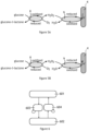
figure 5A and figure 5B , the mediator, preferably Prussian blue, allows both oxidation and reduction ofH 202 for respectively transferring electrons or capturing electrons from the electrode it is fixed on. - With reference to
figure 5A , for an applied voltage being under an applied threshold potential Vt between the workingelectrode 4 and a pseudo-reference electrode, said threshold potential being chosen between 20 mV and 650 mV, themediator 9 is configured for reducing H2O2 which is produced by theenzyme 8. Then, themediator 9, which is in an oxidized state, can be reduced at the workingelectrode 4. The working electrode gives electrons to themediator 9, and a negative current takes place between the working electrode 4and the pseudo-reference electrode. - With reference to
figure 5B , for an applied voltage being over an applied threshold potential Vt between the working electrode and a pseudo-reference electrode, said threshold potential being chosen between 20 mV and 650 mV, themediator 9 is configured for oxidizing H2O2 which is produced by theenzyme 8. Then, themediator 9, which is in a reduced state, can be oxidized at the workingelectrode 4. The workingelectrode 4 takes electrons from themediator 9, and a positive current takes place between the workingelectrode 4 and the pseudo-reference electrode. - A porous membrane can, for example, be deposited on the metallic surface of the electrode.
Glucose oxidase enzymes 8 can be, for example, grafter on the membrane. Then, Prussian blue can be deposited on both the membrane and theglucose oxidase enzymes 8. - The surface area S of the working
electrode 4 covered with both theenzymes 8 and themediators 9 is preferably comprised between 20 000 µm2 and 600 000 µm2. - With reference to
figure 5 and figure 6 , an aspect of the invention is a method of measuring a human body analyte 2 in an interstitial fluid of a user by a device, and preferably measuring the concentration of said body analyte 2. - After inserting the
microneedles 7 of thedevice 1 in the skin of the user, more specifically in the dermis of the user, the method comprises: - a
step 601 of measuring a first electrical current I1 between the workingelectrode 4 and the pseudo-reference electrode 5 while applying a first potential V1 between the workingelectrode 4 and the pseudo-reference electrode 5, the first potential V1 being less than the threshold potential Vt, the magnitude of the first electrical current I1 being greater than the magnitude of a predetermined first threshold current It1, and further measuring an output electrical current I0 between the workingelectrode 4 and the pseudo-reference electrode 5 while applying a second electrical potential V2, the second electrical potential V2 being greater than the first electrical potential V1, or - a
step 602 of b) measuring a second electrical current I2 between the workingelectrode 4 and the pseudo-reference electrode 5 while applying a third electrical potential V3 between the workingelectrode 4 and the pseudo-reference electrode 5, the third potential V3 being greater than the threshold potential Vt, the magnitude of the second electrical current I2 being less than a magnitude of a predetermined second threshold current It2, and then measuring the output electrical current I0 while applying a fourth electrical potential V4, the fourth electrical potential V4 being inferior to the third electrical potential V3. - Therefore, it is possible to switch the predominant reaction path in order to transfer electrons from the
enzymes 8 to the workingelectrode 4, depending on the concentration of analyte 2 in the interstitial fluid. - Specifically,
step 601 allows to switch from a first potential V1 adapted to measure low concentrations of analytes 2 to a second potential V2 adapted to measure higher concentrations of analyte 2. The terms "low concentration" are used herein to define a concentration under 11 mM, and preferably than 7 mM. Typically, in order to be accurate when measuring low concentrations of analyte 2, the electron transfer implying a reduction of H2O2 and a reduction of the mediator at the electrode is adapted because it allows to avoid a contribution of interferent species in the measurement. When the concentration increases, it leads the magnitude of the current to increase. Over a magnitude of a predetermined first threshold current It1, this chemical pathway suffers from non-linearity and saturation. Then, a second potential V2, greater than V1, is applied between the working electrode and the pseudo-reference electrode in order to foster the chemical pathway adapted to high concentrations of analyte 2. Instep 601, the current I1 is measured when the first potential V1 is applied between the workingelectrode 4 and the pseudo-reference electrode 5. Instep 602, the current I2 is measured when the third potential V3 is applied between the workingelectrode 4 and the pseudo-reference electrode 5. - In reference with
figure 7 , the potential V2 is preferably higher than the potential Vt. Therefore, it is possible to impose in a majority way the chemical pathway adapted to the high concentrations of analyte 2. - Step 602 allows to switch from a third potential V3 adapted to measure high concentrations of analytes 2 to a fourth electrical potential V4, adapted to measure lower concentrations of analyte 2. The terms "high concentration" are used herein to define a concentration of analyte 2 greater than 11 mM, and preferably than 13 mM. Typically, in order to be accurate when measuring high concentrations of analyte 2, the electron transfer implying a oxidation of H2O2 and an oxidation of the
mediator 9 at the electrode, or a direct oxidation of H2O2 at the workingelectrode 4, is adapted because it avoids limiting the quantity of current due to themediator 9 quantity at the electrode. When the concentration of analyte 2 decreases, it leads the magnitude of the current to decrease. Under a magnitude of a predetermined second threshold current It2, this chemical pathway suffers from noise of the interferent species also reacting at this potential. Then, a fourth potential V4, lower than V3, is applied between the working electrode and the pseudo-reference electrode in order to foster the chemical pathway adapted to low concentrations of analyte 2. - In reference with
figure 7 , the potential V4 is preferably lower than the potential Vt. Therefore, it is possible to impose in a majority way the chemical pathway adapted to the low concentrations of analyte 2. - The method can preferably comprise both
steps - The method preferably comprises a repetition of
steps 603 and/orsteps 604, each step comprising measuring the current I0 between the workingelectrode 4 and the pseudo-reference electrode, and determining a concentration of the analyte 2 in the interstitial fluid from the value of the said current. The determination of the concentration can be done using predetermined calibration data, or simultaneous measurement of a reference analyte 2 concertation. Step 603 comprises measuring the output current I0 while applying an electrical potential V2, the electrical potential V2 being greater than the potential V1. Step 604 comprises measuring the output current I0 while applying an electrical potential V3, the electrical potential V3 being lower than the potential V4. - Preferably, step 603 or step 604 is repeated at a time between 10 s and 30 min, and preferably between 15 s and 15 min. Therefore, it is possible to record pseudo-continuously the analyte 2 concentration while both having the most precise reaction pathway to measure the analyte concentration.
- The surface area S of the working
electrode 4 is preferably comprised between 20 000 µm2 and 600 000 µm2. Therefore, it is possible to limit the electrical noise when measuring the output current Io while minimizing the size of themicroneedle 7 to reduce the pain of the user. Conversely, as the surface area S is limited, the conditions of thestep 601 and/or 602 can be expressed in terms of current density. - Because of different electron pathways, depending on the applied electrical potential between the working
electrode 4 and the pseudo-reference electrode, the presence of analyte can induce an oxidation between the metal of the working electrode and another species. Hence, the current measured between the electrodes atstep 603 and step 604 can be of opposite signs. Moreover, the first threshold current and the second threshold current can of opposite signs. - Experimentally, the inventors measured that the first threshold current It1 is preferably comprised between - 500 nA and -1 nA and, notably between - 200 nA and -1 nA. The second current threshold is preferably comprised between 50 nA and 1 µA, notably between 100 nA and 1 µA.
- The threshold potential Vt is preferably comprised between 10 mV and 650 mV, notably between 100 mV and 400 mV.
- With reference to
figure 8 , a method according to an embodiment of the invention may comprise a step a) wherein the second potential V2 is chosen between a potential comprised between a first threshold potential Vt1 and a second threshold potential Vt2, Vt1 and Vt1 being greater than V1 and Vt2 being greater than Vt1, and a potential greater than a second potential Vt2, as a function of the measurement of the first electrical current I1. A method according to an embodiment of the invention may also comprise a step b) wherein the fourth potential V4 is chosen between a potential comprised between a fourth threshold potential Vt4 and a third threshold potential Vt3, Vt3 and Vt4 being less than V3 and Vt4 being less than Vt3, and a potential less than a fourth potential Vt4, as a function of the measurement of the first electrical current I1. Preferably, the first threshold potential Vt1 can be equal to 10 mV, the second threshold potential Vt2 can be equal to 400 mV, the third threshold potential Vt3 can be equal to 400 mV, and/or the fourth threshold potential Vt4 can be equal to 10 mV. - Therefore, it is possible to define in a predetermined way a number of electrode working modes strictly greater than two, so as to work in a zone with linear current/voltage characteristics and avoiding saturation of the measured current. In the embodiment schematically illustrated in
figure 8 , three preferred working zones are predetermined by four threshold potentials. These zones may be suitable for the detection of hypoglycemia in a first zone (a), normal glucose in a second zone (b), and hyperglycemia in a third zone (c).
Claims (13)
- A method of measuring a human body analyte (2) concentration in an interstitial fluid of a user by a device (1) comprising:- a control unit (3),- at least a working electrode (4) and a pseudo-reference electrode (5), the working electrode (4) and the pseudo-reference electrode (5) being configured for an implantation in the dermis of the user by at least one microneedle (7) so as to be in contact with the interstitial fluid of the user,- an enzyme (8) configured for oxidizing the analyte (2), the enzyme (8) being attached to at least a part of the working electrode, characterized in that the device further comprises:- a mediator (9) being fixed on said part of the working electrode (4), the mediator (9) being a redox mediator (9) having a reduced state and an oxidized state, and being configured for being in a reduced state below a predetermined threshold electrical potential Vt, and in an oxidized state above the predetermined threshold electrical potential Vt, the method further characterized in that it further comprises the step of:a) measuring a first electrical current I1 between the working electrode (4) and the pseudo-reference electrode (5) while applying a first potential V1 between the working electrode (4) and the pseudo-reference electrode (5), the first potential V1 being less than the predetermined threshold potential Vt, the magnitude of the first electrical current I1 being greater than the magnitude of a predetermined first threshold current It1, and further measuring an output electrical current I0 between the working electrode (4) and the pseudo-reference electrode (5) while applying a second electrical potential V2, the second electrical potential V2 being greater than the first electrical potential V1,
and/or further comprises the step ofb) measuring a second electrical current I2 between the working electrode (4) and the pseudo-reference electrode (5) while applying a third electrical potential V3 between the working electrode (4) and the pseudo-reference electrode (5), the third potential V3 being greater than the predetermined threshold potential Vt, the magnitude of the second electrical current I2 being less than a magnitude of a predetermined second threshold current It2, and then measuring the output electrical current I0 while applying a fourth electrical potential V4, the fourth electrical potential V4 being inferior to the third electrical potential V3. - The method of claim 1, the method comprising the step of:a) measuring a first electrical current I1 between the working electrode (4) and the pseudo-reference electrode (5) while applying a first potential V1 between the working electrode (4) and the pseudo-reference electrode (5), the first potential V1 being less than a predetermined threshold potential Vt, the magnitude of the first electrical current I1 being greater than the magnitude of a predetermined first threshold current It1, and further measuring an output electrical current I0 between the working electrode (4) and the pseudo-reference electrode (5) while applying a second electrical potential V2, the second electrical potential V2 being greater than the first electrical potential V1,wherein the second electrical potential V2 is greater than the threshold electrical potential Vt.
- The method of claim 1 or claim 2, the method comprising the step of:
b) measuring a second electrical current I2 between the working electrode (4) and the pseudo-reference electrode (5) while applying a third electrical potential V3 between the working electrode (4) and the pseudo-reference electrode (5), the third potential V3 being greater than the threshold potential Vt, the magnitude of the second electrical current I2 being less than a magnitude of a predetermined second threshold current It2, and then measuring the output electrical current I0 while applying a fourth electrical potential V4, the fourth electrical potential V4 being inferior to the third electrical potential V3, wherein the fourth electrical potential V4 is under the threshold electrical potential Vt. - The method according to any of claims 1 to 3, comprising both step a) and step b).
- The method according to any of claims 1 to 4, wherein step a) and/or step b) comprise(s) a sub-step of computing a concentration of the analyte in the interstitial fluid from the value of the output electrical current Io.
- The method according to any of claims 1 to 5, wherein the first threshold current It1 and the second threshold It2 current are of opposite signs.
- The method according to any of claims 1 to 6, comprising a repetition of the steps of measuring the current between the working electrode (4) and the pseudo-reference electrode and determining a concentration of the analyte (2) in the interstitial fluid from the value of the output electrical current I0.
- The method according to claim 7, wherein each repetition is separated by a time between 0.5 s and 30 min, and preferably between 15 s and 15 min.
- The method according to claim 8, wherein the threshold potential Vt is comprised between 10 mV and 650 mV.
- The method according to claims 1 to 9, wherein the first threshold current It1 is comprised in the range from - 500 nA and -0,1 nA and preferably between - 200 nA and -0,1 nA.
- The method according to any of claims 1 to 10, wherein the enzyme (8) configured for oxidizing the analyte (2) is at least chosen between an enzyme configured for oxidizing glucose and an enzyme configured for oxidizing lactate.
- The method according to any of claims 1 to 11, wherein the mediator (9) is Prussian blue.
- A device (1) for measuring a human body analyte (2) in an interstitial fluid of a user comprising:- a control unit (3),- at least a working electrode (4) and a pseudo-reference electrode (5), the working electrode (4) and the pseudo-reference electrode (5) being configured for an implantation in the dermis of the user by at least one microneedle (7) so as to be in contact with the interstitial fluid of the user,- an enzyme (8) configured for oxidizing the analyte (2), the enzyme (8) being attached over at least a part of the working electrode, characterized in that the device further comprises:- a mediator (9) being fixed on said part of the working electrode (4), the mediator (9) being a redox mediator (9) having a reduced state and an oxidized state, and being configured for being in a reduced state below the predetermined threshold electrical potential Vt, and in an oxidized state above the predetermined threshold electrical potential Vt,and in that the control unit is configured for:a) measuring a first electrical current I1 between the working electrode (4) and the pseudo-reference electrode (5) while applying a first potential V1 between the working electrode (4) and the pseudo-reference electrode (5), the first potential V1 being less than a predetermined threshold potential Vt, the magnitude of the first electrical current I1 being greater than the magnitude of a predetermined first threshold current It1, and further measuring an output electrical current I0 between the working electrode (4) and the pseudo-reference electrode (5) while applying a second electrical potential V2, the second electrical potential V2 being greater than the first electrical potential V1,
and/or forb) measuring a second electrical current I2 between the working electrode (4) and the pseudo-reference electrode (5) while applying a third electrical potential V3 between the working electrode (4) and the pseudo-reference electrode (5), the third potential V3 being greater than the threshold potential Vt, the magnitude of the second electrical current I2 being less than a magnitude of a predetermined second threshold current It2, and then measuring the output electrical current I0 while applying a fourth electrical potential V4, the fourth electrical potential V4 being inferior to the third electrical potential V3.
Applications Claiming Priority (2)
| Application Number | Priority Date | Filing Date | Title |
|---|---|---|---|
| EP20305032.3A EP3851040A1 (en) | 2020-01-16 | 2020-01-16 | Body monitoring device and associated method |
| PCT/EP2021/050964 WO2021144472A1 (en) | 2020-01-16 | 2021-01-18 | Body monitoring device and associated method |
Publications (2)
| Publication Number | Publication Date |
|---|---|
| EP4090242A1 EP4090242A1 (en) | 2022-11-23 |
| EP4090242B1 true EP4090242B1 (en) | 2025-01-08 |
Family
ID=69467490
Family Applications (2)
| Application Number | Title | Priority Date | Filing Date |
|---|---|---|---|
| EP20305032.3A Withdrawn EP3851040A1 (en) | 2020-01-16 | 2020-01-16 | Body monitoring device and associated method |
| EP21701265.7A Active EP4090242B1 (en) | 2020-01-16 | 2021-01-18 | Body monitoring device and associated method |
Family Applications Before (1)
| Application Number | Title | Priority Date | Filing Date |
|---|---|---|---|
| EP20305032.3A Withdrawn EP3851040A1 (en) | 2020-01-16 | 2020-01-16 | Body monitoring device and associated method |
Country Status (3)
| Country | Link |
|---|---|
| US (1) | US20230038624A1 (en) |
| EP (2) | EP3851040A1 (en) |
| WO (1) | WO2021144472A1 (en) |
Families Citing this family (1)
| Publication number | Priority date | Publication date | Assignee | Title |
|---|---|---|---|---|
| US12238906B2 (en) * | 2023-01-17 | 2025-02-25 | Toyota Motor Engineering & Manufacturing North America, Inc. | Power electronic device assemblies having heat spreaders and electrically insulating layer |
Family Cites Families (8)
| Publication number | Priority date | Publication date | Assignee | Title |
|---|---|---|---|---|
| US8066866B2 (en) * | 2005-10-17 | 2011-11-29 | Lifescan, Inc. | Methods for measuring physiological fluids |
| EP2283149A1 (en) * | 2008-05-13 | 2011-02-16 | General Atomics | Electrochemical biosensor for direct determination of percentage of glycated hemoglobin |
| US10987039B2 (en) * | 2014-12-03 | 2021-04-27 | Stmicroelectronics S.R.L. | Microneedle array device and method of making |
| US9855000B2 (en) * | 2015-05-18 | 2018-01-02 | Milo Sensors, Inc. | Transdermal analyte sensing device |
| US20170038331A1 (en) * | 2015-08-05 | 2017-02-09 | Lifescan Scotland Limited | System and method for compensating sample-related measurements based on polarization effects of test strips |
| SI3220137T1 (en) * | 2016-03-14 | 2019-05-31 | F. Hoffmann-La Roche Ag | Method for detecting an interferent contribution in a biosensor |
| EP3522774A1 (en) * | 2016-10-07 | 2019-08-14 | Debiotech S.A. | Micro sensor |
| US11278217B2 (en) * | 2017-03-31 | 2022-03-22 | RichHealth Technology Corporation | Transdermal microneedle array patch |
-
2020
- 2020-01-16 EP EP20305032.3A patent/EP3851040A1/en not_active Withdrawn
-
2021
- 2021-01-18 US US17/793,106 patent/US20230038624A1/en active Pending
- 2021-01-18 WO PCT/EP2021/050964 patent/WO2021144472A1/en not_active Ceased
- 2021-01-18 EP EP21701265.7A patent/EP4090242B1/en active Active
Also Published As
| Publication number | Publication date |
|---|---|
| WO2021144472A1 (en) | 2021-07-22 |
| EP4090242A1 (en) | 2022-11-23 |
| EP3851040A1 (en) | 2021-07-21 |
| US20230038624A1 (en) | 2023-02-09 |
Similar Documents
| Publication | Publication Date | Title |
|---|---|---|
| US11091790B2 (en) | Determining analyte concentration from variant concentration distribution in measurable species | |
| JP4385219B2 (en) | Concentration measurement method | |
| EP1678492A1 (en) | Electrochemical test strip for reducing the effect of direct and mediated interference current | |
| US20220304599A1 (en) | Analyte sensor | |
| TW202107078A (en) | Micro biosensor and method for reducing measurement interference using the same | |
| US12507924B2 (en) | Analyte sensor and a method for producing an analyte sensor | |
| Perdomo et al. | Containment sensors for the determination of L-lactate and glucose | |
| US20230038624A1 (en) | Body monitoring device and associated method | |
| Carducci et al. | Glucometers and Continuous Glucose Monitors | |
| Rankin et al. | Non-Mediated Glucose Biosensing Using Nanostructured TiO~ 2 | |
| KR20040017605A (en) | Method of determining concentration of glucose using alternative current impedance |
Legal Events
| Date | Code | Title | Description |
|---|---|---|---|
| STAA | Information on the status of an ep patent application or granted ep patent |
Free format text: STATUS: UNKNOWN |
|
| STAA | Information on the status of an ep patent application or granted ep patent |
Free format text: STATUS: THE INTERNATIONAL PUBLICATION HAS BEEN MADE |
|
| PUAI | Public reference made under article 153(3) epc to a published international application that has entered the european phase |
Free format text: ORIGINAL CODE: 0009012 |
|
| STAA | Information on the status of an ep patent application or granted ep patent |
Free format text: STATUS: REQUEST FOR EXAMINATION WAS MADE |
|
| 17P | Request for examination filed |
Effective date: 20220810 |
|
| AK | Designated contracting states |
Kind code of ref document: A1 Designated state(s): AL AT BE BG CH CY CZ DE DK EE ES FI FR GB GR HR HU IE IS IT LI LT LU LV MC MK MT NL NO PL PT RO RS SE SI SK SM TR |
|
| DAV | Request for validation of the european patent (deleted) | ||
| DAX | Request for extension of the european patent (deleted) | ||
| 19U | Interruption of proceedings before grant |
Effective date: 20230427 |
|
| 19W | Proceedings resumed before grant after interruption of proceedings |
Effective date: 20240603 |
|
| RAP3 | Party data changed (applicant data changed or rights of an application transferred) |
Owner name: WIZP AS |
|
| GRAP | Despatch of communication of intention to grant a patent |
Free format text: ORIGINAL CODE: EPIDOSNIGR1 |
|
| STAA | Information on the status of an ep patent application or granted ep patent |
Free format text: STATUS: GRANT OF PATENT IS INTENDED |
|
| INTG | Intention to grant announced |
Effective date: 20241016 |
|
| RIN1 | Information on inventor provided before grant (corrected) |
Inventor name: PEACOCK, MARTIN Inventor name: PIERART, LUC |
|
| GRAS | Grant fee paid |
Free format text: ORIGINAL CODE: EPIDOSNIGR3 |
|
| GRAA | (expected) grant |
Free format text: ORIGINAL CODE: 0009210 |
|
| STAA | Information on the status of an ep patent application or granted ep patent |
Free format text: STATUS: THE PATENT HAS BEEN GRANTED |
|
| AK | Designated contracting states |
Kind code of ref document: B1 Designated state(s): AL AT BE BG CH CY CZ DE DK EE ES FI FR GB GR HR HU IE IS IT LI LT LU LV MC MK MT NL NO PL PT RO RS SE SI SK SM TR |
|
| REG | Reference to a national code |
Ref country code: GB Ref legal event code: FG4D |
|
| REG | Reference to a national code |
Ref country code: CH Ref legal event code: EP |
|
| REG | Reference to a national code |
Ref country code: DE Ref legal event code: R096 Ref document number: 602021024637 Country of ref document: DE |
|
| REG | Reference to a national code |
Ref country code: IE Ref legal event code: FG4D |
|
| PGFP | Annual fee paid to national office [announced via postgrant information from national office to epo] |
Ref country code: AT Payment date: 20250417 Year of fee payment: 5 |
|
| REG | Reference to a national code |
Ref country code: LT Ref legal event code: MG9D |
|
| REG | Reference to a national code |
Ref country code: NL Ref legal event code: MP Effective date: 20250108 |
|
| REG | Reference to a national code |
Ref country code: AT Ref legal event code: MK05 Ref document number: 1757792 Country of ref document: AT Kind code of ref document: T Effective date: 20250108 |
|
| PG25 | Lapsed in a contracting state [announced via postgrant information from national office to epo] |
Ref country code: NL Free format text: LAPSE BECAUSE OF FAILURE TO SUBMIT A TRANSLATION OF THE DESCRIPTION OR TO PAY THE FEE WITHIN THE PRESCRIBED TIME-LIMIT Effective date: 20250108 |
|
| PG25 | Lapsed in a contracting state [announced via postgrant information from national office to epo] |
Ref country code: RS Free format text: LAPSE BECAUSE OF FAILURE TO SUBMIT A TRANSLATION OF THE DESCRIPTION OR TO PAY THE FEE WITHIN THE PRESCRIBED TIME-LIMIT Effective date: 20250408 |
|
| PG25 | Lapsed in a contracting state [announced via postgrant information from national office to epo] |
Ref country code: FI Free format text: LAPSE BECAUSE OF FAILURE TO SUBMIT A TRANSLATION OF THE DESCRIPTION OR TO PAY THE FEE WITHIN THE PRESCRIBED TIME-LIMIT Effective date: 20250108 |
|
| PG25 | Lapsed in a contracting state [announced via postgrant information from national office to epo] |
Ref country code: PL Free format text: LAPSE BECAUSE OF FAILURE TO SUBMIT A TRANSLATION OF THE DESCRIPTION OR TO PAY THE FEE WITHIN THE PRESCRIBED TIME-LIMIT Effective date: 20250108 |
|
| PG25 | Lapsed in a contracting state [announced via postgrant information from national office to epo] |
Ref country code: ES Free format text: LAPSE BECAUSE OF FAILURE TO SUBMIT A TRANSLATION OF THE DESCRIPTION OR TO PAY THE FEE WITHIN THE PRESCRIBED TIME-LIMIT Effective date: 20250108 |
|
| PG25 | Lapsed in a contracting state [announced via postgrant information from national office to epo] |
Ref country code: IS Free format text: LAPSE BECAUSE OF FAILURE TO SUBMIT A TRANSLATION OF THE DESCRIPTION OR TO PAY THE FEE WITHIN THE PRESCRIBED TIME-LIMIT Effective date: 20250508 Ref country code: NO Free format text: LAPSE BECAUSE OF FAILURE TO SUBMIT A TRANSLATION OF THE DESCRIPTION OR TO PAY THE FEE WITHIN THE PRESCRIBED TIME-LIMIT Effective date: 20250408 |
|
| PG25 | Lapsed in a contracting state [announced via postgrant information from national office to epo] |
Ref country code: HR Free format text: LAPSE BECAUSE OF FAILURE TO SUBMIT A TRANSLATION OF THE DESCRIPTION OR TO PAY THE FEE WITHIN THE PRESCRIBED TIME-LIMIT Effective date: 20250108 |
|
| PG25 | Lapsed in a contracting state [announced via postgrant information from national office to epo] |
Ref country code: LV Free format text: LAPSE BECAUSE OF FAILURE TO SUBMIT A TRANSLATION OF THE DESCRIPTION OR TO PAY THE FEE WITHIN THE PRESCRIBED TIME-LIMIT Effective date: 20250108 Ref country code: PT Free format text: LAPSE BECAUSE OF FAILURE TO SUBMIT A TRANSLATION OF THE DESCRIPTION OR TO PAY THE FEE WITHIN THE PRESCRIBED TIME-LIMIT Effective date: 20250508 |
|
| PG25 | Lapsed in a contracting state [announced via postgrant information from national office to epo] |
Ref country code: GR Free format text: LAPSE BECAUSE OF FAILURE TO SUBMIT A TRANSLATION OF THE DESCRIPTION OR TO PAY THE FEE WITHIN THE PRESCRIBED TIME-LIMIT Effective date: 20250409 Ref country code: BG Free format text: LAPSE BECAUSE OF FAILURE TO SUBMIT A TRANSLATION OF THE DESCRIPTION OR TO PAY THE FEE WITHIN THE PRESCRIBED TIME-LIMIT Effective date: 20250108 |
|
| PGFP | Annual fee paid to national office [announced via postgrant information from national office to epo] |
Ref country code: CH Payment date: 20250424 Year of fee payment: 5 |
|
| PG25 | Lapsed in a contracting state [announced via postgrant information from national office to epo] |
Ref country code: AT Free format text: LAPSE BECAUSE OF FAILURE TO SUBMIT A TRANSLATION OF THE DESCRIPTION OR TO PAY THE FEE WITHIN THE PRESCRIBED TIME-LIMIT Effective date: 20250108 |
|
| PG25 | Lapsed in a contracting state [announced via postgrant information from national office to epo] |
Ref country code: SE Free format text: LAPSE BECAUSE OF FAILURE TO SUBMIT A TRANSLATION OF THE DESCRIPTION OR TO PAY THE FEE WITHIN THE PRESCRIBED TIME-LIMIT Effective date: 20250108 |
|
| PG25 | Lapsed in a contracting state [announced via postgrant information from national office to epo] |
Ref country code: LU Free format text: LAPSE BECAUSE OF NON-PAYMENT OF DUE FEES Effective date: 20250118 |
|
| PG25 | Lapsed in a contracting state [announced via postgrant information from national office to epo] |
Ref country code: SM Free format text: LAPSE BECAUSE OF FAILURE TO SUBMIT A TRANSLATION OF THE DESCRIPTION OR TO PAY THE FEE WITHIN THE PRESCRIBED TIME-LIMIT Effective date: 20250108 |
|
| REG | Reference to a national code |
Ref country code: DE Ref legal event code: R097 Ref document number: 602021024637 Country of ref document: DE |
|
| PG25 | Lapsed in a contracting state [announced via postgrant information from national office to epo] |
Ref country code: DK Free format text: LAPSE BECAUSE OF FAILURE TO SUBMIT A TRANSLATION OF THE DESCRIPTION OR TO PAY THE FEE WITHIN THE PRESCRIBED TIME-LIMIT Effective date: 20250108 |
|
| PG25 | Lapsed in a contracting state [announced via postgrant information from national office to epo] |
Ref country code: MC Free format text: LAPSE BECAUSE OF FAILURE TO SUBMIT A TRANSLATION OF THE DESCRIPTION OR TO PAY THE FEE WITHIN THE PRESCRIBED TIME-LIMIT Effective date: 20250108 |
|
| PG25 | Lapsed in a contracting state [announced via postgrant information from national office to epo] |
Ref country code: BE Free format text: LAPSE BECAUSE OF NON-PAYMENT OF DUE FEES Effective date: 20250131 |
|
| PG25 | Lapsed in a contracting state [announced via postgrant information from national office to epo] |
Ref country code: EE Free format text: LAPSE BECAUSE OF FAILURE TO SUBMIT A TRANSLATION OF THE DESCRIPTION OR TO PAY THE FEE WITHIN THE PRESCRIBED TIME-LIMIT Effective date: 20250108 Ref country code: CZ Free format text: LAPSE BECAUSE OF FAILURE TO SUBMIT A TRANSLATION OF THE DESCRIPTION OR TO PAY THE FEE WITHIN THE PRESCRIBED TIME-LIMIT Effective date: 20250108 |
|
| REG | Reference to a national code |
Ref country code: BE Ref legal event code: MM Effective date: 20250131 |
|
| PG25 | Lapsed in a contracting state [announced via postgrant information from national office to epo] |
Ref country code: RO Free format text: LAPSE BECAUSE OF FAILURE TO SUBMIT A TRANSLATION OF THE DESCRIPTION OR TO PAY THE FEE WITHIN THE PRESCRIBED TIME-LIMIT Effective date: 20250108 |
|
| PG25 | Lapsed in a contracting state [announced via postgrant information from national office to epo] |
Ref country code: SK Free format text: LAPSE BECAUSE OF FAILURE TO SUBMIT A TRANSLATION OF THE DESCRIPTION OR TO PAY THE FEE WITHIN THE PRESCRIBED TIME-LIMIT Effective date: 20250108 |
|
| PLBE | No opposition filed within time limit |
Free format text: ORIGINAL CODE: 0009261 |
|
| STAA | Information on the status of an ep patent application or granted ep patent |
Free format text: STATUS: NO OPPOSITION FILED WITHIN TIME LIMIT |
|
| RAP4 | Party data changed (patent owner data changed or rights of a patent transferred) |
Owner name: WIZP AS |
|
| 26N | No opposition filed |
Effective date: 20251009 |
|
| PGFP | Annual fee paid to national office [announced via postgrant information from national office to epo] |
Ref country code: FR Payment date: 20251212 Year of fee payment: 6 |
|
| PG25 | Lapsed in a contracting state [announced via postgrant information from national office to epo] |
Ref country code: IE Free format text: LAPSE BECAUSE OF NON-PAYMENT OF DUE FEES Effective date: 20250118 |
|
| PG25 | Lapsed in a contracting state [announced via postgrant information from national office to epo] |
Ref country code: IT Free format text: LAPSE BECAUSE OF FAILURE TO SUBMIT A TRANSLATION OF THE DESCRIPTION OR TO PAY THE FEE WITHIN THE PRESCRIBED TIME-LIMIT Effective date: 20250108 |
|
| PGFP | Annual fee paid to national office [announced via postgrant information from national office to epo] |
Ref country code: GB Payment date: 20260127 Year of fee payment: 6 |
|
| PGFP | Annual fee paid to national office [announced via postgrant information from national office to epo] |
Ref country code: DE Payment date: 20260114 Year of fee payment: 6 |