EP4090117A1 - Data frame transmission method, data frame transmission device, and storage medium - Google Patents
Data frame transmission method, data frame transmission device, and storage medium Download PDFInfo
- Publication number
- EP4090117A1 EP4090117A1 EP20912231.6A EP20912231A EP4090117A1 EP 4090117 A1 EP4090117 A1 EP 4090117A1 EP 20912231 A EP20912231 A EP 20912231A EP 4090117 A1 EP4090117 A1 EP 4090117A1
- Authority
- EP
- European Patent Office
- Prior art keywords
- data frame
- link
- retransmission
- transmission
- counting
- Prior art date
- Legal status (The legal status is an assumption and is not a legal conclusion. Google has not performed a legal analysis and makes no representation as to the accuracy of the status listed.)
- Granted
Links
Images


Classifications
-
- H—ELECTRICITY
- H04—ELECTRIC COMMUNICATION TECHNIQUE
- H04L—TRANSMISSION OF DIGITAL INFORMATION, e.g. TELEGRAPHIC COMMUNICATION
- H04L47/00—Traffic control in data switching networks
- H04L47/10—Flow control; Congestion control
- H04L47/27—Evaluation or update of window size, e.g. using information derived from acknowledged [ACK] packets
-
- H—ELECTRICITY
- H04—ELECTRIC COMMUNICATION TECHNIQUE
- H04L—TRANSMISSION OF DIGITAL INFORMATION, e.g. TELEGRAPHIC COMMUNICATION
- H04L1/00—Arrangements for detecting or preventing errors in the information received
- H04L1/12—Arrangements for detecting or preventing errors in the information received by using return channel
- H04L1/16—Arrangements for detecting or preventing errors in the information received by using return channel in which the return channel carries supervisory signals, e.g. repetition request signals
- H04L1/1607—Details of the supervisory signal
- H04L1/1642—Formats specially adapted for sequence numbers
-
- H—ELECTRICITY
- H04—ELECTRIC COMMUNICATION TECHNIQUE
- H04L—TRANSMISSION OF DIGITAL INFORMATION, e.g. TELEGRAPHIC COMMUNICATION
- H04L47/00—Traffic control in data switching networks
- H04L47/10—Flow control; Congestion control
- H04L47/34—Flow control; Congestion control ensuring sequence integrity, e.g. using sequence numbers
-
- H—ELECTRICITY
- H04—ELECTRIC COMMUNICATION TECHNIQUE
- H04L—TRANSMISSION OF DIGITAL INFORMATION, e.g. TELEGRAPHIC COMMUNICATION
- H04L47/00—Traffic control in data switching networks
- H04L47/10—Flow control; Congestion control
- H04L47/41—Flow control; Congestion control by acting on aggregated flows or links
-
- H—ELECTRICITY
- H04—ELECTRIC COMMUNICATION TECHNIQUE
- H04W—WIRELESS COMMUNICATION NETWORKS
- H04W72/00—Local resource management
- H04W72/12—Wireless traffic scheduling
-
- H—ELECTRICITY
- H04—ELECTRIC COMMUNICATION TECHNIQUE
- H04W—WIRELESS COMMUNICATION NETWORKS
- H04W76/00—Connection management
- H04W76/10—Connection setup
- H04W76/15—Setup of multiple wireless link connections
-
- H—ELECTRICITY
- H04—ELECTRIC COMMUNICATION TECHNIQUE
- H04W—WIRELESS COMMUNICATION NETWORKS
- H04W84/00—Network topologies
- H04W84/02—Hierarchically pre-organised networks, e.g. paging networks, cellular networks, WLAN [Wireless Local Area Network] or WLL [Wireless Local Loop]
- H04W84/10—Small scale networks; Flat hierarchical networks
- H04W84/12—WLAN [Wireless Local Area Networks]
Definitions
- the present disclosure relates to the field of communication technologies, and in particular, to a method and an apparatus for data frame transmission, and a storage medium.
- Wi-Fi Wireless Fidelity
- Wi-Fi Wireless Fidelity
- data frames can be transmitted under multiple links. Under multiple links, the transmission of the data frame may be switched from one link to another.
- the present disclosure provides a method and an apparatus for data frame transmission and a storage medium.
- a method for data frame transmission includes: determining that transmission of a data frame is switched from a first link to a second link; and in response to the transmission of the data frame being switched from the first link to the second link, performing retransmission counting of the data frame on the second link.
- performing the retransmission counting of the data frame on the second link includes: performing the retransmission counting of the data frame on the second link by setting a retransmission count value of the data frame corresponding to the second link to zero and reassigning a transmission identifier and/or a sequence number for the data frame.
- the method involved in embodiments of the present disclosure further includes: terminating retransmission counting of the data frame on the first link.
- the method involved in embodiments of the present disclosure further includes: determining that a clock for transmitting the data frame is invalid, or determining that the clock for transmitting the data frame is invalid and a contention window for retransmitting the data frame on the first link has a maximum value; activating the clock for transmitting the data frame.
- performing the retransmission counting of the data frame on the second link includes: performing the retransmission counting of the data frame on the second link by taking a retransmission count value of the data frame corresponding to the first link as an initial value of a retransmission count value of the data frame corresponding to the second link; continuing to use a transmission identifier and/or a sequence number of the data frame corresponding to the first link as a transmission identifier and/or a sequence number of the data frame corresponding to the second link.
- the method involved in embodiments of the present disclosure further includes: determining that a clock for performing the retransmission counting of the data frame is valid; or determining that a contention window for performing the retransmission counting of the data frame on the first link has a maximum value.
- performing the retransmission counting of the data frame includes: initializing a contention window, and increasing a retransmission count value in response to retransmission of the data frame until the contention window reaches a maximum value.
- the method involved in embodiments of the present disclosure further includes: in response to the successful transmission of the data frame, initializing the retransmission count value to zero.
- an apparatus for data frame transmission includes: a switching unit, configured to determine that transmission of a data frame is switched from a first link to a second link; a retransmission counting unit, configured to, in response to the transmission of the data frame being switched from the first link to the second link, perform retransmission counting of the data frame on the second link.
- the retransmission counting unit is configured to perform the retransmission counting of the data frame on the second link by setting a retransmission count value of the data frame corresponding to the second link to zero and reassigning a transmission identifier and/or a sequence number for the data frame.
- the retransmission counting unit is further configured to: terminate retransmission counting of the data frame on the first link.
- the retransmission counting unit is further configured to: determine that a clock for transmitting the data frame is invalid; or determine that the clock for transmitting the data frame is invalid and a contention window for retransmitting the data frame on the first link has a maximum value; activating the clock for transmitting the data frame.
- the retransmission counting unit is configured to: perform the retransmission counting of the data frame on the second link by taking a retransmission count value of the data frame corresponding to the first link as an initial value of a retransmission count value of the data frame corresponding to the second link; continue to use a transmission identifier and/or a sequence number of the data frame corresponding to the first link as a transmission identifier and/or a sequence number of the data frame corresponding to the second link.
- the retransmission counting unit is further configured to: determine that a clock for performing the retransmission counting of the data frame is valid; or determine that a contention window for performing the retransmission counting of the data frame on the first link has a maximum value.
- the retransmission counting unit is configured to perform retransmission counting by: initializing a contention window, and increasing a retransmission count value in response to retransmission of the data frame until the contention window reaches a maximum value.
- the retransmission counting unit is further configured to: in response to the successful transmission of the data frame, initialize the retransmission count value to zero.
- an apparatus for data frame transmission including:
- a non-transitory computer readable storage medium When instructions in the storage medium are executed by a processor, the processor is enabled to implement the method for data frame transmission described in the first aspect or any implementation of the first aspect.
- the technical solutions provided by the embodiments of the present disclosure may include the following beneficial effects.
- the retransmission counting of the data frame is performed on the second link, so as to realize counting of data frame retransmission when switching of data frame transmission occurs.
- the method for data frame transmission is applied to a wireless local area network communication system including a data sending device and a data receiving device.
- the data sending device and the data receiving device may be a station (STA) or an access point (AP).
- STA station
- AP access point
- the forward transmission and backhaul of data are performed between the data sending device and the data receiving device through the wireless local area network.
- the STA involved in the present disclosure may be understood as a user terminal in the wireless local area network, and the user terminal may be referred to as user equipment (UE), mobile station (MS), mobile terminal (MT), etc., which is a device that provides voice and/or data connectivity to a user.
- the terminal may be a handheld device with a wireless connection function, a vehicle-mounted device, and the like.
- some examples of terminals are: Smart Phone (Mobile Phone), Pocket Personal Computer (PPC), Handheld Computer, Personal Digital Assistant (PDA), Notebook Computer, Tablet Computer, Wearable Device, Internet of Things (IoT) client or in-vehicle device, etc.
- the AP involved in the present disclosure refers to a device, a router, and the like that the user terminal in the wireless local area network accesses the network.
- IEEE802.11 standard is used for data frame transmission between the STA and the AP.
- IEEE802.11 has established the SG (study group) IEEE802.11be to study the next-generation mainstream Wi-Fi technology.
- the research scope is: 320MHz bandwidth transmission, aggregation and coordination of multiple frequency bands, etc.
- the proposed vision is: compared with the existing IEEE802.11ax, the speed and throughput are increased by at least four times. Its main application scenarios are video transmission, AR, VR, etc.
- the aggregation and coordination of multiple frequency bands refers to simultaneous communication in multiple frequency bands or multiple bandwidths in the same frequency band, for example, simultaneous communication in three frequency bands of 2.4GHz, 5GHz, and 6-7GHz. Simultaneous communication in multiple frequency bands or multiple bandwidths in the same frequency can be understood as multi-link communication, or called multi-link aggregation (MLA).
- MLA multi-link aggregation
- Data frames are transmitted under multiple links.
- Data frames with the same Quality of Service (QoS) requirement are assigned the same Traffic Identify (TID), or data frames having the same content and assigned the same Sequence Number (SN) are also assigned the same TID.
- QoS Quality of Service
- SN Sequence Number
- the data frame retransmission counting is performed. For example, a STA short retry count (SSRC) and a STA long retry count (SLRC) are performed.
- SSRC STA short retry count
- SLRC STA long retry count
- a clock for data frame transmission is set, and for different links, data frame retransmission counts (counts of SSRC and/or SLRC) are independent of each other.
- an initial value of the data frame retransmission count (the count of SSRC and/or SLRC) under each link is set to 0.
- the retransmission count value increases one by one, and the contention window (CW) also increases accordingly.
- the retransmission count value increases until the CW window reaches the maximum value and does not increase and remains unchanged. It can be understood that if the CW window is at the maximum value, but the clock used for data frame transmission does not reach the maximum value, the data frame retransmission count (the count of SSRC and/or SLRC) does not increase and remains unchanged.
- Embodiment of the present disclosure provides a method for data frame transmission.
- the retransmission counting of the data frame is performed on the second link, so as to realize counting of data frame retransmission when switching of data frame transmission occurs.
- FIG. 1 is a flowchart of a method for data frame transmission according to an exemplary embodiment. As shown in FIG. 1 , the method for data frame transmission is applied in a station or an AP, and includes the following steps.
- step S11 it is determined that transmission of a data frame is switched from a first link to a second link.
- the data frame is transmitted under multiple links, and can be switched between links.
- the link where the data frame is before switching is called the first link
- the link where the data frame is after switching is called the second link.
- step S12 in response to the transmission of the data frame being switched from the first link to the second link, retransmission counting of the data frame is performed on the second link.
- the retransmission counting of the data frame on the second link may be performed in the following manner 1 or manner 2.
- Manner 1 On the second link, a retransmission count value of the data frame is set to zero, and then the retransmission counting is performed, and TID and/or SN are reassigned to the data frame.
- the retransmission count value of the data frame corresponding to the second link is set to zero, and the TID and/or SN are reassigned to the data frame, so that the retransmission counting of the data frame is accordingly performed on the second link.
- the retransmission counting is performed after the retransmission count value of the data frame is set to zero, which can be understood as the retransmission counting performed on the data frame as a newly transmitted data frame on the second link.
- the SSRC and/or SLRC are initialized, and the count value of the SSRC and/or SLRC is set to zero, so as to perform the retransmission counting of the data frame on the second link.
- the retransmission count value of the data frame is set to zero and then the retransmission counting is performed, and the TID and/or SN are reassigned to the data frame.
- the retransmission counting of the data frame on the first link may be terminated.
- assigning TID and/or SN to the data frame refers to:
- TID and/or SN may be reassigned to the data frame. That is: when the reassignment reassigns TID and/or SN for the data frame, the TID and SN are reassigned for the data frame transmitted on the second link; or, when the reassignment reassigns TID and/or SN for the data frame, TID is reassigned for the data frame transmitted on the second link, and the manner of determining the SN of the second link is not limited; or, when the reassignment reassigns the TID and/or SN for the data frame, the SN is reassigned for the data frame transmitted on the second link, and the manner for determining the TID of the second link is not limited.
- re-counting of data frame retransmission is performed on the second link. It can be understood that, when the retransmission counting of the data frame is performed on the second link in the first manner, it can be performed in response to determining that the clock used for data frame transmission is invalid or determining that the clock used for data frame transmission is invalid and the CW window is at the maximum value.
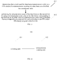
- FIG. 2 is a flowchart of a method for data frame transmission according to an exemplary embodiment. As shown in Fig. 2 , the method for data frame transmission is applied in a station or an AP, and includes the following steps.
- step S21 it is determined that a clock used for data frame transmission is invalid, or it is determined that a clock used for data frame transmission is invalid and a CW window has a maximum value.
- step S22 retransmission counting of a data frame on a first link is terminated, and a clock for transmitting the data frame is activated.
- step S23 a retransmission count value of the data frame corresponding to the second link is set to zero, and a TID and/or a SN are reassigned to the data frame, so that the retransmission counting of the data frame is correspondingly performed on the second link.
- the retransmission counting of the data frame is re-counted on the second link, so as to realize counting of the data frame retransmission when switching of the data frame transmission occurs.
- the clock of the first link fails, the retransmission of the data frame is counted.
- Manner 2 On the second link, the retransmission counting is performed by taking the retransmission count value of the data frame on the first link as the initial value, perform, and the TID and/or SN assigned in the first link continues to be used.
- the retransmission count value of the data frame on the first link may be used as the initial value of the retransmission count value of the data frame corresponding to the second link, so that the retransmission counting of the data frame is performed on the second link.
- the TID and/or SN of the data frame corresponding to the first link is continued to be used as the corresponding TID and/or SN of the second link.
- the second when the clock used for data frame transmission is valid, or when the CW window for the retransmission counting of the data frame on the first link has the maximum value, the second may be adopted to continue to use the retransmission count value on the first link for the retransmission counting of the data frame.
- the retransmission count value of the data frame corresponding to the first link is used as the initial value of the retransmission count value of the data frame corresponding to the second link, so that the retransmission counting of the data frame is performed on the second link, and the assigned TID and/or SN in the first link continues to be used.
- assigning TID and/or SN to the data frame refers to:
- TID and/or SN may be reassigned to the data frame. That is: When the TID and SN of the data frame corresponding to the first link continues to be used, the TID and SN of the first link continue to be used as the TID and SN of the second link. Or, when the TID of the data frame corresponding to the first link continues to be used, the TID of the first link is used as the initial value of the TID of the second link, and the method of determining the SN of the second link is not limited. Or, when the SN of the data frame corresponding to the first link continues to be used, the SN of the first link is used as the initial value of the SN of the second link, and the method of determining the TID of the second link is not limited.
- the TID assigned in the first link is used as the identifier of the retransmitted data frame.
- the SN number single data frame and continuous data frames
- the identifier assigned to the continuous data frames can be carried, for example, the identifier assigned to the continuous data frames can be carried at the position in the SN.
- FIG. 3 is a flowchart of a method for data frame transmission according to an exemplary embodiment. As shown in FIG. 3 , the method for data frame transmission is applied in a station or an AP, and includes the following steps.
- step S31 it is determined that a clock used for data frame transmission is valid, or a CW window for retransmission counting of a data frame on a first link has a maximum value.
- step S32 the retransmission count of the data frame is performed on the second link by using a retransmission count value of the data frame corresponding to the first link as an initial value of a retransmission count value of the data frame corresponding to a second link, and TID and/or SN already assigned in the first link continues to be used.
- the retransmission count value of the data frame corresponding to the first link is continued to be used on the second link to count the retransmission of the data frame, which can realize counting of data frame retransmission when switching occurs for data frame transmission.
- the retransmission counting process involved in the embodiments of the present disclosure may be a retransmission counting process for SSRC and/or SLRC, and the retransmission count value may be a SSRC count value or a SLRC count value. It can be understood that, under multiple links, if the data frame is retransmitted, the SSRC count value and/or the SLRC count value increase one by one.
- manner 2 is adopted to initialize the CW window, and use the SRC count value and/or SLRC count value of the data frame corresponding to the first link as the initial value of the retransmission count value of the data frame corresponding to the second link, and continue to use the clock used to transmit the data frame, so as to count the retransmission of the data frame on the second link.
- assigning TID and/or SN to the data frame refers to:
- the TID and/or SN of the data frame corresponding to the first link may continue to be used as the corresponding TID and/or SN of the second link. That is, when the TID and SN of the data frame corresponding to the first link continues to be used, the TID and SN of the first link continue to be used as the TID and SN of the second link. Or, when the TID of the data frame corresponding to the first link continues to be used, the TID of the first link is used as the initial value of the TID of the second link, and the method of determining the SN of the second link is not limited. Or, when the SN of the data frame corresponding to the first link continues to be used, the SN of the first link is used as the initial value of the SN of the second link, and the method of determining the TID of the second link is not limited.
- TID and/or SN may be reassigned to the data frame. That is: when the reassignment reassigns TID and/or SN for the data frame, the TID and SN are reassigned for the data frame transmitted on the second link; or, when the reassignment reassigns TID and/or SN for the data frame, TID is reassigned for the data frame transmitted on the second link, and the manner of determining the SN of the second link is not limited; or, when the reassignment reassigns the TID and/or SN for the data frame, the SN is reassigned for the data frame transmitted on the second link, and the manner for determining the TID of the second link is not limited.
- the retransmission count value is initialized to zero.
- the clock of the data frame transmission may be reset to zero.
- embodiments of the present disclosure also provide an apparatus for data frame transmission.
- the apparatus for data frame transmission provided by embodiments of the present disclosure includes corresponding hardware structures and/or software modules for executing respective functions.
- the embodiments of the present disclosure can be implemented in hardware or a combination of hardware and computer software. Whether a function is performed by hardware or computer software driving hardware depends on the specific application and design constraints of the technical solution. Those skilled in the art may use different methods to implement the described functions for each specific application, but such implementation should not be considered beyond the scope of the technical solutions of the embodiments of the present disclosure.
- FIG. 4 is a block diagram of an apparatus for data frame transmission according to an exemplary embodiment.
- the apparatus 100 for data frame transmission includes a switching unit 101 and a retransmission counting unit 102.
- the switching unit 101 is configured to determine that transmission of a data frame is switched from a first link to a second link.
- the retransmission counting unit 102 is configured to, in response to the transmission of the data frame being switched from the first link to the second link, perform retransmission counting of the data frame on the second link.
- the retransmission counting unit 102 is configured to perform the retransmission counting of the data frame on the second link by setting a retransmission count value of the data frame corresponding to the second link to zero and reassigning a transmission identifier and/or a sequence number for the data frame.
- the retransmission counting unit 102 is further configured to: terminate retransmission counting of the data frame on the first link.
- the retransmission counting unit 102 is further configured to: determine that a clock for transmitting the data frame is invalid; or determine that the clock for transmitting the data frame is invalid and a contention window for retransmitting the data frame on the first link has a maximum value; activating the clock for transmitting the data frame.
- the retransmission counting unit 102 is configured to: perform the retransmission counting of the data frame on the second link by taking a retransmission count value of the data frame corresponding to the first link as an initial value of a retransmission count value of the data frame corresponding to the second link; continue to use a transmission identifier and/or a sequence number of the data frame corresponding to the first link as a transmission identifier and/or a sequence number of the data frame corresponding to the second link.
- the retransmission counting unit 102 is further configured to: determine that a clock for performing the retransmission counting of the data frame is valid; or determine that a contention window for performing the retransmission counting of the data frame on the first link has a maximum value.
- the retransmission counting unit 102 performs the retransmission counting by: initializing a contention window, and increasing a retransmission count value in response to retransmission of the data frame until the contention window reaches a maximum value.
- the retransmission counting unit 102 is further configured to: in response to the successful transmission of the data frame, initialize the retransmission count value to zero.
- FIG. 5 is a block diagram illustrating an apparatus 200 for data frame transmission according to an example embodiment.
- the apparatus 200 may be a mobile phone, a computer, a digital broadcasting terminal, a messaging transceiver, a game console, a tablet device, a medical equipment, a fitness equipment, a personal digital assistant, etc.
- the apparatus 200 may include one or more of the following components: a processing component 202, a memory 204, a power component 206, a multimedia component 208, an audio component 210, an input/ output (I/O) interface 212, a sensor component 214 and a communication component 216.
- the processing component 202 typically controls overall operations of the apparatus 200, such as the operations associated with display, data communications, telephone call, camera operations, and recording operations.
- the processing component 202 may include one or more processors 220 to execute instructions so as to perform all or part of the steps in the above described methods.
- the processing component 202 may include one or more modules which facilitate the interaction between the processing component 202 and other components.
- the processing component 202 may include a multimedia module to facilitate the interaction between the multimedia component 208 and the processing component 202.
- the memory 204 is configured to store various types of data to support the operation of the apparatus 200. Examples of such data include instructions for any applications or methods operated on the apparatus 200, contact data, phonebook data, messages, pictures, videos, etc.
- the memory 204 may be implemented using any type of volatile or non-volatile memory device, or a combination thereof, such as a static random access memory (SRAM), an electrically erasable programmable read-only memory (EEPROM), an erasable programmable read-only memory (EPROM), a programmable read-only memory (PROM), a read-only memory (ROM), a magnetic memory, a flash memory, a magnetic or optical disk.
- SRAM static random access memory
- EEPROM electrically erasable programmable read-only memory
- EPROM erasable programmable read-only memory
- PROM programmable read-only memory
- ROM read-only memory
- magnetic memory a magnetic memory
- flash memory a flash memory
- magnetic or optical disk a magnetic or optical
- the power component 206 provides power to various components of the apparatus 200.
- the power component 206 may include a power management system, one or more power sources, and any other components associated with the generation, management, and distribution of power in the apparatus 200.
- the multimedia component 208 includes a screen providing an output interface between the apparatus 200 and the user.
- the screen may include a liquid crystal display (LCD) and a touch panel (TP). If the screen includes the touch panel, the screen may be implemented as a touch screen to receive input signals from the user.
- the touch panel includes one or more touch sensors to sense touches, swipes, and gestures on the touch panel. The touch sensors may not only sense a boundary of a touch or swipe action, but also sense a duration and a pressure associated with the touch or swipe action.
- the multimedia component 208 includes a front camera and/or a rear camera.
- the front camera and/or the rear camera may receive an external multimedia datum while the apparatus 200 is in an operation mode, such as a photographing mode or a video mode.
- an operation mode such as a photographing mode or a video mode.
- Each of the front camera and the rear camera may be a fixed optical lens system or have focus and optical zoom capability.
- the audio component 210 is configured to output and/or input an audio signal.
- the audio component 210 includes a microphone ("MIC") configured to receive an external audio signal when the apparatus 200 is in an operation mode, such as a call mode, a recording mode, and a voice recognition mode.
- the received audio signal may be further stored in the memory 204 or transmitted via the communication component 216.
- the audio component 210 further includes a speaker to output audio signals.
- the I/O interface 212 provides an interface between the processing component 202 and peripheral interface modules, such as a keyboard, a click wheel, buttons, and the like.
- the buttons may include, but are not limited to, a home button, a volume button, a starting button, and a locking button.
- the sensor component 214 includes one or more sensors to provide status assessments of various aspects of the apparatus 200. For instance, the sensor component 214 may detect an opened/closed status of the apparatus 200, relative positioning of components (e.g., the display and the keypad) of the apparatus 200, a change in position of the apparatus 200 or a component of the apparatus 200, a presence or absence of user contact with the apparatus 200, an orientation or an acceleration/deceleration of the apparatus 200, and a change in temperature of the apparatus 200.
- the sensor component 214 may include a proximity sensor configured to detect the presence of nearby objects without any physical contact.
- the sensor component 214 may also include a light sensor, such as a CMOS or CCD image sensor, for use in imaging applications.
- the sensor component 214 may also include an accelerometer sensor, a gyroscope sensor, a magnetic sensor, a pressure sensor, or a temperature sensor.
- the communication component 216 is configured to facilitate wired or wireless communication between the apparatus 200 and other apparatus.
- the apparatus 200 can access a wireless network based on a communication standard, such as Wi-Fi, 2G, or 3G, or a combination thereof.
- the communication component 216 receives a broadcast signal or broadcast associated information from an external broadcast management system via a broadcast channel.
- the communication component 216 further includes a near field communication (NFC) module to facilitate short-range communications.
- the NFC module may be implemented based on a radio frequency identification (RFID) technology, an infrared data association (IrDA) technology, an ultra-wideband (UWB) technology, a Bluetooth (BT) technology, and other technologies.
- RFID radio frequency identification
- IrDA infrared data association
- UWB ultra-wideband
- BT Bluetooth
- the apparatus 200 may be implemented with one or more application specific integrated circuits (ASICs), digital signal processors (DSPs), digital signal processing devices (DSPDs), programmable logic devices (PLDs), field programmable gate arrays (FPGAs), controllers, micro-controllers, microprocessors, or other electronic components, for performing the above described methods.
- ASICs application specific integrated circuits
- DSPs digital signal processors
- DSPDs digital signal processing devices
- PLDs programmable logic devices
- FPGAs field programmable gate arrays
- controllers micro-controllers, microprocessors, or other electronic components, for performing the above described methods.
- non-transitory computer-readable storage medium including instructions, such as a memory 204 including instructions, executable by the processor 220 of the apparatus 200 to perform the method described above.
- the non-transitory computer-readable storage medium may be ROM, random access memory (RAM), CD-ROM, magnetic tape, floppy disk, optical data storage device, and the like.
- first, second, etc. are used to describe various information, but the information should not be limited to these terms. These terms are only used to distinguish the same type of information from one another, and do not imply a particular order or level of importance. In fact, the expressions “first”, “second” etc. are used completely interchangeably.
- the first information may also be referred to as the second information, and similarly, the second information may also be referred to as the first information, without departing from the scope of the present disclosure.
Landscapes
- Engineering & Computer Science (AREA)
- Computer Networks & Wireless Communication (AREA)
- Signal Processing (AREA)
- Computer Security & Cryptography (AREA)
- Communication Control (AREA)
- Mobile Radio Communication Systems (AREA)
- Detection And Prevention Of Errors In Transmission (AREA)
Abstract
Description
- The present disclosure relates to the field of communication technologies, and in particular, to a method and an apparatus for data frame transmission, and a storage medium.
- In order to improve the access rate and throughput of Wireless Local Area Network (WLAN) technologies such as Wireless Fidelity (Wi-Fi), IEEE802.11 established the SG (study group) IEEE802.11be to study the next-generation mainstream Wi-Fi technology.
- In the next-generation mainstream Wi-Fi technology, in order to improve the throughput of the overall system and improve the success rate of data transmission/reception, data frames can be transmitted under multiple links. Under multiple links, the transmission of the data frame may be switched from one link to another.
- However, in the related art, no corresponding implementation is given for how to count the number of times of data frame retransmission in the case of switching links for data frame transmission.
- In order to overcome the problems existing in the related art, the present disclosure provides a method and an apparatus for data frame transmission and a storage medium.
- According to a first aspect of embodiments of the present disclosure, a method for data frame transmission is provided. The method includes:
determining that transmission of a data frame is switched from a first link to a second link; and in response to the transmission of the data frame being switched from the first link to the second link, performing retransmission counting of the data frame on the second link. - In an implementation, performing the retransmission counting of the data frame on the second link includes:
performing the retransmission counting of the data frame on the second link by setting a retransmission count value of the data frame corresponding to the second link to zero and reassigning a transmission identifier and/or a sequence number for the data frame. - In another implementation, the method involved in embodiments of the present disclosure further includes:
terminating retransmission counting of the data frame on the first link. - In yet another implementation, the method involved in embodiments of the present disclosure further includes:
determining that a clock for transmitting the data frame is invalid, or determining that the clock for transmitting the data frame is invalid and a contention window for retransmitting the data frame on the first link has a maximum value; activating the clock for transmitting the data frame. - In yet another implementation, performing the retransmission counting of the data frame on the second link includes:
performing the retransmission counting of the data frame on the second link by taking a retransmission count value of the data frame corresponding to the first link as an initial value of a retransmission count value of the data frame corresponding to the second link; continuing to use a transmission identifier and/or a sequence number of the data frame corresponding to the first link as a transmission identifier and/or a sequence number of the data frame corresponding to the second link. - In yet another implementation, the method involved in embodiments of the present disclosure further includes:
determining that a clock for performing the retransmission counting of the data frame is valid; or determining that a contention window for performing the retransmission counting of the data frame on the first link has a maximum value. - In yet another implementation, performing the retransmission counting of the data frame includes:
initializing a contention window, and increasing a retransmission count value in response to retransmission of the data frame until the contention window reaches a maximum value. - In yet another implementation, the method involved in embodiments of the present disclosure further includes:
in response to the successful transmission of the data frame, initializing the retransmission count value to zero. - According to a second aspect of embodiments of the present disclosure, an apparatus for data frame transmission is provided. The apparatus includes:
a switching unit, configured to determine that transmission of a data frame is switched from a first link to a second link; a retransmission counting unit, configured to, in response to the transmission of the data frame being switched from the first link to the second link, perform retransmission counting of the data frame on the second link. - In an implementation, the retransmission counting unit is configured to perform the retransmission counting of the data frame on the second link by setting a retransmission count value of the data frame corresponding to the second link to zero and reassigning a transmission identifier and/or a sequence number for the data frame.
- In another implementation, the retransmission counting unit is further configured to:
terminate retransmission counting of the data frame on the first link. - In yet another implementation, the retransmission counting unit is further configured to:
determine that a clock for transmitting the data frame is invalid; or determine that the clock for transmitting the data frame is invalid and a contention window for retransmitting the data frame on the first link has a maximum value; activating the clock for transmitting the data frame. - In yet another implementation, the retransmission counting unit is configured to:
perform the retransmission counting of the data frame on the second link by taking a retransmission count value of the data frame corresponding to the first link as an initial value of a retransmission count value of the data frame corresponding to the second link; continue to use a transmission identifier and/or a sequence number of the data frame corresponding to the first link as a transmission identifier and/or a sequence number of the data frame corresponding to the second link. - In yet another implementation, the retransmission counting unit is further configured to:
determine that a clock for performing the retransmission counting of the data frame is valid; or determine that a contention window for performing the retransmission counting of the data frame on the first link has a maximum value. - In yet another implementation, the retransmission counting unit is configured to perform retransmission counting by:
initializing a contention window, and increasing a retransmission count value in response to retransmission of the data frame until the contention window reaches a maximum value. - In yet another implementation, the retransmission counting unit is further configured to:
in response to the successful transmission of the data frame, initialize the retransmission count value to zero. - According to a third aspect of embodiments of the present disclosure, an apparatus for data frame transmission is provided, including:
- a processor; and a memory, configured to store instructions executable by the processor,
- wherein the processor is configured to implement the method for data frame transmission described in the first aspect or any implementation of the first aspect.
- According to a fourth aspect of embodiments of the present disclosure, a non-transitory computer readable storage medium is provided. When instructions in the storage medium are executed by a processor, the processor is enabled to implement the method for data frame transmission described in the first aspect or any implementation of the first aspect.
- The technical solutions provided by the embodiments of the present disclosure may include the following beneficial effects. When the transmission of the data frame is switched from the first link to the second link, the retransmission counting of the data frame is performed on the second link, so as to realize counting of data frame retransmission when switching of data frame transmission occurs.
- It is to be understood that the foregoing general description and the following detailed description are exemplary and explanatory only and are not restrictive of the present disclosure.
- The accompanying drawings, which are incorporated in and constitute a part of this specification, illustrate embodiments consistent with the present disclosure, and together with the description, serve to explain the principles of the present disclosure and do not unduly limit the present disclosure.
-
FIG. 1 is a flowchart of a method for data frame transmission according to an exemplary embodiment. -
FIG. 2 is a flowchart of a method for data frame transmission according to an exemplary embodiment. -
FIG. 3 is a flowchart of a method for data frame transmission according to an exemplary embodiment. -
FIG. 4 is a block diagram of an apparatus for data frame transmission according to an exemplary embodiment. -
FIG. 5 is a block diagram of an apparatus for data frame transmission according to an exemplary embodiment. - Exemplary embodiments will be described in detail herein, examples of which are illustrated in the accompanying drawings. Where the following description refers to the drawings, the same numerals in different drawings refer to the same or similar elements unless otherwise indicated. The implementations described in the exemplary embodiments below are not intended to represent all implementations consistent with this disclosure. Rather, they are merely examples of apparatus and methods consistent with some aspects of the present disclosure as recited in the appended claims.
- The method for data frame transmission provided by embodiments of the present disclosure is applied to a wireless local area network communication system including a data sending device and a data receiving device. The data sending device and the data receiving device may be a station (STA) or an access point (AP). The forward transmission and backhaul of data are performed between the data sending device and the data receiving device through the wireless local area network.
- The STA involved in the present disclosure may be understood as a user terminal in the wireless local area network, and the user terminal may be referred to as user equipment (UE), mobile station (MS), mobile terminal (MT), etc., which is a device that provides voice and/or data connectivity to a user. For example, the terminal may be a handheld device with a wireless connection function, a vehicle-mounted device, and the like. At present, some examples of terminals are: Smart Phone (Mobile Phone), Pocket Personal Computer (PPC), Handheld Computer, Personal Digital Assistant (PDA), Notebook Computer, Tablet Computer, Wearable Device, Internet of Things (IoT) client or in-vehicle device, etc.
- The AP involved in the present disclosure refers to a device, a router, and the like that the user terminal in the wireless local area network accesses the network.
- In the related art, the IEEE802.11 standard is used for data frame transmission between the STA and the AP. At present, IEEE802.11 has established the SG (study group) IEEE802.11be to study the next-generation mainstream Wi-Fi technology. The research scope is: 320MHz bandwidth transmission, aggregation and coordination of multiple frequency bands, etc. The proposed vision is: compared with the existing IEEE802.11ax, the speed and throughput are increased by at least four times. Its main application scenarios are video transmission, AR, VR, etc.
- The aggregation and coordination of multiple frequency bands refers to simultaneous communication in multiple frequency bands or multiple bandwidths in the same frequency band, for example, simultaneous communication in three frequency bands of 2.4GHz, 5GHz, and 6-7GHz. Simultaneous communication in multiple frequency bands or multiple bandwidths in the same frequency can be understood as multi-link communication, or called multi-link aggregation (MLA).
- Data frames are transmitted under multiple links. Data frames with the same Quality of Service (QoS) requirement are assigned the same Traffic Identify (TID), or data frames having the same content and assigned the same Sequence Number (SN) are also assigned the same TID. When the data frame is retransmitted, the data frame retransmission counting is performed. For example, a STA short retry count (SSRC) and a STA long retry count (SLRC) are performed.
- In embodiments of the present disclosure, when a data frame is transmitted under multiple links, a clock for data frame transmission is set, and for different links, data frame retransmission counts (counts of SSRC and/or SLRC) are independent of each other. For a newly transmitted data frame, an initial value of the data frame retransmission count (the count of SSRC and/or SLRC) under each link is set to 0. When retransmission occurs, the retransmission count value increases one by one, and the contention window (CW) also increases accordingly. The retransmission count value increases until the CW window reaches the maximum value and does not increase and remains unchanged. It can be understood that if the CW window is at the maximum value, but the clock used for data frame transmission does not reach the maximum value, the data frame retransmission count (the count of SSRC and/or SLRC) does not increase and remains unchanged.
- During the transmission of the data frame, if the transmission of the data frame is switched from one link to another link, how to count the retransmission of the data frame needs to be further studied.
- Embodiment of the present disclosure provides a method for data frame transmission. When transmission of the data frame is switched from a first link to a second link, the retransmission counting of the data frame is performed on the second link, so as to realize counting of data frame retransmission when switching of data frame transmission occurs.
-
FIG. 1 is a flowchart of a method for data frame transmission according to an exemplary embodiment. As shown inFIG. 1 , the method for data frame transmission is applied in a station or an AP, and includes the following steps. - In step S11, it is determined that transmission of a data frame is switched from a first link to a second link.
- In embodiments of the present disclosure, the data frame is transmitted under multiple links, and can be switched between links. For convenience of description, the link where the data frame is before switching is called the first link, and the link where the data frame is after switching is called the second link.
- In step S12, in response to the transmission of the data frame being switched from the first link to the second link, retransmission counting of the data frame is performed on the second link.
- In this embodiment of the present disclosure, the retransmission counting of the data frame on the second link may be performed in the following manner 1 or manner 2.
- Manner 1: On the second link, a retransmission count value of the data frame is set to zero, and then the retransmission counting is performed, and TID and/or SN are reassigned to the data frame.
- In an implementation, in an embodiment of the present disclosure, the retransmission count value of the data frame corresponding to the second link is set to zero, and the TID and/or SN are reassigned to the data frame, so that the retransmission counting of the data frame is accordingly performed on the second link.
- In an embodiment of the present disclosure, on the second link, the retransmission counting is performed after the retransmission count value of the data frame is set to zero, which can be understood as the retransmission counting performed on the data frame as a newly transmitted data frame on the second link. For example, the SSRC and/or SLRC are initialized, and the count value of the SSRC and/or SLRC is set to zero, so as to perform the retransmission counting of the data frame on the second link.
- In an embodiment of the present disclosure, when retransmission of the data frame is recounted on the second link, the retransmission count value of the data frame is set to zero and then the retransmission counting is performed, and the TID and/or SN are reassigned to the data frame.
- Further, in an embodiment of the present disclosure, when the retransmission of the data frame is recounted on the second link, the retransmission counting of the data frame on the first link may be terminated.
- In an embodiment of the present disclosure, assigning TID and/or SN to the data frame refers to:
- assigning TID and SN to the data frame; or
- assigning TID to the data frame without limiting the manner of determining the SN of the data frame; or
- assigning SN to the data frame without limiting the manner of determining the TID of the data frame.
- In embodiments of the present disclosure, TID and/or SN may be reassigned to the data frame. That is: when the reassignment reassigns TID and/or SN for the data frame, the TID and SN are reassigned for the data frame transmitted on the second link; or, when the reassignment reassigns TID and/or SN for the data frame, TID is reassigned for the data frame transmitted on the second link, and the manner of determining the SN of the second link is not limited; or, when the reassignment reassigns the TID and/or SN for the data frame, the SN is reassigned for the data frame transmitted on the second link, and the manner for determining the TID of the second link is not limited.
- Of course, the above-mentioned embodiments are all examples to illustrate the technical solutions of the embodiments of the present disclosure, and do not limit the protection scope of the embodiments of the present disclosure.
- In an embodiment of the present disclosure, when the clock used for data frame transmission fails, or when the clock used for data frame transmission fails and the CW window is at the maximum value, re-counting of data frame retransmission is performed on the second link. It can be understood that, when the retransmission counting of the data frame is performed on the second link in the first manner, it can be performed in response to determining that the clock used for data frame transmission is invalid or determining that the clock used for data frame transmission is invalid and the CW window is at the maximum value.
-
FIG. 2 is a flowchart of a method for data frame transmission according to an exemplary embodiment. As shown inFig. 2 , the method for data frame transmission is applied in a station or an AP, and includes the following steps. - In step S21, it is determined that a clock used for data frame transmission is invalid, or it is determined that a clock used for data frame transmission is invalid and a CW window has a maximum value.
- In step S22, retransmission counting of a data frame on a first link is terminated, and a clock for transmitting the data frame is activated.
- In step S23, a retransmission count value of the data frame corresponding to the second link is set to zero, and a TID and/or a SN are reassigned to the data frame, so that the retransmission counting of the data frame is correspondingly performed on the second link.
- In an embodiment of the present disclosure, when the transmission of the data frame is switched from the first link to the second link, the retransmission counting of the data frame is re-counted on the second link, so as to realize counting of the data frame retransmission when switching of the data frame transmission occurs. In addition, in the case that the clock of the first link fails, the retransmission of the data frame is counted.
- Manner 2: On the second link, the retransmission counting is performed by taking the retransmission count value of the data frame on the first link as the initial value, perform, and the TID and/or SN assigned in the first link continues to be used.
- In embodiments of the present disclosure, in an implementation, when the retransmission count value of the data frame on the first link continues to be used for the retransmission counting on the second link, the retransmission count value of the data frame corresponding to the first link may be used as the initial value of the retransmission count value of the data frame corresponding to the second link, so that the retransmission counting of the data frame is performed on the second link. Further, in the second manner in embodiments of the present disclosure, the TID and/or SN of the data frame corresponding to the first link is continued to be used as the corresponding TID and/or SN of the second link.
- In an embodiment of the present disclosure, when the clock used for data frame transmission is valid, or when the CW window for the retransmission counting of the data frame on the first link has the maximum value, the second may be adopted to continue to use the retransmission count value on the first link for the retransmission counting of the data frame. For example, if the transmission of the data frame is switched, when it is determined that the clock used for the transmission of the data frame is valid, or when it is determined that the CW window for retransmission counting of the data frame on the first link has the maximum value, on the second link, the retransmission count value of the data frame corresponding to the first link is used as the initial value of the retransmission count value of the data frame corresponding to the second link, so that the retransmission counting of the data frame is performed on the second link, and the assigned TID and/or SN in the first link continues to be used.
- In an embodiment of the present disclosure, assigning TID and/or SN to the data frame refers to:
- assigning TID and SN to the data frame; or
- assigning TID to the data frame without limiting the manner of determining the SN of the data frame; or
- assigning SN to the data frame without limiting the manner of determining the TID of the data frame.
- In embodiments of the present disclosure, TID and/or SN may be reassigned to the data frame. That is: When the TID and SN of the data frame corresponding to the first link continues to be used, the TID and SN of the first link continue to be used as the TID and SN of the second link. Or, when the TID of the data frame corresponding to the first link continues to be used, the TID of the first link is used as the initial value of the TID of the second link, and the method of determining the SN of the second link is not limited. Or, when the SN of the data frame corresponding to the first link continues to be used, the SN of the first link is used as the initial value of the SN of the second link, and the method of determining the TID of the second link is not limited.
- Of course, the above-mentioned embodiments are all examples to illustrate the technical solutions of the embodiments of the present disclosure, and do not limit the protection scope of the embodiments of the present disclosure.
- In an embodiment of the present disclosure, the TID assigned in the first link is used as the identifier of the retransmitted data frame. For further identification, the SN number (single data frame and continuous data frames) can also be carried. If it is continuous data frames, the identifier assigned to the continuous data frames can be carried, for example, the identifier assigned to the continuous data frames can be carried at the position in the SN.
-
FIG. 3 is a flowchart of a method for data frame transmission according to an exemplary embodiment. As shown inFIG. 3 , the method for data frame transmission is applied in a station or an AP, and includes the following steps. - In step S31, it is determined that a clock used for data frame transmission is valid, or a CW window for retransmission counting of a data frame on a first link has a maximum value.
- In step S32, the retransmission count of the data frame is performed on the second link by using a retransmission count value of the data frame corresponding to the first link as an initial value of a retransmission count value of the data frame corresponding to a second link, and TID and/or SN already assigned in the first link continues to be used.
- In an embodiment of the present disclosure, when the transmission of the data frame is switched from the first link to the second link, the retransmission count value of the data frame corresponding to the first link is continued to be used on the second link to count the retransmission of the data frame, which can realize counting of data frame retransmission when switching occurs for data frame transmission.
- It can be understood that, in the above-mentioned embodiments of the present disclosure, when the transmission of the data frame under the multi-link is switched from the first link to the second link, and the retransmission counting of the data frame is performed on the second link, if the CW window reaches the maximum value, but the clock for transmitting the data frame continues to be valid and does not reach the maximum value, the CW window can be initialized on the second link, and when the data frame is retransmitted, the retransmission count value is increased one by one until the CW window reaches the maximum value.
- It can be further understood that the retransmission counting process involved in the embodiments of the present disclosure may be a retransmission counting process for SSRC and/or SLRC, and the retransmission count value may be a SSRC count value or a SLRC count value. It can be understood that, under multiple links, if the data frame is retransmitted, the SSRC count value and/or the SLRC count value increase one by one.
- It can be further understood that, in embodiments of the present disclosure, if the clock used for transmitting the data frame fails, when the transmission of the data frame is switched, manner 1 is adopted to initialize the SSRC count value and/or the SLRC count value, and initialize the CW window, and reactivate the clock used to transmit the data frame, so as to count data frame retransmissions on the second link. If the clock used to transmit the data frame is valid, manner 2 is adopted to initialize the CW window, and use the SRC count value and/or SLRC count value of the data frame corresponding to the first link as the initial value of the retransmission count value of the data frame corresponding to the second link, and continue to use the clock used to transmit the data frame, so as to count the retransmission of the data frame on the second link.
- It can be further understood that, in embodiments of the present disclosure, assigning TID and/or SN to the data frame refers to:
- assigning TID and SN to the data frame; or
- assigning TID to the data frame without limiting the manner of determining the SN of the data frame; or
- assigning SN to the data frame without limiting the manner of determining the TID of the data frame.
- In all embodiments of the present disclosure, the TID and/or SN of the data frame corresponding to the first link may continue to be used as the corresponding TID and/or SN of the second link. That is, when the TID and SN of the data frame corresponding to the first link continues to be used, the TID and SN of the first link continue to be used as the TID and SN of the second link. Or, when the TID of the data frame corresponding to the first link continues to be used, the TID of the first link is used as the initial value of the TID of the second link, and the method of determining the SN of the second link is not limited. Or, when the SN of the data frame corresponding to the first link continues to be used, the SN of the first link is used as the initial value of the SN of the second link, and the method of determining the TID of the second link is not limited.
- In all embodiments of the present disclosure, TID and/or SN may be reassigned to the data frame. That is: when the reassignment reassigns TID and/or SN for the data frame, the TID and SN are reassigned for the data frame transmitted on the second link; or, when the reassignment reassigns TID and/or SN for the data frame, TID is reassigned for the data frame transmitted on the second link, and the manner of determining the SN of the second link is not limited; or, when the reassignment reassigns the TID and/or SN for the data frame, the SN is reassigned for the data frame transmitted on the second link, and the manner for determining the TID of the second link is not limited.
- Of course, the above-mentioned embodiments are all examples to illustrate the technical solutions of the embodiments of the present disclosure, and do not limit the protection scope of the embodiments of the present disclosure.
- In an implementation provided by the embodiments of the present disclosure, if the data frame transmission is successful, the retransmission count value is initialized to zero. In embodiments of the present disclosure, if the data frame transmission is successful, the clock of the data frame transmission may be reset to zero.
- Based on the same concept, embodiments of the present disclosure also provide an apparatus for data frame transmission.
- It can be understood that, in order to implement the above-mentioned functions, the apparatus for data frame transmission provided by embodiments of the present disclosure includes corresponding hardware structures and/or software modules for executing respective functions. Combining with the units and algorithm steps of each example disclosed in the embodiments of the present disclosure, the embodiments of the present disclosure can be implemented in hardware or a combination of hardware and computer software. Whether a function is performed by hardware or computer software driving hardware depends on the specific application and design constraints of the technical solution. Those skilled in the art may use different methods to implement the described functions for each specific application, but such implementation should not be considered beyond the scope of the technical solutions of the embodiments of the present disclosure.
-
FIG. 4 is a block diagram of an apparatus for data frame transmission according to an exemplary embodiment. Referring toFIG. 4 , theapparatus 100 for data frame transmission includes aswitching unit 101 and aretransmission counting unit 102. - The
switching unit 101 is configured to determine that transmission of a data frame is switched from a first link to a second link. Theretransmission counting unit 102 is configured to, in response to the transmission of the data frame being switched from the first link to the second link, perform retransmission counting of the data frame on the second link. - In an implementation, the
retransmission counting unit 102 is configured to perform the retransmission counting of the data frame on the second link by setting a retransmission count value of the data frame corresponding to the second link to zero and reassigning a transmission identifier and/or a sequence number for the data frame. - In another implementation, the
retransmission counting unit 102 is further configured to:
terminate retransmission counting of the data frame on the first link. - In another implementation, the
retransmission counting unit 102 is further configured to:
determine that a clock for transmitting the data frame is invalid; or determine that the clock for transmitting the data frame is invalid and a contention window for retransmitting the data frame on the first link has a maximum value; activating the clock for transmitting the data frame. - In yet another implementation, the
retransmission counting unit 102 is configured to:
perform the retransmission counting of the data frame on the second link by taking a retransmission count value of the data frame corresponding to the first link as an initial value of a retransmission count value of the data frame corresponding to the second link; continue to use a transmission identifier and/or a sequence number of the data frame corresponding to the first link as a transmission identifier and/or a sequence number of the data frame corresponding to the second link. - In another implementation, the
retransmission counting unit 102 is further configured to:
determine that a clock for performing the retransmission counting of the data frame is valid; or determine that a contention window for performing the retransmission counting of the data frame on the first link has a maximum value. - In another implementation, the
retransmission counting unit 102 performs the retransmission counting by:
initializing a contention window, and increasing a retransmission count value in response to retransmission of the data frame until the contention window reaches a maximum value. - In another implementation, the
retransmission counting unit 102 is further configured to:
in response to the successful transmission of the data frame, initialize the retransmission count value to zero. - Regarding the apparatus in the above embodiments, the specific manner in which each module performs the operation has been described in detail in the embodiments of the method, and will not be described in detail here.
-
FIG. 5 is a block diagram illustrating anapparatus 200 for data frame transmission according to an example embodiment. Theapparatus 200 may be a mobile phone, a computer, a digital broadcasting terminal, a messaging transceiver, a game console, a tablet device, a medical equipment, a fitness equipment, a personal digital assistant, etc. - Referring to
FIG. 5 , theapparatus 200 may include one or more of the following components: aprocessing component 202, amemory 204, apower component 206, amultimedia component 208, anaudio component 210, an input/ output (I/O)interface 212, asensor component 214 and acommunication component 216. - The
processing component 202 typically controls overall operations of theapparatus 200, such as the operations associated with display, data communications, telephone call, camera operations, and recording operations. Theprocessing component 202 may include one ormore processors 220 to execute instructions so as to perform all or part of the steps in the above described methods. Moreover, theprocessing component 202 may include one or more modules which facilitate the interaction between theprocessing component 202 and other components. For instance, theprocessing component 202 may include a multimedia module to facilitate the interaction between themultimedia component 208 and theprocessing component 202. - The
memory 204 is configured to store various types of data to support the operation of theapparatus 200. Examples of such data include instructions for any applications or methods operated on theapparatus 200, contact data, phonebook data, messages, pictures, videos, etc. Thememory 204 may be implemented using any type of volatile or non-volatile memory device, or a combination thereof, such as a static random access memory (SRAM), an electrically erasable programmable read-only memory (EEPROM), an erasable programmable read-only memory (EPROM), a programmable read-only memory (PROM), a read-only memory (ROM), a magnetic memory, a flash memory, a magnetic or optical disk. - The
power component 206 provides power to various components of theapparatus 200. Thepower component 206 may include a power management system, one or more power sources, and any other components associated with the generation, management, and distribution of power in theapparatus 200. - The
multimedia component 208 includes a screen providing an output interface between theapparatus 200 and the user. In some embodiments, the screen may include a liquid crystal display (LCD) and a touch panel (TP). If the screen includes the touch panel, the screen may be implemented as a touch screen to receive input signals from the user. The touch panel includes one or more touch sensors to sense touches, swipes, and gestures on the touch panel. The touch sensors may not only sense a boundary of a touch or swipe action, but also sense a duration and a pressure associated with the touch or swipe action. In some embodiments, themultimedia component 208 includes a front camera and/or a rear camera. The front camera and/or the rear camera may receive an external multimedia datum while theapparatus 200 is in an operation mode, such as a photographing mode or a video mode. Each of the front camera and the rear camera may be a fixed optical lens system or have focus and optical zoom capability. - The
audio component 210 is configured to output and/or input an audio signal. For example, theaudio component 210 includes a microphone ("MIC") configured to receive an external audio signal when theapparatus 200 is in an operation mode, such as a call mode, a recording mode, and a voice recognition mode. The received audio signal may be further stored in thememory 204 or transmitted via thecommunication component 216. In some embodiments, theaudio component 210 further includes a speaker to output audio signals. - The I/
O interface 212 provides an interface between theprocessing component 202 and peripheral interface modules, such as a keyboard, a click wheel, buttons, and the like. The buttons may include, but are not limited to, a home button, a volume button, a starting button, and a locking button. - The
sensor component 214 includes one or more sensors to provide status assessments of various aspects of theapparatus 200. For instance, thesensor component 214 may detect an opened/closed status of theapparatus 200, relative positioning of components (e.g., the display and the keypad) of theapparatus 200, a change in position of theapparatus 200 or a component of theapparatus 200, a presence or absence of user contact with theapparatus 200, an orientation or an acceleration/deceleration of theapparatus 200, and a change in temperature of theapparatus 200. Thesensor component 214 may include a proximity sensor configured to detect the presence of nearby objects without any physical contact. Thesensor component 214 may also include a light sensor, such as a CMOS or CCD image sensor, for use in imaging applications. In some embodiments, thesensor component 214 may also include an accelerometer sensor, a gyroscope sensor, a magnetic sensor, a pressure sensor, or a temperature sensor. - The
communication component 216 is configured to facilitate wired or wireless communication between theapparatus 200 and other apparatus. Theapparatus 200 can access a wireless network based on a communication standard, such as Wi-Fi, 2G, or 3G, or a combination thereof. In one exemplary embodiment, thecommunication component 216 receives a broadcast signal or broadcast associated information from an external broadcast management system via a broadcast channel. In one exemplary embodiment, thecommunication component 216 further includes a near field communication (NFC) module to facilitate short-range communications. For example, the NFC module may be implemented based on a radio frequency identification (RFID) technology, an infrared data association (IrDA) technology, an ultra-wideband (UWB) technology, a Bluetooth (BT) technology, and other technologies. - In exemplary embodiments, the
apparatus 200 may be implemented with one or more application specific integrated circuits (ASICs), digital signal processors (DSPs), digital signal processing devices (DSPDs), programmable logic devices (PLDs), field programmable gate arrays (FPGAs), controllers, micro-controllers, microprocessors, or other electronic components, for performing the above described methods. - In an exemplary embodiment, there is also provided a non-transitory computer-readable storage medium including instructions, such as a
memory 204 including instructions, executable by theprocessor 220 of theapparatus 200 to perform the method described above. For example, the non-transitory computer-readable storage medium may be ROM, random access memory (RAM), CD-ROM, magnetic tape, floppy disk, optical data storage device, and the like. - It should be further understood that in the present disclosure, "multiple" refers to two or more, and other quantifiers are similar. "And/or", which describes the association relationship of the associated objects, means that there can be three kinds of relationships, for example, A and/or B, which can mean that A exists alone, A and B exist at the same time, and B exists alone. The character "/" generally indicates that the associated objects are an "or" relationship. The singular forms "a," "the," and "said" are intended to include the plural forms as well, unless the context clearly dictates otherwise.
- It is further understood that the terms "first", "second", etc. are used to describe various information, but the information should not be limited to these terms. These terms are only used to distinguish the same type of information from one another, and do not imply a particular order or level of importance. In fact, the expressions "first", "second" etc. are used completely interchangeably. For example, the first information may also be referred to as the second information, and similarly, the second information may also be referred to as the first information, without departing from the scope of the present disclosure.
- It is further to be understood that although the operations in the embodiments of the present disclosure are described in a specific order in the drawings, it should not be construed as requiring that the operations are performed in the specific order shown or in the serial order, or requiring that all operations shown are performed to obtain the desired result. In certain circumstances, multitasking and parallel processing may be advantageous.
- Other embodiments of the present disclosure will readily occur to those skilled in the art upon consideration of the specification and practice of the invention disclosed herein. This application is intended to cover any variations, uses, or adaptations of the present disclosure that follow the general principles of the present disclosure and include common knowledge or techniques in the technical field not disclosed by the present disclosure. The specification and examples are to be regarded as exemplary only, with the true scope and spirit of the disclosure being indicated by the following claims.
- It is to be understood that the present disclosure is not limited to the precise structures described above and illustrated in the accompanying drawings, and that various modifications and changes may be made without departing from the scope thereof. The scope of the present disclosure is limited only by the appended claims.
Claims (11)
- A method for data frame transmission, comprising:determining that transmission of a data frame is switched from a first link to a second link;in response to the transmission of the data frame being switched from the first link to the second link, performing retransmission counting of the data frame on the second link.
- The method according to claim 1, wherein performing the retransmission counting of the data frame on the second link comprises:
performing the retransmission counting of the data frame on the second link by setting a retransmission count value of the data frame corresponding to the second link to zero and reassigning a transmission identifier and/or a sequence number for the data frame. - The method according to claim 2, further comprising:
terminating retransmission counting of the data frame on the first link. - The method according to claim 2, further comprising:determining that a clock for transmitting the data frame is invalid, or determining that the clock for transmitting the data frame is invalid and a contention window for retransmitting the data frame on the first link has a maximum value;activating the clock for transmitting the data frame.
- The method according to claim 1, wherein performing the retransmission counting of the data frame on the second link comprises:
performing the retransmission counting of the data frame on the second link by taking a retransmission count value of the data frame corresponding to the first link as an initial value of a retransmission count value of the data frame corresponding to the second link; continuing to use a transmission identifier and/or a sequence number of the data frame corresponding to the first link as a transmission identifier and/or a sequence number of the data frame corresponding to the second link. - The method according to claim 5, further comprising:determining that a clock for performing the retransmission counting of the data frame is valid; ordetermining that a contention window for performing the retransmission counting of the data frame on the first link has a maximum value.
- The method according to claim 2 or 5, wherein performing the retransmission counting of the data frame comprises:
initializing a contention window, and increasing a retransmission count value in response to retransmission of the data frame until the contention window reaches a maximum value. - The method according to claim 7, further comprising:
in response to successful transmission of the data frame, initializing the retransmission count value to zero. - An apparatus for data frame transmission, comprising:a switching unit, configured to determine that transmission of a data frame is switched from a first link to a second link;a retransmission counting unit, configured to, in response to the transmission of the data frame being switched from the first link to the second link, perform retransmission counting of the data frame on the second link.
- An apparatus for data frame transmission, comprising:a processor; anda memory, configured to store instructions executable by the processor,wherein the processor is configured to implement the method for data frame transmission according to any of claims 1 to 8.
- A non-transitory computer readable storage medium, wherein when instructions in the storage medium are executed by a processor, the processor is enabled to implement the method for data frame transmission according to any of claims 1 to 8.
Applications Claiming Priority (1)
| Application Number | Priority Date | Filing Date | Title |
|---|---|---|---|
| PCT/CN2020/071492 WO2021138909A1 (en) | 2020-01-10 | 2020-01-10 | Data frame transmission method, data frame transmission device, and storage medium |
Publications (3)
| Publication Number | Publication Date |
|---|---|
| EP4090117A1 true EP4090117A1 (en) | 2022-11-16 |
| EP4090117A4 EP4090117A4 (en) | 2023-08-16 |
| EP4090117B1 EP4090117B1 (en) | 2025-08-20 |
Family
ID=76788451
Family Applications (1)
| Application Number | Title | Priority Date | Filing Date |
|---|---|---|---|
| EP20912231.6A Active EP4090117B1 (en) | 2020-01-10 | 2020-01-10 | Data frame transmission method, data frame transmission device, and storage medium |
Country Status (9)
| Country | Link |
|---|---|
| US (1) | US20230108402A1 (en) |
| EP (1) | EP4090117B1 (en) |
| JP (1) | JP7335450B2 (en) |
| KR (1) | KR102771975B1 (en) |
| CN (2) | CN113383601B (en) |
| BR (1) | BR112022013669A2 (en) |
| ES (1) | ES3051160T3 (en) |
| FI (1) | FI4090117T3 (en) |
| WO (1) | WO2021138909A1 (en) |
Families Citing this family (1)
| Publication number | Priority date | Publication date | Assignee | Title |
|---|---|---|---|---|
| WO2021225328A1 (en) * | 2020-05-04 | 2021-11-11 | 현대자동차주식회사 | Method and device for indicating data transmission in communication system supporting multiple links |
Family Cites Families (25)
| Publication number | Priority date | Publication date | Assignee | Title |
|---|---|---|---|---|
| EP0328100B1 (en) * | 1988-02-10 | 1995-06-21 | Nec Corporation | High throughput communication method and system for a digital mobile station when crossing a zone boundary during a session |
| KR100608599B1 (en) * | 2004-08-06 | 2006-08-03 | 삼성전자주식회사 | How to set up a competitive window on a wireless network |
| CN100431390C (en) * | 2005-11-16 | 2008-11-05 | 大唐移动通信设备有限公司 | lossless relocation method |
| JP5120457B2 (en) * | 2008-09-19 | 2013-01-16 | 富士通株式会社 | COMMUNICATION DEVICE, COMMUNICATION METHOD, AND COMMUNICATION PROGRAM |
| JP5329244B2 (en) * | 2009-01-16 | 2013-10-30 | 株式会社東芝 | Wireless terminal and wireless communication method |
| US8526464B2 (en) * | 2010-01-26 | 2013-09-03 | Kapsch Trafficcom Ag | Adaptive contention window in discontinuous wireless communication channels |
| TWI508589B (en) * | 2011-02-18 | 2015-11-11 | Realtek Semiconductor Corp | An apparatus for adjusting power and method thereof |
| CN102244568B (en) * | 2011-06-24 | 2013-12-04 | 上海海事大学 | Wireless network congestion control method with attached-type cross-layer design |
| JP5801175B2 (en) * | 2011-12-16 | 2015-10-28 | 株式会社日立製作所 | Packet communication apparatus and method |
| US9432251B2 (en) * | 2013-03-08 | 2016-08-30 | Qualcomm Incorporated | Enhanced acknowledgement and retransmission mechanism |
| MX370202B (en) * | 2013-03-13 | 2019-12-04 | Wabtec Holding Corp | Train network management system and method. |
| JP6310547B2 (en) * | 2014-04-23 | 2018-04-11 | 株式会社東芝 | Wireless communication apparatus and wireless communication method |
| WO2015194727A1 (en) * | 2014-06-19 | 2015-12-23 | 엘지전자 주식회사 | Method and apparatus for transmitting frame |
| US10721175B2 (en) * | 2015-06-16 | 2020-07-21 | Wilus Institute Of Standards And Technology Inc. | Wireless communication method for multi-user transmission scheduling, and wireless communication terminal using same |
| US10097316B2 (en) * | 2015-10-05 | 2018-10-09 | Qualcomm Incorporated | HARQ handling at inter-beam handover |
| CA3009498C (en) * | 2016-01-28 | 2020-12-01 | Google Llc | System and method for seamless mobility of user sessions with multi-access connectivity |
| CN105828449A (en) * | 2016-04-13 | 2016-08-03 | 珠海市魅族科技有限公司 | Communication method and communication, access point and website of wireless local area network |
| US10193664B2 (en) * | 2016-06-13 | 2019-01-29 | Intel IP Corporation | Enhanced retry count for uplink multi-user transmission |
| US10856203B2 (en) * | 2017-01-19 | 2020-12-01 | Qualcomm Incorporated | Signaling for link aggregation setup and reconfiguration |
| CN108809542B (en) * | 2017-05-05 | 2021-04-20 | 华为技术有限公司 | Method and device for processing data transmission |
| CN109120383B (en) * | 2017-06-26 | 2021-11-26 | 深圳市道通智能航空技术股份有限公司 | Unmanned aerial vehicle, ground station thereof and data transmission method |
| JP7018499B2 (en) * | 2017-08-11 | 2022-02-10 | テレフオンアクチーボラゲット エルエム エリクソン(パブル) | Methods for autonomous uplink transmission and retransmission |
| US10813137B2 (en) * | 2017-12-13 | 2020-10-20 | Asustek Computer Inc. | Method and apparatus of handling BWP inactivity timer during random access procedure in a wireless communication system |
| CN109819491B (en) * | 2019-03-21 | 2021-07-06 | 创新维度科技(北京)有限公司 | Handover control method, base station and storage medium |
| WO2020252190A1 (en) * | 2019-06-11 | 2020-12-17 | Cornellcookson, Llc | Closure system and method thereof |
-
2020
- 2020-01-10 ES ES20912231T patent/ES3051160T3/en active Active
- 2020-01-10 WO PCT/CN2020/071492 patent/WO2021138909A1/en not_active Ceased
- 2020-01-10 KR KR1020227027187A patent/KR102771975B1/en active Active
- 2020-01-10 FI FIEP20912231.6T patent/FI4090117T3/en active
- 2020-01-10 BR BR112022013669A patent/BR112022013669A2/en unknown
- 2020-01-10 CN CN202080000138.5A patent/CN113383601B/en active Active
- 2020-01-10 EP EP20912231.6A patent/EP4090117B1/en active Active
- 2020-01-10 CN CN202510246315.2A patent/CN119946854B/en active Active
- 2020-01-10 JP JP2022542234A patent/JP7335450B2/en active Active
- 2020-01-10 US US17/791,827 patent/US20230108402A1/en active Pending
Also Published As
| Publication number | Publication date |
|---|---|
| US20230108402A1 (en) | 2023-04-06 |
| JP2023511053A (en) | 2023-03-16 |
| CN113383601A (en) | 2021-09-10 |
| ES3051160T3 (en) | 2025-12-26 |
| EP4090117A4 (en) | 2023-08-16 |
| CN119946854A (en) | 2025-05-06 |
| EP4090117B1 (en) | 2025-08-20 |
| FI4090117T3 (en) | 2025-11-21 |
| JP7335450B2 (en) | 2023-08-29 |
| KR20220123700A (en) | 2022-09-08 |
| WO2021138909A1 (en) | 2021-07-15 |
| CN113383601B (en) | 2025-03-25 |
| CN119946854B (en) | 2025-11-21 |
| BR112022013669A2 (en) | 2022-09-13 |
| KR102771975B1 (en) | 2025-02-21 |
Similar Documents
| Publication | Publication Date | Title |
|---|---|---|
| US12250077B2 (en) | Method and apparatus for controlling block acknowledgement feedback | |
| EP4061063A1 (en) | Device power saving method and device power saving apparatus | |
| US12513550B2 (en) | Communication method, communication apparatus, and storage medium | |
| US20220407637A1 (en) | Harq-ack processing method and apparatus, communication device and storage medium | |
| WO2021138914A1 (en) | Method and apparatus for indicating data transmission, communication device and storage medium | |
| CN114762381A (en) | Wireless sensing method, wireless sensing device and storage medium | |
| CN113692781B (en) | Methods, devices, communication equipment and storage media for transmitting data | |
| CN113169825B (en) | Data packet transmission method and device | |
| EP4090117B1 (en) | Data frame transmission method, data frame transmission device, and storage medium | |
| WO2022006757A1 (en) | Information transmission method and apparatus, communication device and storage medium | |
| US12177138B2 (en) | Method, device and storage medium for transmitting data | |
| EP4694466A1 (en) | Method and apparatus for determining pssch resource, communication device, and storage medium | |
| RU2792762C1 (en) | Method and device for transmitting a data frame | |
| US12082037B2 (en) | Method, apparatus, communication device and storage medium for configuring transmission of receipt feedback information | |
| US20260107114A1 (en) | Charging correction method and apparatus, and communication device and storage medium | |
| US20260113262A1 (en) | Charging correction method and apparatus, and communication device and storage medium | |
| EP4561184A1 (en) | Information transmission method and apparatus, communication device, and storage medium | |
| US12003329B2 (en) | Method for transmitting hybrid automatic repeat request feedback, and communication device | |
| US12232153B2 (en) | Data transmission method and apparatus and storage medium | |
| US20250098026A1 (en) | Link control methods and apparatuses, and storage media | |
| EP4145786A1 (en) | Data transmission method and apparatus, and communication device and storage medium |
Legal Events
| Date | Code | Title | Description |
|---|---|---|---|
| STAA | Information on the status of an ep patent application or granted ep patent |
Free format text: STATUS: THE INTERNATIONAL PUBLICATION HAS BEEN MADE |
|
| PUAI | Public reference made under article 153(3) epc to a published international application that has entered the european phase |
Free format text: ORIGINAL CODE: 0009012 |
|
| STAA | Information on the status of an ep patent application or granted ep patent |
Free format text: STATUS: REQUEST FOR EXAMINATION WAS MADE |
|
| 17P | Request for examination filed |
Effective date: 20220808 |
|
| AK | Designated contracting states |
Kind code of ref document: A1 Designated state(s): AL AT BE BG CH CY CZ DE DK EE ES FI FR GB GR HR HU IE IS IT LI LT LU LV MC MK MT NL NO PL PT RO RS SE SI SK SM TR |
|
| DAV | Request for validation of the european patent (deleted) | ||
| DAX | Request for extension of the european patent (deleted) | ||
| REG | Reference to a national code |
Ref country code: DE Ref legal event code: R079 Free format text: PREVIOUS MAIN CLASS: H04W0072120000 Ipc: H04W0076150000 Ref document number: 602020057191 Country of ref document: DE |
|
| A4 | Supplementary search report drawn up and despatched |
Effective date: 20230719 |
|
| RIC1 | Information provided on ipc code assigned before grant |
Ipc: H04W 84/12 20090101ALN20230713BHEP Ipc: H04L 47/34 20220101ALI20230713BHEP Ipc: H04L 47/27 20220101ALI20230713BHEP Ipc: H04L 1/1607 20230101ALI20230713BHEP Ipc: H04W 72/12 20090101ALI20230713BHEP Ipc: H04W 76/15 20180101AFI20230713BHEP |
|
| GRAP | Despatch of communication of intention to grant a patent |
Free format text: ORIGINAL CODE: EPIDOSNIGR1 |
|
| STAA | Information on the status of an ep patent application or granted ep patent |
Free format text: STATUS: GRANT OF PATENT IS INTENDED |
|
| RIC1 | Information provided on ipc code assigned before grant |
Ipc: H04W 84/12 20090101ALN20250225BHEP Ipc: H04L 47/34 20220101ALI20250225BHEP Ipc: H04L 47/27 20220101ALI20250225BHEP Ipc: H04L 1/1607 20230101ALI20250225BHEP Ipc: H04W 72/12 20090101ALI20250225BHEP Ipc: H04W 76/15 20180101AFI20250225BHEP |
|
| INTG | Intention to grant announced |
Effective date: 20250324 |
|
| P01 | Opt-out of the competence of the unified patent court (upc) registered |
Free format text: CASE NUMBER: APP_18075/2025 Effective date: 20250414 |
|
| GRAS | Grant fee paid |
Free format text: ORIGINAL CODE: EPIDOSNIGR3 |
|
| GRAA | (expected) grant |
Free format text: ORIGINAL CODE: 0009210 |
|
| STAA | Information on the status of an ep patent application or granted ep patent |
Free format text: STATUS: THE PATENT HAS BEEN GRANTED |
|
| AK | Designated contracting states |
Kind code of ref document: B1 Designated state(s): AL AT BE BG CH CY CZ DE DK EE ES FI FR GB GR HR HU IE IS IT LI LT LU LV MC MK MT NL NO PL PT RO RS SE SI SK SM TR |
|
| REG | Reference to a national code |
Ref country code: GB Ref legal event code: FG4D |
|
| REG | Reference to a national code |
Ref country code: CH Ref legal event code: EP |
|
| REG | Reference to a national code |
Ref country code: IE Ref legal event code: FG4D |
|
| REG | Reference to a national code |
Ref country code: DE Ref legal event code: R096 Ref document number: 602020057191 Country of ref document: DE |
|
| REG | Reference to a national code |
Ref country code: NL Ref legal event code: FP |
|
| REG | Reference to a national code |
Ref country code: FI Ref legal event code: FGE |
|
| REG | Reference to a national code |
Ref country code: SE Ref legal event code: TRGR |
|
| PGFP | Annual fee paid to national office [announced via postgrant information from national office to epo] |
Ref country code: NL Payment date: 20251126 Year of fee payment: 7 |
|
| REG | Reference to a national code |
Ref country code: ES Ref legal event code: FG2A Ref document number: 3051160 Country of ref document: ES Kind code of ref document: T3 Effective date: 20251226 |
|
| PG25 | Lapsed in a contracting state [announced via postgrant information from national office to epo] |
Ref country code: IS Free format text: LAPSE BECAUSE OF FAILURE TO SUBMIT A TRANSLATION OF THE DESCRIPTION OR TO PAY THE FEE WITHIN THE PRESCRIBED TIME-LIMIT Effective date: 20251220 |
|
| PGFP | Annual fee paid to national office [announced via postgrant information from national office to epo] |
Ref country code: GB Payment date: 20251127 Year of fee payment: 7 |
|
| PG25 | Lapsed in a contracting state [announced via postgrant information from national office to epo] |
Ref country code: NO Free format text: LAPSE BECAUSE OF FAILURE TO SUBMIT A TRANSLATION OF THE DESCRIPTION OR TO PAY THE FEE WITHIN THE PRESCRIBED TIME-LIMIT Effective date: 20251120 |
|
| REG | Reference to a national code |
Ref country code: LT Ref legal event code: MG9D |
|
| PG25 | Lapsed in a contracting state [announced via postgrant information from national office to epo] |
Ref country code: PT Free format text: LAPSE BECAUSE OF FAILURE TO SUBMIT A TRANSLATION OF THE DESCRIPTION OR TO PAY THE FEE WITHIN THE PRESCRIBED TIME-LIMIT Effective date: 20251222 |
|
| PGFP | Annual fee paid to national office [announced via postgrant information from national office to epo] |
Ref country code: FI Payment date: 20251230 Year of fee payment: 7 |
|
| PG25 | Lapsed in a contracting state [announced via postgrant information from national office to epo] |
Ref country code: HR Free format text: LAPSE BECAUSE OF FAILURE TO SUBMIT A TRANSLATION OF THE DESCRIPTION OR TO PAY THE FEE WITHIN THE PRESCRIBED TIME-LIMIT Effective date: 20250820 |
|
| PGFP | Annual fee paid to national office [announced via postgrant information from national office to epo] |
Ref country code: FR Payment date: 20251124 Year of fee payment: 7 |
|
| PG25 | Lapsed in a contracting state [announced via postgrant information from national office to epo] |
Ref country code: GR Free format text: LAPSE BECAUSE OF FAILURE TO SUBMIT A TRANSLATION OF THE DESCRIPTION OR TO PAY THE FEE WITHIN THE PRESCRIBED TIME-LIMIT Effective date: 20251121 |
|
| PGFP | Annual fee paid to national office [announced via postgrant information from national office to epo] |
Ref country code: SE Payment date: 20251126 Year of fee payment: 7 |
|
| PG25 | Lapsed in a contracting state [announced via postgrant information from national office to epo] |
Ref country code: LV Free format text: LAPSE BECAUSE OF FAILURE TO SUBMIT A TRANSLATION OF THE DESCRIPTION OR TO PAY THE FEE WITHIN THE PRESCRIBED TIME-LIMIT Effective date: 20250820 |
|
| PG25 | Lapsed in a contracting state [announced via postgrant information from national office to epo] |
Ref country code: BG Free format text: LAPSE BECAUSE OF FAILURE TO SUBMIT A TRANSLATION OF THE DESCRIPTION OR TO PAY THE FEE WITHIN THE PRESCRIBED TIME-LIMIT Effective date: 20250820 Ref country code: PL Free format text: LAPSE BECAUSE OF FAILURE TO SUBMIT A TRANSLATION OF THE DESCRIPTION OR TO PAY THE FEE WITHIN THE PRESCRIBED TIME-LIMIT Effective date: 20250820 |
|
| PG25 | Lapsed in a contracting state [announced via postgrant information from national office to epo] |
Ref country code: RS Free format text: LAPSE BECAUSE OF FAILURE TO SUBMIT A TRANSLATION OF THE DESCRIPTION OR TO PAY THE FEE WITHIN THE PRESCRIBED TIME-LIMIT Effective date: 20251120 |
|
| REG | Reference to a national code |
Ref country code: AT Ref legal event code: MK05 Ref document number: 1828784 Country of ref document: AT Kind code of ref document: T Effective date: 20250820 |
|
| PG25 | Lapsed in a contracting state [announced via postgrant information from national office to epo] |
Ref country code: SM Free format text: LAPSE BECAUSE OF FAILURE TO SUBMIT A TRANSLATION OF THE DESCRIPTION OR TO PAY THE FEE WITHIN THE PRESCRIBED TIME-LIMIT Effective date: 20250820 |
|
| PGFP | Annual fee paid to national office [announced via postgrant information from national office to epo] |
Ref country code: ES Payment date: 20260213 Year of fee payment: 7 |
|
| PG25 | Lapsed in a contracting state [announced via postgrant information from national office to epo] |
Ref country code: DK Free format text: LAPSE BECAUSE OF FAILURE TO SUBMIT A TRANSLATION OF THE DESCRIPTION OR TO PAY THE FEE WITHIN THE PRESCRIBED TIME-LIMIT Effective date: 20250820 |
|
| PGFP | Annual fee paid to national office [announced via postgrant information from national office to epo] |
Ref country code: DE Payment date: 20251126 Year of fee payment: 7 |
|
| PG25 | Lapsed in a contracting state [announced via postgrant information from national office to epo] |
Ref country code: AT Free format text: LAPSE BECAUSE OF FAILURE TO SUBMIT A TRANSLATION OF THE DESCRIPTION OR TO PAY THE FEE WITHIN THE PRESCRIBED TIME-LIMIT Effective date: 20250820 |
|
| PGFP | Annual fee paid to national office [announced via postgrant information from national office to epo] |
Ref country code: BE Payment date: 20260106 Year of fee payment: 7 Ref country code: IT Payment date: 20251219 Year of fee payment: 7 |
|
| PG25 | Lapsed in a contracting state [announced via postgrant information from national office to epo] |
Ref country code: CZ Free format text: LAPSE BECAUSE OF FAILURE TO SUBMIT A TRANSLATION OF THE DESCRIPTION OR TO PAY THE FEE WITHIN THE PRESCRIBED TIME-LIMIT Effective date: 20250820 |
|
| PG25 | Lapsed in a contracting state [announced via postgrant information from national office to epo] |
Ref country code: EE Free format text: LAPSE BECAUSE OF FAILURE TO SUBMIT A TRANSLATION OF THE DESCRIPTION OR TO PAY THE FEE WITHIN THE PRESCRIBED TIME-LIMIT Effective date: 20250820 Ref country code: SK Free format text: LAPSE BECAUSE OF FAILURE TO SUBMIT A TRANSLATION OF THE DESCRIPTION OR TO PAY THE FEE WITHIN THE PRESCRIBED TIME-LIMIT Effective date: 20250820 |