EP4089996A1 - Intelligent cleaning device - Google Patents
Intelligent cleaning device Download PDFInfo
- Publication number
- EP4089996A1 EP4089996A1 EP20912763.8A EP20912763A EP4089996A1 EP 4089996 A1 EP4089996 A1 EP 4089996A1 EP 20912763 A EP20912763 A EP 20912763A EP 4089996 A1 EP4089996 A1 EP 4089996A1
- Authority
- EP
- European Patent Office
- Prior art keywords
- illuminator
- camera
- support
- intelligent cleaning
- cleaning apparatus
- Prior art date
- Legal status (The legal status is an assumption and is not a legal conclusion. Google has not performed a legal analysis and makes no representation as to the accuracy of the status listed.)
- Pending
Links
Images

Classifications
-
- A—HUMAN NECESSITIES
- A47—FURNITURE; DOMESTIC ARTICLES OR APPLIANCES; COFFEE MILLS; SPICE MILLS; SUCTION CLEANERS IN GENERAL
- A47L—DOMESTIC WASHING OR CLEANING; SUCTION CLEANERS IN GENERAL
- A47L11/00—Machines for cleaning floors, carpets, furniture, walls, or wall coverings
- A47L11/40—Parts or details of machines not provided for in groups A47L11/02 - A47L11/38, or not restricted to one of these groups, e.g. handles, arrangements of switches, skirts, buffers, levers
- A47L11/4002—Installations of electric equipment
-
- A—HUMAN NECESSITIES
- A47—FURNITURE; DOMESTIC ARTICLES OR APPLIANCES; COFFEE MILLS; SPICE MILLS; SUCTION CLEANERS IN GENERAL
- A47L—DOMESTIC WASHING OR CLEANING; SUCTION CLEANERS IN GENERAL
- A47L9/00—Details or accessories of suction cleaners, e.g. mechanical means for controlling the suction or for effecting pulsating action; Storing devices specially adapted to suction cleaners or parts thereof; Carrying-vehicles specially adapted for suction cleaners
- A47L9/28—Installation of the electric equipment, e.g. adaptation or attachment to the suction cleaner; Controlling suction cleaners by electric means
- A47L9/30—Arrangement of illuminating devices
-
- A—HUMAN NECESSITIES
- A47—FURNITURE; DOMESTIC ARTICLES OR APPLIANCES; COFFEE MILLS; SPICE MILLS; SUCTION CLEANERS IN GENERAL
- A47L—DOMESTIC WASHING OR CLEANING; SUCTION CLEANERS IN GENERAL
- A47L11/00—Machines for cleaning floors, carpets, furniture, walls, or wall coverings
- A47L11/02—Floor surfacing or polishing machines
-
- A—HUMAN NECESSITIES
- A47—FURNITURE; DOMESTIC ARTICLES OR APPLIANCES; COFFEE MILLS; SPICE MILLS; SUCTION CLEANERS IN GENERAL
- A47L—DOMESTIC WASHING OR CLEANING; SUCTION CLEANERS IN GENERAL
- A47L11/00—Machines for cleaning floors, carpets, furniture, walls, or wall coverings
- A47L11/40—Parts or details of machines not provided for in groups A47L11/02 - A47L11/38, or not restricted to one of these groups, e.g. handles, arrangements of switches, skirts, buffers, levers
- A47L11/4011—Regulation of the cleaning machine by electric means; Control systems and remote control systems therefor
-
- A—HUMAN NECESSITIES
- A47—FURNITURE; DOMESTIC ARTICLES OR APPLIANCES; COFFEE MILLS; SPICE MILLS; SUCTION CLEANERS IN GENERAL
- A47L—DOMESTIC WASHING OR CLEANING; SUCTION CLEANERS IN GENERAL
- A47L11/00—Machines for cleaning floors, carpets, furniture, walls, or wall coverings
- A47L11/40—Parts or details of machines not provided for in groups A47L11/02 - A47L11/38, or not restricted to one of these groups, e.g. handles, arrangements of switches, skirts, buffers, levers
- A47L11/4061—Steering means; Means for avoiding obstacles; Details related to the place where the driver is accommodated
-
- A—HUMAN NECESSITIES
- A47—FURNITURE; DOMESTIC ARTICLES OR APPLIANCES; COFFEE MILLS; SPICE MILLS; SUCTION CLEANERS IN GENERAL
- A47L—DOMESTIC WASHING OR CLEANING; SUCTION CLEANERS IN GENERAL
- A47L9/00—Details or accessories of suction cleaners, e.g. mechanical means for controlling the suction or for effecting pulsating action; Storing devices specially adapted to suction cleaners or parts thereof; Carrying-vehicles specially adapted for suction cleaners
- A47L9/28—Installation of the electric equipment, e.g. adaptation or attachment to the suction cleaner; Controlling suction cleaners by electric means
- A47L9/2889—Safety or protection devices or systems, e.g. for prevention of motor over-heating or for protection of the user
-
- F—MECHANICAL ENGINEERING; LIGHTING; HEATING; WEAPONS; BLASTING
- F21—LIGHTING
- F21V—FUNCTIONAL FEATURES OR DETAILS OF LIGHTING DEVICES OR SYSTEMS THEREOF; STRUCTURAL COMBINATIONS OF LIGHTING DEVICES WITH OTHER ARTICLES, NOT OTHERWISE PROVIDED FOR
- F21V33/00—Structural combinations of lighting devices with other articles, not otherwise provided for
- F21V33/0004—Personal or domestic articles
- F21V33/0044—Household appliances, e.g. washing machines or vacuum cleaners
-
- F—MECHANICAL ENGINEERING; LIGHTING; HEATING; WEAPONS; BLASTING
- F21—LIGHTING
- F21V—FUNCTIONAL FEATURES OR DETAILS OF LIGHTING DEVICES OR SYSTEMS THEREOF; STRUCTURAL COMBINATIONS OF LIGHTING DEVICES WITH OTHER ARTICLES, NOT OTHERWISE PROVIDED FOR
- F21V5/00—Refractors for light sources
- F21V5/04—Refractors for light sources of lens shape
-
- G—PHYSICS
- G03—PHOTOGRAPHY; CINEMATOGRAPHY; ANALOGOUS TECHNIQUES USING WAVES OTHER THAN OPTICAL WAVES; ELECTROGRAPHY; HOLOGRAPHY
- G03B—APPARATUS OR ARRANGEMENTS FOR TAKING PHOTOGRAPHS OR FOR PROJECTING OR VIEWING THEM; APPARATUS OR ARRANGEMENTS EMPLOYING ANALOGOUS TECHNIQUES USING WAVES OTHER THAN OPTICAL WAVES; ACCESSORIES THEREFOR
- G03B15/00—Special procedures for taking photographs; Apparatus therefor
- G03B15/02—Illuminating scene
- G03B15/03—Combinations of cameras with lighting apparatus; Flash units
- G03B15/05—Combinations of cameras with electronic flash apparatus; Electronic flash units
-
- G—PHYSICS
- G03—PHOTOGRAPHY; CINEMATOGRAPHY; ANALOGOUS TECHNIQUES USING WAVES OTHER THAN OPTICAL WAVES; ELECTROGRAPHY; HOLOGRAPHY
- G03B—APPARATUS OR ARRANGEMENTS FOR TAKING PHOTOGRAPHS OR FOR PROJECTING OR VIEWING THEM; APPARATUS OR ARRANGEMENTS EMPLOYING ANALOGOUS TECHNIQUES USING WAVES OTHER THAN OPTICAL WAVES; ACCESSORIES THEREFOR
- G03B29/00—Combinations of cameras, projectors or photographic printing apparatus with non-photographic non-optical apparatus, e.g. clocks or weapons; Cameras having the shape of other objects
-
- G—PHYSICS
- G05—CONTROLLING; REGULATING
- G05D—SYSTEMS FOR CONTROLLING OR REGULATING NON-ELECTRIC VARIABLES
- G05D1/00—Control of position, course, altitude or attitude of land, water, air or space vehicles, e.g. using automatic pilots
- G05D1/02—Control of position or course in two dimensions
- G05D1/021—Control of position or course in two dimensions specially adapted to land vehicles
- G05D1/0227—Control of position or course in two dimensions specially adapted to land vehicles using mechanical sensing means, e.g. for sensing treated area
-
- G—PHYSICS
- G05—CONTROLLING; REGULATING
- G05D—SYSTEMS FOR CONTROLLING OR REGULATING NON-ELECTRIC VARIABLES
- G05D1/00—Control of position, course, altitude or attitude of land, water, air or space vehicles, e.g. using automatic pilots
- G05D1/02—Control of position or course in two dimensions
- G05D1/021—Control of position or course in two dimensions specially adapted to land vehicles
- G05D1/0231—Control of position or course in two dimensions specially adapted to land vehicles using optical position detecting means
- G05D1/0246—Control of position or course in two dimensions specially adapted to land vehicles using optical position detecting means using a video camera in combination with image processing means
-
- G—PHYSICS
- G05—CONTROLLING; REGULATING
- G05D—SYSTEMS FOR CONTROLLING OR REGULATING NON-ELECTRIC VARIABLES
- G05D1/00—Control of position, course, altitude or attitude of land, water, air or space vehicles, e.g. using automatic pilots
- G05D1/20—Control system inputs
- G05D1/24—Arrangements for determining position or orientation
- G05D1/247—Arrangements for determining position or orientation using signals provided by artificial sources external to the vehicle, e.g. navigation beacons
- G05D1/249—Arrangements for determining position or orientation using signals provided by artificial sources external to the vehicle, e.g. navigation beacons from positioning sensors located off-board the vehicle, e.g. from cameras
-
- H—ELECTRICITY
- H04—ELECTRIC COMMUNICATION TECHNIQUE
- H04N—PICTORIAL COMMUNICATION, e.g. TELEVISION
- H04N23/00—Cameras or camera modules comprising electronic image sensors; Control thereof
- H04N23/50—Constructional details
- H04N23/55—Optical parts specially adapted for electronic image sensors; Mounting thereof
-
- H—ELECTRICITY
- H04—ELECTRIC COMMUNICATION TECHNIQUE
- H04N—PICTORIAL COMMUNICATION, e.g. TELEVISION
- H04N23/00—Cameras or camera modules comprising electronic image sensors; Control thereof
- H04N23/57—Mechanical or electrical details of cameras or camera modules specially adapted for being embedded in other devices
-
- H—ELECTRICITY
- H05—ELECTRIC TECHNIQUES NOT OTHERWISE PROVIDED FOR
- H05B—ELECTRIC HEATING; ELECTRIC LIGHT SOURCES NOT OTHERWISE PROVIDED FOR; CIRCUIT ARRANGEMENTS FOR ELECTRIC LIGHT SOURCES, IN GENERAL
- H05B47/00—Circuit arrangements for operating light sources in general, i.e. where the type of light source is not relevant
- H05B47/10—Controlling the light source
- H05B47/105—Controlling the light source in response to determined parameters
-
- A—HUMAN NECESSITIES
- A47—FURNITURE; DOMESTIC ARTICLES OR APPLIANCES; COFFEE MILLS; SPICE MILLS; SUCTION CLEANERS IN GENERAL
- A47L—DOMESTIC WASHING OR CLEANING; SUCTION CLEANERS IN GENERAL
- A47L2201/00—Robotic cleaning machines, i.e. with automatic control of the travelling movement or the cleaning operation
- A47L2201/04—Automatic control of the travelling movement; Automatic obstacle detection
-
- A—HUMAN NECESSITIES
- A47—FURNITURE; DOMESTIC ARTICLES OR APPLIANCES; COFFEE MILLS; SPICE MILLS; SUCTION CLEANERS IN GENERAL
- A47L—DOMESTIC WASHING OR CLEANING; SUCTION CLEANERS IN GENERAL
- A47L2201/00—Robotic cleaning machines, i.e. with automatic control of the travelling movement or the cleaning operation
- A47L2201/06—Control of the cleaning action for autonomous devices; Automatic detection of the surface condition before, during or after cleaning
-
- G—PHYSICS
- G05—CONTROLLING; REGULATING
- G05D—SYSTEMS FOR CONTROLLING OR REGULATING NON-ELECTRIC VARIABLES
- G05D2105/00—Specific applications of the controlled vehicles
- G05D2105/10—Specific applications of the controlled vehicles for cleaning, vacuuming or polishing
-
- H—ELECTRICITY
- H04—ELECTRIC COMMUNICATION TECHNIQUE
- H04N—PICTORIAL COMMUNICATION, e.g. TELEVISION
- H04N23/00—Cameras or camera modules comprising electronic image sensors; Control thereof
- H04N23/56—Cameras or camera modules comprising electronic image sensors; Control thereof provided with illuminating means
Definitions
- the present invention relates to the field of technologies of cleaning tools, and more specifically, to an intelligent cleaning apparatus.
- the intelligent cleaning apparatuses can automatically perform cleaning and offer users convenience.
- An existing intelligent cleaning apparatus is typically provided with a camera to perform functions of object recognition, navigation, locating, and the like.
- the camera due to influence from an external environment, the camera often cannot pick up an image or picks up an unclear image that is unrecognized. Consequently, the intelligent cleaning apparatus cannot perform the functions of object recognition, navigation, locating, and the like at all, thereby greatly affecting use of the intelligent cleaning apparatus by users and deteriorating user experience.
- an intelligent cleaning apparatus is required to resolve the problems in the conventional technology at least partially.
- an intelligent cleaning apparatus includes:
- a mounting component is disposed outside of the device body, the mounting component is provided with a illuminator opening, the illuminator opening is located in front of the illuminator, and the intelligent cleaning apparatus is configured so that light emitted by the illuminator and passing through the illuminator opening illuminates the at least part of the recognition area of the camera.
- an illuminator cover is disposed at the illuminator opening, and the illuminator cover is made of a material transparent to light emitted by the illuminator.
- the mounting component is further provided with a photography opening, the photography opening is located outside of the camera, a camera cover is disposed at the photography opening, and the camera picks up an image through the camera cover.
- the illuminator cover is located below the camera cover, and the illuminator cover and the camera cover have a same length.
- a bumper is further included.
- the bumper is disposed around the device body and is connected to the device body, wherein the bumper is provided with a mounting opening, and the mounting component is located in the mounting opening and is fixed on the bumper.
- the camera is fixed on the device body by using a camera support; and the illuminator support is disposed with a screw hole, the camera cover support is disposed with a screw post, and the illuminator support is mounted onto the camera support through screwing a bolt into the screw hole and the screw post.
- the camera is fixed on the device body through a camera support; and the illuminator support is provided with a positioning hole, the camera support is provided with a support wall having a positioning post, and the illuminator support is fixed on the camera support by abutting the support wall against the illuminator support and passing the positioning post through the positioning hole.
- the two cameras are disposed horizontally, and a projection of the illuminator on a horizontal plane is located between projections of the two cameras on the horizontal plane.
- the illuminator is an infrared illuminator, and/or the illuminator is a surface mounted illuminator, and the illuminator support is a PCB.
- a circuit board is disposed on the device body, the illuminator support is electrically connected to the circuit board, and a control system on the circuit board is configured to selectively turn on or turn off the illuminator based on intensity of ambient light detected by the camera.
- the intelligent cleaning apparatus in the present invention resolves a problem in the conventional technology that a camera cannot pick up an image or picks up an unclear image due to an environmental factor.
- the intelligent cleaning apparatus according to the present invention can enable a camera to pick up an image with a required brightness, so that the intelligent cleaning apparatus performs functions of object identification, navigation, locating, and the like accurately, thereby improving a capability of the intelligent cleaning apparatus to sense an external environment such as topography and an obstacle and a capability of the intelligent cleaning apparatus to control an operation status of the intelligent cleaning apparatus.
- the camera and the illuminator are disposed on the device body, so that the camera and the illuminator can be protected, and the camera and the illuminator are avoided to be easily bumped and damaged due to exposure to the outside, thereby reducing material and labor costs for maintaining the camera and the illuminator.
- an intelligent cleaning apparatus mainly includes a device body.
- the device body has a shape similar to a circle (and both a front side and a rear side are circular), or has other shape.
- an intelligent cleaning apparatus illustrated in the present invention may be a sweeping robot, a mopping robot, a sweeping-mopping robot, or the like.
- the intelligent cleaning apparatus includes a cleaning system, a sensing system, a control system, a drive system, an energy system, a human-machine interaction system, and the like.
- the systems cooperate and coordinate with each other, so that the intelligent cleaning apparatus can move autonomously, to perform cleaning.
- Functional elements and the like for forming the foregoing systems of the intelligent cleaning apparatus are integrated and disposed on the device body.
- the device body includes an upper cover, a chassis, and a middle frame disposed between the upper cover and the chassis.
- the middle frame is configured as a basic framework for disposing the various functional elements.
- the upper cover and the chassis cover surfaces of the device body so as to protect internal components and parts and improve ornamentality of the intelligent cleaning apparatus.
- the sensing system is configured for the intelligent cleaning apparatus to sense an external environment such as topography, and includes sensing devices such as a location determining device, a bumper, a cliff sensor, an ultrasonic sensor, an infrared sensor, a magnetometer, an accelerometer, a gyroscope, and an odograph.
- the sensing devices provide various location information and motion status information of the intelligent cleaning apparatus to the control system.
- the location determining device includes but is not limited to an infrared transmitting and receiving device, a camera, and a laser distance sensor (LDS).
- the bumper is configured to cushion a collision between the intelligent cleaning apparatus and a surrounding object during travelling.
- a layer of soft rubber is provided on a surface of the bumper, and the bumper is disposed at a preset distance from the device body when the bumper is mounted onto the device body, so that it is ensured that the device body can have enough time to decelerate when collision occurs.
- the control system is disposed on a circuit board on the device body. It should be understood that various control circuits configured to control the intelligent cleaning apparatus to operate are disposed on the circuit board.
- the control system includes a computing processor incommunication with a non-transitory memory.
- the computing processor may be a central processing unit, an application processor, or the like, and draws, based on obstacle information fed back by the laser distance sensor and through a locating algorithm, a real-time map of an environment that the intelligent cleaning apparatus is located in.
- the computing processor comprehensively determines, based on distance information and speed information fed back by the bumper and the sensing devices, an operation status of the intelligent cleaning apparatus, for example, crossing a doorsill, getting on a carpet, or being located at a steep, being stuck at a lower part or at an upper part, a dust box of the intelligent cleaning apparatus being full, or the intelligent cleaning apparatus being picked up. And the computing processor provides a specific strategy for a next action for different cases, so that services of the intelligent cleaning apparatus satisfy the requirement of a user better, thereby improving user experience.
- the human-machine interaction system includes a button on a main body panel, wherein the button is configured for a user to select a function; further includes a display and/or an indicating light and/or a speaker, wherein the display, the indicating light, and the speaker show the user a current status of the machine or selection of a function.
- the human-machine interaction system further includes a mobile phone client application. For a path navigation intelligent cleaning apparatus, a map of an environment that the device is located in and a location of the intelligent cleaning apparatus can be displayed to the user on a mobile phone client, and more and more user-friendly function items can be offered to the user.
- the energy system is configured to supply power to the functional elements of the systems for working, and mainly includes a rechargeable battery and a power supply circuit.
- the rechargeable battery may be a nickel-hydrogen battery or a lithium battery.
- the rechargeable battery may be connected to a charging device through a recharging electrode disposed at a lateral side or a lower side of the device body.
- the cleaning system that is the most important core system of the intelligent cleaning apparatus, is configured to perform cleaning, and includes a dry cleaning part and a wet cleaning part.
- the dry cleaning part mainly cleans solid particle contaminants on a surface to be cleaned through a structure such as a cleaning brush, and the wet cleaning part mainly wipes the surface to be cleaned (for example, a floor) through a cleaning cloth with a cleaning liquid.
- the dry cleaning part mainly includes a cleaning assembly, a dust box and a fan.
- a primary brush of the cleaning assembly can sweep trash.
- the fan is communicated with the dust box through a wind channel, and the fan is configured to generate wind required for collecting dust.
- the primary brush that interfere with the floor to some extent sweeps the trash on the floor and takes the trash to a front side of a dust collection port between the primary brush and the dust box, and then the trash is suctioned into the dust box by air with suction force that is generated by the fan and passes through the dust box.
- the wet cleaning part mainly includes a liquid storage box and the cleaning cloth.
- the liquid storage box of the wet cleaning part stores the cleaning liquid, and the cleaning cloth is detachably disposed on the liquid storage box. After the dry cleaning part finishes cleaning, the cleaning liquid flows from the liquid storage box of the wet cleaning part to the cleaning cloth, and the cleaning cloth is configured to wipe a floor having cleaned by the primary brush and the like.
- the dry cleaning part may further include a side brush.
- the side brush is mounted to the device body through a rotating shaft. Specifically, the side brush is mounted at an edge of the device body from a bottom of the device body through the rotating shaft.
- the side brush can rotate around a rotation axis of the rotating shaft with respect to the device body, to move small pieces of trash (for example, debris or hairs) into a cleaning area of the primary brush.
- the intelligent cleaning apparatus 100 has structures/configuration and functions of the foregoing parts. For brevity, details thereof will not be elaborated here.
- the intelligent cleaning apparatus 100 further includes an illuminator 131, configured to increase light intensity in an environment, and specifically configured to increase light intensity in a recognition area of a camera 121.
- the camera 121 is disposed on a device body 110 and is oriented toward outside of the device body 110, and is configured to pick up an image of the environment, to perform functions of object recognition, navigation, locating, and the like.
- the illuminator 131 is also disposed on the device body 110 and is oriented toward outside of the device body 110. Specifically, both the camera 121 and the illuminator 131 are disposed at a front end of the device body 110 based on an advancing direction, so that the camera 121 can pick up an image when the intelligent cleaning apparatus 100 moves forward.
- An illuminating direction of the illuminator 131 is substantially the same as an image-picking-up direction of the camera 121, so that at least part of the recognition area of the camera 121 is illuminated.
- the light intensity in the recognition area of camera 121 is increased by light emitted by the illuminator 131, so that the camera 121 can pick up a required image, and the intelligent cleaning apparatus 100 can perform functions of object recognition, navigation, locating, and the like in a case of poor intensity of ambient light.
- the camera 121 and the illuminator 131 are disposed on the device body 110, so that the camera 121 and the illuminator 131 can be protected, and the camera 121 and the illuminator 131 are avoided to be easily bumped and damaged due to exposure to the outside, thereby reducing material and labor costs for maintaining the camera 121 and the illuminator 131.
- an illuminator support 132 is disposed on the device body 110.
- the illuminator 131 can be mounted onto the illuminator support 132.
- the illuminator 131 is mounted on the device body 110 through the illuminator support.
- the illuminator 131 may be fixed on the illuminator support 132 by welding.
- the illuminator support 132 has a long stripe shape.
- the illuminator 131 is disposed at a middle portion of the illuminator support 132.
- the intelligent cleaning apparatus 100 includes two cameras 121 and one illuminator 131.
- the two cameras 121 may be disposed horizontally, and a projection of the illuminator 131 on a horizontal plane may be located between projections of the two cameras 121 on the horizontal plane. Therefore, the one illuminator 131 can be configured for both of the two cameras 121, to ensure the entire recognition area of the two cameras 121 can have supplementary light.
- the illuminator 131 may be located above or below the camera 121. Preferably, the illuminator 131 is located below the camera 121.
- the illuminator 131 may be an infrared lamp.
- the illuminator 131 may be a surface mounted lamp.
- the illuminator 131 may be a surface mounted infrared lamp.
- the illuminator support 132 is a printed circuit board (PCB).
- the illuminator 131 and the camera 121 are disposed apart, and the illuminator 131 is disposed below the camera 121.
- a camera support 122 is disposed on the device body 110.
- the camera 121 is mounted on the device body 110 through the camera support 122.
- the illuminator support 132 may be directly connected to the camera support 122.
- no additional mounting component or structure is required, thereby avoiding an increase in a size of the device.
- a space in the structure of the camera support 122 may be used to mount the illuminator 131, to improve utilization of an internal space of the intelligent cleaning apparatus.
- the illuminator support 132 may be detachably connected to the camera support 122 through a fastening member such as a bolt.
- the illuminator support 132 may be provided with a screw hole 134, and the camera support 122 may be provided with a screw post 124.
- the screw post 124 corresponds to the screw hole 134 in a one-to-one correspondence.
- a bolt can pass through and be fastened to the screw hole 134 and the screw post 124, to fix the illuminator support 132 on the camera support 122. That is, the illuminator support 132 can be mounted onto the camera support 122 by screwing a bolt into the screw hole 134 and the screw post 124.
- the screw hole 134 may be disposed at two ends of the illuminator support 132.
- the illuminator support 132 may further be provided with a positioning hole 135.
- the camera support 122 is provided with a support wall 125 having a positioning post 126.
- the support wall 125 corresponds to the positioning hole 135 in a one-to-one correspondence.
- the support wall 125 can abut against the illuminator support 132, and the positioning post 126 passes through the positioning hole 135 so as to position the illuminator support 132. That is, the illuminator support 132 is fixed on the camera support 122 by abutting the support wall 125 against the illuminator support 132 and getting the positioning post 126 through the positioning hole 135.
- the positioning hole 135 may also be disposed at the two ends of the illuminator support 132.
- a circuit board is disposed on the device body 110.
- the illuminator support 132 is electrically connected to the circuit board through a flexible flat cable, to supply power to the illuminator 131.
- a control system on the circuit board is configured to selectively turn on or turn off the illuminator 131 based on intensity of ambient light detected by the camera 121. Specifically, when insufficient or weak intensity of ambient light is detected and the illuminator 131 is required to be turned on, the control system sends a turn-on instruction to the illuminator support 132, and the illuminator support 132 supplies power to the illuminator 131.
- the control system sends a turn-off instruction to the illuminator support 132, and the illuminator support 132 stops supplying power to the illuminator 131.
- a mounting component 140 is disposed outside of the device body 110, wherein the mounting component 140 may be provided with a photography opening 141.
- the photography opening 141 is located at a position outside of the camera 121 corresponding to a position of the camera 121.
- Camera cover 123 is disposed on the device body 110, and the camera cover 123 is located in front of the camera 121 so as to protect the camera 121.
- the camera cover 123 is disposed at the photography opening 141.
- the camera 121 can pick up an image through the camera cover 123.
- the photography opening 141 is a stepped ring opening, and the camera cover 123 is mounted on a step of the stepped ring opening with a largest diameter.
- the camera cover 123 can be adhered to an outward stepped ring surface.
- the illuminator 131 may be located below the camera 121.
- an illuminator cover 133 may be located below the camera cover 123, and the illuminator cover 133 and the for camera cover 123 may have a same length.
- the mounting component 140 may further be provided with a illuminator opening 142, wherein the illuminator opening 142 is located at a position outside of the illuminator 131 corresponding to a position of the illuminator 131. Light emitted by the illuminator 131 can pass through the illuminator opening 142.
- the illuminator cover 133 is further disposed on the device body 110, and the illuminator cover 133 is located in front of the illuminator 131 so as to protect the illuminator 131.
- the illuminator cover 133 is made of a material transparent to the light emitted by the illuminator 131.
- the illuminator cover 133 is made of a material transparent to infrared light.
- the illuminator cover 133 is disposed at the illuminator opening 142.
- the illuminator opening 142 is provided with the illuminator cover 133.
- the illuminator opening 142 is a stepped ring opening, and the illuminator cover 133 is mounted at a step of the stepped ring opening with a largest diameter.
- the illuminator cover 133 can be adhered to an outward stepped ring surface.
- both the camera cover 123 and the illuminator cover 133 are fixed by the mounting component 140. This can simplify structures and make assembling simple and easy.
- FIG. 4 illustrates an example of an illuminating area of the illuminator 131.
- the intelligent cleaning apparatus 100 is configured so that light emitted by the illuminator 131 and passing through the illuminator opening 142 illuminates at least part of a recognition area of the illuminator 131, and preferably illuminates the entire recognition area.
- a diameter of the illuminator opening 142 is designed to make the recognition area of the illuminator 131 taken from an environment is located within an area illuminated by the light of the illuminator 131 in this environment.
- the intelligent cleaning apparatus 100 further includes a bumper 150.
- the bumper 150 can be disposed around the device body 110 and is connected to the device body 110.
- the bumper 150 is configured to cushion a collision between the intelligent cleaning apparatus 100 and a surrounding object during travelling.
- Both the camera 121 and the illuminator 131 are disposed around the device body 110 and at an inner side of the bumper 150. In this way, the bumper 150 can protect the camera 121 and the illuminator 131 from being damaged due to collision.
- the mounting component 140 can be mounted onto the bumper 150.
- the bumper 150 is provided with a mounting opening 151, and the mounting component 140 is disposed in the mounting opening 151 and is fixed on the bumper 150, and specifically, is fixed at an edge of the bumper 150 at the mounting opening 151.
- the mounting component 140 may be mounted onto the bumper 150 through a fastening member such as a bolt, and/or mounted onto the bumper 150 through a clamping structure.
- the intelligent cleaning apparatus resolves a problem in the conventional technology that a camera cannot pick up an image or picks up an unclear image due to an environmental factor.
- the intelligent cleaning apparatus according to the present invention can enable a camera to pick up an image with a required brightness, so that the intelligent cleaning apparatus performs accurately functions of object identification, navigation, locating, and the like, thereby improving a capability of the intelligent cleaning apparatus to sense an external environment such as topography and an obstacle and a capability of the intelligent cleaning apparatus to control the operation status of the intelligent cleaning apparatus.
- the camera and the illuminator are disposed on the device body, so that the camera and the illuminator can be protected, and the camera and the illuminator are kept from being easily bumped and damaged due to exposure to the outside, thereby reducing material and labor costs for maintaining the camera and the illuminator.
Landscapes
- Engineering & Computer Science (AREA)
- Physics & Mathematics (AREA)
- General Physics & Mathematics (AREA)
- Automation & Control Theory (AREA)
- General Engineering & Computer Science (AREA)
- Aviation & Aerospace Engineering (AREA)
- Radar, Positioning & Navigation (AREA)
- Remote Sensing (AREA)
- Multimedia (AREA)
- Mechanical Engineering (AREA)
- Signal Processing (AREA)
- Computer Vision & Pattern Recognition (AREA)
- Electromagnetism (AREA)
- Camera Bodies And Camera Details Or Accessories (AREA)
- Studio Devices (AREA)
- Cleaning In General (AREA)
- Bidet-Like Cleaning Device And Other Flush Toilet Accessories (AREA)
- Cleaning Implements For Floors, Carpets, Furniture, Walls, And The Like (AREA)
- Massaging Devices (AREA)
- Accessories Of Cameras (AREA)
- Control Of Position, Course, Altitude, Or Attitude Of Moving Bodies (AREA)
Abstract
Description
- This application claims priority to
Chinese Utility Model Application No. 202020056974.2, filed on January 10, 2020 - The present invention relates to the field of technologies of cleaning tools, and more specifically, to an intelligent cleaning apparatus.
- As the communications technologies develop rapidly, intelligent products get common increasingly in daily life, and many movable intelligent cleaning apparatuses, for example, intelligent sweepers, have emerged. The intelligent cleaning apparatuses can automatically perform cleaning and offer users convenience. An existing intelligent cleaning apparatus is typically provided with a camera to perform functions of object recognition, navigation, locating, and the like. However, due to influence from an external environment, the camera often cannot pick up an image or picks up an unclear image that is unrecognized. Consequently, the intelligent cleaning apparatus cannot perform the functions of object recognition, navigation, locating, and the like at all, thereby greatly affecting use of the intelligent cleaning apparatus by users and deteriorating user experience.
- Therefore, an intelligent cleaning apparatus is required to resolve the problems in the conventional technology at least partially.
- In content of the present invention, a series of concepts with simplified forms are introduced, and the concepts are further described in detail in the descriptions of embodiments. The content of the present invention does not mean that the present invention should attempt to define critical features and necessary technical features of the technical solution that claims protection, and does not mean either that the present invention should attempt to determine a protection scope of technical solution that claims protection.
- To at least partially resolve the foregoing problem, according to an aspect of the present invention, an intelligent cleaning apparatus is provided. The intelligent cleaning apparatus includes:
- a device body;
- a camera, wherein the camera is mounted on the device body and is oriented outside of the device body; and
- an illuminator, wherein the illuminator is mounted on the device body through an illuminator support and is oriented outside of the device body, and an illuminating direction of the illuminator is the same as an image-picking-up direction of the camera, so that at least part of a recognition area of the camera is illuminated.
- Optionally, a mounting component is disposed outside of the device body, the mounting component is provided with a illuminator opening, the illuminator opening is located in front of the illuminator, and the intelligent cleaning apparatus is configured so that light emitted by the illuminator and passing through the illuminator opening illuminates the at least part of the recognition area of the camera.
- Optionally, an illuminator cover is disposed at the illuminator opening, and the illuminator cover is made of a material transparent to light emitted by the illuminator.
- Optionally, the mounting component is further provided with a photography opening, the photography opening is located outside of the camera, a camera cover is disposed at the photography opening, and the camera picks up an image through the camera cover.
- Optionally, the illuminator cover is located below the camera cover, and the illuminator cover and the camera cover have a same length.
- Optionally, a bumper is further included. The bumper is disposed around the device body and is connected to the device body, wherein the bumper is provided with a mounting opening, and the mounting component is located in the mounting opening and is fixed on the bumper.
- Optionally, the camera is fixed on the device body by using a camera support; and the illuminator support is disposed with a screw hole, the camera cover support is disposed with a screw post, and the illuminator support is mounted onto the camera support through screwing a bolt into the screw hole and the screw post.
- Optionally, the camera is fixed on the device body through a camera support; and the illuminator support is provided with a positioning hole, the camera support is provided with a support wall having a positioning post, and the illuminator support is fixed on the camera support by abutting the support wall against the illuminator support and passing the positioning post through the positioning hole.
- Optionally, there are two cameras and one illuminator. The two cameras are disposed horizontally, and a projection of the illuminator on a horizontal plane is located between projections of the two cameras on the horizontal plane.
- Optionally, the illuminator is an infrared illuminator, and/or the illuminator is a surface mounted illuminator, and the illuminator support is a PCB.
- Optionally, a circuit board is disposed on the device body, the illuminator support is electrically connected to the circuit board, and a control system on the circuit board is configured to selectively turn on or turn off the illuminator based on intensity of ambient light detected by the camera.
- The intelligent cleaning apparatus in the present invention resolves a problem in the conventional technology that a camera cannot pick up an image or picks up an unclear image due to an environmental factor. The intelligent cleaning apparatus according to the present invention can enable a camera to pick up an image with a required brightness, so that the intelligent cleaning apparatus performs functions of object identification, navigation, locating, and the like accurately, thereby improving a capability of the intelligent cleaning apparatus to sense an external environment such as topography and an obstacle and a capability of the intelligent cleaning apparatus to control an operation status of the intelligent cleaning apparatus.
- The camera and the illuminator are disposed on the device body, so that the camera and the illuminator can be protected, and the camera and the illuminator are avoided to be easily bumped and damaged due to exposure to the outside, thereby reducing material and labor costs for maintaining the camera and the illuminator.
- The following accompanying drawings of the present invention are provided for better understanding of the present invention and are incorporated herein as a part of the present invention. The accompanying drawings illustrate embodiments of the present invention and descriptions thereof, to explain an apparatus according to the present invention and its principle. In the accompanying drawings:
-
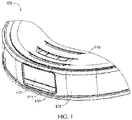
FIG. 1 illustrates a schematic stereoscopic diagram of a part of an intelligent cleaning apparatus according to an implementation of the present invention; -
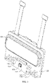
FIG. 2 illustrates a schematic cross-section diagram of a part of an intelligent cleaning apparatus illustrated inFIG. 1 ; -
FIG. 3 illustrates a schematic diagram of a mounting component for an illuminator and a camera illustrated inFIG. 2 ; and -
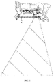
FIG. 4 is a schematic diagram of an illuminating scope of an illuminator illustrated inFIG. 2 . - List of reference numerals in the accompanying drawings:
- 100: Intelligent cleaning apparatus; 110: Device body;
- 121: Camera; 122: Camera support;
- 123: Camera cover; 124: Screw post;
- 125: Support wall; 126: Positioning post;
- 131: Illuminator; 132: Illuminator support;
- 133: Illuminator cover; 134: Screw hole;
- 135: Positioning hole; 140: Mounting component;
- 141: Photography opening; 142: Illuminator opening;
- 150: Bumper; and 151: Mounting opening.
- In the following descriptions, many specific details are provided for more thorough understanding of the present invention. However, it can be easily understood by those skilled in the art that, the present invention can be implemented without one or more of the details. In other examples, to avoid confusion with the present invention, some technical features commonly known in the art are not described.
- For thorough understanding of the present invention, the following descriptions provide detailed structures to facilitate illustration of the present invention. Clearly, embodiments of the present invention are not limited to specific details well known to those skilled in the art. Detailed descriptions of preferred implementations of the present invention are as follows. However, apart from the detailed descriptions, there may further be other implementations in the present invention. The present invention cannot be construed to be limited to implementations provided in this specification.
- It should be understood that, terms used in this specification are merely for describing specific implementations, and are not intended to limit the present invention. "A", "one" and "the" used with a singular form further imply and include a plural form, unless stated clearly otherwise in the context. When terms "include" and/or "comprise" are used in this specification, the terms indicate clearly the presence of the mentioned features, entirety, steps, operations, elements and/or components, but it is not excluded presence or addition of one or more other features, entirety, steps, operations, elements, components, and/or a combination thereof. Terms "above", "below", "front", "rear", "left", "right", and similar expressions used in the present invention are merely for description without limitation.
- Ordinal numbers such as "first' and "second" used in the present invention are merely for indication, but do not have any other meaning, for example, a specific sequence. In addition, for example, a term "first component" does not suggest that there is a "second component", and the term "second component" does not suggest that there is the "first component".
- The specific implementations of the present invention will be described hereinafter in details with reference to the accompanying drawings. The accompanying drawings illustrate representative implementations of the present invention, but are not intended to limit the present invention.
- Typically, an intelligent cleaning apparatus mainly includes a device body. The device body has a shape similar to a circle (and both a front side and a rear side are circular), or has other shape. It could be understood that, an intelligent cleaning apparatus illustrated in the present invention may be a sweeping robot, a mopping robot, a sweeping-mopping robot, or the like.
- The intelligent cleaning apparatus includes a cleaning system, a sensing system, a control system, a drive system, an energy system, a human-machine interaction system, and the like. The systems cooperate and coordinate with each other, so that the intelligent cleaning apparatus can move autonomously, to perform cleaning. Functional elements and the like for forming the foregoing systems of the intelligent cleaning apparatus are integrated and disposed on the device body. The device body includes an upper cover, a chassis, and a middle frame disposed between the upper cover and the chassis. The middle frame is configured as a basic framework for disposing the various functional elements. The upper cover and the chassis cover surfaces of the device body, so as to protect internal components and parts and improve ornamentality of the intelligent cleaning apparatus.
- The sensing system is configured for the intelligent cleaning apparatus to sense an external environment such as topography, and includes sensing devices such as a location determining device, a bumper, a cliff sensor, an ultrasonic sensor, an infrared sensor, a magnetometer, an accelerometer, a gyroscope, and an odograph. The sensing devices provide various location information and motion status information of the intelligent cleaning apparatus to the control system. The location determining device includes but is not limited to an infrared transmitting and receiving device, a camera, and a laser distance sensor (LDS). The bumper is configured to cushion a collision between the intelligent cleaning apparatus and a surrounding object during travelling. A layer of soft rubber is provided on a surface of the bumper, and the bumper is disposed at a preset distance from the device body when the bumper is mounted onto the device body, so that it is ensured that the device body can have enough time to decelerate when collision occurs.
- The control system is disposed on a circuit board on the device body. It should be understood that various control circuits configured to control the intelligent cleaning apparatus to operate are disposed on the circuit board. The control system includes a computing processor incommunication with a non-transitory memory. The computing processor may be a central processing unit, an application processor, or the like, and draws, based on obstacle information fed back by the laser distance sensor and through a locating algorithm, a real-time map of an environment that the intelligent cleaning apparatus is located in. In addition, the computing processor comprehensively determines, based on distance information and speed information fed back by the bumper and the sensing devices, an operation status of the intelligent cleaning apparatus, for example, crossing a doorsill, getting on a carpet, or being located at a steep, being stuck at a lower part or at an upper part, a dust box of the intelligent cleaning apparatus being full, or the intelligent cleaning apparatus being picked up. And the computing processor provides a specific strategy for a next action for different cases, so that services of the intelligent cleaning apparatus satisfy the requirement of a user better, thereby improving user experience.
- The human-machine interaction system includes a button on a main body panel, wherein the button is configured for a user to select a function; further includes a display and/or an indicating light and/or a speaker, wherein the display, the indicating light, and the speaker show the user a current status of the machine or selection of a function. The human-machine interaction system further includes a mobile phone client application. For a path navigation intelligent cleaning apparatus, a map of an environment that the device is located in and a location of the intelligent cleaning apparatus can be displayed to the user on a mobile phone client, and more and more user-friendly function items can be offered to the user.
- The energy system is configured to supply power to the functional elements of the systems for working, and mainly includes a rechargeable battery and a power supply circuit. The rechargeable battery may be a nickel-hydrogen battery or a lithium battery. When a power of the rechargeable battery is less than a preset minimum power, the rechargeable battery may be connected to a charging device through a recharging electrode disposed at a lateral side or a lower side of the device body.
- The cleaning system that is the most important core system of the intelligent cleaning apparatus, is configured to perform cleaning, and includes a dry cleaning part and a wet cleaning part. The dry cleaning part mainly cleans solid particle contaminants on a surface to be cleaned through a structure such as a cleaning brush, and the wet cleaning part mainly wipes the surface to be cleaned (for example, a floor) through a cleaning cloth with a cleaning liquid.
- The dry cleaning part mainly includes a cleaning assembly, a dust box and a fan. A primary brush of the cleaning assembly can sweep trash. The fan is communicated with the dust box through a wind channel, and the fan is configured to generate wind required for collecting dust. Specifically, as the intelligent cleaning apparatus moves, the primary brush that interfere with the floor to some extent sweeps the trash on the floor and takes the trash to a front side of a dust collection port between the primary brush and the dust box, and then the trash is suctioned into the dust box by air with suction force that is generated by the fan and passes through the dust box.
- The wet cleaning part mainly includes a liquid storage box and the cleaning cloth. The liquid storage box of the wet cleaning part stores the cleaning liquid, and the cleaning cloth is detachably disposed on the liquid storage box. After the dry cleaning part finishes cleaning, the cleaning liquid flows from the liquid storage box of the wet cleaning part to the cleaning cloth, and the cleaning cloth is configured to wipe a floor having cleaned by the primary brush and the like.
- The dry cleaning part may further include a side brush. The side brush is mounted to the device body through a rotating shaft. Specifically, the side brush is mounted at an edge of the device body from a bottom of the device body through the rotating shaft. The side brush can rotate around a rotation axis of the rotating shaft with respect to the device body, to move small pieces of trash (for example, debris or hairs) into a cleaning area of the primary brush.
- An
intelligent cleaning apparatus 100 according to an implementation of the present invention will be described hereinafter with reference toFIG. 1 to FIG. 4 . Theintelligent cleaning apparatus 100 according to the present invention has structures/configuration and functions of the foregoing parts. For brevity, details thereof will not be elaborated here. Theintelligent cleaning apparatus 100 further includes anilluminator 131, configured to increase light intensity in an environment, and specifically configured to increase light intensity in a recognition area of acamera 121. - As illustrated in
FIG. 1 andFIG. 2 , thecamera 121 is disposed on adevice body 110 and is oriented toward outside of thedevice body 110, and is configured to pick up an image of the environment, to perform functions of object recognition, navigation, locating, and the like. Theilluminator 131 is also disposed on thedevice body 110 and is oriented toward outside of thedevice body 110. Specifically, both thecamera 121 and theilluminator 131 are disposed at a front end of thedevice body 110 based on an advancing direction, so that thecamera 121 can pick up an image when theintelligent cleaning apparatus 100 moves forward. An illuminating direction of theilluminator 131 is substantially the same as an image-picking-up direction of thecamera 121, so that at least part of the recognition area of thecamera 121 is illuminated. - In this implementation, the light intensity in the recognition area of
camera 121 is increased by light emitted by theilluminator 131, so that thecamera 121 can pick up a required image, and theintelligent cleaning apparatus 100 can perform functions of object recognition, navigation, locating, and the like in a case of poor intensity of ambient light. In addition, thecamera 121 and theilluminator 131 are disposed on thedevice body 110, so that thecamera 121 and theilluminator 131 can be protected, and thecamera 121 and theilluminator 131 are avoided to be easily bumped and damaged due to exposure to the outside, thereby reducing material and labor costs for maintaining thecamera 121 and theilluminator 131. - As illustrated in
FIG. 2 andFIG. 3 , anilluminator support 132 is disposed on thedevice body 110. Theilluminator 131 can be mounted onto theilluminator support 132. In other words, theilluminator 131 is mounted on thedevice body 110 through the illuminator support. Theilluminator 131 may be fixed on theilluminator support 132 by welding. In the implementation illustrated in the drawings, theilluminator support 132 has a long stripe shape. Theilluminator 131 is disposed at a middle portion of theilluminator support 132. - In this implementation, a quantity of the
camera 121 and a quantity of theilluminators 131 are not limited. In the implementation illustrated in the drawings, theintelligent cleaning apparatus 100 includes twocameras 121 and oneilluminator 131. The twocameras 121 may be disposed horizontally, and a projection of theilluminator 131 on a horizontal plane may be located between projections of the twocameras 121 on the horizontal plane. Therefore, the oneilluminator 131 can be configured for both of the twocameras 121, to ensure the entire recognition area of the twocameras 121 can have supplementary light. - Although one
illuminator 131 is illustrated in the drawings, if required and/or desired, more than oneilluminator 131 may be disposed based on the quantity of thecameras 121. Theilluminator 131 may be located above or below thecamera 121. Preferably, theilluminator 131 is located below thecamera 121. Theilluminator 131 may be an infrared lamp. Theilluminator 131 may be a surface mounted lamp. Optionally, theilluminator 131 may be a surface mounted infrared lamp. Theilluminator support 132 is a printed circuit board (PCB). - The
illuminator 131 and thecamera 121 are disposed apart, and theilluminator 131 is disposed below thecamera 121. In this implementation, acamera support 122 is disposed on thedevice body 110. Thecamera 121 is mounted on thedevice body 110 through thecamera support 122. Theilluminator support 132 may be directly connected to thecamera support 122. In this implementation, no additional mounting component or structure is required, thereby avoiding an increase in a size of the device. In addition, a space in the structure of thecamera support 122 may be used to mount theilluminator 131, to improve utilization of an internal space of the intelligent cleaning apparatus. - The
illuminator support 132 may be detachably connected to thecamera support 122 through a fastening member such as a bolt. Specifically, in the implementation illustrated in the drawings, theilluminator support 132 may be provided with ascrew hole 134, and thecamera support 122 may be provided with ascrew post 124. Thescrew post 124 corresponds to thescrew hole 134 in a one-to-one correspondence. A bolt can pass through and be fastened to thescrew hole 134 and thescrew post 124, to fix theilluminator support 132 on thecamera support 122. That is, theilluminator support 132 can be mounted onto thecamera support 122 by screwing a bolt into thescrew hole 134 and thescrew post 124. Thescrew hole 134 may be disposed at two ends of theilluminator support 132. - To facilitate fitting and provide fastness of the
illuminator support 132, theilluminator support 132 may further be provided with apositioning hole 135. Thecamera support 122 is provided with asupport wall 125 having apositioning post 126. Thesupport wall 125 corresponds to thepositioning hole 135 in a one-to-one correspondence. Thesupport wall 125 can abut against theilluminator support 132, and thepositioning post 126 passes through thepositioning hole 135 so as to position theilluminator support 132. That is, theilluminator support 132 is fixed on thecamera support 122 by abutting thesupport wall 125 against theilluminator support 132 and getting thepositioning post 126 through thepositioning hole 135. Thepositioning hole 135 may also be disposed at the two ends of theilluminator support 132. - A circuit board is disposed on the
device body 110. Theilluminator support 132 is electrically connected to the circuit board through a flexible flat cable, to supply power to theilluminator 131. A control system on the circuit board is configured to selectively turn on or turn off theilluminator 131 based on intensity of ambient light detected by thecamera 121. Specifically, when insufficient or weak intensity of ambient light is detected and theilluminator 131 is required to be turned on, the control system sends a turn-on instruction to theilluminator support 132, and theilluminator support 132 supplies power to theilluminator 131. When intensity of ambient light that satisfies an image-picking-up requirement is detected and no illuminator is required, the control system sends a turn-off instruction to theilluminator support 132, and theilluminator support 132 stops supplying power to theilluminator 131. - A mounting
component 140 is disposed outside of thedevice body 110, wherein the mountingcomponent 140 may be provided with aphotography opening 141. Thephotography opening 141 is located at a position outside of thecamera 121 corresponding to a position of thecamera 121.Camera cover 123 is disposed on thedevice body 110, and thecamera cover 123 is located in front of thecamera 121 so as to protect thecamera 121. Thecamera cover 123 is disposed at thephotography opening 141. Thecamera 121 can pick up an image through thecamera cover 123. For the implementation illustrated in the drawings, thephotography opening 141 is a stepped ring opening, and thecamera cover 123 is mounted on a step of the stepped ring opening with a largest diameter. For example, thecamera cover 123 can be adhered to an outward stepped ring surface. - The
illuminator 131 may be located below thecamera 121. Correspondingly, anilluminator cover 133 may be located below thecamera cover 123, and theilluminator cover 133 and the forcamera cover 123 may have a same length. - The mounting
component 140 may further be provided with ailluminator opening 142, wherein theilluminator opening 142 is located at a position outside of theilluminator 131 corresponding to a position of theilluminator 131. Light emitted by theilluminator 131 can pass through theilluminator opening 142. Theilluminator cover 133 is further disposed on thedevice body 110, and theilluminator cover 133 is located in front of theilluminator 131 so as to protect theilluminator 131. Theilluminator cover 133 is made of a material transparent to the light emitted by theilluminator 131. For example, in an implementation in which theilluminator 131 is an infrared lamp, theilluminator cover 133 is made of a material transparent to infrared light. Theilluminator cover 133 is disposed at theilluminator opening 142. In other words, theilluminator opening 142 is provided with theilluminator cover 133. For the implementation illustrated in the drawings, theilluminator opening 142 is a stepped ring opening, and theilluminator cover 133 is mounted at a step of the stepped ring opening with a largest diameter. For example, theilluminator cover 133 can be adhered to an outward stepped ring surface. - In this implementation, both the
camera cover 123 and theilluminator cover 133 are fixed by the mountingcomponent 140. This can simplify structures and make assembling simple and easy. - Referring to
FIG. 4, FIG. 4 illustrates an example of an illuminating area of theilluminator 131. In this implementation, theintelligent cleaning apparatus 100 is configured so that light emitted by theilluminator 131 and passing through theilluminator opening 142 illuminates at least part of a recognition area of theilluminator 131, and preferably illuminates the entire recognition area. Further, a diameter of theilluminator opening 142 is designed to make the recognition area of theilluminator 131 taken from an environment is located within an area illuminated by the light of theilluminator 131 in this environment. - The
intelligent cleaning apparatus 100 further includes abumper 150. Thebumper 150 can be disposed around thedevice body 110 and is connected to thedevice body 110. Thebumper 150 is configured to cushion a collision between theintelligent cleaning apparatus 100 and a surrounding object during travelling. Both thecamera 121 and theilluminator 131 are disposed around thedevice body 110 and at an inner side of thebumper 150. In this way, thebumper 150 can protect thecamera 121 and the illuminator 131 from being damaged due to collision. - The mounting
component 140 can be mounted onto thebumper 150. Specifically, referring toFIG. 2 , thebumper 150 is provided with a mountingopening 151, and the mountingcomponent 140 is disposed in the mountingopening 151 and is fixed on thebumper 150, and specifically, is fixed at an edge of thebumper 150 at the mountingopening 151. Optionally, the mountingcomponent 140 may be mounted onto thebumper 150 through a fastening member such as a bolt, and/or mounted onto thebumper 150 through a clamping structure. - The intelligent cleaning apparatus according to the present invention resolves a problem in the conventional technology that a camera cannot pick up an image or picks up an unclear image due to an environmental factor. The intelligent cleaning apparatus according to the present invention can enable a camera to pick up an image with a required brightness, so that the intelligent cleaning apparatus performs accurately functions of object identification, navigation, locating, and the like, thereby improving a capability of the intelligent cleaning apparatus to sense an external environment such as topography and an obstacle and a capability of the intelligent cleaning apparatus to control the operation status of the intelligent cleaning apparatus.
- The camera and the illuminator are disposed on the device body, so that the camera and the illuminator can be protected, and the camera and the illuminator are kept from being easily bumped and damaged due to exposure to the outside, thereby reducing material and labor costs for maintaining the camera and the illuminator.
- Unless defined otherwise, technical and scientific terms used in this specification have same meanings as those usually understood by those skilled in the art of the present invention. Terms used in this specification are merely for purpose of describing a specific implementation objective, but are not intended to limit the present invention. Terms such as "component" and "part" in this specification may indicate a single component or part, and may indicate a combination of a plurality of components or parts. Terms such as "mount" and "dispose" in this specification may indicate that one component or part is directly attached to another component or part, and may indicate that one component or part is attached to another component or part via an intermediate component or part. In this specification, a feature described in one implementation may be applied to another implementation independently or in combination with another feature, unless the feature is not applicable in other implementation or it is stated otherwise.
- The present invention is described by taking the foregoing implementations as examples, but it should be understood that, the foregoing implementations are merely for taking examples and description, and are not intended to limit the present invention to a scope of the described implementations. In addition, it could be understood by those skilled in the art that, the present invention is not limited to the foregoing implementations. More variations and changes can be made according to teaching of the present invention, and all the variations and changes fall within a protection scope of the present invention. The protection scope of the present invention shall be defined according to the appended claims and an equivalent scope thereof.
Claims (11)
- An intelligent cleaning apparatus, characterized by comprising:a device body;a camera, wherein the camera is mounted on the device body and is oriented outside of the device body; andan illuminator, wherein the illuminator is mounted on the device body through an illuminator support and is oriented outside of the device body, and an illuminating direction of the illuminator is the same as an image-picking-up direction of the camera, so that at least part of a recognition area of the camera is illuminated.
- The intelligent cleaning apparatus according to claim 1, characterized in that a mounting component is disposed outside of the device body, the mounting component is provided with an illuminator opening, the illuminator opening is located in front of the illuminator, and the intelligent cleaning apparatus is configured so that light emitted by the illuminator and passing through the illuminator opening illuminates the at least part of the recognition area of the camera.
- The intelligent cleaning apparatus according to claim 2, characterized in that an illuminator cover is disposed at the illuminator opening, and the illuminator cover is made of a material transparent to the light emitted by the illuminator.
- The intelligent cleaning apparatus according to claim 3, characterized in that the mounting component is further provided with a photography opening, the photography opening is located outside of the camera, a camera cover is disposed at the photography opening, and the camera picks up an image through the camera cover.
- The intelligent cleaning apparatus according to claim 4, characterized in that the illuminator cover is located below the camera cover, and the illuminator cover and the camera cover have a same length.
- The intelligent cleaning apparatus according to any one of claims 2 to 5, characterized by further comprising a bumper disposed around the device body and connected to the device body, wherein the bumper is provided with a mounting opening, and the mounting component is located in the mounting opening and is fixed on the bumper.
- The intelligent cleaning apparatus according to claim 1, characterized in that the camera is fixed on the device body through a camera support, and the illuminator support is provided with a screw hole, the camera support is disposed with a screw post, and the illuminator support is mounted onto the camera support through screwing a bolt into the screw hole and the screw post.
- The intelligent cleaning apparatus according to claim 1, characterized in that the camera is fixed on the device body through a camera support; and the illuminator support is provided with a positioning hole, the camera support is provided with a support wall having a positioning post, and the illuminator support is fixed on the camera support by abutting the support wall against the illuminator support and passing the positioning post through the positioning hole.
- The intelligent cleaning apparatus according to claim 1, characterized by comprising two cameras and one illuminator, the two cameras are disposed horizontally, and a projection of the illuminator on a horizontal plane is located between projections of the two cameras on the horizontal plane.
- The intelligent cleaning apparatus according to claim 1, characterized in that the illuminator is an infrared illuminator, and/or the illuminator is a surface mounted illuminator, and the illuminator support is a PCB.
- The intelligent cleaning apparatus according to claim 1 or 10, characterized in that a circuit board is disposed on the device body, the illuminator support is electrically connected to the circuit board, and a control system on the circuit board is configured to selectively turn on or turn off the illuminator based on intensity of ambient light detected by the camera.
Applications Claiming Priority (2)
| Application Number | Priority Date | Filing Date | Title |
|---|---|---|---|
| CN202020056974.2U CN210927761U (en) | 2020-01-10 | 2020-01-10 | Intelligent cleaning equipment |
| PCT/CN2020/136583 WO2021139495A1 (en) | 2020-01-10 | 2020-12-15 | Intelligent cleaning device |
Publications (2)
| Publication Number | Publication Date |
|---|---|
| EP4089996A1 true EP4089996A1 (en) | 2022-11-16 |
| EP4089996A4 EP4089996A4 (en) | 2024-01-31 |
Family
ID=71351004
Family Applications (1)
| Application Number | Title | Priority Date | Filing Date |
|---|---|---|---|
| EP20912763.8A Pending EP4089996A4 (en) | 2020-01-10 | 2020-12-15 | Intelligent cleaning device |
Country Status (7)
| Country | Link |
|---|---|
| US (3) | US20220346617A1 (en) |
| EP (1) | EP4089996A4 (en) |
| KR (2) | KR20250073566A (en) |
| CN (2) | CN210927761U (en) |
| DE (1) | DE212020000803U1 (en) |
| TW (2) | TWI834941B (en) |
| WO (1) | WO2021139495A1 (en) |
Families Citing this family (13)
| Publication number | Priority date | Publication date | Assignee | Title |
|---|---|---|---|---|
| CN210927761U (en) * | 2020-01-10 | 2020-07-03 | 北京石头世纪科技股份有限公司 | Intelligent cleaning equipment |
| USD1003550S1 (en) * | 2020-09-03 | 2023-10-31 | Sharkninja Operating Llc | Robot vacuum wet module |
| CN112043209B (en) * | 2020-09-25 | 2025-09-16 | 苏州三六零机器人科技有限公司 | Laser module and robot sweeps floor |
| CN112168091B (en) * | 2020-09-25 | 2025-07-01 | 苏州三六零机器人科技有限公司 | Sweeping Robot |
| JP1747939S (en) * | 2021-02-10 | 2023-07-04 | Support plate for cleaning pad for robot vacuum cleaner | |
| USD1000741S1 (en) * | 2021-02-10 | 2023-10-03 | Beijing Roborock Technology Co., Ltd. | Water tank for a cleaning robot |
| CN113075692A (en) * | 2021-03-08 | 2021-07-06 | 北京石头世纪科技股份有限公司 | Target detection and control method, system, device and storage medium |
| CN112909712A (en) * | 2021-03-08 | 2021-06-04 | 北京石头世纪科技股份有限公司 | Line laser module and self-moving equipment |
| CN112864778A (en) * | 2021-03-08 | 2021-05-28 | 北京石头世纪科技股份有限公司 | Line laser module and self-moving equipment |
| CN113031607A (en) * | 2021-03-08 | 2021-06-25 | 北京石头世纪科技股份有限公司 | self mobile device |
| TWD231050S (en) * | 2023-02-28 | 2024-05-01 | 大陸商北京石頭世紀科技股份有限公司 (中國大陸) | Cleaning robot |
| CN116235682A (en) * | 2023-03-08 | 2023-06-09 | 未岚大陆(北京)科技有限公司 | Vision Modules, Mounts and Mowers for Lawn Mowers |
| USD1056381S1 (en) | 2023-03-31 | 2024-12-31 | Emerson Electric Co. | Vacuum conduit including illumination device |
Family Cites Families (25)
| Publication number | Priority date | Publication date | Assignee | Title |
|---|---|---|---|---|
| ES2346343T3 (en) * | 2005-02-18 | 2010-10-14 | Irobot Corporation | AUTONOMOUS SURFACE CLEANING ROBOT FOR DRY AND WET CLEANING. |
| US20090141461A1 (en) * | 2007-11-30 | 2009-06-04 | Inventec Corporation | Circuit board position structure |
| KR20130119601A (en) * | 2012-04-24 | 2013-11-01 | 주식회사 와이즈오토모티브 | Apparatus for measuring distance with laser |
| KR102020210B1 (en) * | 2013-04-11 | 2019-11-05 | 삼성전자주식회사 | Sensor module and robot cleaner having the same |
| CN203828847U (en) * | 2014-03-04 | 2014-09-17 | 东北师范大学 | Cleaning robot |
| US10463219B2 (en) * | 2014-10-03 | 2019-11-05 | Makita Corporation | Self-propelled, dust-collecting robot |
| KR101706966B1 (en) | 2015-07-17 | 2017-02-15 | 엘지전자 주식회사 | Robot Cleaner |
| CN106443697A (en) * | 2015-08-06 | 2017-02-22 | 信泰光学(深圳)有限公司 | Self-propelled device and environment distance measuring device thereof |
| CN205336383U (en) * | 2015-11-18 | 2016-06-22 | 杭州信多达电器有限公司 | A binocular camera device for sweeping machine |
| CN105615778B (en) * | 2016-01-22 | 2017-12-22 | 杭州信多达电器有限公司 | Sweeper with infrared camera shooting function |
| TWI652034B (en) * | 2016-05-17 | 2019-03-01 | Lg電子股份有限公司 | Cleaning robot |
| US10481611B2 (en) * | 2016-05-20 | 2019-11-19 | Lg Electronics Inc. | Autonomous cleaner |
| JP7005521B2 (en) * | 2016-05-20 | 2022-01-21 | エルジー エレクトロニクス インコーポレイティド | Robot vacuum cleaner |
| US10575696B2 (en) * | 2016-07-13 | 2020-03-03 | Irobot Corporation | Autonomous robot auto-docking and energy management systems and methods |
| CN106725131A (en) * | 2016-11-29 | 2017-05-31 | 宁波菜鸟智能科技有限公司 | A kind of floor cleaning machine with camera function |
| CN117122247A (en) | 2017-04-01 | 2023-11-28 | 北京石头世纪科技股份有限公司 | Smart cleaning equipment |
| CN106821155B (en) * | 2017-04-01 | 2022-08-23 | 小狗电器互联网科技(北京)股份有限公司 | Image-controlled dust collection power sweeping robot and control method |
| CN107137026A (en) * | 2017-06-26 | 2017-09-08 | 深圳普思英察科技有限公司 | A kind of sweeping robot and its camera light-supplementing system, method |
| CN107175645A (en) * | 2017-07-05 | 2017-09-19 | 深圳悉罗机器人有限公司 | Mobile robot |
| GB2574418B (en) * | 2018-06-05 | 2022-08-31 | Dyson Technology Ltd | A mobile robot and method of controlling a mobile robot illumination system |
| JP6596631B1 (en) | 2018-06-28 | 2019-10-30 | 株式会社マゼックス | Unmanned aerial vehicle |
| CN209063102U (en) * | 2018-08-24 | 2019-07-05 | 科沃斯机器人股份有限公司 | Self-movement robot |
| CN210144601U (en) * | 2019-01-23 | 2020-03-17 | 北京石头世纪科技股份有限公司 | Automatic cleaning equipment |
| CN209595660U (en) * | 2019-01-30 | 2019-11-08 | 信利光电股份有限公司 | A kind of sweeping robot |
| CN210927761U (en) * | 2020-01-10 | 2020-07-03 | 北京石头世纪科技股份有限公司 | Intelligent cleaning equipment |
-
2020
- 2020-01-10 CN CN202020056974.2U patent/CN210927761U/en active Active
- 2020-12-15 KR KR1020257016303A patent/KR20250073566A/en active Pending
- 2020-12-15 EP EP20912763.8A patent/EP4089996A4/en active Pending
- 2020-12-15 DE DE212020000803.5U patent/DE212020000803U1/en active Active
- 2020-12-15 CN CN202080098412.7A patent/CN116034585A/en active Pending
- 2020-12-15 WO PCT/CN2020/136583 patent/WO2021139495A1/en not_active Ceased
- 2020-12-15 KR KR1020227027496A patent/KR20220124784A/en not_active Ceased
-
2021
- 2021-01-08 TW TW110100852A patent/TWI834941B/en active
- 2021-01-08 TW TW113104313A patent/TWI871909B/en active
-
2022
- 2022-07-08 US US17/811,356 patent/US20220346617A1/en not_active Abandoned
- 2022-10-11 US US18/045,495 patent/US11864699B2/en active Active
-
2023
- 2023-11-28 US US18/521,366 patent/US20240090730A1/en active Pending
Also Published As
| Publication number | Publication date |
|---|---|
| TW202127131A (en) | 2021-07-16 |
| US20240090730A1 (en) | 2024-03-21 |
| US20230066176A1 (en) | 2023-03-02 |
| WO2021139495A1 (en) | 2021-07-15 |
| TWI871909B (en) | 2025-02-01 |
| DE212020000803U1 (en) | 2022-10-10 |
| TW202427038A (en) | 2024-07-01 |
| CN210927761U (en) | 2020-07-03 |
| KR20250073566A (en) | 2025-05-27 |
| CN116034585A (en) | 2023-04-28 |
| US20220346617A1 (en) | 2022-11-03 |
| KR20220124784A (en) | 2022-09-14 |
| TWI834941B (en) | 2024-03-11 |
| US11864699B2 (en) | 2024-01-09 |
| EP4089996A4 (en) | 2024-01-31 |
Similar Documents
| Publication | Publication Date | Title |
|---|---|---|
| US11864699B2 (en) | Cleaning device | |
| AU2016372758B2 (en) | Automatic cleaning device and cleaning method | |
| EP4505927A1 (en) | Automatic cleaning devices, control method and storage medium | |
| CN104055462A (en) | Robot Cleaner And Method Of Operating The Same | |
| JP2019091326A (en) | Cleaning system, robot cleaning device comprising cleaning system, and flying object device | |
| US10646090B2 (en) | Cleaning robot | |
| US20240341551A1 (en) | Intelligent cleaning device | |
| JP2019202160A (en) | Cleaning system and robot cleaning device constituting cleaning system, and flight body device | |
| EP4464220A1 (en) | Automatic cleaning apparatus | |
| EP4684716A1 (en) | Cleaning robot system | |
| KR102306436B1 (en) | Moving Robot and controlling method | |
| CN211022469U (en) | Floor sweeping robot | |
| AU2024202597B2 (en) | Cleaning device | |
| CN114829085B (en) | Mobile robot and control method thereof | |
| KR20120125085A (en) | Mobile robot | |
| CN217365667U (en) | Automatic cleaning equipment | |
| CN215942902U (en) | Robot | |
| JP2019185500A (en) | Autonomous vacuum cleaner | |
| CN207463778U (en) | Intelligent cleaning equipment | |
| EA046131B1 (en) | INTELLIGENT CLEANING EQUIPMENT | |
| JP7134075B2 (en) | Autonomous cleaning device | |
| EA049088B1 (en) | CLEANING EQUIPMENT |
Legal Events
| Date | Code | Title | Description |
|---|---|---|---|
| STAA | Information on the status of an ep patent application or granted ep patent |
Free format text: STATUS: THE INTERNATIONAL PUBLICATION HAS BEEN MADE |
|
| PUAI | Public reference made under article 153(3) epc to a published international application that has entered the european phase |
Free format text: ORIGINAL CODE: 0009012 |
|
| STAA | Information on the status of an ep patent application or granted ep patent |
Free format text: STATUS: REQUEST FOR EXAMINATION WAS MADE |
|
| 17P | Request for examination filed |
Effective date: 20220804 |
|
| AK | Designated contracting states |
Kind code of ref document: A1 Designated state(s): AL AT BE BG CH CY CZ DE DK EE ES FI FR GB GR HR HU IE IS IT LI LT LU LV MC MK MT NL NO PL PT RO RS SE SI SK SM TR |
|
| DAV | Request for validation of the european patent (deleted) | ||
| DAX | Request for extension of the european patent (deleted) | ||
| REG | Reference to a national code |
Ref country code: DE Ref legal event code: R079 Free format text: PREVIOUS MAIN CLASS: H04N0005225000 Ipc: A47L0011400000 |
|
| A4 | Supplementary search report drawn up and despatched |
Effective date: 20240105 |
|
| RIC1 | Information provided on ipc code assigned before grant |
Ipc: G03B 17/56 20210101ALI20231222BHEP Ipc: G05D 1/02 20200101ALI20231222BHEP Ipc: F21V 33/00 20060101ALI20231222BHEP Ipc: A47L 11/40 20060101AFI20231222BHEP |
|
| STAA | Information on the status of an ep patent application or granted ep patent |
Free format text: STATUS: EXAMINATION IS IN PROGRESS |
|
| 17Q | First examination report despatched |
Effective date: 20251120 |