EP4089985A1 - Electronic device, photographing method, and photographing apparatus - Google Patents
Electronic device, photographing method, and photographing apparatus Download PDFInfo
- Publication number
- EP4089985A1 EP4089985A1 EP20911679.7A EP20911679A EP4089985A1 EP 4089985 A1 EP4089985 A1 EP 4089985A1 EP 20911679 A EP20911679 A EP 20911679A EP 4089985 A1 EP4089985 A1 EP 4089985A1
- Authority
- EP
- European Patent Office
- Prior art keywords
- arc
- shaped surface
- camera
- electronic device
- drive
- Prior art date
- Legal status (The legal status is an assumption and is not a legal conclusion. Google has not performed a legal analysis and makes no representation as to the accuracy of the status listed.)
- Pending
Links
Images




Classifications
-
- H—ELECTRICITY
- H04—ELECTRIC COMMUNICATION TECHNIQUE
- H04M—TELEPHONIC COMMUNICATION
- H04M1/00—Substation equipment, e.g. for use by subscribers
- H04M1/02—Constructional features of telephone sets
- H04M1/0202—Portable telephone sets, e.g. cordless phones, mobile phones or bar type handsets
- H04M1/026—Details of the structure or mounting of specific components
-
- H—ELECTRICITY
- H04—ELECTRIC COMMUNICATION TECHNIQUE
- H04M—TELEPHONIC COMMUNICATION
- H04M1/00—Substation equipment, e.g. for use by subscribers
- H04M1/02—Constructional features of telephone sets
- H04M1/0202—Portable telephone sets, e.g. cordless phones, mobile phones or bar type handsets
- H04M1/026—Details of the structure or mounting of specific components
- H04M1/0264—Details of the structure or mounting of specific components for a camera module assembly
-
- H—ELECTRICITY
- H04—ELECTRIC COMMUNICATION TECHNIQUE
- H04N—PICTORIAL COMMUNICATION, e.g. TELEVISION
- H04N23/00—Cameras or camera modules comprising electronic image sensors; Control thereof
- H04N23/50—Constructional details
- H04N23/54—Mounting of pick-up tubes, electronic image sensors, deviation or focusing coils
-
- G—PHYSICS
- G03—PHOTOGRAPHY; CINEMATOGRAPHY; ANALOGOUS TECHNIQUES USING WAVES OTHER THAN OPTICAL WAVES; ELECTROGRAPHY; HOLOGRAPHY
- G03B—APPARATUS OR ARRANGEMENTS FOR TAKING PHOTOGRAPHS OR FOR PROJECTING OR VIEWING THEM; APPARATUS OR ARRANGEMENTS EMPLOYING ANALOGOUS TECHNIQUES USING WAVES OTHER THAN OPTICAL WAVES; ACCESSORIES THEREFOR
- G03B37/00—Panoramic or wide-screen photography; Photographing extended surfaces, e.g. for surveying; Photographing internal surfaces, e.g. of pipe
- G03B37/02—Panoramic or wide-screen photography; Photographing extended surfaces, e.g. for surveying; Photographing internal surfaces, e.g. of pipe with scanning movement of lens or cameras
-
- H—ELECTRICITY
- H04—ELECTRIC COMMUNICATION TECHNIQUE
- H04N—PICTORIAL COMMUNICATION, e.g. TELEVISION
- H04N23/00—Cameras or camera modules comprising electronic image sensors; Control thereof
- H04N23/50—Constructional details
- H04N23/53—Constructional details of electronic viewfinders, e.g. rotatable or detachable
-
- H—ELECTRICITY
- H04—ELECTRIC COMMUNICATION TECHNIQUE
- H04N—PICTORIAL COMMUNICATION, e.g. TELEVISION
- H04N23/00—Cameras or camera modules comprising electronic image sensors; Control thereof
- H04N23/57—Mechanical or electrical details of cameras or camera modules specially adapted for being embedded in other devices
-
- H—ELECTRICITY
- H04—ELECTRIC COMMUNICATION TECHNIQUE
- H04N—PICTORIAL COMMUNICATION, e.g. TELEVISION
- H04N23/00—Cameras or camera modules comprising electronic image sensors; Control thereof
- H04N23/60—Control of cameras or camera modules
- H04N23/695—Control of camera direction for changing a field of view, e.g. pan, tilt or based on tracking of objects
-
- H—ELECTRICITY
- H04—ELECTRIC COMMUNICATION TECHNIQUE
- H04N—PICTORIAL COMMUNICATION, e.g. TELEVISION
- H04N23/00—Cameras or camera modules comprising electronic image sensors; Control thereof
- H04N23/60—Control of cameras or camera modules
- H04N23/698—Control of cameras or camera modules for achieving an enlarged field of view, e.g. panoramic image capture
-
- H—ELECTRICITY
- H04—ELECTRIC COMMUNICATION TECHNIQUE
- H04N—PICTORIAL COMMUNICATION, e.g. TELEVISION
- H04N23/00—Cameras or camera modules comprising electronic image sensors; Control thereof
- H04N23/80—Camera processing pipelines; Components thereof
-
- G—PHYSICS
- G03—PHOTOGRAPHY; CINEMATOGRAPHY; ANALOGOUS TECHNIQUES USING WAVES OTHER THAN OPTICAL WAVES; ELECTROGRAPHY; HOLOGRAPHY
- G03B—APPARATUS OR ARRANGEMENTS FOR TAKING PHOTOGRAPHS OR FOR PROJECTING OR VIEWING THEM; APPARATUS OR ARRANGEMENTS EMPLOYING ANALOGOUS TECHNIQUES USING WAVES OTHER THAN OPTICAL WAVES; ACCESSORIES THEREFOR
- G03B30/00—Camera modules comprising integrated lens units and imaging units, specially adapted for being embedded in other devices, e.g. mobile phones or vehicles
-
- H—ELECTRICITY
- H04—ELECTRIC COMMUNICATION TECHNIQUE
- H04M—TELEPHONIC COMMUNICATION
- H04M2250/00—Details of telephonic subscriber devices
- H04M2250/20—Details of telephonic subscriber devices including a rotatable camera
Definitions
- the present invention relates to the field of communications technologies, and in particular, to an electronic device, a photographing method, and a photographing apparatus.
- a wide-angle camera is used as an auxiliary, and a software algorithm is also used to increase the shooting angle of the camera.
- the wide-angle camera is expensive, which increases the cost of the mobile terminal.
- Embodiments of the present invention provide an electronic device, a photographing method, and a photographing apparatus to solve the problem of the increased cost of the mobile terminal caused by using a wide-angle camera to increase the photographing angle in the related art.
- the present invention is implemented as follows:
- the embodiments of the present invention provide an electronic device, where the electronic device includes a camera, a main body portion, a connecting rod, and a driving mechanism;
- the embodiments of the present invention further provide a photographing method, applied to an electronic device, where the electronic device includes a main body portion and a camera, a rear face of the camera is provided with a first arc-shaped surface that protrudes in a direction away from the camera, the main body portion is provided with a second arc-shaped surface that matches and is slidably connected to the first arc-shaped surface, and the method includes:
- the embodiments of the present invention further provide a photographing apparatus, applied to an electronic device, where the electronic device includes a main body portion and a camera, a rear face of the camera is provided with a first arc-shaped surface that protrudes in a direction away from the camera, the main body portion is provided with a second arc-shaped surface that is slidably connected to the first arc-shaped surface, and the apparatus includes:
- the embodiments of the present invention further provide an electronic device, including a memory, a processor, and a computer program stored in the memory and executable on the processor, where when the computer program is executed by the processor, the steps of the photographing method provided in the second aspect of the embodiments of the present invention are implemented.
- the embodiments of the present invention further provide a computer readable storage medium.
- the computer readable storage medium stores a computer program, and when the computer program is executed by a processor, the steps of the photographing method provided in the second aspect of the embodiments of the present invention are implemented.
- the electronic device includes a camera, a main body portion, a connecting rod, and a driving mechanism; a rear face of the camera is provided with a first arc-shaped surface that protrudes in a direction away from the camera, the main body portion is provided with a second arc-shaped surface that matches and is slidably connected to the first arc-shaped surface, and the second arc-shaped surface is provided with a through hole; the connecting rod penetrates through the through hole, and a first end of the connecting rod is hinged to the first arc-shaped surface of the camera; and the driving mechanism is connected to a second end of the connecting rod, and is used to drive the connecting rod to drive the first arc-shaped surface to slide relative to the second arc-shaped surface, so as to drive the camera to rotate during a shooting process.
- the driving mechanism may drive the connecting rod to drive the first arc-shaped surface to slide relative to the second arc-shaped surface, so as to change the shooting angle of the camera fixed on the first arc-shaped surface, and increase the shooting angle of the camera.
- the electronic device has a simple structure and low production cost.
- the electronic device provided in the embodiments of the present invention can drive the camera to rotate during the photographing process, so as to increase the shooting angle of the camera.
- the foregoing electronic device may be a mobile phone, a tablet personal computer (Tablet Personal Computer), a laptop computer (Laptop Computer), a personal digital assistant (personal digital assistant, PDA), a mobile Internet device (Mobile Internet Device, MID), a wearable device (Wearable Device), a computer, a notebook computer, or other electronic device with a camera.
- FIG. 1 is a schematic diagram of a first arc-shaped surface and a camera in an electronic device according to an embodiment of the present invention
- FIG. 2 is a schematic structural diagram of an electronic device according to an embodiment of the present invention.
- the electronic device includes a camera 10, a main body portion (not shown in the figure), a connecting rod 103, and a driving mechanism 104; a rear face of the camera 10 is provided with a first arc-shaped surface 101 that protrudes in a direction away from the camera 10, the main body portion is provided with a second arc-shaped surface 102 that matches and is slidably connected to the first arc-shaped surface 101, and the second arc-shaped surface 102 is provided with a through hole 1031, where the connecting rod 103 penetrates through the through hole 1021, and a first end of the connecting rod 103 is hinged to the first arc-shaped surface 101 of the camera 10; and the driving mechanism 104 is connected to a second end of the connecting rod 103, and is used to drive the connecting rod 103 to drive the first arc-shaped surface 101 to slide relative to the second arc-shaped surface 102, so as to drive the camera 10 to rotate during a shooting process.
- the driving mechanism 104 may be an electric motor, a motor, or other driving mechanism.
- the processor of the electronic device is connected to the driving mechanism 104 to control the driving mechanism 104 to drive the connecting rod 103 to move along a specific trajectory, and to synthesize photos taken during the movement into a wide-angle photo based on the moving trajectory.
- first arc-shaped surface 101 may be formed by a first connector that is fixedly connected to the rear face of the camera 10 and has a first arc-shaped surface.
- the second arc-shaped surface 102 may be formed by a second connector that is fixedly connected to the main body of the electronic device and has a second arc-shaped surface.
- the second arc-shaped surface 102 is fixed to the casing or the circuit board of the electronic device.
- the camera 10 may be movably installed on the electronic device through the first connector and the second connector, and can have a plurality of shooting angles relative to the electronic device, thereby increasing the shooting angle of the camera 10 on the electronic device.
- the first arc-shaped surface 101 may also be formed by the rear face of the camera 10 protruding in a direction away from the camera 10; and the second arc-shaped surface 102 may also be formed by the main body of the electronic device sinking in the direction away from the camera 10. This may reduce the quantity of the components of the electronic device, thereby reducing the cost of the electronic device and simplifying the structure and installation steps of the electronic device.
- the camera 10 is also electrically connected to the electronic device, so as to control the camera 10 through the input operation on the electronic device.
- the camera 10 is connected to the circuit board in the electronic device through a flexible printed circuit 20 and a connector 30.
- the processor on the electronic device controls the driving mechanism 104 to drive the connecting rod 103 to move, so as to drive the first arc-shaped surface 101 to move relative to the second arc-shaped surface 102, thereby increasing the field of view of the camera 10, and further increasing the shooting angle of the camera 10.
- a shooting angle A of the camera 10 is 60 degrees
- the camera 10 in an initial position as shown in FIG. 3 , the camera 10 only shoots a range of 60 degrees along its focal length axis.
- the focal length axis also rotates for 60 degrees from a direction of the second end 1023 to a direction of the first end 1022, so that when the shooting angle of the camera 10 covers the field of view during the movement, the angle B is 120 degrees.
- the camera may capture a plurality of images that may be synthesized in the electronic device, so as to synthesize the plurality of photos captured from different angles into a wide-angle photo.
- the specific synthesis steps and algorithms are conventional techniques in the field of photography, and details are not repeated herein again.
- the shooting angle of the camera is greatly increased by using the apparatus for increasing the shooting angle of the camera in this implementation.
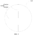
- the guide rail(s) 1024 communicated with the through hole 1021 is/are disposed through the second arc-shaped surface 102, and the driving mechanism 104 drives the connecting rod 103 to move along the guide rail(s) 1024.
- the guide rail(s) 1024 may extend in one direction or in a plurality of directions.
- the first guide rail 10241 and the second guide rail 10242 as shown in FIG. 5 , and in a specific application, the first guide rail 10241 extends horizontally along the electronic device, and the second guide rail 10242 extends longitudinally along the electronic device, so that the shooting angle along the horizontal and longitudinal directions of the electronic device may be increased more easily.
- the camera 10 may be controlled to move on the first guide rail 10241 extending horizontally along the electronic device, so as to increase the horizontal shooting angle of the camera 10.
- the camera 10 may be controlled to move on the second guide rail 10242 extending longitudinally along the electronic device, so as to increase the longitudinal shooting angle of the camera 10.
- the guide rail(s) 1024 may also be in a shape of an arc, for example, the arc guide rail(s) 1024 shown in FIG. 6 .
- the camera 10 rotates along the arc guide rail(s) 1024 relative to the main body of the electronic device, so that shooting angles of the camera 10 at every angle may be increased.
- the through hole 1021 may be any point on the arc guide rail(s) 1024.
- a through hole may also be opened at the center of the second arc-shaped surface 102, and a communication guide rail is opened on the second arc-shaped surface 102 to communicate the through hole and the arc guide rail(s) 1024, which is not specifically limited herein.
- a plane formed by the arc guide rail(s) 1024 is parallel to the rear face of the camera 10.
- all increased shooting angles of the camera in all directions may be the same, and the increased shooting angles of the camera in all directions are prevented from being different, which increases the difficulty of synthesizing photos, or causes disadvantages such as the synthesized picture to be deformed, thereby optimizing the shooting performance of the camera.
- the guide rail(s) 1024 may not be provided, but a hollow region (not shown in the figure) is formed in the center of the second arc-shaped surface 102, so that the second arc-shaped surface 102 is in an annular shape.
- the connecting rod 103 passes through the hollow region, and connects to the first arc-shaped surface 1 and the driving mechanism 104. Driven by the driving mechanism 104, the connecting rod 103 may swing in any direction in the hollow region, for example, swinging left and right, swinging up and down, swinging along an arc, and the like, which are not specifically limited herein.
- the shooting angle of the camera in any direction may be increased, and the shooting performance of the electronic device may be improved.
- the second arc-shaped surface covers only a first region of the first arc-shaped surface, where the first region is a region close to a center of the first arc-shaped surface.
- an edge of the camera 10 may extend to the outside of the first arc-shaped surface 101, and the second arc-shaped surface covers only the first region close to the center of the first arc-shaped surface.
- areas of the first arc-shaped surface 101 and the second arc-shaped surface 102 may further be increased, so that the camera 10 is fixed on a lower concave surface of the first arc-shaped surface 101.
- the first arc-shaped surface 101 may be made of the conductive material.
- the first arc-shaped surface 101 may also be made of a non-conductive material, which may be determined based on the grounding design of the electronic device, and is not specifically limited herein.
- the electronic device provided in the embodiments of the present invention includes a camera and a main body portion, where a rear face of the camera is provided with a first arc-shaped surface that protrudes in a direction away from the camera, the main body portion is provided with a second arc-shaped surface that matches and is slidably connected to the first arc-shaped surface, and the second arc-shaped surface is provided with a through hole; the electronic device further includes a connecting rod, the connecting rod penetrates through the through hole, and a first end of the connecting rod is hinged to the first arc-shaped surface of the camera; and a driving mechanism, the driving mechanism is connected to a second end of the connecting rod, and is used to drive the connecting rod to drive the first arc-shaped surface to slide relative to the second arc-shaped surface, so as to drive the camera to rotate during a shooting process.
- the driving mechanism may drive the connecting rod to move, to drive the first arc-shaped surface to move relative to the second arc-shaped surface, so as to change the shooting angle of the camera fixed on the first arc-shaped surface, and increase the shooting angle of the camera.
- the electronic device has a simple structure and low production cost.
- FIG. 7 is a flowchart of a shooting method according to an embodiment of the present invention.
- the method is applied to an electronic device, where the electronic device includes a main body portion and a camera, a rear face of the camera is provided with a first arc-shaped surface that protrudes in a direction away from the camera, and the main body portion is provided with a second arc-shaped surface that matches and is slidably connected to the first arc-shaped surface.
- the method includes the following steps.
- Step 701 Drive, in a case that the camera is started, the first arc-shaped surface to slide relative to the second arc-shaped surface, so as to drive the camera to rotate along a preset trajectory and capture images.
- the foregoing preset trajectory may be a trajectory of the guide rail(s) on the second arc-shaped surface, or may be a trajectory pre-stored in the electronic device, which is not specifically limited herein.
- Step 702 Display a target image, where the target image is obtained by synthesizing images captured by the camera.
- the target image is a synthesized wide-angle photo.
- the image information collected by the camera may be synthesized based on the preset trajectory to obtain target image information, and the target image is an image corresponding to the target image information.
- the image information captured in different moving trajectories may be corresponding to different synthesis parameters, such that the target image information corresponding to the moving trajectories may be obtained.
- the camera collects images at different positions on the preset trajectory. For example, in a case that the preset trajectory extends in a same direction, an image may be collected at an initial end of the preset trajectory, and another image may be collected at the end of the preset trajectory. Finally, these two images are synthesized into a wide-angle photo.
- the target image information covers a wider field of view, which can improve the performance of photography.
- the method before the driving, in a case that the camera is started, the first arc-shaped surface to slide relative to the second arc-shaped surface, so as to drive the camera to rotate along a preset trajectory and capture images, the method further includes:
- the receiving a first control instruction for enabling a wide-angle shooting mode may be receiving an operation that the user selects to enable the wide-angle shooting mode on the electronic device, or receiving a control instruction for enabling the wide-angle shooting mode sent by other devices other than the processor or the electronic device.
- the camera may perform shooting at the initial position, and a focal length direction of the camera in the initial position is perpendicular to the panel of the electronic device.
- the connecting rod may be driven to drive the camera fixed on the first arc-shaped surface to rotate along the preset trajectory, and in a case that the wide-angle shooting mode is not enabled, the camera may perform shooting at the initial position.
- this implementation may be used to reduce the resource waste of the photographing method.
- the method further includes: driving the first arc-shaped surface to slide relative to the second arc-shaped surface, so as to drive the camera to move to an initial position, where the camera in the initial position faces a direction perpendicular to a panel of the electronic device.
- That the camera faces a direction perpendicular to a panel of the electronic device described above may be understood as: the focal length direction of the camera is perpendicular to the panel of the electronic device.
- the camera may be returned to the initial position to prepare for the next shooting.
- the method before the driving, in a case that the camera is started, the first arc-shaped surface to slide relative to the second arc-shaped surface, so as to drive the camera to rotate along a preset trajectory and capture images, the method further includes:
- the camera in the process of shooting a same wide-angle image, the camera is turned to rotate in a same direction, so that a plurality of graphics obtained during the wide-angle shooting process of the camera are corresponding to the spatial order.
- the calculation difficulty of the synthesis is reduced, especially when there are moving objects in the shooting picture. This may reduce the cases that there is same moving object in photos taken at different times, and make it easier to synthesize the wide-angle photo.
- the preset trajectory further includes at least one of the following:
- first trajectory, second trajectory, and third trajectory are respectively corresponding to guide rails shown in FIG. 5 and FIG. 6 with same beneficial effects. Details are not described herein again.
- the apparatus on the electronic device can be controlled to increase the shooting angle of the camera, so as to take photos for the preset trajectory, and synthesize the photos into a wide-angle photo, so that the camera can have a wide-angle shooting function.
- the method has same beneficial effects as the apparatus used to increase the shooting angle of the camera provided in the embodiments of the present invention, and details are not repeated herein again.
- the embodiments of the present invention further provide a photographing apparatus 800, applied to an electronic device, where the electronic device includes a main body portion and a camera, a rear face of the camera is provided with a first arc-shaped surface that protrudes in a direction away from the camera, and the main body portion is provided with a second arc-shaped surface that is slidably connected to the first arc-shaped surface.
- the apparatus 800 includes:
- the apparatus 800 further includes:
- the apparatus 800 further includes: a second driver module 804, configured to drive the first arc-shaped surface to slide relative to the second arc-shaped surface, so as to drive the camera to move to an initial position, where the camera in the initial position faces a direction perpendicular to a panel of the electronic device.
- a second driver module 804 configured to drive the first arc-shaped surface to slide relative to the second arc-shaped surface, so as to drive the camera to move to an initial position, where the camera in the initial position faces a direction perpendicular to a panel of the electronic device.
- the apparatus 800 further includes:
- the preset trajectory further includes at least one of the following:
- the photographing apparatus provided in the embodiments of the present invention can perform each process of the photographing method provided in the embodiments of the present invention, and can achieve same beneficial effects. To avoid repetition, details are not repeated herein again.
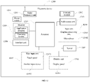
- FIG. 12 is a schematic structural diagram of hardware of an electronic device according to the embodiments of the present invention.
- the electronic device 1200 includes but is not limited to components such as a radio frequency unit 1201, a network module 1202, an audio output unit 1203, an input unit 1204, a sensor 1205, a display unit 1206, a user input unit 1207, an interface unit 1208, a memory 1209, a processor 1210, and a power supply 1211.
- a radio frequency unit 1201 such as a radio frequency unit 1201, a network module 1202, an audio output unit 1203, an input unit 1204, a sensor 1205, a display unit 1206, a user input unit 1207, an interface unit 1208, a memory 1209, a processor 1210, and a power supply 1211.
- a structure of the electronic device shown in FIG. 12 constitutes no limitation on the electronic device, and the electronic device may include more or fewer components than those shown in the figure, or have a combination of some components, or have a different component arrangement.
- the electronic device includes but is not limited to a mobile phone, a tablet computer, a notebook computer, a palmtop computer, an in-vehicle terminal, a wearable device, a pedometer, a computer, and the like.
- the processor 1210 is configured to: drive, in a case that the camera is started, the first arc-shaped surface to slide relative to the second arc-shaped surface, so as to drive the camera to rotate along a preset trajectory and capture images; and the display unit 1206 is configured to display a target image, where the target image is obtained by synthesizing images captured by the camera.
- the user input unit 1207 is configured to receive a first control instruction for enabling a wide-angle shooting mode, where the processor 1210 is further configured to start, in response to the first control instruction, the camera, and drive the first arc-shaped surface to slide relative to the second arc-shaped surface, so as to drive the camera to rotate along the preset trajectory and capture images.
- the processor 1210 is further configured to drive the first arc-shaped surface to slide relative to the second arc-shaped surface, so as to drive the camera to move to an initial position, where the camera in the initial position faces a direction perpendicular to a display panel of the electronic device.
- the preset trajectory further includes at least one of the following:
- the electronic device 1200 provided in the embodiments of the present invention may control the camera installed on it to rotate during the shooting process, so as to take photos for the preset trajectory, and synthesize them into a wide-angle photo, so that the camera can have a wide-angle shooting function.
- the electronic device has same beneficial effects as the electronic device provided in any of the embodiments from FIG. 1 to FIG. 6 , and details are not repeated herein again.
- the radio frequency unit 1201 may be configured to receive and send information or receive and send a signal in a call process. Specifically, after downlink data from a base station is received, the processor 1210 processes the downlink data. In addition, uplink data is sent to the base station.
- the radio frequency unit 1201 includes but is not limited to an antenna, at least one amplifier, a transceiver, a coupler, a low noise amplifier, a duplexer, and the like.
- the radio frequency unit 1201 may communicate with a network and another device through a wireless communication system.
- the electronic device provides wireless broadband Internet access for the user by using the network module 1202, for example, helping the user to send and receive an e-mail, brows a web page, and access streaming media.
- the audio output unit 1203 may convert audio data received by the radio frequency unit 1201 or the network module 1202 or stored in the memory 1209 into an audio signal and output the audio signal as a sound.
- the audio output unit 1203 may further provide an audio output (for example, a call signal received voice, or a message received voice) related to a specific function implemented by the electronic device 1200.
- the audio output unit 1203 includes a speaker, a buzzer, a telephone receiver, and the like.
- the input unit 1204 is configured to receive an audio signal or a video signal.
- the input unit 1204 may include a graphics processing unit (Graphics Processing Unit, GPU) 12041 and a microphone 12042.
- the graphics processing unit 12041 processes image data of a static picture or a video obtained by an image capture apparatus (such as a camera) in a video capture mode or an image capture mode.
- a processed image frame may be displayed on the display unit 1206.
- the image frame processed by the graphics processing unit 12041 may be stored in the memory 1209 (or another storage medium) or sent by using the radio frequency unit 1201 or the network module 1202.
- the microphone 12042 may receive a sound and can process such sound into audio data. Processed audio data may be converted, in a call mode, into a format that can be sent to a mobile communication base station by using the radio frequency unit 1201 for output.
- the electronic device 1200 further includes at least one sensor 1205, for example, a light sensor, a motion sensor, and another sensor.
- the light sensor includes an ambient light sensor and a proximity sensor.
- the ambient light sensor may adjust luminance of the display panel 12061 based on brightness of ambient light.
- the proximity sensor may turn off the display panel 12061 and/or backlight when the electronic device 1200 moves to an ear.
- an accelerometer sensor may detect an acceleration value in each direction (generally, three axes), and detect a value and a direction of gravity when the accelerometer sensor is static, and may be used for recognizing a posture of the electronic device (such as screen switching between landscape and portrait modes, a related game, or magnetometer posture calibration), a function related to vibration recognition (such as a pedometer or a knock), and the like.
- the sensor 1205 may further include a fingerprint sensor, a pressure sensor, an iris sensor, a molecular sensor, a gyroscope, a barometer, a hygrometer, a thermometer, an infrared sensor, and the like. Details are not described herein.
- the display unit 1206 is configured to display information input by a user or information provided for a user.
- the display unit 1206 may include a display panel 12061.
- the display panel 12061 may be configured in a form of a liquid crystal display (Liquid Crystal Display, LCD), an organic light-emitting diode (Organic Light-Emitting Diode, OLED), or the like.
- the user input unit 1207 may be configured to: receive input digital or character information, and generate key signal input related to a user setting and function control of the electronic device.
- the user input unit 1207 includes a touch panel 12071 and another input device 12072.
- the touch panel 12071 is also referred to as a touchscreen, and may collect a touch operation of the user on or near the touch panel (for example, an operation performed on or near the touch panel 12071 by the user by using any appropriate object or accessory such as a finger or a stylus).
- the touch panel 12071 may include two parts: a touch detection apparatus and a touch controller.
- the touch detection apparatus detects a touch position of the user, detects a signal brought by the touch operation, and sends the signal to the touch controller.
- the touch controller receives touch information from the touch detection apparatus, converts the touch information into touch point coordinates, sends the touch point coordinates to the processor 1210, and receives and executes a command sent by the processor 1210.
- the touch panel 12071 may be implemented by using a plurality of types such as a resistive type, a capacitive type, an infrared ray, and a surface acoustic wave.
- the user input unit 1207 may include other input devices 12072 in addition to the touch panel 12071.
- the another input device 12072 may include but is not limited to: a physical keyboard, a function button (such as a volume control button, a switch button), a trackball, a mouse, and a joystick, which is not described herein.
- the touch panel 12071 may cover the display panel 12061.
- the touch panel 12071 transmits the touch operation to the processor 1210 to determine a type of a touch event, and then the processor 1210 provides corresponding visual output on the display panel 12061 based on the type of the touch event.
- the touch panel 12071 and the display panel 12061 are configured as two independent components to implement input and output functions of the electronic device, in some embodiments, the touch panel 12071 and the display panel 12061 can be integrated to implement the input and output functions of the electronic device. Details are not limited herein.
- the interface unit 1208 is an interface for connecting an external apparatus with the electronic device 1200.
- the external apparatus may include a wired or wireless headset port, an external power supply (or a battery charger) port, a wired or wireless data port, a storage card port, a port configured to connect to an apparatus having an identification module, an audio input/output (I/O) port, a video I/O port, a headset port, and the like.
- the interface unit 1208 may be configured to receive input (for example, data information and power) from an external apparatus and transmit the received input to one or more elements in the electronic device 1200 or may be configured to transmit data between the electronic device 1200 and an external apparatus.
- the memory 1209 may be configured to store a software program and various data.
- the memory 1209 may mainly include a program storage area and a data storage area.
- the program storage area may store an operating system, an application required by at least one function (for example, a sound play function or an image display function), and the like.
- the data storage area may store data (for example, audio data or an address book) or the like created based on use of the mobile phone.
- the memory 1209 may include a high-speed random access memory, and may further include a nonvolatile memory, for example, at least one magnetic disk storage device, a flash storage device, or another volatile solid-state storage device.
- the processor 1210 is a control center of the electronic device, connects all parts of the entire electronic device by using various interfaces and lines, and performs various functions of the electronic device and data processing by running or executing a software program and/or a module that are/is stored in the memory 1209 and by invoking data stored in the memory 1209, to overall monitor the electronic device.
- the processor 1210 may include one or more processing units.
- the processor 1210 may be integrated with an application processor and a modem processor.
- the application processor mainly processes an operating system, a user interface, an application program, and the like, and the modem processor mainly processes wireless communication. It can be understood that, alternatively, the modem processor may not be integrated into the processor 1210.
- the electronic device 1200 may further include the power supply 1210 (such as a battery) supplying power to each component.
- the power supply 1210 may be logically connected to the processor 1210 by using a power management system, so as to implement functions such as charging management, discharging management and power consumption management by using the power management system.
- the electronic device 1200 includes some function modules not shown, and details are not described herein.
- the embodiments of the present invention further provide an electronic device, including a processor 1210, a memory 1209, and a computer program that stored in the memory 1209 and capable of running on the processor 1210.
- an electronic device including a processor 1210, a memory 1209, and a computer program that stored in the memory 1209 and capable of running on the processor 1210.
- the computer program is executed by the processor 1210, the foregoing processes of the photographing method embodiment are implemented, and a same technical effect can be achieved. To avoid repetition, details are not described herein again.
- the method in the foregoing embodiment may be implemented by software in addition to a necessary universal hardware platform or by hardware only. In most circumstances, the former is a preferred implementation.
- the technical solutions of the present invention essentially or the part contributing to the prior art may be implemented in a form of a software product.
- the computer software product is stored in a storage medium (such as a ROM/RAM, a magnetic disk, or an optical disc), and includes several instructions for instructing an electronic device (which may be a mobile phone, a computer, a server, an air conditioner, a network device, or the like) to perform the methods described in the embodiments of the present invention.
Landscapes
- Engineering & Computer Science (AREA)
- Signal Processing (AREA)
- Multimedia (AREA)
- Physics & Mathematics (AREA)
- General Physics & Mathematics (AREA)
- Studio Devices (AREA)
Abstract
Description
- This application claims priority to
Chinese Patent Application No. 202010012695.0 filed in China on January 7, 2020 - The present invention relates to the field of communications technologies, and in particular, to an electronic device, a photographing method, and a photographing apparatus.
- In the current market environment, photography, as an important selling point of mobile terminals, is increasingly favored by consumers and valued by mobile terminal manufacturers. In addition, the mainstream mobile terminal products have four or more cameras now, and a shooting field of view and a shooting angle of the mobile terminal are also important directions of concern.
- In the related art, in order to increase the shooting field of view of the mobile terminal, a wide-angle camera is used as an auxiliary, and a software algorithm is also used to increase the shooting angle of the camera. However, the wide-angle camera is expensive, which increases the cost of the mobile terminal.
- Embodiments of the present invention provide an electronic device, a photographing method, and a photographing apparatus to solve the problem of the increased cost of the mobile terminal caused by using a wide-angle camera to increase the photographing angle in the related art.
- To resolve the foregoing technical problem, the present invention is implemented as follows:
- According to a first aspect, the embodiments of the present invention provide an electronic device, where the electronic device includes a camera, a main body portion, a connecting rod, and a driving mechanism;
- a rear face of the camera is provided with a first arc-shaped surface that protrudes in a direction away from the camera, the main body portion is provided with a second arc-shaped surface that matches and is slidably connected to the first arc-shaped surface, and the second arc-shaped surface is provided with a through hole;
- the connecting rod penetrates through the through hole, and a first end of the connecting rod is hinged to the first arc-shaped surface of the camera; and
- the driving mechanism is connected to a second end of the connecting rod, and is used to drive the connecting rod to drive the first arc-shaped surface to slide relative to the second arc-shaped surface, so as to drive the camera to rotate during a shooting process.
- According to a second aspect, the embodiments of the present invention further provide a photographing method, applied to an electronic device, where the electronic device includes a main body portion and a camera, a rear face of the camera is provided with a first arc-shaped surface that protrudes in a direction away from the camera, the main body portion is provided with a second arc-shaped surface that matches and is slidably connected to the first arc-shaped surface, and the method includes:
- driving, in a case that the camera is started, the first arc-shaped surface to slide relative to the second arc-shaped surface, so as to drive the camera to rotate along a preset trajectory and capture images; and
- displaying a target image, where the target image is obtained by synthesizing images captured by the camera.
- According to a third aspect, the embodiments of the present invention further provide a photographing apparatus, applied to an electronic device, where the electronic device includes a main body portion and a camera, a rear face of the camera is provided with a first arc-shaped surface that protrudes in a direction away from the camera, the main body portion is provided with a second arc-shaped surface that is slidably connected to the first arc-shaped surface, and the apparatus includes:
- a first driver module, configured to: drive, in a case that the camera is started, the first arc-shaped surface to slide relative to the second arc-shaped surface, so as to drive the camera to rotate along a preset trajectory and capture images; and
- a display module, configured to display a target image, where the target image is obtained by synthesizing images captured by the camera.
- According to a fourth aspect, the embodiments of the present invention further provide an electronic device, including a memory, a processor, and a computer program stored in the memory and executable on the processor, where when the computer program is executed by the processor, the steps of the photographing method provided in the second aspect of the embodiments of the present invention are implemented.
- According to a fifth aspect, the embodiments of the present invention further provide a computer readable storage medium. The computer readable storage medium stores a computer program, and when the computer program is executed by a processor, the steps of the photographing method provided in the second aspect of the embodiments of the present invention are implemented.
- The electronic device provided in the embodiments of the present invention includes a camera, a main body portion, a connecting rod, and a driving mechanism; a rear face of the camera is provided with a first arc-shaped surface that protrudes in a direction away from the camera, the main body portion is provided with a second arc-shaped surface that matches and is slidably connected to the first arc-shaped surface, and the second arc-shaped surface is provided with a through hole; the connecting rod penetrates through the through hole, and a first end of the connecting rod is hinged to the first arc-shaped surface of the camera; and the driving mechanism is connected to a second end of the connecting rod, and is used to drive the connecting rod to drive the first arc-shaped surface to slide relative to the second arc-shaped surface, so as to drive the camera to rotate during a shooting process. In this way, the driving mechanism may drive the connecting rod to drive the first arc-shaped surface to slide relative to the second arc-shaped surface, so as to change the shooting angle of the camera fixed on the first arc-shaped surface, and increase the shooting angle of the camera. In addition, the electronic device has a simple structure and low production cost.
- To describe the technical solutions in the embodiments of the present invention more clearly, the accompanying drawings required to describe the embodiments or the prior art are briefly described below. It is obvious that the accompanying drawings described below are only some embodiments of the present invention. It is apparent to those of ordinary skill in the art that other drawings may be further obtained based on the accompanying drawings without creative effort.
-
FIG. 1 is a schematic diagram of a connection between a first arc-shaped surface and a camera in an electronic device according to an embodiment of the present invention; -
FIG. 2 is a schematic structural diagram of an electronic device according to an embodiment of the present invention; -
FIG. 3 is a schematic diagram of a shooting angle of a camera at an initial position; -
FIG. 4 is a schematic diagram of an application scenario of an electronic device according to an embodiment of the present invention; -
FIG. 5 is a schematic diagram of a guide rail in an electronic device according to an embodiment of the present invention; -
FIG. 6 is a schematic diagram of another guide rail in an electronic device according to an embodiment of the present invention; -
FIG. 7 is a flowchart of a shooting method according to an embodiment of the present invention; -
FIG. 8 is a first structural diagram of a shooting apparatus according to an embodiment of the present invention; -
FIG. 9 is a second structural diagram of a shooting apparatus according to an embodiment of the present invention; -
FIG. 10 is a third structural diagram of a shooting apparatus according to an embodiment of the present invention; -
FIG. 11 is a fourth structural diagram of a shooting apparatus according to an embodiment of the present invention; and -
FIG. 12 is a structural diagram of an electronic device according to an embodiment of the present invention. - The following clearly and completely describes the technical solutions in the embodiments of the present invention with reference to the accompanying drawings in the embodiments of the present invention. Apparently, the described embodiments are some rather than all of the embodiments of the present invention. All other embodiments obtained by a person of ordinary skill in the art based on the embodiments of the present invention without creative efforts shall fall within the protection scope of the present invention.
- The electronic device provided in the embodiments of the present invention can drive the camera to rotate during the photographing process, so as to increase the shooting angle of the camera. In a specific implementation, the foregoing electronic device may be a mobile phone, a tablet personal computer (Tablet Personal Computer), a laptop computer (Laptop Computer), a personal digital assistant (personal digital assistant, PDA), a mobile Internet device (Mobile Internet Device, MID), a wearable device (Wearable Device), a computer, a notebook computer, or other electronic device with a camera.
- Referring to
FIG. 1 and FIG. 2 , whereFIG. 1 is a schematic diagram of a first arc-shaped surface and a camera in an electronic device according to an embodiment of the present invention, andFIG. 2 is a schematic structural diagram of an electronic device according to an embodiment of the present invention. The electronic device includes acamera 10, a main body portion (not shown in the figure), aconnecting rod 103, and adriving mechanism 104; a rear face of thecamera 10 is provided with a first arc-shaped surface 101 that protrudes in a direction away from thecamera 10, the main body portion is provided with a second arc-shaped surface 102 that matches and is slidably connected to the first arc-shaped surface 101, and the second arc-shaped surface 102 is provided with a through hole 1031, where the connectingrod 103 penetrates through the throughhole 1021, and a first end of the connectingrod 103 is hinged to the first arc-shaped surface 101 of thecamera 10; and thedriving mechanism 104 is connected to a second end of the connectingrod 103, and is used to drive the connectingrod 103 to drive the first arc-shaped surface 101 to slide relative to the second arc-shaped surface 102, so as to drive thecamera 10 to rotate during a shooting process. - In specific applications, the
driving mechanism 104 may be an electric motor, a motor, or other driving mechanism. The processor of the electronic device is connected to thedriving mechanism 104 to control thedriving mechanism 104 to drive the connectingrod 103 to move along a specific trajectory, and to synthesize photos taken during the movement into a wide-angle photo based on the moving trajectory. - In addition, the first arc-
shaped surface 101 may be formed by a first connector that is fixedly connected to the rear face of thecamera 10 and has a first arc-shaped surface. The second arc-shaped surface 102 may be formed by a second connector that is fixedly connected to the main body of the electronic device and has a second arc-shaped surface. For example, the second arc-shaped surface 102 is fixed to the casing or the circuit board of the electronic device. - In this way, the
camera 10 may be movably installed on the electronic device through the first connector and the second connector, and can have a plurality of shooting angles relative to the electronic device, thereby increasing the shooting angle of thecamera 10 on the electronic device. - It should be noted that, in another implementation, the first arc-
shaped surface 101 may also be formed by the rear face of thecamera 10 protruding in a direction away from thecamera 10; and the second arc-shaped surface 102 may also be formed by the main body of the electronic device sinking in the direction away from thecamera 10. This may reduce the quantity of the components of the electronic device, thereby reducing the cost of the electronic device and simplifying the structure and installation steps of the electronic device. - In addition, the
camera 10 is also electrically connected to the electronic device, so as to control thecamera 10 through the input operation on the electronic device. For example, as shown inFIG. 1 , thecamera 10 is connected to the circuit board in the electronic device through a flexible printedcircuit 20 and aconnector 30. During the photographing process, namely, the process in which the electronic device receives and responds to the operation of the user, so as to take photos, the processor on the electronic device controls thedriving mechanism 104 to drive the connectingrod 103 to move, so as to drive the first arc-shaped surface 101 to move relative to the second arc-shaped surface 102, thereby increasing the field of view of thecamera 10, and further increasing the shooting angle of thecamera 10. For example, as shown in the schematic diagrams of the shooting angle of the camera inFIG. 3 and FIG. 4 , if a shooting angle A of thecamera 10 is 60 degrees, in an initial position as shown inFIG. 3 , thecamera 10 only shoots a range of 60 degrees along its focal length axis. In a rotation process as shown inFIG. 4 , if thecamera 10 rotates for 60 degrees from thefirst end 1022 of the second arc-shaped surface 102 to thesecond end 1023, the focal length axis also rotates for 60 degrees from a direction of thesecond end 1023 to a direction of thefirst end 1022, so that when the shooting angle of thecamera 10 covers the field of view during the movement, the angle B is 120 degrees. - It should be noted that, in the process of rotating along the second arc-shaped
surface 102, the camera may capture a plurality of images that may be synthesized in the electronic device, so as to synthesize the plurality of photos captured from different angles into a wide-angle photo. The specific synthesis steps and algorithms are conventional techniques in the field of photography, and details are not repeated herein again. - It may be seen that, compared with the conventional shooting method in the prior art, the shooting angle of the camera is greatly increased by using the apparatus for increasing the shooting angle of the camera in this implementation.
- As an optional implementation, the guide rail(s) 1024 communicated with the through
hole 1021 is/are disposed through the second arc-shapedsurface 102, and thedriving mechanism 104 drives the connectingrod 103 to move along the guide rail(s) 1024. - There may be one or
more guide rails 1024 as described above. In addition, the guide rail(s) 1024 may extend in one direction or in a plurality of directions. For example, thefirst guide rail 10241 and thesecond guide rail 10242 as shown inFIG. 5 , and in a specific application, thefirst guide rail 10241 extends horizontally along the electronic device, and thesecond guide rail 10242 extends longitudinally along the electronic device, so that the shooting angle along the horizontal and longitudinal directions of the electronic device may be increased more easily. - In an application of shooting a relatively wide scenario, the
camera 10 may be controlled to move on thefirst guide rail 10241 extending horizontally along the electronic device, so as to increase the horizontal shooting angle of thecamera 10. In a case of shooting a relatively high scenario, thecamera 10 may be controlled to move on thesecond guide rail 10242 extending longitudinally along the electronic device, so as to increase the longitudinal shooting angle of thecamera 10. - In this way, the applicability of the electronic device in various shooting scenarios may be improved.
- It is certain that the guide rail(s) 1024 may also be in a shape of an arc, for example, the arc guide rail(s) 1024 shown in
FIG. 6 . In a specific application, thecamera 10 rotates along the arc guide rail(s) 1024 relative to the main body of the electronic device, so that shooting angles of thecamera 10 at every angle may be increased. It should be noted that, in this implementation, the throughhole 1021 may be any point on the arc guide rail(s) 1024. - Certainly, in other implementations, a through hole may also be opened at the center of the second arc-shaped
surface 102, and a communication guide rail is opened on the second arc-shapedsurface 102 to communicate the through hole and the arc guide rail(s) 1024, which is not specifically limited herein. - Further, a plane formed by the arc guide rail(s) 1024 is parallel to the rear face of the
camera 10. - In this way, all increased shooting angles of the camera in all directions may be the same, and the increased shooting angles of the camera in all directions are prevented from being different, which increases the difficulty of synthesizing photos, or causes disadvantages such as the synthesized picture to be deformed, thereby optimizing the shooting performance of the camera.
- It should be noted that, in a specific implementation, the guide rail(s) 1024 may not be provided, but a hollow region (not shown in the figure) is formed in the center of the second arc-shaped
surface 102, so that the second arc-shapedsurface 102 is in an annular shape. In addition, the connectingrod 103 passes through the hollow region, and connects to the first arc-shaped surface 1 and thedriving mechanism 104. Driven by thedriving mechanism 104, the connectingrod 103 may swing in any direction in the hollow region, for example, swinging left and right, swinging up and down, swinging along an arc, and the like, which are not specifically limited herein. - In this way, the shooting angle of the camera in any direction may be increased, and the shooting performance of the electronic device may be improved.
- As an optional implementation, the second arc-shaped surface covers only a first region of the first arc-shaped surface, where the first region is a region close to a center of the first arc-shaped surface.
- During the shooting process, there is a relative movement between the first arc-shaped
surface 101 on which thecamera 10 is fixed and the second arc-shapedsurface 102, an edge of thecamera 10 may extend to the outside of the first arc-shapedsurface 101, and the second arc-shaped surface covers only the first region close to the center of the first arc-shaped surface. - In this way, it is possible to prevent the edge of the second arc-shaped surface from contacting the camera, which hinders the rotation of the second arc-shaped surface, so that the first arc-shaped surface and the second arc-shaped surface in the electronic device can be matched with cameras of various sizes and structures, thereby improving the applicability of the electronic device provided in the embodiments of the present invention.
- In another implementation, areas of the first arc-shaped
surface 101 and the second arc-shapedsurface 102 may further be increased, so that thecamera 10 is fixed on a lower concave surface of the first arc-shapedsurface 101. - In this way, it is also possible to prevent the edge of the second arc-shaped surface from contacting the camera, which hinders the rotation of the second arc-shaped surface, thereby improving the applicability of the electronic device provided in the embodiments of the present invention.
- Optionally, the first arc-shaped
surface 101 may be made of the conductive material. - Certainly, the first arc-shaped
surface 101 may also be made of a non-conductive material, which may be determined based on the grounding design of the electronic device, and is not specifically limited herein. - The electronic device provided in the embodiments of the present invention includes a camera and a main body portion, where a rear face of the camera is provided with a first arc-shaped surface that protrudes in a direction away from the camera, the main body portion is provided with a second arc-shaped surface that matches and is slidably connected to the first arc-shaped surface, and the second arc-shaped surface is provided with a through hole; the electronic device further includes a connecting rod, the connecting rod penetrates through the through hole, and a first end of the connecting rod is hinged to the first arc-shaped surface of the camera; and a driving mechanism, the driving mechanism is connected to a second end of the connecting rod, and is used to drive the connecting rod to drive the first arc-shaped surface to slide relative to the second arc-shaped surface, so as to drive the camera to rotate during a shooting process. In this way, the driving mechanism may drive the connecting rod to move, to drive the first arc-shaped surface to move relative to the second arc-shaped surface, so as to change the shooting angle of the camera fixed on the first arc-shaped surface, and increase the shooting angle of the camera. In addition, the electronic device has a simple structure and low production cost.
- Referring to
FIG. 7, FIG. 7 is a flowchart of a shooting method according to an embodiment of the present invention. The method is applied to an electronic device, where the electronic device includes a main body portion and a camera, a rear face of the camera is provided with a first arc-shaped surface that protrudes in a direction away from the camera, and the main body portion is provided with a second arc-shaped surface that matches and is slidably connected to the first arc-shaped surface. As shown inFIG. 7 , the method includes the following steps. -
Step 701, Drive, in a case that the camera is started, the first arc-shaped surface to slide relative to the second arc-shaped surface, so as to drive the camera to rotate along a preset trajectory and capture images. - In a specific implementation, the foregoing preset trajectory may be a trajectory of the guide rail(s) on the second arc-shaped surface, or may be a trajectory pre-stored in the electronic device, which is not specifically limited herein.
-
Step 702, Display a target image, where the target image is obtained by synthesizing images captured by the camera. - The target image is a synthesized wide-angle photo.
- In a specific implementation, the image information collected by the camera may be synthesized based on the preset trajectory to obtain target image information, and the target image is an image corresponding to the target image information.
- In a specific implementation, the image information captured in different moving trajectories may be corresponding to different synthesis parameters, such that the target image information corresponding to the moving trajectories may be obtained.
- In addition, in the process of driving the connecting rod to drive the camera fixed on the first arc-shaped surface to rotate along the preset trajectory, the camera collects images at different positions on the preset trajectory. For example, in a case that the preset trajectory extends in a same direction, an image may be collected at an initial end of the preset trajectory, and another image may be collected at the end of the preset trajectory. Finally, these two images are synthesized into a wide-angle photo.
- In addition, for the process of synthesizing the images, reference may be made to the synthesizing process of panoramic shooting in the prior art, and details are not described herein. Compared with the image before synthesis, the target image information covers a wider field of view, which can improve the performance of photography.
- As an optional implementation, before the driving, in a case that the camera is started, the first arc-shaped surface to slide relative to the second arc-shaped surface, so as to drive the camera to rotate along a preset trajectory and capture images, the method further includes:
- receiving a first control instruction for enabling a wide-angle shooting mode; and
- steps of the driving, in a case that the camera is started, the first arc-shaped surface to slide relative to the second arc-shaped surface, so as to drive the camera to rotate along a preset trajectory and capture images include:
starting, in response to the first control instruction, the camera, and driving the first arc-shaped surface to slide relative to the second arc-shaped surface, so as to drive the camera to rotate along the preset trajectory and capture images. - The receiving a first control instruction for enabling a wide-angle shooting mode may be receiving an operation that the user selects to enable the wide-angle shooting mode on the electronic device, or receiving a control instruction for enabling the wide-angle shooting mode sent by other devices other than the processor or the electronic device.
- In a specific implementation, in a case that the wide-angle shooting mode is not enabled, the camera may perform shooting at the initial position, and a focal length direction of the camera in the initial position is perpendicular to the panel of the electronic device.
- In this way, only in a case that the wide-angle shooting mode is enabled, the connecting rod may be driven to drive the camera fixed on the first arc-shaped surface to rotate along the preset trajectory, and in a case that the wide-angle shooting mode is not enabled, the camera may perform shooting at the initial position. This avoids the wide-angle shooting in unnecessary scenario and the increase of unnecessary computing resources and storage resources in the electronic device. Therefore, this implementation may be used to reduce the resource waste of the photographing method.
- As an optional implementation, after the driving, in a case that the camera is started, the first arc-shaped surface to slide relative to the second arc-shaped surface, so as to drive the camera to rotate along a preset trajectory and capture images, the method further includes:
driving the first arc-shaped surface to slide relative to the second arc-shaped surface, so as to drive the camera to move to an initial position, where the camera in the initial position faces a direction perpendicular to a panel of the electronic device. - That the camera faces a direction perpendicular to a panel of the electronic device described above may be understood as: the focal length direction of the camera is perpendicular to the panel of the electronic device.
- In this implementation, after the wide-angle shooting is finished, the camera may be returned to the initial position to prepare for the next shooting.
- As an optional implementation, before the driving, in a case that the camera is started, the first arc-shaped surface to slide relative to the second arc-shaped surface, so as to drive the camera to rotate along a preset trajectory and capture images, the method further includes:
- driving the first arc-shaped surface to slide relative to the second arc-shaped surface, so as to drive the camera to slide to one end of the preset trajectory; and
- the driving, in a case that the camera is started, the first arc-shaped surface to slide relative to the second arc-shaped surface, so as to drive the camera to rotate along a preset trajectory and capture images includes:
driving, in a case that the camera is started, the first arc-shaped surface to slide relative to the second arc-shaped surface, so as to drive the camera to rotate along the preset trajectory and capture images, until the camera reaches the other end of the preset trajectory. - In this implementation, in the process of shooting a same wide-angle image, the camera is turned to rotate in a same direction, so that a plurality of graphics obtained during the wide-angle shooting process of the camera are corresponding to the spatial order. In this way, in the process of synthesizing the plurality of images into a wide-angle image, the calculation difficulty of the synthesis is reduced, especially when there are moving objects in the shooting picture. This may reduce the cases that there is same moving object in photos taken at different times, and make it easier to synthesize the wide-angle photo.
- Optionally, the preset trajectory further includes at least one of the following:
- a first trajectory located on the second arc-shaped surface and parallel to a short side of the electronic device;
- a second trajectory located on the second arc-shaped surface and parallel to a long side of the electronic device; and
- a third trajectory located on the second arc-shaped surface and in a shape of a circular ring.
- The foregoing first trajectory, second trajectory, and third trajectory are respectively corresponding to guide rails shown in
FIG. 5 andFIG. 6 with same beneficial effects. Details are not described herein again. - According to the photographing method provided in the embodiments of the present invention, the apparatus on the electronic device can be controlled to increase the shooting angle of the camera, so as to take photos for the preset trajectory, and synthesize the photos into a wide-angle photo, so that the camera can have a wide-angle shooting function. The method has same beneficial effects as the apparatus used to increase the shooting angle of the camera provided in the embodiments of the present invention, and details are not repeated herein again.
- Referring to
FIG. 8 , the embodiments of the present invention further provide a photographingapparatus 800, applied to an electronic device, where the electronic device includes a main body portion and a camera, a rear face of the camera is provided with a first arc-shaped surface that protrudes in a direction away from the camera, and the main body portion is provided with a second arc-shaped surface that is slidably connected to the first arc-shaped surface. As shown inFIG.8 , theapparatus 800 includes: - a
first driver module 801, configured to: drive, in a case that the camera is started, the first arc-shaped surface to slide relative to the second arc-shaped surface, so as to drive the camera to rotate along a preset trajectory and capture images; and - a
display module 802, configured to display a target image, where the target image is obtained by synthesizing images captured by the camera. - Optionally, as shown in
FIG. 9 , theapparatus 800 further includes: - a
receiving module 803, configured to receive a first control instruction for enabling a wide-angle shooting mode, where - the
first driver module 801 is specifically configured to:
start, in response to the first control instruction, the camera, and driving the first arc-shaped surface to slide relative to the second arc-shaped surface, so as to drive the camera to rotate along the preset trajectory and capture images. - Optionally, as shown in
FIG. 10 , theapparatus 800 further includes:
asecond driver module 804, configured to drive the first arc-shaped surface to slide relative to the second arc-shaped surface, so as to drive the camera to move to an initial position, where the camera in the initial position faces a direction perpendicular to a panel of the electronic device. - Optionally, as shown in
FIG. 11 , theapparatus 800 further includes: - a
third driver module 805, configured to drive the first arc-shaped surface to slide relative to the second arc-shaped surface, so as to drive the camera to slide to one end of the preset trajectory; and - a
first driver module 801, specifically configured to: drive, in a case that the camera is started, the first arc-shaped surface to slide relative to the second arc-shaped surface, so as to drive the camera to rotate along the preset trajectory and capture images, until the camera reaches the other end of the preset trajectory. - Optionally, the preset trajectory further includes at least one of the following:
- a first trajectory located on the second arc-shaped surface and parallel to a short side of the electronic device;
- a second trajectory located on the second arc-shaped surface and parallel to a long side of the electronic device; and
- a third trajectory located on the second arc-shaped surface and in a shape of a circular ring.
- The photographing apparatus provided in the embodiments of the present invention can perform each process of the photographing method provided in the embodiments of the present invention, and can achieve same beneficial effects. To avoid repetition, details are not repeated herein again.
- Referring to
FIG. 12, FIG. 12 is a schematic structural diagram of hardware of an electronic device according to the embodiments of the present invention. - The
electronic device 1200 includes but is not limited to components such as aradio frequency unit 1201, anetwork module 1202, anaudio output unit 1203, aninput unit 1204, asensor 1205, adisplay unit 1206, auser input unit 1207, aninterface unit 1208, amemory 1209, aprocessor 1210, and apower supply 1211. A person skilled in the art may understand that a structure of the electronic device shown inFIG. 12 constitutes no limitation on the electronic device, and the electronic device may include more or fewer components than those shown in the figure, or have a combination of some components, or have a different component arrangement. In this embodiment of the present invention, the electronic device includes but is not limited to a mobile phone, a tablet computer, a notebook computer, a palmtop computer, an in-vehicle terminal, a wearable device, a pedometer, a computer, and the like. - The
processor 1210 is configured to: drive, in a case that the camera is started, the first arc-shaped surface to slide relative to the second arc-shaped surface, so as to drive the camera to rotate along a preset trajectory and capture images; and
thedisplay unit 1206 is configured to display a target image, where the target image is obtained by synthesizing images captured by the camera. - Optionally, the
user input unit 1207 is configured to receive a first control instruction for enabling a wide-angle shooting mode, where
theprocessor 1210 is further configured to start, in response to the first control instruction, the camera, and drive the first arc-shaped surface to slide relative to the second arc-shaped surface, so as to drive the camera to rotate along the preset trajectory and capture images. - Optionally, the
processor 1210 is further configured to drive the first arc-shaped surface to slide relative to the second arc-shaped surface, so as to drive the camera to move to an initial position, where the camera in the initial position faces a direction perpendicular to a display panel of the electronic device. - Optionally, the preset trajectory further includes at least one of the following:
- a first trajectory located on the second arc-shaped surface and parallel to a short side of the electronic device;
- a second trajectory located on the second arc-shaped surface and parallel to a long side of the electronic device; and
- a third trajectory located on the second arc-shaped surface and in a shape of a circular ring.
- The
electronic device 1200 provided in the embodiments of the present invention may control the camera installed on it to rotate during the shooting process, so as to take photos for the preset trajectory, and synthesize them into a wide-angle photo, so that the camera can have a wide-angle shooting function. The electronic device has same beneficial effects as the electronic device provided in any of the embodiments fromFIG. 1 to FIG. 6 , and details are not repeated herein again. - It should be understood that, in this embodiment of the present invention, the
radio frequency unit 1201 may be configured to receive and send information or receive and send a signal in a call process. Specifically, after downlink data from a base station is received, theprocessor 1210 processes the downlink data. In addition, uplink data is sent to the base station. Usually, theradio frequency unit 1201 includes but is not limited to an antenna, at least one amplifier, a transceiver, a coupler, a low noise amplifier, a duplexer, and the like. In addition, theradio frequency unit 1201 may communicate with a network and another device through a wireless communication system. - The electronic device provides wireless broadband Internet access for the user by using the
network module 1202, for example, helping the user to send and receive an e-mail, brows a web page, and access streaming media. - The
audio output unit 1203 may convert audio data received by theradio frequency unit 1201 or thenetwork module 1202 or stored in thememory 1209 into an audio signal and output the audio signal as a sound. In addition, theaudio output unit 1203 may further provide an audio output (for example, a call signal received voice, or a message received voice) related to a specific function implemented by theelectronic device 1200. Theaudio output unit 1203 includes a speaker, a buzzer, a telephone receiver, and the like. - The
input unit 1204 is configured to receive an audio signal or a video signal. Theinput unit 1204 may include a graphics processing unit (Graphics Processing Unit, GPU) 12041 and amicrophone 12042. Thegraphics processing unit 12041 processes image data of a static picture or a video obtained by an image capture apparatus (such as a camera) in a video capture mode or an image capture mode. A processed image frame may be displayed on thedisplay unit 1206. The image frame processed by thegraphics processing unit 12041 may be stored in the memory 1209 (or another storage medium) or sent by using theradio frequency unit 1201 or thenetwork module 1202. Themicrophone 12042 may receive a sound and can process such sound into audio data. Processed audio data may be converted, in a call mode, into a format that can be sent to a mobile communication base station by using theradio frequency unit 1201 for output. - The
electronic device 1200 further includes at least onesensor 1205, for example, a light sensor, a motion sensor, and another sensor. Specifically, the light sensor includes an ambient light sensor and a proximity sensor. The ambient light sensor may adjust luminance of thedisplay panel 12061 based on brightness of ambient light. The proximity sensor may turn off thedisplay panel 12061 and/or backlight when theelectronic device 1200 moves to an ear. As a type of the motion sensor, an accelerometer sensor may detect an acceleration value in each direction (generally, three axes), and detect a value and a direction of gravity when the accelerometer sensor is static, and may be used for recognizing a posture of the electronic device (such as screen switching between landscape and portrait modes, a related game, or magnetometer posture calibration), a function related to vibration recognition (such as a pedometer or a knock), and the like. Thesensor 1205 may further include a fingerprint sensor, a pressure sensor, an iris sensor, a molecular sensor, a gyroscope, a barometer, a hygrometer, a thermometer, an infrared sensor, and the like. Details are not described herein. - The
display unit 1206 is configured to display information input by a user or information provided for a user. Thedisplay unit 1206 may include adisplay panel 12061. Thedisplay panel 12061 may be configured in a form of a liquid crystal display (Liquid Crystal Display, LCD), an organic light-emitting diode (Organic Light-Emitting Diode, OLED), or the like. - The
user input unit 1207 may be configured to: receive input digital or character information, and generate key signal input related to a user setting and function control of the electronic device. Specifically, theuser input unit 1207 includes atouch panel 12071 and anotherinput device 12072. Thetouch panel 12071 is also referred to as a touchscreen, and may collect a touch operation of the user on or near the touch panel (for example, an operation performed on or near thetouch panel 12071 by the user by using any appropriate object or accessory such as a finger or a stylus). Thetouch panel 12071 may include two parts: a touch detection apparatus and a touch controller. The touch detection apparatus detects a touch position of the user, detects a signal brought by the touch operation, and sends the signal to the touch controller. The touch controller receives touch information from the touch detection apparatus, converts the touch information into touch point coordinates, sends the touch point coordinates to theprocessor 1210, and receives and executes a command sent by theprocessor 1210. In addition, thetouch panel 12071 may be implemented by using a plurality of types such as a resistive type, a capacitive type, an infrared ray, and a surface acoustic wave. Theuser input unit 1207 may includeother input devices 12072 in addition to thetouch panel 12071. Specifically, the anotherinput device 12072 may include but is not limited to: a physical keyboard, a function button (such as a volume control button, a switch button), a trackball, a mouse, and a joystick, which is not described herein. - Further, the
touch panel 12071 may cover thedisplay panel 12061. When detecting the touch operation on or near thetouch panel 12071, thetouch panel 12071 transmits the touch operation to theprocessor 1210 to determine a type of a touch event, and then theprocessor 1210 provides corresponding visual output on thedisplay panel 12061 based on the type of the touch event. Although inFIG. 12 , thetouch panel 12071 and thedisplay panel 12061 are configured as two independent components to implement input and output functions of the electronic device, in some embodiments, thetouch panel 12071 and thedisplay panel 12061 can be integrated to implement the input and output functions of the electronic device. Details are not limited herein. - The
interface unit 1208 is an interface for connecting an external apparatus with theelectronic device 1200. For example, the external apparatus may include a wired or wireless headset port, an external power supply (or a battery charger) port, a wired or wireless data port, a storage card port, a port configured to connect to an apparatus having an identification module, an audio input/output (I/O) port, a video I/O port, a headset port, and the like. Theinterface unit 1208 may be configured to receive input (for example, data information and power) from an external apparatus and transmit the received input to one or more elements in theelectronic device 1200 or may be configured to transmit data between theelectronic device 1200 and an external apparatus. - The
memory 1209 may be configured to store a software program and various data. Thememory 1209 may mainly include a program storage area and a data storage area. The program storage area may store an operating system, an application required by at least one function (for example, a sound play function or an image display function), and the like. The data storage area may store data (for example, audio data or an address book) or the like created based on use of the mobile phone. In addition, thememory 1209 may include a high-speed random access memory, and may further include a nonvolatile memory, for example, at least one magnetic disk storage device, a flash storage device, or another volatile solid-state storage device. - The
processor 1210 is a control center of the electronic device, connects all parts of the entire electronic device by using various interfaces and lines, and performs various functions of the electronic device and data processing by running or executing a software program and/or a module that are/is stored in thememory 1209 and by invoking data stored in thememory 1209, to overall monitor the electronic device. Theprocessor 1210 may include one or more processing units. Preferentially, theprocessor 1210 may be integrated with an application processor and a modem processor. The application processor mainly processes an operating system, a user interface, an application program, and the like, and the modem processor mainly processes wireless communication. It can be understood that, alternatively, the modem processor may not be integrated into theprocessor 1210. - The
electronic device 1200 may further include the power supply 1210 (such as a battery) supplying power to each component. Preferably, thepower supply 1210 may be logically connected to theprocessor 1210 by using a power management system, so as to implement functions such as charging management, discharging management and power consumption management by using the power management system. - In addition, the
electronic device 1200 includes some function modules not shown, and details are not described herein. - Preferably, the embodiments of the present invention further provide an electronic device, including a
processor 1210, amemory 1209, and a computer program that stored in thememory 1209 and capable of running on theprocessor 1210. When the computer program is executed by theprocessor 1210, the foregoing processes of the photographing method embodiment are implemented, and a same technical effect can be achieved. To avoid repetition, details are not described herein again. - It should be noted that, in this specification, the terms "include", "comprise", or their any other variant is intended to cover a non-exclusive inclusion, so that a process, a method, an article, or an apparatus that includes a list of elements not only includes those elements but also includes other elements which are not expressly listed, or further includes elements inherent to such process, method, article, or apparatus. Without more restrictions, an element defined by the statement "including a..." does not exclude another same element in this process, method, article, or apparatus that includes the element.
- Based on the descriptions of the foregoing implementations, a person skilled in the art may clearly understand that the method in the foregoing embodiment may be implemented by software in addition to a necessary universal hardware platform or by hardware only. In most circumstances, the former is a preferred implementation. Based on such an understanding, the technical solutions of the present invention essentially or the part contributing to the prior art may be implemented in a form of a software product. The computer software product is stored in a storage medium (such as a ROM/RAM, a magnetic disk, or an optical disc), and includes several instructions for instructing an electronic device (which may be a mobile phone, a computer, a server, an air conditioner, a network device, or the like) to perform the methods described in the embodiments of the present invention.
- The embodiments of the present invention are described with reference to the accompanying drawings. However, the present invention is not limited to the foregoing specific implementations. The foregoing specific implementations are merely examples, but are not limiting. A person of ordinary skill in the art may make many forms without departing from the objective and the scope of the claims of the present invention, and these forms all fall within the protection scope of the present invention.
Claims (15)
- An electronic device, wherein the electronic device comprises a camera, a main body portion, a connecting rod, and a driving mechanism;a rear face of the camera is provided with a first arc-shaped surface that protrudes in a direction away from the camera, the main body portion is provided with a second arc-shaped surface that matches and is slidably connected to the first arc-shaped surface, and the second arc-shaped surface is provided with a through hole;the connecting rod penetrates through the through hole, and a first end of the connecting rod is hinged to the first arc-shaped surface of the camera; andthe driving mechanism is connected to a second end of the connecting rod, and is used to drive the connecting rod to drive the first arc-shaped surface to slide relative to the second arc-shaped surface, so as to drive the camera to rotate during a shooting process.
- The electronic device according to claim 1, wherein a guide rail(s) communicated with the through hole is/are disposed through the second arc-shaped surface, and the driving mechanism drives the connecting rod to move along the guide rail(s).
- The electronic device according to claim 2, wherein there are two guide rails: a first guide rail and a second guide rail, the first guide rail extends horizontally along the electronic device, and the second guide rail extends longitudinally along the electronic device.
- The electronic device according to claim 2, wherein the guide rail(s) is/are arc-shaped.
- The electronic device according to claim 1, wherein the second arc-shaped surface covers only a first region of the first arc-shaped surface, wherein the first region is a region close to a center of the first arc-shaped surface.
- A photographing method, applied to an electronic device, wherein the electronic device comprises a main body portion and a camera, a rear face of the camera is provided with a first arc-shaped surface that protrudes in a direction away from the camera, the main body portion is provided with a second arc-shaped surface that matches and is slidably connected to the first arc-shaped surface, and the method comprises:driving, in a case that the camera is started, the first arc-shaped surface to slide relative to the second arc-shaped surface, so as to drive the camera to rotate along a preset trajectory and capture images; anddisplaying a target image, wherein the target image is obtained by synthesizing images captured by the camera.
- The method according to claim 6, wherein before the driving, in a case that the camera is started, the first arc-shaped surface to slide relative to the second arc-shaped surface, so as to drive the camera to rotate along a preset trajectory and capture images, the method further comprises:receiving a first control instruction for enabling a wide-angle shooting mode; andsteps of the driving, in a case that the camera is started, the first arc-shaped surface to slide relative to the second arc-shaped surface, so as to drive the camera to rotate along a preset trajectory and capture images comprise:
starting, in response to the first control instruction, the camera, and driving the first arc-shaped surface to slide relative to the second arc-shaped surface, so as to drive the camera to rotate along the preset trajectory and capture images. - The method according to claim 6, wherein after the driving, in a case that the camera is started, the first arc-shaped surface to slide relative to the second arc-shaped surface, so as to drive the camera to rotate along a preset trajectory and capture images, the method further comprises:
driving the first arc-shaped surface to slide relative to the second arc-shaped surface, so as to drive the camera to move to an initial position, wherein the camera in the initial position faces a direction perpendicular to a display panel of the electronic device. - The method according to any one of claims 6 to 8, wherein the preset trajectory comprises at least one of the following:a first trajectory located on the second arc-shaped surface and parallel to a short side of the electronic device;a second trajectory located on the second arc-shaped surface and parallel to a long side of the electronic device; anda third trajectory located on the second arc-shaped surface and in a shape of a circular ring.
- A photographing apparatus, applied to an electronic device, wherein the electronic device comprises a main body portion and a camera, a rear face of the camera is provided with a first arc-shaped surface that protrudes in a direction away from the camera, the main body portion is provided with a second arc-shaped surface that is slidably connected to the first arc-shaped surface, and the apparatus comprises:a first driver module, configured to: drive, in a case that the camera is started, the first arc-shaped surface to slide relative to the second arc-shaped surface, so as to drive the camera to rotate along a preset trajectory and capture images; anda display module, configured to display a target image, wherein the target image is obtained by synthesizing images captured by the camera.
- The apparatus according to claim 10, further comprising:a receiving module, configured to receive a first control instruction for enabling a wide-angle shooting mode, whereinthe first driver module is specifically configured to: start, in response to the first control instruction, the camera, and drive the first arc-shaped surface to slide relative to the second arc-shaped surface, so as to drive the camera to rotate along the preset trajectory and capture images.
- The apparatus according to claim 10, further comprising:
a second driver module, configured to drive the first arc-shaped surface to slide relative to the second arc-shaped surface, so as to drive the camera to move to an initial position, wherein the camera in the initial position faces a direction perpendicular to a panel of the electronic device. - The apparatus according to any one of claims 10 to 12, wherein the preset trajectory comprises at least one of the following:a first trajectory located on the second arc-shaped surface and parallel to a short side of the electronic device;a second trajectory located on the second arc-shaped surface and parallel to a long side of the electronic device; anda third trajectory located on the second arc-shaped surface and in a shape of a circular ring.
- An electronic device, comprising a processor, a memory, and a computer program stored in the memory and executable on the processor, wherein when the computer program is executed by the processor, the steps of the photographing method according to any one of claims 6 to 9 are implemented.
- A computer readable storage medium, wherein the computer readable storage medium stores a computer program, and when the computer program is executed by a processor, the steps of the photographing method according to any one of claims 6 to 9 are implemented.
Applications Claiming Priority (2)
| Application Number | Priority Date | Filing Date | Title |
|---|---|---|---|
| CN202010012695.0A CN110995908B (en) | 2020-01-07 | 2020-01-07 | Electronic device, photographing method and photographing device |
| PCT/CN2020/141892 WO2021139594A1 (en) | 2020-01-07 | 2020-12-31 | Electronic device, photographing method, and photographing apparatus |
Publications (2)
| Publication Number | Publication Date |
|---|---|
| EP4089985A1 true EP4089985A1 (en) | 2022-11-16 |
| EP4089985A4 EP4089985A4 (en) | 2023-07-05 |
Family
ID=70080896
Family Applications (1)
| Application Number | Title | Priority Date | Filing Date |
|---|---|---|---|
| EP20911679.7A Pending EP4089985A4 (en) | 2020-01-07 | 2020-12-31 | ELECTRONIC DEVICE, PHOTOGRAPHY METHOD AND PHOTOGRAPHIC DEVICE |
Country Status (4)
| Country | Link |
|---|---|
| US (2) | US11902645B2 (en) |
| EP (1) | EP4089985A4 (en) |
| CN (1) | CN110995908B (en) |
| WO (1) | WO2021139594A1 (en) |
Families Citing this family (1)
| Publication number | Priority date | Publication date | Assignee | Title |
|---|---|---|---|---|
| CN110995908B (en) | 2020-01-07 | 2021-08-03 | 维沃移动通信有限公司 | Electronic device, photographing method and photographing device |
Family Cites Families (17)
| Publication number | Priority date | Publication date | Assignee | Title |
|---|---|---|---|---|
| JP3875659B2 (en) * | 2003-07-25 | 2007-01-31 | 株式会社東芝 | Camera device and robot device |
| TW200815910A (en) * | 2006-09-28 | 2008-04-01 | Compal Electronics Inc | Angle rotatable camera |
| CN101732870A (en) * | 2008-11-07 | 2010-06-16 | 鸿富锦精密工业(深圳)有限公司 | Simulated eye |
| CN101670584B (en) * | 2009-09-25 | 2011-06-08 | 上海大学 | Bionic mechanical eyeball |
| KR102059697B1 (en) * | 2014-08-14 | 2019-12-26 | 한화테크윈 주식회사 | Dome camera device |
| CN106534648B (en) * | 2015-06-30 | 2019-08-02 | Oppo广东移动通信有限公司 | A kind of photographic device and the terminal with the photographic device |
| CN205325736U (en) * | 2016-02-02 | 2016-06-22 | 边绍康 | Wantonly angle watch attentively, bionical eye device and bionical eye equipment of three -dimensional reconstruction |
| CN108387993B (en) * | 2016-04-01 | 2020-09-18 | 温州医科大学 | Rotatable lens device and tracking method based on eyeball tracking technology |
| WO2017183294A1 (en) * | 2016-04-20 | 2017-10-26 | 株式会社ソニー・インタラクティブエンタテインメント | Actuator device |
| US10462364B2 (en) * | 2016-10-25 | 2019-10-29 | Hewlett-Packard Development Company, L.P. | Electronic devices having multiple position cameras |
| JP6760122B2 (en) * | 2017-02-16 | 2020-09-23 | アイシン精機株式会社 | Peripheral monitoring device |
| CN110072037B (en) * | 2018-01-23 | 2020-09-22 | Oppo广东移动通信有限公司 | Camera assembly and electronics |
| CN207752308U (en) * | 2018-01-26 | 2018-08-21 | 珠海天威飞马打印耗材有限公司 | Handle box |
| CN208285436U (en) * | 2018-06-13 | 2018-12-25 | 国通(北京)电信工程有限公司 | A kind of intelligence is without dead angle security monitoring device |
| CN209545633U (en) * | 2019-01-25 | 2019-10-25 | 北京小米移动软件有限公司 | Image runner assembly and electronic equipment |
| CN111491076B (en) * | 2019-01-25 | 2021-11-16 | 北京小米移动软件有限公司 | Camera assembly and terminal |
| CN110995908B (en) * | 2020-01-07 | 2021-08-03 | 维沃移动通信有限公司 | Electronic device, photographing method and photographing device |
-
2020
- 2020-01-07 CN CN202010012695.0A patent/CN110995908B/en active Active
- 2020-12-31 WO PCT/CN2020/141892 patent/WO2021139594A1/en not_active Ceased
- 2020-12-31 EP EP20911679.7A patent/EP4089985A4/en active Pending
-
2022
- 2022-07-06 US US17/858,965 patent/US11902645B2/en active Active
-
2024
- 2024-01-03 US US18/403,711 patent/US12289511B2/en active Active
Also Published As
| Publication number | Publication date |
|---|---|
| WO2021139594A1 (en) | 2021-07-15 |
| US20240214659A1 (en) | 2024-06-27 |
| EP4089985A4 (en) | 2023-07-05 |
| US12289511B2 (en) | 2025-04-29 |
| CN110995908A (en) | 2020-04-10 |
| CN110995908B (en) | 2021-08-03 |
| US20220345596A1 (en) | 2022-10-27 |
| US11902645B2 (en) | 2024-02-13 |
Similar Documents
| Publication | Publication Date | Title |
|---|---|---|
| US11115591B2 (en) | Photographing method and mobile terminal | |
| EP3890303B1 (en) | Photographing method and terminal | |
| CN107957839B (en) | A display control method and mobile terminal | |
| CN109348020B (en) | Photographing method and mobile terminal | |
| CN108377279A (en) | A kind of mobile terminal and control method | |
| CN110784575B (en) | Electronic equipment and shooting method | |
| CN108471498A (en) | A kind of shooting preview method and terminal | |
| CN111031253B (en) | A shooting method and electronic device | |
| CN110457885B (en) | Operation method and electronic equipment | |
| US11863901B2 (en) | Photographing method and terminal | |
| WO2021115172A1 (en) | Display method and electronic device | |
| CN107592467A (en) | A kind of image pickup method and mobile terminal | |
| CN108337381A (en) | A kind of lens control method and mobile terminal | |
| EP3846016B1 (en) | Image display method and mobile terminal | |
| US12413854B2 (en) | Shooting method and electronic device | |
| WO2021036623A1 (en) | Display method and electronic device | |
| CN107707825A (en) | A kind of panorama shooting method, mobile terminal and computer-readable recording medium | |
| CN110769154B (en) | Shooting method and electronic equipment | |
| CN111131712B (en) | An image processing method, device and electronic device | |
| CN111064876A (en) | Electronic device, shooting control method and device, and computer-readable storage medium | |
| US12289511B2 (en) | Electronic device, photographing method, and photographing apparatus with slidable arc-shaped surfaces | |
| CN113422942A (en) | Electronic device and control method of electronic device | |
| CN111246107A (en) | Photographing method and electronic equipment | |
| CN111338510B (en) | Screen folding method and electronic equipment | |
| CN109683789B (en) | Content display method and terminal |
Legal Events
| Date | Code | Title | Description |
|---|---|---|---|
| STAA | Information on the status of an ep patent application or granted ep patent |
Free format text: STATUS: THE INTERNATIONAL PUBLICATION HAS BEEN MADE |
|
| PUAI | Public reference made under article 153(3) epc to a published international application that has entered the european phase |
Free format text: ORIGINAL CODE: 0009012 |
|
| STAA | Information on the status of an ep patent application or granted ep patent |
Free format text: STATUS: REQUEST FOR EXAMINATION WAS MADE |
|
| 17P | Request for examination filed |
Effective date: 20220722 |
|
| AK | Designated contracting states |
Kind code of ref document: A1 Designated state(s): AL AT BE BG CH CY CZ DE DK EE ES FI FR GB GR HR HU IE IS IT LI LT LU LV MC MK MT NL NO PL PT RO RS SE SI SK SM TR |
|
| DAV | Request for validation of the european patent (deleted) | ||
| DAX | Request for extension of the european patent (deleted) | ||
| A4 | Supplementary search report drawn up and despatched |
Effective date: 20230607 |
|
| RIC1 | Information provided on ipc code assigned before grant |
Ipc: G03B 37/02 20210101ALI20230601BHEP Ipc: H04N 23/698 20230101ALI20230601BHEP Ipc: H04N 23/695 20230101ALI20230601BHEP Ipc: H04N 23/57 20230101ALI20230601BHEP Ipc: H04M 1/02 20060101AFI20230601BHEP |
|
| STAA | Information on the status of an ep patent application or granted ep patent |
Free format text: STATUS: EXAMINATION IS IN PROGRESS |
|
| 17Q | First examination report despatched |
Effective date: 20250117 |