EP4089884A1 - Electric motor with simplified winding and u-shaped rotor - Google Patents
Electric motor with simplified winding and u-shaped rotor Download PDFInfo
- Publication number
- EP4089884A1 EP4089884A1 EP22166822.1A EP22166822A EP4089884A1 EP 4089884 A1 EP4089884 A1 EP 4089884A1 EP 22166822 A EP22166822 A EP 22166822A EP 4089884 A1 EP4089884 A1 EP 4089884A1
- Authority
- EP
- European Patent Office
- Prior art keywords
- circumferentially arranged
- electric motor
- phase coils
- interior
- shaped magnet
- Prior art date
- Legal status (The legal status is an assumption and is not a legal conclusion. Google has not performed a legal analysis and makes no representation as to the accuracy of the status listed.)
- Pending
Links
Images


Classifications
-
- H—ELECTRICITY
- H02—GENERATION; CONVERSION OR DISTRIBUTION OF ELECTRIC POWER
- H02K—DYNAMO-ELECTRIC MACHINES
- H02K1/00—Details of the magnetic circuit
- H02K1/06—Details of the magnetic circuit characterised by the shape, form or construction
- H02K1/22—Rotating parts of the magnetic circuit
- H02K1/28—Means for mounting or fastening rotating magnetic parts on to, or to, the rotor structures
-
- H—ELECTRICITY
- H02—GENERATION; CONVERSION OR DISTRIBUTION OF ELECTRIC POWER
- H02K—DYNAMO-ELECTRIC MACHINES
- H02K1/00—Details of the magnetic circuit
- H02K1/06—Details of the magnetic circuit characterised by the shape, form or construction
- H02K1/22—Rotating parts of the magnetic circuit
-
- H—ELECTRICITY
- H02—GENERATION; CONVERSION OR DISTRIBUTION OF ELECTRIC POWER
- H02K—DYNAMO-ELECTRIC MACHINES
- H02K1/00—Details of the magnetic circuit
- H02K1/06—Details of the magnetic circuit characterised by the shape, form or construction
- H02K1/12—Stationary parts of the magnetic circuit
- H02K1/18—Means for mounting or fastening magnetic stationary parts on to, or to, the stator structures
-
- H—ELECTRICITY
- H02—GENERATION; CONVERSION OR DISTRIBUTION OF ELECTRIC POWER
- H02K—DYNAMO-ELECTRIC MACHINES
- H02K1/00—Details of the magnetic circuit
- H02K1/06—Details of the magnetic circuit characterised by the shape, form or construction
- H02K1/22—Rotating parts of the magnetic circuit
- H02K1/27—Rotor cores with permanent magnets
-
- H—ELECTRICITY
- H02—GENERATION; CONVERSION OR DISTRIBUTION OF ELECTRIC POWER
- H02K—DYNAMO-ELECTRIC MACHINES
- H02K1/00—Details of the magnetic circuit
- H02K1/06—Details of the magnetic circuit characterised by the shape, form or construction
- H02K1/22—Rotating parts of the magnetic circuit
- H02K1/27—Rotor cores with permanent magnets
- H02K1/2706—Inner rotors
- H02K1/272—Inner rotors the magnetisation axis of the magnets being perpendicular to the rotor axis
- H02K1/274—Inner rotors the magnetisation axis of the magnets being perpendicular to the rotor axis the rotor consisting of two or more circumferentially positioned magnets
- H02K1/2753—Inner rotors the magnetisation axis of the magnets being perpendicular to the rotor axis the rotor consisting of two or more circumferentially positioned magnets the rotor consisting of magnets or groups of magnets arranged with alternating polarity
-
- H—ELECTRICITY
- H02—GENERATION; CONVERSION OR DISTRIBUTION OF ELECTRIC POWER
- H02K—DYNAMO-ELECTRIC MACHINES
- H02K1/00—Details of the magnetic circuit
- H02K1/06—Details of the magnetic circuit characterised by the shape, form or construction
- H02K1/22—Rotating parts of the magnetic circuit
- H02K1/28—Means for mounting or fastening rotating magnetic parts on to, or to, the rotor structures
- H02K1/30—Means for mounting or fastening rotating magnetic parts on to, or to, the rotor structures using intermediate parts, e.g. spiders
-
- H—ELECTRICITY
- H02—GENERATION; CONVERSION OR DISTRIBUTION OF ELECTRIC POWER
- H02K—DYNAMO-ELECTRIC MACHINES
- H02K21/00—Synchronous motors having permanent magnets; Synchronous generators having permanent magnets
- H02K21/12—Synchronous motors having permanent magnets; Synchronous generators having permanent magnets with stationary armatures and rotating magnets
-
- H—ELECTRICITY
- H02—GENERATION; CONVERSION OR DISTRIBUTION OF ELECTRIC POWER
- H02K—DYNAMO-ELECTRIC MACHINES
- H02K3/00—Details of windings
- H02K3/04—Windings characterised by the conductor shape, form or construction, e.g. with bar conductors
-
- H—ELECTRICITY
- H02—GENERATION; CONVERSION OR DISTRIBUTION OF ELECTRIC POWER
- H02K—DYNAMO-ELECTRIC MACHINES
- H02K3/00—Details of windings
- H02K3/04—Windings characterised by the conductor shape, form or construction, e.g. with bar conductors
- H02K3/28—Layout of windings or of connections between windings
-
- H—ELECTRICITY
- H02—GENERATION; CONVERSION OR DISTRIBUTION OF ELECTRIC POWER
- H02K—DYNAMO-ELECTRIC MACHINES
- H02K7/00—Arrangements for handling mechanical energy structurally associated with dynamo-electric machines, e.g. structural association with mechanical driving motors or auxiliary dynamo-electric machines
- H02K7/10—Structural association with clutches, brakes, gears, pulleys or mechanical starters
- H02K7/116—Structural association with clutches, brakes, gears, pulleys or mechanical starters with gears
-
- H—ELECTRICITY
- H02—GENERATION; CONVERSION OR DISTRIBUTION OF ELECTRIC POWER
- H02K—DYNAMO-ELECTRIC MACHINES
- H02K1/00—Details of the magnetic circuit
- H02K1/06—Details of the magnetic circuit characterised by the shape, form or construction
- H02K1/12—Stationary parts of the magnetic circuit
- H02K1/18—Means for mounting or fastening magnetic stationary parts on to, or to, the stator structures
- H02K1/185—Means for mounting or fastening magnetic stationary parts on to, or to, the stator structures to outer stators
-
- H—ELECTRICITY
- H02—GENERATION; CONVERSION OR DISTRIBUTION OF ELECTRIC POWER
- H02K—DYNAMO-ELECTRIC MACHINES
- H02K1/00—Details of the magnetic circuit
- H02K1/06—Details of the magnetic circuit characterised by the shape, form or construction
- H02K1/12—Stationary parts of the magnetic circuit
- H02K1/18—Means for mounting or fastening magnetic stationary parts on to, or to, the stator structures
- H02K1/187—Means for mounting or fastening magnetic stationary parts on to, or to, the stator structures to inner stators
-
- H—ELECTRICITY
- H02—GENERATION; CONVERSION OR DISTRIBUTION OF ELECTRIC POWER
- H02K—DYNAMO-ELECTRIC MACHINES
- H02K1/00—Details of the magnetic circuit
- H02K1/06—Details of the magnetic circuit characterised by the shape, form or construction
- H02K1/12—Stationary parts of the magnetic circuit
- H02K1/20—Stationary parts of the magnetic circuit with channels or ducts for flow of cooling medium
-
- H—ELECTRICITY
- H02—GENERATION; CONVERSION OR DISTRIBUTION OF ELECTRIC POWER
- H02K—DYNAMO-ELECTRIC MACHINES
- H02K1/00—Details of the magnetic circuit
- H02K1/06—Details of the magnetic circuit characterised by the shape, form or construction
- H02K1/22—Rotating parts of the magnetic circuit
- H02K1/27—Rotor cores with permanent magnets
- H02K1/2706—Inner rotors
- H02K1/272—Inner rotors the magnetisation axis of the magnets being perpendicular to the rotor axis
- H02K1/274—Inner rotors the magnetisation axis of the magnets being perpendicular to the rotor axis the rotor consisting of two or more circumferentially positioned magnets
- H02K1/2753—Inner rotors the magnetisation axis of the magnets being perpendicular to the rotor axis the rotor consisting of two or more circumferentially positioned magnets the rotor consisting of magnets or groups of magnets arranged with alternating polarity
- H02K1/278—Surface mounted magnets; Inset magnets
-
- H—ELECTRICITY
- H02—GENERATION; CONVERSION OR DISTRIBUTION OF ELECTRIC POWER
- H02K—DYNAMO-ELECTRIC MACHINES
- H02K1/00—Details of the magnetic circuit
- H02K1/06—Details of the magnetic circuit characterised by the shape, form or construction
- H02K1/22—Rotating parts of the magnetic circuit
- H02K1/27—Rotor cores with permanent magnets
- H02K1/2786—Outer rotors
- H02K1/2787—Outer rotors the magnetisation axis of the magnets being perpendicular to the rotor axis
- H02K1/2789—Outer rotors the magnetisation axis of the magnets being perpendicular to the rotor axis the rotor consisting of two or more circumferentially positioned magnets
- H02K1/2791—Surface mounted magnets; Inset magnets
-
- H—ELECTRICITY
- H02—GENERATION; CONVERSION OR DISTRIBUTION OF ELECTRIC POWER
- H02K—DYNAMO-ELECTRIC MACHINES
- H02K16/00—Machines with more than one rotor or stator
- H02K16/02—Machines with one stator and two or more rotors
-
- H—ELECTRICITY
- H02—GENERATION; CONVERSION OR DISTRIBUTION OF ELECTRIC POWER
- H02K—DYNAMO-ELECTRIC MACHINES
- H02K21/00—Synchronous motors having permanent magnets; Synchronous generators having permanent magnets
- H02K21/12—Synchronous motors having permanent magnets; Synchronous generators having permanent magnets with stationary armatures and rotating magnets
- H02K21/14—Synchronous motors having permanent magnets; Synchronous generators having permanent magnets with stationary armatures and rotating magnets with magnets rotating within the armatures
-
- H—ELECTRICITY
- H02—GENERATION; CONVERSION OR DISTRIBUTION OF ELECTRIC POWER
- H02K—DYNAMO-ELECTRIC MACHINES
- H02K21/00—Synchronous motors having permanent magnets; Synchronous generators having permanent magnets
- H02K21/12—Synchronous motors having permanent magnets; Synchronous generators having permanent magnets with stationary armatures and rotating magnets
- H02K21/22—Synchronous motors having permanent magnets; Synchronous generators having permanent magnets with stationary armatures and rotating magnets with magnets rotating around the armatures, e.g. flywheel magnetos
-
- H—ELECTRICITY
- H02—GENERATION; CONVERSION OR DISTRIBUTION OF ELECTRIC POWER
- H02K—DYNAMO-ELECTRIC MACHINES
- H02K7/00—Arrangements for handling mechanical energy structurally associated with dynamo-electric machines, e.g. structural association with mechanical driving motors or auxiliary dynamo-electric machines
- H02K7/08—Structural association with bearings
- H02K7/085—Structural association with bearings radially supporting the rotary shaft at only one end of the rotor
-
- H—ELECTRICITY
- H02—GENERATION; CONVERSION OR DISTRIBUTION OF ELECTRIC POWER
- H02K—DYNAMO-ELECTRIC MACHINES
- H02K9/00—Arrangements for cooling or ventilating
- H02K9/10—Arrangements for cooling or ventilating by gaseous cooling medium flowing in closed circuit, a part of which is external to the machine casing
Definitions
- the present disclosure relates to a motor drive and, in particular, to an electric motor with a simplified winding and a U-shaped rotor.
- electrical machines typically have coils made with two torque producing sides and two non-torque producing sides. These are often referred to as end windings.
- Two torque producing sides are placed in the main length of the stator and have currents applied thereto in order to interact with magnetic fields produced by a rotor including torque producing permanent magnets.
- the end windings provide paths for the current to flow and to maintain continuity.
- an electric motor includes a U-shaped rotor including circumferentially arranged U-shaped magnets, each circumferentially arranged U-shaped magnet defining an interior, and a stator supportive of a winding structure.
- the winding structure includes phase coils extending axially and radially within the interior for torque production with each circumferentially arranged U-shaped magnet and end windings respectively extending outside the interior between corresponding ends of sequential pairs of the phase coils.
- the winding structure generates a decoupled flux pattern when current is applied to the phase coils and the end windings.
- each circumferentially arranged U-shaped magnet is continuous and unitary or has non-continuous and discrete sections.
- each circumferentially arranged U-shaped magnet has a rounded U-shape or an angular U-shape.
- the stator is formed to define axially extending cooling channels and the stator includes an axially extending member with a soft magnetic composite (SMC) tip disposed in the interior.
- SMC soft magnetic composite
- the phase coils are each provided with three phases, an odd number of phases greater than three or a multiple of three phases.
- an electric motor incudes a U-shaped rotor including circumferentially arranged U-shaped magnets, each circumferentially arranged U-shaped magnet comprising two axial sections and one radial section and defining an interior, and a stator supportive of a winding structure.
- the winding structure includes first phase coils extending axially within the interior for torque production with the two axial sections of each circumferentially arranged U-shaped magnet, second phase coils extending radially within the interior for torque production with the one radial section of each circumferentially arranged U-shaped magnet and end windings respectively extending outside the interior between corresponding exterior ends of sequential pairs of the first phase coils.
- the winding structure generates a decoupled flux pattern when current is applied to the first and second phase coils and the end windings.
- the two axial sections of the circumferentially arranged U-shaped magnets are arranged in a Halbach array.
- each circumferentially arranged U-shaped magnet cooperatively form a continuous and unitary magnet or are non-continuous and discrete from one another.
- each circumferentially arranged U-shaped magnet form a rounded U-shape or an angular U-shape.
- the stator is formed to define axially extending cooling channels and the stator includes an axially extending member with a soft magnetic composite (SMC) tip disposed in the interior.
- SMC soft magnetic composite
- the first and second phase coils are each provided with three phases, an odd number of phases greater than three or a multiple of three phases.
- an electric motor includes a U-shaped rotor including circumferentially arranged U-shaped magnets, each circumferentially arranged U-shaped magnet including an inner axial section, an outer axial section and a radial section and defining an interior between the inner axial section, the outer axial section and the radial section, and a stator supportive of a winding structure.
- the winding structure includes first phase coils extending axially within the interior for torque production with the inner and outer axial sections of each circumferentially arranged U-shaped magnet, second phase coils respectively extending radially within the interior between corresponding interior ends of sequential pairs of the first phase coils for torque production with the radial section of each circumferentially arranged U-shaped magnet and end windings respectively extending outside the interior between corresponding exterior ends of sequential pairs of the first phase coils.
- the winding structure generates a decoupled flux pattern between respective flux patterns of the inner and outer axial sections of each circumferentially arranged U-shaped magnet when current is applied to the first and second phase coils and the end windings.
- the inner axial sections of the circumferentially arranged U-shaped magnets are arranged in a Halbach array and the outer axial sections of the circumferentially arranged U-shaped magnets are arranged in a Halbach array.
- each circumferentially arranged U-shaped magnet are circumferentially shifted and the first phase coils are circumferentially shifted with respect to the second phase coils.
- the inner axial section, the outer axial section and the radial section of each circumferentially arranged U-shaped magnet cooperatively form a continuous and unitary magnet or are non-continuous and discrete from one another and the inner axial section, the outer axial section and the radial section of each circumferentially arranged U-shaped magnet form a rounded U-shape or an angular U-shape.
- the stator includes an axially extending member with a soft magnetic composite (SMC) tip disposed in the interior.
- SMC soft magnetic composite
- the first and second phase coils are each provided with three phases, an odd number of phases greater than three or a multiple of three phases.
- an electric motor has a simplified winding scheme with end windings disposed around back iron to reduce end winding length but still take advantage of distributed winding architecture. That is, the simplified winding scheme is characterized in that it exhibits a high fill factor and provides for higher torque than otherwise available.
- the electric motor can be provided with a U-shaped rotor configuration with two axial rotors (i.e., a Halbach array) and one semi-axial or radial rotor and takes advantage of torque producing coil sides (3-sides) for producing torque and to allow for effective utilization of the windings.
- an electric motor 100 is provided and includes a rotor 102 configured to rotate about a rotation axis 104.
- a stator 106 is located radially outboard of the rotor 102 relative to the rotation axis 104, with a radial air gap 108 located between the rotor 102 and the stator 106.
- the rotor 102 may be mounted on a shaft 110 which may impart rotational movement to the rotor 102 or may be driven by rotation of the rotor 102, as will be appreciated by those of skill in the art.
- the rotor 102 and the shaft 110 may be fixed together such that the rotor 102 and the shaft 110 rotate about the rotation axis 104 together as one piece.
- the stator 106 includes a stator core 112 in which a plurality of electrically conductive stator windings 114 are disposed.
- the stator core 112 is formed from a plurality of axially stacked laminations 116, which are stacked along the rotation axis 104.
- the laminations 116 are formed from a steel material, but one skilled in the art will readily appreciate that other materials may be utilized.
- the stator windings 114 include core segments 118 extending through the stator core 112 and end turn segments 120 extending from each axial stator end 122 of the stator core 112 and connecting circumferentially adjacent core segments 118. When the stator windings 114 are energized via an electrical current therethrough, the resulting field drives rotation of the rotor 102 about the rotation axis 104.
- FIG. 1A illustrates the stator core 112 arranged radially inward from the stator windings 114
- the stator structure may be arranged radially inward from a rotating rotor structure.
- FIG. 1B is an axial cross-sectional view of the stator core 112.
- Each lamination 116 of the stator core 112 includes a radially outer rim 124 with a plurality of stator teeth 126 extending radially inwardly from the outer rim 124 toward the rotation axis 104.
- Each of the stator teeth 126 terminate at a tooth tip 128, which, together with a rotor outer surface 130 (shown in FIG. 1A ) of the rotor 102, may define the radial air gap 108.
- Circumferentially adjacent stator teeth 126 define an axially-extending tooth gap 132 therebetween.
- a plurality of stator fins 134 extend radially outwardly from the outer rim 124.
- Electric motors may require cooling due to high density configurations, various operational parameters, or for other reasons.
- high-power-density aviation-class electric motors and drives may require advanced cooling technologies to ensure proper operation of the motors/drives.
- These machines are generally thermally limited at high power ratings and their performance can be improved by mitigating thermal limitations.
- a thermal management system (TMS) is integrated into the system, which provides cooling to components of the system.
- TMS thermal management system
- Sizing of the TMS for takeoff conditions i.e., maximum loads
- Balancing weight constraints and thermal load capacities is important for such aviation applications.
- aviation electric motors are provided herein.
- the aviation electric motors or aircraft electric motors, described herein, incorporate lightweight materials and compact design to reduce weight, improve thermal efficiencies, improve power efficiencies, and improve power density.
- an aircraft electric motor 200 includes a motor housing 202, a condenser 204 and a power module system 206, which is separated from the motor housing 202 by plenum 208.
- the motor housing 202 houses a stator 210 and a rotor 212, with the rotor 212 configured to be rotatable about the stator 210.
- the rotor 212 includes a U-shaped magnet 214 that is arranged within a similarly shaped U-shaped rotor sleeve 216.
- the rotor sleeve 216 is operably connected to a hub 218, which is fixedly attached to a shaft 220.
- the shaft 220 is supported by bearings 222.
- the condenser 204 is configured to provide cooling to the components of the aircraft electric motor 200and can include a heat exchanger and a header forming a closed-loop cooling system that provides air-cooling to a working fluid at the heat exchanger. As the aircraft electric motor 200 is operated, heat is generated and picked up by the working fluid within embedded cooling channels. The resulting heated working fluid is then passed through the header and back to the heat exchanger to be cooled, such as by air cooling. As shown, the condenser 204 may be a circular structure arranged about the motor housing 202. This configuration and arrangement allows for improved compactness of the system, which may be advantageous for aircraft applications.
- the rotor sleeve 216 with the magnets 214, the stator 210 and the gear assembly fit together (although moveable relative to each other) within the motor housing 202, providing for a compact (low volume/size) design.
- the power module system 206 includes capacitors and other electronics, including, but not limited to, printed circuit boards (PCBs) that may enable control and operation of the aircraft electric motor 200.
- the power module system 206 is electrically connected to the stator 210 to cause an electric current therein which will induce an electromagnetic field which will cause the rotor 212 to rotate.
- the stator 210 includes windings 211 to which the power module 206 is attached and the power module 206 thus causes the electric current to be applied to the windings 211.
- the current in the windings 211 induces the electromagnetic field to drive the rotor 212 rotations.
- an integrated motor drive architecture can be provided and includes an electric motor, such as the aircraft electric motor 200 and the power module system 206 described above.
- the power module system 206 can be integrated with and can be adjacent to the aircraft electric motor 200 with plenum 207 (see FIG. 2 ) axially interposed between the power module system 206 and the aircraft electric motor 200.
- FIGS. 3A and 3B schematic illustrations of a portion of an aircraft electric motor 300 in accordance with embodiments is provided for use as the electric motor 200 of FIG. 2 .
- the portion of the aircraft electric motor 300 includes a rotor 302 and a stator 304.
- FIG. 3A illustrates the rotor 302 and the stator 304 and
- FIG. 3B illustrates these components arranged within a rotor sleeve 306.
- the rotor 302 is formed of a plurality of circumferentially arranged U-shaped magnets 308.
- the circumferentially arranged U-shaped magnets 308 can be arranged with alternating polarity arranged in a circular structure.
- the stator 304 is arranged within the "U" of the circumferentially arranged U-shaped magnets 308.
- the stator 304 is formed of or supportive of a winding structure 310.
- the winding structure 310 can include or be are arranged with a header 312.
- the header 312 may be part of a cooling system and can be configured to cycle a working fluid through axially extending cooling channels 314 for cooling of portions of the winding structure 310.
- the circumferentially arranged U-shaped magnets 308 are each U-shaped and arranged within the rotor sleeve 306.
- the rotor sleeve 306 is a substantially U-shaped sleeve that is sized and shaped to receive the circumferentially arranged U-shaped magnets 308.
- the rotor sleeve 306 can include an inner sleeve 324.
- the inner sleeve 324 may be configured to provide support to a portion of the circumferentially arranged U-shaped magnets 308. It will be appreciated that there is no direct contact between the winding structure 310 and the circumferentially arranged U-shaped magnets 308. This lack of contact enables free rotation of the rotor 302 relative to the stator 304 during operation
- Each circumferentially arranged U-shaped magnet 308 includes at least two axial sections and one radial section connection the axial sections.
- each circumferentially arranged U-shaped magnet 308 includes an inner axial section 3081, an outer axial section 3082 and a radial section 3083 and defines an interior 3084 (see FIG. 3B ) between the inner axial section 3081, the outer axial section 3082 and the radial section 3083.
- the winding structure 310 can be electrically connected to one or more power module systems and includes first phase coils 3101, second phase coils 3102 and end windings 3103.
- the first phase coils 3101 extend axially within the interior 3084 for torque production with the inner and outer axial sections 3081 and 3082 of each circumferentially arranged U-shaped magnet 308.
- the second phase coils 3102 respectively extend radially within the interior 3084 between corresponding interior ends of sequential pairs of the first phase coils 3101 for torque production with the radial section 3083 of each circumferentially arranged U-shaped magnet 308.
- the end windings 3103 respectively extend outside the interior 3084 between corresponding exterior ends of sequential pairs of the first phase coils 3101.
- the first and second phase coils 3101 and 3102 can each be provided with three phases, an odd number of phases greater than three or a multiple of three phases.
- the winding structure 310 generates a decoupled flux pattern between respective flux patterns of the inner and outer axial sections 3081 and 3082 of each circumferentially arranged U-shaped magnet 308 when current is applied to the first and second phase coils 3101 and 3102 and the end windings 3103.
- the inner axial sections 3081 of the circumferentially arranged U-shaped magnets 308 can be arranged in a Halbach array formation and the outer axial sections 3082 of the circumferentially arranged U-shaped magnets 308 can be arranged in a Halbach array formation.
- the support structure 316 may include a laminate axially extending member 318 and a soft magnetic composite (SMC) tip 320.
- the laminate axially extending member 318 may be formed from cobalt steel laminate.
- the laminate axially extending member 318 can be formed of laminates, SMC or some combinations thereof.
- the SMC tip 320 can be formed of SMC, laminates or some combinations thereof. In any case, it is to be understood that the presence of the SMC tip 320 serves to generate torque at or proximate to the location at which the U-shaped magnets 308 turn.
- each circumferentially arranged U-shaped magnet 308 As shown in FIG. 4 (and in FIGS. 3A and 3B ), the inner axial section 3081, the outer axial section 3082 and the radial section 3083 of each circumferentially arranged U-shaped magnet 308 cooperatively form a continuous and unitary magnet 401.
- the inner axial section 3081, the outer axial section 3082 and the radial section 3083 of each circumferentially arranged U-shaped magnet 308 are non-continuous and discrete from one another.
- the inner axial section 3081, the outer axial section 3082 and the radial section 3083 of each circumferentially arranged U-shaped magnet 308 form an angular U-shape 601 (as opposed to the rounded U-shapes of FIGS. 4 and 5 ).
- the inner axial section 3081 and the outer axial section 3082 can be circumferentially shifted with respect to one another.
- the first and second phase coils 3101 and 3102 can be circumferentially shifted with respect to one another.
- the circumferentially arranged U-shaped magnets 308 of FIGS. 3A , 3B , 4, 5 and 6 can each have at least one or more of a surface permanent magnet (SPM) formation 701, an internal permanent magnet (IPM) formation 702 and a spoke formation 703 as well as other variants.
- SPM surface permanent magnet
- IPM internal permanent magnet
- spoke formation 703 as well as other variants.
- the formation of the inner axial section 3081 and the outer axial section 3082 can be the same or different from one another.
Landscapes
- Engineering & Computer Science (AREA)
- Power Engineering (AREA)
- Permanent Magnet Type Synchronous Machine (AREA)
Abstract
Description
- The present disclosure relates to a motor drive and, in particular, to an electric motor with a simplified winding and a U-shaped rotor.
- Typically, electrical machines have coils made with two torque producing sides and two non-torque producing sides. These are often referred to as end windings. Two torque producing sides are placed in the main length of the stator and have currents applied thereto in order to interact with magnetic fields produced by a rotor including torque producing permanent magnets. The end windings provide paths for the current to flow and to maintain continuity.
- According to an aspect of the disclosure, an electric motor is provided and includes a U-shaped rotor including circumferentially arranged U-shaped magnets, each circumferentially arranged U-shaped magnet defining an interior, and a stator supportive of a winding structure. The winding structure includes phase coils extending axially and radially within the interior for torque production with each circumferentially arranged U-shaped magnet and end windings respectively extending outside the interior between corresponding ends of sequential pairs of the phase coils.
- In embodiments, the winding structure generates a decoupled flux pattern when current is applied to the phase coils and the end windings.
- In embodiments, each circumferentially arranged U-shaped magnet is continuous and unitary or has non-continuous and discrete sections.
- In embodiments, each circumferentially arranged U-shaped magnet has a rounded U-shape or an angular U-shape.
- In embodiments, the stator is formed to define axially extending cooling channels and the stator includes an axially extending member with a soft magnetic composite (SMC) tip disposed in the interior.
- In embodiments, the phase coils are each provided with three phases, an odd number of phases greater than three or a multiple of three phases.
- According to an aspect of the disclosure, an electric motor is provided and incudes a U-shaped rotor including circumferentially arranged U-shaped magnets, each circumferentially arranged U-shaped magnet comprising two axial sections and one radial section and defining an interior, and a stator supportive of a winding structure. The winding structure includes first phase coils extending axially within the interior for torque production with the two axial sections of each circumferentially arranged U-shaped magnet, second phase coils extending radially within the interior for torque production with the one radial section of each circumferentially arranged U-shaped magnet and end windings respectively extending outside the interior between corresponding exterior ends of sequential pairs of the first phase coils.
- In embodiments, the winding structure generates a decoupled flux pattern when current is applied to the first and second phase coils and the end windings.
- In embodiments, the two axial sections of the circumferentially arranged U-shaped magnets are arranged in a Halbach array.
- In embodiments, the two axial sections and the radial section of each circumferentially arranged U-shaped magnet cooperatively form a continuous and unitary magnet or are non-continuous and discrete from one another.
- In embodiments, the two axial sections and the radial section of each circumferentially arranged U-shaped magnet form a rounded U-shape or an angular U-shape.
- In embodiments, the stator is formed to define axially extending cooling channels and the stator includes an axially extending member with a soft magnetic composite (SMC) tip disposed in the interior.
- In embodiments, the first and second phase coils are each provided with three phases, an odd number of phases greater than three or a multiple of three phases.
- According to an aspect of the disclosure, an electric motor is provided and includes a U-shaped rotor including circumferentially arranged U-shaped magnets, each circumferentially arranged U-shaped magnet including an inner axial section, an outer axial section and a radial section and defining an interior between the inner axial section, the outer axial section and the radial section, and a stator supportive of a winding structure. The winding structure includes first phase coils extending axially within the interior for torque production with the inner and outer axial sections of each circumferentially arranged U-shaped magnet, second phase coils respectively extending radially within the interior between corresponding interior ends of sequential pairs of the first phase coils for torque production with the radial section of each circumferentially arranged U-shaped magnet and end windings respectively extending outside the interior between corresponding exterior ends of sequential pairs of the first phase coils.
- In embodiments, the winding structure generates a decoupled flux pattern between respective flux patterns of the inner and outer axial sections of each circumferentially arranged U-shaped magnet when current is applied to the first and second phase coils and the end windings.
- In embodiments, the inner axial sections of the circumferentially arranged U-shaped magnets are arranged in a Halbach array and the outer axial sections of the circumferentially arranged U-shaped magnets are arranged in a Halbach array.
- In embodiments, the inner axial section and the outer axial section of each circumferentially arranged U-shaped magnet are circumferentially shifted and the first phase coils are circumferentially shifted with respect to the second phase coils.
- In embodiments, the inner axial section, the outer axial section and the radial section of each circumferentially arranged U-shaped magnet cooperatively form a continuous and unitary magnet or are non-continuous and discrete from one another and the inner axial section, the outer axial section and the radial section of each circumferentially arranged U-shaped magnet form a rounded U-shape or an angular U-shape.
- In embodiments, the stator includes an axially extending member with a soft magnetic composite (SMC) tip disposed in the interior.
- In embodiments, the first and second phase coils are each provided with three phases, an odd number of phases greater than three or a multiple of three phases.
- Additional features and advantages are realized through the techniques of the present disclosure. Other embodiments and aspects of the disclosure are described in detail herein and are considered a part of the claimed technical concept. For a better understanding of the disclosure with the advantages and the features, refer to the description and to the drawings.
- For a more complete understanding of this disclosure, reference is now made to the following brief description, taken in connection with the accompanying drawings and detailed description, wherein like reference numerals represent like parts:
-
FIG. 1A is a partial view of an embodiment of electric motor; -
FIG. 1B is a cross-sectional view of an embodiment of a stator core of the electric motor ofFIG. 1A ; -
FIG. 2 is a cutaway perspective view of an aircraft electric motor in accordance with embodiments; -
FIG. 3A is a perspective view of components of an electric motor in accordance with embodiments; -
FIG. 3B is a perspective view of components of an electric motor in accordance with embodiments; -
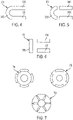
FIG. 4 is a schematic side view of a continuous and unitary U-shaped magnet in accordance with embodiments; -
FIG. 5 is a schematic side view of a non-continuous U-shaped magnet with discrete sections in accordance with embodiments; and -
FIG. 6 is a schematic side view of an angular U-shaped magnet in accordance with embodiments -
FIG. 7 are schematic illustrations of rotor configurations in accordance with embodiments. - As will be described below, an electric motor is provided and has a simplified winding scheme with end windings disposed around back iron to reduce end winding length but still take advantage of distributed winding architecture. That is, the simplified winding scheme is characterized in that it exhibits a high fill factor and provides for higher torque than otherwise available. The electric motor can be provided with a U-shaped rotor configuration with two axial rotors (i.e., a Halbach array) and one semi-axial or radial rotor and takes advantage of torque producing coil sides (3-sides) for producing torque and to allow for effective utilization of the windings.
- With reference to
FIGS. 1A and 1B , anelectric motor 100 is provided and includes arotor 102 configured to rotate about arotation axis 104. Astator 106 is located radially outboard of therotor 102 relative to therotation axis 104, with aradial air gap 108 located between therotor 102 and thestator 106. As illustrated, therotor 102 may be mounted on ashaft 110 which may impart rotational movement to therotor 102 or may be driven by rotation of therotor 102, as will be appreciated by those of skill in the art. Therotor 102 and theshaft 110 may be fixed together such that therotor 102 and theshaft 110 rotate about therotation axis 104 together as one piece. - The
stator 106 includes astator core 112 in which a plurality of electricallyconductive stator windings 114 are disposed. In some embodiments, such as the embodiment shown inFIG. 1A , thestator core 112 is formed from a plurality of axially stackedlaminations 116, which are stacked along therotation axis 104. In some embodiments, thelaminations 116 are formed from a steel material, but one skilled in the art will readily appreciate that other materials may be utilized. Thestator windings 114, as shown, includecore segments 118 extending through thestator core 112 and endturn segments 120 extending from eachaxial stator end 122 of thestator core 112 and connecting circumferentiallyadjacent core segments 118. When thestator windings 114 are energized via an electrical current therethrough, the resulting field drives rotation of therotor 102 about therotation axis 104. - Although
FIG. 1A illustrates thestator core 112 arranged radially inward from thestator windings 114, it will be appreciated that other configurations are possible without departing from the scope of the present disclosure. For example, in some embodiments, the stator structure may be arranged radially inward from a rotating rotor structure. -
FIG. 1B is an axial cross-sectional view of thestator core 112. Eachlamination 116 of thestator core 112 includes a radially outer rim 124 with a plurality of stator teeth 126 extending radially inwardly from the outer rim 124 toward therotation axis 104. Each of the stator teeth 126 terminate at a tooth tip 128, which, together with a rotor outer surface 130 (shown inFIG. 1A ) of therotor 102, may define theradial air gap 108. Circumferentially adjacent stator teeth 126 define an axially-extendingtooth gap 132 therebetween. Further, in some embodiments, a plurality ofstator fins 134 extend radially outwardly from the outer rim 124. - Electric motors, as shown in
FIGS. 1A and 1B may require cooling due to high density configurations, various operational parameters, or for other reasons. For example, high-power-density aviation-class electric motors and drives may require advanced cooling technologies to ensure proper operation of the motors/drives. These machines are generally thermally limited at high power ratings and their performance can be improved by mitigating thermal limitations. To maintain desired temperatures, a thermal management system (TMS) is integrated into the system, which provides cooling to components of the system. Onboard an aircraft, power requirements, and thus thermal management system (TMS) loads, are substantially higher during takeoff. Sizing of the TMS for takeoff conditions (i.e., maximum loads) often results in a TMS having a high weight to accommodate such loads. This can result in greater weight and lower power density during cruise conditions which do not generate such loads, and thus does not require a high cooling capacity TMS. Balancing weight constraints and thermal load capacities is important for such aviation applications. - In view of such considerations, improved aviation electric motors are provided herein. The aviation electric motors or aircraft electric motors, described herein, incorporate lightweight materials and compact design to reduce weight, improve thermal efficiencies, improve power efficiencies, and improve power density.
- Turning now to
FIG. 2 , an aircraftelectric motor 200 is provided and includes amotor housing 202, acondenser 204 and apower module system 206, which is separated from themotor housing 202 by plenum 208. Themotor housing 202 houses astator 210 and arotor 212, with therotor 212 configured to be rotatable about thestator 210. Therotor 212 includes aU-shaped magnet 214 that is arranged within a similarly shapedU-shaped rotor sleeve 216. Therotor sleeve 216 is operably connected to ahub 218, which is fixedly attached to ashaft 220. Theshaft 220 is supported bybearings 222. Thecondenser 204 is configured to provide cooling to the components of the aircraft electric motor 200and can include a heat exchanger and a header forming a closed-loop cooling system that provides air-cooling to a working fluid at the heat exchanger. As the aircraftelectric motor 200 is operated, heat is generated and picked up by the working fluid within embedded cooling channels. The resulting heated working fluid is then passed through the header and back to the heat exchanger to be cooled, such as by air cooling. As shown, thecondenser 204 may be a circular structure arranged about themotor housing 202. This configuration and arrangement allows for improved compactness of the system, which may be advantageous for aircraft applications. Therotor sleeve 216 with themagnets 214, thestator 210 and the gear assembly fit together (although moveable relative to each other) within themotor housing 202, providing for a compact (low volume/size) design. - The
power module system 206 includes capacitors and other electronics, including, but not limited to, printed circuit boards (PCBs) that may enable control and operation of the aircraftelectric motor 200. In general, thepower module system 206 is electrically connected to thestator 210 to cause an electric current therein which will induce an electromagnetic field which will cause therotor 212 to rotate. More particularly, thestator 210 includeswindings 211 to which thepower module 206 is attached and thepower module 206 thus causes the electric current to be applied to thewindings 211. The current in thewindings 211 induces the electromagnetic field to drive therotor 212 rotations. - With continued reference to
FIG. 2 , an integrated motor drive architecture can be provided and includes an electric motor, such as the aircraftelectric motor 200 and thepower module system 206 described above. In these or other cases, thepower module system 206 can be integrated with and can be adjacent to the aircraftelectric motor 200 with plenum 207 (seeFIG. 2 ) axially interposed between thepower module system 206 and the aircraftelectric motor 200. - Referring now to
FIGS. 3A and3B , schematic illustrations of a portion of an aircraftelectric motor 300 in accordance with embodiments is provided for use as theelectric motor 200 ofFIG. 2 . As shown inFIGS. 3A and3B , the portion of the aircraftelectric motor 300 includes arotor 302 and astator 304.FIG. 3A illustrates therotor 302 and thestator 304 andFIG. 3B illustrates these components arranged within arotor sleeve 306. - The
rotor 302 is formed of a plurality of circumferentially arrangedU-shaped magnets 308. In some configurations, the circumferentially arrangedU-shaped magnets 308 can be arranged with alternating polarity arranged in a circular structure. Arranged within the "U" of the circumferentially arrangedU-shaped magnets 308 is thestator 304. Thestator 304 is formed of or supportive of a windingstructure 310. In this configuration, the windingstructure 310 can include or be are arranged with aheader 312. Theheader 312 may be part of a cooling system and can be configured to cycle a working fluid through axially extending coolingchannels 314 for cooling of portions of the windingstructure 310. - As shown in
FIG. 3B , the circumferentially arrangedU-shaped magnets 308 are each U-shaped and arranged within therotor sleeve 306. Therotor sleeve 306 is a substantially U-shaped sleeve that is sized and shaped to receive the circumferentially arrangedU-shaped magnets 308. In this illustrative configuration, therotor sleeve 306 can include aninner sleeve 324. Theinner sleeve 324 may be configured to provide support to a portion of the circumferentially arrangedU-shaped magnets 308. It will be appreciated that there is no direct contact between the windingstructure 310 and the circumferentially arrangedU-shaped magnets 308. This lack of contact enables free rotation of therotor 302 relative to thestator 304 during operation - Each circumferentially arranged
U-shaped magnet 308 includes at least two axial sections and one radial section connection the axial sections. In accordance with embodiments, as shown inFIGS. 3A and3B , each circumferentially arrangedU-shaped magnet 308 includes an inneraxial section 3081, an outeraxial section 3082 and aradial section 3083 and defines an interior 3084 (seeFIG. 3B ) between the inneraxial section 3081, the outeraxial section 3082 and theradial section 3083. - The winding
structure 310 can be electrically connected to one or more power module systems and includesfirst phase coils 3101,second phase coils 3102 andend windings 3103. Thefirst phase coils 3101 extend axially within the interior 3084 for torque production with the inner and outeraxial sections U-shaped magnet 308. Thesecond phase coils 3102 respectively extend radially within the interior 3084 between corresponding interior ends of sequential pairs of thefirst phase coils 3101 for torque production with theradial section 3083 of each circumferentially arrangedU-shaped magnet 308. Theend windings 3103 respectively extend outside the interior 3084 between corresponding exterior ends of sequential pairs of the first phase coils 3101. - In accordance with embodiments, the first and
second phase coils - In accordance with embodiments, the winding
structure 310 generates a decoupled flux pattern between respective flux patterns of the inner and outeraxial sections U-shaped magnet 308 when current is applied to the first andsecond phase coils end windings 3103. Also, the inneraxial sections 3081 of the circumferentially arrangedU-shaped magnets 308 can be arranged in a Halbach array formation and the outeraxial sections 3082 of the circumferentially arrangedU-shaped magnets 308 can be arranged in a Halbach array formation. - At least the first and second phase coils 301 and 302 of the winding
structure 310 can be wrapped about asupport structure 316. Thesupport structure 316 may include a laminate axially extendingmember 318 and a soft magnetic composite (SMC)tip 320. The laminate axially extendingmember 318 may be formed from cobalt steel laminate. In accordance with embodiments, the laminate axially extendingmember 318 can be formed of laminates, SMC or some combinations thereof. Similarly, in accordance with additional or alternative embodiments, theSMC tip 320 can be formed of SMC, laminates or some combinations thereof. In any case, it is to be understood that the presence of theSMC tip 320 serves to generate torque at or proximate to the location at which theU-shaped magnets 308 turn. - With reference to
FIGS. 4-6 and in accordance with embodiments, particular configurations of each circumferentially arrangedU-shaped magnet 308 will now be described. As shown inFIG. 4 (and inFIGS. 3A and3B ), the inneraxial section 3081, the outeraxial section 3082 and theradial section 3083 of each circumferentially arrangedU-shaped magnet 308 cooperatively form a continuous andunitary magnet 401. Alternatively, as shown inFIG. 5 , the inneraxial section 3081, the outeraxial section 3082 and theradial section 3083 of each circumferentially arrangedU-shaped magnet 308 are non-continuous and discrete from one another. In other alternative embodiments, the inneraxial section 3081, the outeraxial section 3082 and theradial section 3083 of each circumferentially arrangedU-shaped magnet 308 form an angular U-shape 601 (as opposed to the rounded U-shapes ofFIGS. 4 and 5 ). In any case, as indicated by the dashed arc-arrows ofFIG. 3B , the inneraxial section 3081 and the outeraxial section 3082 can be circumferentially shifted with respect to one another. Similarly, as is also indicated by the dashed arc-arrows ofFIG. 3B , the first andsecond phase coils - With reference to
FIG. 7 and in accordance with embodiments, the circumferentially arrangedU-shaped magnets 308 ofFIGS. 3A ,3B ,4, 5 and 6 can each have at least one or more of a surface permanent magnet (SPM)formation 701, an internal permanent magnet (IPM)formation 702 and aspoke formation 703 as well as other variants. In accordance with embodiments, the formation of the inneraxial section 3081 and the outeraxial section 3082 can be the same or different from one another. - Technical effects and benefits of the present disclosure are the provision an electric motor with a dual rotor configuration (i.e., a Halbach array) which can take advantage of torque producing coils for producing torque and to allow for effective utilization of the windings. This allows the electric motor to operate at increased torque density with reduced end winding size, weight and losses and with a simplified construction and an improved production rate.
- The corresponding structures, materials, acts, and equivalents of all means or step plus function elements in the claims below are intended to include any structure, material, or act for performing the function in combination with other claimed elements as specifically claimed. The description of the present disclosure has been presented for purposes of illustration and description, but is not intended to be exhaustive or limited to the technical concepts in the form disclosed. Many modifications and variations will be apparent to those of ordinary skill in the art without departing from the scope of the invention as defined by the claims. The embodiments were chosen and described in order to best explain the principles of the disclosure and the practical application, and to enable others of ordinary skill in the art to understand the disclosure for various embodiments with various modifications as are suited to the particular use contemplated.
- While the preferred embodiments to the disclosure have been described, it will be understood that those skilled in the art, both now and in the future, may make various improvements and enhancements which fall within the scope of the claims which follow. These claims should be construed to maintain the proper protection for the disclosure first described.
Claims (15)
- An electric motor, comprising:a U-shaped rotor (302) comprising circumferentially arranged U-shaped magnets (308), each circumferentially arranged U-shaped magnet defining an interior; anda stator (304) supportive of a winding structure (310) comprising:phase coils (3101, 3102) extending axially and radially within the interior for torque production with each circumferentially arranged U-shaped magnet; andend windings (3103) respectively extending outside the interior between corresponding ends of sequential pairs of the phase coils.
- The electric motor according to claim 1, wherein the winding structure (310) generates a decoupled flux pattern when current is applied to the phase coils and the end windings.
- The electric motor according to claim 1 or 2, wherein each circumferentially arranged U-shaped magnet (308) is continuous and unitary or has non-continuous and discrete sections.
- The electric motor according to claim 1, 2 or 3, wherein each circumferentially arranged U-shaped magnet has a rounded U-shape or an angular U-shape.
- The electric motor according to any preceding claim, wherein:the stator (304) is formed to define axially extending cooling channels, andthe stator comprises an axially extending member (318) with a soft magnetic composite (SMC) tip (320) disposed in the interior.
- The electric motor according to any preceding claim, wherein the phase coils are each provided with three phases, an odd number of phases greater than three or a multiple of three phases.
- The electric motor of claim 1 or 2, the phase coils comprising:first phase coils (3101) extending axially within the interior for torque production with the two axial sections of each circumferentially arranged U-shaped magnet;second phase coils (3102) extending radially within the interior for torque production with the one radial section of each circumferentially arranged U-shaped magnet; andthe end windings respectively extending outside the interior between corresponding exterior ends of sequential pairs of the first phase coils.
- The electric motor according to claim 7, wherein the two axial sections (3081, 3082) of the circumferentially arranged U-shaped magnets are arranged in a Halbach array, or wherein the two axial sections and the radial section (3083) of each circumferentially arranged U-shaped magnet cooperatively form a continuous and unitary magnet or are non-continuous and discrete from one another, or wherein the two axial sections and the radial section of each circumferentially arranged U-shaped magnet form a rounded U-shape or an angular U-shape.
- The electric motor according to claim 7 or 8, wherein:the stator is formed to define axially extending cooling channels, andthe stator comprises an axially extending member (318) with a soft magnetic composite (SMC) tip (320) disposed in the interior.
- The electric motor according to claim 7, 8 or 9, wherein the first and second phase coils are each provided with three phases, an odd number of phases greater than three or a multiple of three phases.
- An electric motor as claimed in claim 1 or 2, comprising:
each circumferentially arranged U-shaped magnet comprising an inner axial section, an outer axial section and a radial section and defining the interior between the inner axial section, the outer axial section and the radial section; and the coils comprisingfirst phase coils (3101) extending axially within the interior for torque production with the inner and outer axial sections of each circumferentially arranged U-shaped magnet;second phase coils (3102) respectively extending radially within the interior between corresponding interior ends of sequential pairs of the first phase coils for torque production with the radial section of each circumferentially arranged U-shaped magnet; andthe end windings (3103) respectively extending outside the interior between corresponding exterior ends of sequential pairs of the first phase coils. - The electric motor according to claim 11, wherein the winding structure generates a decoupled flux pattern between respective flux patterns of the inner and outer axial sections of each circumferentially arranged U-shaped magnet when current is applied to the first and second phase coils and the end windings.
- The electric motor according to claim 11 or 12, wherein:the inner axial sections (3081) of the circumferentially arranged U-shaped magnets are arranged in a Halbach array, andthe outer axial sections (3082) of the circumferentially arranged U-shaped magnets are arranged in a Halbach array, or wherein at least one of:
the inner axial section and the outer axial section of each circumferentially arranged U-shaped magnet are circumferentially shifted, andthe first phase coils are circumferentially shifted with respect to the second phase coils.; or wherein:the inner axial section, the outer axial section and the radial section of each circumferentially arranged U-shaped magnet cooperatively form a continuous and unitary magnet or are non-continuous and discrete from one another, andthe inner axial section, the outer axial section and the radial section of each circumferentially arranged U-shaped magnet form a rounded U-shape or an angular U-shape. - The electric motor according to claim 11, 12 or 13, wherein:the stator is formed to define axially extending cooling channels, andthe stator comprises an axially extending member (318) with a soft magnetic composite (SMC) tip (320) disposed in the interior.
- The electric motor according to any of claims 11 to 14, wherein the first and second phase coils are each provided with three phases, an odd number of phases greater than three or a multiple of three phases.
Applications Claiming Priority (1)
| Application Number | Priority Date | Filing Date | Title |
|---|---|---|---|
| US17/223,307 US11973376B2 (en) | 2021-04-06 | 2021-04-06 | Electric motor with simplified winding and U-shaped rotor |
Publications (1)
| Publication Number | Publication Date |
|---|---|
| EP4089884A1 true EP4089884A1 (en) | 2022-11-16 |
Family
ID=81325321
Family Applications (1)
| Application Number | Title | Priority Date | Filing Date |
|---|---|---|---|
| EP22166822.1A Pending EP4089884A1 (en) | 2021-04-06 | 2022-04-05 | Electric motor with simplified winding and u-shaped rotor |
Country Status (2)
| Country | Link |
|---|---|
| US (1) | US11973376B2 (en) |
| EP (1) | EP4089884A1 (en) |
Cited By (1)
| Publication number | Priority date | Publication date | Assignee | Title |
|---|---|---|---|---|
| EP4372967A1 (en) * | 2022-11-17 | 2024-05-22 | Hamilton Sundstrand Corporation | Electric machine having notched magnets |
Citations (6)
| Publication number | Priority date | Publication date | Assignee | Title |
|---|---|---|---|---|
| FR2653274A1 (en) * | 1989-10-16 | 1991-04-19 | Auxilec | IMPROVEMENT OF THE ELECTRIC MOTOR OF THE BRUSHLESS DIRECT CURRENT MOTOR TYPE. |
| US20090102305A1 (en) * | 2005-06-29 | 2009-04-23 | Union Plastic (Hangzhou) Machinery Co., Ltd. | Brushless electric machine |
| JP4728639B2 (en) * | 2004-12-27 | 2011-07-20 | 株式会社デンソー | Electric wheel |
| CN106233579A (en) * | 2013-01-24 | 2016-12-14 | 清水控股有限公司 | Flux electric machine |
| US20180219464A1 (en) * | 2014-07-23 | 2018-08-02 | Clearwater Holdings, Ltd. | Flux machine |
| WO2019235953A1 (en) * | 2018-06-04 | 2019-12-12 | Shcherbakov Vadim Valerevich | Electric machine |
Family Cites Families (10)
| Publication number | Priority date | Publication date | Assignee | Title |
|---|---|---|---|---|
| US4731554A (en) | 1985-11-14 | 1988-03-15 | Allied Corporation | Low profile ring-shaped motor |
| US20120212085A1 (en) * | 2011-02-17 | 2012-08-23 | The Hong Kong Polytechnic University | Axial-flux electric machine |
| JP5869592B2 (en) * | 2011-02-28 | 2016-02-24 | ユーキューエム テクノロジーズ インコーポレーテッド | Brushless permanent magnet electric machine capable of using low coercivity magnets |
| KR102150817B1 (en) * | 2012-03-20 | 2020-10-16 | 리니어 랩스, 엘엘씨 | An improved dc electric motor/generator with enhanced permanent magnet flux densities |
| US20150137647A1 (en) * | 2012-03-20 | 2015-05-21 | Linear Labs, Inc. | Brushless electric motor/generator |
| US20140183988A1 (en) * | 2012-12-31 | 2014-07-03 | Teco-Westinghouse Motor Company | Assemblies For Cooling Electric Machines |
| US10491069B2 (en) * | 2014-09-16 | 2019-11-26 | Greentech Motors Corporation | Electric motor with laminated sheet windings |
| CN105576865B (en) * | 2014-10-30 | 2020-03-06 | 株式会社捷太格特 | Magnet-embedded rotor, method and apparatus for manufacturing the same |
| GB2534196B (en) | 2015-01-16 | 2017-06-14 | Yasa Motors Ltd | Axial flux machine |
| US11923733B2 (en) * | 2020-08-28 | 2024-03-05 | Quantentech Limited | High efficiency high density motor and generator with multiple airgaps |
-
2021
- 2021-04-06 US US17/223,307 patent/US11973376B2/en active Active
-
2022
- 2022-04-05 EP EP22166822.1A patent/EP4089884A1/en active Pending
Patent Citations (6)
| Publication number | Priority date | Publication date | Assignee | Title |
|---|---|---|---|---|
| FR2653274A1 (en) * | 1989-10-16 | 1991-04-19 | Auxilec | IMPROVEMENT OF THE ELECTRIC MOTOR OF THE BRUSHLESS DIRECT CURRENT MOTOR TYPE. |
| JP4728639B2 (en) * | 2004-12-27 | 2011-07-20 | 株式会社デンソー | Electric wheel |
| US20090102305A1 (en) * | 2005-06-29 | 2009-04-23 | Union Plastic (Hangzhou) Machinery Co., Ltd. | Brushless electric machine |
| CN106233579A (en) * | 2013-01-24 | 2016-12-14 | 清水控股有限公司 | Flux electric machine |
| US20180219464A1 (en) * | 2014-07-23 | 2018-08-02 | Clearwater Holdings, Ltd. | Flux machine |
| WO2019235953A1 (en) * | 2018-06-04 | 2019-12-12 | Shcherbakov Vadim Valerevich | Electric machine |
Cited By (1)
| Publication number | Priority date | Publication date | Assignee | Title |
|---|---|---|---|---|
| EP4372967A1 (en) * | 2022-11-17 | 2024-05-22 | Hamilton Sundstrand Corporation | Electric machine having notched magnets |
Also Published As
| Publication number | Publication date |
|---|---|
| US11973376B2 (en) | 2024-04-30 |
| US20220320928A1 (en) | 2022-10-06 |
Similar Documents
| Publication | Publication Date | Title |
|---|---|---|
| EP4071983B1 (en) | Aircraft electric motor | |
| EP4087091A1 (en) | Aircraft electric motor | |
| GB2436019A (en) | Rotor cooling system for synchronous machines with conductive sleeves | |
| CN112583146A (en) | Transverse flux machine | |
| EP4262053A1 (en) | Aircraft electric motor | |
| EP1488495A1 (en) | Electric motor integrated in a vehicle wheel | |
| EP4071974B1 (en) | Aircraft electric motor | |
| EP4184758A1 (en) | Aircraft electric motor | |
| US20250300540A1 (en) | Torque dense electric motor | |
| US11973376B2 (en) | Electric motor with simplified winding and U-shaped rotor | |
| EP4030591A2 (en) | Rotor assembly of an electric machine comprising a sheath | |
| US11728715B2 (en) | Electric motor with simplified winding and dual rotor | |
| US12348084B2 (en) | Electric machine having multi-function cooling channels | |
| US20240195233A1 (en) | Magnetic wire infused components for electric machine | |
| EP4372967A1 (en) | Electric machine having notched magnets | |
| EP4412044A1 (en) | Electric machine having rotor with integrated fan | |
| EP4071985A1 (en) | Integrated motor drive architecture | |
| US12294246B2 (en) | Aircraft electric motor | |
| US20260081504A1 (en) | Electric machine having notched magnets and integrated cooling | |
| CN120834663A (en) | Permanent magnet motor and method for field weakening in a permanent magnet motor | |
| EP3496233A1 (en) | Electric generator having end-windings with reduced axial protrusion |
Legal Events
| Date | Code | Title | Description |
|---|---|---|---|
| PUAI | Public reference made under article 153(3) epc to a published international application that has entered the european phase |
Free format text: ORIGINAL CODE: 0009012 |
|
| STAA | Information on the status of an ep patent application or granted ep patent |
Free format text: STATUS: THE APPLICATION HAS BEEN PUBLISHED |
|
| AK | Designated contracting states |
Kind code of ref document: A1 Designated state(s): AL AT BE BG CH CY CZ DE DK EE ES FI FR GB GR HR HU IE IS IT LI LT LU LV MC MK MT NL NO PL PT RO RS SE SI SK SM TR |
|
| STAA | Information on the status of an ep patent application or granted ep patent |
Free format text: STATUS: REQUEST FOR EXAMINATION WAS MADE |
|
| 17P | Request for examination filed |
Effective date: 20230516 |
|
| RBV | Designated contracting states (corrected) |
Designated state(s): AL AT BE BG CH CY CZ DE DK EE ES FI FR GB GR HR HU IE IS IT LI LT LU LV MC MK MT NL NO PL PT RO RS SE SI SK SM TR |
|
| STAA | Information on the status of an ep patent application or granted ep patent |
Free format text: STATUS: EXAMINATION IS IN PROGRESS |
|
| 17Q | First examination report despatched |
Effective date: 20260116 |